Embed Size (px)
Citation preview

Guide ModelSim
ModelSim SE6.3j, PE (Mentor Graphics)
Designflow
1/14 Version: 11/2012 Pal

Content 1 Konfiguration 3................2
1 Configuration 3
1.1 Create a Project 3
1.2 Add Files to the Project 4
2 Functional Simulation 5
2.1 Compilation 5
2.2 Errorcorrection of Compilation 6
2.3 Start of Simulation 7
2.4 Stimulation without DO- File 8 2.5 Stimulation, Run of a DO- File 9
2.6 Handling of the Wave-window 10
3 Timing Simulation, Start of Simulation 11
3.1 Start of Simulation with DO-File 11
3.2 Timing Simulation with a Testbench 13
3.3 Testbench for Timing Simulation 14
2/14

Start of from Desktop :
1. Konfiguration
1. 1 Create a Project
A new project (projectfolder, projectfile ~.mpf) will be created with:
→ File → New → Project
The menue „Create Project“ appears:
The only entry to do is the name of the project.
Note that
no special signs (except underscore),
no space,
no german „ Umlaute“ or
not more than 20 signs
should be used.
In the lines „Project Location“, „Default Library Name“, and
„Copy Settings From“ take care that the default settings are the same as above.
Normally there are no changes necessary. (Exception: On your private PC.)
Go on with click on
The selection menue „Add Items to the Project „ follows automatically:
3/14
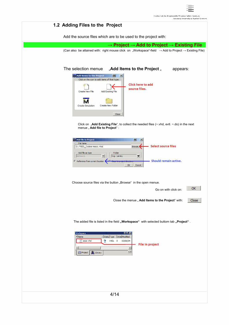
1.2 Adding Files to the Project
Add the source files which are to be used to the project with:
→ Project → Add to Project → Existing File(Can also be attained with: right mouse click on „Workspace“-field → Add to Project → Existing File)
The selection menue „Add Items to the Project „ appears:
Click on „Add Existing File“, to collect the needed files (~.vhd, evtl. ~.do) in the next menue „ Add file to Project“ :
Choose source files via the button „Browse“ in the open menue.
Go on with click on:
Close the menue „ Add Items to the Project“ with:
The added file is listed in the field „Workspace“ with selected buttom tab „Project“ .
4/14

2. Funktional Simulation 2.1 Compilation
At first the VHD-sourcodes must be compiled successfully. Mark the according sourcefile in „Workspace“ execute:
→ Compile → Compile Selected
Or right mouseclick on the file and → Compile Selected
Or → Compile All
With components take care of the compile order. (Subcomponent first)
In the Transcript-window the success message appears when there are no errors:
# Compile of >Dateiname< was successful.
The status of the file receives a green hook.
With this you can go on with chapter:
Start of Simulation.
A compile error is signalled by a red cross in the status column:
. And by an error message in the transcript window.
In this case you have to go to chapter;
Errorcorrection in Compilation
2.2 Errorcorrection in Compilation
5/14

Errorcorrection in Compilation
Double left mouseclick on filename in „Workspace“ opens it in editor.
Double left mouseclick on the error line in „Transcript“-window opens awindow with a detailederror description.
The Filename with the hole path and the linenumber in round brackets can be seen (here 3),followed by a hint.
Double left mouse click on this „error“-line marks this line of the sourcecode in the editor:
Recommended procedure:
Improve the error on top of the list (The following errors are mostly sequential errors.) , save the sourcefile, and compile again.
It can happen that after the correction of an error after the new compilation more errors are reported thanbefore. The cause for this can be that in the first case the architecture was not compiled because of a severe error in the port list. .Sometimes the eror can be found a line above the error line. e.g. a lost semicolon Auch Warnungen sind zu korrigieren.
This procedure has oftenly done several times until at last the compiler reports no errors.Improve also the warnings mostly a space between number and a timeunit in order that other warning are not passed over.
. The status of the file gets a green hook:
Now go on to the topic : Start of Simulation.
6/14

2.3 Start of Simulation The simulation can only be started after a successful compilation with:
→ Simulation → Start Simulation
The menue „Start Simulation“ opens:
Here choose in → Design → work E = Entity or A = Architektur .
The default resolution (of time ) is according to ini-file : ps (pico seconds)
This is needed for the timing simulation.
For the functional simulation it will be sufficient: ns (nano seconds)
Go on with:
Now new window will came into existance: Objects, Active Processes
and additional subpositioned windows in region „Workspace“ : Sim, Files, Memories
7/14

2.4 Stimulation without Do-File
Stimulation without DO-File
After → Simulate → Start Simulation and choice of „Entity“ or „Architecture“
input and output signals become visible in window „Objects“ .
With right mouse click on a signal choose
→ Add to Wave → Signals in Region
The „Wave“-window appears for the time display with the wanted signals.
Stimulation of a signal: With right mouse click on a signal choose:
→ Force
In menue „Force Selected Signal“ in line „Value“ write 0 or 1 level.
( Only for input signals bit as 0 or 1, vektors in hex: e.g. 1E3 )
Now fill in a simulation time in the small field „Run Length“ in the button row. e.g. 100 ns
With right mouse click on the button „Run“ right next simulation will be done:
8/14

2.5 Stimulation with a DO-File
→ Tools → TCL → Execute Makro
A first instruction „restart“ in a DO-file will
produce a little menue.:
Here one can keep several settings.
If one starts for the first time there is nothing to keep.
But for the following runs one normally doesn't keep „Wave Format“ in order to display onlyone simulation.
Deaktivate → Keep → Wave Format
Go on with „Restart“ .
DO-File faster start:
Right mouse click in „Workspace“ and select → Add to Project → Existing File .
In menü „ Add File to Project“ click „Browse“ and import a DO-file.
Here set the extensionfilter right at the buttom to „All Files (*.*)“ .
So the DO-file appears aditionally in „Workspace“ and can easyly be started with
right mous eclick on the entree of the DO-file and select → Execute .
3 Examples of a stimulation in a DO- file :
Following instructions atre neede: „restart“, „add wave2 and „force“.
Select a numberformat : radix hex { bin, dec, oct }
„Force“ is the setting of a value and works as follows:
force >signal name< >Value< [ >time< , >Value< >time< , >Value< >time< ]
In „Repeat“-Mode „-r“ especially for the clock :
force >signal name< >Value< >time< , >Value< >time< -r >periodic time<
9/14

2.6 Handling of the Wave-Window
The Wave-Window
The wave windows opens with the smallest resolution and often shows only the very ending.
With click on „Full Zoom“ the whole simulation will be shown from the beginning.
Zoomfunctions:
1. Zoom In : Magnify
2. Zoom Out : Reduction
3. Zoom Full : Whole
4. Zoom In on active Cursor : Magnify at cursor position
In the first row the signal names are listed, in the second the value at cursorposition.
More cursors will be created by click on the small green button :
at the buttom left side of the timescale.
The background of the wave-window can be changed by two prepared TCL-files:
With → Tools → TCL → Execute Makro
In the folder D:/ISE_Lab_Files/ModelSim_Makros the file WaveBackgroundBlack.tcl for a black
or WaveBackgroundwhite.tcl for a white background.
Magnify the wave window with:: 1. Enlarge to the full screen width
2. Unfix the wave window
With the „Buttons“ „ Find Previous Transition“ and „Find Next Transition“ the cursors can be exactly positioned on an edge of a signal:
10/14

3.1 Timing Simulation, Start of the Simulation with a DO-File Timing Simulation
→ Simulation → Start Simulation
Two files which are needed will be created by the implementation tool ISE in using the function: → Implementation → Optional Implementation Tools --> „Generate Post-Fit Simulation Model“ They will be in folder <projektname>/netgen/fit for CPLDs or <projektname>/netgen/par for FPGAs:
<Entity_name>_timesim.vhd and <Entity_name>_timesim.sdf (Standard Delay Format)
Add the file ~_timesim.vhd to the project with right mouse click on workspace and choose:
→ Add to Project → Existing File and button „Browse“
Compile this file with : → Compile → Compile Selected Then go on with → Simulate → Start Simulation .
But here at first add the SDF-file to the project as follows:
Click the „SDF“-Tab and then the button „Add“ . Browse to the SDF-file in the ISE-projectfolder:
A former done selection can be altered by the buttons Modify or Delete . When a testbench is used the instance name has to be filled in in the field „Apply to region“. (See also 3.2)
Go on with „Design“-Tab :
11/14
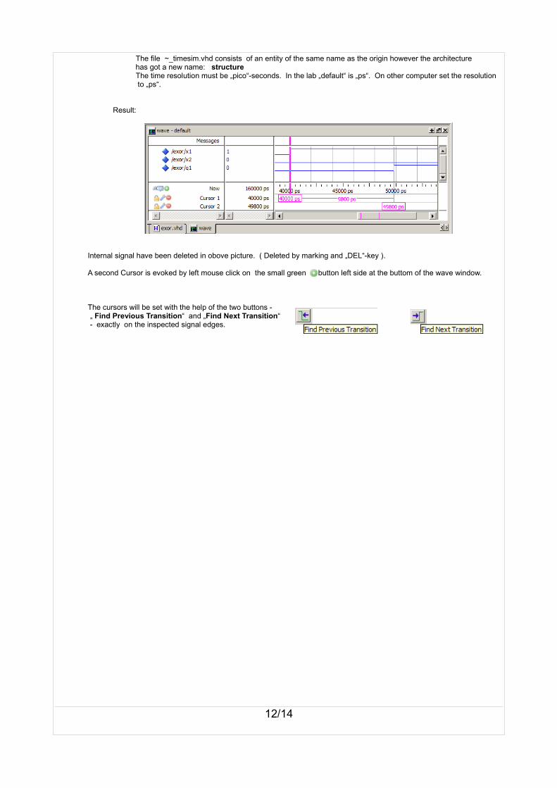
The file ~_timesim.vhd consists of an entity of the same name as the origin however the architecture has got a new name: structure
The time resolution must be „pico“-seconds. In the lab „default“ is „ps“. On other computer set the resolution to „ps“.
Result:
Internal signal have been deleted in obove picture. ( Deleted by marking and „DEL“-key ).
A second Cursor is evoked by left mouse click on the small green button left side at the buttom of the wave window.
The cursors will be set with the help of the two buttons - „ Find Previous Transition“ and „Find Next Transition“ - exactly on the inspected signal edges.
12/14

3.2 Timing Simulation with a Testbench Timing simulation
→ Simulation → Start Simulation
Two files which are needed will be created by the implementation tool ISE in using the function: → Implementation → Optional Implementation Tools --> „Generate Post-Fit Simulation Model“
They will be in folder <projektname>/netgen/fit for CPLDs or <projektname>/netgen/par for FPGAs:
<Entity_name>_timesim.vhd and <Entity_name>_timesim.sdf (Standard Delay Format)
Add the file ~_timesim.vhd to the project with right mouse click on workspace and choose:
→ Add to Project → Existing File and button „Browse“
Compile this file with : → Compile → Compile Selected Then go on with → Simulate → Start Simulation .
But here at first add the SDF-file to the project as follows:
Click the „SDF“-Tab and then the button „Add“ . Browse to the SDF-file in the ISE-projectfolder:
In the edit field „Apply to Region“ the instance name must be filled in (incl. „/“ „Slash“), so the time dates delivered by the SDF-file are attached to the proper instance .
Oftenly e.g.. DUT (Device under Test) or UUT ( Unit under Test)
In the testbench the component of the topentity design is instanciated with an instance name and thefollowing „port map“ shows the connections of the signals.
With Delete or Modify the entry can be changed.
Go on with the tab: „Design“.
Here the Entity of the Testbench has to be chosen and go on with :
The time resolution must be „pico“-seconds. In the lab „default“ is „ps“. On other computer set the resolution to „ps“.
13/14

A minimal DO-file or by several mouseclicks the result shows up:
A second Cursor is evoked by left mouse click on the small green button left side at the buttom of the wave window. The cursors will be set with the help of the two buttons - „ Find Previous Transition“ and „Find Next Transition“ - exactly on the inspected signal edges.
3.3 Testbench for the Timing Simulation Testbench
The testbench must be changed in order to fit to the ~timesim.vhd-design of ISE.
ISE uses only „std_logic“ und „std_logic_vector“ . So there are following supplements and changes to do:
1. Additional Libs: library IEEE;
use IEEE.STD_LOGIC_1164.ALL;
2. All „ bit“ and all „bit_vector“ hav e to be altered to „ std_logic“ and „std_logic_vector“ e.g. with the help of → Edit → Replace
The sequenz of the signals is mostly not kept in the _timesim.vhd“-file. So use the connection sign for the signals in the port map:
3. Change the „port map“ :z.B.port map ( X1 => X1_TB,
X2 => X2_TB, Q1 => Q1_TB );
„Generics“ are not supported.
4. Replace „Generics“ by the fixed vector lenght.
The use of a minimal DO-file is convenient :
restartview signalsview wave
add wave EXOR_TB/*
run 200 ns
14/14