Embed Size (px)
Citation preview

applied sciences
Review
Green Gas for Grid as an Eco-Friendly AlternativeInsulation Gas to SF6: A Review
Baofeng Pan 1, Guoming Wang 2,* , Huimin Shi 1, Jiahua Shen 2, Hong-Keun Ji 3 andGyung-Suk Kil 4,*
1 School of Port and Transportation Engineering, Zhejiang Ocean University, Zhoushan 316022, China;[email protected] (B.P.); [email protected] (H.S.)
2 Hangzhou Guozhou Power Technology Co., Ltd., Hangzhou 310015, China; [email protected] Forensic Safety Section, National Forensic Service Busan Institute, Yangsan 50612, Korea; [email protected] Department of Electrical and Electronics Engineering, Korea Maritime and Ocean University,
Busan 49112, Korea* Correspondence: [email protected] (G.M.); [email protected] (G.-S.K.);
Tel.: +82-51-410-4414 (G.-S.K.)
Received: 3 March 2020; Accepted: 3 April 2020; Published: 7 April 2020�����������������
Featured Application: Insulation design of gas-insulated electrical power facilities usingeco-friendly green gas for a grid (g3) to replace SF6 that causes environmental concerns.
Abstract: This paper deals with a review of the state-of-the-art performance investigations ofgreen gas for grid (g3) gas, which is an emerging eco-friendly alternative insulation gas for sulfurhexafluoride (SF6) that will be used in gas-insulated power facilities for reducing environmentalconcerns. The required physical and chemical properties of insulation gas for high-voltage applicationsare discussed, including dielectric strength, arc-quenching capability, heat dissipation, boiling point,vapor pressure, compatibility, and environmental and safety requirements. Current studies andresults on AC, DC, and lightning impulse breakdown voltage, as well as the partial discharge of g3gas, are provided, which indicate an equivalent dielectric strength of g3 gas with SF6 after a properdesign change or an increase in gas pressure. The switching bus-transfer current test, temperaturerise test, and liquefaction temperature calculation also verify the possibility of replacing SF6 with g3gas. In addition, the use of g3 gas significantly reduces theabovementioned environmental concernsin terms of global warming potential and atmosphere lifetime. In recent years, g3 gas-insulatedpower facilities, including switchgear, transmission line, circuit breaker, and transformer, have beencommercially available in the electric power industry.
Keywords: green gas for grid (g3); eco-friendly insulation gas; SF6 alternative; gas-insulated powerfacilities; dielectric strength; global warming potential (GWP)
1. Introduction
Sulfur hexafluoride (SF6) has been used as the most popular insulation gas in gas-insulated powerfacilities, such as switchgear (GIS), circuit breaker (GCB), transmission line (GIL), and transformer(GIT), since 1947. This is because SF6 has an exceptional combination of physical and chemicalproperties for high-voltage applications, including high-dielectric strength (three times that ofair at atmospheric pressure), arc-quenching capability, thermal conductivity, thermal stability,nonflammability, nontoxicity, nonexplosive, and chemical inertness [1–4]. As a result, SF6-insulatedequipment can be designed with reduced size, high reliability, and economic efficiency [5,6]. It iswidely employed in space-limited locations such as city substations, offshore plants, or wind-powerplants [7].
Appl. Sci. 2020, 10, 2526; doi:10.3390/app10072526 www.mdpi.com/journal/applsci

Appl. Sci. 2020, 10, 2526 2 of 13
However, SF6 was labeled as one of the greenhouse gases in the Kyoto Protocol and ParisAgreements owing to its excessive size, radiative effect, and atmospheric lifetime [8–12]. The globalwarming potential (GWP) of SF6 is 23,500 times that of carbon dioxide (CO2) over a 100-year timehorizon and is 32,600 times that of CO2 over a 500-year time horizon. The atmospheric lifetime of SF6
is 3200 years, whereas that of CO2 is only 30–90 years [1]. It was reported that 1 kg of SF6 releasedinto the atmosphere has the equivalent global warming impact as 23.5 tons of CO2 [13]. Therefore,emission and consumption of SF6 must be controlled by the year 2020 and regulations have beenimplemented to reduce the environmental impact caused by SF6 [14–16]. In addition, SF6 decomposesinto lower fluorides of sulfur when an electrical discharge such as an arc, spark, or corona occurs.Some decomposition byproducts, including disulfur decafluoride (S2F10), sulfur tetrafluoride (SF4),and hydrogen fluoride (HF), are known to be highly reactive, corrosive, and toxic, which cause greatconcerns regarding equipment lifetime and personnel safety [17,18].
Negative impacts have led the power industry to seek an eco-friendly alternative insulationgas to partially or completely replace SF6. Studies have been carried out to investigate thepotential of natural gases such as CO2 [19] and nitrogen (N2) [20], and dry air, vacuum, SF6
gas mixture [20–22], and fluorinated gases with reduced GWP such as trifluoroiodomethane(CF3I) [4,13,14,23,24], perfluorocarbons (PFCs) [1,25], as well as hydrofluoroolefins (HFOs) [7,26].Unfortunately, all of them have respective drawbacks, making them unsuitable for application inhigh-voltage gas-insulated equipment.
Recently, green gas for grid (g3), which was developed in collaboration by General Electric and3M Company, has been regarded as the latest generation insulation gas and is the most promisingcandidate for replacing SF6. G3 is a gas mixture that is composed of C4F7N (NovecTM 4710) andCO2 or N2, which aims to reduce the environmental impact and to find a compromise between thedielectric performance and the minimum operating temperature of the apparatus [26–28]. Properties ofg3 gas have been individually studied in the past five years, whereas a comprehensive overview ofg3 gas for applications in high-voltage gas-insulated equipment has not been presented until now.This paper firstly discusses the required physical and chemical properties of gas for high-voltageinsulation applications and then carries out a review on the state-of-the-art performance investigationsof g3 gas.
2. Required Physical and Chemical Properties of Insulation Gas
An environmentally sustainable insulation gas alternative to SF6 should be compliant withthe stringent requirements of high-voltage applications [29,30]. The physical and chemicalproperties include
• High-dielectric strength;• Good arc-quenching capability;• High heat dissipation (high thermal conductivity);• Low boiling point and high vapor pressure at low temperature;• Compatibility with other materials; and• Design compactness.
In addition, it also has to meet environmental and safety requirements, such as
• Low GWP;• No ozone depletion potential (ODP);• Low toxicity; and• Nonflammable and nonexplosive.
Appl. Sci. 2020, 10, 2526 3 of 13
2.1. Dielectric Strength
The dielectric strength is investigated by AC, DC, and lightning impulse breakdown voltage,which is performed in the electrode arrangement and practical gas-insulated power facilities.Breakdown mechanisms of insulation gases can be theoretically explained by Paschen’s law and theTownsend theory [31,32]. The AC and DC breakdown voltages are tested by raising the applied voltageat a constant rate until the breakdown occurs. The lightning impulse breakdown voltage, which isrepresented by 50% breakdown strength, is determined by the up-and-down method by applying a1.2/50 s standard lightning pulse voltage. Since it is used for determining the basic insulation level of asystem, the lightning impulse test is a crucial test. The breakdown test, under the same condition, isrepeated multiple times so that the mean value and standard deviation of the breakdown voltage arecalculated by evaluating the gas performance [28,33]. Various conditions should be taken into accountfor determining the breakdown voltage, including the homogenous and inhomogeneous field, surfaceroughness, insulation defects, free-moving conductive particles, and contamination [34–37].
In addition to the breakdown voltage, partial discharge (PD) is the other criterion for evaluatingthe dielectric strength. According to the International Electrotechnical Commission (IEC) 60270, PD isa localized electrical discharge that only partially bridges the insulation between conductors, and itcan or cannot occur adjacent to a conductor [38]. It occurs at any point in the insulation system wherethe electric field strength exceeds the breakdown strength of gas. Therefore, PD is regarded as an earlystage of breakdown [39–41]. PD characteristics, in terms of partial discharge inception voltage (PDIV),discharge magnitude, and pulse count as a function of gas pressure and insulation distance, are usedto compare the insulation performance of alternative gases [42–44].
2.2. Arc-Quenching Capability
Insulation gases should have the ability to interrupt a large current during the switching operationof the circuit breaker [45,46]. Important gas properties for arc interruption are required. The insulationgas should be electronegative to capture the freed electron fast and to reduce its moving speed [47].As arc temperature is more than 10,000 K; gases should have high thermal conductivity to quicklycool down the temperature. In addition, molecules may be dissociated at a high temperature.The fast dielectric recovery is, therefore, required to recombine gas to form its original structure [36].The arc-interrupting ability is evaluated by the thermal-interrupting test and the dielectric-recoverytest. The arc conductivity, at hundreds of nanoseconds before current zero, is used as a performanceindicator of the thermal-interrupting test [48,49]. The dielectric recovery test is currently done by acomputational fluid dynamic of gas flow [50].
2.3. High Heat Dissipation (High Thermal Conductivity)
High heat dissipation capability is not only required to ensure arc-quenching ability but is alsoessential to transmit heat from the conductor and contact that is caused by the large current [51,52]. It isspecified in the IEC 62271 that the highest temperature of the busbar and enclosure must not exceed105 ◦C and 70 ◦C, respectively. The maximum allowable temperature rise during the steady-stateoperation of the busbar must not exceed 65 K, and that of the enclosure is 30 K [53]. Heat-dissipationperformance of alternative gases can be determined by temperature rise testing in actual operation andsimulated calculation, such as the analytical method and the finite element method [30,51,52,54].
2.4. Boiling Point and High Vapor Pressure at Low Temperature
In the Institute of Electrical and Electronics Engineers (IEEE) C37.100.1 standard, the minimumambient operating temperature required for the outdoor switchgear is −30 ◦C [55]. The most frequentminimum temperatures requested by the main users of electrical switchgear are −15 ◦C and −25 ◦C [56].To avoid liquefaction and to ensure the medium remains gaseous within the operational temperaturerange of the power apparatus, alternative gas should have a low boiling point and high vapor pressure

Appl. Sci. 2020, 10, 2526 4 of 13
at low temperatures [7,57]. Correlation between saturated vapor pressure and temperature data of gasmixtures can be obtained by the Wagner equation, which is given by
lnppr
=(aτ+ bτ1.5 + cτ3 + dτ6
) TTc
(1)
where p and pc are the partial pressure and critical pressure of gas mixtures, and T and Tc are thethermodynamic temperature and critical temperature, respectively [27,58].
2.5. Compatibility with Other Materials
Alternative insulation gases are not chemically as inert as SF6 and might react with other substancessuch as metals, spacers, insulators, etc. As a result, the serviceable lifetime of power facilities may besignificantly diminished. Therefore, intensive investigations about material compatibility between thenew gas as well as its decomposition and the other used materials are required, which can be done inlong-term aging tests at increased temperatures [59].
2.6. Design Compactness
The most desirable alternative gas is the substitute that can be used in existing SF6-insulatedfacilities without significant changes in structure, operation, and ratings [36]. In addition, powerfacilities designed with an alternative gas should have a similar footprint to SF6 units and avoid anincrease in space.
2.7. Global Warming Potential
According to the Intergovernmental Panel on Climate Change (IPCC), the GWP is defined as anindex of the climate impact added to the climate system by a greenhouse gas relative to that added byCO2 [60]. It is calculated as the ratio of the time-integrated radiative forcing due to 1 kg of the gasemitted to the atmosphere relative to that of 1 kg of CO2 over an integration time horizon (ITH), whichcan be expressed by
GWP =
∫ ITH0 RxCx0exp[(−t)/τx]dt∫ ITH
0 Rco2CCO2(t)dt(2)
where R and C are the radiative forcing per unit mass and the atmospheric concentration of thecompound, respectively; t and x are the time and compound of interest; and τ is the lifetime ofcompound [61]. Commonly, ITH of 20, 100, and 500 years are used.
The GWP of a gas mixture is calculated as a weighted average, derived from the sum of the weightfractions of the individual gas multiplied by their GWP [62,63].
GWPmixture =∑
[(Gas X%×GWP) + (Gas Y%×GWP) + · · ·+ (Gas N%×GWP)] (3)
where % is the contribution by weight with a weight tolerance of 1%.
2.8. Ozone Depletion Potential (ODP)
As the environmental impact of SF6 is the main reason to search for a substitutable gas,any alternative gas must not increase the environmental concerns and have an ozone depletionpotential of zero.
2.9. Toxicity
Any alternative gas and its byproducts should have minimal toxicity to ensure that it can besafely handled as it is procured, transported, maintained, and disposed of, and that it is not harmfulwhen the gas is released to the atmosphere. Important indicators of toxicity are acute toxicity, chronic
Appl. Sci. 2020, 10, 2526 5 of 13
toxicity, as well as medium- and long-term toxic effects [56]. Acute toxicity is characterized by alethal concentration at 50% mortality (LC50) in 4 h. LC50 is expressed in parts per million (ppm),and a low value corresponds to high-gas toxicity. The acute toxicity of a gas mixture is determinedby the calculation of the toxicity for all relevant ingredients [64]. Chronic toxicity is presented by thetime-weighted average (TWA) and measured in ppm in 8 h. The TWA should be higher than 50 ppm inthe switchgear factories to ensure workers continue without adverse effects. Medium- and long-termtoxic effects are carcinogenic, mutagenic, and toxic for reproduction [56,59].
3. Green Gas for Grid
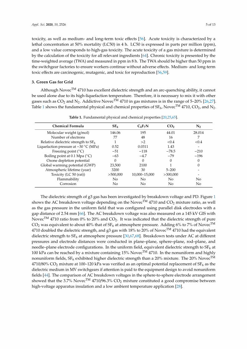
Although NovecTM 4710 has excellent dielectric strength and an arc-quenching ability, it cannotbe used alone due to its high-liquefaction temperature. Therefore, it is necessary to mix it with othergases such as CO2 and N2. Addictive NovecTM 4710 in gas mixtures is in the range of 5–20% [26,27].Table 1 shows the fundamental physical and chemical properties of SF6, NovecTM 4710, CO2, and N2.
Table 1. Fundamental physical and chemical properties [20,25,65].
Chemical Formula SF6 C4F7N CO2 N2
Molecular weight (g/mol) 146.06 195 44.01 28.014Number of electrons 77 48 16 7
Relative dielectric strength to SF6 1 >2 <0.4 <0.4Liquefaction pressure at −30 ◦C (MPa) 0.52 0.0311 1.43 -
Freezing point (◦C) −51 −118 −78.5 −210Boiling point at 0.1 Mpa (◦C) −63 −4.7 −79 −196
Ozone depletion potential 0 0 0 0Global warming potential (GWP) 23,500 2100 1 0
Atmospheric lifetime (year) 3200 30 5–200 -Toxicity (LC 50 (rat)) >500,000 10,000–15,000 >300,000 -
Flammability No No No NoCorrosion No No No No
The dielectric strength of g3 gas has been investigated by breakdown voltage and PD. Figure 1shows the AC breakdown voltage depending on the NovecTM 4710 and CO2 mixture ratio, as wellas the gas pressure in the uniform field that was configured using parallel disk electrodes with agap distance of 2.54 mm [66]. The AC breakdown voltage was also measured on a 145 kV GIS withNovecTM 4710 ratio from 0% to 20% and CO2. It was indicated that the dielectric strength of pureCO2 was equivalent to about 40% that of SF6 at atmosphere pressure. Adding 6% to 7% of NovecTM
4710 doubled the dielectric strength, and g3 gas with 18% to 20% of NovecTM 4710 had the equivalentdielectric strength to SF6 at atmosphere pressure [30,67,68]. Breakdown tests under AC at differentpressures and electrode distances were conducted in plane–plane, sphere–plane, rod–plane, andneedle–plane electrode configurations. In the uniform field, equivalent dielectric strength to SF6 at100 kPa can be reached by a mixture containing 15% NovecTM 4710. In the nonuniform and highlynonuniform fields, SF6 exhibited higher dielectric strength than a 20% mixture. The 20% NovecTM
4710/80% CO2 mixture at 100–120 kPa was verified as an optimal potential replacement of SF6 as thedielectric medium in MV switchgears if attention is paid to the equipment design to avoid nonuniformfields [44]. The comparison of AC breakdown voltages in the sphere-to-sphere electrode arrangementshowed that the 3.7% NovecTM 4710/96.3% CO2 mixture constituted a good compromise betweenhigh-voltage apparatus insulation and a low ambient temperature application [28].

Appl. Sci. 2020, 10, 2526 6 of 13Appl. Sci. 2020, 10, x FOR PEER REVIEW 6 of 13
Figure 1. AC breakdown voltage depending mixture ratio and gas pressure [66].
The positive and negative DC breakdown tests were carried out in a plane–plane electrode arrangement. As shown in Figure 2, the negative DC breakdown strengths of 4% NovecTM 4710/96% CO2 and 8% NovecTM 4710/92% CO2 mixtures at 0.7 MPa were 81.21% and 96.48% of the value for SF6 at 0.5 MPa [57,69]. The lightning breakdown voltages of 3.7% NovecTM 4710/96.3% CO2 at pressures of 0.88 MPa and 1.04 MPa were almost equivalent to that of SF6 at 0.55 MPa and 0.65 MPa, respectively [28].
Figure 2. DC breakdown strength of the NovecTM 4710/carbon dioxide (CO2) mixture depending on gas ratio and pressure [57].
PDIVs of SF6 and NovecTM 4710/CO2 were measured in protrusions on the conductor and enclosure of GIS. As shown in Figure 3, PDIVs in g3 gas with 4% NovecTM 4710/96% CO2 in protrusion defects were measured as 76–84% of that of SF6. In addition, the average apparent charge and pulse count of PD in g3 were higher compared with those in SF6 [70]. The PDIV in NovecTM 4710/N2 showed that the dielectric strength of the gas mixture was weaker than that of pure SF6 [27].
Figure 1. AC breakdown voltage depending mixture ratio and gas pressure [66].
The positive and negative DC breakdown tests were carried out in a plane–plane electrodearrangement. As shown in Figure 2, the negative DC breakdown strengths of 4% NovecTM 4710/96%CO2 and 8% NovecTM 4710/92% CO2 mixtures at 0.7 MPa were 81.21% and 96.48% of the valuefor SF6 at 0.5 MPa [57,69]. The lightning breakdown voltages of 3.7% NovecTM 4710/96.3% CO2 atpressures of 0.88 MPa and 1.04 MPa were almost equivalent to that of SF6 at 0.55 MPa and 0.65 MPa,respectively [28].
Appl. Sci. 2020, 10, x FOR PEER REVIEW 6 of 13
Figure 1. AC breakdown voltage depending mixture ratio and gas pressure [66].
The positive and negative DC breakdown tests were carried out in a plane–plane electrode arrangement. As shown in Figure 2, the negative DC breakdown strengths of 4% NovecTM 4710/96% CO2 and 8% NovecTM 4710/92% CO2 mixtures at 0.7 MPa were 81.21% and 96.48% of the value for SF6 at 0.5 MPa [57,69]. The lightning breakdown voltages of 3.7% NovecTM 4710/96.3% CO2 at pressures of 0.88 MPa and 1.04 MPa were almost equivalent to that of SF6 at 0.55 MPa and 0.65 MPa, respectively [28].
Figure 2. DC breakdown strength of the NovecTM 4710/carbon dioxide (CO2) mixture depending on gas ratio and pressure [57].
PDIVs of SF6 and NovecTM 4710/CO2 were measured in protrusions on the conductor and enclosure of GIS. As shown in Figure 3, PDIVs in g3 gas with 4% NovecTM 4710/96% CO2 in protrusion defects were measured as 76–84% of that of SF6. In addition, the average apparent charge and pulse count of PD in g3 were higher compared with those in SF6 [70]. The PDIV in NovecTM 4710/N2 showed that the dielectric strength of the gas mixture was weaker than that of pure SF6 [27].
Figure 2. DC breakdown strength of the NovecTM 4710/carbon dioxide (CO2) mixture depending ongas ratio and pressure [57].
PDIVs of SF6 and NovecTM 4710/CO2 were measured in protrusions on the conductor andenclosure of GIS. As shown in Figure 3, PDIVs in g3 gas with 4% NovecTM 4710/96% CO2 in protrusiondefects were measured as 76–84% of that of SF6. In addition, the average apparent charge and pulsecount of PD in g3 were higher compared with those in SF6 [70]. The PDIV in NovecTM 4710/N2 showedthat the dielectric strength of the gas mixture was weaker than that of pure SF6 [27].

Appl. Sci. 2020, 10, 2526 7 of 13Appl. Sci. 2020, 10, x FOR PEER REVIEW 7 of 13
Figure 3. Partial discharge inception voltages of SF6 and g3 in the protrusion defects [70].
The switching bus-transfer current test was carried out on a 420 kV disconnector over a 100 close and open operation under 1600 A and 20 V. Comparison of the arcing time between NovecTM 4710/CO2 gas mixture and SF6 is shown in Figure 4. It indicates that the arcing time of g3 gas proved to be stable, and the average arcing time is about 12 ms, compared with a typical value of 15 ms for SF6. [67]. The arc-quenching capability was verified according to IEC 62271-100, also indicating that g3 gas maintained the appropriate dielectric withstanding ability after repeated interruptions [68,71,72].
Figure 4. Arcing time of NovecTM 4710/CO2 gas mixture and SF6 [26].
Temperature rise tests of g3 gas were performed on a fully equipped three-phase GIS bay, and the results are shown in Figure 5. There were temperature rise differences of 5 K to 6 K between the gas mixtures and SF6 [26,67]. The temperature rise can be compensated for by typical measures such as adding cooling fins to the enclosure or machining slots and holes to conductors to improve convection around live parts of the GIS.
Figure 3. Partial discharge inception voltages of SF6 and g3 in the protrusion defects [70].
The switching bus-transfer current test was carried out on a 420 kV disconnector over a 100 closeand open operation under 1600 A and 20 V. Comparison of the arcing time between NovecTM 4710/CO2
gas mixture and SF6 is shown in Figure 4. It indicates that the arcing time of g3 gas proved to bestable, and the average arcing time is about 12 ms, compared with a typical value of 15 ms for SF6 [67].The arc-quenching capability was verified according to IEC 62271-100, also indicating that g3 gasmaintained the appropriate dielectric withstanding ability after repeated interruptions [68,71,72].
Appl. Sci. 2020, 10, x FOR PEER REVIEW 7 of 13
Figure 3. Partial discharge inception voltages of SF6 and g3 in the protrusion defects [70].
The switching bus-transfer current test was carried out on a 420 kV disconnector over a 100 close and open operation under 1600 A and 20 V. Comparison of the arcing time between NovecTM 4710/CO2 gas mixture and SF6 is shown in Figure 4. It indicates that the arcing time of g3 gas proved to be stable, and the average arcing time is about 12 ms, compared with a typical value of 15 ms for SF6. [67]. The arc-quenching capability was verified according to IEC 62271-100, also indicating that g3 gas maintained the appropriate dielectric withstanding ability after repeated interruptions [68,71,72].
Figure 4. Arcing time of NovecTM 4710/CO2 gas mixture and SF6 [26].
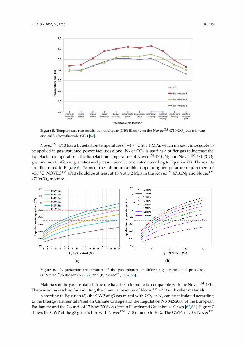
Temperature rise tests of g3 gas were performed on a fully equipped three-phase GIS bay, and the results are shown in Figure 5. There were temperature rise differences of 5 K to 6 K between the gas mixtures and SF6 [26,67]. The temperature rise can be compensated for by typical measures such as adding cooling fins to the enclosure or machining slots and holes to conductors to improve convection around live parts of the GIS.
Figure 4. Arcing time of NovecTM 4710/CO2 gas mixture and SF6 [26].
Temperature rise tests of g3 gas were performed on a fully equipped three-phase GIS bay, and theresults are shown in Figure 5. There were temperature rise differences of 5 K to 6 K between the gasmixtures and SF6 [26,67]. The temperature rise can be compensated for by typical measures such asadding cooling fins to the enclosure or machining slots and holes to conductors to improve convectionaround live parts of the GIS.
Appl. Sci. 2020, 10, 2526 8 of 13Appl. Sci. 2020, 10, x FOR PEER REVIEW 8 of 13
Figure 5. Temperature rise results in switchgear (GIS) filled with the NovecTM 4710/CO2 gas mixture
and sulfur hexafluoride (SF6) [67].
NovecTM 4710 has a liquefaction temperature of −4.7 °C at 0.1 MPa, which makes it impossible to be applied in gas-insulated power facilities alone. N2 or CO2 is used as a buffer gas to increase the liquefaction temperature. The liquefaction temperature of NovecTM 4710/N2 and NovecTM 4710/CO2 gas mixture at different gas ratios and pressures can be calculated according to Equation (1). The results are illustrated in Figure 6. To meet the minimum ambient operating temperature requirement of −30 °C, NOVECTM 4710 should be at least at 13% at 0.2 Mpa in the NovecTM 4710/N2 and NovecTM 4710/CO2 mixture.
(a) (b)
Figure 6. Liquefaction temperature of the gas mixture at different gas ratios and pressures. (a) NovecTM/Nitrogen (N2) [27] and (b) NovecTM/CO2 [58].
Materials of the gas-insulated structure have been found to be compatible with the NovecTM 4710. There is no research so far indicting the chemical reaction of NovecTM 4710 with other materials.
According to Equation (3), the GWP of g3 gas mixed with CO2 or N2 can be calculated according to the Intergovernmental Panel on Climate Change and the Regulation No 842/2006 of the European Parliament and the Council of 17 May 2006 on Certain Fluorinated Greenhouse Gases [62,63]. Figure 7 shows the GWP of the g3 gas mixture with NovecTM 4710 ratio up to 20%. The GWPs of 20% NovecTM 4710/80% CO2 and NovecTM 4710/80% N2 are 1104 and 1334, which are only 4.7% and 5.7% that of SF6, respectively. Therefore, the application of g3 gas results in a significant reduction in GWP.
Figure 5. Temperature rise results in switchgear (GIS) filled with the NovecTM 4710/CO2 gas mixtureand sulfur hexafluoride (SF6) [67].
NovecTM 4710 has a liquefaction temperature of −4.7 ◦C at 0.1 MPa, which makes it impossible tobe applied in gas-insulated power facilities alone. N2 or CO2 is used as a buffer gas to increase theliquefaction temperature. The liquefaction temperature of NovecTM 4710/N2 and NovecTM 4710/CO2
gas mixture at different gas ratios and pressures can be calculated according to Equation (1). The resultsare illustrated in Figure 6. To meet the minimum ambient operating temperature requirement of−30 ◦C, NOVECTM 4710 should be at least at 13% at 0.2 Mpa in the NovecTM 4710/N2 and NovecTM
4710/CO2 mixture.
Appl. Sci. 2020, 10, x FOR PEER REVIEW 8 of 13
Figure 5. Temperature rise results in switchgear (GIS) filled with the NovecTM 4710/CO2 gas mixture
and sulfur hexafluoride (SF6) [67].
NovecTM 4710 has a liquefaction temperature of −4.7 °C at 0.1 MPa, which makes it impossible to be applied in gas-insulated power facilities alone. N2 or CO2 is used as a buffer gas to increase the liquefaction temperature. The liquefaction temperature of NovecTM 4710/N2 and NovecTM 4710/CO2 gas mixture at different gas ratios and pressures can be calculated according to Equation (1). The results are illustrated in Figure 6. To meet the minimum ambient operating temperature requirement of −30 °C, NOVECTM 4710 should be at least at 13% at 0.2 Mpa in the NovecTM 4710/N2 and NovecTM 4710/CO2 mixture.
(a) (b)
Figure 6. Liquefaction temperature of the gas mixture at different gas ratios and pressures. (a) NovecTM/Nitrogen (N2) [27] and (b) NovecTM/CO2 [58].
Materials of the gas-insulated structure have been found to be compatible with the NovecTM 4710. There is no research so far indicting the chemical reaction of NovecTM 4710 with other materials.
According to Equation (3), the GWP of g3 gas mixed with CO2 or N2 can be calculated according to the Intergovernmental Panel on Climate Change and the Regulation No 842/2006 of the European Parliament and the Council of 17 May 2006 on Certain Fluorinated Greenhouse Gases [62,63]. Figure 7 shows the GWP of the g3 gas mixture with NovecTM 4710 ratio up to 20%. The GWPs of 20% NovecTM 4710/80% CO2 and NovecTM 4710/80% N2 are 1104 and 1334, which are only 4.7% and 5.7% that of SF6, respectively. Therefore, the application of g3 gas results in a significant reduction in GWP.
Figure 6. Liquefaction temperature of the gas mixture at different gas ratios and pressures.(a) NovecTM/Nitrogen (N2) [27] and (b) NovecTM/CO2 [58].
Materials of the gas-insulated structure have been found to be compatible with the NovecTM 4710.There is no research so far indicting the chemical reaction of NovecTM 4710 with other materials.
According to Equation (3), the GWP of g3 gas mixed with CO2 or N2 can be calculated accordingto the Intergovernmental Panel on Climate Change and the Regulation No 842/2006 of the EuropeanParliament and the Council of 17 May 2006 on Certain Fluorinated Greenhouse Gases [62,63]. Figure 7shows the GWP of the g3 gas mixture with NovecTM 4710 ratio up to 20%. The GWPs of 20% NovecTM

Appl. Sci. 2020, 10, 2526 9 of 13
4710/80% CO2 and NovecTM 4710/80% N2 are 1104 and 1334, which are only 4.7% and 5.7% that of SF6,respectively. Therefore, the application of g3 gas results in a significant reduction in GWP.Appl. Sci. 2020, 10, x FOR PEER REVIEW 9 of 13
Figure 7. Global warming potential of g3 gas mixture.
In addition, g3 gas has an ODP of zero, and its atmospheric lifetime is much shorter than that of SF6. g3 is not a carcinogenic and mutagenic gas, and is classified as nontoxic, nonflammable, and nonexplosive [61,70].
g3 gas has been verified as an effective and high-performance substitute of SF6 for environmentally sustainable high-voltage applications. At present, g3 gas-insulated power facilities are commercially available for GIS up to 145 kV, GIL and GCB up to 420 kV, and GIT up to 245 kV, after stringent laboratory and equipment testing [30]. These facilities feature the same dimensional footprint as SF6 equipment, while significantly reducing greenhouse gas emissions.
4. Conclusions
As a new potential alternative insulation gas to SF6, g3 that is composed of NovecTM 4710 and CO2 or N2 shows its high performance as an insulation medium of gas-insulated power facilities. This paper presents a comprehensive overview of g3 gas for applications in high-voltage, gas-insulated equipment, and conclusions are as follows:
1. From the AC/DC breakdown voltage and partial discharge characteristics, the addition of a few ratios of NovecTM 4710 to the buffer gas significantly increases the dielectric strength of the gas mixture, which is almost equivalent to that of SF6.
2. At the same time, g3 presents a good compromise between high dielectric strength and low ambient temperature requirements, which met the requirement of the minimum ambient operating temperature of power facilities.
3. In addition, the switching bus-transfer current test, temperature rise test, and liquefaction temperature calculation also verified the validity of g3 gas for high-voltage insulation applications.
4. As for environmental concerns, g3 gas reduces the GWP of more than 94% compared with SF6. It has an ODP of zero and an atmospheric lifetime as short as 30 years, which is only 1% of that of SF6.
From the laboratory and equipment testing, g3 is verified as the most promising eco-friendly alternative insulation gas to SF6 developed for the SF6-free gas-insulated power facilities. It is a potential alternative for electrical equipment with a drastically reduced environmental impact while featuring the same structure, operation, ratings, and footprint of existing equipment.
Author Contributions: Conceptualization, B.P., G.W., and H.S.; methodology, B.P., H.S., J.S., and H.-K.J.; validation, G.W., J.S., and H.-K.J.; formal analysis, J.S. and G.-S.K.; investigation, H.S., J.S., and H.-K.J.; writing—original draft preparation, B.P. and G.W.; writing—review and editing, H.S. and H.-K.J.; supervision, J.S. and G.-S.K.; project administration, G.W. All authors have read and agreed to the published version of the manuscript.
Funding: This research received no external funding.
Figure 7. Global warming potential of g3 gas mixture.
In addition, g3 gas has an ODP of zero, and its atmospheric lifetime is much shorter than thatof SF6. g3 is not a carcinogenic and mutagenic gas, and is classified as nontoxic, nonflammable,and nonexplosive [61,70].
g3 gas has been verified as an effective and high-performance substitute of SF6 for environmentallysustainable high-voltage applications. At present, g3 gas-insulated power facilities are commerciallyavailable for GIS up to 145 kV, GIL and GCB up to 420 kV, and GIT up to 245 kV, after stringentlaboratory and equipment testing [30]. These facilities feature the same dimensional footprint as SF6
equipment, while significantly reducing greenhouse gas emissions.
4. Conclusions
As a new potential alternative insulation gas to SF6, g3 that is composed of NovecTM 4710 andCO2 or N2 shows its high performance as an insulation medium of gas-insulated power facilities.This paper presents a comprehensive overview of g3 gas for applications in high-voltage, gas-insulatedequipment, and conclusions are as follows:
1. From the AC/DC breakdown voltage and partial discharge characteristics, the addition of a fewratios of NovecTM 4710 to the buffer gas significantly increases the dielectric strength of the gasmixture, which is almost equivalent to that of SF6.
2. At the same time, g3 presents a good compromise between high dielectric strength and lowambient temperature requirements, which met the requirement of the minimum ambient operatingtemperature of power facilities.
3. In addition, the switching bus-transfer current test, temperature rise test, and liquefactiontemperature calculation also verified the validity of g3 gas for high-voltage insulation applications.
4. As for environmental concerns, g3 gas reduces the GWP of more than 94% compared with SF6.It has an ODP of zero and an atmospheric lifetime as short as 30 years, which is only 1% of thatof SF6.
From the laboratory and equipment testing, g3 is verified as the most promising eco-friendlyalternative insulation gas to SF6 developed for the SF6-free gas-insulated power facilities. It is apotential alternative for electrical equipment with a drastically reduced environmental impact whilefeaturing the same structure, operation, ratings, and footprint of existing equipment.

Appl. Sci. 2020, 10, 2526 10 of 13
Author Contributions: Conceptualization, B.P., G.W., and H.S.; methodology, B.P., H.S., J.S., and H.-K.J.; validation,G.W., J.S., and H.-K.J.; formal analysis, J.S. and G.-S.K.; investigation, H.S., J.S., and H.-K.J.; writing—original draftpreparation, B.P. and G.W.; writing—review and editing, H.S. and H.-K.J.; supervision, J.S. and G.-S.K.; projectadministration, G.W. All authors have read and agreed to the published version of the manuscript.
Funding: This research received no external funding.
Conflicts of Interest: The authors declare no conflict of interest.
References
1. Beroual, A.; Haddad, A. Recent advances in the quest for a new insulation gas with a low impact on theenvironment to replace sulfur hexafluoride (SF6) gas in high-voltage power network applications. Energies2017, 10, 1216. [CrossRef]
2. Li, X.; Zhao, H.; Murphy, A.B. SF6-alternative gases for application in gas-insulated switchgear. J. Phys. D:Appl. Phys. 2018, 51, 153001. [CrossRef]
3. Haddad, A.; Warne, D.F. Advances in High Voltage Engineering, 1st ed.; The Institution of Engineering andTechnology: Stevenage, UK, 2004; pp. 37–73. [CrossRef]
4. Zhao, S.; Xiao, D.; Xue, P.; Zhong, R.; Deng, Y. Analysis of insulation performance and polar effect ofCF3I/CO2 mixtures. IEEE Trans. Dielectr. Electr. Insul. 2018, 25, 1364–1370. [CrossRef]
5. Glaubitz, P.; Stangherlin, S.; Biasse, J.M.; Meyer, F.; Dallet, M.; Prufert, M.; Kurte, R.; Saida, T.; Uehara, K.;Prieur, P.; et al. CIGRE position paper on the application of SF6 in transmission and distribution networks.ELECTRA 2014, 274, 34–39.
6. Wang, G.M.; Kil, G.S. Measurement and analysis of partial discharge using an ultra-high frequency sensorfor gas insulated structures. Metrol. Meas. Syst. 2017, 24, 515–524. [CrossRef]
7. Western Power Distribution. SF6 Alternatives—A Literature Review on SF6 Gas Alternatives for Use on theDistribution Network; Western Power Distribution: Wales, UK, 2018; pp. 6–39.
8. United Nations. Kyoto Protocol to the United Nations Framework Convention on Climate Change; United Nations:Rome, Italy, 1998; pp. 1–19.
9. United Nations. Paris Agreement—United Nations Framework Convention on Climate Change; United Nations:Rome, Italy, 2015.
10. Okubo, H.; Beroual, A. Recent trend and future perspectives in electrical insulation techniques in relation tosulfur hexafluoride (SF6) substitutes for high voltage electric power equipment. IEEE Electr. Insul. Mag.2011, 27, 34–42. [CrossRef]
11. Widger, P.; Haddad, A. Evaluation of SF6 leakage from gas insulated equipment on electricity networks inGreat Britain. Energies 2018, 11, 2037. [CrossRef]
12. Christophorou, L.G.; Olthoff, J.K.; Brunt, R.J.V. Sulfur hexafluoride and the electric power industry. IEEE Electr.Insul. Mag. 1997, 13, 20–24. [CrossRef]
13. Kieffel, Y.; Biquez, F.; Ponchon, P. Alternative gas to SF6 for use in high voltage switchgears: G3. In Proceedingsof the International Conference on Electricity Distribution, Lyon, France, 15–18 June 2015; pp. 1–5.
14. Zhao, S.; Xiao, D.; Xue, P.; Zhong, R.; Deng, Y. Experimental research on polarity effect of CF3I/N2 mixtureunder lightning impulse. IEEE Trans. Dielectr. Electr. Insul. 2018, 25, 1357–1363. [CrossRef]
15. European Environment Agency. Regulation (EU) No 517/2014 of the European parliament and of the councilof 16 April 2014 on fluorinated greenhouse gases and repealing Regulation (EC) No 842/2006 text with EEArelevance. Off. J. Eur. Union 2014, 150, 195–230.
16. Department for Environment. Food & Rural Affairs and Environment Agency (DEFRA) of UK Government.Calculate the Carbon Dioxide Equivalent Quantity of an F gas; UK Government: London, UK.
17. Dervos, T.C.; Vassiliou, P. Sulfur hexafluoride(SF6): Global environmental effects and toxic byproductformation. J. Air Waste Manag. Assoc. 1995, 50, 137–141. [CrossRef] [PubMed]
18. Tsai, W.T. The decomposition products of sulfur hexafluoride (SF6): Reviews of environmental and healthrisk analysis. J. Fluor. Chem. 2007, 128, 1345–1352. [CrossRef]
19. Goshima, H.; Tanimura, A.; Tsuru, S.; Yaegashi, Y.; Fujie, E.; Okubo, H. Fundamental insulation characteristicsof high-pressure CO2 gas under actual equipment conditions. IEEE Trans. Dielectr. Electr. Insul. 2007, 14,83–90. [CrossRef]
Appl. Sci. 2020, 10, 2526 11 of 13
20. Rokunohe, T.; Yagihashi, Y.; Endo, F.; Oomori, T. Fundamental insulation characteristics of air, N2, CO2,N2/O2, and SF6/N2 mixed gases. Electr. Eng. Jpn. 2006, 155, 9–17. [CrossRef]
21. Qiu, Y.; Kuffel, E. Comparison of SF6/N2 and SF6/CO2 gas mixtures as alternatives to SF6 gas. IEEE Trans.Dielectr. Electr. Insul. 1999, 6, 891–895. [CrossRef]
22. Beroual, A.; Khaled, U.; Coulibaly, M.L. Experimental investigation of the breakdown voltage of CO2, N2,and SF6 gases, and CO2–SF6 and N2–SF6 mixtures under different voltage waveforms. Energies 2018, 11, 902.[CrossRef]
23. Katagiri, H.; Kasuya, H.; Mizoguchi, H.; Yanabu, S. Investigation of the performance of CF3I gas as a possiblesubstitute for SF6. IEEE Trans. Dielectr. Electr. Insul. 2008, 15, 1424–1429. [CrossRef]
24. McCain, W.C.; Macko, J. Toxicity review for iodotrifluoromethane (CF3I). In Proceedings of the HalonOptions Technical Working Conference, Albuquerque, NM, USA, 17–29 April 1999; pp. 242–253.
25. Hikita, M.; Ohtsuka, S.; Okabe, S.; Kaneko, S. Insulation characteristics of gas mixtures includingperfluorocarbon gas. IEEE Trans. Dielectr. Electr. Insul. 2008, 15, 1015–1022. [CrossRef]
26. Kieffel, Y.; Biquez, F. SF6 alternative development for high voltage switchgears. In Proceedings of theElectrical Insulation Conference, Washington, DC, USA, 7–10 June 2015; pp. 379–383. [CrossRef]
27. Li, Y.; Zhang, X.; Chen, Q.; Fu, M.; Zhuo, R.; Xiao, S.; Chen, D.; Tang, J. Study on the dielectric properties ofC4F7N/N2 mixture under highly non-uniform electric field. IEEE Access 2018, 6, 42868–42875. [CrossRef]
28. Nechmi, H.E.; Beroual, A.; Girodet, A.; Vinson, P. Fluoronitriles/CO2 gas mixture as promising substituteto SF6 for insulation in high voltage applications. IEEE Trans. Dielectr. Electr. Insul. 2016, 23, 2587–2593.[CrossRef]
29. Seeger, M.; Smeets, R.; Yan, J.; Ito, H.; Claessens, M.; Dullni, E.; Franck, C.M.; Gentils, F.; Hartmann, W.;Kieffel, Y.; et al. Recent development of alternative gases to SF6 for switching applications. ELECTRA 2017,291, 26–29.
30. Kieffel, Y.; Irwin, T.; Ponchon, P.; Owens, J. Green gas to replace SF6 in electrical grids. IEEE Power Energy Mag.2014, 14, 32–39. [CrossRef]
31. Malik, N.H.; Al-Arainy, A.A.; Qureshi, M.I. Electrical Insulation in Power System, 1st ed.; MARCEL DEKKER:New York, NY, USA, 1997; pp. 1–110.
32. Ryan, H.M. High-Voltage Engineering and Testing, 3rd ed.; The Institution of Engineering and Technology:Stevenage, UK, 2003; pp. 631–674. [CrossRef]
33. Hoshina, Y.; Sato, M.; Shiiki, M.; Hanai, M.; Kaneko, E. Lightning impulse breakdown characteristics of SF6
alternative gases for gas-insulated switchgear. IEE Proc. Sci. Meas. Technol. 2006, 153, 1–6. [CrossRef]34. Cookson, A.H. Review of high-voltage gas breakdown and insulators in compressed gas. IEE Proc. Phys. Sci.
Meas. Instr. Manag. Educ. 1981, 128, 303–312. [CrossRef]35. Radmilovic-Radjenovic, M.; Lee, J.K.; Iza, F.; Park, G.Y. Particle-in-cell simulation of gas breakdown in
microgaps. J. Phys. D: Appl. Phys. 2005, 38, 950–954. [CrossRef]36. Christophorou, L.G.; Olthoff, J.K.; Greem, D.S. Gases for Electrical Insulation and Arc Interruption: Possible Present
and Future Alternatives to Pure SF6; United States Department of Commerce Technology Administration,National Institute of Standards and Technology: Maryland, MD, USA, 1997; pp. 1–29.
37. Laghari, J.R.; Qureshi, A.H. A review of particle-contaminated gas breakdown. IEEE Trans. Dielectr.Electr. Insul. 1981, 16, 388–398. [CrossRef]
38. International Electrotechnical Commission. High-Voltage Test Techniques-Partial Discharge Measurements; IEC60270; IEC: Geneva, Switzerland, 2015.
39. Wang, G.M.; Kim, S.J.; Kil, G.S.; Kim, S.W. Optimization of wavelet and thresholding for partial dischargedetection under HVDC. IEEE Trans. Dielectr. Electr. Insul. 2017, 24, 200–208. [CrossRef]
40. Wang, G.M.; Jo, H.E.; Kim, S.J.; Kim, S.W.; Kil, G.S. Measurement and analysis of partial discharges in SF6
gas under HVDC. Measurement 2016, 91, 351–359. [CrossRef]41. Okubo, H.; Yamada, T.; Takahashi, T.; Toda, T. Partial discharge inception and breakdown characteristics in
gas mixtures with SF6. In Gaseous Dielectrics VIII, 1st ed.; Christophorou, L.G., Olthoff, J.K., Eds.; Springer:Boston, MA, USA, 1998; pp. 289–294.
42. Zhang, B.; Uzelac, N.; Cao, Y. Fluoronitrile/CO2 Mixture as an eco-friendly alternative to SF6 for mediumvoltage switchgears. IEEE Trans. Dielectr. Electr. Insul. 2018, 25, 1340–1350. [CrossRef]
43. Wang, G.M.; Kil, G.S.; Ji, H.G.; Lee, J.H. Disturbance elimination for partial discharge detection in the spacerof gas-insulated switchgears. Energies 2017, 10, 1762. [CrossRef]
Appl. Sci. 2020, 10, 2526 12 of 13
44. Okubo, H.; Yamada, T.; Hatta, K.; Hayakawa, N.; Yuasa, S.; Okabe, S. Partial discharge and breakdownmechanisms in ultra-dilute SF6 and PFC gases mixed with N2 gas. J. Phys. D: Appl. Phys. 2002, 35, 2760–2765.[CrossRef]
45. Taki, M.; Maekawa, D.; Odaka, H.; Mizoguchi, H.; Yanabu, S. Interruption capability of CF3I gas as asubstitution candidate for SF6 gas. IEEE Trans. Dielectr. Electr. Insul. 2007, 14, 341–346. [CrossRef]
46. Kosse, S.; Nikolic, P.G.; Kachelriess, G. Holistic evaluation of the performance of today’s SF6 alternativesproposals. In Proceedings of the International Conference & Exhibition on Electricity Distribution, Glasgow,UK, 12–15 June 2017; pp. 210–213. [CrossRef]
47. Xiao, S.; Zhang, X.; Tang, J.; Liu, S. A review on SF6 substitute gases and research status of CF3I gases.Energy Rep. 2018, 4, 486–496. [CrossRef]
48. Smeets, R.P.P.; Kertész, V.; Nishiwaki, S.; Suzuki, K. Performance evaluation of high-voltage circuit breakersby means of current zero analysis. In Proceedings of the IEEE/PES Transmission and Distribution Conferenceand Exhibition, Yokohama, Japan, 6–10 October 2002; pp. 424–429. [CrossRef]
49. Ahmethodzic, A.; Smeets, R.P.P.; Kertész, V.; Kapetanovic, M.; Sokolija, K. Design improvement of a 245-kVSF6 circuit breaker with double-speed mechanism through current zero analysis. IEEE Trans. Power Del.2010, 25, 2496–2503. [CrossRef]
50. Petchanka, A.; Reichert, F.; Gonzalez, J.J.; Freton, P. Modelling of the deformation of PTFE-nozzles in a highvoltage circuit breaker due to multiple interruptions. J. Phys. D Appl. Phys. 2016, 49, 135201. [CrossRef]
51. Novák, B. Comparison of heat transfer in air and SF6 in high voltage GIS. In Proceedings of the ElectricalInsulation Conference, Ottawa, ON, Canada, 2–5 June 2013; pp. 85–89. [CrossRef]
52. Novák, B.; Koller, L. Steady-state heating of gas insulated busbars. In Proceedings of the IEEE/PESTransmission and Distribution Conference and Exhibition, Orlando, FL, USA, 7–10 May 2012; pp. 1–7.[CrossRef]
53. International Electrotechnical Commission. High-Voltage Switchgear and Controlgear-Part 1: CommonSpecifications for Alternating Current Switchgear and Controlgear; IEC 62271-1; IEC: Geneva, Switzerland, 2017.
54. Chen, G.; Tu, Y.; Wang, C.; Cheng, Y.; Jiang, H.; Zhou, H.; Jin, H. Analysis on temperature distribution andcurrent-carrying capacity of GIL filled with Fluoronitriles-CO2 gas mixture. J. Electr. Eng. Technol. 2018, 13,2402–2411. [CrossRef]
55. Institute of Electrical and Electronics Engineers. IEEE Standard of Common Requirements for High Voltage PowerSwitchgear Rated Above 1000V; IEEE C37.100.1; IEEE: New York, NY, USA, 2018.
56. Preve, C.; Piccoz, D.; Maladen, R. Validation methods of SF6 alternative gas. In Proceedings of theInternational Conference on Electricity Distribution, Lyon, French, 15–18 June 2015; pp. 1–5.
57. Wang, C.; Cheng, Y.; Tu, Y.; Chen, G.; Yuan, Z.; Xiao, A.; Owens, J.; Zhang, A.; Mi, N. Characteristics ofC3F7CN/CO2 as an alternative to SF6 in HVDC-GIL systems. IEEE Trans. Dielectr. Electr. Insul. 2018, 25,1351–1356. [CrossRef]
58. Zhang, X.; Chen, Q.; Zhang, J.; Li, Y.; Xiao, S.; Zhuo, R.; Tang, J. Experimental study on power frequencybreakdown characteristics of C4F7N/CO2 gas mixture under quasi-homogeneous electric field. IEEE Access2019, 7, 19100–19108. [CrossRef]
59. Hyrenbach, M.; Zache, S. Alternative insulation gas for medium-voltage switchgear. In Proceedings of thePetroleum and Chemical Industry Conference Europe, Berlin, Germany, 14–16 June 2016. [CrossRef]
60. Intergovernmental Panel on Climate Change. Climate Change 2013; Cambridge University Press: New York,NY, USA, 2013; pp. 159–254.
61. Owens, J.G. Greenhouse gas emission reductions through use of a sustainable alternative to SF6.In Proceedings of the IEEE Electrical Insulation Conference, Montreal, QC, Canada, 19–22 June 2016;pp. 535–538. [CrossRef]
62. European Environment Agency. Regulation (EC) No 842/2006 of the European parliament and of the councilof 17 May 2006 on certain fluorinated greenhouse gases. Off. J. Eur. Union 2006, 15, 1–11.
63. European Fluorocarbons Technical Committee. F Gas Regulation Implementation and Compliance.Available online: https://www.fluorocarbons.org/efctc-f-gas-regulation-implementation-compliance/
(accessed on 2 December 2019).
Appl. Sci. 2020, 10, 2526 13 of 13
64. European Environment Agency. Regulation (EC) No 1272/2008 of the European parliament and of the councilof 16 December 2008 on classification, labelling and packaging of substances and mixtures, amending andrepealing Directives 67/548/EEC and 1999/45/EC, and amending Regulation (EC) No 1907/2006. Off. J. Eur.Union 2008, 353, 1–50.
65. Rabie, M.; Franck, C.M. Assessment of eco-friendly gases for electrical insulation to replace the most potentindustrial greenhouse gas SF6. Environ. Sci. Technol. 2018, 52, 369–380. [CrossRef] [PubMed]
66. 3M Company. NovecTM 4710 Insulating Gas; 3M Company: Saint Paul, MN, USA, 2017.67. Kieffel, Y.; Girodet, A.; Biquez, F.; Ponchon, P.; Owens, J.; Costello, M.; Bulinski, M.; San, R.V.; Werner, K.
SF6 alternative development for high voltage switchgears. In Proceedings of the CIGRE 2014, Paris, France,24–29 August 2014.
68. Kieffel, Y.; Biquez, F.; Vigouroux, D. Characteristics of g3—An alternative to SF6. In Proceedings of theInternational Conference & Exhibition on Electricity Distribution, Glasgow, UK, 12–15 June 2017; pp. 54–57.[CrossRef]
69. Tu, Y.; Cheng, Y.; Wang, C.; Ai, X.; Zhou, F.; Chen, G. Insulation characteristics of fluoronitriles/CO2 gasmixture under DC electric field. IEEE Trans. Dielectr. Electr. Insul. 2018, 25, 1324–1331. [CrossRef]
70. Wang, G.M.; Kim, W.H.; Kil, G.K.; Kim, S.W.; Jung, J.R. Green gas for grid as an eco-friendly alternativeinsulation gas to SF6: From the perspective of partial discharge under AC. Appl. Sci. 2019, 9, 651. [CrossRef]
71. Wang, G.M.; Shen, J.H.; Liu, D.M.; Kim, S.W.; Kil, G.S. Green gas for grid as an eco-friendly alternativeinsulation gas to SF6: From the perspective of PD initiated by metallic particles under DC. J. Electr. Eng.2020, 1, 43–48. [CrossRef]
72. International Electrotechnical Commission. High-Voltage Switchgear and Controlgear—Part 100: AlternatingCurrent Circuit-Breakers; IEC 62271-100; IEC: Geneva, Switzerland, 2017.
© 2020 by the authors. Licensee MDPI, Basel, Switzerland. This article is an open accessarticle distributed under the terms and conditions of the Creative Commons Attribution(CC BY) license (http://creativecommons.org/licenses/by/4.0/).