Embed Size (px)
Citation preview

USACERL ADP Report N-92/01April 1992
CADD/GIS IntegrationUS Army Corpsof EngineersConstruction EngineeringResearch Laboatory AD-A251 458
GRASS-IntergraphData Conversion Guide
byVictoria HarmonDouglas M. YoungsMelissa A. Records
DTICELECTE
This guide outlines methods for bi-directionally JUN 17.1992translating vector data between IntergraphGraphics Design Software (IGDS) and the Geo-graphic Resources Analysis Support System(GRASS).
GRASS is a workstation and a microcomputer-based image-processing and geographic informa-tion system (GIS) used to develop, manipulate,analyze, and display geographic datasets. Sinceboth CADD and GRASS use digital spatial data(e.g., maps), this data translation capability cancreate joint applications between the two sys-tems.
This report describes the necessary translationpaths, data format organization, data editing, andprocedures to translate data between the twosystems.
92-15722Approved for public release; distribution is unlimited.ll lllllill
4

The contents of this report are not to be used for advertising, publication, orpromotional purposes. Citation of trade names does not constitute an officialendorsement or approval of the use of such commercial products. Thefindings of this report are not to be construed as an official Department ofthe Army position, unless so designated by other authorized documents.
DESTROY THIS REPORT WHEN IT IS NO LONGER NEEDEDDO NOT RETURN IT TO THE ORIGINATOR

DOCUMENTATION PAGEI Form ApprovedR DOMB No. 0704-0188
Public reporting burden for this colection of information Is estimated to average 1 hour per response, including the time for reviewing instruclions, searching existing data sources,gathering and maintaining the data needed. and completing aind reviewing the collection of information. Send comments regarding this burden estimate or any other aspect of this
collection of information, including suggestions for reducing this burden, to Washington Headquarters Services, Directorate for information Operations and Reports. 1215 Jefferson
Davis Highway, Suite 1204. Arlington. VA 22202-4302. and to the Office of Management and Budget. Paperwork Reduction Project (0704-0188), Washington, DC 20503.
1. AGENCY USE ONLY (Leave Blank) 2. REPORT DATE 3. REPORT TYPE AND DATES COVERED
4. TITLE AND SUBTITLE 5. FUNDING NUMBERS
GRASS-Intergraph Data Conversion Guide OMA-WY-PD9FAD 89-08037, Jan 1984
o. AUTHOR(S) WY-JM9 MIPRE8789L090, Oct 1989
Victoria Harmon, Douglas M. Youngs, and Melissa A. RecordsWU-RHO-FAD 90-080586, Feb 1990
7. PEqFORMING ORGANIZATION NAME(S) AND ADDRESS(ES) 8. PERFORMING ORGANIZATIONREPORT NUMBER
U.S. Army Construction Engineering Research Laboratory (USACERL)2902 Newmark Drive, PO Box 9005 ADP N-92/01
Champaign, IL 61826-9005
9. SPONSORING/MONITORING AGENCY NAME(S) AND ADDRESS(ES) 10. SPONSORING/MONITORINGAGENCY REPORT NUMBER
USA Engineering and Housing Support Center Chief Installations BrachATTN: CEHSC-F ATTN: DAEN-ZCI-PBldg 358 Rm IE671 PentagonFort Belvoir, VA 22060-5516 Washington DC 20310
1. SUPPLEMENTARY NOTES
Copies are available from the National Technical Information Service, 5285 Port Royal Road,Springfield, VA 22161
12a. DISTRIBUTION/AVAILABILITY STATEMENT 12b. DISTRIBUTION CODE
Approved for public release; distribution is unlimited.
13. ABSTRACT (Maximum 200 words)
This guide outlines methods for bi-directionally translating vector data between Intergraph GraphicsDesign Software (IGDS) and the Gecographic Resources Analysis Support System (GRASS).
GRASS is a microcomputer-based image-processing and geographic information system (GIS) used todevelop, manipulate, analyze, and display geographic dtasets. Since both CADD and GRASS use digitalspatial data (e.g., maps), this data translation capability can create joint applications between the twosystems.
This report describes the necessary translation paths, data format organization, data editing, andprocedures to translate data between the two systems.
14. SUBJECT TERMS 15 NUMBER OF PAGES
Geographic Resources Analysis Support System (GRASS) 60Intergraph CADD vector data 16. PRICE CODE
17 SECURITY CLASSIFICATION 18. SECURITY CLASSIFICATION 19. SECURITY CLASSIFICATION 20. LIMITATION OF ABSTRACTOF REPORT OF THIS PAGE OF ABSTRACT
Unclassi fied Unclassified Unclassified SAR
NSN 7540-01-280-5500 Stndard Form 298 (Re 2 89;Pnescibed by ANSI Std 239 IS298-1 02
FOREWORD
This study was done for the Office of the Chief of Engineers (OCE) and for the Engineering andHousing Support Center (EHSC), Fort Belvoir, VA. OCE funding was provided under the Operation andMaintenance, Army (OMA) project; Work Unit PD9, "CADD/GIS Integration"; Funding AcquisitionDocument (FAD) 89-08037, dated January 1989, and Work Unit JM9; Military Interdepartmental PurchaseRequest (MIPR) No. E8789L090, dated October 1989. EHSC funding was provided under Work UnitRHO; FAD 90-080586, dated February 1990. The OCE technical monitor was Mr. Stanley Shelton, ZCI-P,and the EHSC technical monitor was Mr. Donald Bandel, EHSC-FN.
This research was performed by the Environmental Division (EN) of the U.S. Army ConstructionEngineering Research Laboratory (USACERL). The principal investigators were Ms. Victoria Harmonand Mr. Douglas M. Youngs. Dr. Edward W. Novak is Acting Chief, USACERL-EN. The USACERLtechnical editor was Mr. William J. Wolfe, Information Management Office.
COL Daniel Waldo, Jr. is Commander and Director of USACERL, and Dr. L.R. Shaffer is TechnicalDirector.
Aec n For
NTIS GEA&IDTiC T.skE
By -.. -.
Dist
2

CONTENTSPage
SF298 1FOREWORD 2LIST OF TABLES AND FIGURES 5
INTRODUCTION ...................................................... 7BackgroundObjectiveApproachScopeMode of Technology Transfer
2 DIFFERENCES BETWEEN CADD AND GIS ................................ 9Functional DifferencesThe Intergraph CADD Mapping DatabaseThe Grass GIS Database
3 THE HARDWARE ENVIRONMENT ...................................... 15
4 ASPECTS OF IGDS MAPPING DATABASES THAT AFFECT TRANSLATION .... 17Digital IntegrityGlobal Origin and Coordinate RepresentationDesign File OrganizationDatabase DocumentationVisibility of Data Elements Depicting Map FeaturesGraphics StandardsAttached Reference Files and File CompressionData Redundancy and File Size
5 UNDERSTANDING THE IGDS MAPPING DATABASE ....................... 19IGDS Hardware EnvironmentsSome IGDS Analysis and Editing ToolsOrganization and Preliminary Data Analysis
6 TARGETING AND EDITING IGDS DATA ................................. 22Targeting DataEditing IGDS DataEditing GRASS DataAutomation PossibilitiesCheck Plots
7 INTERGRAPH TO GRASS VECTOR TRANSLATION PATHS .................. 25
8 CHOOSING DLG OR DXF AS AN INTERMEDIARY VECTOR FORMAT ........ 26When To Use Intergraph DLGOUTIntergraph dxfoutChapter Sumnary
3

CONTENTS (Cont'd)Page
9 EXPORTING DLG AND DXF FILES FROM INTERGRAPH .................. 29How To Run Intergraph VAX DLGOUTHow To Run Intergraph dxfout
10 IMPORTING DLG AND DXF FILES INTO GRASS ......................... 34How To Import DLG Files Into GRASSSummary of the IGDS-DLG-GRASS Translation SequenceHow To Import DXF Files Into GRASSSummary of the IGDS-DXF-GRASS Translation Sequence
11 COORDINATE CONVERSION IN GRASS ................................ 39
12 TRANSLATION ACCURACY ASSESSMENT .............................. 40
13 LABELING VECTOR FILES IN GRASS .................................. 41v.digitv.cadlabel
14 GUIDELINES FOR DIGITIZING MULTIPURPOSE IGDS DATA ............... 44
15 GRASS-INTERGRAPH DATABASE UPDATING ........................... 46
16 DOCUMENTATION OF IGDS DATA INTENDED FOR TRANSLATION ......... 48
17 GRASS-TO-INTERGRAPH VECTOR TRANSLATION PATHS ................. 49
18 CHOOSING DLG OR DXF AS AN INTERMEDIARY VECTOR FORMAT ........ 50GRASS Export ProgramsChapter Summary
19 EXPORTING DLG AND DXF FILES FROM GRASS ........................ 51How To Export DLG Files From GRASSSummary of the GRASS-DLG-IGDS Translation SequenceHow To Export DXF Files From GRASSSummary of the GRASS-DXF-IGDS Translation Sequence
20 IMPORTING DLG AND DXF FILES INTO IGDS ........................... 53How To Run Intergraph DLGINHow To Run Intergraph dxfin
REFERENCES 55
DISTRIBUTION
4

TABLES
Number Page
I Vector Data Themes 10
2 The Intergraph Vector Format 11
3 Target and Intermediate File sizes in Bytes 27
4 Advantages/Disadvantages of DLGOUT and dxfout 28
5 Vector Data Themes 46
6 Updating Capabilities 47
FIGURES
I Chanute AFB CAD Section Map 12
2 Schematic of a Mixed Hardware Environment 15
3 Intergraph-to-GRASS Vector Translation Paths 25
4 Label Menu 41
5 Label Contours Option 42
6 GRASS-to-IGDS Translation Paths 49
5

GRASS-INTERGRAPH DATA CONVERSION GUIDE
1 INTRODUCTION
Background
The Geographic Resources Analysis Support System (GRASS) is a geographic information system(GIS) composed of over 250 computer programs that capture, organize, process, analyze, model, anddisplay digital geographic maps for monitoring and managing natural and manmade resources. GRASSis currently used at many U.S. Army Corps of Engineers Districts, military installations, labs, governmentagencics, and educational institutions.
In 1987, the Corps awarded a Computer Aided Drafting and Design (CADD) contract to IntergraphCorp.,* a leading developer and distributor of computer-aided drafting and mapping systems. Many Corpsof Engineers Districts and military installations have acquired Intergraph hardware and software or areplanning to acquire it in the near future. Common applications of Intergraph CADD software are facilityplanning, structural design, engineering mapping, and master planning.
Because the Intergraph CADD system and the GRASS geographic information system use digitalspatial data (digital maps), there is a need to move data bctw.:en the two systems to decrease the cost andtime required to digitize maps. Data translation capabilities would create opportunities for job applicationsbetween the two systems.
Objective
The objective of this study is to present: (1) a guide for translating Intergraph CADD vector datainto GRASS vector format and GRASS vector data into Intergraph vector format, and (2) CADD vectordata documentation and digitizing requirements.
Approach
To enable Intergraph CADD and GRASS GIS to work together, USACERL initiated an effort toaddress (1) hardware compatibility, (2) data translation capabilities between the two systems, and(3) integrated and complementary applications. Hardware compatibility was attained in October 1989 byporting GRASS to the Intergraph Interpro series of 200, 300, 3000, and 6000 workstations. Datatranslation capabilities were addressed by evaluating vector-to-vector (line-to-line), vector-to-raster (line-to-cell), and raster-to-raster (cell-to-cell) conversions. Four translation paths were described as well as thetwo vector file organizations, and the procedures for running existing translation programs. Digital mapsin the Intergraph Interactive Graphics Design Software (IGDS) vector format were acquired from Fort Sill,OK, and Fort McClellan, AL. Four existing translation paths were evaluated to move the digital data intwo directions: from Intergraph to GRASS and from GRASS to Intergraph.
Iracrgraph Corp., I -T Madison Industrial Park, HunLsville, AL, 35801-4201, tel. 205/772-2000.
7

Scope
Informdtion in this document is applicable to: GRASS 4.0 and future releases of GRASS;Intergraph VAX-based 1990 IGDS versions of DLGOUT translator and DLGIN translator, IntergraphMicrostation and Microstation 32-based versions of dxfout and dxfln translators are also valid. TheIntergraph Microstation GIS Translator (MGT), which contains the Microstation 32 version of DLGOUTand DLGIN, was not evaluated at the time of this printing.
Although this study addressed data translation capabilities by evaluating vector-to-vector, vector-to-raster, and raster-to-raster conversions, this document is concerned only with the vector to vectorconversion. Applications incorporating both Intergraph data and GRASS data will be addressed in thefuture.
Mode of Technology Transfer
Information regarding distribution of all ports of GRASS can be obtained by contacting the GRASSInformation Center, by phone: (800)-USA-CERL, X220 or (217)-373-7220; by U.S. mail: GRASSInformation Center, USACERL, P.O. Box 9005, Champaign, IL, 61826-9005; or by electronic mail:[email protected].
8
2 DIFFERENCES BETWEEN CADD AND GIS
Functional Differences
Both Computer Aided Drafting (CAD) and Geographic Information Systems (GIS) can capture, edit,display, and manage cartographic information. However, each system was designed for a differentpurpose. CAD systems were designed to automate the drafting function. Some of the chief strengths ofCAD systems are the ease with which maps or drawings can be stored and retrieved, and the speed withwhich they can be updated, corrected, and otherwise modified. CAD capabilities that support theengineering design process resulted in the technology commonly referred to as "Computer Aided Draftingand Design" (CADD). CADD does incorporate some modeling of relationships between graphiccomponents. For example, CADD can be used to analyze the design performance of electrical, water, orstorm drainage distribution systems. CADD-based capabilities are particularly well suited to specialapplications such as managing facility information, or performing engineering analysis on utility orstructural components. However, CADD offers limited analytical and spatial decisionmaking support forapplications involving environmental or natural resource planning and management. The need for suchcapabilities has spurred the development of GIS, a computer graphics technology founded on the principlesof spatial analysis.
GISs emphasize map transformation, analysis, and geographic process modeling. GISs allow forthe merging, aggregation, generalization, and association of mapped data. Some common uses of GISsare resource management, and urban and economic planning. For example, one GIS application createsa map describing soil erosion potential. The output map is derived from input maps drawn from varioustypes of data: elevation, slope, soil type, land cover, crop management practices, and rainfall. Theaccuracy of this kind of map analysis depends on digitizing precision and the quality of the data sources.
Although CADD-based automated mapping and facility management capabilities are sometimestouted as geographic information processing, they lack the true spatial analysis functionality of GIStechnology. CADD systems are fundamentally concerned with the display and manipulation of graphicmaterial, whereas GISs are concerned with data relationships, spatial modeling, and analysis.
The Intergraph CADD Mapping Database
Thematic Map Types
Intergraph CADD files are stored and displayed in a vector (inear) format. All graphic objects arecomposed of lines, arcs, circles, etc. that are described using x and y coordinate positions. CADDthe. ,ahic map types that may be useful in a GIS are elevation contours, planimetric data (e.g., roads,buildings, streams), and utilities (Table 1). Other CADD data themes such as sidewalks, electricalcircuitry, etc. may not be as useful in a typical GRASS GIS analysis. Generally, three categories of datafiles are produced: Planimetric, Contour, and Utility. (Others may exist, e.g., future plans.) Each filecan contain a maximum of 63 "levels" to organize data. A planimetric file will usually contain the mostdiverse range of thematic data, each theme having its own dedicated level(s).
Intergraph Data Sources
Intergraph mapping databases created for comprehensive planning at many military bases are usuallycreated via photogrammetry. Acrial photographs taken at controlled altitude capture ground details.Altitude is one dctennining factor in the resultant scale accuracy of hardcopy maps. Using ground-truth
9
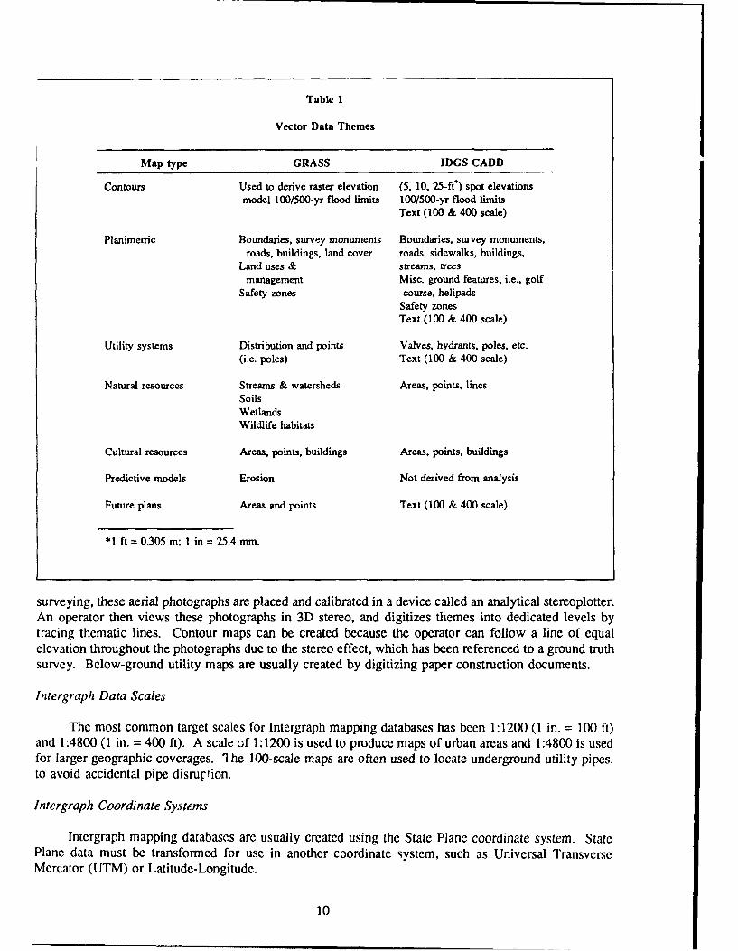
Table 1
Vector Data Themes
Map type GRASS IDGS CADD
Contours Used to derive raster elevation (5, 10, 25-ft) spot elevationsmodel 100/500-yr flood limits 100/500-yr flood limits
Text (100 & 400 scale)
Planimetric Boundaries, survey monuments Boundaries, survey monuments,roads, buildings, land cover roads, sidewalks, buildings,
Land uses & streams, treesmanagement Misc. ground features, i.e., golf
Safety zones course, helipadsSafety zonesText (100 & 400 scale)
Utility systems Distribution and points Valves, hydrants, poles, etc.(i.e. poles) Text (100 & 400 scale)
Natural resources Streams & watersheds Areas, points, linesSoilsWetlandsWildlife habitats
Cultural resources Areas, points, buildings Areas, points, buildings
Predictive models Erosion Not derived from analysis
Future plans Areas and points Text (100 & 400 scale)
*1 ft = 0.305 m; 1 in 25.4 mm.
surveying, these aerial photographs are placed and calibrated in a device called an analytical stereoplotter.An operator then views these photographs in 3D stereo, and digitizes themes into dedicated levels bytracing thematic lines. Contour maps can be created because the operator can follow a line of equalelevation throughout the photographs due to the stereo effect, which has been referenced to a ground truthsurvey. Below-ground utility maps are usually created by digitizing paper construction documents.
Intergraph Data Scales
The most common target scales for Intergraph mapping databases has been 1:1200 (1 in. = 100 ft)and 1:4800 (1 in. = 400 ft). A scale of 1:1200 is used to produce maps of urban areas and 1:4800 is usedfor larger geographic coverages. 'he 100-scale maps are often used to locate underground utility pipes,to avoid accidental pipe disruption.
Intergraph Coordinate Systems
Intergraph mapping databases are usually created using the State Plane coordinate system. StatePlane data must be transformed for use in another coordinate system, such as Universal TransverseMercator (UTM) or Latitude-Longitude.
10

Intergraph Vector File Structure
The Intergraph vector file structure addressed by this report is the IGDS. This is the most commonvector format used by Intergraph (Table 2). IGDS files contain 63 levels on which data can be digitizedand stored. This file structure aids graphic organization while digitizing complex maps and designs. Theuser may place different graphic clemncrts and themes on various levels. For example, roads may beplaced on one level within an IGDS file, road center lines on another level, sidewalks on a third level, andtext on a fourth level. Intergraph IGDS files are called "design files" and have the extension ".DGN".The internal file structure of IGDS files is licensed by Intergraph Corp.
Intergraph File Organization
Intergraph mapping databases are commonly divided into a grid pattern of sections called "facets,"which geographically delineate the contents and the size of a database map file. This is done to controlthe sheer volume of mapped detail inherent in facility-oriented mapping efforts. An entire militaryinstallation is comprised of many facets that must be attached to view the entire area. An examplefacetization scheme for the Chanute Air Force Base database is shown in Figure 1. The C2 facet wouldhave at least three associated individual files with dedicated levels reserved for planimetric, utility, andcontour information. If the planimetric, utility, and contour files for the C2 facet were merged, each datatheme in the resultant file should have its own dedicated level.
There are usually two sizes of facets corresponding to two target hardcopy map scales. Installationcantonment areas are usually mapped at a scale of 1:1200 and the whole installation is usually ma-pedat 1:4800. The facets for the 1:1200 scale data are generally 2500 ft north-south by 3000 ft east-west.Facets for the 1:4800 scale data are generally 10,000 ft north-south by 12,000 ft east-west.
Attributes may be associaled with the graphic elements in an Intergraph IGDS file. If attributes arepresent, they are stored in a separate attribute database. The attribute database for VAX-based IGDSsoftware is called Data Management and Retrieval System (DMRS). The attribute databases for IntergraphMicrostation based products are the relational database management systems Informix, Oracle, or Ingres.
Table 2
The Intergraph Vector Format
Software Vector Format
VAX-based softwue IGDS
Workstation-based Microstation 32 IGDS
PC-based Microstation IGDS
Workstation -based Microstation GIS IGDS
I1

IL I I(I
l
'131
t u1
12 ~t

The Grass GIS Database
Thematic Map Types
Typical GIS map types are of roads, hydrography, soils, geology, landcover, elevation, slope, aspect,land use, watersheds, wetlands, wildlife habitats, satellite imagery, and almost any type of map useful forenvironmental, economic, or land resource monitoring (Table 1). The diversity of small-scaleenvironmentally related maps is usually greater in a GIS than in a CADD system. The GRASS GIScontains both a vector file (dig) for a map and a raster file (cell). Associated with each vector file is avector attribute file (dig at), a vector topology file (digplus), and a vector category file (digcats).'Associated with each raster file is a header file (cellhd), a histogram range file (cellmisc), a category file(cats), a raster color file (colr), and a history file (hist). For GRASS release 4.0, vector files art, -- d fordisplay and reference; raster files are used for display, reference, and map analysis. All GRASS orfiles can be converted to GRASS raster files using the GRASS program v.to.rast.2
Although this report deals only with vector to vector translation, at this point it is instructive toexplain the difference between the vector and raster graphic data formats. The vector format describesgraphic positions by storing the x,y coordinate pairs that define a line or arc. Collections of coordinatepairs make up a line segment or arc segment, and segments eventually make up linear or polygonalfeatures. The raster format describes graphic position by assigning integer values to the individual gridcells of a two-dimensional matrix overlaid on the study area. If the data theme is a linear feature, suchas roads, and there is only one category of road (single lane, paved), then the grid cells are assigned avalue of either I for the presence of the road or zero for the absence of the road. Examples of morecomplex maps in raster format are soils maps and satellite images.
GRASS Data Sources
GIS maps are obtained from a wide array of sources. The selection of map source depends on mapavailability, project application scale, and application focus. If the application requires large scaleelevation data, sources supplying large scale data will be sought. 3 If large scale elevation data does notalready exist, it may have to be created using existing aerial photographs, or by scheduling an air photomission.
If the best vector linear or vector areal data can be acquired by digitizing mylar map separates,or by having maps scanned electromechanically, this approach is often taken.4 If data already exists inCADD vector format, data translation may be the most cost effective option.
GRASS Data Scales
The most common map scale used by GRASS is 1:24000. Many digital map layers in a GIS arethe result of digitizing 1:24000 U.S. Geological Survey (USGS) quadrangles. Other scales used dependon the focus of the project or the application. GRASS can use global data with a scale as small as 1 to5 degrees as well as maps having a scale as large as 1:1200 or larger. Scale is not necessarily limited.
Michael Shlapiro, et al., GRASS 3.0 Programmer's Manual, Automatic Data Processing (ADP) Report N-89/14 (U.S. ArmyConstruction Engineering Research Laboratory [USACERL], September 1989).
- James Westervelt, et al., GRASS Riferenwe Manual, N-87/22 (USACERL, September 1988).Stuart Bradshaw and Par Thompson. Optionfor Acquiring Elevation Data. Technical Manuscript (TM) N-89/20/ADA2200934(USACERL, January 1989).
a Jean Messersmith, "Map Preparation." in James Westervelt, et al., GRASS Reference Manual.
13

However, the 1:24000 scale is used most often because it best represents features on the ground at a scale
that covers an intermediate to large geographic area.
GRASS Coordinate Systems
The coordinate systems used by GRASS include the UTM, State Plane, Latitude/Longitude, andCartesian Coordinate system.
GRASS Vector File Structure
There are six GRASS vector files: the binary vector file (dig), the optional American StandardCode for Information Interchange (ASCII) vector file (dig ascii -this can be created from the binaryvector file using the GRASS program v.out.ascii) the topology file (digplus), the attribute file (dig att),the optional category file (dig_cats), and the reg file, which contains digitizing registration points.
The dig and dig ascii files are flat files (no levels) containing header information, nonintersect-ing curves called arcs, intersection points called nodes, and corresponding x,y coordinate pairs. Arcs canbe designated as lines (linear features) or areas (polygonal features). Each line or area is assigned a singleinteger attribute value called a category number, which is stored in the dig att file.
GRASS File Organization
GRASS vector maps are usually digitized as one file or map, covering the entire geographic areaof interest. If vector data must be digitized in segments, it is patched together after digitizing, or digitizedinto one UNIX vector file. GRASS vector attributes are stored in an associated vector attribute filedig_att.
It should be noted that Intergraph map databases are partitioned (facetized) to facilitate theproduction of 100- and 400-scale paper maps specified in typical mapping scopes of work for militaryinstallations. The decision to partition has nothing to do with any limitation of the Intergraph CADDsoftware. Complete coverage can be acquired for the entire geographic area of interest.
5 For a thorough description of the GRASS vector file structure, refer to the GRASS 4.0 Programmers Manual. Chapter 6.
14

3 THE HARDWARE ENVIRONMENT
GRASS development has been accomplished on a variety of UNIX-based machines to enhancesoftware portability. At the time of this writing, GRASS is officially supported on the followingplatforms:
6
* Masscomp mc6300* Sun Sparcstation 1, Sun Sparcstation 2, Sparcstation IPC* Sun 386i* AT&T 6386* AT&T 3b2* PC 386 (Compaq and Dell)* Silicon Graphics IRIS 4D/20* Apple Mac 11* Tektronix XD88* NCR 3345• Intergraph Interpro Series models 240, 2020, 3050, 6000, 6040* IBM System 6000/Model 320 Configuration• Data General Avion 300c.
Users may want to perform translation on various hardware configurations. This chapter offers agcneric example of a hardware environment made up of a mixture of Intergraph, PC, and GRASSworkstation platforms, illustrated in Figure 2.
Inm T cro240
I Sur,386 TR- repeaterbox
ETHERNET BACKBONE
Figure 2. Schematic of a Mixed Hardware Environment.
More specific configuration details may be found in: Douglas Brooks, Michael Shapiro, and Mark Johnson, GRASS HardwareConfiguraiion Guide. ADP N-89/21/ADA220954 (USACERL, March 1989).
15

All Sun workstations use the Sun 4.1 operating system, which is characteristic of the Berkley versionof UNIX. All other workstations (listed above) use operating systems more characteristic of AT&TSystem V UNIX. Interpro workstations use a System V version called CLIX. The VAX 11/785 andmicrovax hosts use the VMS operating system. The PC 386 workstations use System V UNIX operatingsystem called Dell UNIX or Interactive, with Etherlink cards connecting to the ethernet. PC hard diskscommonly can be partitioned with both DOS and Unix partitions (i.e., a 400 Mb UNIX and 100 Mb DOSpartition, allowing the DOS-based microstation to still be operated). PC 386 configurations often haveadditional software packaged with the operating system to move data between the DOS and UNIXpartitions, allowing data generated in the DOS partition to be transferred out to the network.
With the exception of the VAX machines, all other workstations run Network File System (NFS)software, which comes with the purchase of the Sun Operating System. The Sun 4/280 functions as a fileserver. NFS software from Intergraph is used to connect intergraph workstations to the rest of the existingGRASS workstations.
IGDS data is binary compatible between the VAXs, Interpros, and PC-based IGDS products. Datahas been successfully downloaded from magnetic tape to the VAX 11/785, transferred across the networkand from UNIX to the DOS partition to be edited in Microstation PC. However, some data compatibilityproblems have been encountered in transferring GRASS binary vector data between the Sun and Interproenvironments. This may be due to byte-swapping differences between the Sun and Interpro machines.In these cases, data is simply transferred in ASCII format to the target workstation, where it is thenconverted to binary form.
16

4 ASPECTS OF IGDS MAPPING DATABASES THAT AFFECT TRANSLATION
Digital Integrity
Often, attention has not been paid to the delivery of a digitally "clean" database product suitablefor translation into a topologic GIS format. Emphasis has been placed on the production of a paperproduct with traditional paper-based graphics standards. Therefore, digital files contain many overshoots,undershoots, and discontinuous and duplicate lines.
For instance, contour files have discontinuous contour lines, which require extensive editing and"best guesses" to connect into continuous form. Editing may be so extensive as to prohibit conversionof the data. Contour interval text labels are inserted in the breaks of the discontinuous contour lines.Many discowinuous lines exist where sharp changes in topographic relief would result in close, tightlyfitted contour line representations. Depressions are represented with special graphics symbols that mustbe edited. Again, this results from an emphasis on a paper map product.
Global Origin and Coordinate Representation
The global origin and coordinate representation should be set up so that the associated coordinatesof all ground features depicted in the database identify the actual State Plane coordinate position offeatures. Some databases have been delivered with data elements that do not match actual groundcoordinates, or with coordinates in a truncated, abbreviated form.
Design File Organization
Files must be delivered complete and in clear order, with proper facetization. The database requiresa consistent facetization scheme or complete geographic thematic coverage. Data themes must be locatedon correct levels, with consistent feature color coding, linestyles, and lineweights. Data themes (e.g.,sidewalks, roads, fences) must be kept consistently on their designated levels. Facets should cover allimportant geographical features, such as installation boundaries.
Database Documentation
Databases should be delivered in a consistent and organized manner, delivery of a 9-track tape andfile listings of contents is insufficient. Databases should be delivered with a documentation report, ifpossible. Names of database files should indicate contents. File types should be separated and data sourceor scale technical details should be included. Refer to Chapter 15 (p 44) for documentation guidelineson the creation of multi-use data.
Visibility of Data Elements Depicting Map Features
Some data elements, such as Complex Patterning, are only visible when specific display switchesare set. Enable the patlern display and observe the graphics display to evaluate existing data which mightnot he visible when pattern display is off.
17

Graphics Standards
The graphic symbolism of some features (such as topographic depressions) will have no graphiccounterpart in GRASS, where topography is described via an elevation model. Such features must beedited, either in the CADD system or GIS. Care must be taken if it is desirable to translate MicrostationCADD symbols called "cells" (telephone poles, transformers, etc.). Cells may have to be decomposed intoindividual graphic elements before translation. The dxf import program distributed with GRASS will onlyrecognize points, lines, polylines and text; other types of data are ignored. Decomposing cells using theMicrostation DROP COMPLEX STATUS COMMAND will increase file size and require editing labor.A cell symbol, such as a telephone pole may become decomposed into a circle filled with many individualline segments. Cell symbols may be exchanged globally for simpler representations which do not requireediting. To do this, refer to the CELL REPLACER UTILITY (rcl.exe) which comes bundled withMicrostation.
Attached Reference Files and File Compression
Attachment of too many reference files can obscure actual file contents and require labor to detach.Files are often not compressed, ballooning the size of the database and slowing network transmission.However, IGDS data compression sometimes results in file corruption. It is advisable to lback up" beforecompressing IGDS files.
Data Redundancy and File Size
Titleblocks and legends are often found in every file. Database files with 100- and 400-scalecontain duplicate information. Often duplicate data elements (i.e., contour lines) are found and copied inan overlapping fashion at the same coordinate location. Contour file sizes are very large, even on a per-facet basis. Record increment digitizing thresholds may be set to capture more data points than necessaryto describe topography. Under these conditions, merging all contour facets together will create a verylarge and unwieldy file for transport over a network and conversion to raster DEM format.
18
5 UNDERSTANDING THE IGDS MAPPING DATABASE
Before IGDS files are translated into GRASS, it is first necessary to assess the quality of the graphicdata and identify the presence of factors that will affect translation. To make an assessment and preparethe data, there is no alternative to learning the Intergraph CADD system. The documentation, whichshould accompany the database (Chapter 16, "Documentation Needed for IGDS Data Translations," p 49-50), serves as a general guide to conditions that should be found in the database. The individualperforming the translation must check the database by sampling the files to verify consistent compliancewith the documentation and to note anomalies. Digitizing errors and exceptions to documentedinformation may exist. Targeting a data theme that is not overly complex is a good way to begin theprocess and learn translation pitfalls. It also will be necessary to gather information needed to run thetranslation programs. Chapters 7 to 11 (pp 25-39) list and describe the translation programs. An analysisof IGDS data will determine the condition of the database and the labor involved in performingconversion. This will help determine the translation program and path to use when choosing between thedlg and dxf alternatives described in this report.
IGDS Hardware Environments
There are three Intergraph hardware environments for an individual performing translation to display,query, and edit IGDS data: the VMS VAX IGDS environment; the UNIX computer workstationenvironment using Microstation 32 software; and the DOS PC environment using Intergraph Microstationsoftware. These three systems offer similar display and query capabilities, but the commands andprocedures differ slightly from system to system. This section, describes the query procedures in genericIntergraph terms instead of specifying step-by-step commands.
Some IGDS Analysis and Editing Tools
IGDS Graphics Display Environment
Within the IGDS graphics display environment, the user may control data visibility by turning onand off design file levels to determine what thematic components are on each level. This is the mostappropriate method for initial evaluation of data. Selection of one of the element manipulation commands,such as the change color command, can also be used to echo the design file level of a particular graphicclement to the screen. After selecting the clement manipulation command and identifying the graphicclement with the cursor, the data level will be displayed. Choose the reject option to abort the programso an clement manipulation will not actually occur.
The supplement library can also be accessed to display tabular information about a particular graphicon a virtual screen. A command that displays this information in the VAX environment is:uc=pro dd sup:anl.7 This command displays the data level, element type, line style, line color, andother useful information.
Intergraph Aicrostation Referewc (;uide, DSA0271 10 (Intergraph Corp., 1989).
19

Edit Display Graphics
You may also analyze and edit data outside the graphics environment using the Edit DisplayGraphics (EDG) utility. EDG is the Intergraph Edit Graphics Utility (refer to EDG User's Guide,DSYS103 (1987), and Microstation Reference Guide). EDG is an extremely useful, powerful programthat allows one to edit graphics outside the display environment. EDG should be used with caution sincecommands can globally alter data. (Be sure to make backups.) EDG offers an automation alternative fortarget data found to be in excellent condition (via evaluation by graphics display). In addition to itsfunction as an editing tool, EDG can supply the user with ASCII (tabular) information about design files,which can be stored in a readable file and printed for later use. Among EDG's querying options is onethat provides general information about a design file, including a list of element types, data levels, lineweights, line styles, line colors, fonts, number of active elements, number of deleted elements, and thetotal number of elements. The level location of the design file header, as well as whether the file is 2Dor 3D, is also included.
A full listing of all of the elements in a design file can be requested; however, be aware thatprintouts of this type of information for normal to large-scale files may be long (more than 100 pages).A specific list of element symbology for one or more element types, or a list of the elements and thesymbology for a particular level can also be requested. EDG procedures and options vary with the IGDSsoftware and hardware environment.
Organization and Preliminary Data Analysis
After thoroughly evaluating the documentation accompanying the database, copy the data fromthe storage medium to the computer's disk using standard input, and organize the data files according tofiletype: planimetric, contour, or utility. Make sure that all database files for the coverage are present.It is a vitally important requirement throughout the translation process to maintain a high degree oforganization and detailed bookeeping. Begin an analysis of a simple target data theme of interest, suchas boundaries. Methodically sample each file, making sure it will load, while checking the followingimportant characteristics.
Data Levels, Element Type, and Symhology
Intergraph IGDS design files contain 63 levels on which data may be digitized. All 63 levels areavailable in each IGDS file regardless of whether they are empty or contain data. IGDS levels maycontain nondisplayable header data, graphic data, or displayable text. There are many graphic elementtypes used to construct the graphics that describe map themes, e.g., "line," "linestring," "curve,""connected string," "ellipse," etc. (refer to EDG User's Guide, DSYS103). Element symbology refersto linestyle (dashed, solid, etc.) linecolor, and lineweight (narrow or wide).
The thematic category of graphic data that resides on each level is important. For example, thematiccategories representing a road map might be primary roads, secondary roads, and tertiary roads. Thethematic categories of graphic elements representing topography might be index contours, intermediatecontours, and spot elevations. Index contours might reside on level 50, intermediate contours on level 51,spot elevations on level 52, and contour text labels on level 55.
To run the two IGDS-to-GRASS translation programs described in this report, knowledge of whichdesign file levels contain graphic data and textual data is required. (Refer to your database documenta-tion.) However, you must check to verify that the theme of interest is consistently on the correct level.At the same time you can zoom in on areas to evaluate the condition of the graphics (i.e., overlaps,
20

undershoots, etc.). Also check to verify that there are no reference file attachments to confuse your visualanalyses. In addition, you should set the display visibility switches to show complex patterns that mayhave been used to represent railroads or an installation border. The color of graphic elements may changedepending on the graphic display capabilities of your platform. Data may display with the color, black,which will not be visible. There may be duplicate lines that must be removed before translation.
Global Origin
The global origin is set up prior to the digitizing process and must be retained to reflect the data'scoordinate system. For example, the global origin for the Fort Sill database is go=-1700000,-300000.These negative values indicate that the graphic elements in the database will not be truly georeferencedin the State Plane coordinate system, and that the global origin must be moved. When this global originis correct in the design file display environment, the coordinate values of graphic elements, when queried,will echo the correct ground coordinates to the screen (in this case, State Plane). To check the globalorigin within the display environment, in either VAX-IGDS, Microstation 32, or PC Microstation, type:go=$. If the global origin has not been changed, the correct global origin will be displayed. Thedigitizing contractor can provide the correct global origin in which the data were digitized. This valueshould be retained in the seed file used to construct the database.
Coordinate System
It is important to check the coordinates of the design file in the IGDS display environment toconfirm that they are accurate (i.e., State Plane, UTM, etc.). After checking the global origin, thecoordinates can be queried by selecting the key point snaplock option in VAX-IGDS, Microstation 32, orPC Microstation, and then using the tentative point (T) button on the nine-button cursor. When the cross-hair pointer snaps to the nearest graphic point, the coordinates of that point will be displayed on thescreen. If the correct coordinates are not displayed, the global origin may not be set to the correct x,yvalues. You can correct the misrcgistration of a file's coordinate system if you know the true groundposition of an element in the database (preferably a survey comment). Input this coordinate to theGLOBAL ORIGIN command and tag the crosshair target on the known monument to re-register thecoordinate syste. Diagrams of survey monuments with corresponding state plane coordinates are generallyavailable from Engineering Divisions at installations. However, one should be cautious, as sometimesinstallations will devise their own unique coordinate system.
File Size
Note that the IGDS file sizes may be deceiving. IGDS files retain marked deleted graphic elements.Only when a file is compressed are these deleted elements actually removed from the file. Files need notbe compressed, unless file sizes are unwieldy. IGDS data compression sometimes yield file corruptions;backups are required. EDG repairs on these file corruptions are varied in complexity. File size is animportant factor in data translation because some translation programs temporarily increase file size(dAf,,ut).
21

6 TARGETING AND EDITING IGDS DATA
Targeting Data
It is necessary to evaluate the source of any data to justify conversion. Some data themes may havebeen digitized from out-of-date paper sources. Data themes should be prioritized for conversion. It maybe useful to refer to existing map products produced from the database to prioritize data themes. Notethat, at the time of this writing, the program to convert contour line data to elevation model raster format(r.surf.contour) is computationally intensive. Preliminary results from r.suf.idw2 have greatly reducedprocessing time. It is best to evaluate the contour data conversion path and results before doing extensiveediting.
Editing IGDS Data
Following the analysis of IGDS data, some aspects of the design file may need to be edited(changed) to facilitate translation into GRASS (refer to Chapter 4, "Aspects of IGDS Mapping Databasesthat Affect Translation," p 17). Before editing a file, it is a good idea to make a binary copy in casemistakes are made. IGDS target data for conversion should be stripped and isolated out of the originalfile into a new (smaller) file containing only the data level(s) of interest. This can be done by using EDGor graphically, by controlling level visibility, and Fence Filing the data level(s). After level stripping, besure to note the resultant file size of the target data using the appropriate command of the supportingoperating system: DOS, VMS, or UNIX. In the level-stripping procedure, no internally deleted graphicelements are transferred to the new file; in effect, this performs an automatic compress. File size willdetermine whether files must be translated individually (facet by facet), or whether files can be mergedprior to translation. Merging facets creates larger files, but can simplify the conversion from IGDS to dig,which might otherwise take 10 or 20 individual conversions and patches, sometimes to a single step. Onemust always consider when to make file backups. You must balance data being worked on so as not tobottleneck the translation process by not having enough storage for processing. It is best to backup dataat important stages of the preparation and conversion process. When to backup is usually determined byevaluating how much work has been invested in specific file(s). Other possible manipulations and graphicchanges to IGDS data before translation into GRASS are:
1. Search for missing data from a level by turning levels on and off and perhaps displayingadjacent files as references. Use display controls to magnify data, to pan over data, or to create multipleviewports.
2. Change the color of data or symbology to enhance understanding. Change the elementsymbology of a group of graphics on a design file level to give the graphics a separate feature code whenrunning DLGOUT. DLGOUT uses element symbology to distinguish graphics when assigning graphicsa feature code (FC=category). Refer to Chapter 9, "How to Run Intergraph VAX DLGOUT" (p 29).DLGOUT changes all IODS styles to the solid style during translation.
3. Move data to a different level in either the graphics display environment or EDG.
4. Move data on a level(s) to a new file using either the graphics display environment or EDG.This allows the user to translate a file containing only one or two levels without having to translate thedata on the unwanted levels. The levels are separated out of the dxf file when it is imported into GRASSduring the GRASS import program v.in.dxf. The program v.in.dxf creates a GRASS vector file for each
22

level in the dxf file. At this point, unwanted vector files can be removed, but translating unwanted levels
results in many dxf files that take up storage and may be unnecessary.
5. Change an element type (e.g., complex to primary) curve string to a line string, cell toindividual elements.
6. Delete data, such as duplicate linework, or graphics standards for topologic integrity. Joinbroken lines, trim line overshoots, or correct crossing contour lines.
7. Change display visibility parameters to show patterned elements, such as railroads or perhapsinstallation borders.
8. Detach reference files. It may be useful to attach reference files for analysis and editing.
9. Compress a file.
10. Change the global origin to move data to correct coordinate location.
11. Strip out data from one level to a new level or file using EDG to differentiate data by color,linestyle, lineweight, symbology, or element type. If two types of data reside on the same level, such asroads and streams, you may want to move the streams to a separate level, or to a separate design file.Both of these solutions will enable the two thematic types to be translated into two separate GRASS vectorfiles. Refer to Chapter 20, "Exporting DLG and DXF Files From GRASS" (p 51)
12. Repair a corrupt file using EDG.
13. Merge two (or more) files; split a file into two (or more) pieces.
14. Change the color of a group of graphics to distinguish the group from another group ofgraphics on the same design file level. This would be applicable only if DLGOUT was to be run on thedata after editing. DLGOUT is the Intergraph program that translates IGDS files to USGS Digital LineGraph (DLG) files with the option to assign the line color, line weight, or line style on an IGDS level toa DLG feature code (FC=category). Refer to "When To Use Intergraph DLGOU7" (p 26) and "How ToRun Intcrgraph VAX DLGOUT" (p 29).
All of these changes can be made within the IGDS display environment. Graphic editing may alsobe accomplished using (see Edit Display Graphics (p 20). Editing in the display environment rather thanEDG, however, is safer for new users since major mistakes are easier to make using EDG. EDG is anexcellent tool to locate and identify data and data levels.
Editing GRASS Data
Sometimes data must be edited after translation from IGDS to GRASS. Some examples are:
1. The joining of discontinuous contour lines that were broken to place elevation text labels.L.ocating the text spaces in contours is useful after translation to help identify where the text label boxesfor the contours, created by the GRASS import program v.in.dxf, should be when the box vector file isoverlaid in the GRASS program digit. Occasionally there may be text (boxes) in a contour IGDS fileidentifying features other than the index contours. These text boxes are needed to check for mislabeled
23
contours within GRASS digit (refer to "v.cadlabel" (p 421 for further explanation regarding the creationof boxes around IGDS text data).
2. Screen digitizing of small line breaks is made easier in the GRASS digit program because thebreaks are automatically highlighted with colored nodes. However, this advantage must be weighedagainst program performance with large volumes of data. Microstation handles large volumes of datamore quickly during in-house tests. In addition, Microstation has powerful panning and multiple viewportdisplay capabilities. Both programs have adjustable snapping thresholds; however, the Microstationprogram has an undo feature that tolerates erasure mistakes, whereas the digit program does not.
Automation Possibilities
Automation of the IGDS editing process is helped by a well-organized database that strictly adheresto the level structuring of data themes. If the level structuring of data themes varies from file to file (facetto faceL), then individual modifications must be repeated for many or all of the facets (IGDS files) in thedatabase. For example, a modification might be necessary when moving levels 50 and 55 for all files inthe database to a single new file prior to translation. Automation will not be successful if many of thefiles have level 50 data themes on the wrong level. Automation can decrease translation time, file size,and aid in troubleshooting translation problems. When facets are translated separately, for example,primary roads on level 50 and secondary roads on level 55, the level stripping process would have to berepeated for each facet. Automation or bulk editing allows the user to run the editing sequence once and,in this case, strip levels 50 and 55 from any number of files without operator attention. This kind ofautomation is accomplished using editing software that runs outside the Intergraph graphics interface. TheEdit Graphics Utility (refer to "Editing IGDS Data," p 23) provides this capability. A program calledProgrammable EDG is available to automate the editing of files.8
Check Plots
Hardcopy paper plots may be useful as references for targeting and editing IGDS data forconversion. These can be produced from the IGDS database if one has access to a pen plotter. Anotherapproach would be to obtain blueprints of the map products derived from the IGDS mapping database.It can be difficult to maintain a perspective when one is zooming in and out of a complex file that takesseveral minutes to replot on the graphics screen. Referring to a check plot can be a useful "road map"to help you keep focused on the data of interest and to keep tabs on where you are in the editing process.After conversion to GRASS, another vector plot may be created to verify an accurate translation.
X Programmable FDG is distributed hy Axiom Software, P.O. Box 210655, San Francisco, CA 94121-0655. tel. 415/751-8404.
24

7 INTERGRAPH TO GRASS VECTOR TRANSLATION PATHS
There are presently two possible vector translation pathr from Intergraph's IGDS vector format tothe GRASS vector dig format. One path uses the USGS DLG format as an intermediary format, and theother path uses the CAD DXF format as an intermediary format. The DXF or DLG file is then importedinto GRASS using GRASS capabilities. Figure 3 shows the two translation paths.
IGDS ------------ > DLG ---------------- > GRASS vect(DLGO UT) (v.import)
IGDS ------------ > DXF ---------------- > GRASS vect(drfout) (v.in.dx")
Figure 3. Intergraph-to-GRASS Vector Translation Paths.
The current GRASS vector import capabilities are:
1. DLG-3 Optional Format2. DXF3. TID (experimental DMA data)4. ADRG (experimental DMA data).
The software programs that were evaluated are the two Intergraph IGDS export programs DLGOUTand dxfout and the two GRASS import programs v.import and v.in.dxf. DLGOUT runs on the IntergraphVAX platform only, and dxfout is an Intergraph Microstation 32 and PC Microstation-based product. Theprogram dxfout is distributed with and comes packaged in the Microstation software. The two GRASSimport programs, v.inport and v.in.dxf, are executed within GRASS, and therefore run on all of theGRASS hardware platforms, such as the Masscomp, Sun, and Intergraph Interpro workstations. 9
See the GRASS Hardware Configuration Guide.
25

8 CHOOSING DLG OR DXF AS AN INTERMEDIARY VECTOR FORMAT
Both translation paths have produced successful results. The discussion that follows assumes youhave the two alternative translation paths at your disposal. The additional cost of purchasing DLGOUTmay not be warranted, especially when dxfout comes packaged with Microstation 32 and Microstation PC.DLGOUT offers advantages to databases prepared with its use in mind, i.e., when the data is clean andthe DLGOUT feature coding capabilities can be used. However, most of the mapping databases we haveevaluated have been produced with a paper map product in mind, not with DLGOUT. dxfoua is easy torun and simplifies the complexity of translating different IGDS element types into lines and polylines. Atranslation parameter file exists that may be used to screen cell symbols, to eliminate them from thetranslation process. File size and contour labeling issues can also be considered when choosing betweenmethods. These factors and the basic differences between DLGOUT and dxfout, as well as some importantaspects of v.in.df that relate to translation decisions, will be covered in this chapter.
When To Use Intergraph DLGOUT
DLGOUT is the Intergraph program that converts Intergraph IGDS vector format to USGS DigitalLine Graph format. 10 The difference between this program and the Intergraph dxfout translator is thatelement symbology in the IGDS file can be assigned a DLG major and minor feature code in DLGOUT,and then when the DLG file is converted to dip, the dig file will have category labels. Each category labelin the dig file will have the same label .:umber as the label number (feature code) assigned to thelineweight, linestyle, or linecolor in the IGDS file during DLGOUT. All IGDS linestyles (dashed and,oited lines, etc.) will become solid lines in DLG for -.... ;. d thercfore in GRASS dig format.
Another adv;ntage of DLGOUT s mat it does not increase the intermediate vector file size quiteas much as dxfout, although both translators may increase the file size (Table 3). The final GRASS digfile may be smaller or larger thai. the IGP file, hut is usually significantly smaller than the intermediatevector file.
There are two Intergraph versions of DLGOUT. One resides on the VAX and the other is packagedin Microstation GIS Translator (MGT), which is a modular part of Microstation GIS. The VAX version,at the time of this printing, is not able to retain the elevation values internally tagged to the IGDS contourlines, if the contour lines were digitized as Intergraph curve elements. During DLGOUT, the prograrr."strokes" curve elements, converting thc-i to 'ntergraph line elements, and in the process does not savethe tagged elevation values. Null elevation values are put in their place. When DLGOUT encounters anull value, it quits. A logical solution to this problem would be to run the Intergraph curve-to-lineconversion program" that changes curve elements to line elements before running DLGOUT; however,this program also strokes the curves in the process of converting them to lines, and replaces the elevationvalues with null values. If the data theme of the IGDS file to be translated into GRASS vector formatis elevation cortours, it is advised to use the DLGOUT version that runs on Microstation 32, or dxfout.If some of the contour lines in an IGDS file are tagged with elevation values and some are tagged w;thnull values, DLGOUT will not run. If all of the contours are tagged, or if the contours are not tagged atall (with elevation values or with null values), DLGOUT will run successfully. The advantage of usingDLGOUT is that, if labels or contour elevation labels are able to be translated, little or no labeling willhave to be done in GRASS v.digit after translation.
Intergraph DLG(OUT User's (;uide, I)MAPI45 (intCrgraph Corp., 1986).See th Inergraph Spatial Editor Users Guide.
26

Table 3
Target and Intermediate File sizes in Bytes
ASCII ASCII BinaryIGDS DXF DLG DIG DIG CELL
393,216 2,174.036 1.536,894 943,951 564,907 2,000,000124,928 274,262 83,430 30,379 52,127
2,564,096 21,668,253 41,416,011
Intergraph dxfout
dxfout is the Intergraph translator that converts IGDS vector data to DXF format. It runs in theIntergraph Microstation environment in either Microstation 32 or PC Microstation. It is useful fortranslating all thematic types of IGDS data (roads, streams, contours, flood plains, etc.). One importantaspect of using dxfout is that, if IGDS contours (usually index contours) are labeled with graphic (visible)text, these can be translated into the DXF file (dxfout), imported into GRASS as a vector file (v.in.dxj),read using the GRASS program v.cadlabel, and assigned as category labels to the nearest index contour.All contours that have text labels, will then have GRASS category labels (elevations) after v.cadlabel andwill not have to be labeled in GRASS v.digit. The individual performing translation is again urged toevaluate the complete contour conversion path to DEM product before extensive editing, including the useof r.surf contour or r.surfidw2.
Based on the discussion above and in "How to Run Intergraph DLGOUT' (p 29), dxfout is bestused on elevation contour data that meet the following conditions:
1. The contour data do not have internally tagged elevation values.
2. The contour data, digitized as curve elements, do have internally tagged elevation values, butthe Microstation 32 version of DLGOUT (packaged in MGT) is not available.
3. MGT is available, but some of the contour lines in the elevation contour data are tagged withelevation (z) values and some are tagged with null values. (The user should check to see if the currentversion of DLGOUT in MGT will accept null z values.)
4. Only the index contours labeled with graphic (visual) text will be translated into GRASS.
5. The user prefers to use dxfout for its ease of execution, and does not mind labeling some(usually intermediate) contours after translation into GRASS. Labeling of all contour lines is required ifthe GRASS vector contour file is to be converted into a raster digital elevation model. You must labelat least the index contours if the GRASS vector contour data will be displayed as a vector contour file.
dxfout is easier to use than DLGOUT and can be followed by the user-friendly GRASS contour textlabel extraction program v.cadlabel and a GRASS bulk contour labeling capability in v.digit. It willtranslate the IGDS line style (dashed, dash dot, etc.) as a solid line. A dashed line in IGDS will becomea solid line in GRASS dig. To avoid problems, the individual performing translation must check graphicelements to verify whether lines are short and separate, or connected lines that are merely being displayed
27

as a line style or pattern. These conditions can be further controlled with a dxfout environmentalparameter file that is referenced during dxfout execution to define dxfout results.
To fully describe the capabilities of dxfout, it is necessary to describe the GRASS programs thatincrease the efficiency and ease of labeling files that have been translated using difout. (Refer to "Howto Run Intergraph dxfout," p 32, and "Summary of the IGDS-DXF-GRASS Translation Sequence," p 37.)
Chapter Summary
DLGOUT would be a preferred translation method when contour lines have been digitized withcontinuous lines (no text index label breaks) that have been attributed with elevation values or whenlinestyle symbology can be used to derive category values. However, these conditions are most often truewhen the data were created with the use of DLGOUT in mind. Few of the databases encountered so farhave these characteristics. Most map databases have been created with the focus of producing paper mapproducts, so that housekeeping on the digital database is often in need of attention. Table 4 summarizesthe material presented in this chapter.
Table 4
Advantages/Disadvantages or DLGOUT and dxfout
DLGOUT dxfout
Advantages Disadvantages Advantages Disadvantages
Assigns major and minor • Does not retain • Ease of use; free * Creates large int: rme-DLG feature code to tagged elevation with Mcrostation diate files.IGDS element values for curve ele- products.symbology. ments. . No translation utility
. Translation Table to convert z valueConverts IGDS line style - Will not run if tagged for controlling attributes of contourto solid line style. null z values exist in conversions, lines.
the fide.* Ignores text as default. * Simplifies com- * No utility to assign
Creates null z values plex data ele- attributes to graphic
* Usually creates files for z values of curve ments. symbology.smaller than DXF. elements.
. Translates text ifpresent.
• GRASS transla-tion utilities canconvert DXF textto GRASS labels.(Contour label-ling)
28

9 EXPORTING DLG AND DXF FILES FROM INTERGRAPH
How To Run Intergraph VAX DLGOUT
Two files are required to run VAX DLGOUT on an IGDS design file. Both files are created by theuser using a screen text editor and are stored in a flat ASCII file. The first file is a header file, given afilename with a prefix that matches the name of the design file, and the extension .hdr. For example, ifthe design file is named contours.dgn;1 the header file should be given the name contours.hdr. The VMSname will bccome contours.hdrl. This allows the DLGOUT program to find the header file withoutprompting the user for the filename.
The second file is a DLGOUT parameter file. It can be given any name by the user, for example,contours.param. The full name in VAX VMS will then become contours.param.;1. Underbars shouldnot be used in the filename because this may cause confusion in the VMS operating system. The userwill be prompted for the parameter filename when running DLGOUT, and should type the full VMSfilcname, including the semicolon followed by the version number.
DLGOUT also has the capability to translate IGDS attributes stored in the Intergraph VAX-basedDMRS. This option of DLGOUT was not evaluated in this study, however, and will not be included inthis report.
The Header File
An example of the DLGOUT header file is:
BAN= FT. SILL TRANSPORTATION - State Plane, Feet
The only required characters of the statement are "BAN=". Refer to the Intergraph DLGOUT User'sGuide for more information. This example header file is for a Fort Sill, Oklahoma transportation, orroads, design file. The user decided to include the coordinate system (state plane) and the units (feet).There is one space after the equals sign in the header file. The other special characters, the dash, comma,and period, are optional.
The Parameter File
An example DLGOUT parameter file is shown below:
OPT: SOVR: Contour Facet IMLT: 1000CAS: NetworkNOD: IREC: ID=AREA,ET=TEXT,LV=60,FC=000-000REC: ID=AREA,ET=TEXT,LV=60,CO=4REC: I D=LINE,ET=LINE,LV= 1 ,CO=6,FC=020-0001REC: ID=LINE,ET=LINE,LV=5,CO=3,FC=020-0002
There are one or two spaces after the colon in the parameter file, but there are no spaces on eitherside of the commas or the equals signs. The purpose of the parameter file is to identify the kinds of
29

elements (ID= line, area, or node) that are to be translated, what level they reside on (LV= level-number),and what DLG feature code they are to be assigned (FC= number).
The example parameter file is a contour design file of one facet of Fort Drum, GA. The minimumrequirements for a parameter file are: one OPT statement, one OVR statement, one MLT statement, oneCAS statement, one NOD statement, and at least three REC statements (one for the DLG inside area, onefor the DLG outside area, and at least one for the level of data being translated).
The argument following the keyword OPT is either an "S" or an "M". "S" indicates that only onecontour file is being described by the parameter file (singular mode), and "M" indicates more than onedesign file will be described in the parameter file (multiple mode). 12 This document will cover only thesingular mode. The line below the OPT statement is left empty.
The next entry is the OVR statement. This keyword is followed by a map name chosen by the user.The name cannot exceed 20 ASCII characters. In the Fort Drum example parameter file, the name is"Contour Facet I".
The MLT statement is typed next. The argument within this statement is a number that equals thedesign file Sub Units (SU) multiplied by the Positional Lnits (PU). The SU and PU for each IGDS designfile can be found by checking the Design Options menu. In the Fort Drum example, the SU is 10 andthe PU 100, so the MLT value is 1000. New versions of VAX DLGOUT (1989 and up) have no limiton the MLT value.
The CAS statement has two options, Network or Area. Network applies to linear data, and Areaapplies to data having many closed polygons. If this statement is omitted, the CAS defaults to Area.13
The NOD statement allows the user to direct the program to place nodes throughout the design fileif this was not done during digitizing. The NOD options are:
* 0 - Nodes are already presentI 1 - Place nodes throughout the design file
* 2 - Place nodes throughout the design file and tag them with identifications.
If this statement is omitted, the NOD defaults to "0".
The next entry is the first REC statement, which must be the REC statement for the inside area ofthe DLG file. The inside and outside areas are user-defined by drawing a box around the contour data,and by using the IGDS place block command in the IGDS graphic environment (ice). The box must bedrawn on level 60 of the design file. For the inside area, the ID= is always AREA. The inside area isidentified by placing an element type (ET=) text node inside the area after it is drawn using the IGDScommand place text node. The argument following ET= is therefore TEXT. The feature code (FC=), orcategory label for the DLG inside area, is always 000-0000. The first three zeros of this number are theDLG major code and the last four zeros are the DLG minor code. Refer to Digital Line Graphs from1:24000 Scale Maps, National Cartographic Information Center, Reston, VA. The entire first RECstatement will always appear as it does in the Fort Drum example.
;2 For further information refer to pages B-3 through B-5 in the nirergraph DLGOUT User's Guide.
Refer to Intergraph DLGOUrT User's Guide for further information.
30

The second REC statement always defines the outside area of the DLG file. This is user-defined byplacing a text node outside the box that was drawn around the data. To ensure that this text node isdistinguished from the first text node, it is best to give it a different color using the change color optionunder element manipulations in the IGDS graphics environment. The color is then indicated in the RECstatement by CO=colornumber. The outside area should not be given a DLG feature code (FC=).
The next REC statements identify design file levels that contain data to be translated. Each levelor each feature code per level must be identified using a separate REC statement. Feature codes on thesame level or on separate levels, can be distinguished by linestyle (ST=), lineweight (WT=), and linecolor(CO=). Refer to the Intergraph DLGOUT User's Guide for other REC statement keywords.
Only the minor feature code will be translated by the GRASS v.import program, which imports DLGdata into GRASS. After importing the DLG data, the GRASS vector lines will have GRASS categorylabels corresponding to the DLG minor feature code. The labels will be displayable in v.digit afterimporting the data. For example, if the DLG feature code (FC=) is 020-0003, the GRASS vector categorylabel will be 3.
The number of feature codes in an IGDS design file that can be distinguished using IGDS levels,line styles, line colors, and line weights are limited to the number of design file levels, and the IGDS linesymbology. There are seven line styles, seven line colors, seven line weights, and 63 design file levels(of which 62 are available). The maximum number of feature codes that can be converted from IGDSto DLG using the VAX DLGOUT translator is (7x3)x62 or approximately 1302 feature codes.
In the Fort Drum example contour file, there are two design file levels that contain data to betranslated (although other levels may contain data of no interest). The index contours, with a contourinterval of 25 ft and the line color yellow (CO=6), reside on level 1. They are digitized as lines (versusareas or nodes) and are therefore identified as ID=LINE. If the contour lines are digitized as Intergraphcurve elements, they are still assigned the identification ID=LINE in the parameter file. The options forID= are only LINE, AREA, and NODE. The intermediate contours, with a contour interval of 5 ft andthe line color of red, reside on level 5. This parameter file would translate only lines of color 6 on level1, and assign them the GRASS category number 1. It would also translate only lines of color 3 on level5, and assign them GRASS category number 2. It will not translate the box on level 60.
Graphic Preparation
As mentioned in "The Parameter File" (p 29), a box and two text nodes must be placed on level60 in the IGDS design file. Four text strings must also be placed by the user on level 60. One text stringshould be placed at each of the four comers of the box defining the DLG universe. The text strings donot have to be located at exactly the box comers, but can be placed anywhere approximately near thecomer and outside of the box. Each text string should contain the latitude and longitude of the border ofthe whole map area. For example, the approximate latitude and longitude boundaries of the entire FortDrum installation may be placed around each translated IGDS facet of Fort Drum. The latitude andlongitude, then, do not correspond to the four comers of each design file, but to the whole geographicarea. These coordinates are read by the DGLOUT translator and placed in the DLG header. The textstrings should be typed in the following format:
SW LONG= -100.00 LAT= 44.55
31

DLGOUT Execution
After logging onto a VAX or microVAX, at the VAX prompt type: "@pro dd_dlgout:dlgout", andthen follow the interactive prompts described in the Intergraph DLGOUT User's Guide, pages 3-3 to 3-10.
How To Run Intergraph dxfout
dxfout is an Intergraph Microstation-based program that converts IGDS data to the DXF standardfile format. dxfout comes packaged with Microstation PC and Microstation 32. For a Microstation PC,the dxfout program is initiated using one of these procedures:
1. Select the "DXF Translations" found under the Utilities, Transfer/Translate options in theMicrostation Command Environment (MCE) menu. This begins the DXF configuration menu program,allowing the review and editing of the following tables that contain translation parameters to controlvarious aspects of data and file structure:
a. Cellname translation tableb. Colors translation tablec. Font translation tabled. Level translation tablee. Line code translation tablef. Weight translation tableg. Line style definition table.
These tables facilitate the control of conversion of different data elements and layer structure to thedxf file format.
In addition to allowing control over these filenames, their directory location, and contents tocustomize the translation, the DXF configuration program also prompts for the directory to create theoutput dxf file. Defaults established during installation are adequate for simple conversions. Completionof review and editing returns the user to the main DXF configuration menu.
2. Select the "Run Microstation DXF-OUT" option. This prompts the user for the name of a .dgnfile for conversion, and the name of the dxf file to create. A final prompt requests whether the dxf fileis to be scaled to the master or subunit coordinates defined within the microstation database seed file.Master units are converted to correct coordinate values for State Plane coordinate systems.
Once this final prompt has been answered, dfout begins processing. dxfout makes three passesthrough the design file, first to calculate drawing extents of the file, then to create blocks from cells, andlastly to process the individual elements.
32

For a Microstation 32, the dxfout program is initiated using one of these procedures:
1. Access the SUPPLEMENT prompt through MCE UTILITIES by keying in the following:
GRAPHICS: utilUTILITIES: supp
2. Key in the following at the SUPPLEMENT prompt:
SUPPLEMENT: dxfout
3. Follow the prompts that appear and key in the appropriate names for the design filename tobe converted and the dxf filename to be output, as illustrated for the Microstation PC dxfout procedure.Translation table parameter files are identical to those shown in the Microstation-PC procedure above.
Note that in step 3 of either the Microstation PC or Microstation 32 procedure, you can force the dxf fileto be created in other than the default directory by specifying a full pathname.
33

10 IMPORTING DLG AND DXF FILES INTO GRASS
How To Import DLG Files Into GRASS
Once the IGDS file is translated into DLG, the next step is to import the DLG file into GRASS.The output DLG file from the Intergraph VAX DLGOUT program is an ASCII DLG file. It can beviewed on the screen in VMS using the type command, or viewed in UNIX using the vi, view, more, orcat command. It will be necessary to network, or transfer using magnetic media, the ASCII DLG file toa GRASS UNIX machine. Once the file is accessible to GRASS, the user need only start GRASS bytyping the appropriate command (GRASS 4.0), and then run the GRASS command v.import. This GRASSprogram converts ASCII DLG files, binary DLG files, and ASCII dig files to binary dig files, which arethe GRASS binary vector files having GRASS vector format. To run v.import, refer to the GRASSReference Manual.
When v.import is complete, the user can display the binary vector file in GRASS using either thecommands d.vect or v.digit. When using the command v.digit, the user has the capability to display theline labels that originated as DLG feature codes in the DLG file (p 29) and were translated into theGRASS labels. The line labels are displayed in v.digit on the lines they identify.
At this point following translation and accuracy of the translated file may be checked (see Chapter12, "Translation Accuracy Assessment," p 40) and editing or labeling in GRASS v.digit may be desired.
Summary of the IGDS-DLG-GRASS Translation Sequence
The procedure for translating IGDS-vector data into GRASS binary vector format using theVAX-based Intergraph DLGOUT program to produce a DLG vector file as an intermediary vector formatis summarized below:
1. Display the IGDS file in the IGDS graphics environment to identify data levels, linesymbology, element types, global origin, and the coordinate system.
2. Conduct tabular queries of the graphic data using the IGDS Supplemental Libraries or the "EditDisplay Graphics" (p 20).
3. Edit in the IGDS graphics environment to repair digitizing inaccuracies. e.g., line overshoots,undershoots, duplicate lines, etc., or to move data to a different level. These repairs are not required torun DLGOUT but may be required for accurate map analysis in the GIS environment. Vector editing canalso be done in the GRASS v.digit program after translation. The GRASS vector file, however, will nothave internal levels, so manipulation of IGDS data to different IGDS design file levels must beaccomplished in the IGDS environment.
4. On IGDS level 60, place a box around the DLG data, using IGDS graphics commands. Placea text node inside and outside the box, and a latitude and longitude text string at each of the four comersof the box.
5. Prepare a header file for the DLGOUT program using a screen text editor.
34

6. Prepare a parameter file for the DLGOUT program using a screen text editor. This fileidentifies the inside area of the DLG file, the outside area, and the level and feature code (optional) of alldata to be translated.
7. Execute DLGOUT.
8. Transfer the ASCII DLG file from the VAX VMS operating system to a UNIX operatingsystem accessible by GRASS.
9. Convert the ASCII DLG file to a GRASS binary dig file by running the GRASS programv.im port.
10. Convert the GRASS binary vector dig file to the UTM coordinate system if desired, using theGRASS program v.transform. The binary dig file must first be converted to a GRASS '\SCII vectordigascii file by running the GRASS program v.out.ascii. If you have compiled the MAPGEN plottingprograms which are distributed with GRASS, you can use a program called proj to find a UTM coordinatewhich corresponds to a given STATE PLANE coordinate. The procedure would involve first obtainingfour to 10 STATE PLANE coordinates by querying in the IGDS environment. You would use theMAPGEN program proj to determine the corresponding UTM coordinate for each STATE PLANEcoordinate. You create an ascii pointsfile of these coordinate pairs for use with the GRASS programv.transform. v.transform uses this ascii file to transform all STATE PLANE coordinates in the dig-asciifile which was created with v.in.dxf to correct UTM coordinate position. You complete the conversionby running the GRASS program v.in.ascii, followed by v.support.
11. Convert the dig ascii UTM file (or, if coordinate transformation was not done, the State Planefile) to GRASS binary vector dig format by running the GRASS program v.import.
12. Check registration accuracy in GRASS, and label and edit the file in GRASS v.digit ifnecessary.
How To Import DXF Files Into GRASS
1. Create a DXF file with the Microstation dxfout program or any CAD program that generatesa standard DXF file. Note that DXF file translations do not guarantee 100 percent data conversions.Problems more often occur in translating 3D data across programs. However, for 2D mapping databases,translation results are usually satisfactory. Read the dxfout notes accompanying the microstation packagefor the current description of capabilities and caveats.
2. Transfer the ASCII DXF file from its directory to a GRASS directory named dxf on either thesame machine or a different machine.
3. Convert the ASCII DXF file to a GRASS ASCII vector file, dig_ascii, by running the GRASSprogram v.in.dxf.
The v.in.dxf conversion program generates GRASS digascii and digatt layers from a DXFformatted file. Each level in the DXF file is converted to a separate digascii layer. For each DXF levelcontaining text, a dig_att file is also generated. These output files are placed in the GRASS digascii anddig att directories. The v.in.drf program will only recognize points, lines, polylines, and text in the DXF
35

format, and will translate these to the GRASS vector format; other types of data are ignored. The
following command line variations may be used:
v.in.dxf [-a] dxf=name [lines=name[,name,...]] [labels=name[,name,,,] [prefix=name]
Flags: -a = output to an ASCII vector file [default:binary]
Parameters:
dxf = name of the DXF file, including its full pathnamelines = DXF levels where the line data reside.labels = DXF levels where the label data resideprefix = prefix for digor dig-ascii and dig-au output files
Examples of line options are:
" lines=15 Line data on DXF level 15
* lines=15,16 Line data on DXF levels 15 and 16
" lines=15:16 Any line data on DXF level 15 should be placed in the dig or dig ascii file forDXF level 16
" labels=name spe-" , the DXF levels where the text data reside. Options remain the same asfor 1,i ies
" prefix=na-'ie specifies that the name of the output dig (digascii) and dig_att files are formattedas prefix.extension, where prefix is the prefix of the DXF filename and extensionis the DXF level number. For example, for the DXF file named streams.dxf, thathas line data on level 15, the output digascii file would be named streams. 15.
The prefix of the output filename can be changed with this prefix option by typingprefix=new-prefix on the command line. For example, given a DXF file named cont.dxf that containscontour lines and contour line labels on the following levels:
* index contour lines on level 9• intermediate contour lines on level 11" index labels and intermediate contour lines on level 12.
Using the default options for v.in.dxf:
v.in.dxf cont.dxf dxf=cont.dxf
is the same as:
v.in.dxf dxf=cont.dxf lines=9, 11,12 labels= 12
and generates the following GRASS dig dig and dig-att files:
dig: cont.9, cont. 11, cont. 12dig-att: cont. 12
36

However, the cont.12 file contains intermediate contour lines that should be in the digascii file cont.l1.
If the user would also like to change the prefix on the resulting files, keying in the following command:
v.in.dxf dxf=cont.dxf lines=9,11,12:11 labels=12 prefix=contour
will generate the following GRASS files, in which there are no contour lines in the text vector file:
dig: contour.9, contour. 11, contour. 12digatt: contour.12
4. If you wish to convert the STATE PLANE coordinates of the dig-ascii file to UTM coordinates,obtain four to 10 STATE PLANE coordinates by querying in the IGDS environment. Determine thecorresponding UTM coordinate positions for these points using the MAPGEN program, proj, and set upthe required ascii pointsfile required by the GRASS program v.transform. Run v.transform to move theSTATE PLANE coordinates to correct UTM position. If you have to, use the UNIX MX command tomove the resulting UTM digascii file(s) to a GRASS LOCATION with a UTM coordinate system.
5. The vector files can be displayed at this point using the d.vect command, but v.support must firstbe run on the dig files before they can be edited in v.digit. It is likely that the file will contain unsnappednodes, overshoots, gaps, and replicated lines. The translation program does not contain any of the qualitycontrol functions available in digit that will prevent improper data from getting into GRASS. If present,DXF entities are placed in output file(s) corresponding to the levels on which they occurred in the DXFinput file. The header information (such as owner's name, map's name, date, and scale, and UTM zone),for the GRASS vector files will also need to be edited in v.digit.
6. The v.in.dxf program attaches attributes only to DXF text data that is converted to GRASS vectordata (such as contour line labels). Attributes are not attached to converted DXF line data. For each levelof text data in the DXF design file, v.in.dxf generates a vector file consisting of rectangular boxes (lines)that are drawn around the DXF text data, and uses the text values to create a GRASS attribute file for theboxes. The vector and attribute files can then be used to label contour lines with the v.cadlabel program.Refer to Chapters 13 and 14 (pp 42,43) for details regarding the v.cadlabel program.
Summary of the IGDS-DXF-GRASS Translation Sequence
The procedure for translating IGDS vector data into GRASS binary vector format using theIntergraph MicroStation dxfout program to produce a DXF vector file as an intermediary vector formatis as follows:
I. Display the IGDS file in the IGDS graphics environment to identify data levels, linesymbology and data theme per level, global origin, and the coordinate system.
2. Edit in the IGDS graphics environment to repair digitizing inaccuracies: line overshoots,undershoots, duplicate lines, etc., or to move data to a different level. It may be desirable to move data,or whole levels, to a new IGDS file to isolate the data of interest and reduce the size of the IGDS filebeing translated into DXF. The vector repairs mentioned are not required to run dxfout but are requiredin the GIS environment. Vector editing can also be accomplished in the GRASS v.digit program aftertranslation. The GRASS vector file, however, will not have internal levels, so manipulation of IGDS datato different IGDS design file levels must be accomplished in the IGDS environment.
37

3. Record the data theme(s) that reside on each level, and the level number. This way whenthe GRASS program v.in.df is used to import the DXF file into GRASS, the separate vector files itproduces for each DXF (and, therefore, IGDS) level can be identified in GRASS.
4. Execute dffout.
5. Transfer the ASCII DXF file from its directory in the MicroStation 32 UNIX operatingsystem to a GRASS directory named dxf on either the same or a different machine.
6. Convert the ASCII DXF file to a GRASS binary vector file, dig, or an ASCII vector file,dig_ascii, by running the GRASS program v.in.dxf. If you would like to convert the file from onecoordinate system to another you must then run the GRASS program v.transform using four to 10coordinate pairs as registration points.
7. To convert the STATE PLANE coordinates of the dig-ascii file to UTM coordinates, obtainfour to 10 STATE PLANE coordinates by querying in the IGDS environment. You must then run theMAPGEN program proj to determine their corresponding UTM coordinates. Then run the GRASSprogram v.transform using the four to 10 coordinate pairs in a pointsfile.
8. Move, using the UNIX mv command, the UTM dig_ascii file(s) to a GRASS LOCATIONwith a UTM coordinate system.
9. Convert the digascii UTM file (or, if coordinate transformation was not done, the StatePlane file) to GRASS binary vector dig format by running the GRASS program v.in.asii. Then runv.support.
10. Check registration accuracy of the map in GRASS. If necessary, edit the binary file inGRASS v.digit.
11. If the data is contour data, the user may want to run the GRASS program v.cadlabel, whichconverts IGDS elevation text labels that were originally located on an IGDS design file level, to GRASSattributes. This program also attaches the attributes to the nearest GRASS contour line. v.cadlabel mustbe followed by v.support.
12. Use the GRASS command v.patch to patch together the desired GRASS vector files thatrepresent the different levels of the IGDS and DXF file. v.patch must be followed by v.support.
13. Label Contour lines that are not labeled in v.cadlabel and that require elevation categoryvalues, in GRASS v.digit. GRASS digit has a bulk contour labeling capability. The v.support programmust be run on maps after they are labeled.
38

11 COORDINATE CONVERSION IN GRASS
There are two coordinate conversion programs distributed with GRASS that are useful for convertingGRASS vector files between the STATE PLANE coordinates system and the UTM coordinate system.It is important to note, however, that GRASS LOCATIONs can be registered with the State Planecoordinate system, the UTM coordinate system, the x,y coordinate system, or the latitude/longitudecoordinate system. Conversion from the State Plane coordinate system to the UTM coordinate systemwould be desirable if a majority of other GRASS map layers for a geographic area were in the UTMcoordinate system, and if the GRASS map layers converted from IGDS to GRASS were in the State Planecoordinate system. Having all of the map layers in the same coordinate system would allow the user toanalyze them together in the same GRASS LOCATION.
The two GRASS conversion programs are:
1. v.transform (a GRASS program)2. proj (distributed under the MAPGEN directory).
v.transform transforms an entire vector map layer from one coordinate system to another (i.e. StatePlane - UTM). In order to run v.transform, the user must know the coordinate position of four to 10points in both the source coordinate system and the target coordinate system. The user typically queriesin the source data display environment (IGDS or GRASS) to obtain four to 10 coordinate points. TheSpecific location of coordinates selected is unimportant. However, the user should select points that aredistributed across the entire geographic region of the source data set. To determine target destinationcoordinates for the source coordinates, the user must run the MAPGEN program proj. proj is a coordinateprojection conversion program that will echo the respective position of a State Plane coordinate pair inthe UTM system and vice-versa. The user inputs these source and target coordinate pairs to v.transformeither interactively or via a points file. The interactive version of v.transform produces registrationcoordinate residuals that can be checked by the user to estimate transformation accuracy. When theregistration coordinate residuals are acceptable good point values can be placed in a points file to be usedin the command line version of v.transform to convert data in a production mode. Source data in digasciiformat is transformed to target coordinate system position and output in a dig-ascii and associated dig-attfile format. The user then runs v.in.ascii on the dig-ascii vector file to create a binary vector file (dig file)and then v.support to create the associated topology file (dig-plus).
In a reverse fashion, the MAPGEN program proj can be used to check the accuracy of a translatedand transformed map (see Chapter 13, p 42). It can also be used when converting a GRASS vector mapfrom the UTM coordinate system to the STATE PLANE coordinate system. For further information onthese programs, consult the GRASS Reference Manual.
39

12 TRANSLATION ACCURACY ASSESSMENT
When a vector map is successfully translated from IGDS to GRASS, one of the first concerns is tocheck the coordinate accuracy of the map. '- his can be done in several ways. One way is to dispiay themap in GRASS and overlay a GRASS vector map of known accuracy. If the two maps coincidegraphically, the translated map may be of acceptable accuracy. A further test is to print the translatedvector map on mylar or some other transparent material, at a specific scale, and overlay the printed mapon a USGS map of equivalent scale, for example, 1:24000. If the maps register closely, the translated mapmay be acceptable. This method, however, may reveal some distortion from the output device. TheGRASS command d.where can be used to echo coordinates to the screen. The location of thesecoordinates can be compared to those on a reference map.
The MAPGEN program proj can be used to confirm the coordinates of a translated and/ortransformed vector map. For example, State Plane coordinates in the IGDS map can be queried in theIGDS environment. The program proj can be run to obtain the equivalent UTM coordinates for thequeried IGDS coordinates. It can also be used to verify translations between the coordinate systems.
A plot of the translated vector map can be made using the GRASS-MAPGEN interface andcompared to original CADD check plots of the IGDS files. This procedure would confirm whether theoriginal precision and accuracy of the translated map has been retained.
The plotting capabilities of MAPGEN can be used to assess map accuracy, also.
40

13 LABELING VECTOR FILES IN GRASS
The capabilities to label vector files in GRASS reside in the v.difitizing, editing, and labelingprogram v.digit (refer to the GRASS Reference Manual). DXF files that have been imported into GRASS,using the GRASS program v.in.dxf can also be labeled by running the GRASS program v.cadlabel (referto the GRASS Reference Manual). A description of the labeling capabilities of these two programs is thesubject of this chapter.
v.digit
v.digit is invoked by typing the command v.digit at the GRASS prompt. After selecting thedigitizing device, inputting the map title, coordinating information, etc., the user is presented with thev.digit main menu. Among the main menu choices is the Label Menu, which is accessed by typing anupper case "L". Figure 4 shows the Label Menu.
To label digitized lines, such as roads or streams, option I is chosen. To label digitized areas, suchas lakes, ponds, or buildings, option a is chosen; to give all remaining lines in a map the same label,option B is chosen; and to give connected lines the same label, option m is chosen. To increase the speedwith which contour files are labeled, option c, the Label Contours option (Figure 5) can be selected.screen.
The left, middle, and right mouse buttons are used to choose and accept a contour line with anelevation label. The program then prompts the user to select a second labeled line. Both the first lineselected and the second line selected must already be labeled. When the second line is chosen, a rubberband line is created on the screen between the two contour lines. When the second contour line is
GRASS-DIGIT VERSION # 4.0 Label Menu
Label Options:
a - Label Areas m - Label Multiple Lines1 - Label Lines M - Unlabel Multiple Liness - Label Sites c - Label ContoursA - Unlabel Areas i - Contour Interval <5>L - Unlabel LinesS - Unlabel SitesB - Bulk Label Remaining Linesh - Highlight Lines of Category #d - Display Areas of Category #q - Return to Main Menu
Digitize Edit Customize Toolbox Window Help Zoom * A
GLOBAL MENU: Press first letter (upper case).
Figure 4. Label Menu.
41

Buttons:Left: Choose lineMiddle: AbortRight: Accept chosen line
Figure 5. Label Contours Option.
accepted, all of the contour lines between the two accepted contour lines are automatically labeled usingthe designated contour interval. This will happen if all program criteria are met (i.e., the sum of theintermediate contours must equal the labeled value of the first contour minus the labeled value of thesecond, or the labeled value of the second contour minus the labeled value of the first, at the designatedcontour interval). The contour interval i is displayed on the Label Menu, and can be set directly from thatmenu prior to selecting the option c. For example, when the contour interval is 5, and the first acceptedcontour line has a label of 75, and the second accepted contour line has a label of 100, then all of theintermediate contours will be labeled in 5-unit increments: 80, 85, 90, 95. This increases the speed oflabeling contours and also decreases the number of label assignment judgments that have to be made bythe user. The entire length of a contour line will be labeled if there is no break in the line. The contourlabeling option will label a line until it comes to a starting node or an ending node. This is anotheradvantage of digitizing contour lines without creating breaks in the lines (see Chapter 6, "Targeting andEditing Vector Data," p 22).
v.cadlabel
Background
The GRASS vector files that v.cadlabel can be applied to are only the output dig files of theGRASS program v.in.dxf. The v.in.df program (p 35) imports DXF ASCII files into GRASS digasciiformat and creates a separate GRASS dig_ascii file for every level in the DXF file. Each level in the DXFfile corresponds to the same level in the IGDS file, if the file was translated from IGDS using theIntergraph MicroStation program dxfout. The GRASS dig-ascii files are given a filename extensionmatching the DXF level number. For example, if the v.in.dxf output filename chosen by the user iscontour_facet1, and DXF levels 5, 7, and 9 contain data that will be translated, then the GRASS dig-asciifiles that are created will be named contour_facet1.5, contour_facetl.7, and contourfacet .9.
When most Intergraph IGDS contour files are digitized, the contours that have text labels aredigitized on one level (these are often called index contours), intermediate contours without text labels aredigitized on another level, the elevation text is digitized (or in IGDS terms placed) on a third level, andthe benchmark symbols are digitized on a fourth level. When v.in.dxf is run, each of the digascii outputfiles will correspond to a DXF level. In this case, there will be a digascii vector file containing onlyindex contours, one containing only intermediate contours, one containing only benchmarks, and onecontaining only text. During the v.in.dxf program, a graphics box is drawn around each elevation textstring in the GRASS text dig file. When v.in.dxfis complete, the user should run v.import to convert eachdigascii file to a binary dig file, and then run v.support before running v.cadlabel.
42
The v.cadlabel Program
The graphics box created in v.in.dxf is used by the v.cadlabel program to label the index contoursin the dig index contour file. v.cadlabel uses the box to locate the nearest line to the text and thereforethe contour line that should be assigned the elevation value of the text. The nearest contour is thenassigned the GRASS category value of the text. For example, if the text within the box is 1250, this valuewould be assigned to the nearest line, which would denote an elevation of 1250 ft. The graphic boxesremain in their original dig file (they are not transferred to the index contour dig file) and the GRASScategory number (1250) is stored in the associated digatt file. All index contours that have text labelswill be assigned GRASS category labels in v.cadlabel. When v.cadlabel is complete, the user should runv.support, which will create the GRASS topology file (digplus).
The labeled vector file can then be displayed in v.digit. The user can see the labels on the indexcontours by using the Display Line Labels option in the Display Menu of v.digit. The display Menu isreached from the Main Menu by entering the Customize Menu and then selecting the D option for EnterDisplay Options Menu. The dig file containing the graphic boxes can be displayed as an Overlay Mapin v.digit to use as a reference. The Overlay Map option is located in the Customize Menu.
When the data is contour data and the advantages of v.cadlabel are warranted, the user willordinarily want to run v.cadlabel first, to label the file, then use the labeling capabilities in digit if somelines remain unlabeled or are labeled incorrectly. If the contour file is eventually to contain theintermediate contour lines as well, the labeled dig file from v.cadlabel should be patched to theintermediate contour dig file using the GRASS program v.patch, and then the intermediate contours canbe labeled in v.digit. This sequence of running programs will make checking the labels of the indexcontours easier, when the intermediate contours are not patched in yet, and it will make the labeling ofthe intermediate contours in v.digit easier when the already labeled index contours are present. Thelabeled index contours are used to label the intermediate contours in the Contour Labeling facility ofv.digit. For information on how to run v.cadlabel, refer to the GRASS Reference Manual.
43

14 GUIDELINES FOR DIGITIZING MULTIPURPOSE IGDS DATA
Multipurpose IGDS data is defined as Intergraph IGDS CAD vector data that will be translated intothe GRASS vector format. The specifications presented here are the result of the evaluation of thetranslation programs that convert IGDS data to either DXF Standard ASCII format or the USGS vectorDLG format. These two translation programs are the VAX based Intergraph program named DLGOUTand the MicroStation based Intergraph program named dxfout. GRASS has the ability to import both DXFformatted data and DLG Optional 3 formatted data.
The following digitizing specifications may be applied to IGDS data when a direct translationprogram is used, e.g., one converting IGDS data directly to GRASS dig format. Even if a translationprogram provides some options for graphic correction, such as node snapping, all the the requirementsoutlined below are not likely to be provided by a post-digitizing translation program. At present, a directIGDS to dig translator is not available but may be written in the future. IGDS data specifications are:
I. Digitized IGDS data should be accompanied by written documentation stating the date ofcreation, the coordinate system the data were digitized in, the outside coordinate boundaries (forDLGOUT), the working units, sources of data, facet diagram and file nomencalature, linestyle, lineweightand linecolor legend, active design levels, contents of design levels, Statement of Work, etc., Refer toChapter 16, "Documentation of IGDS Data Intended for Translation" (p 49).
2. The coordinate system must be the UTM or State Plane coordinate system. The digitizedcoordinates must match the coordinates for the system that occur on the ground for the geographic areabeing digitized.
3. The number of digits to the left of the decimal point in the coordinates representing thegraphic locations must be the same as the number of digits to the left of the decimal point required bythe coordinate system used: State Plane or UTM. In other words, do not abbreviate the coordinates thathave been found in some mapping databases.
4. The database, if partitioned, should be digitized so that each file is one rectangular or squarefacet composing a grid that covers the entire geographic area under consideration. (Outer edges of designfiles should not be irregular.)
5. Design file size should be kept as small as possible while still retaining the integrity of thegraphic lines. File size can be reduced by digitizing files by topic, for example; a contour file, atransportation file, and a streams file.
6. The graphic elements selected during digitizing to represent the geographic data (i.e., roadlines, building or sidewalk outlines, stream courses, water body boundaries, contour lines, etc.) should beprimary elements. Complex elements should not be used in geographic data that will be translated.
7. Patterns should not be used to depict linear elements, such as streams, railroads, or roads.In place of patterns, linestyle should be used to depict the different stream categories, the presence of arailroad, or the outside lines of a double-lined road. A separate linestyle should be used to depict thedouble-lined road's center line.
8. Geographic data that represent a single theme should be digitized on separate design filelevels, or in separate design files. For example, roads represented by one line should be digitized on onelevel, roads represented by two graphic lines should be digitized on another level. Sidewalks should be
44

digitized on a third level, parking lots on a fourth, streams on a fifth, and buildings on a sixth level.Single-lined roads must be separated from double-lined roads. A raster GIS can use double-lined roadsin analysis if each subcategory of the double-lined roads is digitized as a closed vector polygon anddifferentiated by line style, line color and/or line weight. The center lines for double-lined roads shouldbe digitized on a separate level from all other data.
9. Text should always be digitized on a different level than the graphic data.
10. Subcategories within a geographic theme should be given unique identifiers using IGDS linestyle, line weight, and/or line color. For example, roads could be subdivided into primary roads,secondary roads, and trails, or other appropriate categories. In this case, the primary roads would havea unique line style, secondary roads a different line style, and trails a third line st 'le. Or each of the roadsubcategories could be digitized on a separate level, with or without unique identifiers. For example,primary roads could be digitized on level 5 with linestyle 1, and secondary roads could be digitized onlevel 6, also with linestyle 1. IGDS to DLG or DXF-dig translators can assign GRASS category numbersto translated data only if it is either separated by linecolor, lineweight, linestyle, or the design file level.
11. Streams and water bodies should be subcategorized. For example, streams/rivers should becategorized into primary streams, secondary streams, tertiary streams, etc. Water bodies should be dividedinto natural lakes, natural ponds, manmade lakes or ponds, manmade canals, etc.
12. Graphically, contour lines are represented as both linear elements and closed polygons (i.e.,depressions or ridgetops). These contour lines should be digitized as continuous vector lines and shouldnot be broken. If text labels are to be created for the index contours, the text should be placed on aseparate design file level. Breaks in the contour lines at the location of the text label should not be made.
13. Primary contour lines and secondary contour lines should be identified by a unique linestyle,linecolor, and/or lineweight, and should be digitized on separate levels. Primary contours occur at amaximum interval, for example at a 25-ft interval: elevations 25, 50, 75, 100, and 125. Secondarycontours occur at a minimum interval. In the preceding example, secondary contours would occur every5 ft between the primary contours. Secondary contour lines should not be broken. All discontinuoussecondary contour lines, however, could be digitized on a separate level. This level would not betranslated into GRASS.
14. All contour lines should be tagged with Intergraph low range z values. These are theelevations of each contour. Some translation programs will not run even if one contour remains untaggedor if one contour is tagged with a null z value (example: Intergraph Terrain Modeling System software).
15. The graphic lines in contour files that represent elevation depressions should be digitized ona separate design file level.
16. Contour lines should be digitized as line elements, not Intergraph curve elements.
17. During digitizing, undershoots, overshoots, and lines digitized twice (identical duplicate linesand unidentical duplicate lines) should be avoided. When lines are intended to meet at a point, theyshould be digitized to meet exactly. Lines should not stop short or overshoot the intended terminationpoint. A line digitized once should not be digitized again or duplicated in exactly the same location usingCAD software.
8. Reference files should be detached after completing the digitizing of each IGDS facet, andall files should be compressed.
45

15 GRASS-INTERGRAPH DATABASE UPDATING
After digital map data is translated between the Intergraph CAD system and the GRASS GIS, it isrelevant to ask whether identical map layers on two systems both need to be updated. The answer to thisquestion is best supplied by contrasting the thematic map layers characteristic to each system (Table 5).
The mapping database usually consists of a planimetric (roads, sidewalks, buildings), contour andutility set of files. A GIS usually contains vector maps for roads, streams, elevation, soils, geology, landuse, land cover, wetlands, archaeological areas, and wildlife habitat. Of the CADD maps listed, onlyroads, streams, and contours are commonly used in a GIS. Of these, only the roads map requires updatingon a continual basis. Among the map layers unique to a GIS, the soils map holds the most obviouspotential for use in a CADD system, and soils maps are rarely updated. The time required to updateshared map layers, then, can be minimized.
In summary, it is necessary to update only frequently changing files. Updates should be done inonly one system, and then transferred to the other. Table 6 outlines updating capabilities for each system.
Table 5
Vector Data Themes
Layers GRASS IGDS CADD
Contours Used to derive (5- 10-, 25-ft)raster elevation model spot elevations100/500 yr. flood limits 100/500-yr. flood limitstext (100 & 400 scale)
Planimetric Boundaries BoundariesSurvey monuments Survey monuments
Roads, sidewalksBuildings buildingsLand cover streamsLand uses & management treesSafety zones (all misc. ground
featuresi.e., golf course, helipads)Safety zonesText (100 & 400 scale)
Utility systems Vectors only for reference Valves, hydrants, poles(infrequent) Text (100 & 400 scale)
Natural resources Streams & watersheds StreamsSoils Soils (infrequent)
Wetlands WetlandsWildlife habitats Wildlife habitat (infrequent)
Cultural resources Archaeology Sites Sites. areas,and areas and buildings buildings
Predictive models Erosion No predictive modeling
46

Table 6
Updating Capabilities
GRASS IGDS CADD
Vector digitizing/editing Vector digitizing/editingVector translation Vector translationRaster digitizingRaster to vector Raster to vectorVector to raster Vector to rasterRaster to display Raster to display (terrain)
47

16 DOCUMENTATION OF IGDS DATA INTENDED FOR TRANSLATION
Specific documentation of Intergraph vector data (IGDS) is necessary to convert IGDS files to theGRASS vector format (dig). The documentation specifications are:
1. If the IGDS data is being relocated to a GRASS machine via magnetic media or optical media,a printout listing the tape or disk contents is suggested. If the files are written in VAX VMS backupformat, this printout should have the saveset name(s) on it as well as the tape label. IGDS data may alsobe transferred to a GRASS machine using network software, or may already reside on a GRASS machinewhen Intergraph Interpro hardware is in use. In these instances, listing the contents of the UNIX directoryis sufficient to view the file names and sizes.
2. The naming convention for the IGDS files should be documented together with a diagramshowing file geographic coverage to help identify the files.
3. The kinds of thematic data represented in each file should also be indicated by: (1) listing thegraphic themes (for example, primary roads, secondary roads, bridges, and trails), and (2) using a digitalor hard copy legend to identify the line styles, symbols, and colors that represent the themes.
4. The design file level where each graphic theme resides should be documented per design file.
5. The map and photographic source(s) used in digitizing each IGDS map and the scale(s) of thesources and their dates should be identified.
6. The monument or benchmark symbology must be documented, if applicable.
7. The documentation must indicate the target hardcopy scale of the digital mapping, thecoordinate system in which the data were digitized, and the units of the coordinate system.
8. The Intergraph working units the data were digitized in must be indicated: the master unit(mu), the subunits per master unit (su), and the positional units per subunit (pu).
9. The latitude and longitude of the SW, SE, NE, and NW corners of the entire map area mustbe indicated if using DLGOUT. For example, if the entire area includes 43 IGDS facets, the four comersof the entire map would be identified as a point outside the SW comer of the SW facet, a point outsidethe SE comer of the SE facet, a point outside the NE comer of the NE facet, and a point outside the NWcomer of the NW facet. These comer coordinates should also be provided in the coordinate system inwhich the data were digitized (e.g., UTM or State Plane).
10. A hardcopy map showing the facetized map sheet grid in the scale in which the data weredigitized (e.g., I in.= 400 ft, I in.= 100 ft) is required. The geographic boundary for the installation ormap area and the location of town or cantonment areas should be depicted on this map.
11. If Intergraph VAX DMRS database files accompany the data, a DDL file and a .DBS file
must be delivered on the tape or disk containing the attribute data.
12. The IGDS global origin for the database must be documented.
13. A point of contact for the map project and the office of the contractor who generated theIntergraph data should be provided.
48
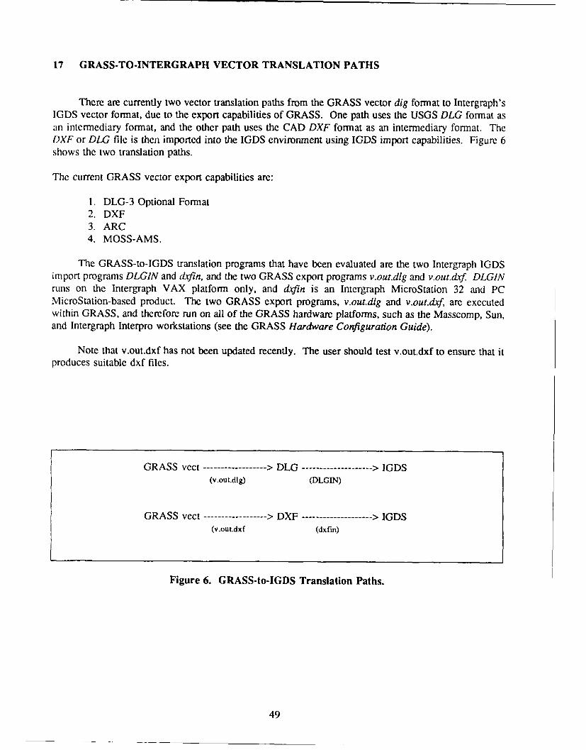
17 GRASS-TO-INTERGRAPH VECTOR TRANSLATION PATHS
There are currently two vector translation paths from the GRASS vector dig format to Intergraph'sIGDS vector format, due to the export capabilities of GRASS. One path uses the USGS DLG format asan intermediary format, and the other path uses the CAD DXF format as an intermediary format. TheDXF or DLG file is then imported into the IGDS environment using IGDS import capabilities. Figure 6shows the two translation paths.
The current GRASS vector export capabilities are:
1. DLG-3 Optional Format2. DXF3. ARC4. MOSS-AMS.
The GRASS-to-IGDS translation programs that have been evaluated are the two Intergraph IGDSimport programs DLGIN and dxfin, and the two GRASS export programs v.out.dlg and v.out.dxf. DLGINruns on the Intergraph VAX platform only, and din is an Intergraph MicroStation 32 and PCMicroStation-based product. The two GRASS export programs, v.out.dlg and v.out.d4f, are executedwithin GRASS, and therefore run on all of the GRASS hardware platforms, such as the Masscomp, Sun,and Intergraph Interpro workstations (see the GRASS Hardware Configuration Guide).
Note that v.out.dxf has not been updated recently. The user should test v.out.dxf to ensure that itproduces suitable dxf files.
GRASS vect ----------------- > DLG ------------------- > IGDS(v.out.dig) (DLGIN)
GRASS vect ----------------- > DXF ------------------- > IGDS(v.out.dxf (dxfin)
Figure 6. GRASS-to-IGDS Translation Paths.
49

18 CHOOSING DLG OR DXF AS AN INTERMEDIARY VECTOR FORMAT
The decision to use either DLG or DXF as an intermediary format is based on the capabilities ofthe GRASS export programs v.out.dxf and v.out.dlg,and the capabilities of the Intergraph import programsVAX DLGIN and MicroStation dxfin.
GRASS Export Programs
The output file created by v.out.dxf can be either larger or smaller than the output file created byv.out.dlg for the same GRASS digascii file (Table 3). Both GRASS programs output the files in ASCIIformat. (Chapter 20, "How To Export DLG and DXF Files From GRASS," p 51).
DLGIN
DLGIN is the Intergraph translator that translates USGS DLG data files to Intergraph StandardInterchange Format (ISIF) ASCII data files. The Standard DLG-3 distribution format and the OptionalDLG-3 distribution format are supported. The translator runs only on DLG-3 format data with the scalesof 1:2000000, 1:24000, or 1:00000. The DLG ASCII files can be translated into Standard IGDS designfiles using the Intergraph Standard Interchange Format (ISIF) software. (Refer to the Intergraph USGSDLGIN User's Guide). DLGIN has the option to translate up to 100 DLG files at a time, placing each ina separate design file. DLGIN also has the capability to create an Intergraph database DMRS.
The choice between vector translation paths when translating data from GRASS to IGDS dependson the available hardware and whether the user would like to identify the GRASS category attributes asfeature codes in the DLG-3 file, thus assigning them to ISIF attributes, and IGDS attributes with theassociated IGDS database (DMRS). The creation of two input parameter files are required by DLGIN,and a third parameter file if a DMRS database is desired.
dxfin
The Intergraph MicroStation translator dxfin translates DXF ASCII format to IGDS binary vectorformat. There is no option to assign the DXF levels, element symbology, or element type to an IGDSlevel, element symbology, or element type. DXF levels translate into the corresponding IGDS levels.This program is simple to use since no parameter files are required. This program is the best choice iftranslation of database attributes is not desired. (Refer to the Intergraph MicroStation Reference Guide.)
Chapter Summary
The output file created by v.out.dxf may be larger or smaller than the output file created by v.out.dlg(Table 6). GRASS export file size may not be a criterion for choosing the export program. The maindifference between the Intergraph programs DLGIN and dxfin, for translation decisions, is DLGIN's abilityto translate GRASS category attributes in the DLG-3 file to the ISIF format. One important factor is thattranslating the ISIF vector data into IGDS vector data requires an additional Intergraph ISIF program.
DLGIN is recommended if VAX hardware and software are available and if the user wishes to retainthe GRASS dig attributes during translation. dxfin is recommended in the absence of VAX hardware andsoftware, and if translation of GRASS attributes is not a priority.
50

19 EXPORTING DLG AND DXF FILES FROM GRASS
How To Export DLG Files From GRASS
The GRASS program v.out.dig translates GRASS binary vector files, called dig files, to the USGSDLG format called DLG-3 Optional format. The output DLG-3 Optional file is in ASCII format.
To run v.out.dlg, type "v.out.dlg" at the GRASS prompt. The user is prompted for the name of theGRASS binary vector file and the name of the resultant DLG file. When the program is complete, thenew DLG file will reside under the directory "dlg" in the current GRASS LOCATION and MAPSET.(Refer to the GRASS Reference Manual for further details.)
Summary of the GRASS-DLG-IGDS Translation Sequence
The procedure for translating GRASS vector data into IGDS vector format using the GRASSv.out.dlg program and the Intergraph VAX DLGIN program, to produce an ISIF vector fiie and then anIGDS vector file is:
1. Use the GRASS program v.transform to translate the UTM digascii file to a State Planedigascii file (see Chapter 11, "Coordinate Conversion in GRASS," p 39).
2. Run the GRASS programs v.in.ascii and v.support on the output file of v.transform to createa binary dig file with topology.
3. Run the GRASS program v.out.dlg to convert the dig file into an ASCII DLG-3 Optionalformatted file.
4. Transfer the ASCII DLG-3 file to an Intergraph VAX computer that has the Intergraphprograms DLGIN and ISIF installed.
5. Execute DLGIN (refer to Chapter 19, "Importing DLG and DXF Files into IGDS," p 53). Theoutput file will be in the ISIF.
6. Run the Intergraph VAX-based program named ISIF to convert the ISIF file to an IGDS file.
7. Display the IGDS file in the Intergraph VAX or MicroStation display graphics environment.
Ihow To Export DXF Files From GRASS
The GRASS program v.out.dxf translates GRASS ASCII vector files, called digascii files, to theASCII CADD DXF format. The program is a command line program in which the user types the programname followed by the required arguments. The syntax for the program is:
GRASS> v.out.dxf input = name output = name
where:input = vector ASCII input fileoutput = dxf output file.
51

The following example uses the GRASS Spearfish data base:
GRASS> v.out.dxf input = /data/foghom/spearfish/PERMANENT/dig-ascii/roads.asciioutput = roads.dxf
The output file (in this case roads.dxf) is placed in the current working directory. As with all GRASSprograms, the syntax of the program can be displayed on the screen by typing the program name and helpat the GRASS prompt and pressing Return. For further information consult the GRASS ReferenceManual.
Summary of the GRASS-DXF-IGDS Translation Sequence
The procedure for translating GRASS vector data into IGDS vector format, using the GRASSv.out.dxf program and the Intergraph MicroStation dxfin program to produce an IGDS vector file is:
1. Use the GRASS program v.transform to translate the UTM digascii file to a State Planedig ascii file (see Chapter 11, "Coordinate Conversion in GRASS," p 39).
2. Run the GRASS program v.out.drf to convert the digascii file to an ASCII DXF file (see"How to Export DXF Files From GRASS," p 51)
3. Transfer the ASCII DXF file to an Intergraph machine running MicroStation PC orMicroStation 32, if it is not already on one (GRASS runs on Intergraph Interpro 200, 300, 3000, and 6000series workstations. These workstations also run MicroStation 32).
4. Execute dxfin (refer to Chapter 21, "Importing DLG and DXF Files into IGDS," p 53). Theoutput file will be in the Intergraph Graphics Design Software (IGDS) format.
5. Display the IGDS file in the Intergraph VAX or MicroStation display graphics environment.
52

20 IMPORTING DLG AND DXF FILES INTO IGDS
flow To Run Intergraph DLGIN
The Intergraph translation program DLGIN runs on the Intergraph VAX - : -corn. After exportingthe GRASS dig filc to an ASCII DLG file, the DLG file can be networked or transferred to the VAX viamagnetic or optical medium and imported into IGDS using the DLGIN program (see Chapter 20,"Exporting DLG and DXF Files From GRASS," p 51). The full translation path using Intergraph DLGINwill be:
GRASS dig ---- > DLG ---- > ISIF ---- > IGDS
Two files are required to run VAX DLGIN on a DLG file. Both files are created by the user usinga screen text editor and are stored in a flat ASCII file. The first file is an ISIF Environment File. Thisis the control file which contains specifications for ISIF processing. The Intergraph DLGIN TranslatorUser's Guide does not describe this file, but refers the reader to the Standard Interchange FormatCommand Language Implementation User's Guide14 for details.
The second file is a DLGIN parameter file. It can be given any name by the user, for example,dlg.param. The full name in VAX VMS will then become dlg.param.;I Underbars should not be usedin the filename because this may cause confusion in the VMS operating system. The user will beprompted for the parameter filename when running DLGIN, and should type the full VMS filename,including the semicolon followed by the version number.
The parameter file allows the user to specify the IGDS element type, level, color, weight, andlinestyle to be associated with the DLG lines, areas, and nodes, and then to be placed in the IGDS designfile. If DLG nodes, areas, or lines are not given IGDS element characteristics in the parameter file,defaults are assigned. For a detailed description of the parameter file and a list of DLGIN defaults, referto the DLGIN Translator User's Guide.
DLGIN also has the capability to create IGDS attributes from a DLG file that is stored in theIntergraph VAX-based DMRS data base. This option of DLGIN was not evaluated in this study.
To execute the DLGIN translator, at the VAX prompt, type: "run pro-dd dlgin:dlgin" and thenfollow the interactive prompts described in the Intergraph DLGIN User's Guide.
How To Run Intergraph dxfln
dyfin is the lntcrgraph MicroStation-based program that translates DXF-formatted vector data toIGDS vector format. dxfin is a program that comes packaged with Intergraph MicroStation PC andIntergraph MicroStation 32.
The first step before running dxfin is to create an IGDS design file. The design file should be giventhe same name as the DXF file. For example, if the DXF file is named roads.dxf, the design file shouldbe given the name roads.dgn. If the design file is created on a VAX, create the file in the VAX home
Standard Interchange Formal Command Language, Implementation Guide, DTRN00I (Intergraph Corp., 1986).
53
directory. To create a new design file, either on a VAX or within MicroStation, type the followingsequence of commands:
$ ice (VAX) or mce (MicroStation)GRAPHICS: uti cre filename 2d 150UTILITIES: g filename.dgn
These commands create a two-dimensional design file having the namefilename with 150 blocks. IGDSworking units (MU, SU, and PU) and the global origin (go=) should be set as well according to the scaleand desired coordinate system (refer to the IGDS User's Guide).15 To exit the design file, select the Exitinterface option in MicroStation or the Uilities pop down menu on the VAX. Next, when on the VAX,select the "File Design" option and then press <control> z <return>. If the file was created on a VAX,transfer the file to a MicroStation platform through the network.
To execute dxfin, type "mce" at the $ prompt and enter the supplement library as follows:
$ mceGRAPHICS: utiUTILITIES: suppSUPPLEMENT: dxfin
You will be prompted for the DXF file name. When the program is complete the design file can bedisplayed in either the MicroStation or VAX IGDS environment. (For additional information refer to theIntergraph Microstation Reference Guide).
IS IGDS User's Guide, DNUC012 (Intergraph Corp., 1985).
54

REFERENCES
Bradshaw, Stuart, and Pamn Thompson, Options for Acquiring Elevation Data, Technical Manuscript (TM) N-89,20/ADA2200934(U.S. Army Construction Engineering Researcii Laboratory [USACERL], January 1989).
Brooks, Douglas. Michael Shapiro. and Mark Johnson, GRASS Hardware Configuration Guide, Automated Data Processing(ADP) Report N-89/21/ADA220954 (USACERL, March 1989).
EDG User's Guide, DSYS103 (Intergraph Corporation, 1987).
IGDS User's Guide, DNUC012 (Intergraph Corporation, 1985).
Intergraph DLGIN User's Guide, DMAP14410 (Intergraph Corporation, 1986).
Intergraph DLGOUT User's Guide, DMAP145 (Intergraph Corporation, 1986).
Intergraph MicroStation Reference Guide, DSA0271 10 (Intergraph Corporation, 1989).
baergraph Spatial Editor User's Guide, DMAP16520 (Intergraph Corporation, 1988).
Messersnith, Jean, "Map Preparation," in GRASS Reference Manual, by James Westervelt, et al., ADP Report N-87/22(USACERL, September 1988).
Shapiro, Michael, et al., GRASS Programmer's Manual, ADP Report N-89/14 (USACERL, September 1989).
Standard Interchange Format Command Language Implementation Guide, DTRN0O1 (Intergraph Corporation, 1986)
U.S. Department of the Interior, U.S. Geological Survey, Digital Line Graphs from 1:24000-Scale Maps (Department of theInterior, 1986).
Westervelt, James, et al., GRASS Reference Manual, ADP Report N-87/22 (USACERL, September 1988).
55

USACERL Distribution
Chief of Engineers Yakima Firing Center 98901 US Army Forts
A'TrN: CEIISC-IM-LH (2) Fort Belvcair, VA 22060AITN: CEHSC-IM-LP (2) USATHAMA 21010 AMTN: CEETL.CL-GC (2)
ATTN: CERD-L ATTN: CETHA-RM-I ATN! CETEC-CA-DATN: DAEN-ZCI-P (2) ATTN: AMXTH-RM ATTN: AMSELRD-NV-VMD-TST
ATTN: CECW-PF ATTN: CETHA-IR-S ATTN: Envr & Nat Res Div
ATTN: CECW-EP-S CEHSC 22060 Fort Monroe, VA 23651
ATTN: CFCW-RE ATrN: ATBO-GE
ATTN: CEIM- ATTN: CEHSC-FN ATTN: ATEN-FN
AI"N: CECW-OR ATN: CEHSC-SP Fort Dram 13603ATTN: CEHSC-FM-A ATTN: AFZS-EH-E
US Army Engineer District Bureau of Land ManagemntFort Jackson 292
ATITN: Chief, Regulatory Functions WASH DC 20240 Fort G An 30050
Buffalo 14207 Fr ilr 05Bofoalk 2350 Fort Collins 80526 ATTN: FCEN-CED-ENorfolk 23510 Denver 80225
Huntington 25701 Fort Gordon 30905Wilmington 28402 US Dept of Commerce 20233 ATTN: ATZH-DIE (2)Charleston 29402 Fort Stewart 31314ATMN: AFZP-DEN-W
St. Paul 55101 Army National Guard 20310 Fort Bemning 31905Chicago 60606 ATTN: NGB-ARECLittle Rock 72203 ATTN: Nat. Resource Mgmt Div (2)
Galveston 77550 US Army Concepts Analysis Agency 20814 Fort McClellan 36205Albuquenque 87103 ATTN: ATZN-FEELos Angeles 90053 FBI Academy 22135 Fort Rucker 36362San Francisco 94105 USA Foreign Science Tech Car 22901 ATTN: ATZQ-EHSacramento 95814 Fort Knox 40121Portland 97208 Naval Oceanographic Office 39522 ATTN: ATZK-EHESeattle 99362 Redstone Arsenal 35898 Fort Campbll 42223New England 02254 ATTN: AMSMI-RA-EH-MP-PC ATIN: AFZH-DEHAfN: CENED-OD-R Fort Benjamin Harrison 46216
New York 10278 CEWES A TN: ATI-ISP (2)AITN: CENAN ATTN: CEWES-IM-DA 39181 Fort McCoy 54656
Philadelphia 19106 ATN: CADD Center 39180AFZR-DENATTN: CENAP Fort Riley 66442
Baltimore 21203 Wright-Pasteson AFB 45433 ATTN: AFZN-DE-N (2)AIIN: CENAB-OP-R ATTN:mSon AB Fort Chaffee 72905
Savannah 31402 ATMN: NSBITAL/OEBN ATN: ATZR-ZFE (2)ATTN: CESAS-OP-FP Michigan Dept of Military Affairs 48913 Fort Sill 73503
Jacksonville 32232 ATTN: Fish & Wildlfe Br (2)ATN: CESAJ-R-RD Twin Cities Army Ammo Plant (2) 55112 Fort Leonard Wood 65473
Mobile 36628 ATTN: ATZI'-DEH-EEATIN: CESAM-OP.S Fort Dix 08640Nsvle322Camp Ripley 56345 ATT'IN: ATZD-EHlNNashville 37202 ATTN: Ofc of Archeology & Engr (2) AT:AZ-H
ATTN: CEORN Fort Eustis 23604Memphis 38103 9ATTN: Ranges & Targets DirAeTphN 38103 CO 5th lnf. Fort Polk 71459 Fort Worth 76115
ATrN: CEI.MM-CO-R ATTN: Envr & Nat Rgfcs Mgmt Div (2) Fr ot 61
Vicksburg 39180 ATTN: Cartographic Ctr (2)AIl'N: CILMV US Army Materiel Cmd 61299 Fort Hood 76544
Louisville 40201 AM: AMXEN-U (2) ATTN: AFZF-DE-ENVATI'N: CEORL Fort Bliss 79916
Detroit C8C2 C US Army Europe ATTN: ATZC-DEH-EATIN: CENCE-CO USAr 09403 Fort Carson 80913
Rock Island 61204 ATTN: US AE () ATTN: AFZC-ECM-NRATIN: 6120 ATI'N: AEAEN-FE-E (2) Fort Huachucs 85613AT:C CRV Corps 09079 ATrN: AITS-EHB
St. Louis 63101 ATTN: AETV-EHF-RATTN: CELMS-OD-F Fort Irwin 92310
Kansas City 64106 Texas Army Nat'l Guard 78763 ATrtN: AFJ-EHAITN: Chief. Permits Section Fort Lewis 98433
Omaha 68102 Lone Star Army Ammo Plant 75505 ATTN: AFZH-DEQATTN: CEMRO-OP ATTN: ATZH-EHQ
New Orleans 71060 Red River Army Depot Fort Richardson 99505A*rrN: Chief, Permits Section ATIN SDSRR-GB 75507 AMN: DER
Tulsa 74121 Fort Bragg 28307ATIN: CEWST ATTN: DEHi
Fort Worth 76102 Dugway Proving Ground 94122
A'TN: CESWF-OD-O ATTN: DPG-EN.E (2) National Weather Service 20910US Anny lDivisions Yuma Proving Ground 85365 US Geological Survey 22092
liAny ngr DisosATTN: ATEYP.ES-E
North Central 60606A'IrN: CI'NCD-CO Pine Bluff Arsenal 17602Sotws 5'White Sands Mlissile Range AIN MP-M
Southwest 75242 AATI'N: CESWD-CO-R AllN: STEWS-ESE 88002
S6Env Re e & Info r US Army Cold Regions Research & Engr LabUS Military Academy 10996 ANv : ResponsEP 20InoC 0 ATTIN: CECRL-IS 03755
ATTN: Dept of Geo & Envr Engr (2) ATTN: ENVR-EP 20310
A'ITN: Natural Resources Branch Nat' Geophysical Data Ctr NASA/SSC/STL 39529
Aberdeen Proving Ground, MD 21005 ATTN: C 8003Defense Technical Info CenterATTN: ISC-TECOM IlohenfelsTraining Area 09173 ATTN: DTIC-FAB (2)ATrN: IISiB.C! ATTN: AETTI.DEH 144
US EPA Research Lab 97333 ATTN: AE4l/9-DEH-ENV-AP +174)92
'Ilhis publication was reproduced on recycled paper.