Embed Size (px)
Citation preview
GPD 505Technical Manual
MagneTek
- i -
GPD 505 SIMPLIFIED START-UP PROCEDURE
This procedure will quickly get you up and running using the Digital Operator keypad or a usersupplied remote operator control. It assumes that the GPD 505 and motor are correctly wired(see pages 1-12 thru 1-15), and start-up is to be performed without any changes to factory setparameters. Detailed information on the many other features of this drive will be found in latersections of this manual.
INSTALLATION
1 . Be certain your input voltage source, motor, and drive name plates are all marked either 230Vor 460V. Other voltages can be used, but require additional programming; see Section 5.
2 . Mount drive on a vertical surface with adequate space for air circulation.
3 . Remove front cover with Digital Operator, fit conduit to bottom plate, and connect power andground wires as shown.
CAUTIONBe certain you connect input power to terminals L1, L2, and L3 only, or serious damagewill result. Connect motor to terminals T1, T2, and T3 only.
KEYPAD OPERATION
1 . Replace front cover and Digi ta l Operator and apply input power - Keypad displayshows " 0.0 " ; REMOTE SEQ & REF LEDS and STOP/RESET LED are on, and F r e f FunctionLED is lit.
2 . Select LOCAL Mode by pressing LOCAL/REMOTE key - REMOTE SEQ & REF LEDswill go out.
3 . Enter Frequency Reference - Pressing the “up arrow” key will increase displayedfrequency value; pressing the “down arrow” will decrease the displayed value. Increase thefrequency reference display to " 6.0 " (Hz). Press the ENTER key to store or write this valueto the drive.
4 . View the Drive Output Frequency - Press the DSPL key once. The F r e f Function LEDwill go out, and the Fout Function LED will turn on.
5 . Run Forward - Press the RUN key. The motor should run at 10% (6/60) of its basespeed; the RUN LED will turn on, and the STOP/RESET LED will go out.NOTE: If the direction of motor rotation is incorrect, press the STOP/RESET key. Whenmotor has stopped, remove power, wait for the “CHARGE” light to go out, remove the drivecover and switch the motor leads at terminals T1 & T2. Replace drive cover and re-applyinput power.
6 . Change Frequency - Press the DSPL key repeatedly until the F r e f Function LED turns on.A new frequency reference can be set by using the “up arrow” and “down arrow” keys as instep 3. Note that the drive responds to each new value only after the ENTER key is pressed(unless parameter n009 is set to " 0 ", in which case the ENTER key-press is not needed).
7 . Revers ing - can be selected either while stopped or while running. With the drive stopped,press the DSPL key repeatedly until the F / R Function LED turns on, then press the ENTERkey. Display will read " For ". Press either the “up arrow” or “down arrow” key to togglethis display to " rEu ", for reverse motor operation. Then press ENTER again to store thenew selection. If the drive is running when this change is entered, the drive will deceleratethe motor to 0 Hz, then accelerate the motor to the same speed in the opposite direction. Thiscan be done while running, provided your machine can be operated in reverse directionwithout damage.
8 . Displays - With the drive stopped, each time the DSPL key is pressed, a different functiondisplay appears (as indicated by the Function LED which is turned on). The first function onpower-up is the F r e f LED and " 0.0 " display, discussed above. Press DSPL, and the FoutLED turns on and F r e f goes out; the display now shows output frequency (speed). The nextfunction is I o u t, and indicates drive output current (in Amps). For more information, referto Section 4 of this manual.
9 . Faul ts - If an unacceptable operating condition such as code Ou (overvoltage), U u ( u n d e r -voltage), OC (overcurrent), etc. occurs, the drive will trip, and the motor will coast to a stop.The appropriate fault code will be displayed. Examine the fault code; then consult Sections 6 &7 for fault correction procedure.
INSTALLATION OF EXTERNAL RUN/STOP SWITCH AND SPEED POTENTIOMETERS
IMPORTANT: Complete the INSTALLATION and KEYPAD OPERATION instructions before attempting external control.
1 . Disconnect power, remove drive front cover with Digital Operator, and wait for “CHARGE”light to go out.
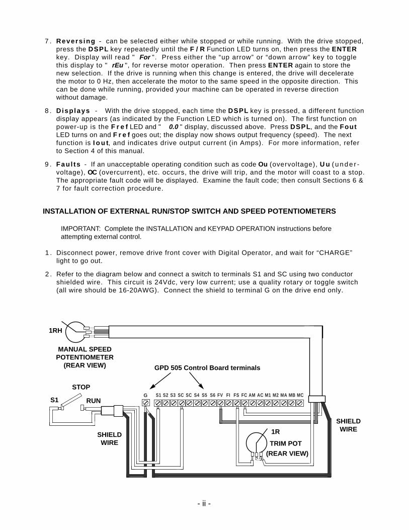
2 . Refer to the diagram below and connect a switch to terminals S1 and SC using two conductorshielded wire. This circuit is 24Vdc, very low current; use a quality rotary or toggle switch(all wire should be 16-20AWG). Connect the shield to terminal G on the drive end only.
- ii -
S1 S2 S3 SC SC S4 S5 S6 FV FI FS FC AM AC M1 M2 MA MB MCGS1
STOP
RUN
SHIELDWIRE
1RH
MANUAL SPEEDPOTENTIOMETER
(REAR VIEW)
SHIELDWIRE
GPD 505 Control Board terminals
1R
TRIM POT
(REAR VIEW)
3 . Connect a manual speed potentiometer rated 2000-3000 ohms, 1 watt minimum, using threeconductor shielded wire, with shield connected at terminal G. Connect wires to thepotentiometer as shown, viewing potentiometer from the back. Trace wire shown closest tothe top in diagram (right side of potentiometer) and connect to terminal FC. Trace center wireof potentiometer through and connect to terminal FV. The remaining wire will be connected tothe trim pot in step 4.
4 . Connect a trim potentiometer rated 2000-3000 ohms, 1 watt minimum, as close to the driveterminals as possible. Viewing the potentiometer from the back, connect a single conductorwire from the left terminal to terminal FS of the drive. Connect a short jumper wire betweenthe center and right terminals. Connect remaining wire from manual speed pot as shown.
5 . Replace drive front cover and Digital Operator. Make sure remote switch S1 is in “Stop”position, then apply power. Note that the STOP lamp is on. Press LOCAL/REMOTE key, sothat the REMOTE SEQ & REF LEDs turn on.
6 . Calibrate manual speed pot for maximum speed at maximum rotation. With switch S1 in the“Stop” position, press DISPL key repeatedly until the F r e f LED turns on. The display willindicate the combined setting of the trim and manual speed pots; it should read " 60.0 " w i thboth pots (as viewed from the back) turned to their fully CW (maximum) settings. Turn thetrim pot slowly (CCW) until the F r e f display begins to decrease, then turn it back justenough to display " 60.0 ". Now the display should decrease as soon as the manual speed pot isturned slightly CCW.
7 . Press DISPL key repeatedly until the Fout LED turns on. Turn switch S1 to “Run”, andadjust motor speed with manual speed pot.
- iii -
PARAMETER FACTORY USER PARA.NUMBER (7) SETTING SETTING REF.
PARAMETER FACTORY USER PARA.NUMBER (7) SETTING SETTING REF.
PARAMETER FACTORY USER PARA.NUMBER (7) SETTING SETTING REF.
- iv -
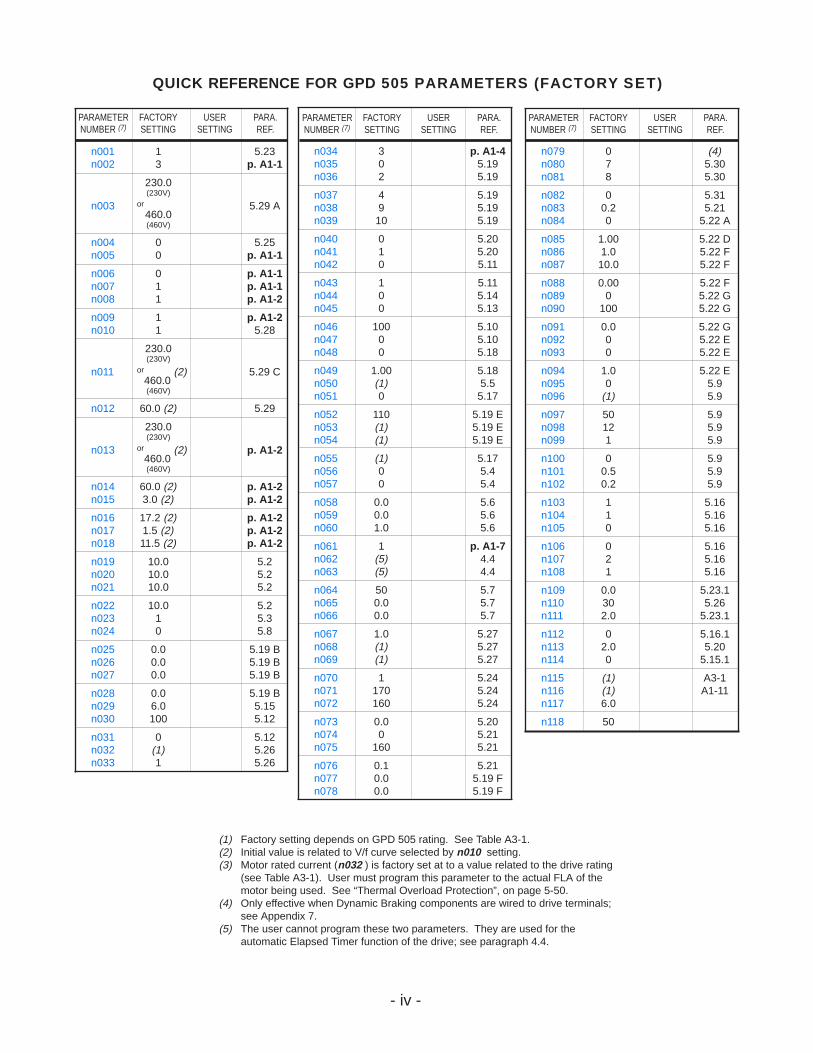
QUICK REFERENCE FOR GPD 505 PARAMETERS (FACTORY SET)
n079 0 (4)n080 7 5.30n081 8 5.30
n082 0 5.31n083 0.2 5.21n084 0 5.22 A
n085 1.00 5.22 Dn086 1.0 5.22 Fn087 10.0 5.22 F
n088 0.00 5.22 Fn089 0 5.22 Gn090 100 5.22 G
n091 0.0 5.22 Gn092 0 5.22 En093 0 5.22 E
n094 1.0 5.22 En095 0 5.9n096 (1) 5.9
n097 50 5.9n098 12 5.9n099 1 5.9
n100 0 5.9n101 0.5 5.9n102 0.2 5.9
n103 1 5.16n104 1 5.16n105 0 5.16
n106 0 5.16n107 2 5.16n108 1 5.16
n109 0.0 5.23.1n110 30 5.26n111 2.0 5.23.1
n112 0 5.16.1n113 2.0 5.20n114 0 5.15.1
n115 (1) A3-1n116 (1) A1-11n117 6.0
n118 50
n034 3 p. A1-4n035 0 5.19n036 2 5.19
n037 4 5.19n038 9 5.19n039 10 5.19
n040 0 5.20n041 1 5.20n042 0 5.11
n043 1 5.11n044 0 5.14n045 0 5.13
n046 100 5.10n047 0 5.10n048 0 5.18
n049 1.00 5.18n050 (1) 5.5n051 0 5.17
n052 110 5.19 En053 (1) 5.19 En054 (1) 5.19 E
n055 (1) 5.17n056 0 5.4n057 0 5.4
n058 0.0 5.6n059 0.0 5.6n060 1.0 5.6
n061 1 p. A1-7n062 (5) 4.4n063 (5) 4.4
n064 50 5.7n065 0.0 5.7n066 0.0 5.7
n067 1.0 5.27n068 (1) 5.27n069 (1) 5.27
n070 1 5.24n071 170 5.24n072 160 5.24
n073 0.0 5.20n074 0 5.21n075 160 5.21
n076 0.1 5.21n077 0.0 5.19 Fn078 0.0 5.19 F
n001 1 5.23n002 3 p. A1-1
230.0(230V)
orn003 460.0
5.29 A
(460V)
n004 0 5.25n005 0 p. A1-1
n006 0 p. A1-1n007 1 p. A1-1n008 1 p. A1-2
n009 1 p. A1-2n010 1 5.28
230.0(230V)
orn011 460.0
(2) 5.29 C
(460V)
n012 60.0 (2) 5.29
230.0(230V)
orn013 460.0
(2) p. A1-2
(460V)
n014 60.0 (2) p. A1-2n015 3.0 (2) p. A1-2
n016 17.2 (2) p. A1-2n017 1.5 (2) p. A1-2n018 11.5 (2) p. A1-2
n019 10.0 5.2n020 10.0 5.2n021 10.0 5.2
n022 10.0 5.2n023 1 5.3n024 0 5.8
n025 0.0 5.19 Bn026 0.0 5.19 Bn027 0.0 5.19 B
n028 0.0 5.19 Bn029 6.0 5.15n030 100 5.12
n031 0 5.12n032 (1) 5.26n033 1 5.26
(1) Factory setting depends on GPD 505 rating. See Table A3-1.(2) Initial value is related to V/f curve selected by n010 setting.(3) Motor rated current (n032 ) is factory set at to a value related to the drive rating
(see Table A3-1). User must program this parameter to the actual FLA of themotor being used. See “Thermal Overload Protection”, on page 5-50.
(4) Only effective when Dynamic Braking components are wired to drive terminals;see Appendix 7.
(5) The user cannot program these two parameters. They are used for theautomatic Elapsed Timer function of the drive; see paragraph 4.4.
-v-
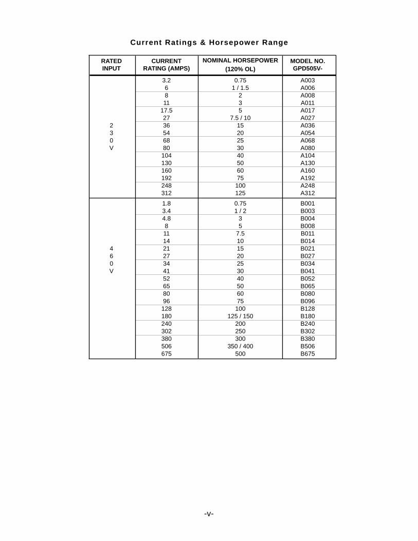
Current Ratings & Horsepower Range
RATED CURRENT NOMINAL HORSEPOWER MODEL NO.INPUT RATING (AMPS) (120% OL) GPD505V-
3.2 0.75 A0036 1 / 1.5 A0068 2 A00811 3 A011
17.5 5 A01727 7.5 / 10 A027
2 36 15 A0363 54 20 A0540 68 25 A068V 80 30 A080
104 40 A104130 50 A130160 60 A160192 75 A192248 100 A248312 125 A312
1.8 0.75 B0013.4 1 / 2 B0034.8 3 B0048 5 B00811 7.5 B01114 10 B014
4 21 15 B0216 27 20 B0270 34 25 B034V 41 30 B041
52 40 B05265 50 B06580 60 B08096 75 B096128 100 B128180 125 / 150 B180240 200 B240302 250 B302380 300 B380506 350 / 400 B506675 500 B675
-vi-
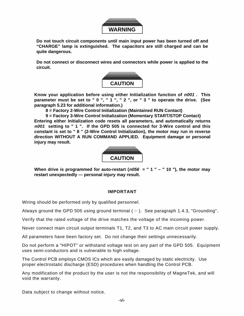
WARNING
Do not touch circuit components until main input power has been turned off and“CHARGE” lamp is extinguished. The capacitors are still charged and can bequite dangerous.
Do not connect or disconnect wires and connectors while power is applied to thecircuit.
CAUTION
Know your application before using either Initialization function of n001 . Thisparameter must be set to " 0 ", " 1 ", " 2 ", or " 3 " to operate the drive. (Seeparagraph 5.23 for additional information.)
8 = Factory 2-Wire Control Initialization (Maintained RUN Contact)9 = Factory 3-Wire Control Initialization (Momentary START/STOP Contact)
Entering either Initialization code resets all parameters, and automatically returnsn001 setting to " 1 ". If the GPD 505 is connected for 3-Wire control and thisconstant is set to " 8 " (2-Wire Control Initialization), the motor may run in reversedirection WITHOUT A RUN COMMAND APPLIED. Equipment damage or personalinjury may result.
CAUTION
When drive is programmed for auto-restart (n056 = " 1 " – " 10 "), the motor mayrestart unexpectedly — personal injury may result.
IMPORTANT
Wiring should be performed only by qualified personnel.
Always ground the GPD 505 using ground terminal ( ). See paragraph 1.4.3, "Grounding".
Verify that the rated voltage of the drive matches the voltage of the incoming power.
Never connect main circuit output terminals T1, T2, and T3 to AC main circuit power supply.
All parameters have been factory set. Do not change their settings unnecessarily.
Do not perform a “HIPOT” or withstand voltage test on any part of the GPD 505. Equipmentuses semi-conductors and is vulnerable to high voltage.
The Control PCB employs CMOS ICs which are easily damaged by static electricity. Useproper electrostatic discharge (ESD) procedures when handling the Control PCB.
Any modification of the product by the user is not the responsibility of MagneTek, and willvoid the warranty.
Data subject to change without notice.
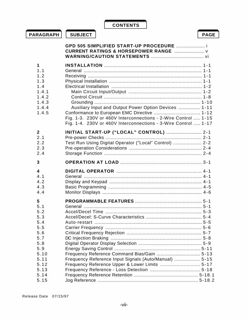
GPD 505 SIMPLIFIED START-UP PROCEDURE ..................... iCURRENT RATINGS & HORSEPOWER RANGE ...................... vWARNING/CAUTION STATEMENTS ....................................... vi
1 INSTALLATION ........................................................................ 1 -11 .1 General ....................................................................................... 1 -11 .2 Receiving .................................................................................... 1 -11 .3 Physical Installation .................................................................... 1 -11 .4 Electrical Installation .................................................................. 1 -21.4.1 Main Circuit Input/Output ...................................................... 1 -21.4.2 Control Circuit ........................................................................ 1 -81.4.3 Grounding .............................................................................. 1 -101.4.4 Auxiliary Input and Output Power Option Devices ................ 1 -111.4.5 Conformance to European EMC Directive .................................. 1 -12
Fig. 1-3. 230V or 460V Interconnections - 2-Wire Control ..... 1 -15Fig. 1-4. 230V or 460V Interconnections - 3-Wire Control ..... 1 -17
2 INITIAL START-UP (“LOCAL” CONTROL) .......................... 2 -12 .1 Pre-power Checks ....................................................................... 2 -12 .2 Test Run Using Digital Operator ("Local" Control) ..................... 2 -22 .3 Pre-operation Considerations ..................................................... 2 -42 .4 Storage Function ........................................................................ 2 -4
3 OPERATION AT LOAD ............................................................ 3 -1
4 DIGITAL OPERATOR ............................................................... 4 -14 .1 General ....................................................................................... 4 -14 .2 Display and Keypad .................................................................... 4 -14 .3 Basic Programming ..................................................................... 4 -54 .4 Monitor Displays ......................................................................... 4 -6
5 PROGRAMMABLE FEATURES ................................................. 5 -15 .1 General ....................................................................................... 5 -15 .2 Accel/Decel Time ....................................................................... 5 -35 .3 Accel/Decel: S-Curve Characteristics ......................................... 5 -45 .4 Auto-restart ............................................................................... 5 -55 .5 Carrier Frequency ....................................................................... 5 -65 .6 Critical Frequency Rejection ....................................................... 5 -75 .7 DC Injection Braking ................................................................... 5 -85 .8 Digital Operator Display Selection .............................................. 5 -95 .9 Energy Saving Control ............................................................... 5 -115.10 Frequency Reference Command Bias/Gain ................................ 5 -135.11 Frequency Reference Input Signals (Auto/Manual) ................... 5 -155.12 Frequency Reference Upper & Lower Limits ............................. 5 -175.13 Frequency Reference - Loss Detection ..................................... 5 -185.14 Frequency Reference Retention ............................................... 5-18.15.15 Jog Reference .......................................................................... 5-18.2
-vii-
Release Date 07/15/97
CONTENTS
SUBJECTPARAGRAPH PAGE

-viii- (THIS PAGE INTENTIONALLY BLANK)
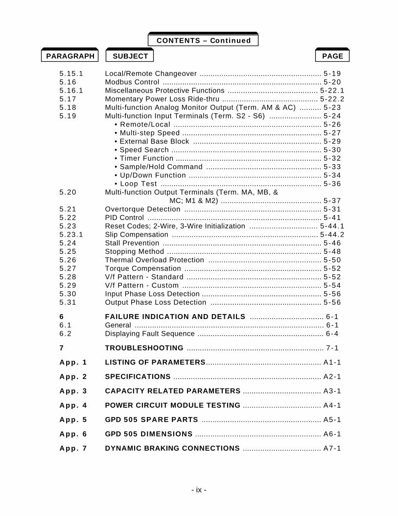
- ix -
5.15.1 Local/Remote Changeover ........................................................ 5 -195.16 Modbus Control ......................................................................... 5 -205.16.1 Miscellaneous Protective Functions ......................................... 5-22.15.17 Momentary Power Loss Ride-thru ............................................ 5-22.25.18 Multi-function Analog Monitor Output (Term. AM & AC) .......... 5 -235.19 Multi-function Input Terminals (Term. S2 - S6) ........................ 5 -24
• Remote/Local .................................................................... 5 -26• Multi-step Speed ................................................................ 5 -27• External Base Block ........................................................... 5 -29• Speed Search ..................................................................... 5 -30• Timer Function ................................................................... 5 -32• Sample/Hold Command ..................................................... 5 -33• Up/Down Function ............................................................. 5 -34• Loop Test .......................................................................... 5 -36
5.20 Multi-function Output Terminals (Term. MA, MB, & MC; M1 & M2) .............................................. 5 -37
5.21 Overtorque Detection ............................................................... 5 -315.22 PID Control ................................................................................ 5 -415.23 Reset Codes; 2-Wire, 3-Wire Initialization ............................... 5-44.15.23.1 Slip Compensation ................................................................... 5-44.25.24 Stall Prevention ......................................................................... 5 -465.25 Stopping Method ....................................................................... 5 -485.26 Thermal Overload Protection .................................................... 5 -505.27 Torque Compensation ............................................................... 5 -525.28 V/f Pattern - Standard .............................................................. 5 -525.29 V/f Pattern - Custom ................................................................ 5 -545.30 Input Phase Loss Detection ....................................................... 5 -565.31 Output Phase Loss Detection ................................................... 5 -56
6 FAILURE INDICATION AND DETAILS .................................. 6 -16 .1 General ....................................................................................... 6 -16 .2 Displaying Fault Sequence .......................................................... 6 -4
7 TROUBLESHOOTING ............................................................... 7 -1
A p p . 1 LISTING OF PARAMETERS ..................................................... A1-1
A p p . 2 SPECIFICATIONS .................................................................... A2-1
A p p . 3 CAPACITY RELATED PARAMETERS .................................... A3-1
A p p . 4 POWER CIRCUIT MODULE TESTING .................................... A4-1
A p p . 5 GPD 505 SPARE PARTS ....................................................... A5-1
A p p . 6 GPD 505 DIMENSIONS .......................................................... A6-1
A p p . 7 DYNAMIC BRAKING CONNECTIONS .................................... A7-1
SUBJECT PAGE
CONTENTS – Continued
PARAGRAPH
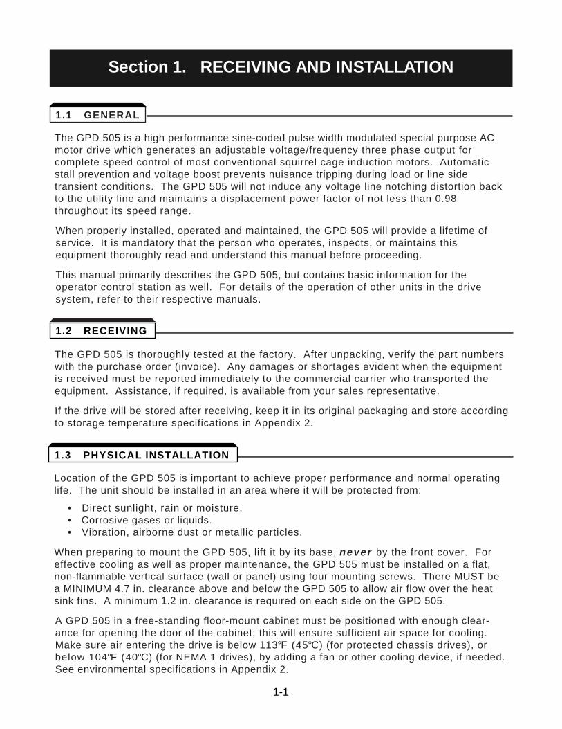
The GPD 505 is a high performance sine-coded pulse width modulated special purpose ACmotor drive which generates an adjustable voltage/frequency three phase output forcomplete speed control of most conventional squirrel cage induction motors. Automaticstall prevention and voltage boost prevents nuisance tripping during load or line sidetransient conditions. The GPD 505 will not induce any voltage line notching distortion backto the utility line and maintains a displacement power factor of not less than 0.98throughout its speed range.
When properly installed, operated and maintained, the GPD 505 will provide a lifetime ofservice. It is mandatory that the person who operates, inspects, or maintains thisequipment thoroughly read and understand this manual before proceeding.
This manual primarily describes the GPD 505, but contains basic information for theoperator control station as well. For details of the operation of other units in the drivesystem, refer to their respective manuals.
The GPD 505 is thoroughly tested at the factory. After unpacking, verify the part numberswith the purchase order (invoice). Any damages or shortages evident when the equipmentis received must be reported immediately to the commercial carrier who transported theequipment. Assistance, if required, is available from your sales representative.
If the drive will be stored after receiving, keep it in its original packaging and store accordingto storage temperature specifications in Appendix 2.
Location of the GPD 505 is important to achieve proper performance and normal operatinglife. The unit should be installed in an area where it will be protected from:
• Direct sunlight, rain or moisture.• Corrosive gases or liquids.• Vibration, airborne dust or metallic particles.
When preparing to mount the GPD 505, lift it by its base, never by the front cover. Foreffective cooling as well as proper maintenance, the GPD 505 must be installed on a flat,non-flammable vertical surface (wall or panel) using four mounting screws. There MUST bea MINIMUM 4.7 in. clearance above and below the GPD 505 to allow air flow over the heatsink fins. A minimum 1.2 in. clearance is required on each side on the GPD 505.
A GPD 505 in a free-standing floor-mount cabinet must be positioned with enough clear-ance for opening the door of the cabinet; this will ensure sufficient air space for cooling.Make sure air entering the drive is below 113°F (45°C) (for protected chassis drives), orbelow 104°F (40°C) (for NEMA 1 drives), by adding a fan or other cooling device, if needed.See environmental specifications in Appendix 2.
1-1
Section 1. RECEIVING AND INSTALLATION
1.1 GENERAL
1.2 RECEIVING
1.3 PHYSICAL INSTALLATION
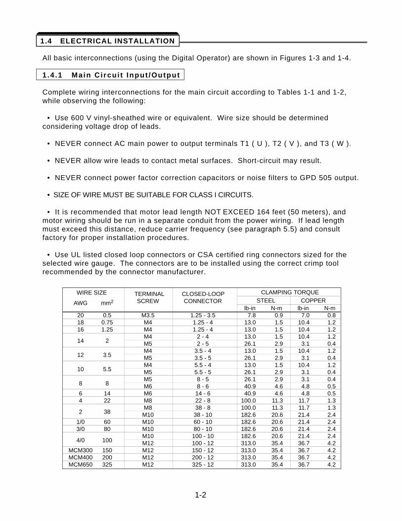
All basic interconnections (using the Digital Operator) are shown in Figures 1-3 and 1-4.
1.4 .1 Main Ci rcui t Input /Output
Complete wiring interconnections for the main circuit according to Tables 1-1 and 1-2,while observing the following:
• Use 600 V vinyl-sheathed wire or equivalent. Wire size should be determinedconsidering voltage drop of leads.
• NEVER connect AC main power to output terminals T1 ( U ), T2 ( V ), and T3 ( W ).
• NEVER allow wire leads to contact metal surfaces. Short-circuit may result.
• NEVER connect power factor correction capacitors or noise filters to GPD 505 output.
• SIZE OF WIRE MUST BE SUITABLE FOR CLASS I CIRCUITS.
• It is recommended that motor lead length NOT EXCEED 164 feet (50 meters), andmotor wiring should be run in a separate conduit from the power wiring. If lead lengthmust exceed this distance, reduce carrier frequency (see paragraph 5.5) and consultfactory for proper installation procedures.
• Use UL listed closed loop connectors or CSA certified ring connectors sized for theselected wire gauge. The connectors are to be installed using the correct crimp toolrecommended by the connector manufacturer.
WIRE SIZE TERMINAL CLOSED-LOOP CLAMPING TORQUE
AWG mm2 SCREW CONNECTOR STEEL COPPERlb-in N-m lb-in N-m
20 0.5 M3.5 1.25 - 3.5 7.8 0.9 7.0 0.818 0.75 M4 1.25 - 4 13.0 1.5 10.4 1.216 1.25 M4 1.25 - 4 13.0 1.5 10.4 1.2
M4 2 - 4 13.0 1.5 10.4 1.214 2 M5 2 - 5 26.1 2.9 3.1 0.4
M4 3.5 - 4 13.0 1.5 10.4 1.212 3.5 M5 3.5 - 5 26.1 2.9 3.1 0.4
M4 5.5 - 4 13.0 1.5 10.4 1.210 5.5 M5 5.5 - 5 26.1 2.9 3.1 0.4
M5 8 - 5 26.1 2.9 3.1 0.48 8 M6 8 - 6 40.9 4.6 4.8 0.56 14 M6 14 - 6 40.9 4.6 4.8 0.54 22 M8 22 - 8 100.0 11.3 11.7 1.3
M8 38 - 8 100.0 11.3 11.7 1.32 38 M10 38 - 10 182.6 20.6 21.4 2.4
1/0 60 M10 60 - 10 182.6 20.6 21.4 2.43/0 80 M10 80 - 10 182.6 20.6 21.4 2.4
M10 100 - 10 182.6 20.6 21.4 2.44/0 100 M12 100 - 12 313.0 35.4 36.7 4.2
MCM300 150 M12 150 - 12 313.0 35.4 36.7 4.2MCM400 200 M12 200 - 12 313.0 35.4 36.7 4.2MCM650 325 M12 325 - 12 313.0 35.4 36.7 4.2
1-2
1.4 ELECTRICAL INSTALLATION
1-3
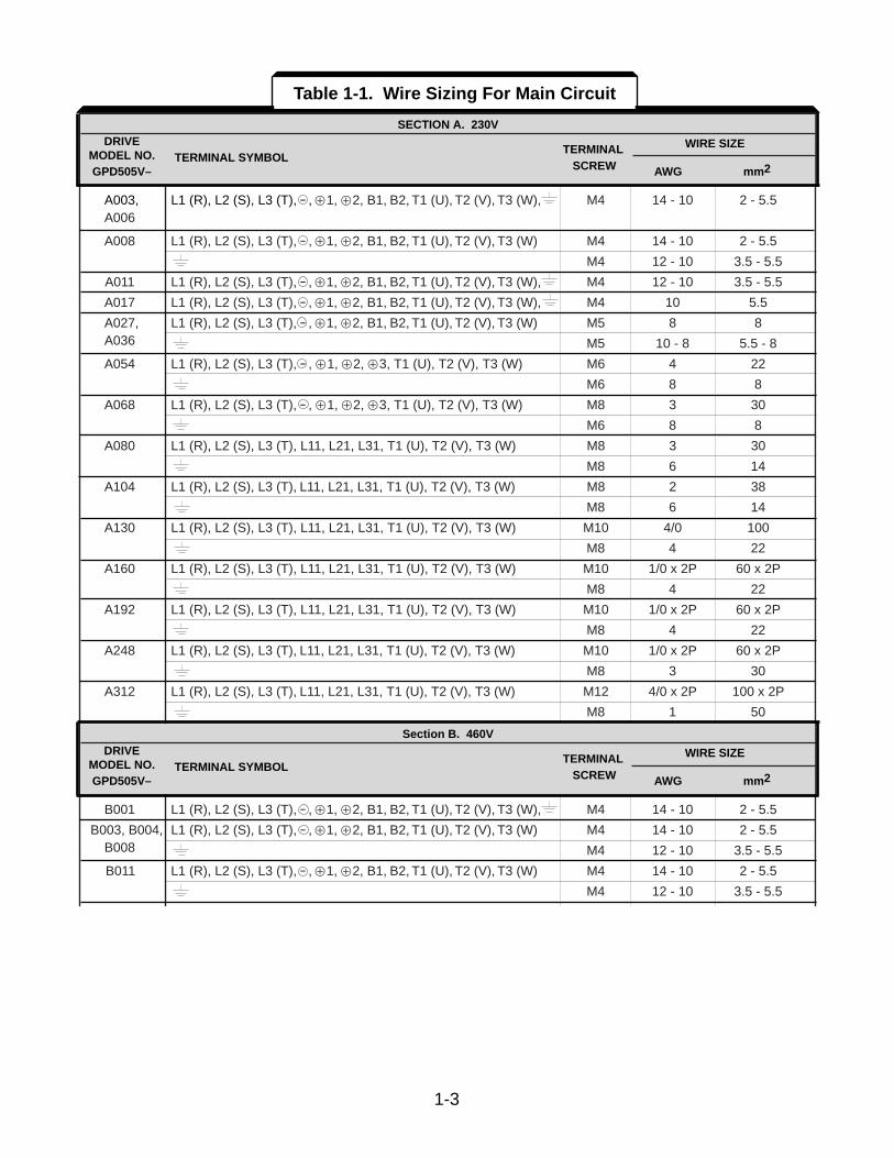
HP TERMINAL WIRE SIZERATING TERMINAL SYMBOL SCREW AWG MM2
A003, L1 (R), L2 (S), L3 (T), - , Å1, Å2, B1, B2, T1 (U), T2 (V), T3 (W), M4 14 - 10 2 - 5.5A006
A008 L1 (R), L2 (S), L3 (T), - , Å1, Å2, B1, B2, T1 (U), T2 (V), T3 (W) M4 14 - 10 2 - 5.5
M4 12 - 10 3.5 - 5.5
A011 L1 (R), L2 (S), L3 (T), - , Å1, Å2, B1, B2, T1 (U), T2 (V), T3 (W), M4 12 - 10 3.5 - 5.5
A017 L1 (R), L2 (S), L3 (T), - , Å1, Å2, B1, B2, T1 (U), T2 (V), T3 (W), M4 10 5.5
A027, L1 (R), L2 (S), L3 (T), - , Å1, Å2, B1, B2, T1 (U), T2 (V), T3 (W) M5 8 8A036 M5 10 - 8 5.5 - 8
A054 L1 (R), L2 (S), L3 (T), - , Å1, Å2, Å3, T1 (U), T2 (V), T3 (W) M6 4 22
M6 8 8
A068 L1 (R), L2 (S), L3 (T), - , Å1, Å2, Å3, T1 (U), T2 (V), T3 (W) M8 3 30
M6 8 8
A080 L1 (R), L2 (S), L3 (T), L11, L21, L31, T1 (U), T2 (V), T3 (W) M8 3 30
M8 6 14
A104 L1 (R), L2 (S), L3 (T), L11, L21, L31, T1 (U), T2 (V), T3 (W) M8 2 38
M8 6 14
A130 L1 (R), L2 (S), L3 (T), L11, L21, L31, T1 (U), T2 (V), T3 (W) M10 4/0 100
M8 4 22
A160 L1 (R), L2 (S), L3 (T), L11, L21, L31, T1 (U), T2 (V), T3 (W) M10 1/0 x 2P 60 x 2P
M8 4 22
A192 L1 (R), L2 (S), L3 (T), L11, L21, L31, T1 (U), T2 (V), T3 (W) M10 1/0 x 2P 60 x 2P
M8 4 22
A248 L1 (R), L2 (S), L3 (T), L11, L21, L31, T1 (U), T2 (V), T3 (W) M10 1/0 x 2P 60 x 2P
M8 3 30
A312 L1 (R), L2 (S), L3 (T), L11, L21, L31, T1 (U), T2 (V), T3 (W) M12 4/0 x 2P 100 x 2P
M8 1 50
DRIVE TERMINAL WIRE SIZEMODEL NO. TERMINAL SYMBOL SCREW AWG mm2
B001 L1 (R), L2 (S), L3 (T), - , Å1, Å2, B1, B2, T1 (U), T2 (V), T3 (W), M4 14 - 10 2 - 5.5
B003, B004, L1 (R), L2 (S), L3 (T), - , Å1, Å2, B1, B2, T1 (U), T2 (V), T3 (W) M4 14 - 10 2 - 5.5B008 M4 12 - 10 3.5 - 5.5
B011 L1 (R), L2 (S), L3 (T), - , Å1, Å2, B1, B2, T1 (U), T2 (V), T3 (W) M4 14 - 10 2 - 5.5
M4 12 - 10 3.5 - 5.5
SECTION A. 230VDRIVE
TERMINAL WIRE SIZE MODEL NO. TERMINAL SYMBOL GPD505V– SCREW AWG mm2
Table 1-1. Wire Sizing For Main Circuit
Section B. 460VDRIVE
TERMINAL WIRE SIZE MODEL NO. TERMINAL SYMBOL GPD505V– SCREW AWG mm2
1-4
DRIVE TERMINAL WIRE SIZEMODEL NO. TERMINAL SYMBOL SCREW AWG mm2
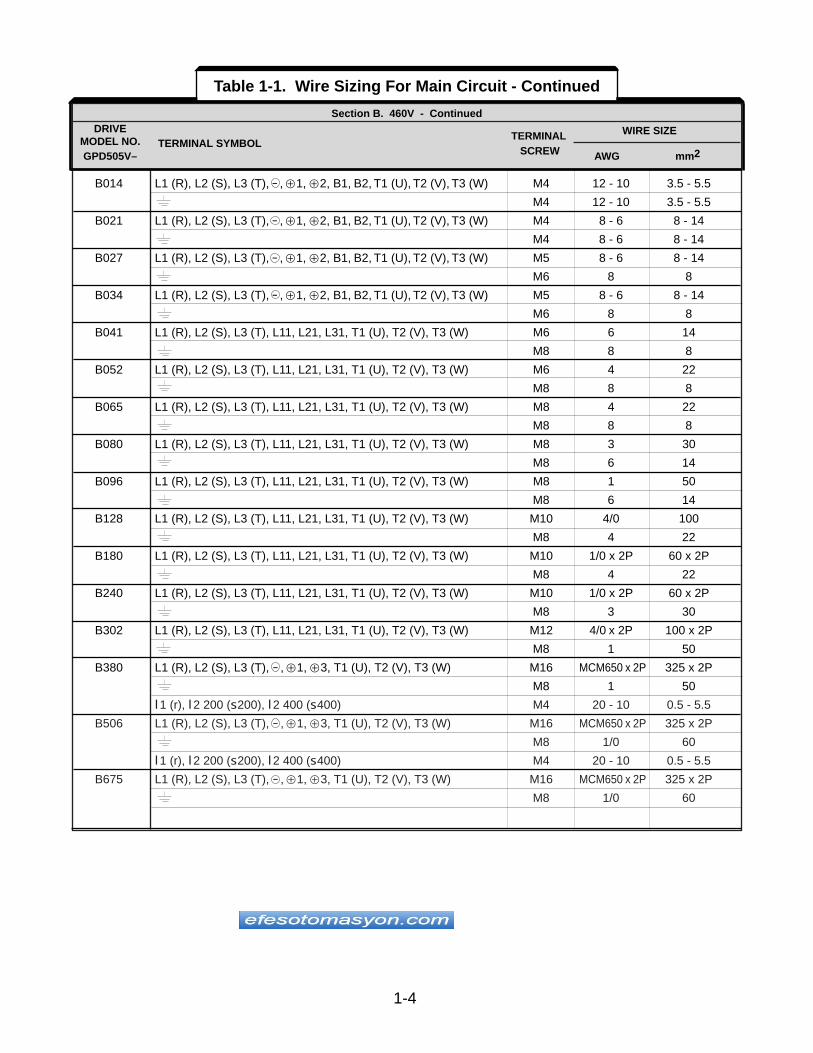
B014 L1 (R), L2 (S), L3 (T), - , Å1, Å2, B1, B2, T1 (U), T2 (V), T3 (W) M4 12 - 10 3.5 - 5.5
M4 12 - 10 3.5 - 5.5
B021 L1 (R), L2 (S), L3 (T), - , Å1, Å2, B1, B2, T1 (U), T2 (V), T3 (W) M4 8 - 6 8 - 14
M4 8 - 6 8 - 14
B027 L1 (R), L2 (S), L3 (T), - , Å1, Å2, B1, B2, T1 (U), T2 (V), T3 (W) M5 8 - 6 8 - 14
M6 8 8
B034 L1 (R), L2 (S), L3 (T), - , Å1, Å2, B1, B2, T1 (U), T2 (V), T3 (W) M5 8 - 6 8 - 14
M6 8 8
B041 L1 (R), L2 (S), L3 (T), L11, L21, L31, T1 (U), T2 (V), T3 (W) M6 6 14
M8 8 8
B052 L1 (R), L2 (S), L3 (T), L11, L21, L31, T1 (U), T2 (V), T3 (W) M6 4 22
M8 8 8
B065 L1 (R), L2 (S), L3 (T), L11, L21, L31, T1 (U), T2 (V), T3 (W) M8 4 22
M8 8 8
B080 L1 (R), L2 (S), L3 (T), L11, L21, L31, T1 (U), T2 (V), T3 (W) M8 3 30
M8 6 14
B096 L1 (R), L2 (S), L3 (T), L11, L21, L31, T1 (U), T2 (V), T3 (W) M8 1 50
M8 6 14
B128 L1 (R), L2 (S), L3 (T), L11, L21, L31, T1 (U), T2 (V), T3 (W) M10 4/0 100
M8 4 22
B180 L1 (R), L2 (S), L3 (T), L11, L21, L31, T1 (U), T2 (V), T3 (W) M10 1/0 x 2P 60 x 2P
M8 4 22
B240 L1 (R), L2 (S), L3 (T), L11, L21, L31, T1 (U), T2 (V), T3 (W) M10 1/0 x 2P 60 x 2P
M8 3 30
B302 L1 (R), L2 (S), L3 (T), L11, L21, L31, T1 (U), T2 (V), T3 (W) M12 4/0 x 2P 100 x 2P
M8 1 50
B380 L1 (R), L2 (S), L3 (T), - , Å1, Å3, T1 (U), T2 (V), T3 (W) M16 MCM650 x 2P 325 x 2P
M8 1 50
l1 (r), l2 200 (s200), l2 400 (s400) M4 20 - 10 0.5 - 5.5
B506 L1 (R), L2 (S), L3 (T), - , Å1, Å3, T1 (U), T2 (V), T3 (W) M16 MCM650 x 2P 325 x 2P
M8 1/0 60
l1 (r), l2 200 (s200), l2 400 (s400) M4 20 - 10 0.5 - 5.5
B675 L1 (R), L2 (S), L3 (T), - , Å1, Å3, T1 (U), T2 (V), T3 (W) M16 MCM650 x 2P 325 x 2P
M8 1/0 60
Section B. 460V - ContinuedDRIVE
TERMINAL WIRE SIZE MODEL NO. TERMINAL SYMBOL GPD505V– SCREW AWG mm2
Table 1-1. Wire Sizing For Main Circuit - Continued
1-5
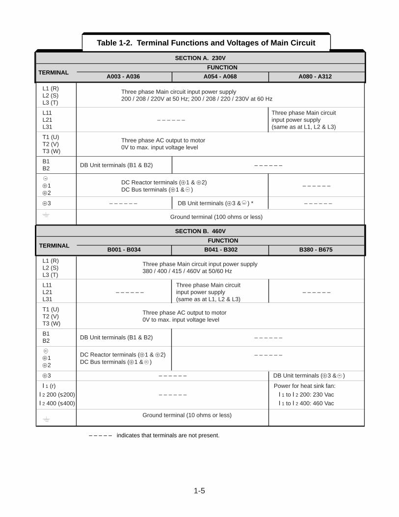
SECTION A. 230V
TERMINAL FUNCTION1 HP 3 TO 40 HP
L1 (R) Three phase Main circuit input power supplyL2 (S) 200 / 208 / 220V at 50 Hz; 200 / 208 / 220 / 230V at 60 HzL3 (T)
L11 Three phase Main circuitL21 – – – – – – input power supplyL31 (same as at L1, L2 & L3)
T1 (U) Three phase AC output to motorT2 (V) 0V to max. input voltage levelT3 (W)
B1B2 DB Unit terminals (B1 & B2) – – – – – –
-Å1 DC Reactor terminals (Å1 & Å2) – – – – – – Å2 DC Bus terminals (Å1 & - )
Å3 – – – – – – DB Unit terminals (Å3 & - ) * – – – – – –
Ground terminal (100 ohms or less)
SECTION B. 460V
TERMINAL FUNCTION 1 TO 60 HP
L1 (R) Three phase Main circuit input power supplyL2 (S) 380 / 400 / 415 / 460V at 50/60 HzL3 (T)
L11 Three phase Main circuitL21 – – – – – – input power supply – – – – – – L31 (same as at L1, L2 & L3)
T1 (U) Three phase AC output to motorT2 (V) 0V to max. input voltage levelT3 (W)
B1B2 DB Unit terminals (B1 & B2) – – – – – –
-Å1 DC Reactor terminals (Å1 & Å2) – – – – – –
Å2 DC Bus terminals (Å1 & - )
Å3 – – – – – – DB Unit terminals (Å3 & - )
l1 (r) Power for heat sink fan:
l2 200 (s200) – – – – – – l1 to l2 200: 230 Vac
l2 400 (s400) l1 to l2 400: 460 Vac
Ground terminal (10 ohms or less)
SECTION A. 230V
FUNCTIONTERMINAL
A003 - A036 A054 - A068 A080 - A312
SECTION B. 460V
FUNCTIONTERMINAL
B001 - B034 B041 - B302 B380 - B675
Table 1-2. Terminal Functions and Voltages of Main Circuit
– – – – – indicates that terminals are not present.
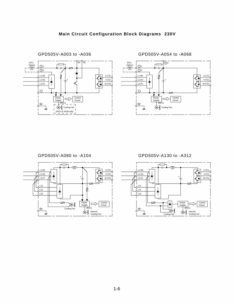
Main Circuit Configuration Block Diagrams 230V
GPD505V-A003 to -A036 GPD505V-A054 to -A068
GPD505V-A080 to -A104 GPD505V-A130 to -A312
1-6
+ 1
+ 2
_
L1 (R)
L2 (S)
L3 (T)
+
PowerSupply
ControlCircuit
Cooling Fan
(A011 to A036 only)
(RCC)
U (T1)
V (T2)
W (T3)
B1 B2 (DCLOption) + 1
+ 2
_
L1 (R)
L2 (S)
L3 (T)
+
PowerSupply
ControlCircuit
Cooling Fan
(RCC)
U (T1)
V (T2)
W (T3)
(DCLOption)
+ 3
L1 (R)
L2 (S)
L3 (T)+
PowerSupply
ControlCircuit
InternalCooling Fan
(RCC)
U (T1)
V (T2)
W (T3)
Cooling Fan
L11
L21
L31
L1 (R)
L2 (S)
L3 (T)+
PowerSupply
ControlCircuit
InternalCooling Fan
(RCC)
U (T1)
V (T2)
W (T3)
Cooling Fan
L11
L21
L31
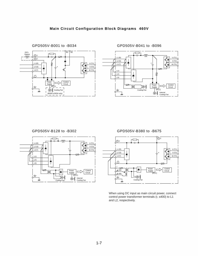
Main Circuit Configuration Block Diagrams 460V
GPD505V-B001 to -B034 GPD505V-B041 to -B096
GPD505V-B128 to -B302 GPD505V-B380 to -B675
1-7
+ 1
+ 2
_
L1 (R)
L2 (S)
L3 (T)
+
PowerSupply
ControlCircuit
Cooling Fan
(B008 to B034 only)
(RCC)
U (T1)
V (T2)
W (T3)
B1 B2 (DCLOption)
L1 (R)
L2 (S)
L3 (T)+
PowerSupply
ControlCircuit
InternalCooling Fan
(RCC)
U (T1)
V (T2)
W (T3)
Cooling Fan
L11
L21
L31
L1 (R)
L2 (S)
L3 (T)+
PowerSupply
ControlCircuit
InternalCooling Fan
(RCC)
U (T1)
V (T2)
W (T3)
Cooling Fan
L11
L21
L31_
L1 (R)
L2 (S)
L3 (T)
+
PowerSupply
ControlCircuit
(RCC)
U (T1)
V (T2)
W (T3)
+ 3
Cooling Fan
r
200
400
+ 1
When using DC input as main circuit power, connectcontrol power transformer terminals (r, s400) to L1and L2, respectively.
1.4 .2 Contro l Ci rcui t
All basic control circuit (signal) interconnections are shown in the appropriate diagram:
• Interconnections for external two-wire control in combination with the Digital Operator are shown in Figure 1-3 (for 230V or 460V rated drives).
• Interconnections for external three-wire control in combination with the Digital Operator are shown in Figure 1-4 (for 230V or 460V rated drives).
Make wiring connections according to Figures 1-1 thru 1-4 and Table 1-3, observing thefollowing :
• Signal Leads : Terminals S1-S6 & SC; FS, FV, FI, FC & G; and AM & AC.
• Control Leads : Terminals M1 & M2 and MA, MB & MC.
• Power Leads : Input Terminals L1 (R), L2 (S), and L3 (T), and Output TerminalsT1 (U), T2 (V), and T3 (W).
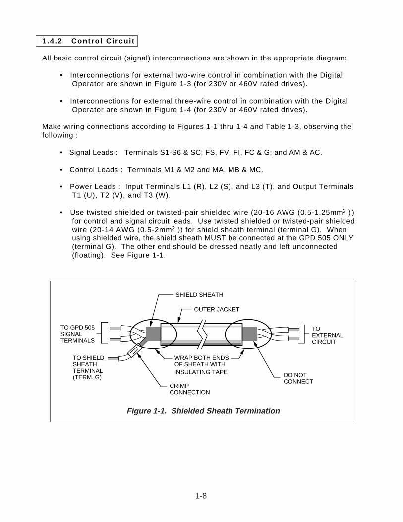
• Use twisted shielded or twisted-pair shielded wire (20-16 AWG (0.5-1.25mm2 ) ) for control and signal circuit leads. Use twisted shielded or twisted-pair shielded wire (20-14 AWG (0.5-2mm2 )) for shield sheath terminal (terminal G). When using shielded wire, the shield sheath MUST be connected at the GPD 505 ONLY (terminal G). The other end should be dressed neatly and left unconnected (floating). See Figure 1-1.
TO GPD 505SIGNALTERMINALS
TO SHIELDSHEATHTERMINAL(TERM. G)
WRAP BOTH ENDSOF SHEATH WITHINSULATING TAPE
CRIMPCONNECTION
SHIELD SHEATH
OUTER JACKET
DO NOTCONNECT
TOEXTERNALCIRCUIT
Figure 1-1. Shielded Sheath Termination
1-8
TERMINAL FUNCTIONS LEVELS
S1 2-WIRE CONTROL: Forward Run / Stop signal Run at closed, stop at open (See NOTE 2)(See NOTE 1)
3-WIRE CONTROL: Run signal Run at closed (See NOTE 2)
S2 2-WIRE CONTROL: Reverse Run / Stop signal Run at closed, stop at open (See NOTES 2 & 3)(See NOTE 1)
3-WIRE CONTROL: Stop signal Stop at open (See NOTES 2 & 3)
S3 External fault input Fault at closed (see NOTES 2 & 3). When the External Fault input is applied, the GPD 505’s Fault relay trips (shutdown) and the motor coasts to a stop. The Digital Operator displays “ EF3 ” failure.
S4 Fault Reset input (external) Fault Reset at closed (see NOTES 2 & 3). The Fault Reset input will reset the Fault relay, if the GPD 505 is in “stopped” condition. Both Forward Run/Stop signal and Reverse Run/Stop signal must be OPEN.
S5 Multi-step Speed Reference 1 Effective when closed (See NOTES 2 & 3)
S6 Multi-step Speed Reference 2 Effective when closed (See NOTES 2 & 3)
SC Sequence control input common Sequence control input 0 Vfor terminals S1-S6.
M1 Multi-function contact output (N.O.). Contact capacity:M2 One of 18 functions are available, by setting 250 Vac at 1A or below
of parameter n041 . 30 Vdc at 1A or below
G Connection for shield sheath of signal leads – – – –
FS Frequency reference power supply +15V (Control power supply for frequency setting:max 20 mA)
FV Frequency reference analog input (voltage); 0 to +10V/100% (20K ohms)auto input – can be changed to manual by See paragraph 5.11.setting of parameter n042 .
FI Frequency reference analog input (current); 4-20mA/100% (250 ohms)can be changed to voltage input by setting of See paragraph 5.11.parameter n043 , and status of jumper J1.
FC Frequency reference analog input common 0 V
MA Multi-function contact output Closed at fault(N.O./N.C.). Contact capacity:
MB One of 18 functions are Open at fault 250 Vac at 1A or belowavailable, by setting of 30 Vdc at 1A or below
MC parameter n040 . Common
TERMINAL FUNCTIONS DESCRIPTION / SIGNAL LEVELS
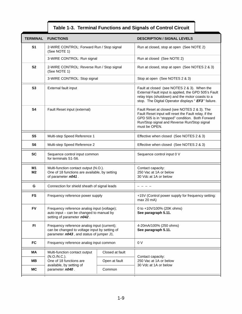
Table 1-3. Terminal Functions and Signals of Control Circuit
1-9
• • •
•• • • • • •
CORRECT CORRECT NOTACCEPTABLE
TERMINAL FUNCTIONS LEVELS
AM Multi-function analog monitor (+) Output current or Type of analog signal (operating parameter) to be output frequency output is selected by setting of parameter n048 .
AC Multi-function analog monitor ( - ) is selectable Monitor output: 0 to +11V; 2 mA maximum
TERMINAL FUNCTIONS DESCRIPTION / SIGNAL LEVELS
NOTES:
1 . When Forward Run and Reverse Run inputs are both closed for more than 500 ms, the Digital Operator displays a blinking “ EF ” alarm code and the motor (if rotating) is decelerated by the GPD 505 to a stop. This stop condition is not stored by the GPD 505 (on Digital Operator, red LEDat STOP key does not light); IF ONE OF THE INPUTS IS OPENED, THE MOTOR WILLIMMEDIATELY START UP AGAIN.
2 . Terminals S1-S6 source +24 Vdc (8mA max.) and operate in a Low = True (ON) configuration whenconnected to terminal SC.
When using relays for input to terminals S1-S6, use relays with highly reliable contacts (for verysmall current) with a capacity of 30 Vdc or more and rated current of 100mA or higher. Whenusing transistor (open collector) input, use transistors with rated voltage of 35 Vdc or more andrated current of 100mA or more.
3 . These terminals are multi-function inputs. The indicated functions are their settings, based on a2-Wire reset. For 3-Wire reset definit ions, and other settings, see descriptions for “Multi-Function Input Terminals”, parameters n 0 3 5 thru n 0 3 9 , in paragraph 5.19.
Table 1-3. Terminal Functions and Signals of Control Circuit - Continued
1-10
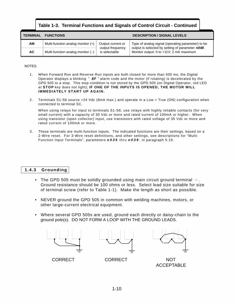
1.4 .3 Grounding
• The GPD 505 must be solidly grounded using main circuit ground terminal .Ground resistance should be 100 ohms or less. Select lead size suitable for size of terminal screw (refer to Table 1-1). Make the length as short as possible.
• NEVER ground the GPD 505 in common with welding machines, motors, or other large-current electrical equipment.
• Where several GPD 505s are used, ground each directly or daisy-chain to the ground pole(s). DO NOT FORM A LOOP WITH THE GROUND LEADS.
1.4.4 Auxil iary Input and Output Power Option Devices
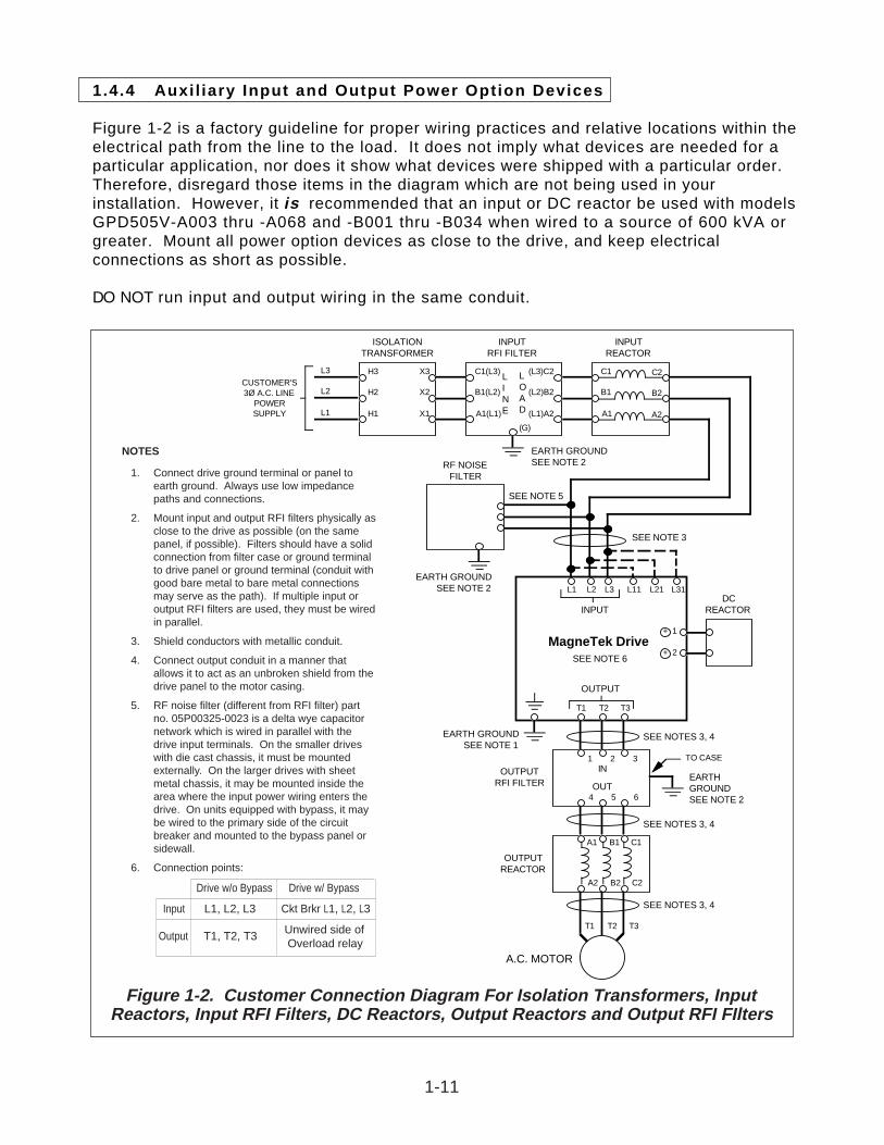
Figure 1-2 is a factory guideline for proper wiring practices and relative locations within theelectrical path from the line to the load. It does not imply what devices are needed for aparticular application, nor does it show what devices were shipped with a particular order.Therefore, disregard those items in the diagram which are not being used in yourinstallation. However, it is recommended that an input or DC reactor be used with modelsGPD505V-A003 thru -A068 and -B001 thru -B034 when wired to a source of 600 kVA orgreater. Mount all power option devices as close to the drive, and keep electricalconnections as short as possible.
DO NOT run input and output wiring in the same conduit.
ISOLATIONTRANSFORMER
INPUTREACTOR
INPUTRFI FILTER
L3
L2
L1
H3
H2
H1
X3
X2
X1
C1
B1
A1
C2
B2
A2
C1(L3)
B1(L2)
A1(L1)
(L3)C2
(L2)B2
(L1)A2
LINE
LOAD
CUSTOMER'S3Ø A.C. LINE
POWERSUPPLY
EARTH GROUNDSEE NOTE 2
(G)
RF NOISEFILTER
SEE NOTE 5
SEE NOTE 3
L3L2L1
T3T2T1
INPUT
OUTPUT
MagneTek Drive
EARTH GROUNDSEE NOTE 1
SEE NOTES 3, 4
OUTPUTREACTOR
OUTPUTRFI FILTER
TO CASE
EARTHGROUNDSEE NOTE 2
SEE NOTES 3, 4
SEE NOTES 3, 4
A.C. MOTOR
1 2 3
4 5 6
IN
OUT
T3T2T1
C1B1A1
C2B2A2
EARTH GROUNDSEE NOTE 2
SEE NOTE 6
DCREACTOR
+ 1
+ 2
L31L21L11
Figure 1-2. Customer Connection Diagram For Isolation Transformers, InputReactors, Input RFI Filters, DC Reactors, Output Reactors and Output RFI FIlters
1-11
NOTES
1. Connect drive ground terminal or panel toearth ground. Always use low impedancepaths and connections.
2. Mount input and output RFI filters physically asclose to the drive as possible (on the samepanel, if possible). Filters should have a solidconnection from filter case or ground terminalto drive panel or ground terminal (conduit withgood bare metal to bare metal connectionsmay serve as the path). If multiple input oroutput RFI filters are used, they must be wiredin parallel.
3. Shield conductors with metallic conduit.
4. Connect output conduit in a manner thatallows it to act as an unbroken shield from thedrive panel to the motor casing.
5. RF noise filter (different from RFI filter) partno. 05P00325-0023 is a delta wye capacitornetwork which is wired in parallel with thedrive input terminals. On the smaller driveswith die cast chassis, it must be mountedexternally. On the larger drives with sheetmetal chassis, it may be mounted inside thearea where the input power wiring enters thedrive. On units equipped with bypass, it maybe wired to the primary side of the circuitbreaker and mounted to the bypass panel orsidewall.
6. Connection points:
Drive w/o Bypass Drive w/ Bypass
Input L1, L2, L3 Ckt Brkr L1, L2, L3
Output T1, T2, T3 Unwired side ofOverload relay
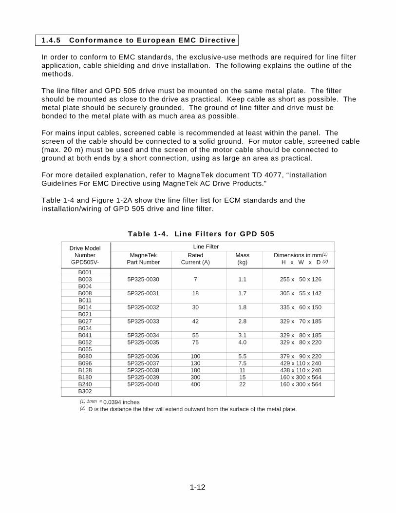
1.4.5 Conformance to European EMC Directive
In order to conform to EMC standards, the exclusive-use methods are required for line filterapplication, cable shielding and drive installation. The following explains the outline of themethods.
The line filter and GPD 505 drive must be mounted on the same metal plate. The filtershould be mounted as close to the drive as practical. Keep cable as short as possible. Themetal plate should be securely grounded. The ground of line filter and drive must bebonded to the metal plate with as much area as possible.
For mains input cables, screened cable is recommended at least within the panel. Thescreen of the cable should be connected to a solid ground. For motor cable, screened cable(max. 20 m) must be used and the screen of the motor cable should be connected toground at both ends by a short connection, using as large an area as practical.
For more detailed explanation, refer to MagneTek document TD 4077, “InstallationGuidelines For EMC Directive using MagneTek AC Drive Products.”
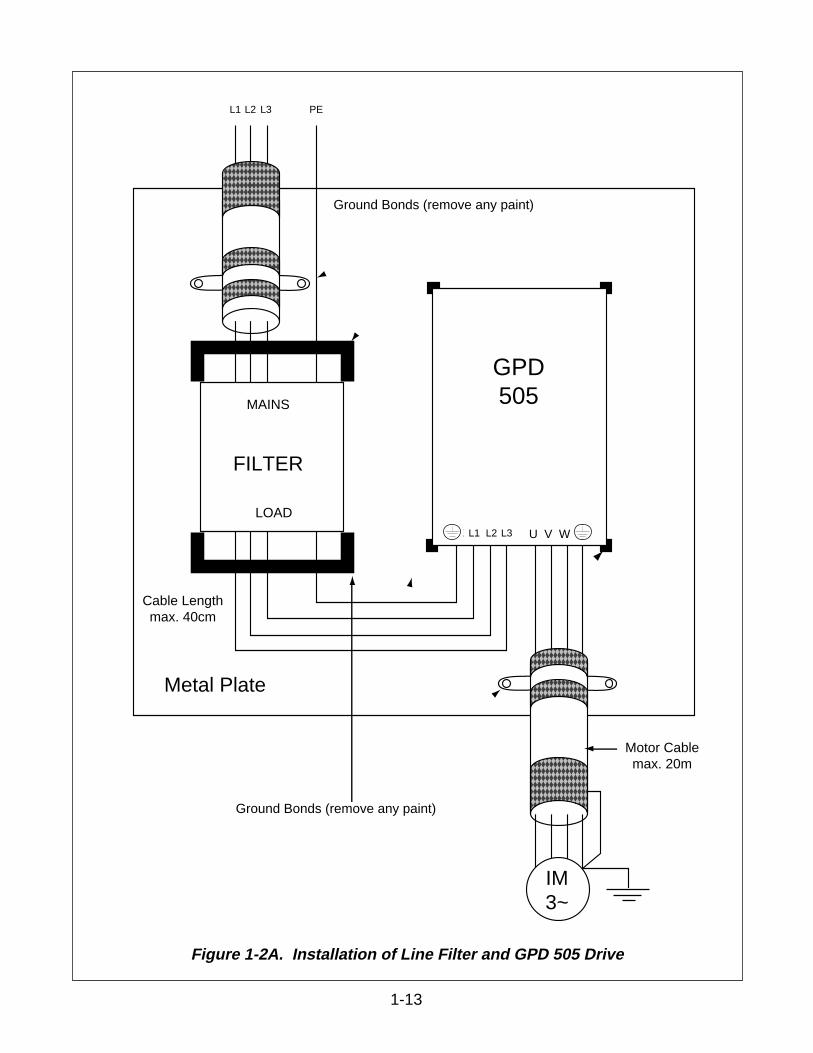
Table 1-4 and Figure 1-2A show the line filter list for ECM standards and theinstallation/wiring of GPD 505 drive and line filter.
Table 1-4 . L ine Fi l ters for GPD 505
1-12
Drive Model Line Filter
Number MagneTek Rated Mass Dimensions in mm(1)
GPD505V- Part Number Current (A) (kg) H x W x D (2)
B001B003 5P325-0030 7 1.1 255 x 50 x 126B004B008 5P325-0031 18 1.7 305 x 55 x 142B011B014 5P325-0032 30 1.8 335 x 60 x 150B021B027 5P325-0033 42 2.8 329 x 70 x 185B034B041 5P325-0034 55 3.1 329 x 80 x 185B052 5P325-0035 75 4.0 329 x 80 x 220B065B080 5P325-0036 100 5.5 379 x 90 x 220B096 5P325-0037 130 7.5 429 x 110 x 240B128 5P325-0038 180 11 438 x 110 x 240B180 5P325-0039 300 15 160 x 300 x 564B240 5P325-0040 400 22 160 x 300 x 564B302
(1) 1mm = 0.0394 inches(2) D is the distance the filter will extend outward from the surface of the metal plate.
1-13
yz|yz|yz|
yz|
yz|yzMotor Cablemax. 20m
Cable Lengthmax. 40cm
L2 PEL1 L3
MAINS
LOAD
FILTER
INVERTER
L2 PEL1 L3L1 L3PE L2
Ground Bands (remove any paint)
Ground Bands (remove any paint)
Metal Plate
IM3~
U V W
Ground Bonds (remove any paint)
Ground Bonds (remove any paint)
GPD505
Figure 1-2A. Installation of Line Filter and GPD 505 Drive
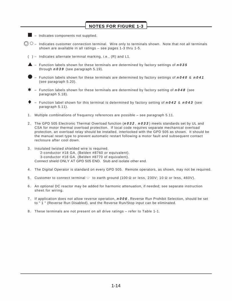
NOTES FOR FIGURE 1-3
– Indicates components not supplied.
– Indicates customer connection terminal. Wire only to terminals shown. Note that not all terminals shown are available in all ratings – see pages 1-3 thru 1-5.
( ) – Indicates alternate terminal marking, i.e., (R) and L1.
– Function labels shown for these terminals are determined by factory settings of n 0 3 5through n 0 3 9 (see paragraph 5.19).
– Function labels shown for these terminals are determined by factory settings of n 0 4 0 & n 0 4 1(see paragraph 5.20).
– Function labels shown for these terminals are determined by factory setting of n 0 4 8 (see paragraph 5.18).
¨ – Function label shown for this terminal is determined by factory setting of n 0 4 2 & n 0 4 3 (see paragraph 5.11).
1 . Multiple combinations of frequency references are possible – see paragraph 5.11.
2 . The GPD 505 Electronic Thermal Overload function (n 0 3 2 , n 0 3 3 ) meets standards set by UL andCSA for motor thermal overload protection. If local code requires separate mechanical overloadprotection, an overload relay should be installed, interlocked with the GPD 505 as shown. It should bethe manual reset type to prevent automatic restart following a motor fault and subsequent contactreclosure after cool down.
3 . Insulated twisted shielded wire is required. 2-conductor #18 GA. (Belden #8760 or equivalent).3-conductor #18 GA. (Belden #8770 of equivalent).
Connect shield ONLY AT GPD 505 END. Stub and isolate other end.
4 . The Digital Operator is standard on every GPD 505. Remote operators, as shown, may not be required.
5 . Customer to connect terminal to earth ground (100 ½ or less, 230V; 10 ½ or less, 460V).
6 . An optional DC reactor may be added for harmonic attenuation, if needed; see separate instructionsheet for wir ing.
7 . If application does not allow reverse operation, n 0 0 6 , Reverse Run Prohibit Selection, should be setto " 1 " (Reverse Run Disabled), and the Reverse Run/Stop input can be eliminated.
8 . These terminals are not present on all drive ratings – refer to Table 1-1.
1-14
1-15
L1 ( R )
L2 ( S )
L3 ( T )
Frequency SettingPower Supply (+15V, 20mA)
Freq. Ref.0 to 10V (20K½)
M1
M2
B2B1
ACMOTOR
U (T1)
V (T2)
W (T3)
MCCB
GPD 505
L1
L2
L3
S1
ForwardRun/Stop
SequenceCommon
IsolatedFrequencyReference
3-PhasePower Supply
Multi-functionOutput Contact250VAC, 1A or less30VDC, 1A or less
Shield
Analog Monitor
ReverseRun/Stop
S2
S3
S4
S5
FaultReset
ExternalFault
Multi-stepSpeed Ref. 1
SC
FC
FS
FV
AM
ACFM
Multi-function AnalogOutput 0 to +10V (2mA max.)
Output Frequency(Factory Setting)
Multi-functionContact Inputs
MA
MB
MC
RUNNING
FAULT
Forward Runwhen CLOSED(See Note 7)
(See Notes 1 & 4)
Ground (See Note 5)
(See Note 3)
1RHManualSpeed
2K½
4-20mA
1OL (See Note 2)
–+
FactoryDefaultsper2-WireInitialization
Multi-stepSpeed Ref. 2 S6
G
G
+ +– 1 2
Freq. Ref.4 to 20mA (250½)(0 to 10V input available)
FI
Multi-functionOutput Contact250VAC, 1A or less30VDC, 1A or less
(SeeNote 2)
1OL
380V
460V, GPD505V-B041thru -B096
Factory Set For 460V
400/415V 440V 460V
Voltage Selector
0-10VDC
(See Note 4)
+ 3
L11
L21
L31
DC Reactor(See Note 6)
*
Freq. Ref. Common–+
(See Note 8)
(See Note 8)
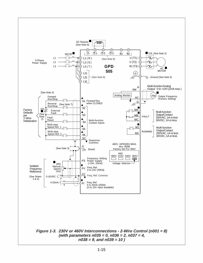
Figure 1-3. 230V or 460V Interconnections - 2-Wire Control (n001 = 8)(with parameters n035 = 0, n036 = 2, n037 = 4,
n038 = 9, and n039 = 10 )
NOTES FOR FIGURE 1-4
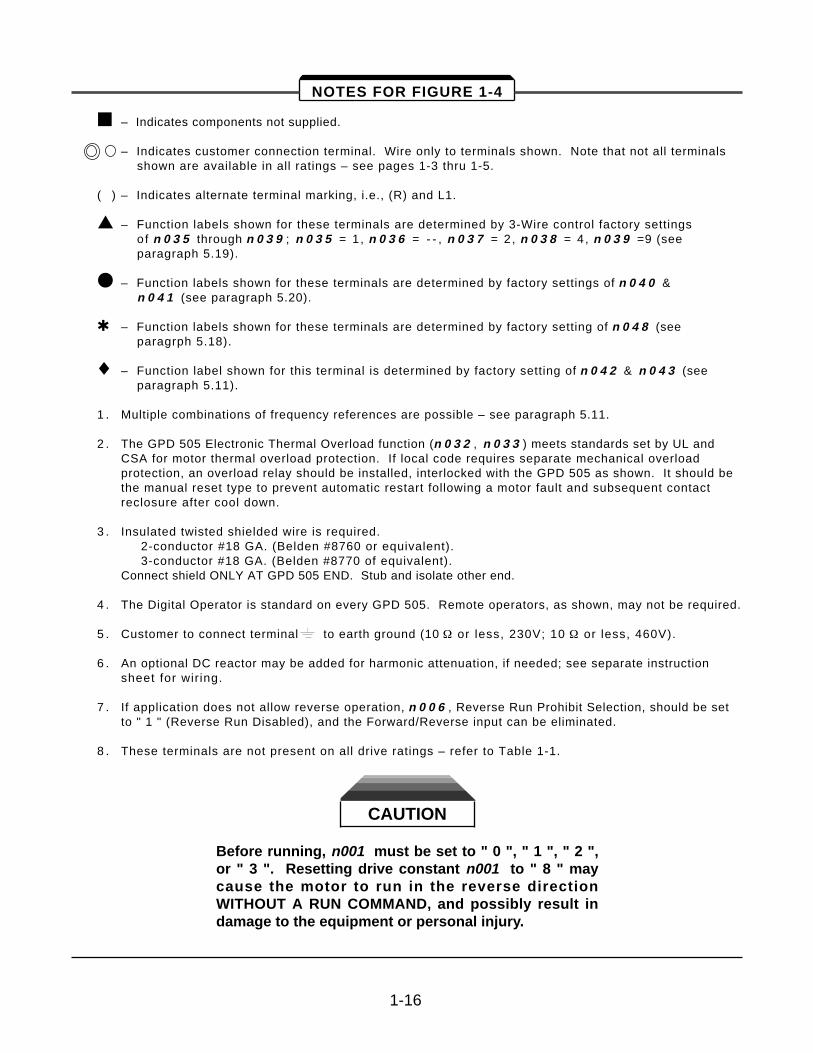
– Indicates components not supplied.
– Indicates customer connection terminal. Wire only to terminals shown. Note that not all terminals shown are available in all ratings – see pages 1-3 thru 1-5.
( ) – Indicates alternate terminal marking, i.e., (R) and L1.
– Function labels shown for these terminals are determined by 3-Wire control factory settings of n 0 3 5 through n 0 3 9 ; n 0 3 5 = 1 , n 0 3 6 = - - , n 0 3 7 = 2 , n 0 3 8 = 4 , n 0 3 9 =9 (see paragraph 5.19).
– Function labels shown for these terminals are determined by factory settings of n 0 4 0 & n 0 4 1 (see paragraph 5.20).
– Function labels shown for these terminals are determined by factory setting of n 0 4 8 (see paragrph 5.18).
¨ – Function label shown for this terminal is determined by factory setting of n 0 4 2 & n 0 4 3 (see paragraph 5.11).
1 . Multiple combinations of frequency references are possible – see paragraph 5.11.
2 . The GPD 505 Electronic Thermal Overload function (n 0 3 2 , n 0 3 3 ) meets standards set by UL andCSA for motor thermal overload protection. If local code requires separate mechanical overloadprotection, an overload relay should be installed, interlocked with the GPD 505 as shown. It should bethe manual reset type to prevent automatic restart following a motor fault and subsequent contactreclosure after cool down.
3 . Insulated twisted shielded wire is required. 2-conductor #18 GA. (Belden #8760 or equivalent).3-conductor #18 GA. (Belden #8770 of equivalent).
Connect shield ONLY AT GPD 505 END. Stub and isolate other end.
4 . The Digital Operator is standard on every GPD 505. Remote operators, as shown, may not be required.
5 . Customer to connect terminal to earth ground (10 ½ or less, 230V; 10 ½ or less, 460V).
6 . An optional DC reactor may be added for harmonic attenuation, if needed; see separate instructionsheet for wir ing.
7 . If application does not allow reverse operation, n 0 0 6 , Reverse Run Prohibit Selection, should be setto " 1 " (Reverse Run Disabled), and the Forward/Reverse input can be eliminated.
8 . These terminals are not present on all drive ratings – refer to Table 1-1.
CAUTION
Before running, n001 must be set to " 0 ", " 1 ", " 2 ",or " 3 ". Resetting drive constant n001 to " 8 " maycause the motor to run in the reverse directionWITHOUT A RUN COMMAND, and possibly result indamage to the equipment or personal injury.
1-16
1-17
L1 ( R )
L2 ( S )
L3 ( T )
Frequency SettingPower Supply (+15V, 20mA)
Freq. Ref.0 to 10V (20K½)
M1
M2
B2B1
ACMOTOR
U (T1)
V (T2)
W (T3)
MCCB
GPD 505
L1
L2
L3
S1Run
SequenceCommon
3-PhasePower Supply
Multi-functionOutput Contact250VAC, 1A or less30VDC, 1A or less
Shield
Analog Monitor
StopS2
S3
S4
S5
Multi-stepSpeed Ref. 1
FaultReset
Multi-stepSpeed Ref. 2
SC
FC
FS
FV
AM
ACFM
Multi-function AnalogOutput 0 to +10V (2mA max.)
Output Frequency(Factory Setting)
Multi-functionContact Inputs
MA
MB
MC
RUNNING
FAULT
Forward Runwhen CLOSED
(See Note 7)
Ground (See Note 5)
(See Note 3)
1OL (See Note 2)
FactoryDefaultsper3-WireInitialization
Forward/Reverse
S6
G
G
+ +– 1 2
Freq. Ref.4 to 20mA (250½)(0 to 10V input available)
FI
Multi-functionOutput Contact250VAC, 1A or less30VDC, 1A or less
(SeeNote 2)
1OL
380V
460V, GPD505V-B041thru -B096
Factory Set For 460V
400/415V 440V 460V
Voltage Selector
(See Note 4)
+ 3
L11
L21
L31
DC Reactor(See Note 6)
*
Freq. Ref. Common
IsolatedFrequencyReference
(See Notes 1 & 4)
1RHManualSpeed
2K½
4-20mA –+
0-10VDC –+
(See Note 8)
(See Note 8)
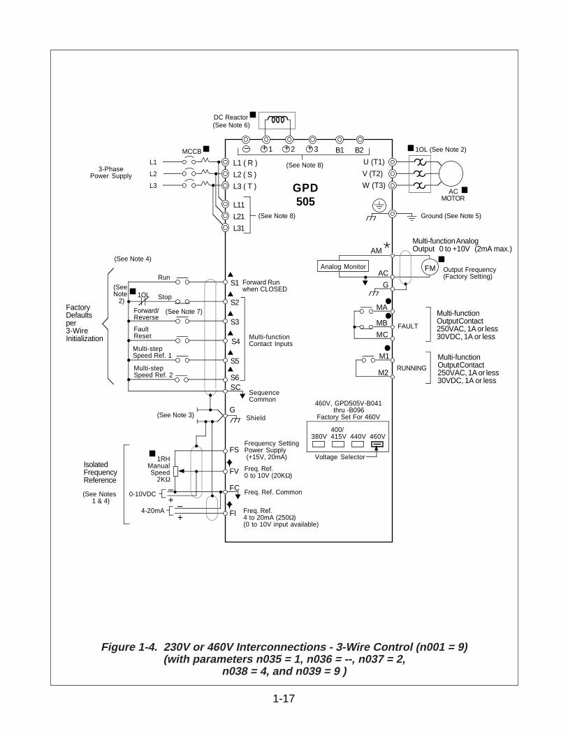
Figure 1-4. 230V or 460V Interconnections - 3-Wire Control (n001 = 9)(with parameters n035 = 1, n036 = --, n037 = 2,
n038 = 4, and n039 = 9 )
• Verify wires are properly connected and no erroneous grounds exist.
• Remove all debris from the GPD 505 enclosure. Check for loose wire clippings, metalshavings, etc.
• Verify all mechanical connections inside the GPD 505 are tight.
• Verify motor is not connected to load.
• Apply input power only after the front cover is in place. DO NOT remove the front coveror Digital Operator while input power is on.
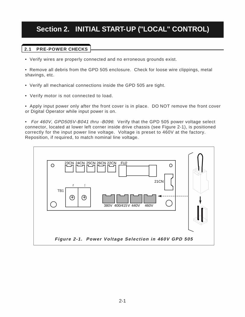
• For 460V, GPD505V-B041 thru -B096: Verify that the GPD 505 power voltage selectconnector, located at lower left corner inside drive chassis (see Figure 2-1), is positionedcorrectly for the input power line voltage. Voltage is preset to 460V at the factory.Reposition, if required, to match nominal line voltage.
2-1
23CN 24CN 25CN 26CN 22CN FU2
21CNsr
TB1
+ +380V 400/415V 440V 460V •
• •
•
Figure 2-1 . Power Vol tage Select ion in 460V GPD 505
2.1 PRE-POWER CHECKS
Section 2. INITIAL START-UP ("LOCAL" CONTROL)
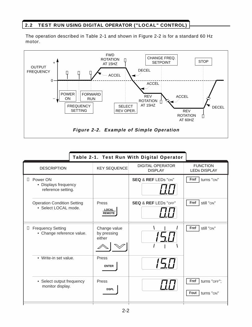
The operation described in Table 2-1 and shown in Figure 2-2 is for a standard 60 Hzmotor.
DESCRIPTION KEY SEQUENCEDIGITAL OPERATOR FUNCTION
DISPLAY LEDs DISPLAY
➀ Power ON SEQ & REF LEDs "ON" turns "ON"• Displays frequency
reference setting.
Operation Condition Setting Press SEQ & REF LEDs "OFF" still "ON"• Select LOCAL mode.
➁ Frequency Setting Change value still "ON"• Change reference value. by pressing
either
• Write-in set value. Press
• Select output frequency Press turns "OFF";monitor display.
turns "ON"Fout
Fref
Fref
Fref
Fref
Table 2-1. Test Run With Digi tal Operator
2-2
+OUTPUT
FREQUENCY
0
–
SELECTREV OPER.
CHANGE FREQ.SETPOINT
POWERON
FREQUENCYSETTING
FORWARDRUN
STOP
FWDROTATIONAT 15HZ
REVROTATIONAT 60HZ
REVROTATIONAT 15HZ
ACCEL
ACCEL
ACCEL
DECEL
DECEL
Figure 2-2. Example of Simple Operation
2.2 TEST RUN USING DIGITAL OPERATOR ("LOCAL" CONTROL)
➀ ➁ ➂
➃
➄
➅
LOCALREMOTE
ENTER
DSPL
\ | /
/ | \
DESCRIPTION KEY SEQUENCEDIGITAL OPERATOR FUNCTION
DISPLAY LEDs DISPLAY
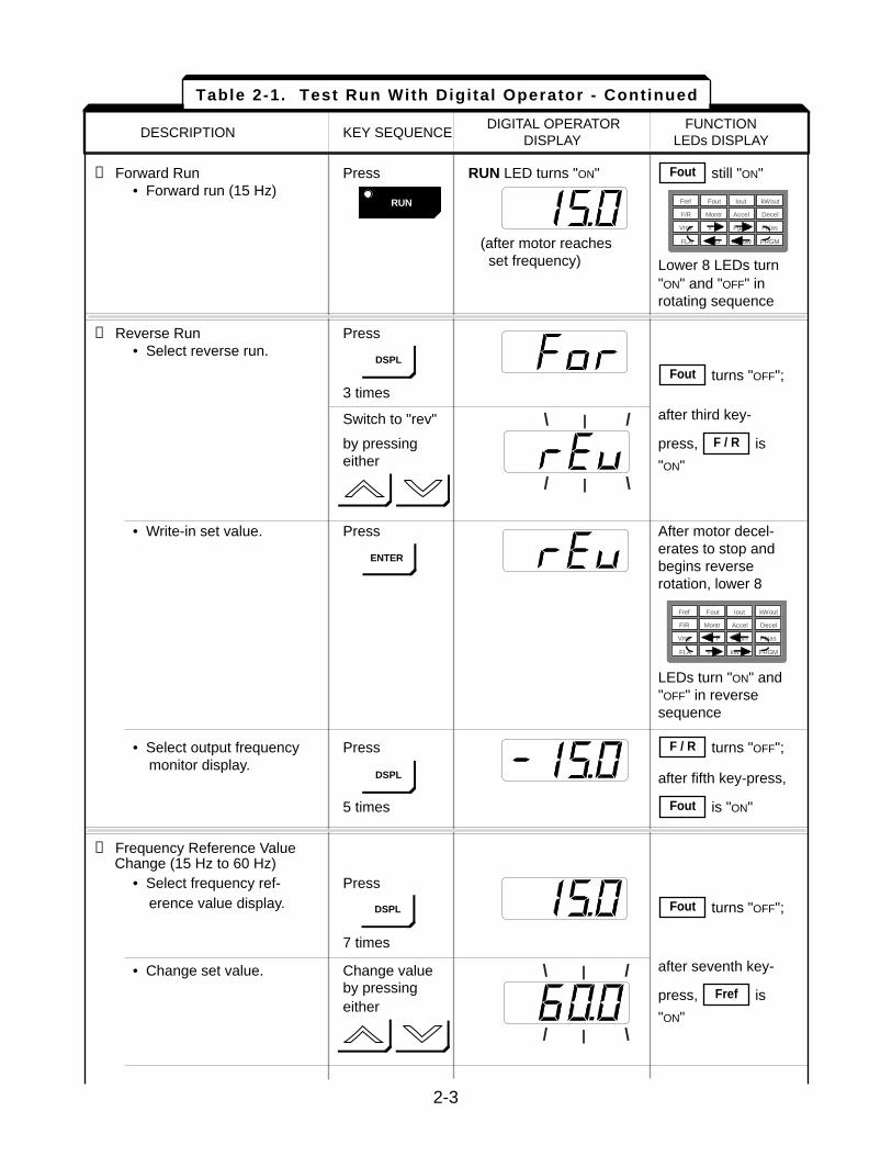
➂ Forward Run Press RUN LED turns "ON" still "ON"• Forward run (15 Hz)
(after motor reaches set frequency) Lower 8 LEDs turn
"ON" and "OFF" in rotating sequence
➃ Reverse Run Press• Select reverse run.
turns "OFF";3 times
Switch to "rev" after third key-
by pressing press, is either "ON"
• Write-in set value. Press After motor decel-erates to stop and begins reverse rotation, lower 8
LEDs turn "ON" and "OFF" in reverse sequence
• Select output frequency Press turns "OFF";monitor display.
after fifth key-press,
5 times is "ON"
➄ Frequency Reference ValueChange (15 Hz to 60 Hz)
• Select frequency ref- Presserence value display. turns "OFF";
7 times
• Change set value. Change value after seventh key-
by pressing press, is either
"ON"
Fref
Fout
Fout
F / R
F / R
Fout
Fout
Table 2-1. Test Run With Digital Operator - Continued
2-3
RUN
FLA
Fref Fout Iout
AccelF/R
Vmtr V / F
PID
kWout
DecelMontr
PRGM
FbiasFgain
kWsav
DSPL
ENTER
FLA
Fref Fout Iout
AccelF/R
Vmtr V / F
PID
kWout
DecelMontr
PRGM
FbiasFgain
kWsav
DSPL
DSPL
\ | /
/ | \
\ | /
/ | \
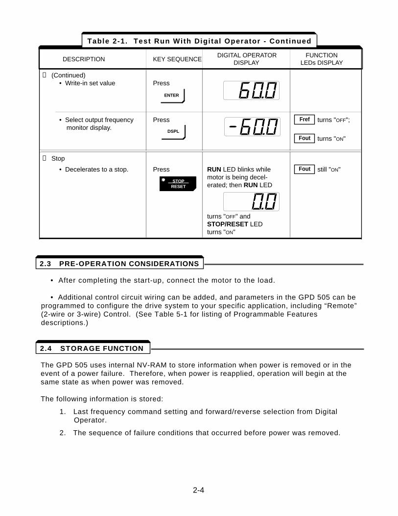
• After completing the start-up, connect the motor to the load.
• Additional control circuit wiring can be added, and parameters in the GPD 505 can beprogrammed to configure the drive system to your specific application, including “Remote”(2-wire or 3-wire) Control. (See Table 5-1 for listing of Programmable Featuresdescriptions.)
The GPD 505 uses internal NV-RAM to store information when power is removed or in theevent of a power failure. Therefore, when power is reapplied, operation will begin at thesame state as when power was removed.
The following information is stored:
1. Last frequency command setting and forward/reverse selection from DigitalOperator.
2. The sequence of failure conditions that occurred before power was removed.
2-4
DESCRIPTION KEY SEQUENCEDIGITAL OPERATOR FUNCTION
DISPLAY LEDs DISPLAY
➄ (Continued)• Write-in set value Press
• Select output frequency Press turns "OFF";monitor display.
turns "ON"
➅ Stop
• Decelerates to a stop. Press RUN LED blinks while still "ON"motor is being decel-erated; then RUN LED
turns "OFF" and STOP/RESET LED turns "ON"
Fout
Fout
Fref
Table 2-1. Test Run With Digital Operator - Continued
ENTER
DSPL
STOPRESET
2.3 PRE-OPERATION CONSIDERATIONS
2.4 STORAGE FUNCTION
After completing the start-up, and programming of constants, turn off the AC main circuitpower. Make additional wiring connections required for the external control functionsselected by the constant programming. Connect the driven machine to the motor. Verifythat the driven machine is in running condition, and that no dangerous conditions existaround the drive system.
OPERATING PRECAUTIONS
• Before applying a RUN command to the GPD 505, verify that the motor isstopped. If the application requires the capability of restarting a coasting motor,parameter n 0 6 6 must be set to give DC Braking Time at Start.
• The motor cooling effect is reduced during low-speed running. The torque needsto be reduced in accordance with the frequency. For the reduction ratio, refer tothe motor catalog or technical sheet.
• NEVER use a motor whose full-load amps exceeds the GPD 505 rating.
• When two or more motors are operated by one GPD 505, verify that the totalmotor current DOES NOT EXCEED the GPD 505 rating.
• When starting and stopping the motor, use the operation signals (RUN/STOP,FWD/REV), NOT the magnetic contactor on the power supply side.
Run the motor under load with control by the Digital Operator using the same procedure asfor the Test Run (Table 2-1). If the Digital Operator is used in combination with externalcommands or external commands only are used, the procedure must be alteredaccordingly.
For preset starting (one-touch operation after setting the frequency), perform thefollowing:
1 . Set the frequency and press RUN. Motor accelerates, at the rate corresponding tothe preset accel time, to the preset frequency. The accel time is set too shortrelative to the load if the RPM of the accelerating motor does not increase smoothly(stall prevention during acceleration is functioning) or if a fault indication isdisplayed on the Digital Operator.
2 . Press STOP. Motor decelerates, at the rate corresponding to the preset decel time,to a stop. The decel time is set too short relative to the load if the RPM of thedecelerating motor does not decrease smoothly (stall prevention duringdeceleration is functioning) or if a fault indication is displayed on the DigitalOperator.
3-1
Section 3. OPERATION AT LOAD
All functions of the GPD 505 are accessed using the Digital Operator. In addition tocontrolling motor operation, the operator can enter information into the GPD 505 memoryto configure the GPD 505 to the application, either by using the Function LEDs, or byentering the Program (PRGM) mode.
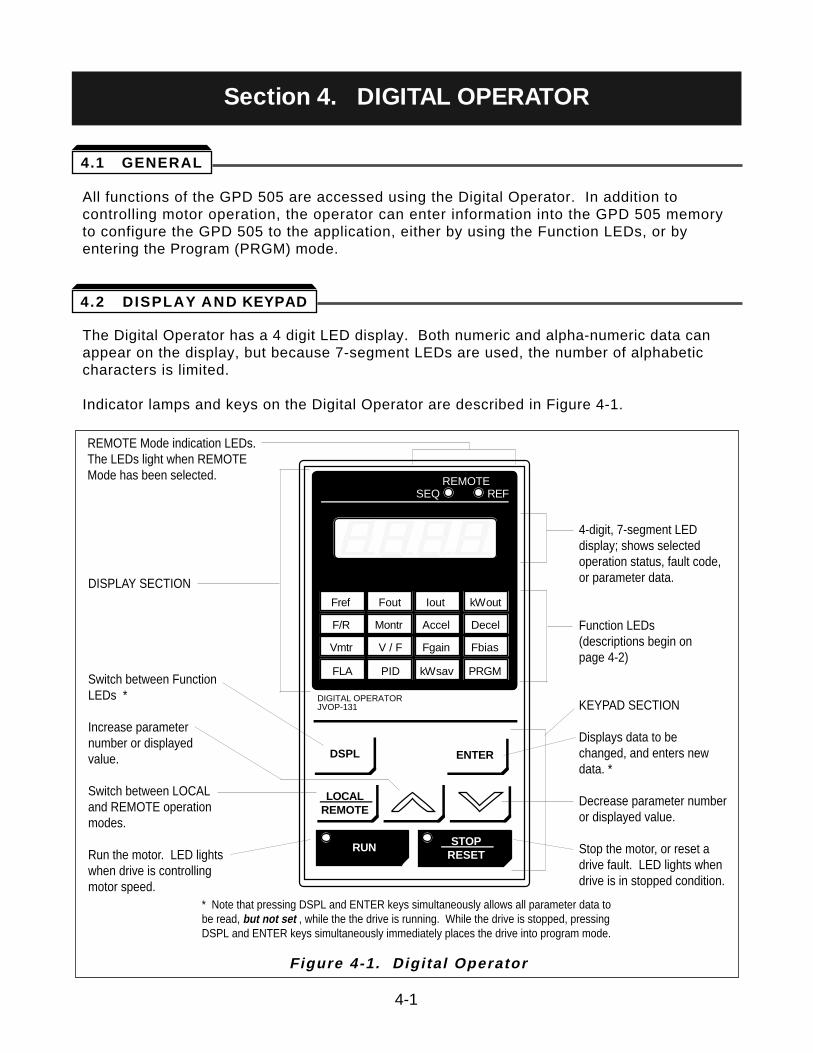
The Digital Operator has a 4 digit LED display. Both numeric and alpha-numeric data canappear on the display, but because 7-segment LEDs are used, the number of alphabeticcharacters is limited.
Indicator lamps and keys on the Digital Operator are described in Figure 4-1.
Figure 4-1. Digi tal Operator
4-1
DSPL ENTER
FLA
Fref Fout Iout
AccelF/R
Vmtr V / F
PID
DIGITAL OPERATORJVOP-131
REMOTESEQ REF
kWout
DecelMontr
PRGM
FbiasFgain
kWsav
RUN STOPRESET
LOCALREMOTE
4.1 GENERAL
4.2 DISPLAY AND KEYPAD
Section 4. DIGITAL OPERATOR
DISPLAY SECTION
Switch between FunctionLEDs *
Increase parameternumber or displayedvalue.
Switch between LOCALand REMOTE operationmodes.
Run the motor. LED lightswhen drive is controllingmotor speed.
* Note that pressing DSPL and ENTER keys simultaneously allows all parameter data tobe read, but not set , while the the drive is running. While the drive is stopped, pressingDSPL and ENTER keys simultaneously immediately places the drive into program mode.
4-digit, 7-segment LEDdisplay; shows selectedoperation status, fault code,or parameter data.
Function LEDs(descriptions begin on page 4-2)
KEYPAD SECTION
Displays data to bechanged, and enters newdata. *
Decrease parameter numberor displayed value.
Stop the motor, or reset adrive fault. LED lights whendrive is in stopped condition.
REMOTE Mode indication LEDs.The LEDs light when REMOTE Mode has been selected.
4.2.1 Descript ion of Function LEDs
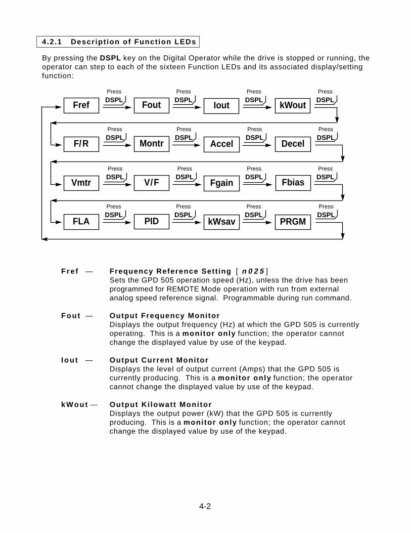
By pressing the DSPL key on the Digital Operator while the drive is stopped or running, theoperator can step to each of the sixteen Function LEDs and its associated display/settingfunction:
Fref — Frequency Reference Setting [ n 0 2 5 ] Sets the GPD 505 operation speed (Hz), unless the drive has been programmed for REMOTE Mode operation with run from external analog speed reference signal. Programmable during run command.
Fout — Output Frequency MonitorDisplays the output frequency (Hz) at which the GPD 505 is currently operating. This is a monitor only function; the operator cannot change the displayed value by use of the keypad.
I ou t — Output Current MonitorDisplays the level of output current (Amps) that the GPD 505 is currently producing. This is a monitor only function; the operator cannot change the displayed value by use of the keypad.
kWout — Output Ki lowatt MonitorDisplays the output power (kW) that the GPD 505 is currently producing. This is a monitor only function; the operator cannot change the displayed value by use of the keypad.
4-2
Fref Fout kWout
F/R
Vmtr
Montr
V/F
Decel
Fbias
FLA PID PRGM
Press
DSPL
Press
DSPL
Press
DSPL
Press
DSPL
Press
DSPL
Press
DSPL
Press
DSPL
Press
DSPL
Iout
Accel
Fgain
kWsav
Press
DSPL
Press
DSPL
Press
DSPL
Press
DSPL
Press
DSPL
Press
DSPL
Press
DSPL
Press
DSPL
F / R — FWD/REV Run SelectionSets the rotation direction of the motor when a Run command is given by the Digital Operator keypad. Display of For = forward run, rEu = reverse run. Use of this Function LED toggles between these two presets; the operator cannot enter a value.
Montr — Monitor SelectionPressing ENTER allows access to the various Monitor parameters, U - 0 1 through U - 1 3 . These are monitor only functions; the operator cannot change the displayed value. See paragraph 4.4 for list of Monitor parameters. Programmable during run command.
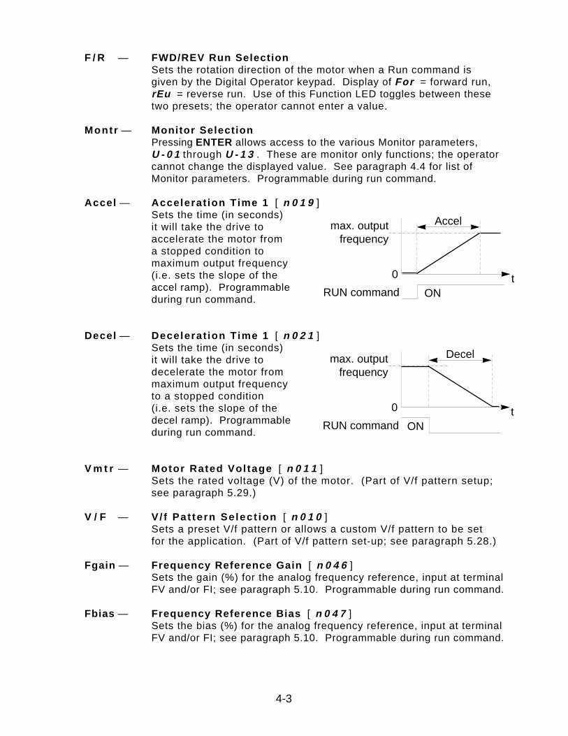
Accel — Accelerat ion Time 1 [ n 0 1 9 ] Sets the time (in seconds) it will take the drive to accelerate the motor from a stopped condition to maximum output frequency (i.e. sets the slope of the accel ramp). Programmable during run command.
Decel — Decelerat ion Time 1 [ n 0 2 1 ] Sets the time (in seconds) it will take the drive to decelerate the motor from maximum output frequency to a stopped condition (i.e. sets the slope of the decel ramp). Programmable during run command.
V m t r — Motor Rated Voltage [ n 0 1 1 ] Sets the rated voltage (V) of the motor. (Part of V/f pattern setup;see paragraph 5.29.)
V / F — V/ f Pat tern Se lect ion [ n 0 1 0 ] Sets a preset V/f pattern or allows a custom V/f pattern to be set for the application. (Part of V/f pattern set-up; see paragraph 5.28.)
Fgain — Frequency Reference Gain [ n 0 4 6 ] Sets the gain (%) for the analog frequency reference, input at terminal FV and/or FI; see paragraph 5.10. Programmable during run command.
Fbias — Frequency Reference Bias [ n 0 4 7 ] Sets the bias (%) for the analog frequency reference, input at terminal FV and/or FI; see paragraph 5.10. Programmable during run command.
4-3
t0
ONRUN command
Accelmax. outputfrequency
t0
ONRUN command
Decelmax. outputfrequency
FLA — Motor Rated Current [ n 0 3 2 ] Sets the Amps used for detecting motor overload. This is normally set to the motor rated current value (nameplate full-load amps). When set to " 0.0 ", motor overload protection is disabled. The factory settings are listed in Appendix 1.
PID — PID Selection [ n 0 8 4 ] Setting data to " 0 " (factory setting) disables the PID function. Setting to " 1 " enables PID; setting to " 2 " enables the “Feed Forward” function; setting to “ 3 “ enables the “Inverted PID” function. See “PID Control”, paragraph 5.22.
kWsav — Energy Saving Selection [ n 0 9 5 ] Setting data to " 0 " (factory setting) disables the energy saving function; and setting to " 1 " enables this function. See “Energy Saving Control”, paragraph 5.9.
PRGM — Parameter ProgrammingSelects or reads data using parameter number (nXXX ). Data is displayed by pressing the ENTER key, and can be changed by pressing the “up arrow” or “down arrow” keys. Any changes can be saved by again pressing the ENTER key. Pressing the DSPL key exits the Programming mode.
4-4
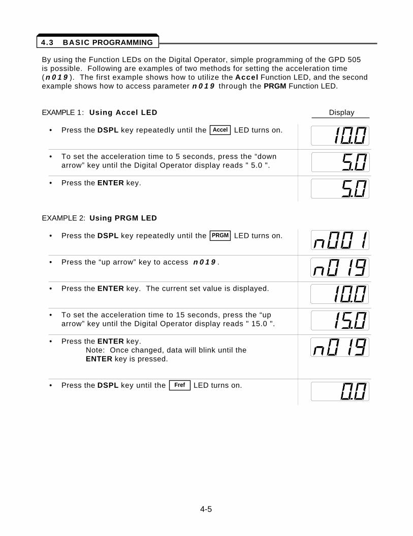
By using the Function LEDs on the Digital Operator, simple programming of the GPD 505 is possible. Following are examples of two methods for setting the acceleration time(n 0 1 9 ). The first example shows how to utilize the Accel Function LED, and the secondexample shows how to access parameter n 0 1 9 through the PRGM Function LED.
EXAMPLE 1: Using Accel LED Display
• Press the DSPL key repeatedly until the LED turns on.
• To set the acceleration time to 5 seconds, press the “down arrow” key until the Digital Operator display reads " 5.0 ".
• Press the ENTER key.
EXAMPLE 2: Using PRGM LED
• Press the DSPL key repeatedly until the LED turns on.
• Press the “up arrow” key to access n 0 1 9 .
• Press the ENTER key. The current set value is displayed.
• To set the acceleration time to 15 seconds, press the “up arrow” key until the Digital Operator display reads " 15.0 ".
• Press the ENTER key.Note: Once changed, data will blink until the ENTER key is pressed.
• Press the DSPL key until the LED turns on.Fref
PRGM
Accel
4-5
4.3 BASIC PROGRAMMING
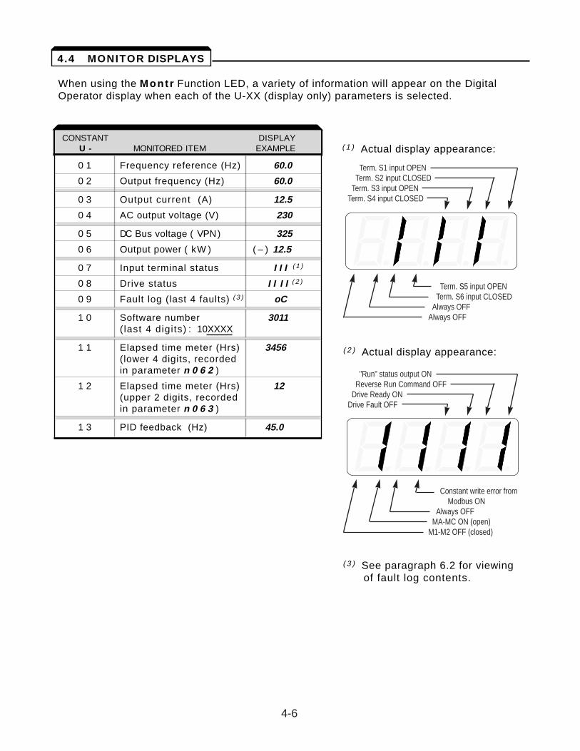
When using the Montr Function LED, a variety of information will appear on the DigitalOperator display when each of the U-XX (display only) parameters is selected.
CONSTANT DISPLAYUn- MONITORED ITEM EXAMPLE
0 1 Frequency reference (Hz) 60.0
0 2 Output frequency (Hz) 60.0
0 3 Output current (A) 12.5
0 4 AC output voltage (V) 230
0 5 DC Bus voltage ( VPN) 325
0 6 Output power ( kW ) ( – ) 12.5
0 7 Input terminal status I I I ( 1 )
0 8 Drive status I I I I ( 2 )
0 9 Fault log (last 4 faults) ( 3 ) oC
1 0 Software number 3011( last 4 digi ts) : 10XXXX
1 1 Elapsed time meter (Hrs) 3456(lower 4 digits, recorded in parameter n 0 6 2 )
1 2 Elapsed time meter (Hrs) 12(upper 2 digits, recordedin parameter n 0 6 3 )
1 3 PID feedback (Hz) 45.0
CONSTANT DISPLAYU - MONITORED ITEM EXAMPLE ( 1 ) Actual display appearance:
( 2 ) Actual display appearance:
( 3 ) See paragraph 6.2 for viewing of fault log contents.
Term. S5 input OPENTerm. S6 input CLOSED
Always OFFAlways OFF
Term. S1 input OPENTerm. S2 input CLOSED
Term. S3 input OPENTerm. S4 input CLOSED
"Run" status output ONReverse Run Command OFF
Drive Ready ONDrive Fault OFF
4-6
4.4 MONITOR DISPLAYS
Constant write error from Modbus ON
Always OFFMA-MC ON (open)
M1-M2 OFF (closed)
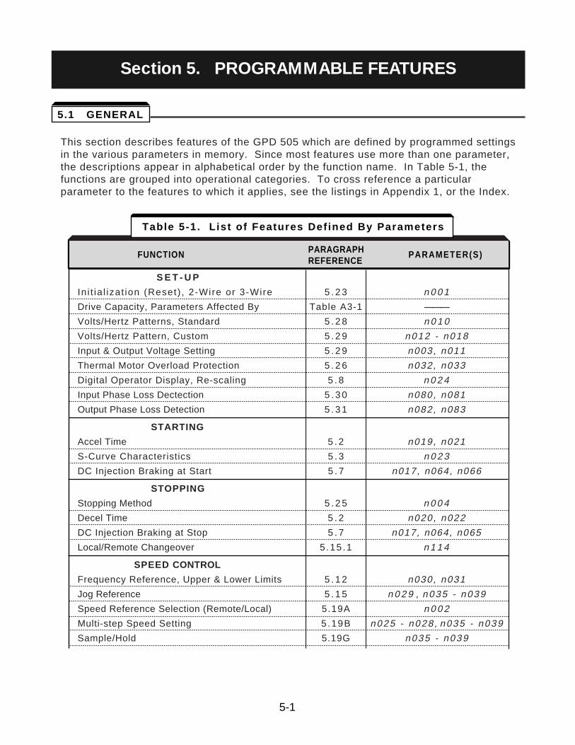
This section describes features of the GPD 505 which are defined by programmed settingsin the various parameters in memory. Since most features use more than one parameter,the descriptions appear in alphabetical order by the function name. In Table 5-1, thefunctions are grouped into operational categories. To cross reference a particularparameter to the features to which it applies, see the listings in Appendix 1, or the Index.
S E T - U P
In i t ia l izat ion (Reset) , 2-Wire or 3-Wire 5 . 2 3 n 0 0 1
Drive Capacity, Parameters Affected By Table A3-1 ———
Volts/Hertz Patterns, Standard 5 . 2 8 n 0 1 0
Volts/Hertz Pattern, Custom 5 . 2 9 n012 - n018
Input & Output Voltage Setting 5 . 2 9 n003, n011
Thermal Motor Overload Protection 5 . 2 6 n032, n033
Digital Operator Display, Re-scaling 5 . 8 n 0 2 4
Input Phase Loss Dectection 5 . 3 0 n080, n081
Output Phase Loss Detection 5 . 3 1 n082, n083
STARTING
Accel Time 5 . 2 n019, n021
S-Curve Characteristics 5 . 3 n 0 2 3
DC Injection Braking at Start 5 . 7 n017, n064, n066
STOPPING
Stopping Method 5 . 2 5 n 0 0 4
Decel Time 5 . 2 n020, n022
DC Injection Braking at Stop 5 . 7 n017, n064, n065
Local/Remote Changeover 5 .15 .1 n 1 1 4
SPEED CONTROL
Frequency Reference, Upper & Lower Limits 5 . 1 2 n030, n031
Jog Reference 5 . 1 5 n 0 2 9 , n035 - n039
Speed Reference Selection (Remote/Local) 5.19A n 0 0 2
Multi-step Speed Setting 5 .19B n025 - n028 , n035 - n039
Sample/Hold 5.19G n035 - n039
Table 5-1. List of Features Defined By Parameters
FUNCTION PARAGRAPH PARAMETER(S)REFERENCE
5-1
Section 5. PROGRAMMABLE FEATURES
5.1 GENERAL
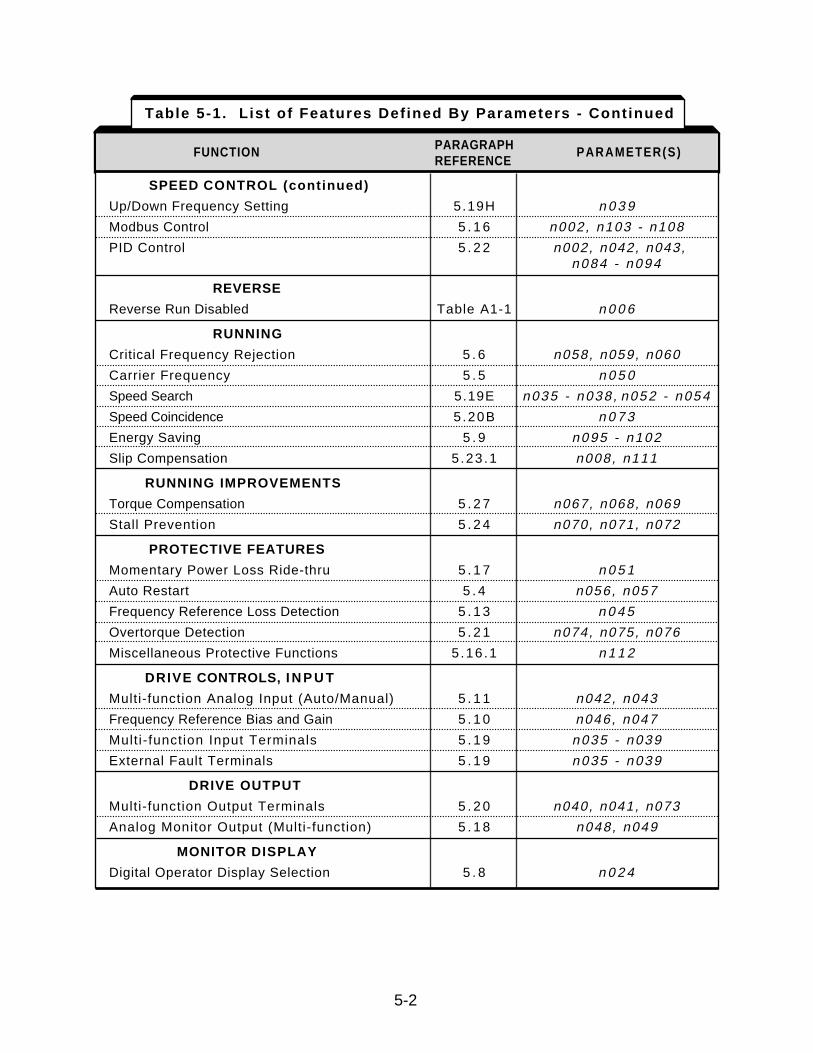
SPEED CONTROL (continued)
Up/Down Frequency Setting 5.19H n 0 3 9
Modbus Control 5 . 1 6 n002, n103 - n108
PID Control 5 . 2 2 n002, n042, n043,n084 - n094
REVERSE
Reverse Run Disabled Table A1-1 n 0 0 6
RUNNING
Critical Frequency Rejection 5 . 6 n058, n059, n060
Carrier Frequency 5 . 5 n 0 5 0
Speed Search 5.19E n035 - n038 , n052 - n054
Speed Coincidence 5.20B n 0 7 3
Energy Saving 5 . 9 n095 - n102
Slip Compensation 5 .23 .1 n008, n111
RUNNING IMPROVEMENTS
Torque Compensation 5 . 2 7 n067, n068, n069
Stall Prevention 5 . 2 4 n070, n071, n072
PROTECTIVE FEATURES
Momentary Power Loss Ride-thru 5 . 1 7 n 0 5 1
Auto Restart 5 . 4 n056, n057
Frequency Reference Loss Detection 5 . 1 3 n 0 4 5
Overtorque Detection 5 . 2 1 n074, n075, n076
Miscellaneous Protective Functions 5 .16 .1 n 1 1 2
DRIVE CONTROLS, I N P U T
Multi-function Analog Input (Auto/Manual) 5 . 1 1 n042, n043
Frequency Reference Bias and Gain 5 . 1 0 n046, n047
Mult i-function Input Terminals 5 . 1 9 n035 - n039
External Fault Terminals 5 . 1 9 n035 - n039
DRIVE OUTPUT
Multi-function Output Terminals 5 . 2 0 n040, n041, n073
Analog Monitor Output (Multi-function) 5 . 1 8 n048, n049
MONITOR DISPLAY
Digital Operator Display Selection 5 . 8 n 0 2 4
Table 5-1. List of Features Defined By Parameters - Continued
FUNCTION PARAGRAPH PARAMETER(S)REFERENCE
5-2
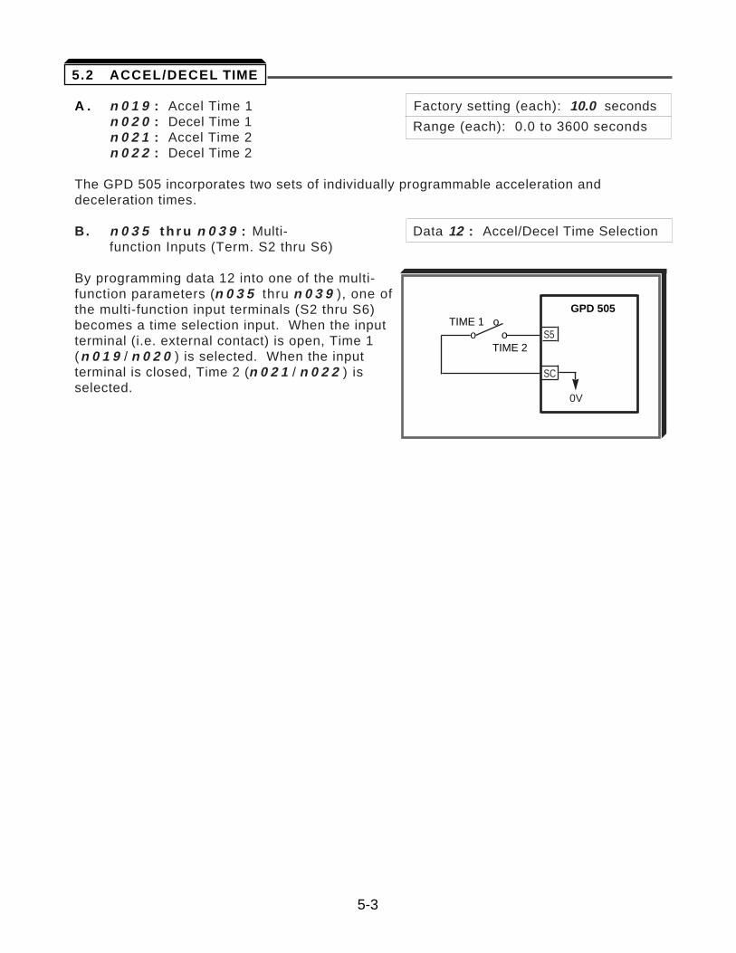
A . n 0 1 9 : Accel Time 1 Factory setting (each): 10.0 secondsn 0 2 0 : Decel Time 1 Range (each): 0.0 to 3600 secondsn 0 2 1 : Accel Time 2n 0 2 2 : Decel Time 2
The GPD 505 incorporates two sets of individually programmable acceleration anddeceleration times.
B. n 0 3 5 t h r u n 0 3 9 : Multi- Data 12 : Accel/Decel Time Selectionfunction Inputs (Term. S2 thru S6)
By programming data 12 into one of the multi-function parameters (n 0 3 5 thru n 0 3 9 ), one ofthe multi-function input terminals (S2 thru S6)becomes a time selection input. When the inputterminal (i.e. external contact) is open, Time 1(n 0 1 9 / n 0 2 0 ) is selected. When the inputterminal is closed, Time 2 (n 0 2 1 / n 0 2 2 ) isselected.
TIME 1 oo o
TIME 2
GPD 505
S5
SC
0V
5-3
5.2 ACCEL/DECEL TIME
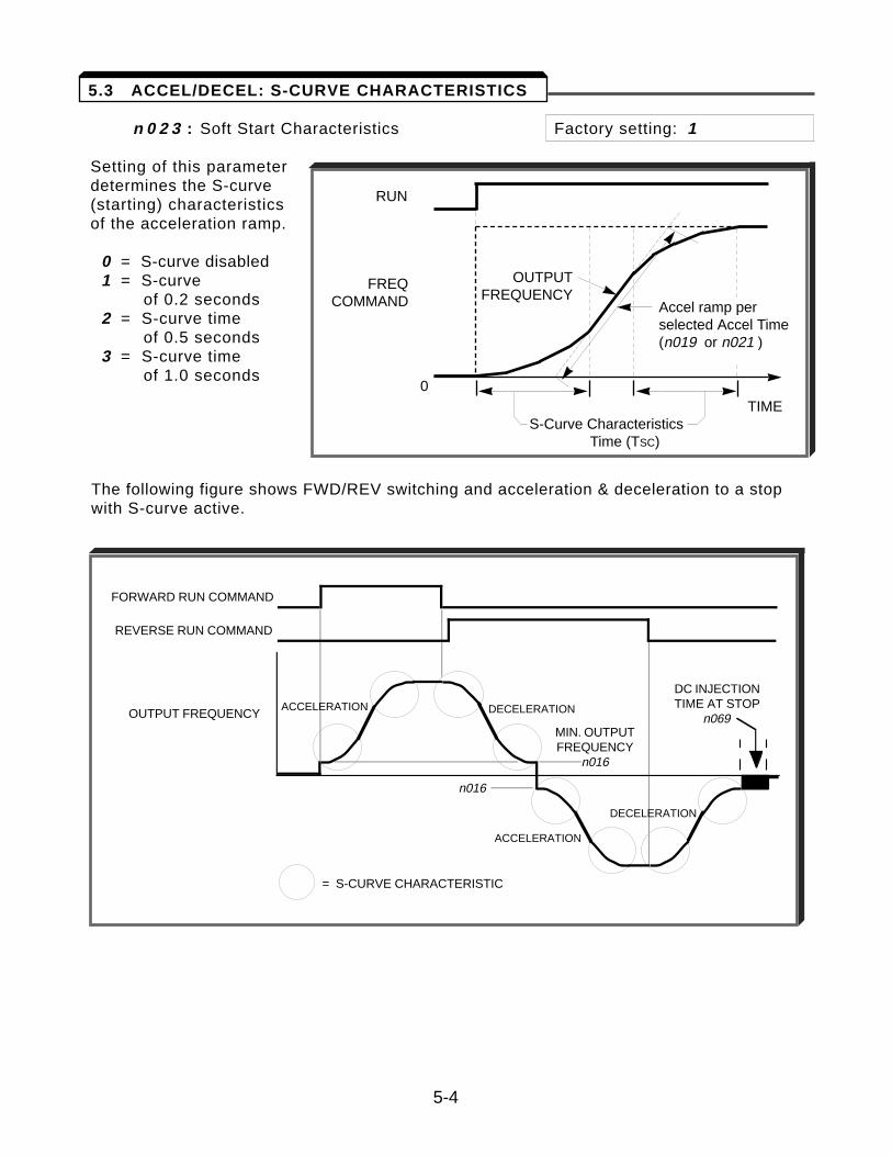
n 0 2 3 : Soft Start Characteristics Factory setting: 1
Setting of this parameterdetermines the S-curve(starting) characteristics of the acceleration ramp.
0 = S-curve disabled1 = S-curve
of 0.2 seconds2 = S-curve time
of 0.5 seconds3 = S-curve time
of 1.0 seconds
The following figure shows FWD/REV switching and acceleration & deceleration to a stopwith S-curve active.
RUN
FREQCOMMAND
0TIME
S-Curve Characteristics Time (TSC)
OUTPUTFREQUENCY
Accel ramp perselected Accel Time (n019 or n021 )
5-4
5.3 ACCEL/DECEL: S-CURVE CHARACTERISTICS
OUTPUT FREQUENCY
FORWARD RUN COMMAND
= S-CURVE CHARACTERISTIC
REVERSE RUN COMMAND
MIN. OUTPUTFREQUENCY
n016
n016
ACCELERATION DECELERATION
ACCELERATION
DC INJECTIONTIME AT STOP
n069
DECELERATION
5-5
A . n 0 5 6 : Number of Auto-Restart Attempts Factory setting: 0
Range: 0 - 10
When a fault occurs during operation, the GPD 505 can be programmed for an auto-restartoperation to automatically reset the fault. Auto-restart operation will use the number ofreset attempts set in this parameter, up to the maximum of 10. When set to " 0 ", noauto-restarts will be attempted.
• The following faults can be automatically reset:
oC: Overcurrent GF: Ground faultou: Overvoltage (OV) Uu1: Undervoltage (Power UV)
• The following conditions WILL NOT initiate auto-restart:
1. oL, EF , PUF or CPF fault.2. When OC or UV occurs during deceleration.3. When n 0 5 1 is programmed to stop during momentary power failure (data =
" 0 "). (See paragraph 5.17, MOMENTARY POWER LOSS RIDE-THRU. )
• The number of restart attempts available will be reset to the n 0 5 6 setting when:
1. 10 minutes has elapsed without a fault occurring.2. The RESET key, or external Fault Reset push button, is pressed.3. Power is removed from the Drive.
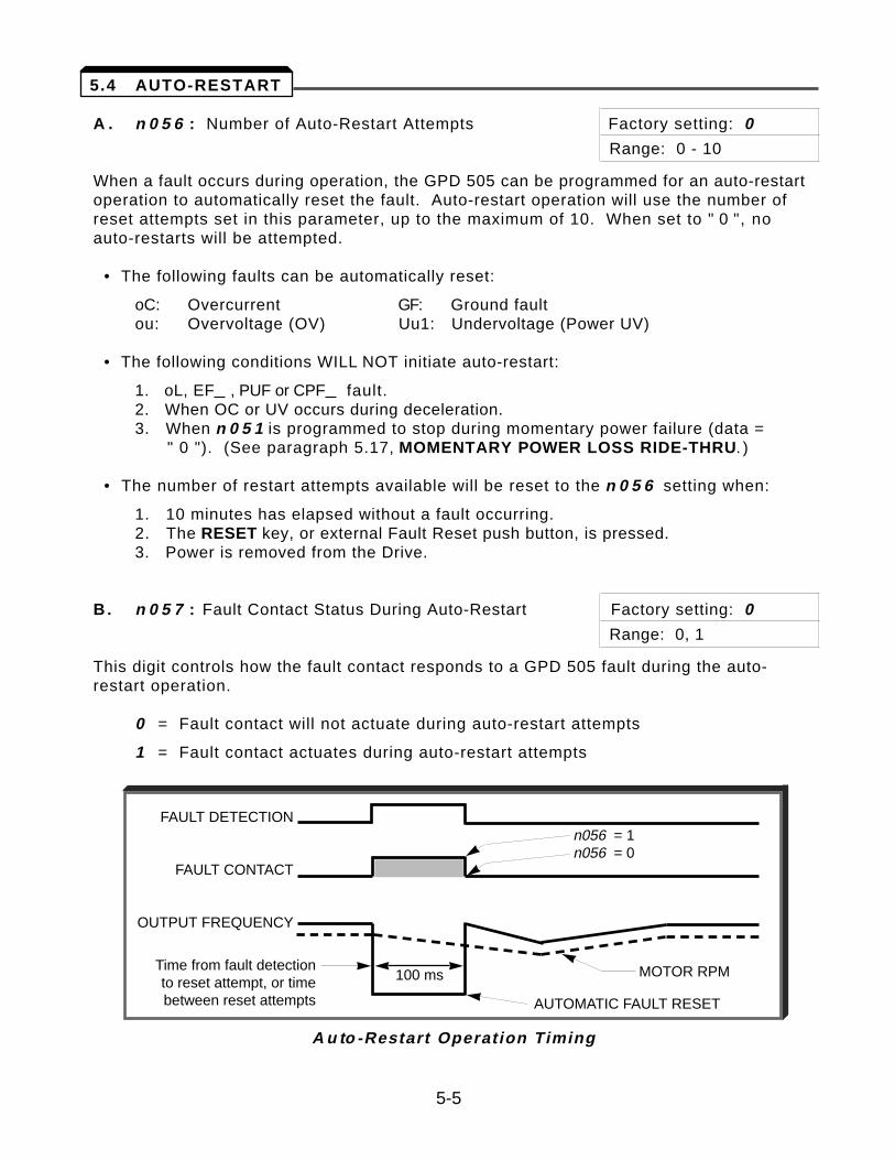
B. n 0 5 7 : Fault Contact Status During Auto-Restart Factory setting: 0
Range: 0, 1
This digit controls how the fault contact responds to a GPD 505 fault during the auto-restart operation.
0 = Fault contact will not actuate during auto-restart attempts
1 = Fault contact actuates during auto-restart attempts
A u to -Restart Operation Timing
FAULT DETECTION
FAULT CONTACT
OUTPUT FREQUENCY
n056 = 1n056 = 0
MOTOR RPM100 ms
AUTOMATIC FAULT RESET
Time from fault detectionto reset attempt, or timebetween reset attempts
5.4 AUTO-RESTART
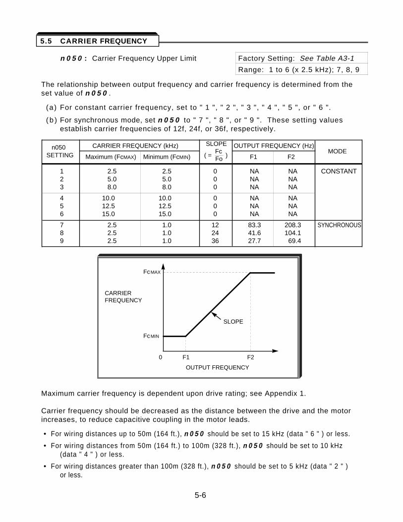
n 0 5 0 : Carrier Frequency Upper Limit Factory Setting: See Table A3-1
Range: 1 to 6 (x 2.5 kHz); 7, 8, 9
The relationship between output frequency and carrier frequency is determined from theset value of n 0 5 0 .
(a) For constant carrier frequency, set to " 1 ", " 2 ", " 3 ", " 4 ", " 5 ", or " 6 ".
( b ) For synchronous mode, set n 0 5 0 to " 7 ", " 8 ", or " 9 ". These setting values establish carrier frequencies of 12f, 24f, or 36f, respectively.
n050 CARRIER FREQUENCY (kHz) SLOPE OUTPUT FREQUENCY (Hz)
( = Fc
) MODE
SETTING Maximum (FcMAX) Minimum (FcMIN) Fo F1 F2
1 2.5 2.5 0 NA NA CONSTANT2 5.0 5.0 0 NA NA3 8.0 8.0 0 NA NA
4 10.0 10.0 0 NA NA5 12.5 12.5 0 NA NA6 15.0 15.0 0 NA NA
7 2.5 1.0 12 83.3 208.3 SYNCHRONOUS8 2.5 1.0 24 41.6 104.19 2.5 1.0 36 27.7 69.4
Maximum carrier frequency is dependent upon drive rating; see Appendix 1.
Carrier frequency should be decreased as the distance between the drive and the motorincreases, to reduce capacitive coupling in the motor leads.
• For wiring distances up to 50m (164 ft.), n 0 5 0 should be set to 15 kHz (data " 6 " ) or less.
• For wiring distances from 50m (164 ft.) to 100m (328 ft.), n 0 5 0 should be set to 10 kHz (data " 4 " ) or less.
• For wiring distances greater than 100m (328 ft.), n 0 5 0 should be set to 5 kHz (data " 2 " ) or less.
5-6
FcMAX
CARRIERFREQUENCY
SLOPE
FcMIN
0 F1 F2
OUTPUT FREQUENCY
5.5 CARRIER FREQUENCY
A . n 0 5 8 : Prohibited Frequency 1 Factory setting (each): 0.0n 0 5 9 : Prohibited Frequency 2 Range (each): 0.0 to 400.0 Hz
These parameters allow programming of up to two prohibited frequency points foreliminating problems with resonant vibration of the motor/machine. This feature does notactually eliminate the selected frequency values, but will accelerate and decelerate themotor through the prohibited bandwidth.
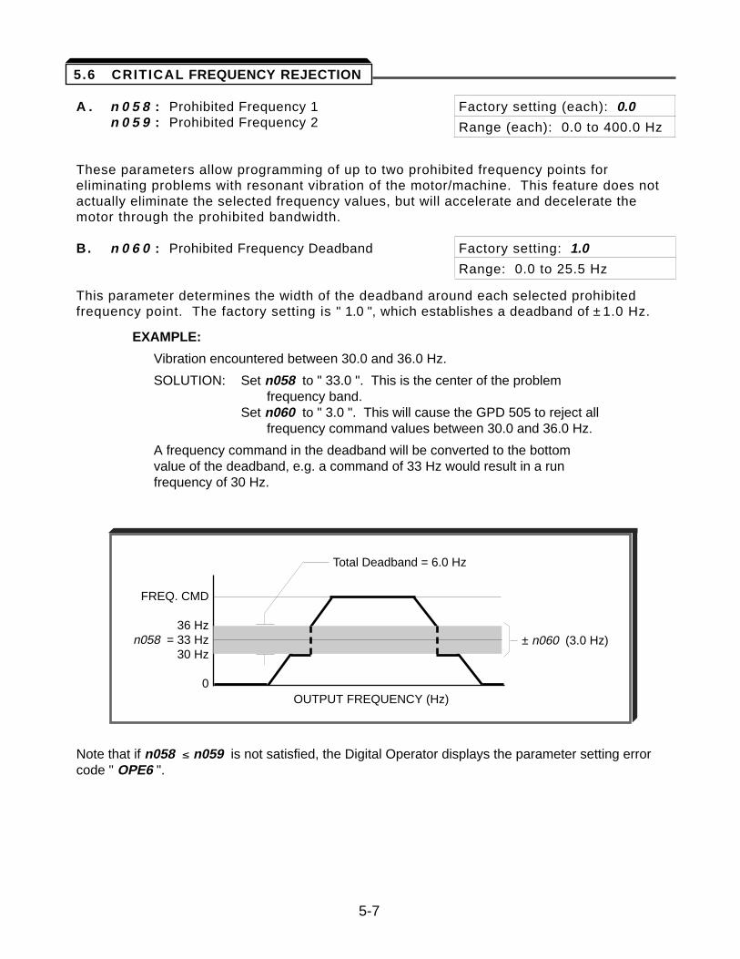
B. n 0 6 0 : Prohibited Frequency Deadband Factory setting: 1.0
Range: 0.0 to 25.5 Hz
This parameter determines the width of the deadband around each selected prohibitedfrequency point. The factory setting is " 1.0 ", which establishes a deadband of ± 1.0 Hz.
EXAMPLE:
Vibration encountered between 30.0 and 36.0 Hz.
SOLUTION: Set n058 to " 33.0 ". This is the center of the problem frequency band.
Set n060 to " 3.0 ". This will cause the GPD 505 to reject all frequency command values between 30.0 and 36.0 Hz.
A frequency command in the deadband will be converted to the bottom value of the deadband, e.g. a command of 33 Hz would result in a runfrequency of 30 Hz.
Note that if n058 ² n059 is not satisfied, the Digital Operator displays the parameter setting errorcode " OPE6 ".
FREQ. CMD
36 Hzn058 = 33 Hz
30 Hz
0
Total Deadband = 6.0 Hz
± n060 (3.0 Hz)
OUTPUT FREQUENCY (Hz)
5-7
5.6 CRITICAL FREQUENCY REJECTION
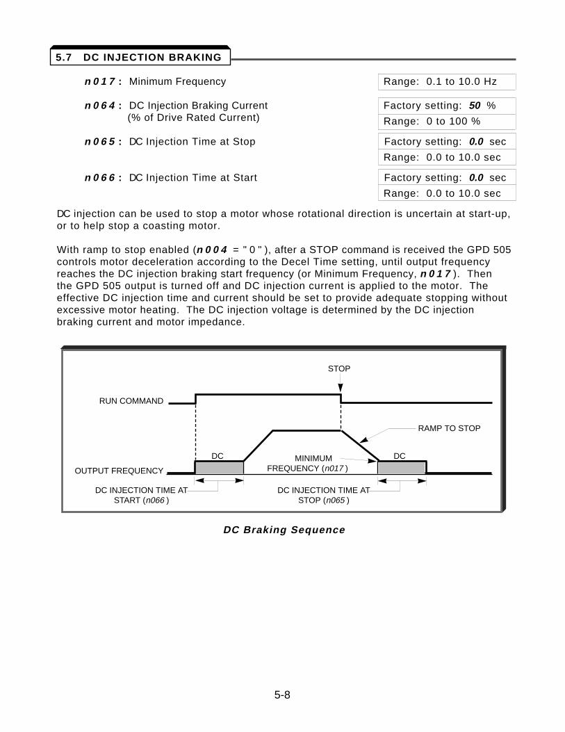
n 0 1 7 : Minimum Frequency Range: 0.1 to 10.0 Hz
n 0 6 4 : DC Injection Braking Current Factory setting: 50 %(% of Drive Rated Current) Range: 0 to 100 %
n 0 6 5 : DC Injection Time at Stop Factory setting: 0.0 sec
Range: 0.0 to 10.0 sec
n 0 6 6 : DC Injection Time at Start Factory setting: 0.0 sec
Range: 0.0 to 10.0 sec
DC injection can be used to stop a motor whose rotational direction is uncertain at start-up,or to help stop a coasting motor.
With ramp to stop enabled (n 0 0 4 = " 0 " ), after a STOP command is received the GPD 505controls motor deceleration according to the Decel Time setting, until output frequencyreaches the DC injection braking start frequency (or Minimum Frequency, n 0 1 7 ). Thenthe GPD 505 output is turned off and DC injection current is applied to the motor. Theeffective DC injection time and current should be set to provide adequate stopping withoutexcessive motor heating. The DC injection voltage is determined by the DC injectionbraking current and motor impedance.
DC Braking Sequence
5-8
5.7 DC INJECTION BRAKING
RUN COMMAND
OUTPUT FREQUENCY
STOP
RAMP TO STOP
DC DC
DC INJECTION TIME ATSTART (n066 )
MINIMUM FREQUENCY (n017 )
DC INJECTION TIME ATSTOP (n065 )
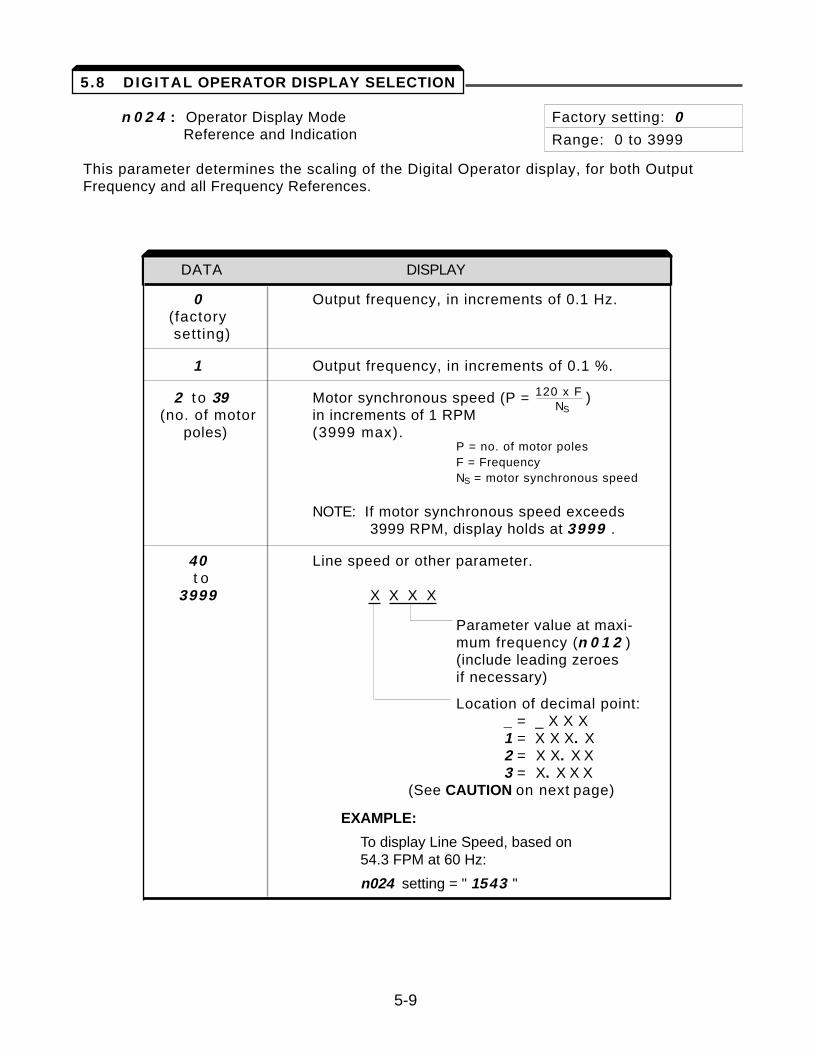
n 0 2 4 : Operator Display Mode Factory setting: 0Reference and Indication Range: 0 to 3999
This parameter determines the scaling of the Digital Operator display, for both OutputFrequency and all Frequency References.
DATA DISPLAY
0 Output frequency, in increments of 0.1 Hz.(factory setting)
1 Output frequency, in increments of 0.1 %.
2 t o 39 Motor synchronous speed (P = (no. of motor in increments of 1 RPM
poles) (3999 max).P = no. of motor polesF = FrequencyNS = motor synchronous speed
NOTE: If motor synchronous speed exceeds 3999 RPM, display holds at 3999 .
40 Line speed or other parameter. t o
3999 X X X X
Parameter value at maxi-mum frequency (n 0 1 2 )(include leading zeroes if necessary)
Location of decimal point:_ = _ X X X 1 = X X X. X2 = X X. X X3 = X. X X X
(See CAUTION on next page)
EXAMPLE:
To display Line Speed, based on 54.3 FPM at 60 Hz:
n024 setting = " 1543 "
DATA DISPLAY
5-9
120 x F )NS
5.8 DIGITAL OPERATOR DISPLAY SELECTION
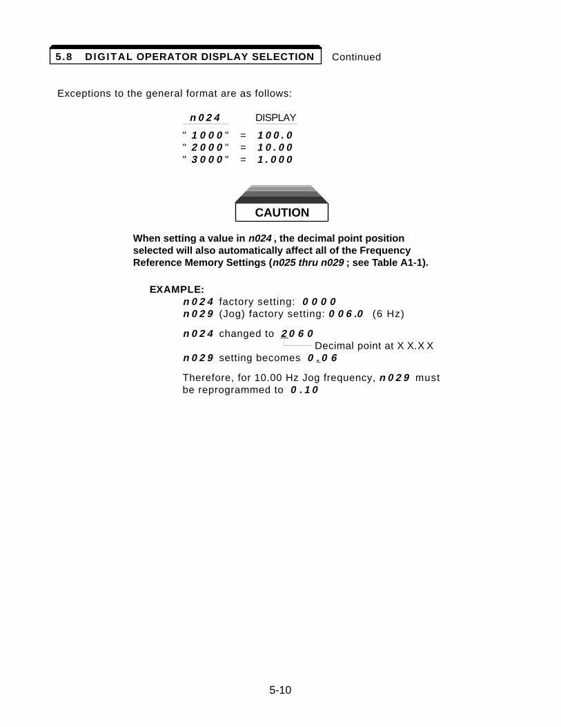
Continued
Exceptions to the general format are as follows:
n 0 2 4 DISPLAY
" 1 0 0 0 " = 1 0 0 . 0" 2 0 0 0 " = 1 0 . 0 0" 3 0 0 0 " = 1 . 0 0 0
CAUTION
When setting a value in n024 , the decimal point positionselected will also automatically affect all of the FrequencyReference Memory Settings (n025 thru n029 ; see Table A1-1).
EXAMPLE:n 0 2 4 factory setting: 0 0 0 0n 0 2 9 (Jog) factory setting: 0 0 6 .0 (6 Hz)
n 0 2 4 changed to 2 0 6 0Decimal point at X X.X X
n 0 2 9 setting becomes 0 . 0 6
Therefore, for 10.00 Hz Jog frequency, n 0 2 9 must be reprogrammed to 0 . 1 0
5-10
5.8 DIGITAL OPERATOR DISPLAY SELECTION
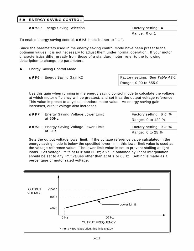
n 0 9 5 : Energy Saving Selection Factory setting: 0
Range: 0 or 1
To enable energy saving control, n 0 9 5 must be set to " 1 ".
Since the parameters used in the energy saving control mode have been preset to theoptimum values, it is not necessary to adjust them under normal operation. If your motorcharacteristics differ greatly from those of a standard motor, refer to the followingdescription to change the parameters.
A . Energy Saving Control Mode
n 0 9 6 : Energy Saving Gain K2 Factory setting: See Table A3-1
Range: 0.00 to 655.0
Use this gain when running in the energy saving control mode to calculate the voltage at which motor efficiency will be greatest, and set it as the output voltage reference. This value is preset to a typical standard motor value. As energy saving gain increases, output voltage also increases.
n 0 9 7 : Energy Saving Voltage Lower Limit Factory setting: 5 0 %at 60Hz Range: 0 to 120 %
n 0 9 8 : Energy Saving Voltage Lower Limit Factory setting: 1 2 %at 6Hz Range: 0 to 25 %
Sets the output voltage lower limit. If the voltage reference value calculated in the energy saving mode is below the specified lower limit, this lower limit value is used as the voltage reference value. The lower limit value is set to prevent stalling at light loads. Set voltage limits at 6Hz and 60Hz; a value obtained by linear interpolation should be set to any limit values other than at 6Hz or 60Hz. Setting is made as a percentage of motor rated voltage.
5-11
5.9 ENERGY SAVING CONTROL
OUTPUT 255V *VOLTAGE
n097
Lower Limitn098
6 Hz 60 Hz
OUTPUT FREQUENCY
* For a 460V class drive, this limit is 510V
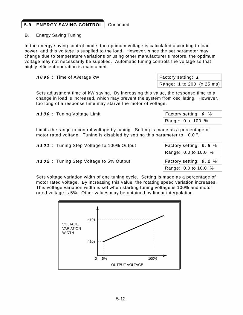
Continued
B. Energy Saving Tuning
In the energy saving control mode, the optimum voltage is calculated according to loadpower, and this voltage is supplied to the load. However, since the set parameter maychange due to temperature variations or using other manufacturer’s motors, the optimumvoltage may not necessarily be supplied. Automatic tuning controls the voltage so thathighly efficient operation is maintained.
n 0 9 9 : Time of Average kW Factory setting: 1
Range: 1 to 200 (x 25 ms)
Sets adjustment time of kW saving. By increasing this value, the response time to a change in load is increased, which may prevent the system from oscillating. However, too long of a response time may starve the motor of voltage.
n 1 0 0 : Tuning Voltage Limit Factory setting: 0 %
Range: 0 to 100 %
Limits the range to control voltage by tuning. Setting is made as a percentage of motor rated voltage. Tuning is disabled by setting this parameter to " 0.0 ".
n 1 0 1 : Tuning Step Voltage to 100% Output Factory setting: 0 . 5 %
Range: 0.0 to 10.0 %
n 1 0 2 : Tuning Step Voltage to 5% Output Factory setting: 0 . 2 %
Range: 0.0 to 10.0 %
Sets voltage variation width of one tuning cycle. Setting is made as a percentage of motor rated voltage. By increasing this value, the rotating speed variation increases. This voltage variation width is set when starting tuning voltage is 100% and motor rated voltage is 5%. Other values may be obtained by linear interpolation.
5-12
5.9 ENERGY SAVING CONTROL
n101VOLTAGEVARIATIONWIDTH
n102
0 5% 100%
OUTPUT VOLTAGE
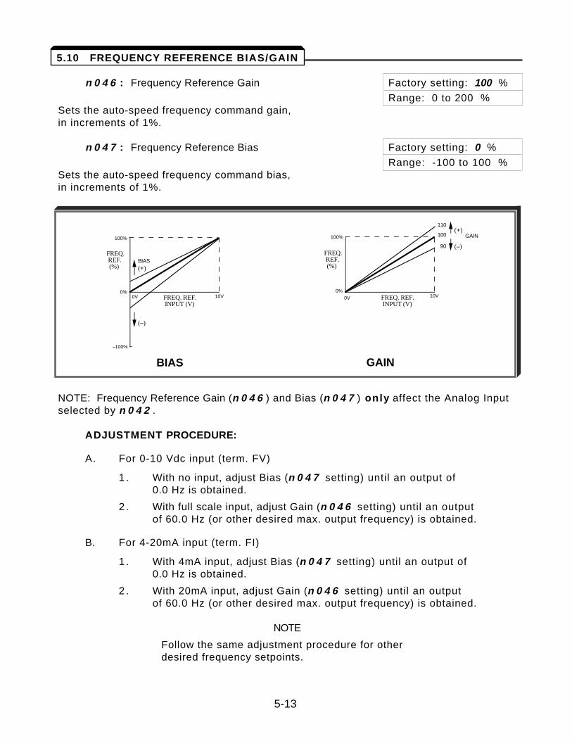
n 0 4 6 : Frequency Reference Gain Factory setting: 100 %
Range: 0 to 200 %Sets the auto-speed frequency command gain, in increments of 1%.
n 0 4 7 : Frequency Reference Bias Factory setting: 0 %
Range: -100 to 100 %Sets the auto-speed frequency command bias, in increments of 1%.
NOTE: Frequency Reference Gain (n 0 4 6 ) and Bias (n 0 4 7 ) only affect the Analog Inputselected by n 0 4 2 .
ADJUSTMENT PROCEDURE:
A. For 0-10 Vdc input (term. FV)
1 . With no input, adjust Bias (n 0 4 7 setting) until an output of 0.0 Hz is obtained.
2 . With full scale input, adjust Gain (n 0 4 6 setting) until an output of 60.0 Hz (or other desired max. output frequency) is obtained.
B. For 4-20mA input (term. FI)
1 . With 4mA input, adjust Bias (n 0 4 7 setting) until an output of 0.0 Hz is obtained.
2 . With 20mA input, adjust Gain (n 0 4 6 setting) until an output of 60.0 Hz (or other desired max. output frequency) is obtained.
NOTE
Follow the same adjustment procedure for otherdesired frequency setpoints.
5-13
10VFREQ. REF. INPUT (V)
FREQ. REF. INPUT (V)
FREQ. REF. (%)
FREQ. REF. (%)
BIAS
GAIN
(+)
(–)
110
100
90
0V
100%
0%
–100%
10V0V
100%
0%
(+)
(–)
BIAS GAIN
5.10 FREQUENCY REFERENCE BIAS/GAIN
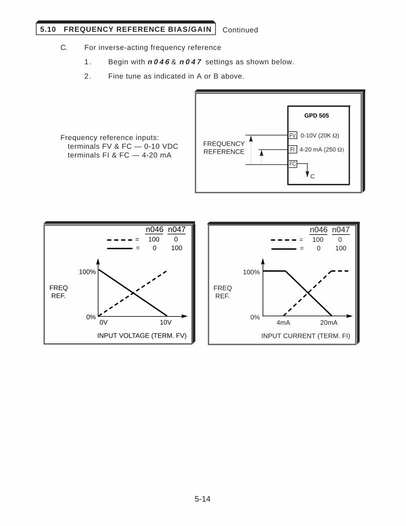
Continued
C. For inverse-acting frequency reference
1 . Begin with n 0 4 6 & n 0 4 7 settings as shown below.
2 . Fine tune as indicated in A or B above.
Frequency reference inputs:terminals FV & FC — 0-10 VDCterminals FI & FC — 4-20 mA
5-14
5.10 FREQUENCY REFERENCE BIAS/GAIN
GPD 505
FV 0-10V (20K W)
FI 4-20 mA (250 W)
FC
C
FREQUENCYREFERENCE
n046 n047= 100 0= 0 100
100%
FREQREF.
0%4mA 20mA
INPUT CURRENT (TERM. FI)
n046 n047= 100 0= 0 100
100%
FREQREF.
0%0V 10V
INPUT VOLTAGE (TERM. FV)
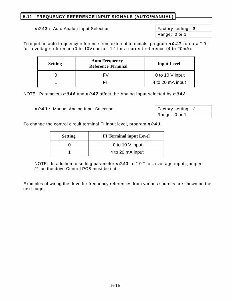
n 0 4 2 : Auto Analog Input Selection Factory setting: 0Range: 0 or 1
To input an auto frequency reference from external terminals, program n 0 4 2 to data " 0 "for a voltage reference (0 to 10V) or to " 1 " for a current reference (4 to 20mA).
SettingAuto Frequency
Input LevelReference Terminal
0 FV 0 to 10 V input
1 FI 4 to 20 mA input
NOTE: Parameters n 0 4 6 and n 0 4 7 affect the Analog Input selected by n 0 4 2 .
n 0 4 3 : Manual Analog Input Selection Factory setting: 1Range: 0 or 1
To change the control circuit terminal FI input level, program n 0 4 3 .
Setting FI Terminal input Level
0 0 to 10 V input
1 4 to 20 mA input
NOTE: In addition to setting parameter n 0 4 3 to " 0 " for a voltage input, jumper J1 on the drive Control PCB must be cut.
Examples of wiring the drive for frequency references from various sources are shown on thenext page.
5-15
5.11 FREQUENCY REFERENCE INPUT SIGNALS (AUTO/MANUAL)
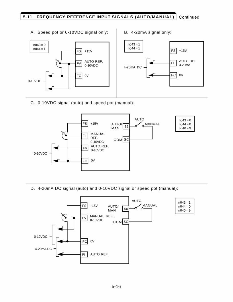
Continued
A. Speed pot or 0-10VDC signal only: B. 4-20mA signal only:
C. 0-10VDC signal (auto) and speed pot (manual):
D. 4-20mA DC signal (auto) and 0-10VDC signal or speed pot (manual):
5-16
5.11 FREQUENCY REFERENCE INPUT SIGNALS (AUTO/MANUAL)
n043 = 0n044 = 1
FS
FV
FC–
+
+15V
AUTO REF.0-10VDC
0V
0-10VDC
n043 = 0n044 = 0n040 = 9
FS
FI
–
+
+15V
MANUALREF.0-10VDC
0V
0-10VDC
FC
FVAUTO REF.0-10VDC
SC
S6
COM
AUTO/MAN
AUTOMANUAL
n043 = 1n044 = 0n040 = 9
FS
FV
–
+
+15V
MANUAL REF.0-10VDC
AUTO REF.
4-20mA DC
FI
FC 0V
SC
S6
COM
AUTO/MAN
AUTOMANUAL
+
0-10VDC
n043 = 1n044 = 1
FS
FI
FC–
+
+15V
AUTO REF.4-20mA
0V
4-20mA DC
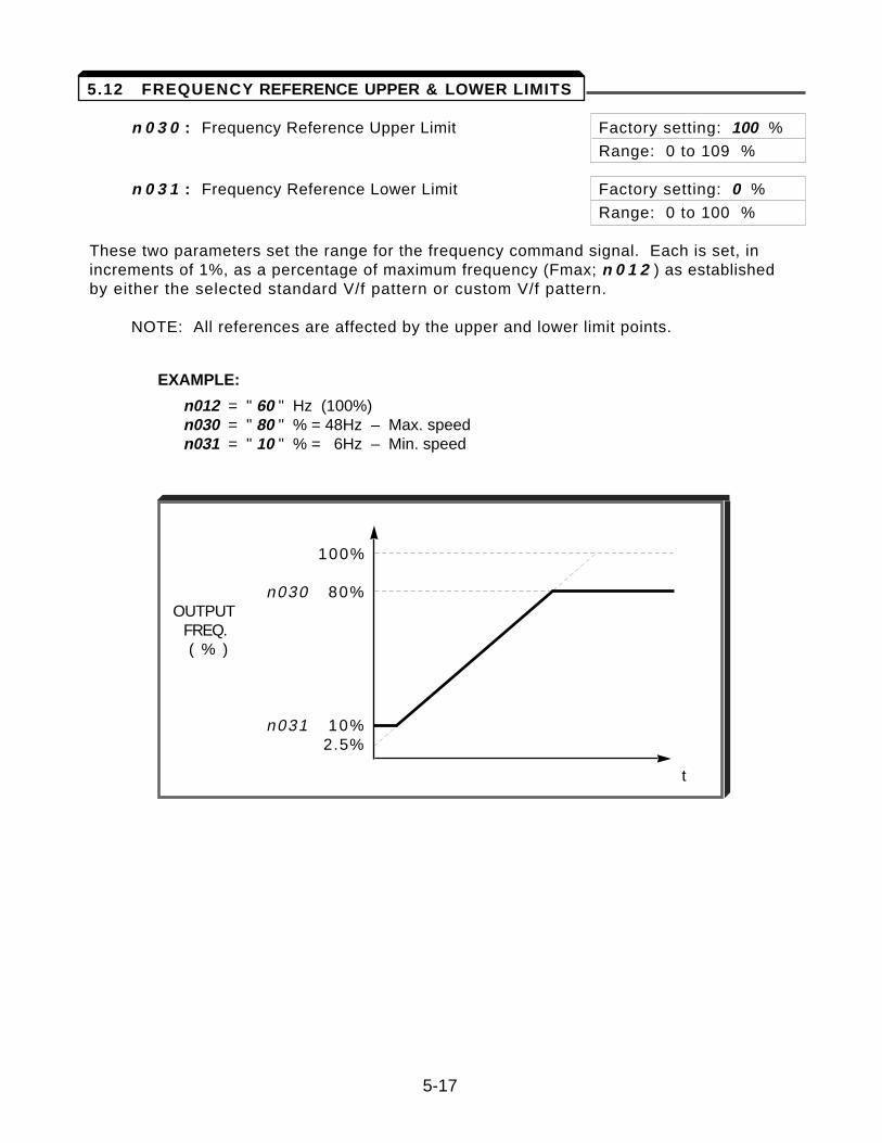
n 0 3 0 : Frequency Reference Upper Limit Factory setting: 100 %
Range: 0 to 109 %
n 0 3 1 : Frequency Reference Lower Limit Factory setting: 0 %
Range: 0 to 100 %
These two parameters set the range for the frequency command signal. Each is set, inincrements of 1%, as a percentage of maximum frequency (Fmax; n 0 1 2 ) as establishedby either the selected standard V/f pattern or custom V/f pattern.
NOTE: All references are affected by the upper and lower limit points.
EXAMPLE:
n012 = " 60 " Hz (100%)n030 = " 80 " % = 48Hz – Max. speedn031 = " 10 " % = 6Hz – Min. speed
100%
n030 80%OUTPUT
FREQ.( % )
n031 10%2.5%
t
5-17
5.12 FREQUENCY REFERENCE UPPER & LOWER LIMITS
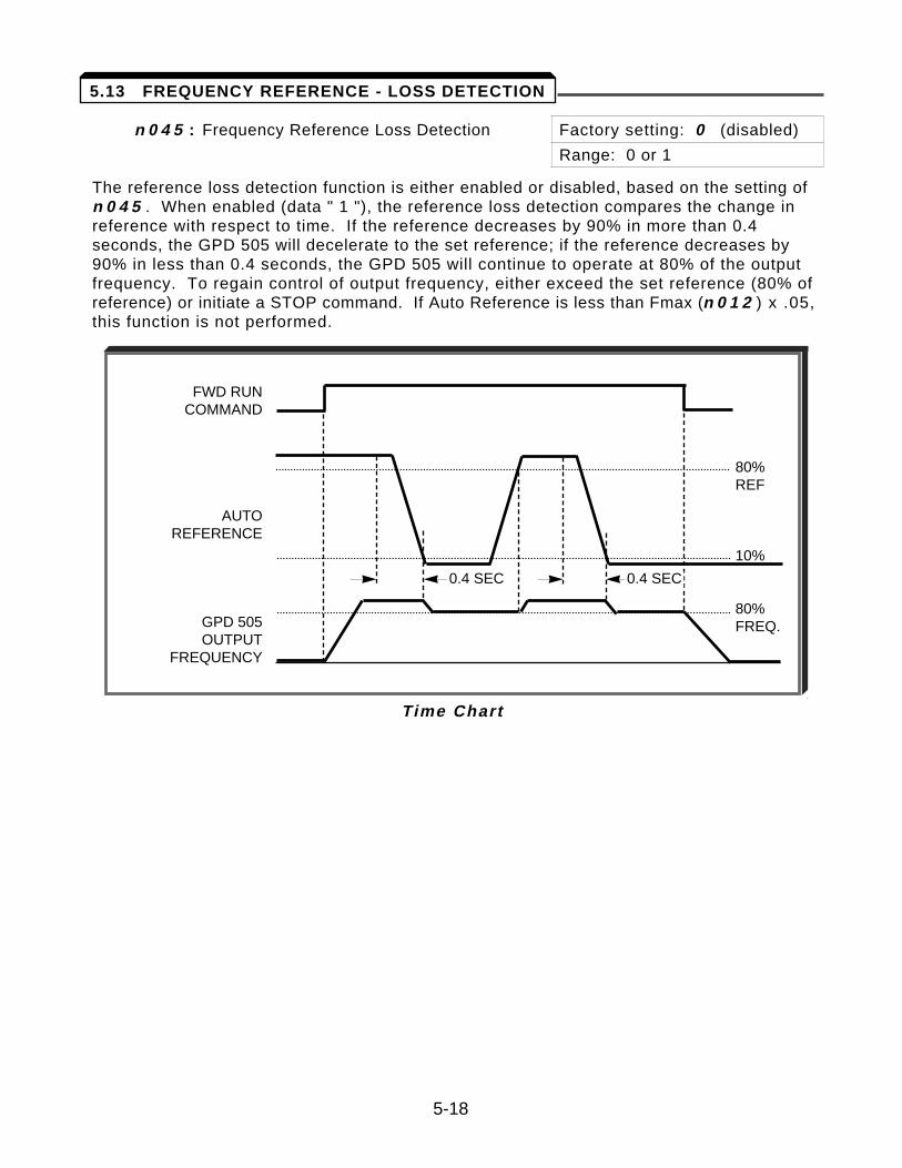
n 0 4 5 : Frequency Reference Loss Detection Factory setting: 0 (disabled)
Range: 0 or 1
The reference loss detection function is either enabled or disabled, based on the setting ofn 0 4 5 . When enabled (data " 1 "), the reference loss detection compares the change inreference with respect to time. If the reference decreases by 90% in more than 0.4seconds, the GPD 505 will decelerate to the set reference; if the reference decreases by90% in less than 0.4 seconds, the GPD 505 will continue to operate at 80% of the outputfrequency. To regain control of output frequency, either exceed the set reference (80% ofreference) or initiate a STOP command. If Auto Reference is less than Fmax (n 0 1 2 ) x .05,this function is not performed.
FWD RUNCOMMAND
AUTOREFERENCE
GPD 505OUTPUT
FREQUENCY
80%REF
10%
80%FREQ.
0.4 SEC 0.4 SEC
Time Chart
5-18
5.13 FREQUENCY REFERENCE - LOSS DETECTION
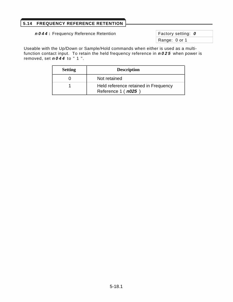
n 0 4 4 : Frequency Reference Retention Factory setting: 0
Range: 0 or 1
Useable with the Up/Down or Sample/Hold commands when either is used as a multi-function contact input. To retain the held frequency reference in n 0 2 5 when power isremoved, set n 0 4 4 to " 1 " .
Setting Description
0 Not retained
1 Held reference retained in Frequency Reference 1 ( n025 )
5-18.1
5.14 FREQUENCY REFERENCE RETENTION
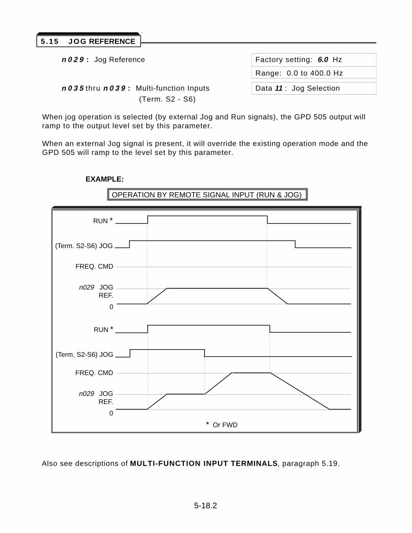
n 0 2 9 : Jog Reference Factory setting: 6.0 Hz
Range: 0.0 to 400.0 Hz
n 0 3 5 thru n 0 3 9 : Multi-function Inputs Data 11 : Jog Selection
(Term. S2 - S6)
When jog operation is selected (by external Jog and Run signals), the GPD 505 output willramp to the output level set by this parameter.
When an external Jog signal is present, it will override the existing operation mode and theGPD 505 will ramp to the level set by this parameter.
EXAMPLE:
OPERATION BY REMOTE SIGNAL INPUT (RUN & JOG)
Also see descriptions of MULTI-FUNCTION INPUT TERMINALS, paragraph 5.19.
5-18.2
5 .15 JOG REFERENCE
FREQ. CMD
n029 JOGREF.
0
FREQ. CMD
n029 JOGREF.
0
* Or FWD
RUN *
(Term. S2-S6) JOG
RUN *
(Term. S2-S6) JOG
n 1 1 4 : Local/Remote Changeover Factory setting: 1
Range: 0 or 1
When n 1 1 4 = 1, if the STOP key of the Digital Operator is pressed during operation atexternal terminal and function is changed from “Local” to “Remote”, the motor runs afterchangeover.
When n 1 1 4 = 0, if the Run comand is changed over by n 0 0 2 , or “Local/Remote” button,the motor does not stop until a Stop command is input.
5-19
5.15.1 LOCAL/REMOTE CHANGEOVER
The GPD 505 can perform serial communication by using a programmable controller (PLC)and MODBUSÔ protocol. MODBUS is composed of one master PLC and 1 to 31 (maximum)slave units (GPD 505s). In serial communication between the master and slaves, the masteralways starts transmission and the slaves respond to it.
The master communicates with one slave at a time. Address numbers are assigned to eachslave in advance, and the master specifies an address to communicate with. The slavewhich receives the command from the master executes the function, and then responds tothe master.
A . Communication Specifications
• Interface : RS-232C (standard); RS-485, RS-422 (option - requires communication interface card CM086)
• Synchronization : Asynchronous
• Transmission parameters : Baud rate — Selectable from 2400, 4800,9600 BPS (n 1 0 7 )
Data length — Fixed to 8 bitsParity — Parity / no parity, even / odd
selectable (n 1 0 8 )Stop bit — Fixed to 1 bit
• Protocol : MODBUS
• Maximum number to units to be connected : 31 units (when RS-485 is used)
B. Sending/Receiving Data
Data that can be sent and received are run/stop commands, frequency reference, faultreset, drive status, and setting and reading of parameters.
n 0 0 2 : Operation Mode Selection Factory setting: 3
Range: 0 to 8
Select the run command and frequency reference input method in n 0 0 2 . To provide a run command and frequency reference by communication, set this data to " 4 " thru " 8 ". Monitoring of run status, parameter setting/reading, fault reset and multi-function input command from the PLC are enabled. The multi-function input command is OR’ed with the command input from control circuit terminals S2-S6.
n 0 3 5 thru n 0 3 9 : Multi-function Inputs Data 6 : Serial communication/(Term. S2-S6) Digital Operator
Selects operation by serial communication or by external terminal. If the status of this command input is changed while the drive is running, the selection is ignored until the next time the drive is stopped.
Open : Run according to the setting of Operation Mode Selection (n 0 0 2 )Closed : Run by frequency reference and run command from serial
communication
5-20
5.16 MODBUS CONTROL
Continued
EXAMPLE: n 0 0 2 setting is " 3 ".
Open : Run by frequency reference from control circuit terminals FV, FI and run command from control circuit terminals S1, S2.
Closed : Run by frequency reference and run command from serial communication.
n 1 0 5 : Modbus Frequency Resolution Factory setting: 0
Range: 0 to 3
The frequency resolution from the PLC and in the frequency reference and output frequency monitor (by communication) are selected with this parameter. The output frequency resolution of the GPD 505 is 0.1 Hz. Even if the Modbus resolution is changed to 0.01 Hz in n 1 0 5 , the value in the hundredths digit of 0.01 Hz of the received frequency reference is rounded off internally. When 30,000/100% in units of 0.1% is selected, the value is also rounded off.
n 1 0 6 : Modbus Slave Address Factory setting: 0
Range: 0 to 31
Each slave GPD 505 on the same transmission line must be given a unique address.
n 1 0 7 : Modbus Baud Rate Factory setting: 2
Range: 0 to 2
Selects the baud rate, as indicated by the following table:
Setting Baud Rate (BPS)
0 2400
1 4800
2 9600
n 1 0 8 : Modbus Parity Selection Factory setting: 1
Range: 0 to 2
Selects the parity, as indicated by the following table:
Setting Parity
0 None
1 Even
2 Odd
NOTE: To change the values set in n 1 0 6 thru n 1 0 8 and enable the new settings, it is necessary to turn OFF power to the Drive, then turn it ON again.
5-21
5.16 MODBUS CONTROL
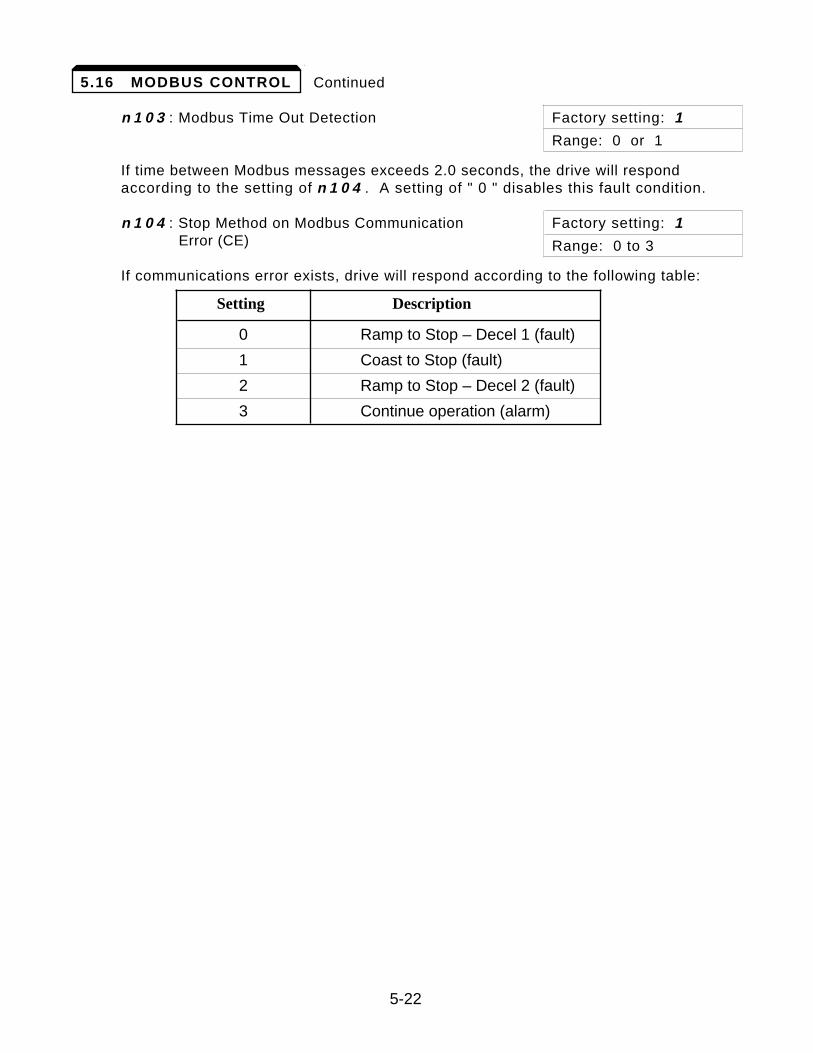
Continued
n 1 0 3 : Modbus Time Out Detection Factory setting: 1
Range: 0 or 1
If time between Modbus messages exceeds 2.0 seconds, the drive will respond according to the setting of n 1 0 4 . A setting of " 0 " disables this fault condition.
n 1 0 4 : Stop Method on Modbus Communication Factory setting: 1Error (CE) Range: 0 to 3
If communications error exists, drive will respond according to the following table:
Setting Description
0 Ramp to Stop – Decel 1 (fault)
1 Coast to Stop (fault)
2 Ramp to Stop – Decel 2 (fault)
3 Continue operation (alarm)
5-22
5.16 MODBUS CONTROL

n 1 1 2 : Operator Connection Fault Detection Factory setting: 0Selection Range: 0 or 1
Set this parameter to “1” only if the drive should shut down immediately if the DigitalOperator is disconnected while the drive is running. When set to “0”, the fault will notoccur until after the drive has been stopped.
5-22.1
5.16.1 MISCELLANEOUS PROTECTIVE FUNCTIONS
n 0 5 1 : Momentary Power Loss Ride-thru 0 = Disabled (Factory setting)Protection 1 = Enabled – 2 sec. power loss
ride-thru2 = Enabled – indefinite power loss
ride-thru, provided control power is maintained
The setting of this parameter either enables or disables the ride-thru feature of the GPD 505. If disabled, the unit will stop immediately whenever a power loss occurs. Ifenabled, the GPD 505 will continue to operate during a momentary power loss of up to80%, but if the loss exceeds the identified time period, the GPD 505 will stop.
n 0 5 5 : Power Loss Ride-Thru Factory setting: See Table A3-1Deactivation Time Range: 0.0 to 2.0 seconds
If the loss exceeds the length of time identified by n 0 5 5 , the GPD 505 will stop. Thefactory setting of this parameter, in 0.1 second increments, is related to the GPD 505’srating.
Note that the RUN command must be maintained throughout the ride-thru period. If n 0 5 1is set to " 2 ", a " Uu " alarm is displayed during power loss, and no fault signal is output atterminals M1 & M2 or MA, MB & MC.
5-22.2
5.17 MOMENTARY POWER LOSS RIDE-THRU
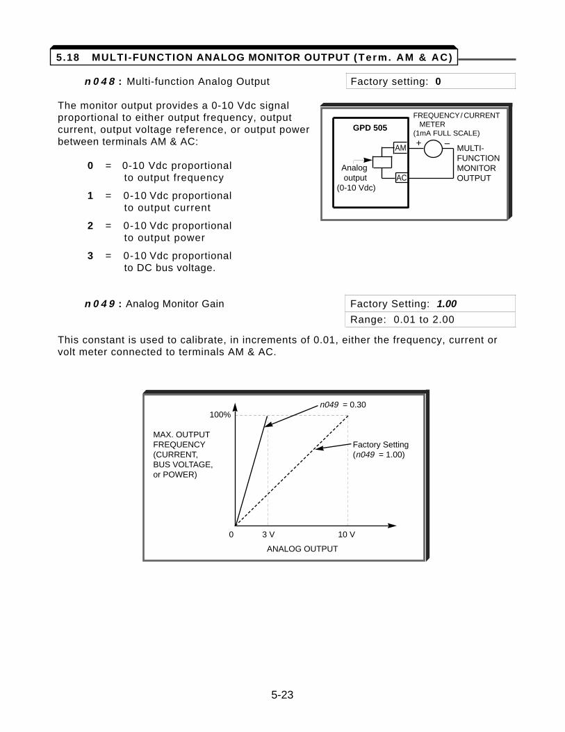
n 0 4 8 : Multi-function Analog Output Factory setting: 0
The monitor output provides a 0-10 Vdc signalproportional to either output frequency, outputcurrent, output voltage reference, or output powerbetween terminals AM & AC:
0 = 0-10 Vdc proportional to output frequency
1 = 0-10 Vdc proportional to output current
2 = 0-10 Vdc proportional to output power
3 = 0-10 Vdc proportional to DC bus voltage.
n 0 4 9 : Analog Monitor Gain Factory Setting: 1.00
Range: 0.01 to 2.00
This constant is used to calibrate, in increments of 0.01, either the frequency, current orvolt meter connected to terminals AM & AC.
5-23
GPD 505
AM
Analogoutput AC
(0-10 Vdc)
MULTI-FUNCTIONMONITOROUTPUT
+ –
FREQUENCY/ CURRENTMETER
(1mA FULL SCALE)
5.18 MULTI-FUNCTION ANALOG MONITOR OUTPUT (Term. AM & AC)
n049 = 0.30100%
MAX. OUTPUTFREQUENCY Factory Setting(CURRENT, (n049 = 1.00)BUS VOLTAGE, or POWER)
0 3 V 10 V
ANALOG OUTPUT
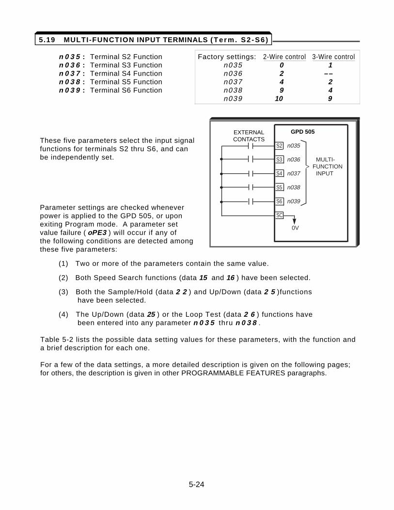
n 0 3 5 : Terminal S2 Function Factory settings: 2-Wire control 3-Wire controln 0 3 6 : Terminal S3 Function n035 0 1 n 0 3 7 : Terminal S4 Function n036 2 ––n 0 3 8 : Terminal S5 Function n037 4 2 n 0 3 9 : Terminal S6 Function n038 9 4
n039 10 9
These five parameters select the input signal functions for terminals S2 thru S6, and can be independently set.
Parameter settings are checked whenever power is applied to the GPD 505, or upon exiting Program mode. A parameter set value failure ( oPE3 ) will occur if any of the following conditions are detected among these five parameters:
(1) Two or more of the parameters contain the same value.
(2) Both Speed Search functions (data 15 and 16 ) have been selected.
(3) Both the Sample/Hold (data 2 2 ) and Up/Down (data 2 5 )functions have been selected.
(4) The Up/Down (data 25 ) or the Loop Test (data 2 6 ) functions have been entered into any parameter n 0 3 5 thru n 0 3 8 .
Table 5-2 lists the possible data setting values for these parameters, with the function anda brief description for each one.
For a few of the data settings, a more detailed description is given on the following pages;for others, the description is given in other PROGRAMMABLE FEATURES paragraphs.
EXTERNALCONTACTS
GPD 505
S2 n035
S3 n036 MULTI-> FUNCTION
S4 n037 INPUT
S5 n038
S6 n039
SC
0V
•
•
•
•
5-24
5.19 MULTI-FUNCTION INPUT TERMINALS ( T e r m . S 2 - S 6 )
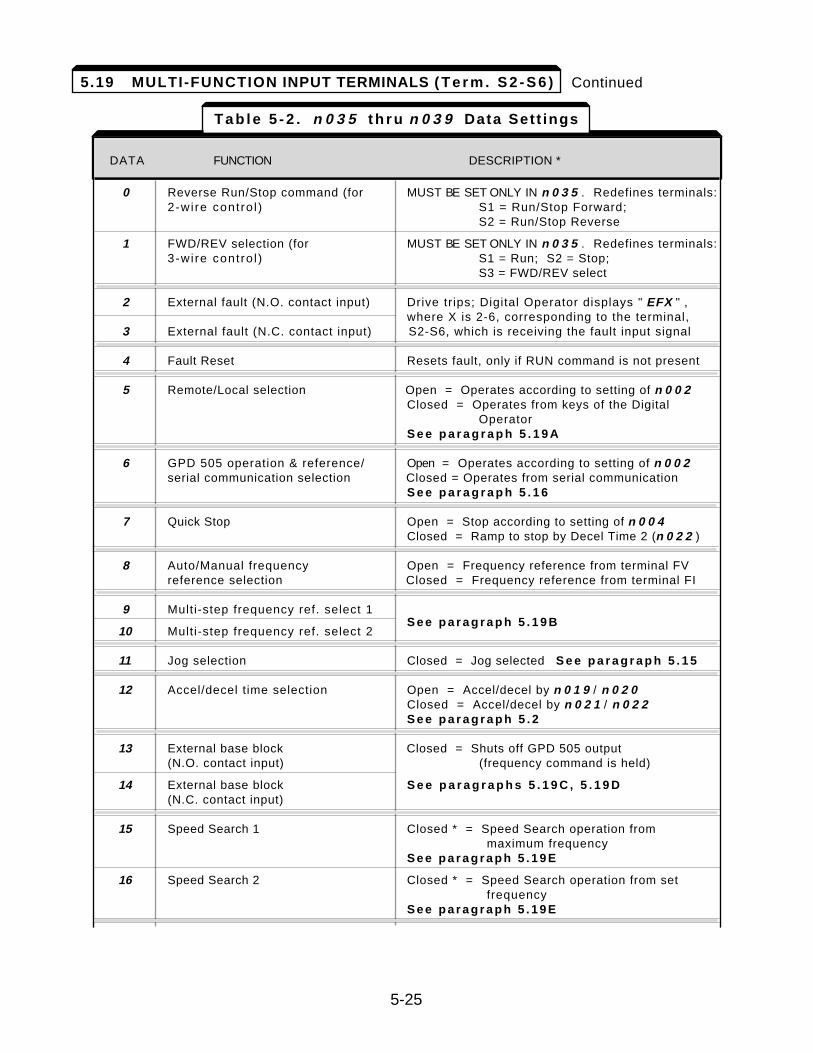
Continued
DESCRIPTIONDATA FUNCTION Signal Levels: 0 = state; 1 = pulse
0 Reverse Run/Stop command (for MUST BE SET ONLY IN n 0 3 5 . Redefines terminals:2-wi re cont ro l ) S1 = Run/Stop Forward;
S2 = Run/Stop Reverse
1 FWD/REV selection (for MUST BE SET ONLY IN n 0 3 5 . Redefines terminals:3-wi re cont ro l ) S1 = Run; S2 = Stop;
S3 = FWD/REV select
2 External fault (N.O. contact input) Drive trips; Digital Operator displays " EFX " ,where X is 2-6, corresponding to the terminal,
3 External fault (N.C. contact input) S2-S6, which is receiving the fault input signal
4 Fault Reset Resets fault, only if RUN command is not present
5 Remote/Local selection Open = Operates according to setting of n 0 0 2Closed = Operates from keys of the Digital
OperatorS e e p a r a g r a p h 5 . 1 9 A
6 GPD 505 operation & reference/ Open = Operates according to setting of n 0 0 2serial communication selection Closed = Operates from serial communication
S e e p a r a g r a p h 5 . 1 6
7 Quick Stop Open = Stop according to setting of n 0 0 4Closed = Ramp to stop by Decel Time 2 (n 0 2 2 )
8 Auto/Manual frequency Open = Frequency reference from terminal FVreference selection Closed = Frequency reference from terminal FI
9 Multi-step frequency ref. select 1
10 Multi-step frequency ref. select 2S e e p a r a g r a p h 5 . 1 9 B
11 Jog selection Closed = Jog selected S e e p a r a g r a p h 5 . 1 5
12 Accel/decel time selection Open = Accel/decel by n 0 1 9 / n 0 2 0Closed = Accel/decel by n 0 2 1 / n 0 2 2S e e p a r a g r a p h 5 . 2
13 External base block Closed = Shuts off GPD 505 output(N.O. contact input) (frequency command is held)
14 External base block S e e p a r a g r a p h s 5 . 1 9 C , 5 . 1 9 D(N.C. contact input)
15 Speed Search 1 Closed * = Speed Search operation frommaximum frequency
S e e p a r a g r a p h 5 . 1 9 E
16 Speed Search 2 Closed * = Speed Search operation from set frequency
S e e p a r a g r a p h 5 . 1 9 E
DATA FUNCTION DESCRIPTION *
5-25
T a b l e 5 - 2 . n 0 3 5 t h r u n 0 3 9 Data Sett ings
5.19 MULTI-FUNCTION INPUT TERMINALS ( T e r m . S 2 - S 6 )
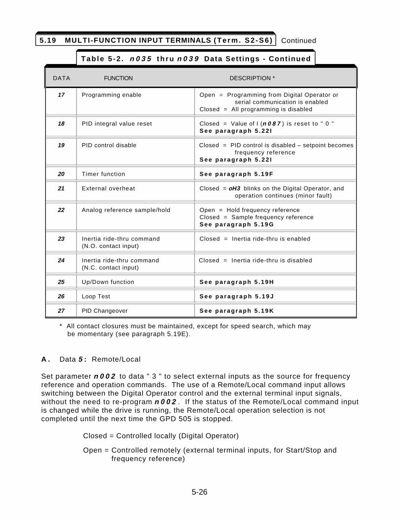
Continued
* All contact closures must be maintained, except for speed search, which may be momentary (see paragraph 5.19E).
A . Data 5 : Remote/Local
Set parameter n 0 0 2 to data " 3 " to select external inputs as the source for frequencyreference and operation commands. The use of a Remote/Local command input allowsswitching between the Digital Operator control and the external terminal input signals,without the need to re-program n 0 0 2 . If the status of the Remote/Local command inputis changed while the drive is running, the Remote/Local operation selection is notcompleted until the next time the GPD 505 is stopped.
Closed = Controlled locally (Digital Operator)
Open = Controlled remotely (external terminal inputs, for Start/Stop and frequency reference)
DESCRIPTIONDATA FUNCTION Signal Levels: 0 = state; 1 = pulse
17 Programming enable Open = Programming from Digital Operator or serial communication is enabled
Closed = All programming is disabled
18 PID integral value reset Closed = Value of I (n 0 8 7 ) is reset to " 0 "S e e p a r a g r a p h 5 . 2 2 I
19 PID control disable Closed = PID control is disabled – setpoint becomes frequency reference
S e e p a r a g r a p h 5 . 2 2 I
20 Timer function S e e p a r a g r a p h 5 . 1 9 F
21 External overheat Closed = oH3 blinks on the Digital Operator, and operation continues (minor fault)
22 Analog reference sample/hold Open = Hold frequency referenceClosed = Sample frequency referenceS e e p a r a g r a p h 5 . 1 9 G
23 Inertia ride-thru command Closed = Inertia ride-thru is enabled(N.O. contact input)
24 Inertia ride-thru command Closed = Inertia ride-thru is disabled(N.C. contact input)
25 Up/Down function S e e p a r a g r a p h 5 . 1 9 H
26 Loop Test S e e p a r a g r a p h 5 . 1 9 J
27 PID Changeover S e e p a r a g r a p h 5 . 1 9 K
DATA FUNCTION DESCRIPTION *
T a b l e 5 - 2 . n 0 3 5 t h r u n 0 3 9 Data Sett ings - Continued
5-26
5.19 MULTI-FUNCTION INPUT TERMINALS ( T e r m . S 2 - S 6 )
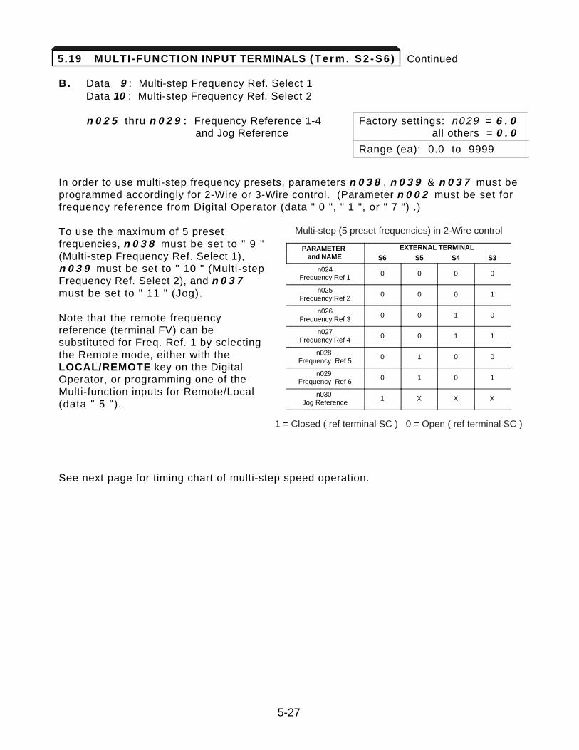
Continued
B. Data 9 : Multi-step Frequency Ref. Select 1Data 10 : Multi-step Frequency Ref. Select 2
n 0 2 5 thru n 0 2 9 : Frequency Reference 1-4 Factory settings: n029 = 6 . 0and Jog Reference all others = 0 . 0
Range (ea): 0.0 to 9999
In order to use multi-step frequency presets, parameters n 0 3 8 , n 0 3 9 & n 0 3 7 must beprogrammed accordingly for 2-Wire or 3-Wire control. (Parameter n 0 0 2 must be set forfrequency reference from Digital Operator (data " 0 ", " 1 ", or " 7 ") .)
To use the maximum of 5 presetfrequencies, n 0 3 8 must be set to " 9 "(Multi-step Frequency Ref. Select 1),n 0 3 9 must be set to " 10 " (Multi-stepFrequency Ref. Select 2), and n 0 3 7must be set to " 11 " (Jog).
Note that the remote frequencyreference (terminal FV) can besubstituted for Freq. Ref. 1 by selectingthe Remote mode, either with theLOCAL/REMOTE key on the DigitalOperator, or programming one of theMulti-function inputs for Remote/Local(data " 5 ").
See next page for timing chart of multi-step speed operation.
5-27
PARAMETERand NAME
EXTERNAL TERMINAL
S6 S5 S4 S3
n024Frequency Ref 1
0 0 0 0
n025Frequency Ref 2
0 0 0 1
n026Frequency Ref 3
0 0 1 0
n027Frequency Ref 4
0 0 1 1
n028Frequency Ref 5
0 1 0 0
n029Frequency Ref 6
0 1 0 1
n030Jog Reference
1 X X X
1 = Closed ( ref terminal SC ) 0 = Open ( ref terminal SC )
Multi-step (5 preset frequencies) in 2-Wire control
5.19 MULTI-FUNCTION INPUT TERMINALS ( T e r m . S 2 - S 6 )
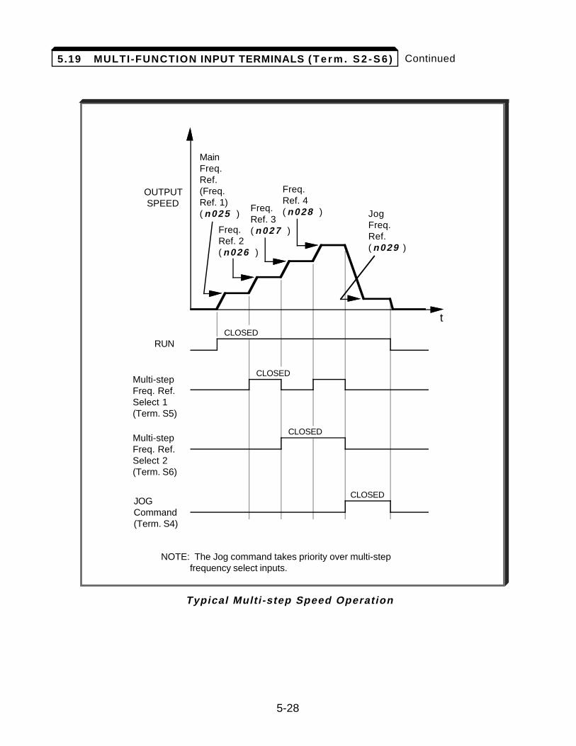
5-28
Continued
Typical Multi-step Speed Operation
t
OUTPUT SPEED
RUN
MainFreq.Ref.(Freq.Ref. 1)( n025 )
Freq.Ref. 2( n026 )
JogFreq.Ref.( n029 )
Multi-stepFreq. Ref.Select 1(Term. S5)
Multi-stepFreq. Ref.Select 2(Term. S6)
JOGCommand(Term. S4)
CLOSED
CLOSED
CLOSED
CLOSED
Freq.Ref. 3( n027 )
Freq.Ref. 4( n028 )
NOTE: The Jog command takes priority over multi-step frequency select inputs.
5.19 MULTI-FUNCTION INPUT TERMINALS ( T e r m . S 2 - S 6 )
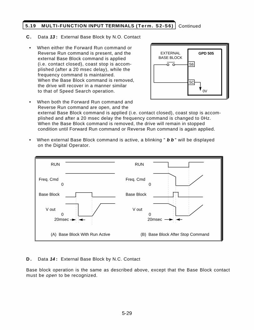
Continued
C. Data 13 : External Base Block by N.O. Contact
• When either the Forward Run command or Reverse Run command is present, and the external Base Block command is applied (i.e. contact closed), coast stop is accom-plished (after a 20 msec delay), while the frequency command is maintained. When the Base Block command is removed, the drive will recover in a manner similar to that of Speed Search operation.
• When both the Forward Run command and Reverse Run command are open, and the external Base Block command is applied (i.e. contact closed), coast stop is accom-plished and after a 20 msec delay the frequency command is changed to 0Hz. When the Base Block command is removed, the drive will remain in stopped condition until Forward Run command or Reverse Run command is again applied.
• When external Base Block command is active, a blinking " b b " will be displayed on the Digital Operator.
D . Data 14 : External Base Block by N.C. Contact
Base block operation is the same as described above, except that the Base Block contactmust be open to be recognized.
5-29
GPD 505
S6
SC
0V
EXTERNALBASE BLOCK
o o
RUN RUN
Freq. Cmd Freq. Cmd0 0
Base Block Base Block
V out V out0 0
20msec 20msec
(A) Base Block With Run Active (B) Base Block After Stop Command
5.19 MULTI-FUNCTION INPUT TERMINALS ( T e r m . S 2 - S 6 )
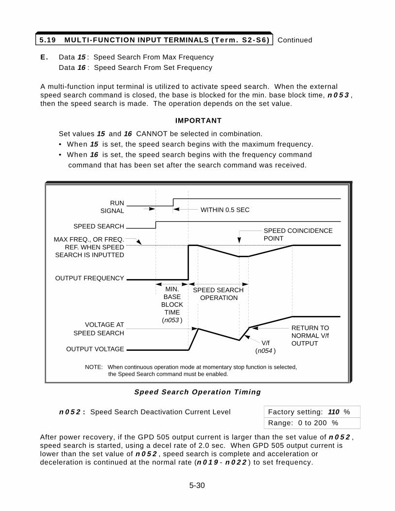
Continued
E. Data 15 : Speed Search From Max Frequency
Data 16 : Speed Search From Set Frequency
A multi-function input terminal is utilized to activate speed search. When the externalspeed search command is closed, the base is blocked for the min. base block time, n 0 5 3 ,then the speed search is made. The operation depends on the set value.
IMPORTANT
Set values 15 and 16 CANNOT be selected in combination.
• When 15 is set, the speed search begins with the maximum frequency.
• When 16 is set, the speed search begins with the frequency command
command that has been set after the search command was received.
n 0 5 2 : Speed Search Deactivation Current Level Factory setting: 110 %
Range: 0 to 200 %
After power recovery, if the GPD 505 output current is larger than the set value of n 0 5 2 ,speed search is started, using a decel rate of 2.0 sec. When GPD 505 output current islower than the set value of n 0 5 2 , speed search is complete and acceleration ordeceleration is continued at the normal rate (n 0 1 9 - n 0 2 2 ) to set frequency.
RUNSIGNAL
SPEED SEARCH
MAX FREQ., OR FREQ.REF. WHEN SPEED
SEARCH IS INPUTTED
OUTPUT FREQUENCY
VOLTAGE ATSPEED SEARCH
OUTPUT VOLTAGE
MIN.BASE
BLOCKTIME
(n053 )
V/f(n054 )
SPEED SEARCHOPERATION
WITHIN 0.5 SEC
NOTE: When continuous operation mode at momentary stop function is selected,the Speed Search command must be enabled.
Speed Search Operation Timing
5-30
SPEED COINCIDENCEPOINT
RETURN TO NORMAL V/fOUTPUT
5.19 MULTI-FUNCTION INPUT TERMINALS ( T e r m . S 2 - S 6 )
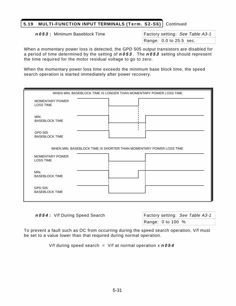
Continued
n 0 5 3 : Minimum Baseblock Time Factory setting: See Table A3-1
Range: 0.0 to 25.5 sec.
When a momentary power loss is detected, the GPD 505 output transistors are disabled fora period of time determined by the setting of n 0 5 3 . The n 0 5 3 setting should representthe time required for the motor residual voltage to go to zero.
When the momentary power loss time exceeds the minimum base block time, the speedsearch operation is started immediately after power recovery.
n 0 5 4 : V/f During Speed Search Factory setting: See Table A3-1
Range: 0 to 100 %
To prevent a fault such as OC from occurring during the speed search operation, V/f mustbe set to a value lower than that required during normal operation.
V/f during speed search = V/f at normal operation x n 0 5 4
5-31
WHEN MIN. BASEBLOCK TIME IS LONGER THAN MOMENTARY POWER LOSS TIME
MOMENTARY POWERLOSS TIME
MIN.BASEBLOCK TIME
GPD 505BASEBLOCK TIME
WHEN MIN. BASEBLOCK TIME IS SHORTER THAN MOMENTARY POWER LOSS TIME
MOMENTARY POWERLOSS TIME
MIN.BASEBLOCK TIME
GPD 505BASEBLOCK TIME
5.19 MULTI-FUNCTION INPUT TERMINALS ( T e r m . S 2 - S 6 )
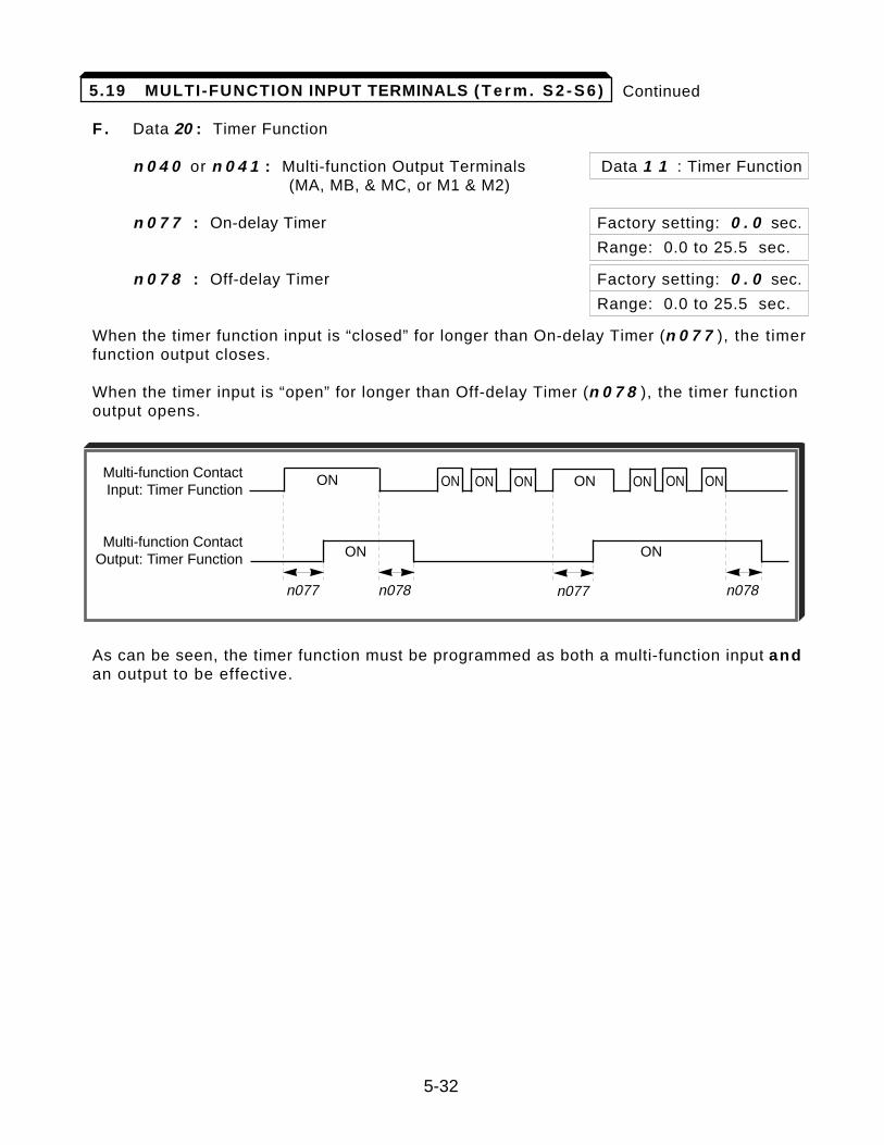
Continued
F . Data 20 : Timer Function
n 0 4 0 or n 0 4 1 : Multi-function Output Terminals Data 1 1 : Timer Function(MA, MB, & MC, or M1 & M2)
n 0 7 7 : On-delay Timer Factory setting: 0 . 0 sec.
Range: 0.0 to 25.5 sec.
n 0 7 8 : Off-delay Timer Factory setting: 0 . 0 sec.
Range: 0.0 to 25.5 sec.
When the timer function input is “closed” for longer than On-delay Timer (n 0 7 7 ), the timerfunction output closes.
When the timer input is “open” for longer than Off-delay Timer (n 0 7 8 ), the timer functionoutput opens.
As can be seen, the timer function must be programmed as both a multi-function input andan output to be effective.
5-32
5.19 MULTI-FUNCTION INPUT TERMINALS (T e r m . S 2 - S 6 )
Multi-function ContactInput: Timer Function
Multi-function ContactOutput: Timer Function
n077 n078
ON
ON ON
ON
n077
ONON ON
n078
ON ON ON
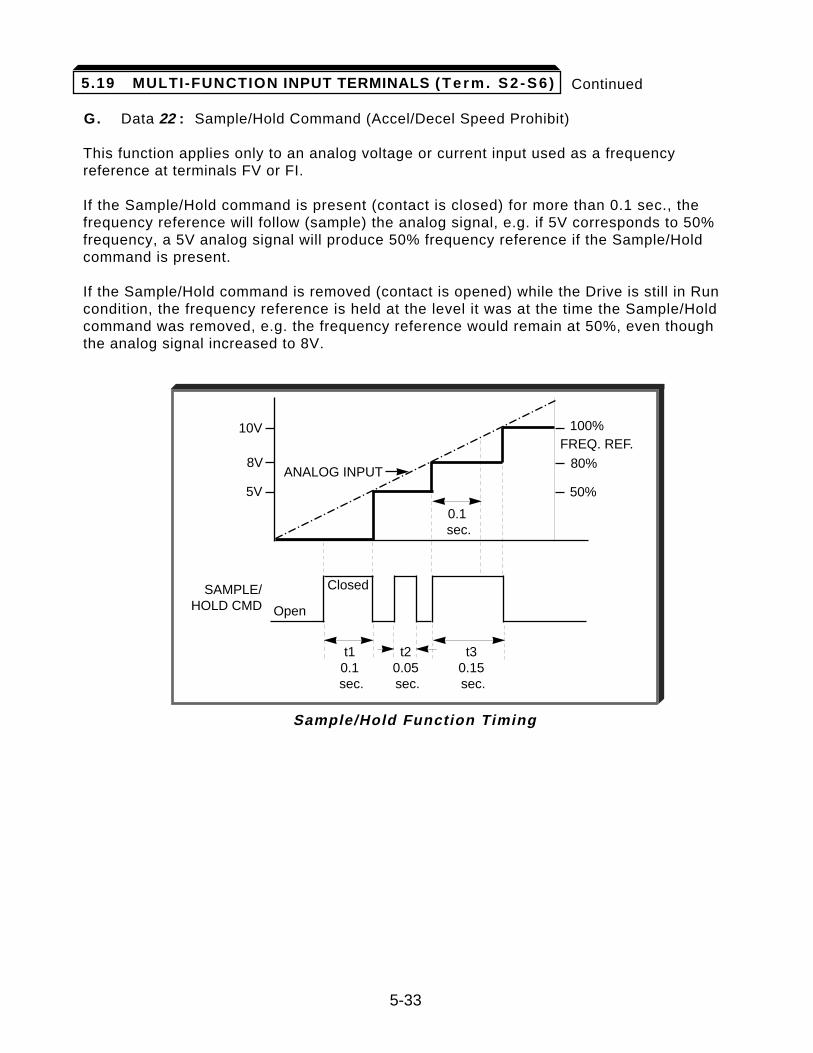
5-33
Continued
G. Data 22 : Sample/Hold Command (Accel/Decel Speed Prohibit)
This function applies only to an analog voltage or current input used as a frequencyreference at terminals FV or FI.
If the Sample/Hold command is present (contact is closed) for more than 0.1 sec., thefrequency reference will follow (sample) the analog signal, e.g. if 5V corresponds to 50%frequency, a 5V analog signal will produce 50% frequency reference if the Sample/Holdcommand is present.
If the Sample/Hold command is removed (contact is opened) while the Drive is still in Runcondition, the frequency reference is held at the level it was at the time the Sample/Holdcommand was removed, e.g. the frequency reference would remain at 50%, even thoughthe analog signal increased to 8V.
Sample/Hold Function Timing
SAMPLE/HOLD CMD
FREQ. REF.
Open
10V 100%
80%
50%
8V
5V
t10.1sec.
0.1sec.
t2 0.05sec.
t30.15sec.
Closed
ANALOG INPUT
5.19 MULTI-FUNCTION INPUT TERMINALS ( T e r m . S 2 - S 6 )
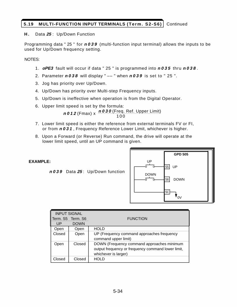
Continued
H . Data 25 : Up/Down Function
Programming data " 25 " for n 0 3 9 (multi-function input terminal) allows the inputs to beused for Up/Down frequency setting.
NOTES:
1. oPE3 fault will occur if data " 25 " is programmed into n 0 3 5 thru n 0 3 8 .
2. Parameter n 0 3 8 will display " –– " when n 0 3 9 is set to " 25 ".
3. Jog has priority over Up/Down.
4. Up/Down has priority over Multi-step Frequency inputs.
5. Up/Down is ineffective when operation is from the Digital Operator.
6. Upper limit speed is set by the formula:
n 0 1 2 (Fmax) x n 0 3 0 (Freq. Ref. Upper Limit)1 0 0
7. Lower limit speed is either the reference from external terminals FV or FI,or from n 0 3 1 , Frequency Reference Lower Limit, whichever is higher.
8. Upon a Forward (or Reverse) Run command, the drive will operate at thelower limit speed, until an UP command is given.
EXAMPLE:
n 0 3 9 Data 25 : Up/Down function
5-34
GPD 505
S5 UP
S6 DOWN
SC
0V
UPo o
DOWNo o
INPUT SIGNALTerm. S5 Term. S6 FUNCTION
UP DOWNOpen Open HOLDClosed Open UP (Frequency command approaches frequency
command upper limit)Open Closed DOWN (Frequency command approaches minimum
output frequency or frequency command lower limit,whichever is larger)
Closed Closed HOLD
5.19 MULTI-FUNCTION INPUT TERMINALS ( T e r m . S 2 - S 6 )
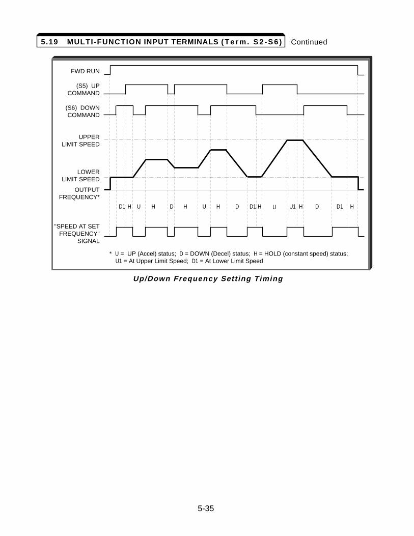
Continued
5-35
FWD RUN
(S5) UPCOMMAND
(S6) DOWNCOMMAND
UPPERLIMIT SPEED
LOWERLIMIT SPEED
OUTPUT FREQUENCY*
"SPEED AT SETFREQUENCY"
SIGNAL
* U = UP (Accel) status; D = DOWN (Decel) status; H = HOLD (constant speed) status;U1 = At Upper Limit Speed; D1 = At Lower Limit Speed
Up/Down Frequency Sett ing Timing
D1 D D DH H H H H H HU1U U UD1 D1
5.19 MULTI-FUNCTION INPUT TERMINALS ( T e r m . S 2 - S 6 )
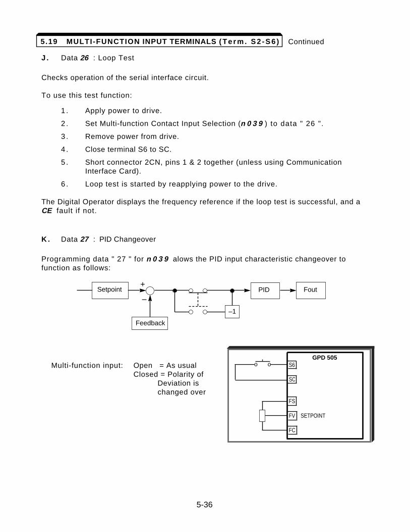
Continued
J . Data 26 : Loop Test
Checks operation of the serial interface circuit.
To use this test function:
1 . Apply power to drive.
2 . Set Multi-function Contact Input Selection (n 0 3 9 ) to data " 26 ".
3 . Remove power from drive.
4 . Close terminal S6 to SC.
5 . Short connector 2CN, pins 1 & 2 together (unless using Communication Interface Card).
6 . Loop test is started by reapplying power to the drive.
The Digital Operator displays the frequency reference if the loop test is successful, and aCE fault if not.
K . Data 27 : PID Changeover
Programming data " 27 " for n 0 3 9 alows the PID input characteristic changeover tofunction as follows:
Multi-function input: Open = As usualClosed = Polarity of
Deviation is changed over
5-36
5.19 MULTI-FUNCTION INPUT TERMINALS ( T e r m . S 2 - S 6 )
GPD 505S6
SC
FS
FV SETPOINT
FC
o o
Setpoint PID Fout
Feedback
–1
+
–
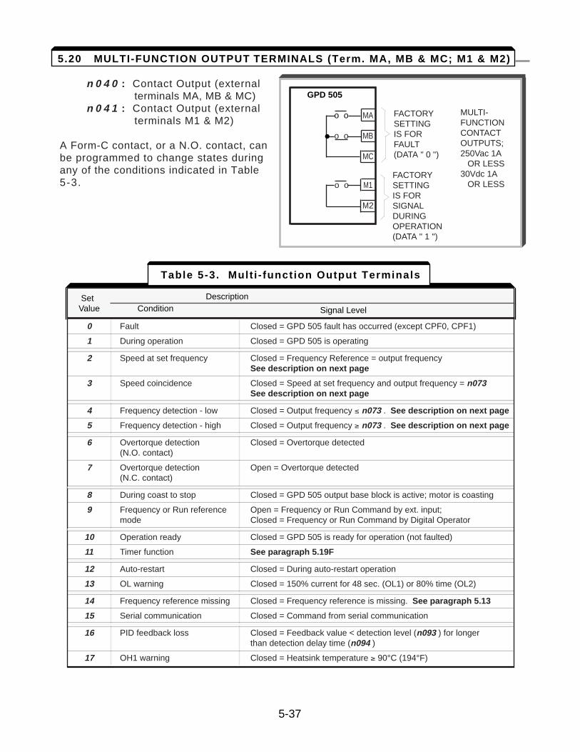
n 0 4 0 : Contact Output (external terminals MA, MB & MC)
n 0 4 1 : Contact Output (external terminals M1 & M2)
A Form-C contact, or a N.O. contact, canbe programmed to change states duringany of the conditions indicated in Table 5-3.
GPD 505
o o MA
o o MB
MC
o o M1
M2
FACTORY SETTINGIS FOR SIGNALDURING OPERATION(DATA " 1 ")
FACTORY SETTINGIS FOR FAULT(DATA " 0 ")
MULTI-FUNCTIONCONTACT OUTPUTS; 250Vac 1A
OR LESS30Vdc 1A
OR LESS
Set DescriptionValue Name Signal Level
0 Fault Closed = GPD 505 fault has occurred (except CPF0, CPF1)
1 During operation Closed = GPD 505 is operating
2 Speed at set frequency Closed = Frequency Reference = output frequencySee description on next page
3 Speed coincidence Closed = Speed at set frequency and output frequency = n073See description on next page
4 Frequency detection - low Closed = Output frequency ² n073 . See description on next page
5 Frequency detection - high Closed = Output frequency ³ n073 . See description on next page
6 Overtorque detection Closed = Overtorque detected(N.O. contact)
7 Overtorque detection Open = Overtorque detected(N.C. contact)
8 During coast to stop Closed = GPD 505 output base block is active; motor is coasting
9 Frequency or Run reference Open = Frequency or Run Command by ext. input; mode Closed = Frequency or Run Command by Digital Operator
10 Operation ready Closed = GPD 505 is ready for operation (not faulted)
11 Timer function See paragraph 5.19F
12 Auto-restart Closed = During auto-restart operation
13 OL warning Closed = 150% current for 48 sec. (OL1) or 80% time (OL2)
14 Frequency reference missing Closed = Frequency reference is missing. See paragraph 5.13
15 Serial communication Closed = Command from serial communication
16 PID feedback loss Closed = Feedback value < detection level (n093 ) for longer than detection delay time (n094 )
17 OH1 warning Closed = Heatsink temperature ³ 90°C (194°F)
Set DescriptionValue Condition Signal Level
Table 5-3. Mult i - function Output Terminals
5-37
5.20 MULTI-FUNCTION OUTPUT TERMINALS (Term. MA, MB & MC; M1 & M2)
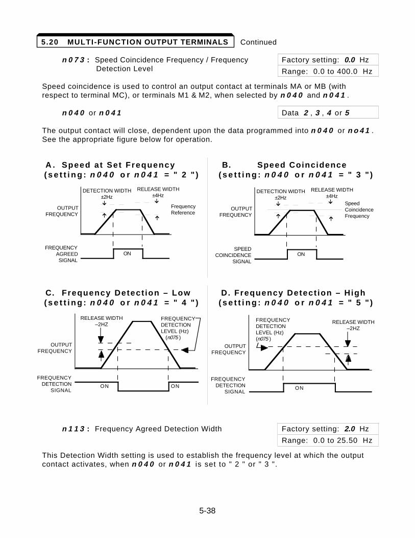
Continued
n 0 7 3 : Speed Coincidence Frequency / Frequency Factory setting: 0.0 HzDetection Level Range: 0.0 to 400.0 Hz
Speed coincidence is used to control an output contact at terminals MA or MB (withrespect to terminal MC), or terminals M1 & M2, when selected by n 0 4 0 and n 0 4 1 .
n 0 4 0 or n 0 4 1 Data 2 , 3 , 4 or 5
The output contact will close, dependent upon the data programmed into n 0 4 0 or n o 4 1 .See the appropriate figure below for operation.
A . Speed at Set Frequency B. Speed Coincidence( s e t t i n g : n 0 4 0 o r n 0 4 1 = " 2 " ) ( s e t t i n g : n 0 4 0 o r n 0 4 1 = " 3 " )
C. Frequency Detect ion – Low D. Frequency Detect ion – High( s e t t i n g : n 0 4 0 o r n 0 4 1 = " 4 " ) ( s e t t i n g : n 0 4 0 o r n 0 4 1 = " 5 " )
n 1 1 3 : Frequency Agreed Detection Width Factory setting: 2.0 Hz
Range: 0.0 to 25.50 Hz
This Detection Width setting is used to establish the frequency level at which the outputcontact activates, when n 0 4 0 or n 0 4 1 is set to " 2 " or " 3 ".
5-38
5.20 MULTI-FUNCTION OUTPUT TERMINALS
FREQUENCYAGREEDSIGNAL
OUTPUTFREQUENCY
ON
FrequencyReference
DETECTION WIDTH±2Hz
RELEASE WIDTH±4Hz
SPEEDCOINCIDENCE
SIGNAL
OUTPUTFREQUENCY
ON
SpeedCoincidenceFrequency
DETECTION WIDTH±2Hz
RELEASE WIDTH±4Hz
OUTPUTFREQUENCY
FREQUENCYDETECTIONLEVEL (Hz) (n075 )
RELEASE WIDTH–2HZ
FREQUENCYDETECTION
SIGNALON ON
OUTPUTFREQUENCY
FREQUENCYDETECTIONLEVEL (Hz)(n075 )
RELEASE WIDTH–2HZ
FREQUENCYDETECTION
SIGNALON
Overtorque detection is used to compare GPD 505 rated output current with theovertorque detection level. When the output current is equal to or greater than thedefined level, an overtorque condition exists. This will be indicated as an oL3 fault on theDigital Operator. This feature can be selected to operate over a wide range of conditions.
A . n 0 7 4 : Overtorque Detection Factory setting: 0
This constant determines whether the overtorque detection function of the GPD 505 isenabled, under what conditions it will detect for overtorque, and what operation it willperform after detecting an overtorque.
Overtorque Operation After Detection Setting Detection Detection Condition
0 Disabled —— ——
1 Enabled Continues Only at set frequency
2 Enabled Continues At all times except during stop-ping or DC injection braking
3 Enabled Coast to stop Only at set frequency
4 Enabled Coast to stop At all times except during stop-ping or DC injection braking
— For overtorque detection during accel or decel, set to " 2 " or " 4 ".— For continuous operation after overtorque detection, set to " 1 " or
" 2 ". During detection, the Digital Operator displays and “ o L 3 ” alarm (bl inking).
— To stop the drive at an overtorque detection fault, set to " 3 " or " 4 ". At detection, the Digital Operator displays an " o L 3 " fau l t .
— To output an overtorque detection signal, set output terminal function select ion (n 4 0 or n 4 1 ) to " 6 " or " 7 ".
B. n 0 7 5 : Overtorque Detection Level Factory setting: 160 %
Range: 30 to 200 %
This is the reference point for determining that an overtorque condition exists. Set as apercent of GPD 505 rated current (see Appendix 2).
C. n 0 7 6 : Overtorque Detection Time Factory setting: 0.1 sec.
Range: 0.0 to 10.0 seconds
Determines how long an overtorque condition must exist before another event will occur,e.g. coast to stop, multi-function output change of state, or o L 3 warning or fault display.
5-39
5.21 OVERTORQUE DETECTION
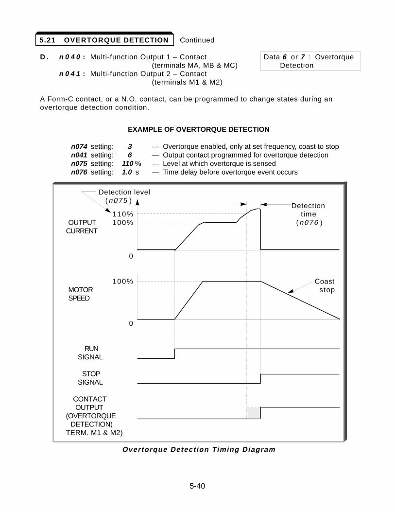
Continued
D . n 0 4 0 : Multi-function Output 1 – Contact Data 6 or 7 : Overtorque(terminals MA, MB & MC) Detection
n 0 4 1 : Multi-function Output 2 – Contact (terminals M1 & M2)
A Form-C contact, or a N.O. contact, can be programmed to change states during anovertorque detection condition.
EXAMPLE OF OVERTORQUE DETECTION
n074 setting: 3 — Overtorque enabled, only at set frequency, coast to stopn041 setting: 6 — Output contact programmed for overtorque detectionn075 setting: 110 % — Level at which overtorque is sensedn076 setting: 1.0 s — Time delay before overtorque event occurs
Detection level(n075 )
Detection110% time
OUTPUT 100% (n076 )CURRENT
0
100% CoastMOTOR stopSPEED
0
RUNSIGNAL
STOPSIGNAL
CONTACTOUTPUT
(OVERTORQUEDETECTION)
TERM. M1 & M2)
Overtorque Detection Timing Diagram
5-40
5.21 OVERTORQUE DETECTION
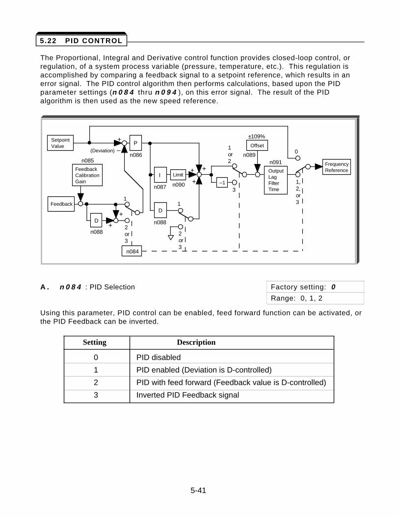
The Proportional, Integral and Derivative control function provides closed-loop control, orregulation, of a system process variable (pressure, temperature, etc.). This regulation isaccomplished by comparing a feedback signal to a setpoint reference, which results in anerror signal. The PID control algorithm then performs calculations, based upon the PIDparameter settings (n 0 8 4 thru n 0 9 4 ), on this error signal. The result of the PIDalgorithm is then used as the new speed reference.
A . n 0 8 4 : PID Selection Factory setting: 0
Range: 0, 1, 2
Using this parameter, PID control can be enabled, feed forward function can be activated, orthe PID Feedback can be inverted.
Setting Description
0 PID disabled
1 PID enabled (Deviation is D-controlled)
2 PID with feed forward (Feedback value is D-controlled)
3 Inverted PID Feedback signal
5-41
5.22 PID CONTROL
SetpointValue
(Deviation)
Feedback
FeedbackCalibrationGain
n085
D+
–
+
1
2or3
+
n088
P
n086
I
n087
D
n088
1
2or3
n084
Limit
n090
++
+
±109%
Offset
n089
OutputLagFilterTime
n091
0
1,2,or3
FrequencyReference
3–1
1or2
Continued
B. Setpoint Reference Selection
n 0 0 2 : Operation Mode Selection Factory setting: 3
Range: 0 to 8
n 0 4 2 : Auto Analog Input Selection Factory setting: 0
Range: 0 or 1
n 0 2 5 thru n 0 2 9 : Multi-step Frequency Presets Factory settings: n029 = 6 . 0all others = 0 . 0
Range (ea): 0.0 to 9999
Select the PID control Setpoint Reference from either the external terminal FV (for 0-10VDC), or from multi-step speed parameters, n 0 2 5 thru n 0 2 9 .
• External terminal FV: Set n 0 0 2 to data " 2 " or " 3 ".• Multi-step speed parameters: Set n 0 0 2 to data " 0 " or " 1 ". (See Operation
Mode Selection, page A1-1, and Multi-step Speed Setting, paragraph 5.19B.)
C. Feedback Signal Selection
n 0 4 3 : Manual Analog Input Selection Factory setting: 1
Range: 0 or 1
Select the PID control Feedback Signal from external terminal FI for either a current signal(4-20mA DC) or a voltage (0-10 VDC).
• Current signal: Set n 0 4 3 to data " 1 ".• Voltage signal: Set n 0 4 3 to data " 0 ".
( Must also cut jumper J1 on Control PCB. )
D . Inverse PID
NOTE: The following applies only when n 0 8 4 = " 3 ".
If using inverse PID control (n 0 8 4 = "3"), the following adjustments need to be made:
• If a 0-10 VDC reference is used to determine the setpoint, exchange the values in n 0 4 6 and n 0 4 7 .
EXAMPLE: If the Frequency Reference Gain (n 0 4 6 ) = " 100 " % and the Frequency Reference Bias (n 0 4 7 ) = " 0 " %, these parameters will now need to be set as follows:
n 0 4 6 = " 0 " % n 0 4 7 = " 100 " %
5-42
5.22 PID CONTROL
Continued
• If the setpoint is entered via the keypad, the entered setpoint needs to be recalculated as follows:
Entered Setpoint = Max Value (n024 ) – Desired Setpoint
This effectively inverts the reference input.
EXAMPLE: Desired Setpoint is 43.0 Hz, Max. Value (n 0 2 4 ) = " 60.0 " Hz. Therefore, the entered setpoint is:
Entered Setpoint = 60.0 Hz – 43.0 Hz = " 17.0 " Hz.
This setpoint should be entered as " 17.0 " Hz.
• If PID feedback loss detection is used, the inverse of the desired feedback loss detection level should be entered in n 0 9 3 .
EXAMPLE: Deseired Feedback Loss Level = 7%.
Desired Fdbk Loss Det. Level = 100% – 7% = " 93 " %.
E. n 0 8 5 : Feedback Calibration Gain Factory setting: 1 . 0 0
Range: 0.00 to 10.00
This parameter is used to adjust the Feedback Signal level.
F . Feedback Loss Detection
n 0 9 2 : Feedback Loss Detection Selection Factory setting: 0
Range: 0 or 1
n 0 9 3 : Feedback Loss Detection Level Factory setting: 0 %
Range: 0 to 100 %
n 0 9 4 : Feedback Loss Detection Delay Time Factory setting: 1 . 0 seconds
Range: 0.0 to 25.5 seconds
When enabled (n 0 9 2 = data " 1 "), the drive will sense if the Feedback Signal falls belowthe n 0 9 3 level for more than the n 0 9 4 delay time.
G. PID Sett ings
n 0 8 6 : Proportional Gain Factory setting: 1 . 0
Range: 0.0 to 10.0
Proportional gain is the value by which the error signal is multiplied to generate the new speed reference.
(continued on next page)
5-43
5.22 PID CONTROL
Continued
n 0 8 7 : Integral Time Factory setting: 1 0 . 0 seconds
Range: 0.0 to 100.0 seconds
This parameter determines now fast the integral gain increase is added to the control loop.
n 0 8 8 : Derivative Time Factory setting: 0 . 0 seconds
Range: 0.00 to 1.00 seconds
Derivative time can be adjusted to dampen initial oscillations and reduce overshoot, which serves to improve stability.
These parameters are all interactive, and will need to be adjusted until the control loop isproperly tuned, i.e. stable with minimal stead-state error. A general procedure for tuningthese parameters is as follows:
1 . Adjust Proportional Gain until continuous oscillations in the Controlled Variable are at a minimum.
2 . The addition of Integral Time will cause the steady-state error to approach zero. The time should be adjusted so that this minimal error is attained as fast as possible, without making the system oscillate.
3 . If necessary, adjust derivative time to reduce overshoot during startup. The drive’s accel and decel rate times can also be used for this purpose.
H . n 0 8 9 : Offset Factory setting: 0 %
Range: –109 to 109 %
n 0 9 0 : Integral Value Limit Factory setting: 1 0 0 %
Range: 0 to 109 %
n 0 9 1 : Output Lag Filter Time Factory setting: 0 . 0 seconds
Range: 0.00 to 1.00 seconds
These parameters are factory set for optimum results for most applications, and generallydon’t need to be changed. The offset value (n 0 8 9 ) provides a bias for the PID value. Ifthe control system oscillates and cannot be dampened by adjusting the Integral Time(n 0 8 7 ), decrease the value of n 0 9 0 or change the value of n 0 9 1 .
I . n 0 3 5 thru n 0 3 9 : Multi-function Input Terminals
Data 1 8 : Integral Value Reset
A Multi-function Input Terminal can be used to reset the value of n 0 8 7 to data " 0 ".Note that this value is also reset to " 0 " if the drive is given a STOP command.
Data 1 9 : PID Disable
A Multi-function Input Terminal can be used to disable PID control. When this terminal is closed, PID control is disabled, and the Setpoint Reference is used as the frequency reference.
5-44
5.22 PID CONTROL
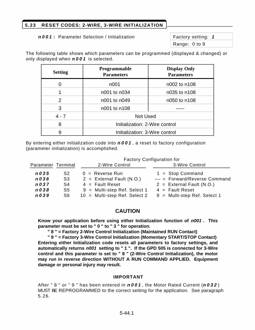
n 0 0 1 : Parameter Selection / Initialization Factory setting: 1
Range: 0 to 9
The following table shows which parameters can be programmed (displayed & changed) oronly displayed when n 0 0 1 is selected.
Programmable Display Only Setting Parameters Parameters
0 n001 n002 to n108
1 n001 to n034 n035 to n108
2 n001 to n049 n050 to n108
3 n001 to n108 –––
4 - 7 Not Used
8 Initialization: 2-Wire control
9 Initialization: 3-Wire control
By entering either initialization code into n 0 0 1 , a reset to factory configuration(parameter initialization) is accomplished.
Factory Configuration forParameter Terminal 2-Wire Control 3-Wire Control
n 0 3 5 S2 0 = Reverse Run 1 = Stop Commandn 0 3 6 S3 2 = External Fault (N.O.) –– = Forward/Reverse Commandn 0 3 7 S4 4 = Fault Reset 2 = External Fault (N.O.)n 0 3 8 S5 9 = Multi-step Ref. Select 1 4 = Fault Resetn 0 3 9 S6 10 = Multi-step Ref. Select 2 9 = Multi-step Ref. Select 1
CAUTION
Know your application before using either Initialization function of n001 . Thisparameter must be set to " 0 " to " 3 " for operation.
" 8 " = Factory 2-Wire Control Initialization (Maintained RUN Contact)" 9 " = Factory 3-Wire Control Initialization (Momentary START/STOP Contact)
Entering either Initialization code resets all parameters to factory settings, andautomatically returns n001 setting to " 1 ". If the GPD 505 is connected for 3-Wirecontrol and this parameter is set to " 8 " (2-Wire Control Initialization), the motormay run in reverse direction WITHOUT A RUN COMMAND APPLIED. Equipmentdamage or personal injury may result.
IMPORTANT
After " 8 " or " 9 " has been entered in n 0 0 1 , the Motor Rated Current (n 0 3 2 ) MUST BE REPROGRAMMED to the correct setting for the application. See paragraph 5.26.
5-44.1
5.23 RESET CODES: 2-WIRE, 3-WIRE INITIALIZATION
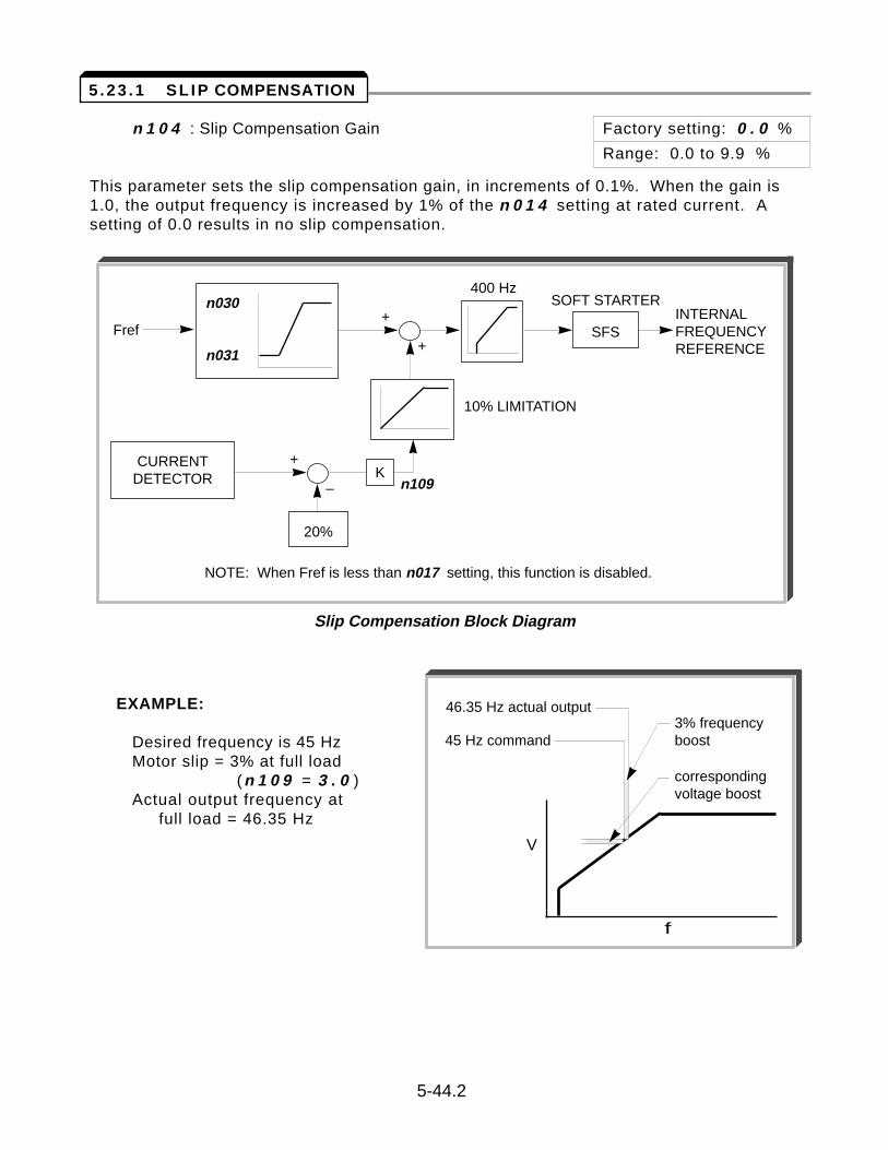
n 1 0 4 : Slip Compensation Gain Factory setting: 0 . 0 %
Range: 0.0 to 9.9 %
This parameter sets the slip compensation gain, in increments of 0.1%. When the gain is1.0, the output frequency is increased by 1% of the n 0 1 4 setting at rated current. Asetting of 0.0 results in no slip compensation.
EXAMPLE:
Desired frequency is 45 HzMotor slip = 3% at full load
(n 1 0 9 = 3 . 0 )Actual output frequency at
full load = 46.35 Hz
5-44.2
5 .23 .1 SL IP COMPENSATION
Fref
n030
n031
+
+
–
+
400 Hz
SFS
SOFT STARTER
10% LIMITATION
n109
INTERNALFREQUENCYREFERENCE
20%
KCURRENT
DETECTOR
NOTE: When Fref is less than n017 setting, this function is disabled.
Slip Compensation Block Diagram
V
f
46.35 Hz actual output3% frequencyboost
correspondingvoltage boost
45 Hz command

Continued
n 1 1 1 : Slip Compensation Primary Delay Factory setting: 2 . 0 sec. Time Constant Range: 0.0 to 25.5 sec.
5-45
5 .23 .1 SL IP COMPENSATION
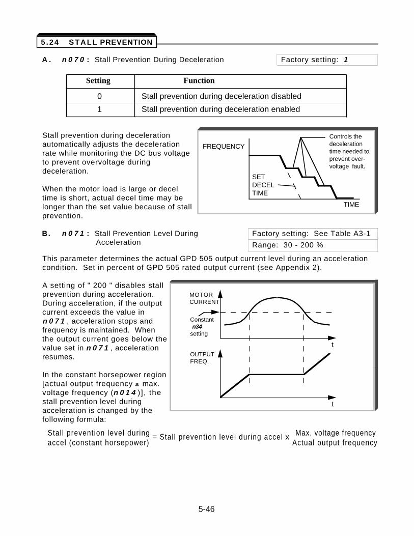
A . n 0 7 0 : Stall Prevention During Deceleration Factory setting: 1
Setting Function
0 Stall prevention during deceleration disabled
1 Stall prevention during deceleration enabled
Stall prevention during decelerationautomatically adjusts the decelerationrate while monitoring the DC bus voltageto prevent overvoltage duringdeceleration.
When the motor load is large or decel time is short, actual decel time may belonger than the set value because of stallprevention.
B. n 0 7 1 : Stall Prevention Level During Factory setting: See Table A3-1 Acceleration Range: 30 - 200 %
This parameter determines the actual GPD 505 output current level during an accelerationcondition. Set in percent of GPD 505 rated output current (see Appendix 2).
A setting of " 200 " disables stallprevention during acceleration.During acceleration, if the outputcurrent exceeds the value inn 0 7 1 , acceleration stops andfrequency is maintained. Whenthe output current goes below thevalue set in n 0 7 1 , accelerationresumes.
In the constant horsepower region[actual output frequency ³ max.voltage frequency (n 0 1 4 ) ] , thestall prevention level duringacceleration is changed by thefollowing formula:
Stal l prevention level during = Stal l prevention level during accel x Max. voltage frequencyaccel (constant horsepower) Actual output frequency
5-46
5 .24 STALL PREVENTION
t
t
MOTORCURRENT
OUTPUTFREQ.
Constant n34setting
TIME
FREQUENCY
SETDECELTIME
Controls thedecelerationtime needed toprevent over-voltage fault.
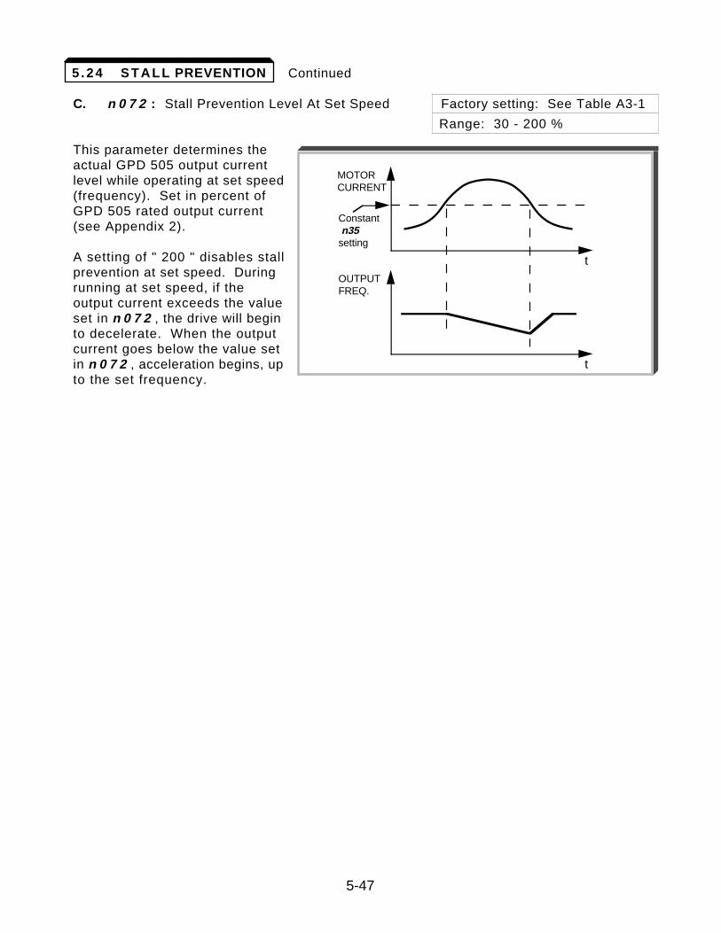
Continued
C. n 0 7 2 : Stall Prevention Level At Set Speed Factory setting: See Table A3-1
Range: 30 - 200 %
This parameter determines theactual GPD 505 output currentlevel while operating at set speed(frequency). Set in percent ofGPD 505 rated output current(see Appendix 2).
A setting of " 200 " disables stallprevention at set speed. Duringrunning at set speed, if theoutput current exceeds the valueset in n 0 7 2 , the drive will beginto decelerate. When the outputcurrent goes below the value setin n 0 7 2 , acceleration begins, upto the set frequency.
5-47
5 .24 STALL PREVENTION
t
t
MOTORCURRENT
OUTPUTFREQ.
Constant n35setting
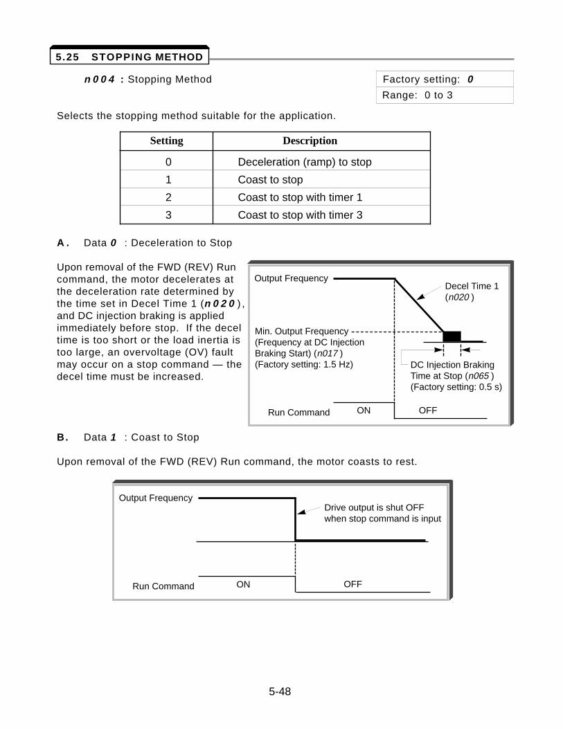
n 0 0 4 : Stopping Method Factory setting: 0
Range: 0 to 3
Selects the stopping method suitable for the application.
Setting Description
0 Deceleration (ramp) to stop
1 Coast to stop
2 Coast to stop with timer 1
3 Coast to stop with timer 3
A . Data 0 : Deceleration to Stop
Upon removal of the FWD (REV) Runcommand, the motor decelerates atthe deceleration rate determined bythe time set in Decel Time 1 (n 0 2 0 ) ,and DC injection braking is appliedimmediately before stop. If the deceltime is too short or the load inertia istoo large, an overvoltage (OV) faultmay occur on a stop command — thedecel time must be increased.
B. Data 1 : Coast to Stop
Upon removal of the FWD (REV) Run command, the motor coasts to rest.
5-48
5.25 STOPPING METHOD
Output Frequency
Run Command ON OFF
Decel Time 1(n020 )
Min. Output Frequency(Frequency at DC InjectionBraking Start) (n017 )(Factory setting: 1.5 Hz) DC Injection Braking
Time at Stop (n065 )(Factory setting: 0.5 s)
Output Frequency
Run Command ON OFF
Drive output is shut OFFwhen stop command is input
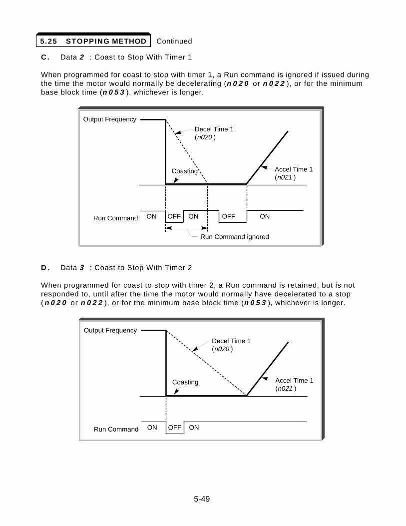
Continued
C. Data 2 : Coast to Stop With Timer 1
When programmed for coast to stop with timer 1, a Run command is ignored if issued duringthe time the motor would normally be decelerating (n 0 2 0 or n 0 2 2 ), or for the minimumbase block time (n 0 5 3 ), whichever is longer.
D . Data 3 : Coast to Stop With Timer 2
When programmed for coast to stop with timer 2, a Run command is retained, but is notresponded to, until after the time the motor would normally have decelerated to a stop(n 0 2 0 or n 0 2 2 ), or for the minimum base block time (n 0 5 3 ), whichever is longer.
5-49
5.25 STOPPING METHOD
Output Frequency
Run Command
Run Command ignored
ON ON ONOFF OFF
Decel Time 1(n020 )
Coasting Accel Time 1(n021 )
Output Frequency
Run Command ON ONOFF
Decel Time 1(n020 )
Coasting Accel Time 1(n021 )
n 0 3 2 : Motor Rated Current Factory setting: See Table A3-1
Range: see description
This parameter should be set, in increments of 0.1 A, to the rated current (FLA) valueshown on the motor nameplate; this value MUST BE between 10% and 120% of the driverated current (refer to Specifications in Appendices 2 & 3 of this manual). If the motorFLA does not fall within this range, a different Model No. drive must be used.
NOTE: Setting n 0 3 2 to " 0.0 " disables the motor overload protection function, regardless of the setting of n 0 3 3 .
n 1 1 0 : No-load Motor Current Factory setting: 3 0 %
Range: 0 to 99 %
n 0 3 3 : Electronic Thermal Motor Protection Factory setting: 1
Range: 0 to 4
Setting Electronic Thermal Characteristics
0 Electronic thermal overload protection disabled
1 General-purpose motor, standard rating (8 min.)
2 General-purpose motor, short-term rating (5 min.)
3 Blower-cooled motor, standard rating (8 min.)
4 Blower-cooled motor, short-term rating (5 min.)
The GPD 505 protects against motor overload with a UL-recognized, built-in electronicthermal overload relay.
The electronic thermal overload function monitors motor temperature, based on driveoutput current and time, to protect the motor from overheating. When the electronicthermal overload trips, an " o L 1 " error occurs, shutting OFF the drive output andpreventing excessive overheating of the motor.
When operating with one drive connected to only one motor, an external thermal relay isnot needed. When operating several motors with one drive, install a thermal overload relayon each motor.
5-50
5.26 THERMAL OVERLOAD PROTECTION
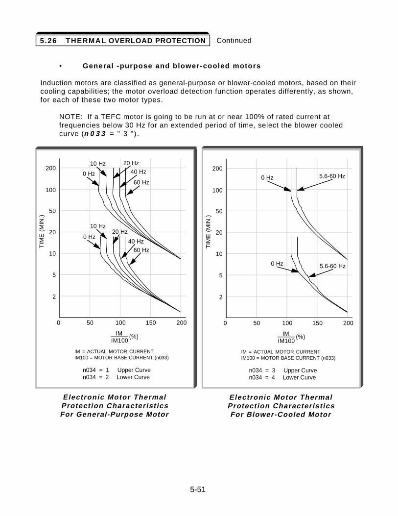
Continued
• General -purpose and blower-cooled motors
Induction motors are classified as general-purpose or blower-cooled motors, based on theircooling capabilities; the motor overload detection function operates differently, as shown,for each of these two motor types.
NOTE: If a TEFC motor is going to be run at or near 100% of rated current at frequencies below 30 Hz for an extended period of time, select the blower cooled curve (n 0 3 3 = " 3 ") .
5-51
0 50 100 150 200
200
100
50
20
10
5
2
TIM
E (
MIN
.)
40 Hz
60 Hz
40 Hz60 Hz
IMIM100
(%)
n034 = 1 Upper Curven034 = 2 Lower Curve
IM = ACTUAL MOTOR CURRENTIM100 = MOTOR BASE CURRENT (n033)
20 Hz10 Hz
0 Hz
10 Hz
0 Hz20 Hz
Electronic Motor Thermal Protection Characteristics For General-Purpose Motor
0 50 100 150 200
200
100
50
20
10
5
2
TIM
E (
MIN
.)
IMIM100
(%)
n034 = 3 Upper Curven034 = 4 Lower Curve
0 Hz 5.6-60 Hz
0 Hz 5.6-60 Hz
IM = ACTUAL MOTOR CURRENTIM100 = MOTOR BASE CURRENT (n033)
Electronic Motor Thermal Protection Characteristics For Blower-Cooled Motor
5.26 THERMAL OVERLOAD PROTECTION
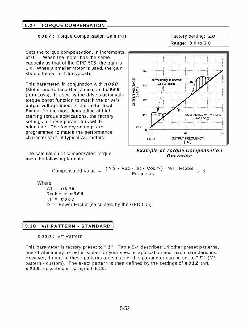
n 0 6 7 : Torque Compensation Gain (KT) Factory setting: 1.0
Range: 0.0 to 3.0
Sets the torque compensation, in incrementsof 0.1. When the motor has the samecapacity as that of the GPD 505, the gain is1.0. When a smaller motor is used, the gainshould be set to 1.5 (typical).
This parameter, in conjunction with n 0 6 8(Motor Line-to-Line Resistance) and n 0 6 9(Iron Loss), is used by the drive’s automatictorque boost function to match the drive’soutput voltage boost to the motor load.Except for the most demanding of highstarting torque applications, the factorysettings of these parameters will beadequate. The factory settings areprogrammed to match the performancecharacteristics of typical AC motors.
The calculation of compensated torque uses the following formula:
( Ã 3 • Vac • Iac • Cos F ) – WI – RcableCompensated Value ÅFrequency
x KT
WhereWI = n 0 6 9Rcable = n 0 6 8KT = n 0 6 7F = Power Factor (calculated by the GPD 505)
n 0 1 0 : V/f Pattern
This parameter is factory preset to " 1 ". Table 5-4 describes 14 other preset patterns,one of which may be better suited for your specific application and load characteristics.However, if none of these patterns are suitable, this parameter can be set to " F " ( V / fpattern - custom). The exact pattern is then defined by the settings of n 0 1 2 thru n 0 1 8 , described in paragraph 5.29.
5-52
OUTPUT FREQUENCY( HZ )
OU
TPU
T V
OLT
AG
E( V
AC
)
460
345
230
115
14 V0
0
1.5 HZ
30 60
PROGRAMMED V/F PATTERN(NO LOAD)
AUTO TORQUE BOOSTV/F PATTERN
Example of Torque CompensationOperation
5.27 TORQUE COMPENSATION
5.28 V / f PATTERN - STANDARD
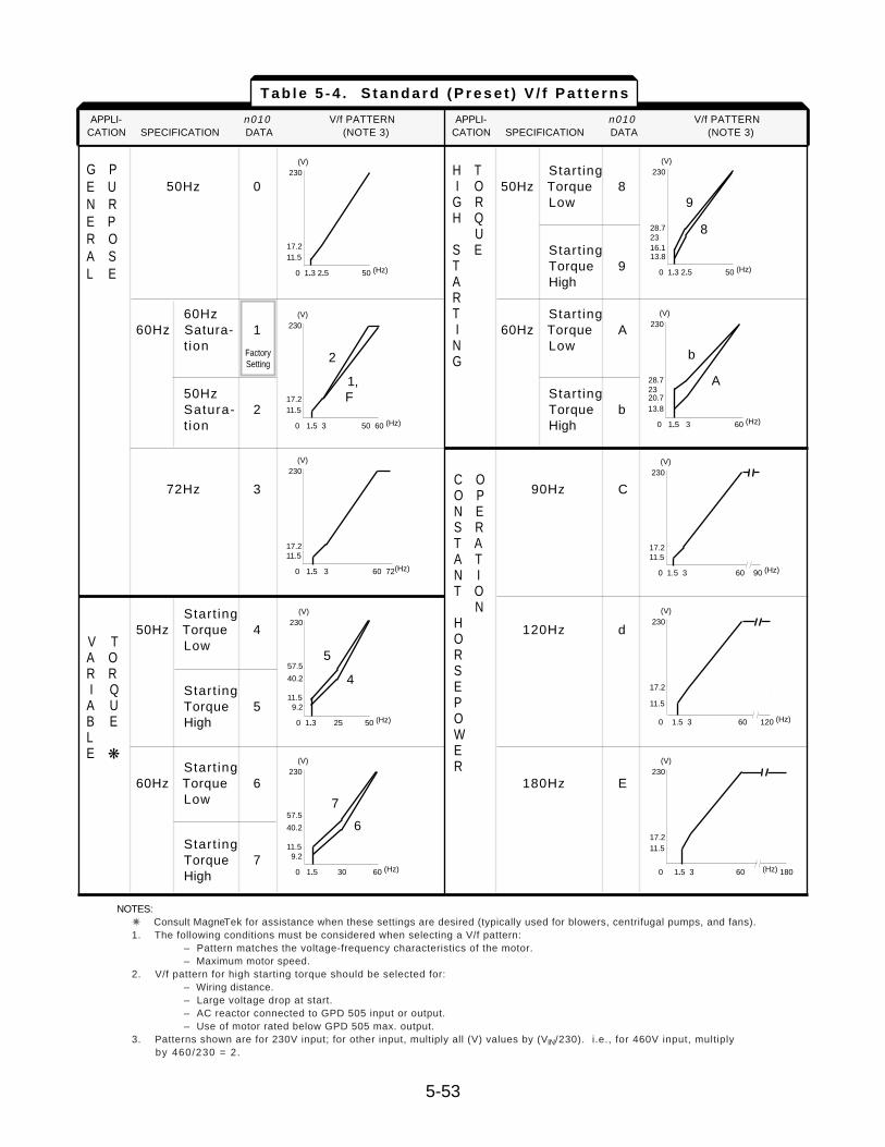
APPLI- Sn-02 V/f PATTERN APPLI- Sn-02 V/f PATTERNCATION SPECIFICATION DATA (NOTE 3) CATION SPECIFICATION DATA (NOTE 3)
Start ing50Hz 0 50Hz Torque 8
Low
Start ingTorque 9High
60Hz Start ing60Hz Satura- 1 60Hz Torque A
tion Low
50Hz Start ingSatura- 2 Torque btion High
72Hz 3 90Hz C
Start ing50Hz Torque 4 120Hz d
Low
Start ingTorque 5High
Start ing60Hz Torque 6 180Hz E
Low
Start ingTorque 7High
NOTES: Consult MagneTek for assistance when these settings are desired (typically used for blowers, centrifugal pumps, and fans).1. The following conditions must be considered when selecting a V/f pattern:
– Pattern matches the voltage-frequency characteristics of the motor.– Maximum motor speed.
2. V/f pattern for high starting torque should be selected for:– Wiring distance.– Large voltage drop at start.– AC reactor connected to GPD 505 input or output.– Use of motor rated below GPD 505 max. output.
3. Patterns shown are for 230V input; for other input, multiply all (V) values by (VIN/230). i.e., for 460V input, multiply by 460/230 = 2.
G PE UN RE PR OA SL E
H TI O
G RH Q
US ETARTI
NG
V TA OR RI QA UB ELE
C OO PN ES RT AA TN IT O
NHORSEPOWER(V)
230
57.5
40.2
11.59.2
0 1.5 30 60 (Hz)
7
6
(V)230
17.211.5
0 1.5 3 60 (Hz) 180
(V)230
17.2
11.5
0 1.5 3 60 120 (Hz)
(V)230
57.5
40.2
11.59.2
0 1.3 25 50 (Hz)
5
4
(V)230
17.211.5
0 1.5 3 60 90 (Hz)
(V)230
17.211.5
0 1.5 3 60 72(Hz)
(V)230
28.723 20.713.8
0 1.5 3 60 (Hz)
b
A
(V)230
28.723 16.113.8
0 1.3 2.5 50 (Hz)
9
8
(V)230
17.211.5
0 1.5 3 50 60 (Hz)
2
1,F
(V)230
17.211.5
0 1.3 2.5 50 (Hz)
APPLI- n010 V/f PATTERN APPLI- n010 V/f PATTERNCATION SPECIFICATION DATA (NOTE 3) CATION SPECIFICATION DATA (NOTE 3)
5-53
T a b l e 5 - 4 . S t a n d a r d ( P r e s e t ) V / f P a t t e r n s
FactorySetting
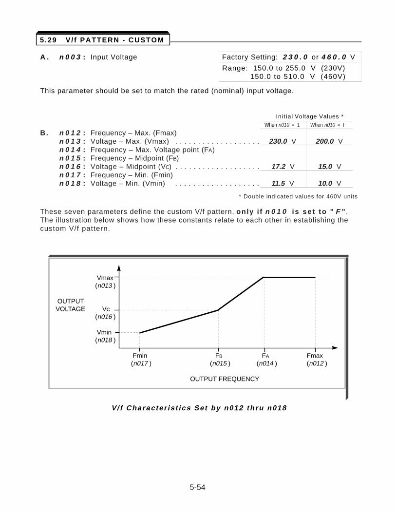
A . n 0 0 3 : Input Voltage Factory Setting: 2 3 0 . 0 or 4 6 0 . 0 V
Range: 150.0 to 255.0 V (230V)150.0 to 510.0 V (460V)
This parameter should be set to match the rated (nominal) input voltage.
Init ial Voltage Values *When n010 = 1 When n010 = F
B. n 0 1 2 : Frequency – Max. (Fmax)n 0 1 3 : Voltage – Max. (Vmax) . . . . . . . . . . . . . . . . . . . 230.0 V 200.0 Vn 0 1 4 : Frequency – Max. Voltage point (FA)n 0 1 5 : Frequency – Midpoint (FB)n 0 1 6 : Voltage – Midpoint (VC) . . . . . . . . . . . . . . . . . . . 17.2 V 15.0 Vn 0 1 7 : Frequency – Min. (Fmin)n 0 1 8 : Voltage – Min. (Vmin) . . . . . . . . . . . . . . . . . . . 11.5 V 10.0 V
* Double indicated values for 460V units
These seven parameters define the custom V/f pattern, only i f n 0 1 0 is se t to " F ".The illustration below shows how these constants relate to each other in establishing thecustom V/f pattern.
5-54
5.29 V / f PATTERN - CUSTOM
V/ f Character is t ics Set by n012 thru n018
Vmax(n013 )
OUTPUTVOLTAGE VC
(n016 )
Vmin(n018 )
Fmin FB FA Fmax(n017 ) (n015 ) (n014 ) (n012 )
OUTPUT FREQUENCY
Continued
NOTE: To establish a V/f pattern with a straight line from Fmin to FA, set FB = Fmin. The setting of VC is then disregarded and does not affect the V/f pattern.
IMPORTANT
The parameter settings are checked whenever power is applied to the GPD 505, or each time the ENTER key is pressed while in the Program (PRGM) mode. A parameter set value failure (oPE5 ) will occur if any part of the following relationships among n 0 1 2 thru n 0 1 8 is not TRUE:
(a) Fmax ³ FA ³ FB ³ Fmin
( b ) Vmax ³ VC ³ Vmin
C. n 0 1 1 : Motor Rated Voltage Factory setting: 2 3 0 . 0 or 4 6 0 . 0 V
Range: 150.0 to 255.0 V (230V)150.0 to 510.0 V (460V)
This parameter should be set to match the motor rated (nameplate) voltage.
5-55
5.29 V / f PATTERN - CUSTOM
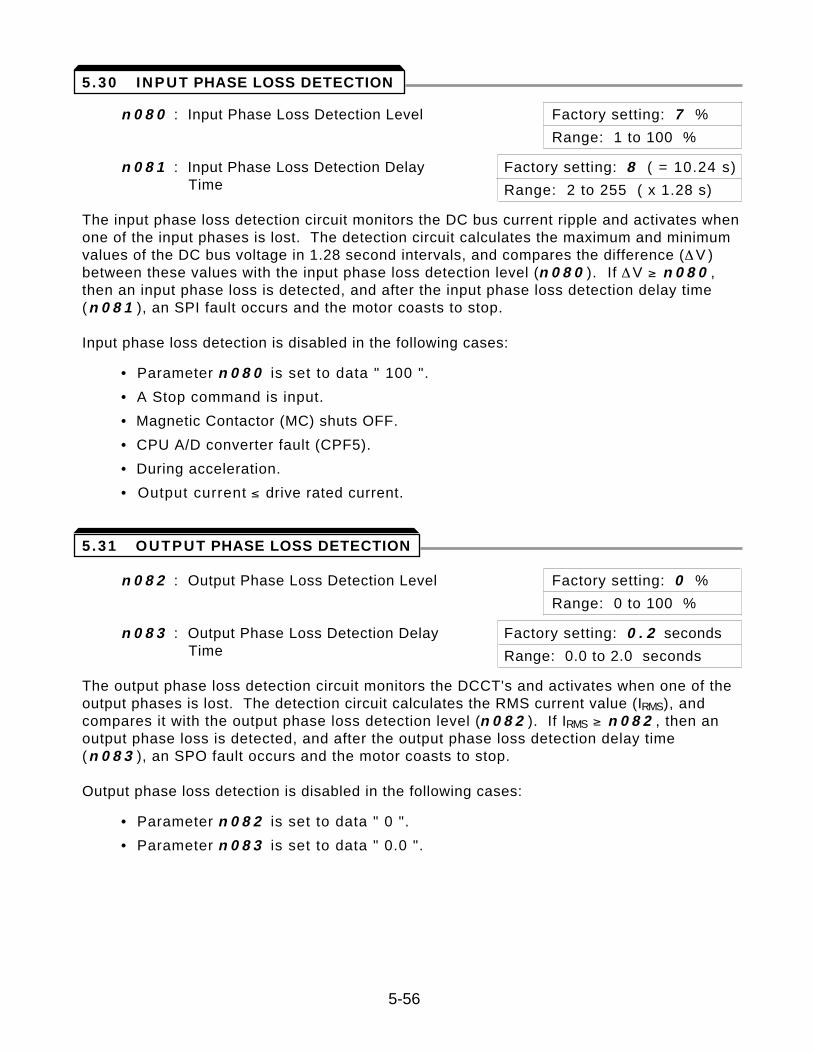
n 0 8 0 : Input Phase Loss Detection Level Factory setting: 7 %
Range: 1 to 100 %
n 0 8 1 : Input Phase Loss Detection Delay Factory setting: 8 ( = 10.24 s)Time Range: 2 to 255 ( x 1.28 s)
The input phase loss detection circuit monitors the DC bus current ripple and activates whenone of the input phases is lost. The detection circuit calculates the maximum and minimumvalues of the DC bus voltage in 1.28 second intervals, and compares the difference (Æ V )between these values with the input phase loss detection level (n 0 8 0 ). If Æ V ³ n 0 8 0 ,then an input phase loss is detected, and after the input phase loss detection delay time (n 0 8 1 ), an SPI fault occurs and the motor coasts to stop.
Input phase loss detection is disabled in the following cases:
• Parameter n 0 8 0 is set to data " 100 ".
• A Stop command is input.
• Magnetic Contactor (MC) shuts OFF.
• CPU A/D converter fault (CPF5).
• During acceleration.
• Output current ² drive rated current.
n 0 8 2 : Output Phase Loss Detection Level Factory setting: 0 %
Range: 0 to 100 %
n 0 8 3 : Output Phase Loss Detection Delay Factory setting: 0 . 2 secondsTime Range: 0.0 to 2.0 seconds
The output phase loss detection circuit monitors the DCCT's and activates when one of theoutput phases is lost. The detection circuit calculates the RMS current value (IRMS), andcompares it with the output phase loss detection level (n 0 8 2 ). If IRMS ³ n 0 8 2 , then anoutput phase loss is detected, and after the output phase loss detection delay time (n 0 8 3 ), an SPO fault occurs and the motor coasts to stop.
Output phase loss detection is disabled in the following cases:
• Parameter n 0 8 2 is set to data " 0 ".
• Parameter n 0 8 3 is set to data " 0.0 ".
5-56
5 .30 INPUT PHASE LOSS DETECTION
5.31 OUTPUT PHASE LOSS DETECTION
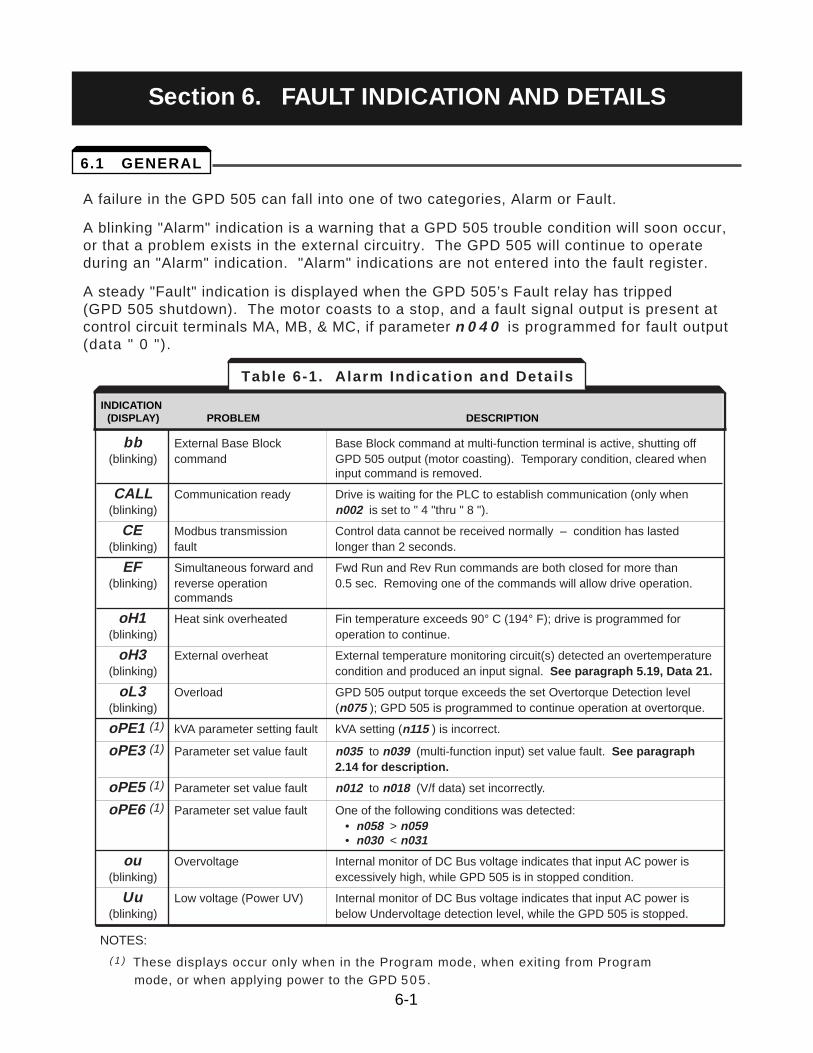
A failure in the GPD 505 can fall into one of two categories, Alarm or Fault.
A blinking "Alarm" indication is a warning that a GPD 505 trouble condition will soon occur,or that a problem exists in the external circuitry. The GPD 505 will continue to operateduring an "Alarm" indication. "Alarm" indications are not entered into the fault register.
A steady "Fault" indication is displayed when the GPD 505’s Fault relay has tripped (GPD 505 shutdown). The motor coasts to a stop, and a fault signal output is present atcontrol circuit terminals MA, MB, & MC, if parameter n 0 4 0 is programmed for fault output(data " 0 ").
INDICATION(DISPLAY) FAILURE INDICATION ITEM DESCRIPTION
bb External Base Block Base Block command at multi-function terminal is active, shutting off (blinking) command GPD 505 output (motor coasting). Temporary condition, cleared when
input command is removed.
CALL Communication ready Drive is waiting for the PLC to establish communication (only when (blinking) n002 is set to " 4 "thru " 8 ").
CE Modbus transmission Control data cannot be received normally – condition has lasted (blinking) fault longer than 2 seconds.
EF Simultaneous forward and Fwd Run and Rev Run commands are both closed for more than (blinking) reverse operation 0.5 sec. Removing one of the commands will allow drive operation.
commands
oH1 Heat sink overheated Fin temperature exceeds 90° C (194° F); drive is programmed for (blinking) operation to continue.
oH3 External overheat External temperature monitoring circuit(s) detected an overtemperature (blinking) condition and produced an input signal. See paragraph 5.19, Data 21.
oL3 Overload GPD 505 output torque exceeds the set Overtorque Detection level (blinking) (n075 ); GPD 505 is programmed to continue operation at overtorque.
oPE1 (1) kVA parameter setting fault kVA setting (n115 ) is incorrect.
oPE3 (1) Parameter set value fault n035 to n039 (multi-function input) set value fault. See paragraph2.14 for description.
oPE5 (1) Parameter set value fault n012 to n018 (V/f data) set incorrectly.
oPE6 (1) Parameter set value fault One of the following conditions was detected:• n058 > n059• n030 < n031
ou Overvoltage Internal monitor of DC Bus voltage indicates that input AC power is (blinking) excessively high, while GPD 505 is in stopped condition.
Uu Low voltage (Power UV) Internal monitor of DC Bus voltage indicates that input AC power is (blinking) below Undervoltage detection level, while the GPD 505 is stopped.
NOTES:
( 1 ) These displays occur only when in the Program mode, when exiting from Programmode, or when applying power to the GPD 505 .
Table 6-1. Alarm Indication and Detai ls
INDICATION(DISPLAY) PROBLEM DESCRIPTION
6-1
6.1 GENERAL
Section 6. FAULT INDICATION AND DETAILS
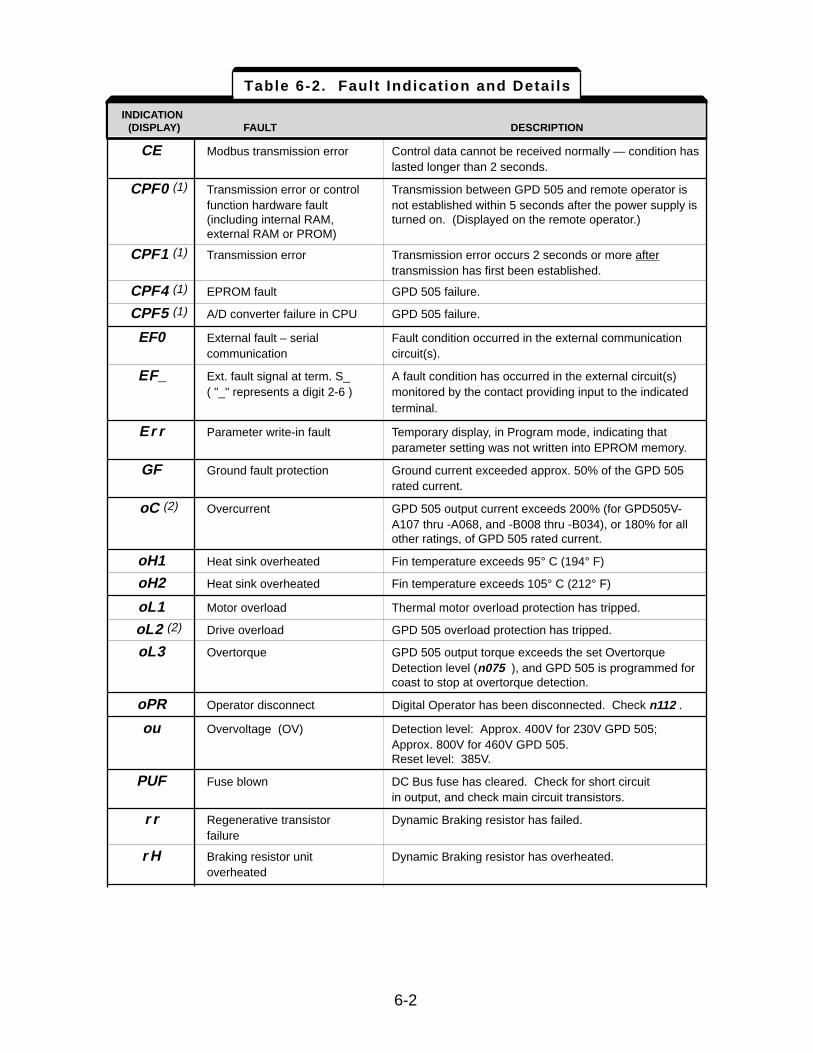
INDICATION(DISPLAY) FAILURE INDICATION ITEM DESCRIPTION
CE Modbus transmission error Control data cannot be received normally — condition haslasted longer than 2 seconds.
CPF0 (1) Transmission error or control Transmission between GPD 505 and remote operator is function hardware fault not established within 5 seconds after the power supply is (including internal RAM, turned on. (Displayed on the remote operator.)external RAM or PROM)
CPF1 (1) Transmission error Transmission error occurs 2 seconds or more aftertransmission has first been established.
CPF4 (1) EPROM fault GPD 505 failure.
CPF5 (1) A/D converter failure in CPU GPD 505 failure.
EF0 External fault – serial Fault condition occurred in the external communicationcommunication circuit(s).
EF_ Ext. fault signal at term. S_ A fault condition has occurred in the external circuit(s) ( "_" represents a digit 2-6 ) monitored by the contact providing input to the indicated
terminal.
Er r Parameter write-in fault Temporary display, in Program mode, indicating that parameter setting was not written into EPROM memory.
GF Ground fault protection Ground current exceeded approx. 50% of the GPD 505 rated current.
oC (2) Overcurrent GPD 505 output current exceeds 200% (for GPD505V-A107 thru -A068, and -B008 thru -B034), or 180% for all other ratings, of GPD 505 rated current.
oH1 Heat sink overheated Fin temperature exceeds 95° C (194° F)
oH2 Heat sink overheated Fin temperature exceeds 105° C (212° F)
oL1 Motor overload Thermal motor overload protection has tripped.
oL2 (2) Drive overload GPD 505 overload protection has tripped.
oL3 Overtorque GPD 505 output torque exceeds the set Overtorque Detection level (n075 ), and GPD 505 is programmed for coast to stop at overtorque detection.
oPR Operator disconnect Digital Operator has been disconnected. Check n112 .
ou Overvoltage (OV) Detection level: Approx. 400V for 230V GPD 505; Approx. 800V for 460V GPD 505. Reset level: 385V.
PUF Fuse blown DC Bus fuse has cleared. Check for short circuit in output, and check main circuit transistors.
r r Regenerative transistor Dynamic Braking resistor has failed.failure
r H Braking resistor unit Dynamic Braking resistor has overheated.overheated
Table 6-2. Fault Indication and Detai ls
INDICATION(DISPLAY) FAULT DESCRIPTION
6-2
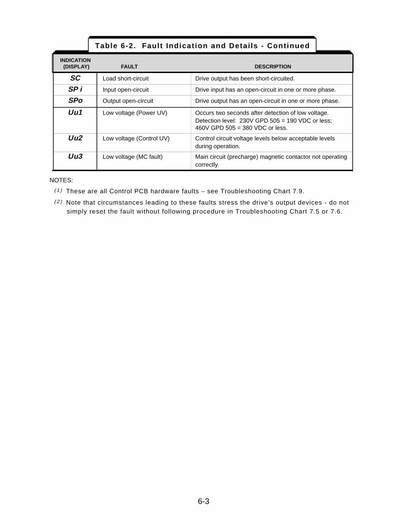
INDICATION(DISPLAY) FAILURE INDICATION ITEM DESCRIPTION
SC Load short-circuit Drive output has been short-circuited.
SP i Input open-circuit Drive input has an open-circuit in one or more phase.
SPo Output open-circuit Drive output has an open-circuit in one or more phase.
Uu1 Low voltage (Power UV) Occurs two seconds after detection of low voltage.Detection level: 230V GPD 505 = 190 VDC or less;460V GPD 505 = 380 VDC or less.
Uu2 Low voltage (Control UV) Control circuit voltage levels below acceptable levels during operation.
Uu3 Low voltage (MC fault) Main circuit (precharge) magnetic contactor not operating correctly.
NOTES:
( 1 ) These are all Control PCB hardware faults – see Troubleshooting Chart 7.9.
( 2 ) Note that circumstances leading to these faults stress the drive’s output devices - do not simply reset the fault without following procedure in Troubleshooting Chart 7.5 or 7.6.
Table 6-2. Fault Indication and Detai ls - Continued
INDICATION(DISPLAY) FAULT DESCRIPTION
6-3
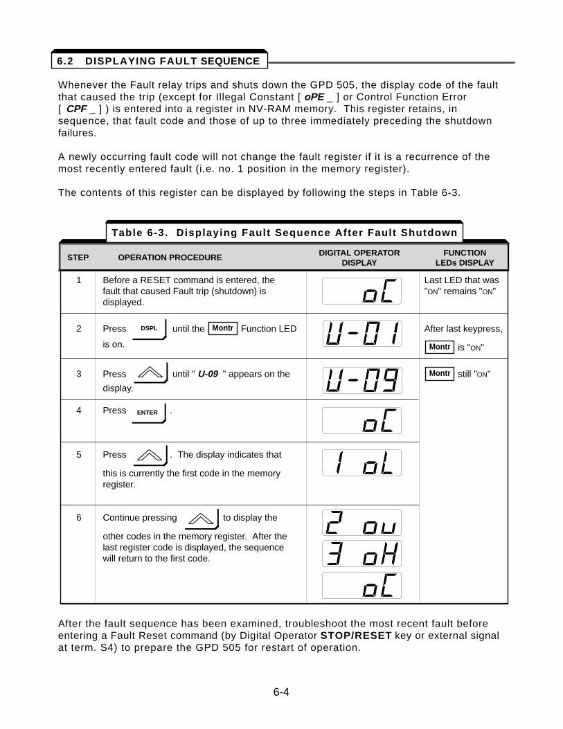
Whenever the Fault relay trips and shuts down the GPD 505, the display code of the faultthat caused the trip (except for Illegal Constant [ oPE _ ] or Control Function Error [ CPF _ ] ) is entered into a register in NV-RAM memory. This register retains, insequence, that fault code and those of up to three immediately preceding the shutdownfailures.
A newly occurring fault code will not change the fault register if it is a recurrence of themost recently entered fault (i.e. no. 1 position in the memory register).
The contents of this register can be displayed by following the steps in Table 6-3.
After the fault sequence has been examined, troubleshoot the most recent fault beforeentering a Fault Reset command (by Digital Operator STOP/RESET key or external signalat term. S4) to prepare the GPD 505 for restart of operation.
STEP OPERATION PROCEDURE DIGITAL DISPLAY
1 Before a RESET command is entered, the Last LED that wasfault that caused Fault trip (shutdown) is "ON" remains "ON"displayed.
2 Press until the Function LED After last keypress,
is on. is "ON"
3 Press until " U-09 " appears on the still "ON"
display.
4 Press .
5 Press . The display indicates that
this is currently the first code in the memory register.
6 Continue pressing to display the
other codes in the memory register. After the last register code is displayed, the sequence will return to the first code.
Montr
Montr
Montr
STEP OPERATION PROCEDURE DIGITAL OPERATOR FUNCTIONDISPLAY LEDs DISPLAY
Table 6-3. Displaying Fault Sequence After Fault Shutdown
6-4
6.2 DISPLAYING FAULT SEQUENCE
DSPL
ENTER
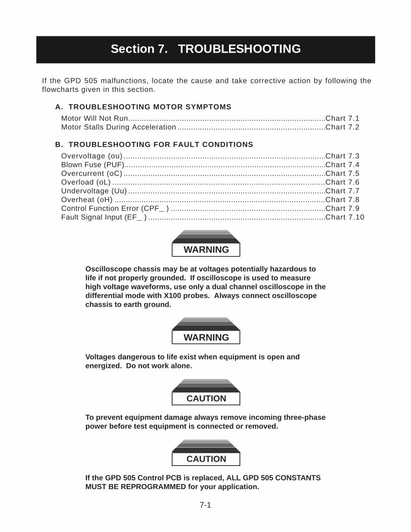
If the GPD 505 malfunctions, locate the cause and take corrective action by following theflowcharts given in this section.
A. TROUBLESHOOTING MOTOR SYMPTOMS
Motor Will Not Run........................................................................................Chart 7.1Motor Stalls During Acceleration ..................................................................Chart 7.2
B. TROUBLESHOOTING FOR FAULT CONDITIONS
Overvoltage (ou) ..........................................................................................Chart 7.3Blown Fuse (PUF)..........................................................................................Chart 7.4Overcurrent (oC) ..........................................................................................Chart 7.5Overload (oL) ...............................................................................................Chart 7.6Undervoltage (Uu) ........................................................................................Chart 7.7Overheat (oH) ..............................................................................................Chart 7.8Control Function Error (CPF ) .....................................................................Chart 7.9Fault Signal Input (EF ) ...............................................................................Chart 7.10
WARNING
Oscilloscope chassis may be at voltages potentially hazardous tolife if not properly grounded. If oscilloscope is used to measurehigh voltage waveforms, use only a dual channel oscilloscope in thedifferential mode with X100 probes. Always connect oscilloscopechassis to earth ground.
WARNING
Voltages dangerous to life exist when equipment is open andenergized. Do not work alone.
CAUTION
To prevent equipment damage always remove incoming three-phasepower before test equipment is connected or removed.
CAUTION
If the GPD 505 Control PCB is replaced, ALL GPD 505 CONSTANTSMUST BE REPROGRAMMED for your application.
7-1
Section 7. TROUBLESHOOTING
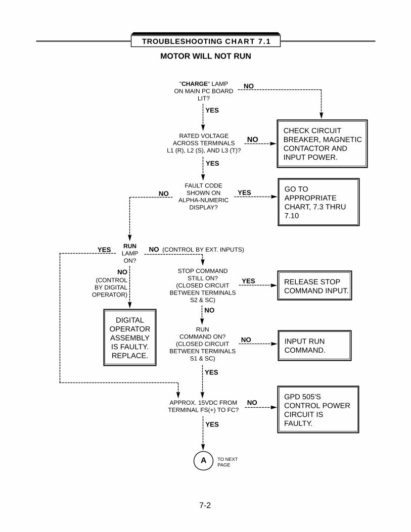
MOTOR WILL NOT RUN
"CHARGE" LAMPON MAIN PC BOARD
LIT?
CHECK CIRCUITBREAKER, MAGNETICCONTACTOR ANDINPUT POWER.
NO
NO
NO
NO
NO (CONTROL BY EXT. INPUTS)
NO(CONTROL BY DIGITAL
OPERATOR)
NO
NO
YES
YES
YES
YES
YES
YES
YES
RATED VOLTAGEACROSS TERMINALS
L1 (R), L2 (S), AND L3 (T)?
FAULT CODESHOWN ON
ALPHA-NUMERICDISPLAY?
GO TO APPROPRIATECHART, 7.3 THRU7.10
RUNLAMPON?
STOP COMMANDSTILL ON?
(CLOSED CIRCUITBETWEEN TERMINALS
S2 & SC)
RUNCOMMAND ON?
(CLOSED CIRCUITBETWEEN TERMINALS
S1 & SC)
RELEASE STOPCOMMAND INPUT.
INPUT RUNCOMMAND.
GPD 505'SCONTROL POWERCIRCUIT ISFAULTY.
APPROX. 15VDC FROMTERMINAL FS(+) TO FC?
A TO NEXTPAGE
DIGITALOPERATORASSEMBLYIS FAULTY.REPLACE.
7-2
TROUBLESHOOTING CHART 7.1
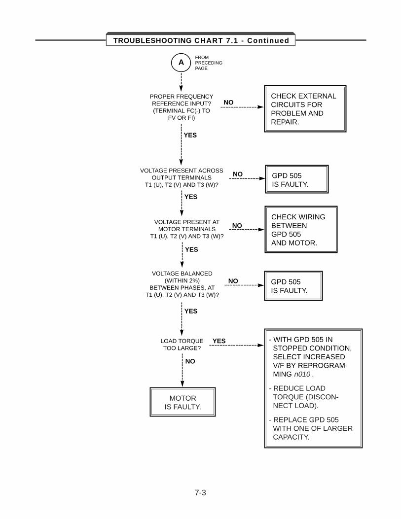
AFROMPRECEDINGPAGE
PROPER FREQUENCYREFERENCE INPUT?(TERMINAL FC(-) TO
FV OR FI)
NO
NO
NO
NO
NO
CHECK EXTERNALCIRCUITS FORPROBLEM ANDREPAIR.
YES
VOLTAGE PRESENT ACROSSOUTPUT TERMINALS
T1 (U), T2 (V) AND T3 (W)?
VOLTAGE PRESENT ATMOTOR TERMINALS
T1 (U), T2 (V) AND T3 (W)?
VOLTAGE BALANCED(WITHIN 2%)
BETWEEN PHASES, ATT1 (U), T2 (V) AND T3 (W)?
GPD 505IS FAULTY.
YES
YES
YES
YES
CHECK WIRINGBETWEENGPD 505AND MOTOR.
GPD 505IS FAULTY.
LOAD TORQUETOO LARGE?
- WITH GPD 505 INSTOPPED CONDITION,SELECT INCREASEDV/F BY REPROGRAM-MING n010 .
- REDUCE LOAD TORQUE (DISCON-NECT LOAD).
- REPLACE GPD 505WITH ONE OF LARGERCAPACITY.
MOTORIS FAULTY.
7-3
TROUBLESHOOTING CHART 7.1 - Continued
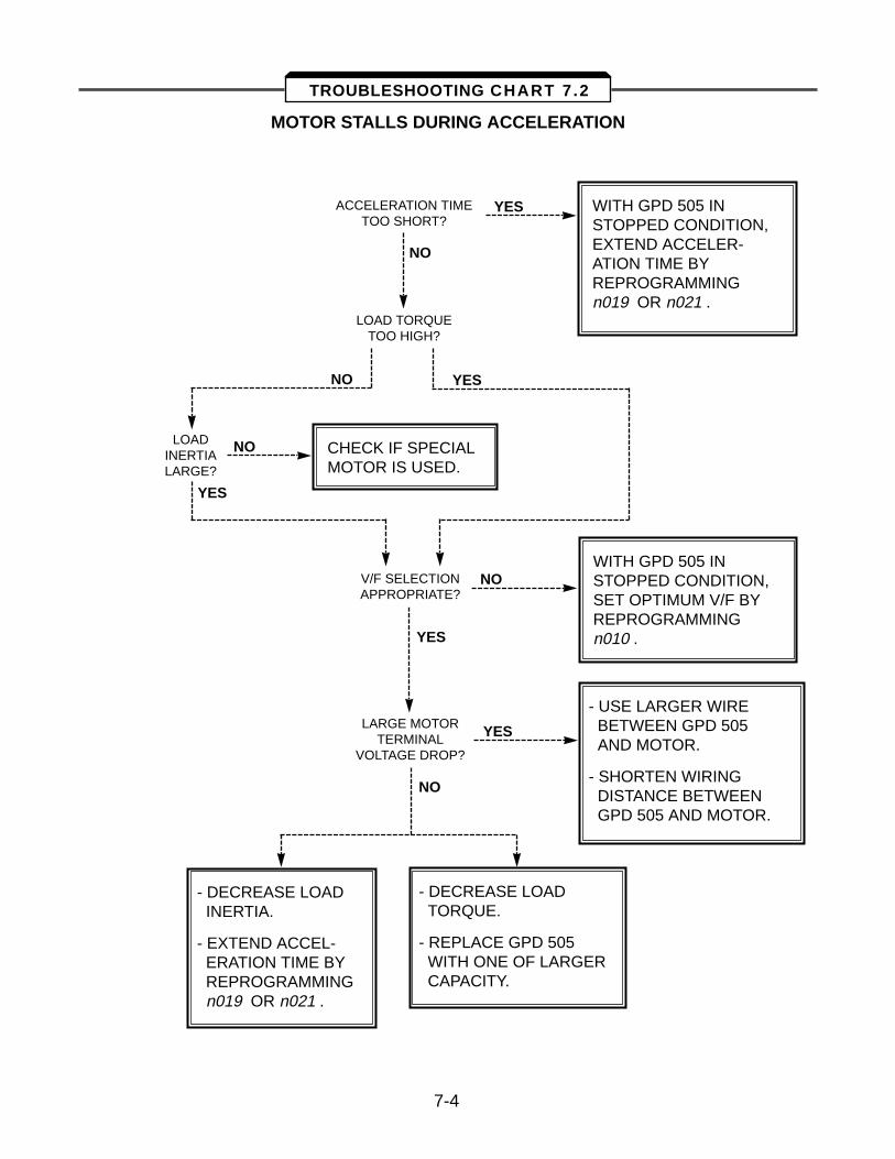
MOTOR STALLS DURING ACCELERATION
ACCELERATION TIMETOO SHORT?
YES
YES
YES
YES
YES
WITH GPD 505 INSTOPPED CONDITION,EXTEND ACCELER-ATION TIME BYREPROGRAMMING n019 OR n021 .
NO
NO
NO
NO
NO
LOAD TORQUETOO HIGH?
LOADINERTIALARGE?
CHECK IF SPECIALMOTOR IS USED.
V/F SELECTIONAPPROPRIATE?
WITH GPD 505 INSTOPPED CONDITION,SET OPTIMUM V/F BYREPROGRAMMING n010 .
LARGE MOTORTERMINAL
VOLTAGE DROP?
- USE LARGER WIREBETWEEN GPD 505AND MOTOR.
- SHORTEN WIRINGDISTANCE BETWEENGPD 505 AND MOTOR.
- DECREASE LOADINERTIA.
- EXTEND ACCEL-ERATION TIME BYREPROGRAMMINGn019 OR n021 .
- DECREASE LOADTORQUE.
- REPLACE GPD 505WITH ONE OF LARGERCAPACITY.
7-4
TROUBLESHOOTING CHART 7.2
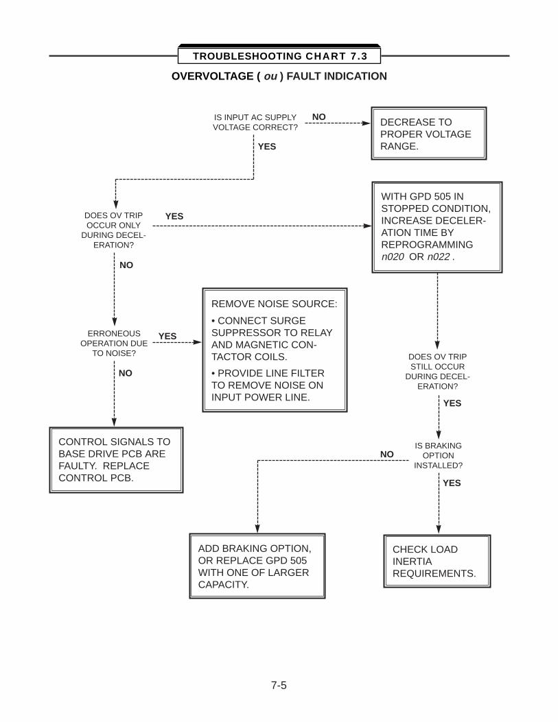
OVERVOLTAGE ( ou ) FAULT INDICATION
IS INPUT AC SUPPLYVOLTAGE CORRECT?
NO
NO
NO
NO
DECREASE TOPROPER VOLTAGERANGE.YES
YES
YES
YES
YES
DOES OV TRIPOCCUR ONLY
DURING DECEL-ERATION?
DOES OV TRIPSTILL OCCUR
DURING DECEL-ERATION?
WITH GPD 505 INSTOPPED CONDITION,INCREASE DECELER-ATION TIME BYREPROGRAMMING n020 OR n022 .
REMOVE NOISE SOURCE:
• CONNECT SURGE SUPPRESSOR TO RELAYAND MAGNETIC CON-TACTOR COILS.
• PROVIDE LINE FILTERTO REMOVE NOISE ONINPUT POWER LINE.
ERRONEOUSOPERATION DUE
TO NOISE?
CONTROL SIGNALS TOBASE DRIVE PCB ARE FAULTY. REPLACE CONTROL PCB.
IS BRAKINGOPTION
INSTALLED?
ADD BRAKING OPTION,OR REPLACE GPD 505WITH ONE OF LARGERCAPACITY.
CHECK LOADINERTIAREQUIREMENTS.
7-5
TROUBLESHOOTING CHART 7.3
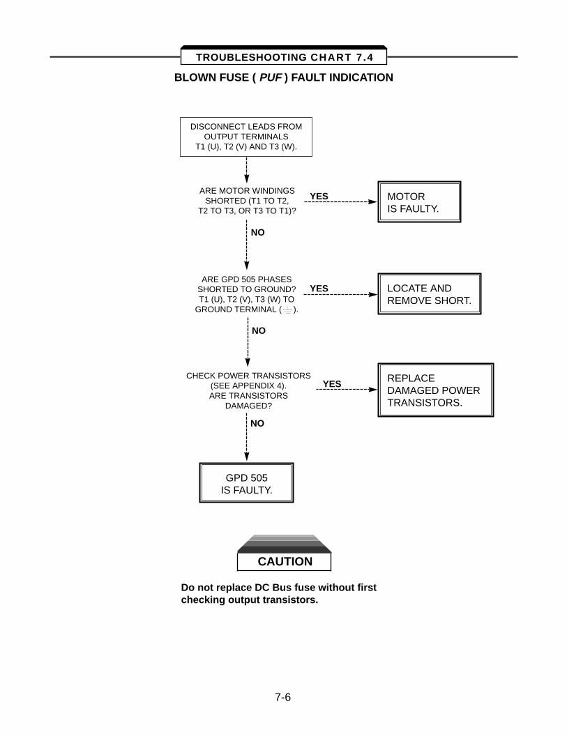
BLOWN FUSE ( PUF ) FAULT INDICATION
CAUTION
Do not replace DC Bus fuse without first checking output transistors.
DISCONNECT LEADS FROMOUTPUT TERMINALS
T1 (U), T2 (V) AND T3 (W).
ARE MOTOR WINDINGSSHORTED (T1 TO T2,
T2 TO T3, OR T3 TO T1)?
MOTORIS FAULTY.
LOCATE ANDREMOVE SHORT.
REPLACEDAMAGED POWERTRANSISTORS.
YES
YES
YES
NO
NO
NO
ARE GPD 505 PHASESSHORTED TO GROUND?T1 (U), T2 (V), T3 (W) TO
GROUND TERMINAL ( ).
CHECK POWER TRANSISTORS(SEE APPENDIX 4).ARE TRANSISTORS
DAMAGED?
GPD 505IS FAULTY.
7-6
TROUBLESHOOTING CHART 7.4
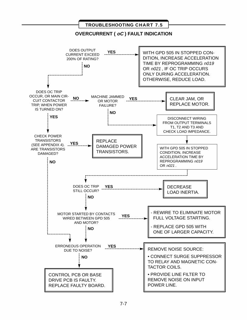
OVERCURRENT ( oC ) FAULT INDICATION
DOES OUTPUTCURRENT EXCEED200% OF RATING?
WITH GPD 505 IN STOPPED CON-DITION, INCREASE ACCELERATION TIME BY REPROGRAMMING n019OR n021 , IF OC TRIP OCCURS ONLY DURING ACCELERATION.OTHERWISE, REDUCE LOAD.
YES
YES
YES
YES
YES
YES
YES
NO
NO
NO
NO
NO
NO
NO
DOES OC TRIP OCCUR, OR MAIN CIR-
CUIT CONTACTOR TRIP, WHEN POWER
IS TURNED ON?
MACHINE JAMMEDOR MOTOR FAILURE?
CLEAR JAM, ORREPLACE MOTOR.
DISCONNECT WIRINGFROM OUTPUT TERMINALS
T1, T2 AND T3 ANDCHECK LOAD IMPEDANCE.
CHECK POWERTRANSISTORS
(SEE APPENDIX 4).ARE TRANSISTORS
DAMAGED?
REPLACEDAMAGED POWERTRANSISTORS.
WITH GPD 505 IN STOPPEDCONDITION, INCREASEACCELERATION TIME BYREPROGRAMMING n019OR n021 .
DOES OC TRIPSTILL OCCUR?
DECREASELOAD INERTIA.
MOTOR STARTED BY CONTACTSWIRED BETWEEN GPD 505
AND MOTOR?
- REWIRE TO ELIMINATE MOTORFULL VOLTAGE STARTING.
- REPLACE GPD 505 WITHONE OF LARGER CAPACITY.
ERRONEOUS OPERATIONDUE TO NOISE? REMOVE NOISE SOURCE:
• CONNECT SURGE SUPPRESSORTO RELAY AND MAGNETIC CON-TACTOR COILS.
• PROVIDE LINE FILTER TO REMOVE NOISE ON INPUT POWER LINE.
CONTROL PCB OR BASE DRIVE PCB IS FAULTY. REPLACE FAULTY BOARD.
7-7
TROUBLESHOOTING CHART 7.5
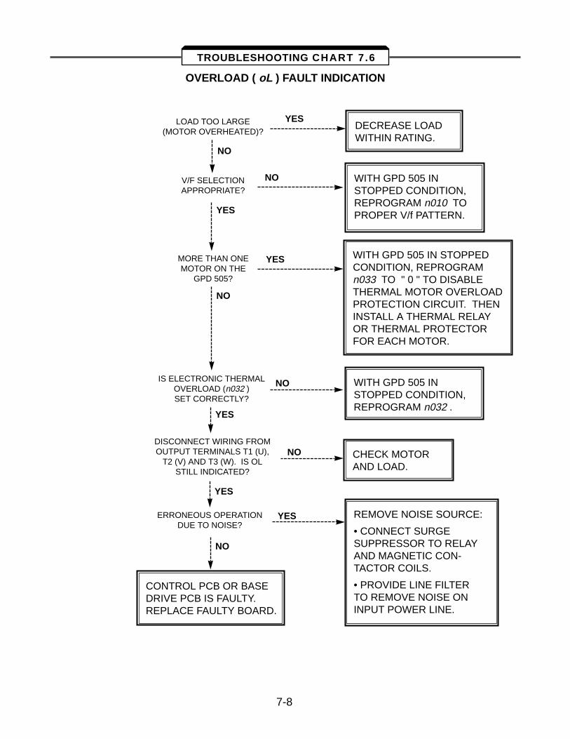
OVERLOAD ( oL ) FAULT INDICATION
LOAD TOO LARGE(MOTOR OVERHEATED)?
YES
YES
YES
YES
YES
DECREASE LOADWITHIN RATING.
CHECK MOTORAND LOAD.
NO
NO
NO
NO
NO
V/F SELECTIONAPPROPRIATE?
WITH GPD 505 INSTOPPED CONDITION,REPROGRAM n010 TOPROPER V/f PATTERN.
YES
NO
MORE THAN ONEMOTOR ON THE
GPD 505?
WITH GPD 505 IN STOPPED CONDITION, REPROGRAM n033 TO " 0 " TO DISABLE THERMAL MOTOR OVERLOAD PROTECTION CIRCUIT. THEN INSTALL A THERMAL RELAY OR THERMAL PROTECTOR FOR EACH MOTOR.
WITH GPD 505 INSTOPPED CONDITION,REPROGRAM n032 .
IS ELECTRONIC THERMALOVERLOAD (n032 )SET CORRECTLY?
DISCONNECT WIRING FROMOUTPUT TERMINALS T1 (U),
T2 (V) AND T3 (W). IS OL STILL INDICATED?
REMOVE NOISE SOURCE:
• CONNECT SURGE SUPPRESSOR TO RELAYAND MAGNETIC CON-TACTOR COILS.
• PROVIDE LINE FILTERTO REMOVE NOISE ONINPUT POWER LINE.
CONTROL PCB OR BASE DRIVE PCB IS FAULTY. REPLACE FAULTY BOARD.
ERRONEOUS OPERATIONDUE TO NOISE?
7-8
TROUBLESHOOTING CHART 7.6
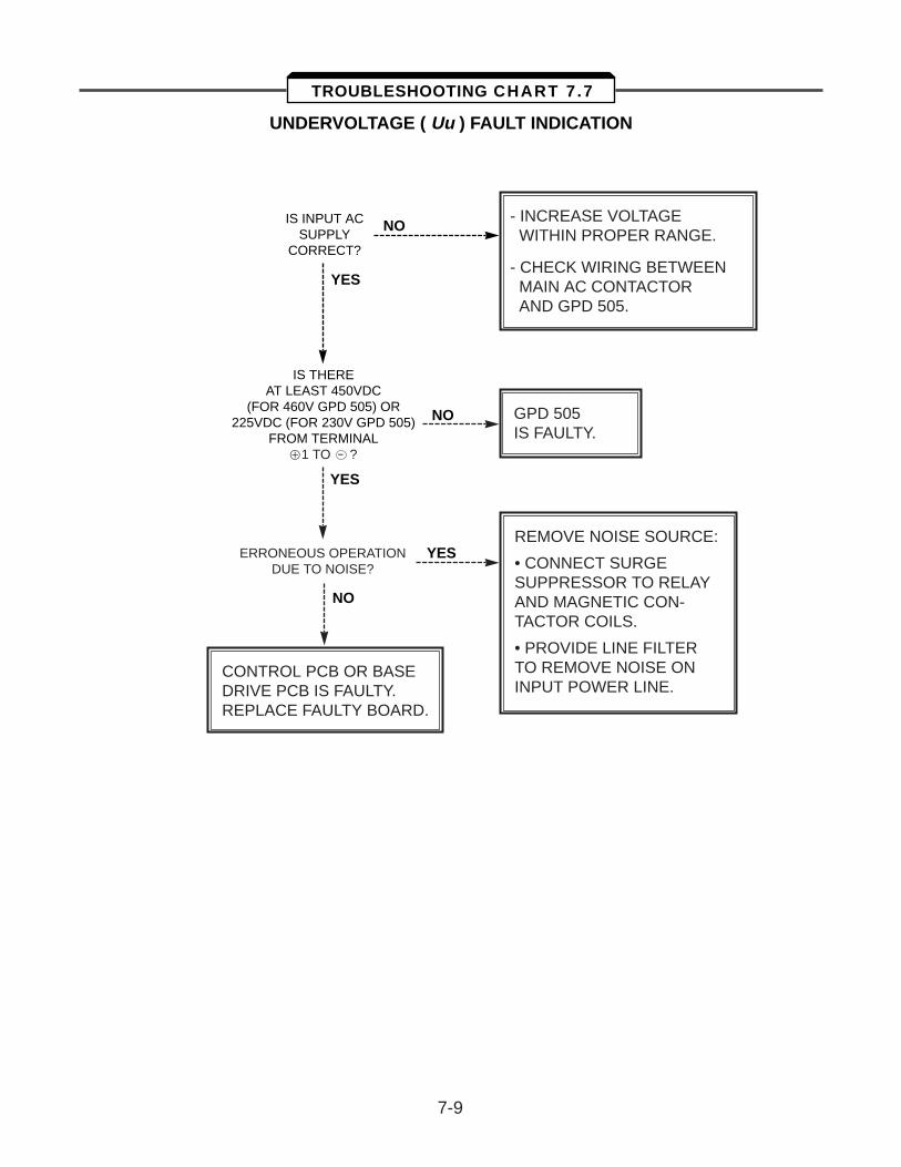
UNDERVOLTAGE ( Uu ) FAULT INDICATION
IS INPUT ACSUPPLY
CORRECT?
NO
NO
YES
YES
NO
YES
IS THEREAT LEAST 450VDC
(FOR 460V GPD 505) OR225VDC (FOR 230V GPD 505)
FROM TERMINAL Å1 TO - ?
- INCREASE VOLTAGEWITHIN PROPER RANGE.
- CHECK WIRING BETWEENMAIN AC CONTACTORAND GPD 505.
GPD 505IS FAULTY.
REMOVE NOISE SOURCE:
• CONNECT SURGE SUPPRESSOR TO RELAYAND MAGNETIC CON-TACTOR COILS.
• PROVIDE LINE FILTERTO REMOVE NOISE ONINPUT POWER LINE.
ERRONEOUS OPERATIONDUE TO NOISE?
CONTROL PCB OR BASE DRIVE PCB IS FAULTY. REPLACE FAULTY BOARD.
7-9
TROUBLESHOOTING CHART 7.7
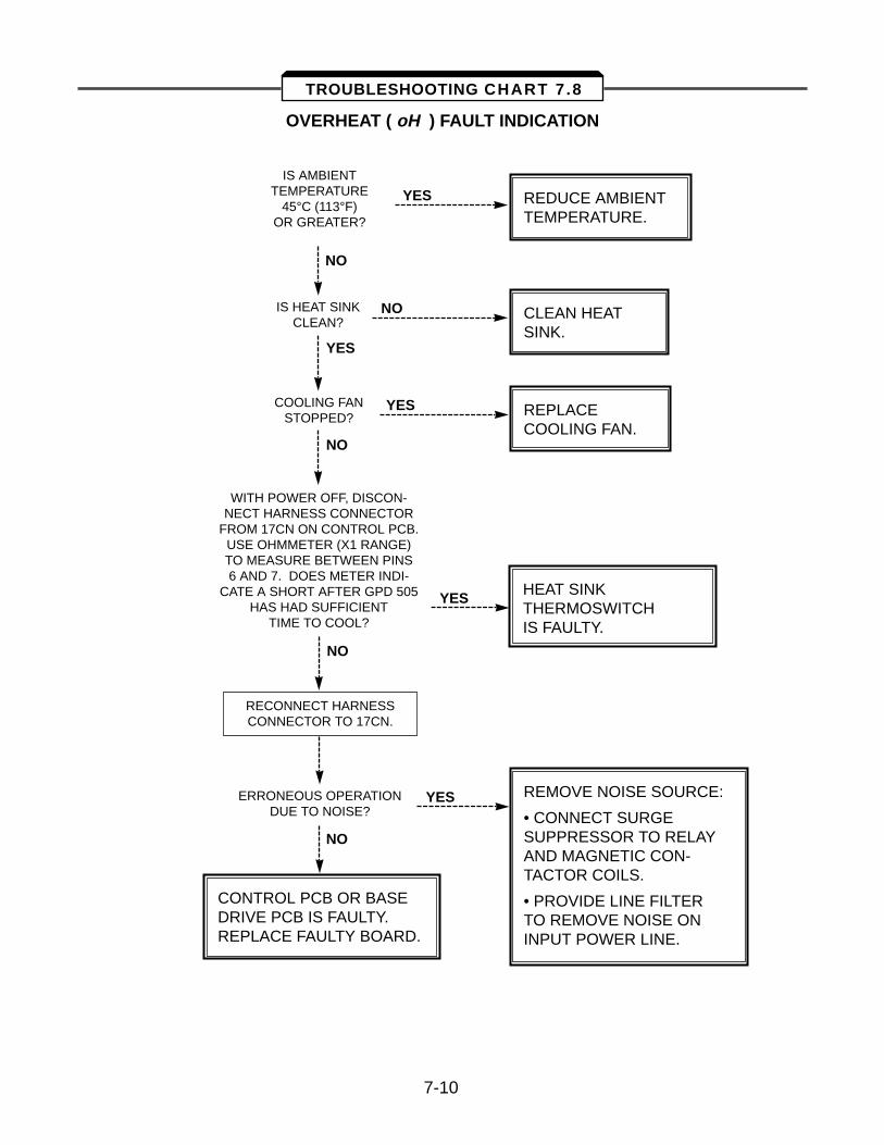
OVERHEAT ( oH ) FAULT INDICATION
IS AMBIENTTEMPERATURE
45°C (113°F)OR GREATER?
REDUCE AMBIENTTEMPERATURE.
HEAT SINKTHERMOSWITCHIS FAULTY.
YES
YES
YES
YES
YES
NO
NO
NO
NO
NO
IS HEAT SINKCLEAN?
COOLING FANSTOPPED?
CLEAN HEATSINK.
REPLACECOOLING FAN.
WITH POWER OFF, DISCON-NECT HARNESS CONNECTOR
FROM 17CN ON CONTROL PCB.USE OHMMETER (X1 RANGE)TO MEASURE BETWEEN PINS6 AND 7. DOES METER INDI-
CATE A SHORT AFTER GPD 505HAS HAD SUFFICIENT
TIME TO COOL?
RECONNECT HARNESSCONNECTOR TO 17CN.
ERRONEOUS OPERATIONDUE TO NOISE?
CONTROL PCB OR BASE DRIVE PCB IS FAULTY. REPLACE FAULTY BOARD.
REMOVE NOISE SOURCE:
• CONNECT SURGE SUPPRESSOR TO RELAYAND MAGNETIC CON-TACTOR COILS.
• PROVIDE LINE FILTERTO REMOVE NOISE ONINPUT POWER LINE.
7-10
TROUBLESHOOTING CHART 7.8
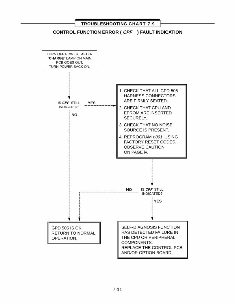
CONTROL FUNCTION ERROR ( CPF ) FAULT INDICATION
1. CHECK THAT ALL GPD 505HARNESS CONNECTORSARE FIRMLY SEATED.
2. CHECK THAT CPU ANDEPROM ARE INSERTEDSECURELY.
3. CHECK THAT NO NOISE SOURCE IS PRESENT.
4. REPROGRAM n001 USINGFACTORY RESET CODES.OBSERVE CAUTIONON PAGE iv.
TURN OFF POWER. AFTER"CHARGE" LAMP ON MAIN
PCB GOES OUT,TURN POWER BACK ON.
IS CPF STILLINDICATED?
IS CPF STILLINDICATED?
YES
YES
NO
NO
SELF-DIAGNOSIS FUNCTIONHAS DETECTED FAILURE INTHE CPU OR PERIPHERALCOMPONENTS.REPLACE THE CONTROL PCB AND/OR OPTION BOARD.
GPD 505 IS OK.RETURN TO NORMALOPERATION.
7-11
TROUBLESHOOTING CHART 7.9
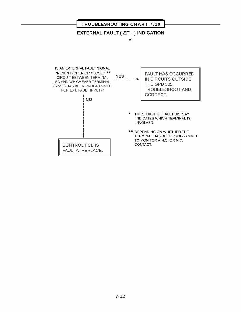
EXTERNAL FAULT ( EF ) INDICATION
IS AN EXTERNAL FAULT SIGNALPRESENT (OPEN OR CLOSED
CIRCUIT BETWEEN TERMINAL SC AND WHICHEVER TERMINAL
(S2-S6) HAS BEEN PROGRAMMEDFOR EXT. FAULT INPUT)?
YES FAULT HAS OCCURREDIN CIRCUITS OUTSIDETHE GPD 505.TROUBLESHOOT ANDCORRECT.
NO
CONTROL PCB ISFAULTY. REPLACE.
7-12
THIRD DIGIT OF FAULT DISPLAY INDICATES WHICH TERMINAL IS INVOLVED.
DEPENDING ON WHETHER THE TERMINAL HAS BEEN PROGRAMMED TO MONITOR A N.O. OR N.C. CONTACT.
TROUBLESHOOTING CHART 7 .10
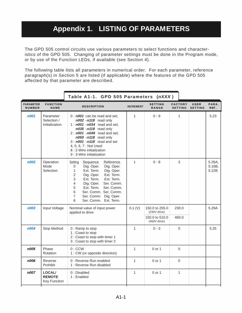
The GPD 505 control circuits use various parameters to select functions and character-istics of the GPD 505. Changing of parameter settings must be done in the Program mode,or by use of the Function LEDs, if available (see Section 4).
The following table lists all parameters in numerical order. For each parameter, referenceparagraph(s) in Section 5 are listed (if applicable) where the features of the GPD 505affected by that parameter are described.
n001 Parameter 0 : n001 can be read and set; 1 0 - 9 1 5.23Selection / n002 -n118 read onlyInitialization 1 : n001 -n034 read and set;
n035 -n118 read only2 : n001 -n049 read and set;
n050 -n118 read only3 : n001 -n118 read and set4, 5, 6, 7 : Not Used8 : 2-Wire initialization9 : 3-Wire initialization
n002 Operation Setting Sequence Reference 1 0 - 8 3 5.26A,Mode 0 Dig. Oper. Dig. Oper. 5.16B,Selection 1 Ext. Term. Dig. Oper. 5.22B
2 Dig. Oper. Ext. Term.3 Ext. Term. Ext. Term.4 Dig. Oper. Ser. Comm.5 Ext. Term. Ser. Comm.6 Ser. Comm. Ser. Comm.7 Ser. Comm. Dig. Oper.8 Ser. Comm. Ext. Term.
n003 Input Voltage Nominal value of input power 0.1 (V) 150.0 to 255.0 230.0 5.29Aapplied to drive (230V drive)
150.0 to 510.0 460.0(460V drive)
n004 Stop Method 0 : Ramp to stop 1 0 - 3 0 5.251 : Coast to stop2 : Coast to stop with timer 13 : Coast to stop with timer 2
n005 Phase 0 : CCW 1 0 or 1 0Rotation 1 : CW (or opposite direction)
n006 Reverse 0 : Reverse Run enabled 1 0 or 1 0Prohibit 1 : Reverse Run disabled
n007 LOCAL/ 0 : Disabled 1 0 or 1 1REMOTE 1 : EnabledKey Function
Table A1-1 . GPD 505 Parameters (nXXX )
PARAMETER FUNCTION S E T T I N G F A C T O R Y U S E R P A R A .N U M B E R N A M E DESCRIPTION INCREMENT R A N G E SETT ING SETT ING REF .
A1-1
Appendix 1. LISTING OF PARAMETERS
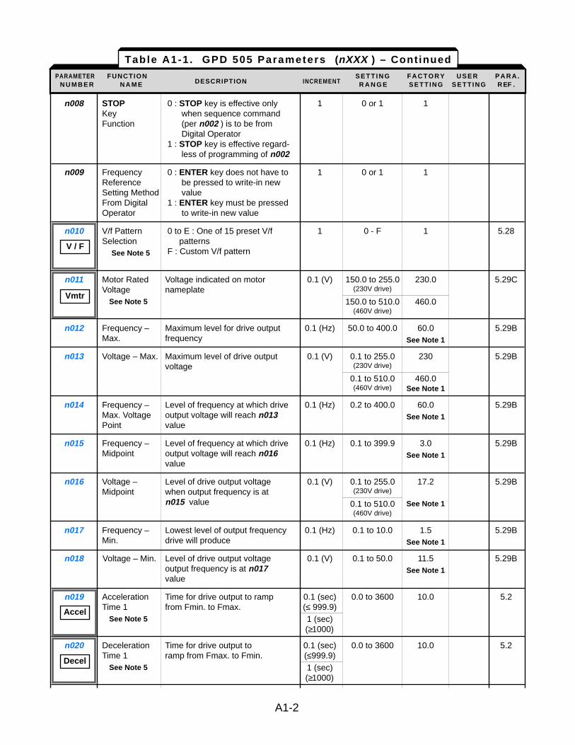
n008 STOP 0 : STOP key is effective only 1 0 or 1 1Key when sequence command Function (per n002 ) is to be from
Digital Operator 1 : STOP key is effective regard-
less of programming of n002
n009 Frequency 0 : ENTER key does not have to 1 0 or 1 1Reference be pressed to write-in new Setting Method valueFrom Digital 1 : ENTER key must be pressed Operator to write-in new value
n010 V/f Pattern 0 to E : One of 15 preset V/f 1 0 - F 1 5.28Selection patterns
See Note 5 F : Custom V/f pattern
n011 Motor Rated Voltage indicated on motor 0.1 (V) 150.0 to 255.0 230.0 5.29CVoltage nameplate (230V drive)
See Note 5 150.0 to 510.0 460.0(460V drive)
n012 Frequency – Maximum level for drive output 0.1 (Hz) 50.0 to 400.0 60.0 5.29BMax. frequency See Note 1
n013 Voltage – Max. Maximum level of drive output 0.1 (V) 0.1 to 255.0 230 5.29Bvoltage (230V drive)
0.1 to 510.0 460.0(460V drive) See Note 1
n014 Frequency – Level of frequency at which drive 0.1 (Hz) 0.2 to 400.0 60.0 5.29BMax. Voltage output voltage will reach n013 See Note 1Point value
n015 Frequency – Level of frequency at which drive 0.1 (Hz) 0.1 to 399.9 3.0 5.29BMidpoint output voltage will reach n016 See Note 1
value
n016 Voltage – Level of drive output voltage 0.1 (V) 0.1 to 255.0 17.2 5.29BMidpoint when output frequency is at (230V drive)
n015 value 0.1 to 510.0 See Note 1(460V drive)
n017 Frequency – Lowest level of output frequency 0.1 (Hz) 0.1 to 10.0 1.5 5.29BMin. drive will produce See Note 1
n018 Voltage – Min. Level of drive output voltage 0.1 (V) 0.1 to 50.0 11.5 5.29Boutput frequency is at n017 See Note 1value
n019 Acceleration Time for drive output to ramp 0.1 (sec) 0.0 to 3600 10.0 5.2Time 1 from Fmin. to Fmax. (≤ 999.9)
See Note 5 1 (sec)(≥1000)
n020 Deceleration Time for drive output to 0.1 (sec) 0.0 to 3600 10.0 5.2Time 1 ramp from Fmax. to Fmin. (≤999.9)
See Note 5 1 (sec)(≥1000)
Table A1-1 . GPD 505 Parameters (nXXX ) – ContinuedPARAMETER FUNCTION S E T T I N G F A C T O R Y U S E R P A R A .
N U M B E R N A M E DESCRIPTION INCREMENT R A N G E SETT ING SETT ING REF .
A1-2
V / F
Vmtr
Accel
Decel
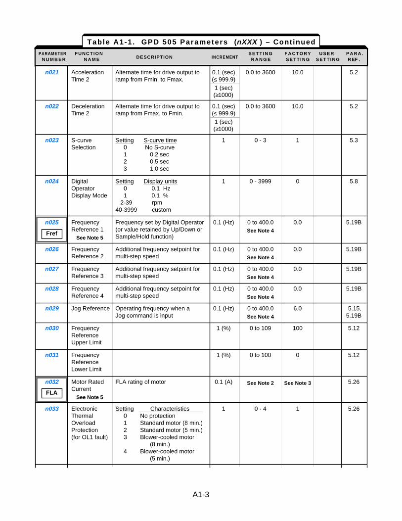
n021 Acceleration Alternate time for drive output to 0.1 (sec) 0.0 to 3600 10.0 5.2Time 2 ramp from Fmin. to Fmax. (≤ 999.9)
1 (sec)(≥1000)
n022 Deceleration Alternate time for drive output to 0.1 (sec) 0.0 to 3600 10.0 5.2Time 2 ramp from Fmax. to Fmin. (≤ 999.9)
1 (sec)(≥1000)
n023 S-curve Setting S-curve time 1 0 - 3 1 5.3Selection 0 No S-curve
1 0.2 sec2 0.5 sec3 1.0 sec
n024 Digital Setting Display units 1 0 - 3999 0 5.8Operator 0 0.1 HzDisplay Mode 1 0.1 %
2-39 rpm 40-3999 custom
n025 Frequency Frequency set by Digital Operator 0.1 (Hz) 0 to 400.0 0.0 5.19BReference 1 (or value retained by Up/Down or See Note 4
See Note 5 Sample/Hold function)
n026 Frequency Additional frequency setpoint for 0.1 (Hz) 0 to 400.0 0.0 5.19BReference 2 multi-step speed See Note 4
n027 Frequency Additional frequency setpoint for 0.1 (Hz) 0 to 400.0 0.0 5.19BReference 3 multi-step speed See Note 4
n028 Frequency Additional frequency setpoint for 0.1 (Hz) 0 to 400.0 0.0 5.19BReference 4 multi-step speed See Note 4
n029 Jog Reference Operating frequency when a 0.1 (Hz) 0 to 400.0 6.0 5.15,Jog command is input See Note 4 5.19B
n030 Frequency 1 (%) 0 to 109 100 5.12Reference Upper Limit
n031 Frequency 1 (%) 0 to 100 0 5.12Reference Lower Limit
n032 Motor Rated FLA rating of motor 0.1 (A) See Note 2 See Note 3 5.26Current
See Note 5
n033 Electronic Setting Characteristics 1 0 - 4 1 5.26Thermal 0 No protectionOverload 1 Standard motor (8 min.)Protection 2 Standard motor (5 min.)(for OL1 fault) 3 Blower-cooled motor
(8 min.)4 Blower-cooled motor
(5 min.)
Table A1-1 . GPD 505 Parameters (nXXX ) – ContinuedPARAMETER FUNCTION S E T T I N G F A C T O R Y U S E R P A R A .
N U M B E R N A M E DESCRIPTION INCREMENT R A N G E SETT ING SETT ING REF .
A1-3
Fref
FLA
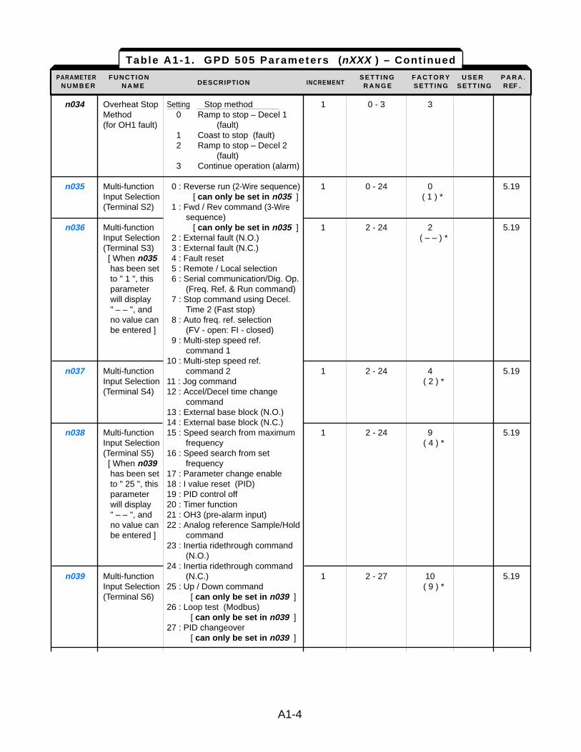
n034 Overheat Stop Setting Stop method 1 0 - 3 3Method 0 Ramp to stop – Decel 1(for OH1 fault) (fault)
1 Coast to stop (fault)2 Ramp to stop – Decel 2
(fault)3 Continue operation (alarm)
n035 Multi-function 0 : Reverse run (2-Wire sequence) 1 0 - 24 0 5.19Input Selection [ can only be set in n035 ] ( 1 ) *(Terminal S2) 1 : Fwd / Rev command (3-Wire
sequence)n036 Multi-function [ can only be set in n035 ] 1 2 - 24 2 5.19
Input Selection 2 : External fault (N.O.) ( – – ) *(Terminal S3) 3 : External fault (N.C.)[ When n035 4 : Fault resethas been set 5 : Remote / Local selectionto " 1 ", this 6 : Serial communication/Dig. Op. parameter (Freq. Ref. & Run command)will display 7 : Stop command using Decel." – – ", and Time 2 (Fast stop)no value can 8 : Auto freq. ref. selectionbe entered ] (FV - open: FI - closed)
9 : Multi-step speed ref. command 1
10 : Multi-step speed ref. n037 Multi-function command 2 1 2 - 24 4 5.19
Input Selection 11 : Jog command ( 2 ) *(Terminal S4) 12 : Accel/Decel time change
command13 : External base block (N.O.)14 : External base block (N.C.)
n038 Multi-function 15 : Speed search from maximum 1 2 - 24 9 5.19Input Selection frequency ( 4 ) *(Terminal S5) 16 : Speed search from set [ When n039 frequencyhas been set 17 : Parameter change enableto " 25 ", this 18 : I value reset (PID)parameter 19 : PID control offwill display 20 : Timer function " – – ", and 21 : OH3 (pre-alarm input)no value can 22 : Analog reference Sample/Holdbe entered ] command
23 : Inertia ridethrough command (N.O.)
24 : Inertia ridethrough command n039 Multi-function (N.C.) 1 2 - 27 10 5.19
Input Selection 25 : Up / Down command ( 9 ) *(Terminal S6) [ can only be set in n039 ]
26 : Loop test (Modbus) [ can only be set in n039 ]
27 : PID changeover[ can only be set in n039 ]
Table A1-1 . GPD 505 Parameters (nXXX ) – Continued
PARAMETER FUNCTION S E T T I N G F A C T O R Y U S E R P A R A .N U M B E R N A M E DESCRIPTION INCREMENT R A N G E SETT ING SETT ING REF .
A1-4
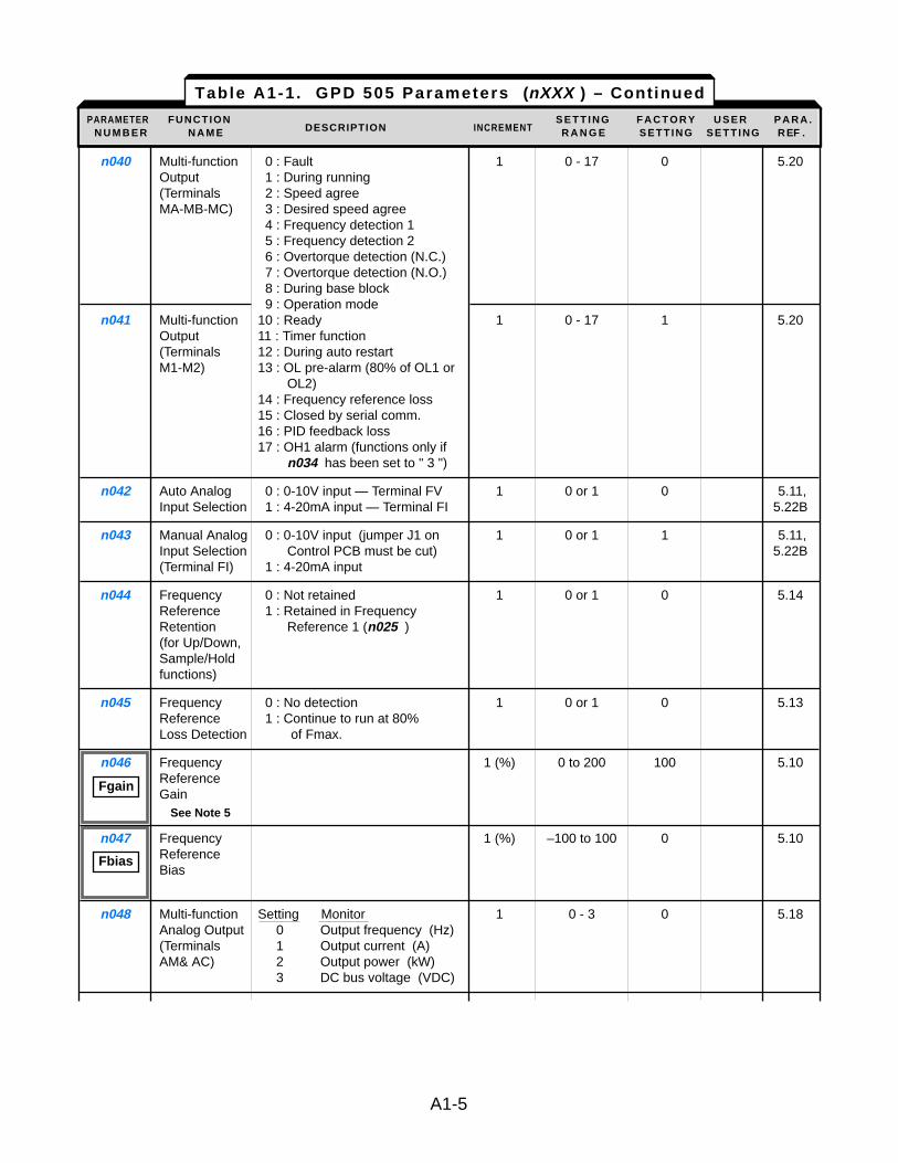
n040 Multi-function 0 : Fault 1 0 - 17 0 5.20Output 1 : During running(Terminals 2 : Speed agreeMA-MB-MC) 3 : Desired speed agree
4 : Frequency detection 15 : Frequency detection 26 : Overtorque detection (N.C.)7 : Overtorque detection (N.O.)8 : During base block9 : Operation mode
n041 Multi-function 10 : Ready 1 0 - 17 1 5.20Output 11 : Timer function(Terminals 12 : During auto restartM1-M2) 13 : OL pre-alarm (80% of OL1 or
OL2)14 : Frequency reference loss15 : Closed by serial comm.16 : PID feedback loss17 : OH1 alarm (functions only if
n034 has been set to " 3 ")
n042 Auto Analog 0 : 0-10V input — Terminal FV 1 0 or 1 0 5.11,Input Selection 1 : 4-20mA input — Terminal FI 5.22B
n043 Manual Analog 0 : 0-10V input (jumper J1 on 1 0 or 1 1 5.11,Input Selection Control PCB must be cut) 5.22B(Terminal FI) 1 : 4-20mA input
n044 Frequency 0 : Not retained 1 0 or 1 0 5.14Reference 1 : Retained in Frequency Retention Reference 1 (n025 )(for Up/Down,Sample/Hold functions)
n045 Frequency 0 : No detection 1 0 or 1 0 5.13Reference 1 : Continue to run at 80% Loss Detection of Fmax.
n046 Frequency 1 (%) 0 to 200 100 5.10Reference Gain
See Note 5
n047 Frequency 1 (%) –100 to 100 0 5.10Reference Bias
n048 Multi-function Setting Monitor 1 0 - 3 0 5.18Analog Output 0 Output frequency (Hz)(Terminals 1 Output current (A)AM& AC) 2 Output power (kW)
3 DC bus voltage (VDC)
Table A1-1 . GPD 505 Parameters (nXXX ) – Continued
PARAMETER FUNCTION S E T T I N G F A C T O R Y U S E R P A R A .N U M B E R N A M E DESCRIPTION INCREMENT R A N G E SETT ING SETT ING REF .
A1-5
Fgain
Fbias
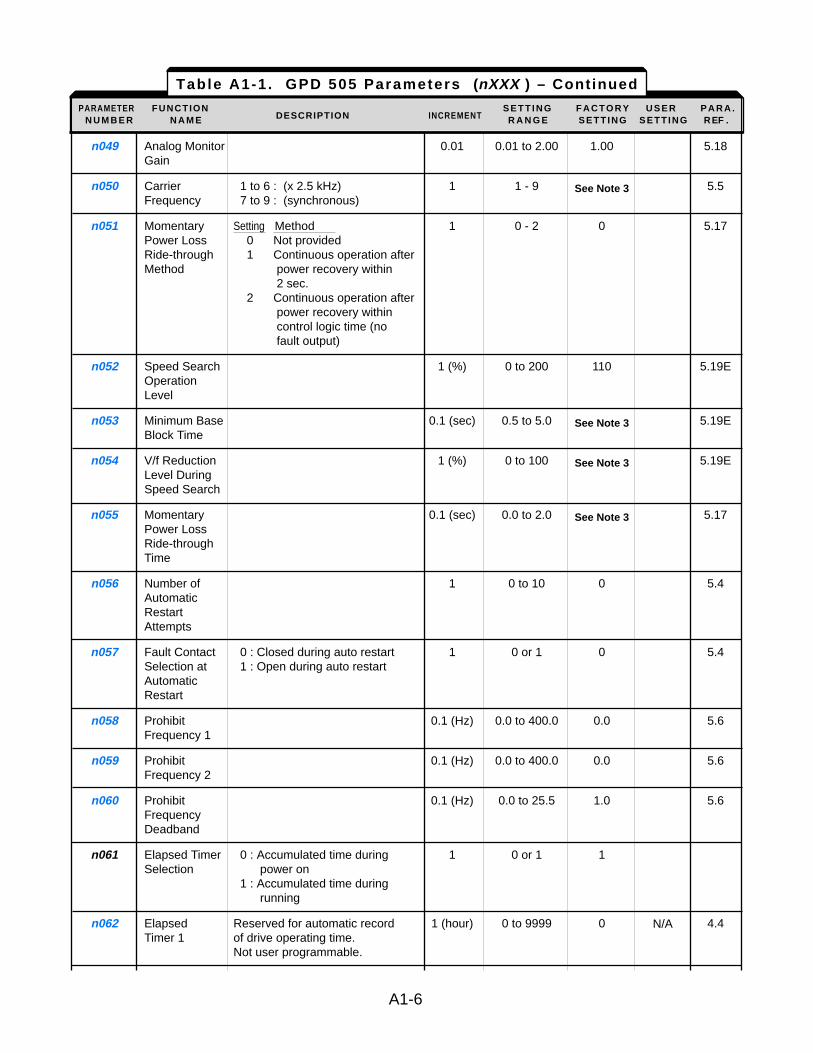
n049 Analog Monitor 0.01 0.01 to 2.00 1.00 5.18Gain
n050 Carrier 1 to 6 : (x 2.5 kHz) 1 1 - 9 See Note 3 5.5Frequency 7 to 9 : (synchronous)
n051 Momentary Setting Method 1 0 - 2 0 5.17Power Loss 0 Not providedRide-through 1 Continuous operation after Method power recovery within
2 sec.2 Continuous operation after
power recovery within control logic time (no fault output)
n052 Speed Search 1 (%) 0 to 200 110 5.19EOperation Level
n053 Minimum Base 0.1 (sec) 0.5 to 5.0 See Note 3 5.19EBlock Time
n054 V/f Reduction 1 (%) 0 to 100 See Note 3 5.19ELevel During Speed Search
n055 Momentary 0.1 (sec) 0.0 to 2.0 See Note 3 5.17Power Loss Ride-through Time
n056 Number of 1 0 to 10 0 5.4AutomaticRestart Attempts
n057 Fault Contact 0 : Closed during auto restart 1 0 or 1 0 5.4Selection at 1 : Open during auto restartAutomatic Restart
n058 Prohibit 0.1 (Hz) 0.0 to 400.0 0.0 5.6Frequency 1
n059 Prohibit 0.1 (Hz) 0.0 to 400.0 0.0 5.6Frequency 2
n060 Prohibit 0.1 (Hz) 0.0 to 25.5 1.0 5.6Frequency Deadband
n061 Elapsed Timer 0 : Accumulated time during 1 0 or 1 1Selection power on
1 : Accumulated time during running
n062 Elapsed Reserved for automatic record 1 (hour) 0 to 9999 0 4.4Timer 1 of drive operating time.
Not user programmable.
Table A1-1 . GPD 505 Parameters (nXXX ) – Continued
PARAMETER FUNCTION S E T T I N G F A C T O R Y U S E R P A R A .N U M B E R N A M E DESCRIPTION INCREMENT R A N G E SETT ING SETT ING REF .
A1-6
N/A
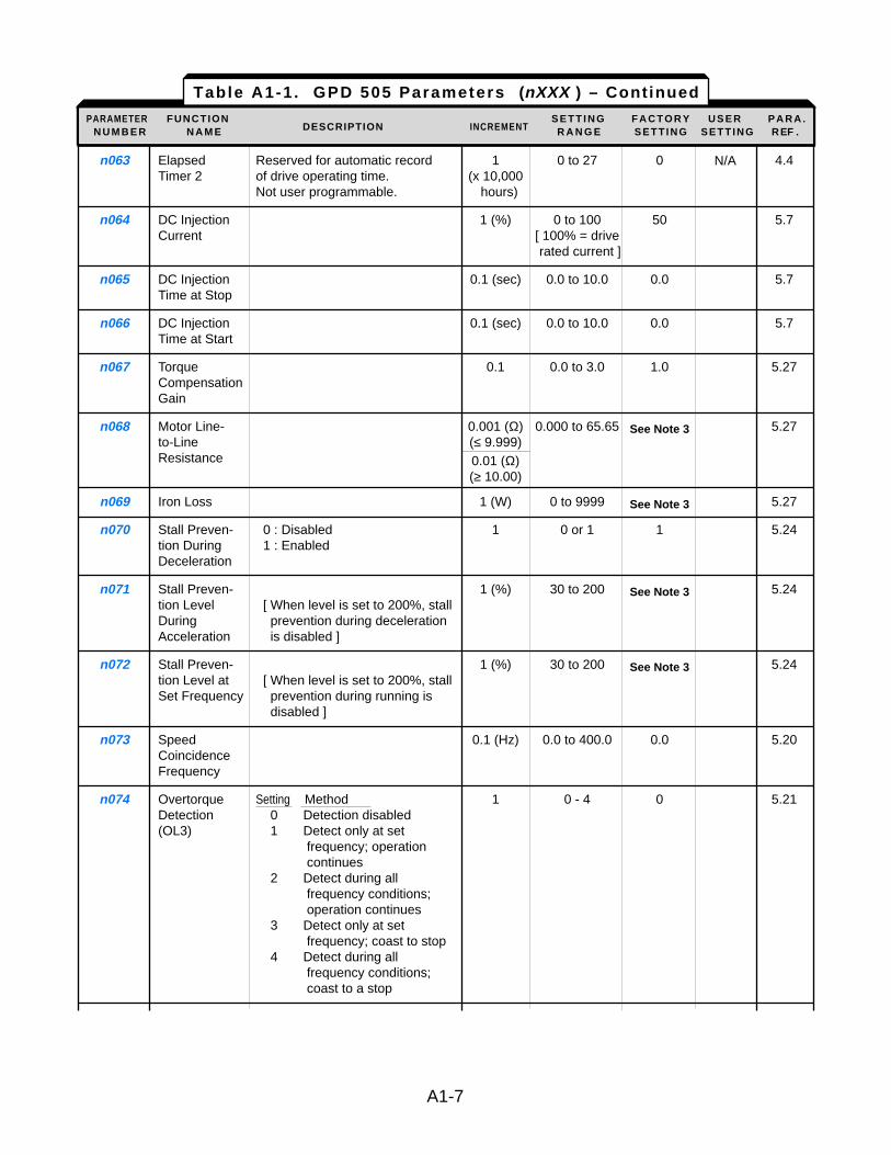
n063 Elapsed Reserved for automatic record 1 0 to 27 0 4.4Timer 2 of drive operating time. (x 10,000
Not user programmable. hours)
n064 DC Injection 1 (%) 0 to 100 50 5.7Current [ 100% = drive
rated current ]
n065 DC Injection 0.1 (sec) 0.0 to 10.0 0.0 5.7Time at Stop
n066 DC Injection 0.1 (sec) 0.0 to 10.0 0.0 5.7Time at Start
n067 Torque 0.1 0.0 to 3.0 1.0 5.27Compensation Gain
n068 Motor Line- 0.001 (Ω) 0.000 to 65.65 See Note 3 5.27to-Line (≤ 9.999)Resistance 0.01 (Ω)
(≥ 10.00)
n069 Iron Loss 1 (W) 0 to 9999 See Note 3 5.27
n070 Stall Preven- 0 : Disabled 1 0 or 1 1 5.24tion During 1 : EnabledDeceleration
n071 Stall Preven- 1 (%) 30 to 200 See Note 3 5.24tion Level [ When level is set to 200%, stall During prevention during deceleration Acceleration is disabled ]
n072 Stall Preven- 1 (%) 30 to 200 See Note 3 5.24tion Level at [ When level is set to 200%, stall Set Frequency prevention during running is
disabled ]
n073 Speed 0.1 (Hz) 0.0 to 400.0 0.0 5.20Coincidence Frequency
n074 Overtorque Setting Method 1 0 - 4 0 5.21Detection 0 Detection disabled(OL3) 1 Detect only at set
frequency; operation continues
2 Detect during all frequency conditions; operation continues
3 Detect only at set frequency; coast to stop
4 Detect during all frequency conditions; coast to a stop
Table A1-1 . GPD 505 Parameters (nXXX ) – Continued
PARAMETER FUNCTION S E T T I N G F A C T O R Y U S E R P A R A .N U M B E R N A M E DESCRIPTION INCREMENT R A N G E SETT ING SETT ING REF .
A1-7
N/A
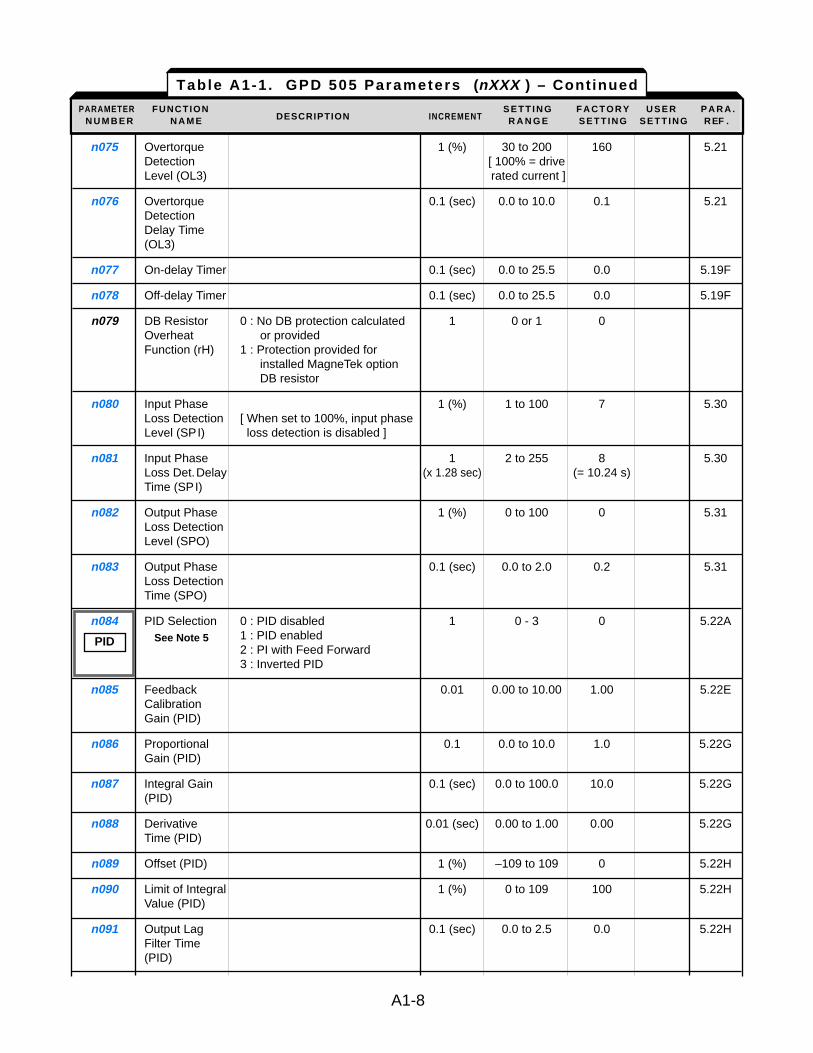
n075 Overtorque 1 (%) 30 to 200 160 5.21Detection [ 100% = drive Level (OL3) rated current ]
n076 Overtorque 0.1 (sec) 0.0 to 10.0 0.1 5.21Detection Delay Time (OL3)
n077 On-delay Timer 0.1 (sec) 0.0 to 25.5 0.0 5.19F
n078 Off-delay Timer 0.1 (sec) 0.0 to 25.5 0.0 5.19F
n079 DB Resistor 0 : No DB protection calculated 1 0 or 1 0Overheat or providedFunction (rH) 1 : Protection provided for
installed MagneTek option DB resistor
n080 Input Phase 1 (%) 1 to 100 7 5.30Loss Detection [ When set to 100%, input phase Level (SPI) loss detection is disabled ]
n081 Input Phase 1 2 to 255 8 5.30Loss Det.Delay (x 1.28 sec) (= 10.24 s)Time (SPI)
n082 Output Phase 1 (%) 0 to 100 0 5.31Loss Detection Level (SPO)
n083 Output Phase 0.1 (sec) 0.0 to 2.0 0.2 5.31Loss Detection Time (SPO)
n084 PID Selection 0 : PID disabled 1 0 - 3 0 5.22ASee Note 5 1 : PID enabled
2 : PI with Feed Forward3 : Inverted PID
n085 Feedback 0.01 0.00 to 10.00 1.00 5.22ECalibration Gain (PID)
n086 Proportional 0.1 0.0 to 10.0 1.0 5.22GGain (PID)
n087 Integral Gain 0.1 (sec) 0.0 to 100.0 10.0 5.22G(PID)
n088 Derivative 0.01 (sec) 0.00 to 1.00 0.00 5.22GTime (PID)
n089 Offset (PID) 1 (%) –109 to 109 0 5.22H
n090 Limit of Integral 1 (%) 0 to 109 100 5.22HValue (PID)
n091 Output Lag 0.1 (sec) 0.0 to 2.5 0.0 5.22HFilter Time (PID)
Table A1-1 . GPD 505 Parameters (nXXX ) – Continued
PARAMETER FUNCTION S E T T I N G F A C T O R Y U S E R P A R A .N U M B E R N A M E DESCRIPTION INCREMENT R A N G E SETT ING SETT ING REF .
A1-8
PID
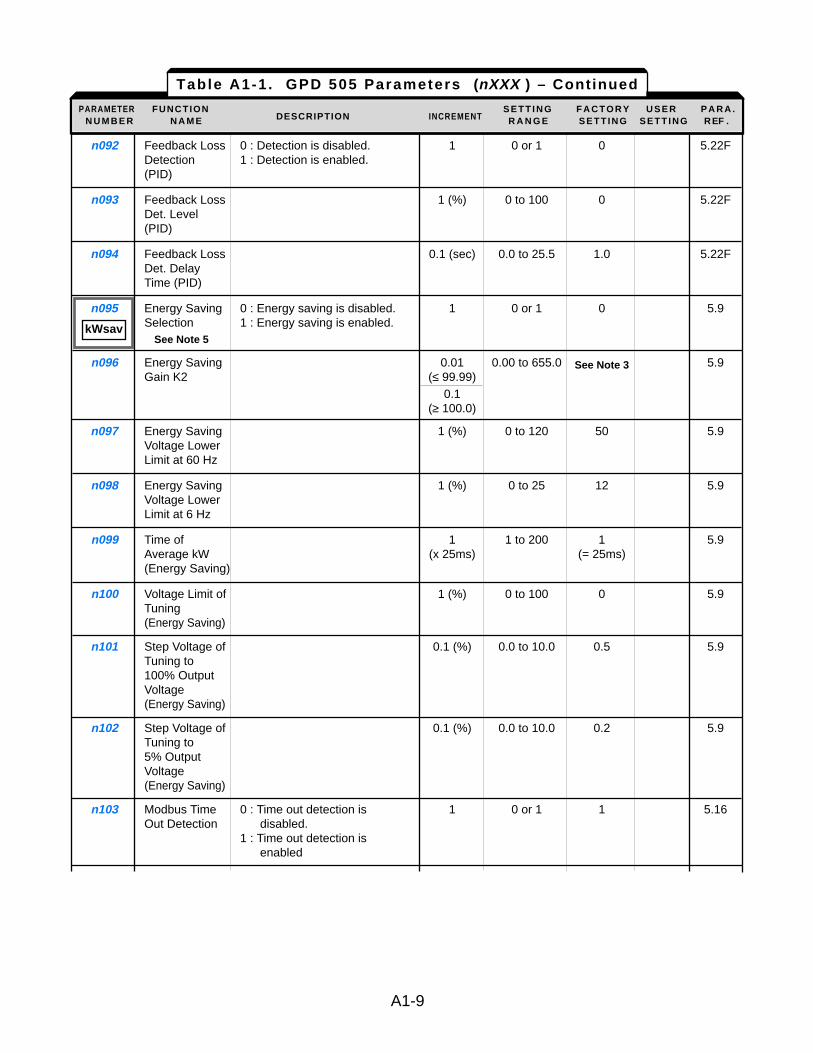
n092 Feedback Loss 0 : Detection is disabled. 1 0 or 1 0 5.22FDetection 1 : Detection is enabled.(PID)
n093 Feedback Loss 1 (%) 0 to 100 0 5.22FDet. Level (PID)
n094 Feedback Loss 0.1 (sec) 0.0 to 25.5 1.0 5.22FDet. Delay Time (PID)
n095 Energy Saving 0 : Energy saving is disabled. 1 0 or 1 0 5.9Selection 1 : Energy saving is enabled.
See Note 5
n096 Energy Saving 0.01 0.00 to 655.0 See Note 3 5.9Gain K2 (≤ 99.99)
0.1(≥ 100.0)
n097 Energy Saving 1 (%) 0 to 120 50 5.9Voltage Lower Limit at 60 Hz
n098 Energy Saving 1 (%) 0 to 25 12 5.9Voltage Lower Limit at 6 Hz
n099 Time of 1 1 to 200 1 5.9Average kW (x 25ms) (= 25ms)(Energy Saving)
n100 Voltage Limit of 1 (%) 0 to 100 0 5.9Tuning (Energy Saving)
n101 Step Voltage of 0.1 (%) 0.0 to 10.0 0.5 5.9Tuning to 100% Output Voltage(Energy Saving)
n102 Step Voltage of 0.1 (%) 0.0 to 10.0 0.2 5.9Tuning to 5% Output Voltage(Energy Saving)
n103 Modbus Time 0 : Time out detection is 1 0 or 1 1 5.16Out Detection disabled.
1 : Time out detection is enabled
Table A1-1 . GPD 505 Parameters (nXXX ) – Continued
PARAMETER FUNCTION S E T T I N G F A C T O R Y U S E R P A R A .N U M B E R N A M E DESCRIPTION INCREMENT R A N G E SETT ING SETT ING REF .
A1-9
kWsav
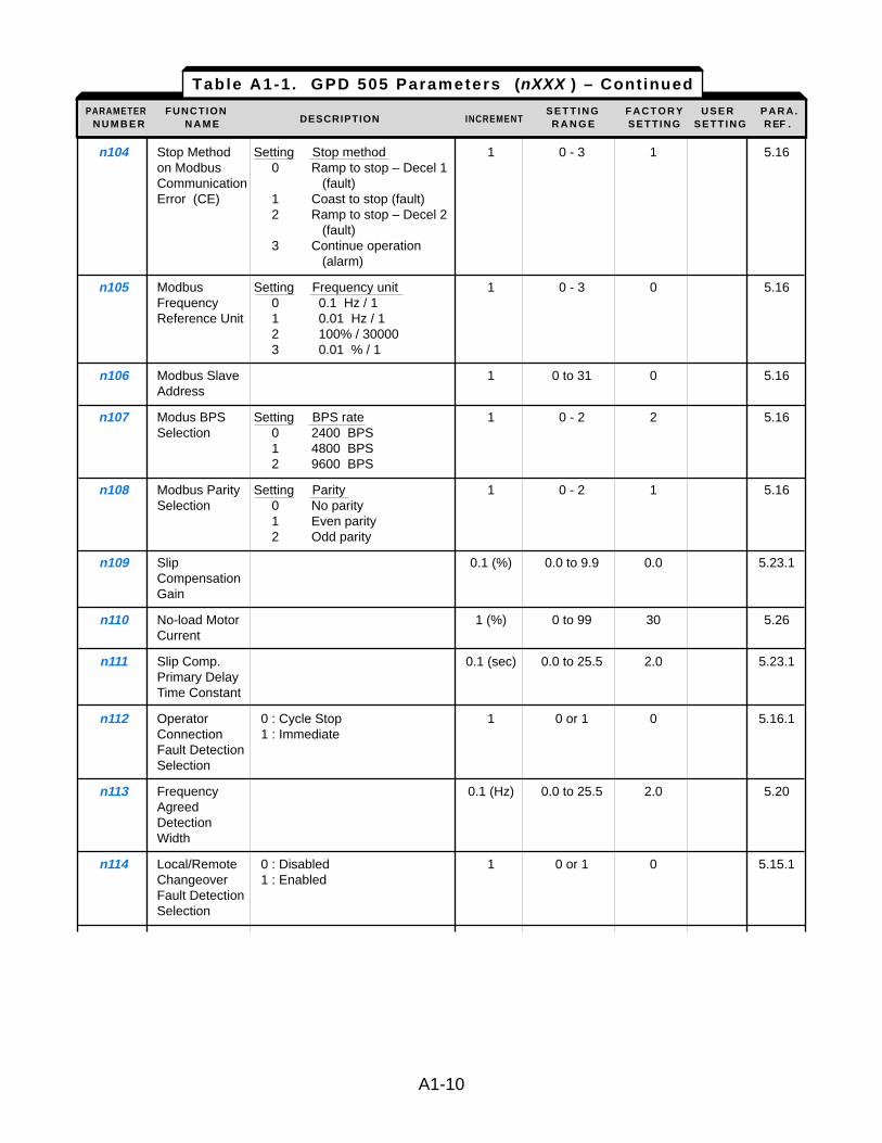
n104 Stop Method Setting Stop method 1 0 - 3 1 5.16on Modbus 0 Ramp to stop – Decel 1 Communication (fault)Error (CE) 1 Coast to stop (fault)
2 Ramp to stop – Decel 2 (fault)
3 Continue operation (alarm)
n105 Modbus Setting Frequency unit 1 0 - 3 0 5.16Frequency 0 0.1 Hz / 1Reference Unit 1 0.01 Hz / 1
2 100% / 300003 0.01 % / 1
n106 Modbus Slave 1 0 to 31 0 5.16Address
n107 Modus BPS Setting BPS rate 1 0 - 2 2 5.16Selection 0 2400 BPS
1 4800 BPS2 9600 BPS
n108 Modbus Parity Setting Parity 1 0 - 2 1 5.16Selection 0 No parity
1 Even parity2 Odd parity
n109 Slip 0.1 (%) 0.0 to 9.9 0.0 5.23.1CompensationGain
n110 No-load Motor 1 (%) 0 to 99 30 5.26Current
n111 Slip Comp. 0.1 (sec) 0.0 to 25.5 2.0 5.23.1Primary DelayTime Constant
n112 Operator 0 : Cycle Stop 1 0 or 1 0 5.16.1Connection 1 : ImmediateFault DetectionSelection
n113 Frequency 0.1 (Hz) 0.0 to 25.5 2.0 5.20AgreedDetectionWidth
n114 Local/Remote 0 : Disabled 1 0 or 1 0 5.15.1Changeover 1 : EnabledFault DetectionSelection
A1-10
Table A1-1 . GPD 505 Parameters (nXXX ) – Continued
PARAMETER FUNCTION S E T T I N G F A C T O R Y U S E R P A R A .N U M B E R N A M E DESCRIPTION INCREMENT R A N G E SETT ING SETT ING REF .
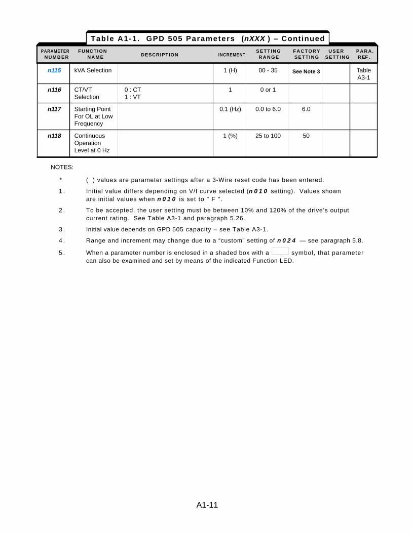
n115 kVA Selection 1 (H) 00 - 35 See Note 3 TableA3-1
n116 CT/VT 0 : CT 1 0 or 1Selection 1 : VT
n117 Starting Point 0.1 (Hz) 0.0 to 6.0 6.0For OL at LowFrequency
n118 Continuous 1 (%) 25 to 100 50Operation Level at 0 Hz
NOTES:
* ( ) values are parameter settings after a 3-Wire reset code has been entered.
1 . Initial value differs depending on V/f curve selected (n 0 1 0 setting). Values shown are initial values when n 0 1 0 is set to " F ".
2 . To be accepted, the user setting must be between 10% and 120% of the drive’s output current rating. See Table A3-1 and paragraph 5.26.
3 . Initial value depends on GPD 505 capacity – see Table A3-1.
4 . Range and increment may change due to a “custom” setting of n 0 2 4 — see paragraph 5.8.
5 . When a parameter number is enclosed in a shaded box with a symbol, that parameter can also be examined and set by means of the indicated Function LED.
A1-11
Table A1-1 . GPD 505 Parameters (nXXX ) – Continued
PARAMETER FUNCTION S E T T I N G F A C T O R Y U S E R P A R A .N U M B E R N A M E DESCRIPTION INCREMENT R A N G E SETT ING SETT ING REF .
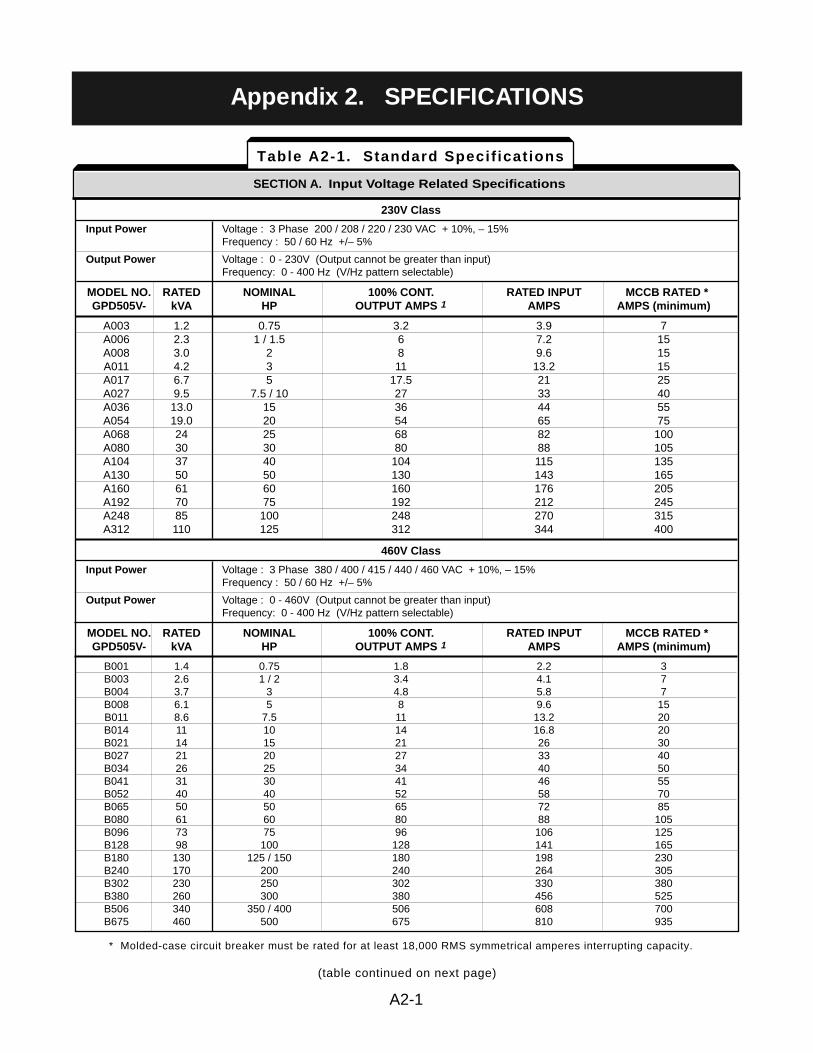
SECTION A. Input Voltage Related Specifications
Table A2-1. Standard Specif icat ions
A2-1
(table continued on next page)
Appendix 2. SPECIFICATIONS
230V Class
Input Power Voltage : 3 Phase 200 / 208 / 220 / 230 VAC + 10%, – 15%Frequency : 50 / 60 Hz +/– 5%
Output Power Voltage : 0 - 230V (Output cannot be greater than input)Frequency: 0 - 400 Hz (V/Hz pattern selectable)
MODEL NO. RATED NOMINAL 100% CONT. RATED INPUT MCCB RATED *GPD505V- kVA HP OUTPUT AMPS 1 AMPS AMPS (minimum)
A003 1.2 0.75 3.2 3.9 7A006 2.3 1 / 1.5 6 7.2 15A008 3.0 2 8 9.6 15A011 4.2 3 11 13.2 15A017 6.7 5 17.5 21 25A027 9.5 7.5 / 10 27 33 40A036 13.0 15 36 44 55A054 19.0 20 54 65 75A068 24 25 68 82 100A080 30 30 80 88 105A104 37 40 104 115 135A130 50 50 130 143 165A160 61 60 160 176 205A192 70 75 192 212 245A248 85 100 248 270 315A312 110 125 312 344 400
460V Class
Input Power Voltage : 3 Phase 380 / 400 / 415 / 440 / 460 VAC + 10%, – 15%Frequency : 50 / 60 Hz +/– 5%
Output Power Voltage : 0 - 460V (Output cannot be greater than input)Frequency: 0 - 400 Hz (V/Hz pattern selectable)
MODEL NO. RATED NOMINAL 100% CONT. RATED INPUT MCCB RATED *GPD505V- kVA HP OUTPUT AMPS 1 AMPS AMPS (minimum)
B001 1.4 0.75 1.8 2.2 3B003 2.6 1 / 2 3.4 4.1 7B004 3.7 3 4.8 5.8 7B008 6.1 5 8 9.6 15B011 8.6 7.5 11 13.2 20B014 11 10 14 16.8 20B021 14 15 21 26 30B027 21 20 27 33 40B034 26 25 34 40 50B041 31 30 41 46 55B052 40 40 52 58 70B065 50 50 65 72 85B080 61 60 80 88 105B096 73 75 96 106 125B128 98 100 128 141 165B180 130 125 / 150 180 198 230B240 170 200 240 264 305B302 230 250 302 330 380B380 260 300 380 456 525B506 340 350 / 400 506 608 700B675 460 500 675 810 935
* Molded-case circuit breaker must be rated for at least 18,000 RMS symmetrical amperes interrupting capacity.
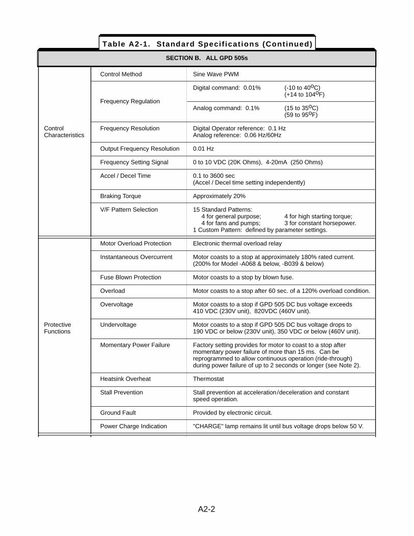
SECTION C. ALL GPD 505s
Control Method Sine Wave PWM
Digital command: 0.01% (-10 to 40oC)(+14 to 104oF)
Frequency RegulationAnalog command: 0.1% (15 to 35oC)
(59 to 95oF)
Control Frequency Resolution Digital Operator reference: 0.1 HzCharacteristics Analog reference: 0.06 Hz/60Hz
Output Frequency Resolution 0.01 Hz
Frequency Setting Signal 0 to 10 VDC (20K Ohms), 4-20mA (250 Ohms)
Accel / Decel Time 0.1 to 3600 sec(Accel / Decel time setting independently)
Braking Torque Approximately 20%
V/F Pattern Selection 15 Standard Patterns:4 for general purpose; 4 for high starting torque;4 for fans and pumps; 3 for constant horsepower.
1 Custom Pattern: defined by parameter settings.
Motor Overload Protection Electronic thermal overload relay
Instantaneous Overcurrent Motor coasts to a stop at approximately 180% rated current.(200% for Model -A068 & below, -B039 & below)
Fuse Blown Protection Motor coasts to a stop by blown fuse.
Overload Motor coasts to a stop after 60 sec. of a 120% overload condition.
Overvoltage Motor coasts to a stop if GPD 505 DC bus voltage exceeds410 VDC (230V unit), 820VDC (460V unit).
Protective Undervoltage Motor coasts to a stop if GPD 505 DC bus voltage drops toFunctions 190 VDC or below (230V unit), 350 VDC or below (460V unit).
Momentary Power Failure Factory setting provides for motor to coast to a stop aftermomentary power failure of more than 15 ms. Can bereprogrammed to allow continuous operation (ride-through)during power failure of up to 2 seconds or longer (see Note 2).
Heatsink Overheat Thermostat
Stall Prevention Stall prevention at acceleration/deceleration and constantspeed operation.
Ground Fault Provided by electronic circuit.
Power Charge Indication "CHARGE" lamp remains lit until bus voltage drops below 50 V.
SECTION B. ALL GPD 505s
Table A2-1. Standard Specif icat ions (Continued)
A2-2
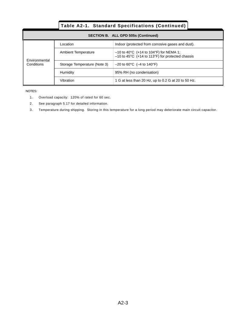
SECTION C. ALL GPD 505s (CONTINUED)
Location Indoor (protected from corrosive gases and dust).
Ambient Temperature –10 to 40°C (+14 to 104°F) for NEMA 1;–10 to 45°C (+14 to 113°F) for protected chassis
EnvironmentalConditions Storage Temperature (Note 3) –20 to 60°C (–4 to 140°F)
Humidity 95% RH (no condensation)
Vibration 1 G at less than 20 Hz, up to 0.2 G at 20 to 50 Hz.
SECTION B. ALL GPD 505s (Continued)
NOTES:
1 . Overload capacity: 120% of rated for 60 sec.
2 . See paragraph 5.17 for detailed information.
3 . Temperature during shipping. Storing in this temperature for a long period may deteriorate main circuit capacitor.
Table A2-1. Standard Specif icat ions (Continued)
A2-3
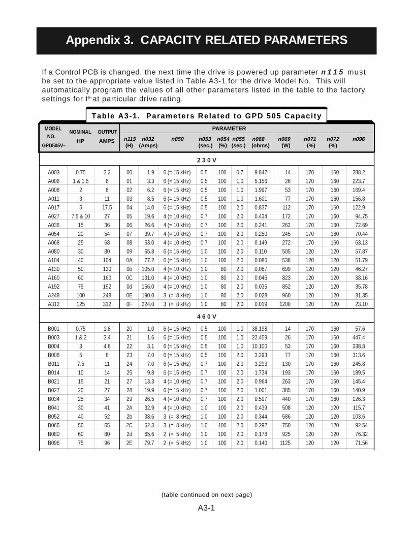
If a Control PCB is changed, the next time the drive is powered up parameter n 1 1 5 mustbe set to the appropriate value listed in Table A3-1 for the drive Model No. This willautomatically program the values of all other parameters listed in the table to the factorysettings for that particular drive rating.
2 3 0 V
A003 0.75 3.2 00 1.9 6 (= 15 kHz) 0.5 100 0.7 9.842 14 170 160 288.2A006 1 & 1.5 6 01 3.3 6 (= 15 kHz) 0.5 100 1.0 5.156 26 170 160 223.7A008 2 8 02 6.2 6 (= 15 kHz) 0.5 100 1.0 1.997 53 170 160 169.4A011 3 11 03 8.5 6 (= 15 kHz) 0.5 100 1.0 1.601 77 170 160 156.8A017 5 17.5 04 14.0 6 (= 15 kHz) 0.5 100 2.0 0.837 112 170 160 122.9A027 7.5 & 10 27 05 19.6 4 (= 10 kHz) 0.7 100 2.0 0.434 172 170 160 94.75A036 15 36 06 26.6 4 (= 10 kHz) 0.7 100 2.0 0.241 262 170 160 72.69A054 20 54 07 39.7 4 (= 10 kHz) 0.7 100 2.0 0.250 245 170 160 70.44A068 25 68 08 53.0 4 (= 10 kHz) 0.7 100 2.0 0.149 272 170 160 63.13A080 30 80 09 65.8 6 (= 15 kHz) 1.0 100 2.0 0.110 505 120 120 57.87A104 40 104 0A 77.2 6 (= 15 kHz) 1.0 100 2.0 0.086 538 120 120 51.79A130 50 130 0b 105.0 4 (= 10 kHz) 1.0 80 2.0 0.067 699 120 120 46.27A160 60 160 0C 131.0 4 (= 10 kHz) 1.0 80 2.0 0.045 823 120 120 38.16A192 75 192 0d 156.0 4 (= 10 kHz) 1.0 80 2.0 0.035 852 120 120 35.78A248 100 248 0E 190.0 3 (= 8 kHz) 1.0 80 2.0 0.028 960 120 120 31.35A312 125 312 0F 224.0 3 (= 8 kHz) 1.0 80 2.0 0.019 1200 120 120 23.10
4 6 0 V
B001 0.75 1.8 20 1.0 6 (= 15 kHz) 0.5 100 1.0 38.198 14 170 160 57.6B003 1 & 2 3.4 21 1.6 6 (= 15 kHz) 0.5 100 1.0 22.459 26 170 160 447.4B004 3 4.8 22 3.1 6 (= 15 kHz) 0.5 100 1.0 10.100 53 170 160 338.8B008 5 8 23 7.0 6 (= 15 kHz) 0.5 100 2.0 3.293 77 170 160 313.6B011 7.5 11 24 7.0 6 (= 15 kHz) 0.7 100 2.0 3.293 130 170 160 245.8B014 10 14 25 9.8 6 (= 15 kHz) 0.7 100 2.0 1.734 193 170 160 189.5B021 15 21 27 13.3 4 (= 10 kHz) 0.7 100 2.0 0.964 263 170 160 145.4B027 20 27 28 19.9 6 (= 15 kHz) 0.7 100 2.0 1.001 385 170 160 140.9B034 25 34 29 26.5 4 (= 10 kHz) 0.7 100 2.0 0.597 440 170 160 126.3B041 30 41 2A 32.9 4 (= 10 kHz) 1.0 100 2.0 0.439 508 120 120 115.7B052 40 52 2b 38.6 3 (= 8 kHz) 1.0 100 2.0 0.344 586 120 120 103.6B065 50 65 2C 52.3 3 (= 8 kHz) 1.0 100 2.0 0.292 750 120 120 92.54B080 60 80 2d 65.6 2 (= 5 kHz) 1.0 100 2.0 0.178 925 120 120 76.32B096 75 96 2E 79.7 2 (= 5 kHz) 1.0 100 2.0 0.140 1125 120 120 71.56
A3-1
Appendix 3. CAPACITY RELATED PARAMETERS
(table continued on next page)
Table A3-1. Parameters Related to GPD 505 Capacity
MODEL NOMINAL OUTPUT
PARAMETERNO.
HP AMPS n115 n032 n050 n053 n054 n055 n068 n069 n071 n072 n096GPD505V– (H) (Amps) (sec.) (%) (sec.) (ohms) (W) (%) (%)
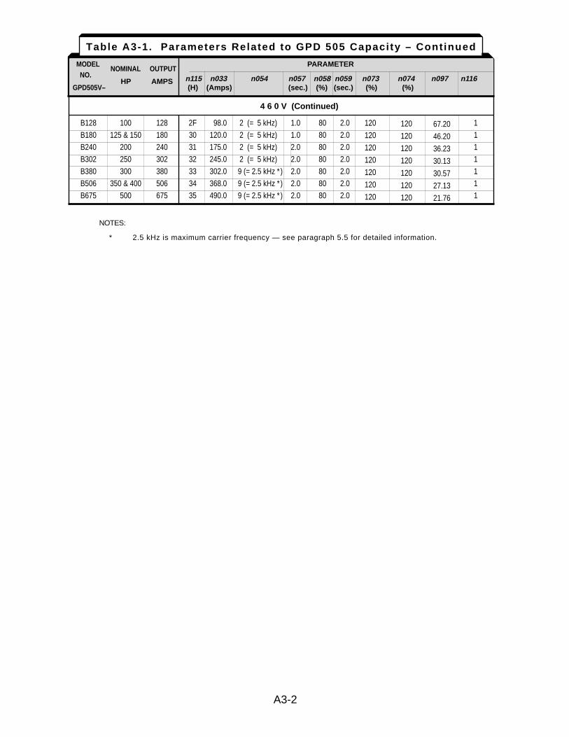
4 6 0 V (Continued)
B128 100 128 2F 98.0 2 (= 5 kHz) 1.0 80 2.0 1B180 125 & 150 180 30 120.0 2 (= 5 kHz) 1.0 80 2.0 1B240 200 240 31 175.0 2 (= 5 kHz) 2.0 80 2.0 1B302 250 302 32 245.0 2 (= 5 kHz) 2.0 80 2.0 1B380 300 380 33 302.0 9 (= 2.5 kHz * ) 2.0 80 2.0 1B506 350 & 400 506 34 368.0 9 (= 2.5 kHz * ) 2.0 80 2.0 1B675 500 675 35 490.0 9 (= 2.5 kHz * ) 2.0 80 2.0 1
NOTES:
* 2.5 kHz is maximum carrier frequency — see paragraph 5.5 for detailed information.
Table A3-1. Parameters Related to GPD 505 Capacity – Continued
MODEL NOMINAL OUTPUT
PARAMETERNO.
HP AMPS n115 n033 n054 n057 n058 n059 n073 n074 n097 n116GPD505V– (H) (Amps) (sec.) (%) (sec.) (%) (%)
A3-2
120
120
120
120
120
120
120
120
120
120
120
120
120
120
67.20
46.20
36.23
30.13
30.57
27.13
21.76
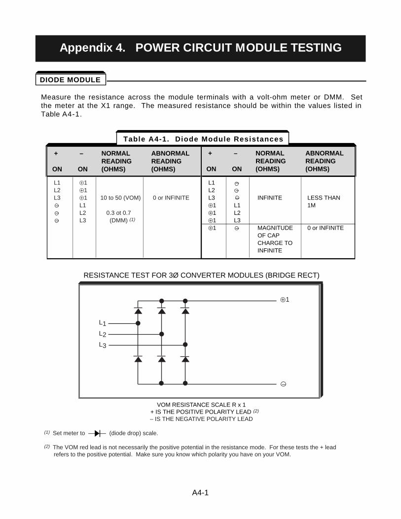
Measure the resistance across the module terminals with a volt-ohm meter or DMM. Setthe meter at the X1 range. The measured resistance should be within the values listed inTable A4-1.
RESISTANCE TEST FOR 3Ø CONVERTER MODULES (BRIDGE RECT)
VOM RESISTANCE SCALE R x 1+ IS THE POSITIVE POLARITY LEAD (2)
– IS THE NEGATIVE POLARITY LEAD
(1) Set meter to ——— (diode drop) scale.
(2) The VOM red lead is not necessarily the positive potential in the resistance mode. For these tests the + lead refers to the positive potential. Make sure you know which polarity you have on your VOM.
+ – NORMAL ABNORMALREADING READING
ON ON (OHMS) (OHMS)
L1 Å1L2 Å1L3 Å1 10 to 50 (VOM) 0 or INFINITE– L1– L2 0.3 ot 0.7 – L3 (DMM) (1)
+ – NORMAL ABNORMALREADING READING
ON ON (OHMS) (OHMS)
+ – NORMAL ABNORMALREADING READING
ON ON (OHMS) (OHMS)
L1 –L2 –L3 – INFINITE LESS THANÅ1 L1 1MÅ1 L2Å1 L3Å1 – MAGNITUDE 0 or INFINITE
OF CAPCHARGE TOINFINITE
+ – NORMAL ABNORMALREADING READING
ON ON (OHMS) (OHMS)
L1
L2
L3
ÅÅ1
–
Table A4-1. Diode Module Resistances
A4-1
Appendix 4. POWER CIRCUIT MODULE TESTING
DIODE MODULE
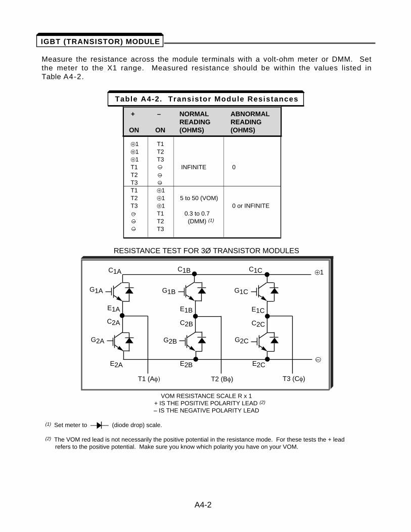
Measure the resistance across the module terminals with a volt-ohm meter or DMM. Setthe meter to the X1 range. Measured resistance should be within the values listed inTable A4-2.
RESISTANCE TEST FOR 3Ø TRANSISTOR MODULES
VOM RESISTANCE SCALE R x 1+ IS THE POSITIVE POLARITY LEAD (2)
– IS THE NEGATIVE POLARITY LEAD
(1) Set meter to ——— (diode drop) scale.
(2) The VOM red lead is not necessarily the positive potential in the resistance mode. For these tests the + lead refers to the positive potential. Make sure you know which polarity you have on your VOM.
A4-2
+ – NORMAL ABNORMALREADING READING
ON ON (OHMS) (OHMS)
Å1 T1Å1 T2Å1 T3T1 – INFINITE 0T2 –T3 –T1 Å1T2 Å1 5 to 50 (VOM)T3 Å1 0 or INFINITE– T1 0.3 to 0.7– T2 (DMM) (1)
– T3
+ – NORMAL ABNORMALREADING READING
ON ON (OHMS) (OHMS)
Table A4-2. Transistor Module Resistances
G1A
E1A E1B E1C
C2A C2B C2C
G1B G1C
G2A
E2A E2B E2C
G2B G2C
C1A C1B C1C
T1 (Af) T2 (Bf) T3 (Cf)
Å1
–
IGBT (TRANSISTOR) MODULE
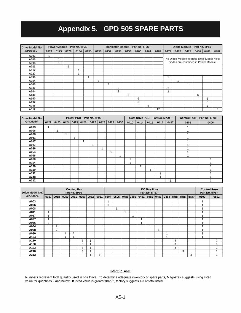
A5-1
Appendix 5. GPD 505 SPARE PARTS
Drive Model No.GPD505V–
Power Module Part No. 5P30– Transistor Module Part No. 5P30– Diode Module Part No. 5P50–
A003A006A008A011A017A027A036A054A068A080A104A130A160A192A248A312
11
0154
1
0174
11
0175
1
0178
1
0155
3
0156
3
0157
33
0158
6
0159
66
0160
6
0161
1
22
0477
1
0478
1
0479
6
0480
666
0481
6
0482
12
0182
No Diode Module in these Drive Model No's;diodes are contained in Power Module.
Drive Model No.GPD505V-
Power PCB Part No. 5P90– Gate Drive PCB Part No. 5P90– Control PCB Part No. 5P90–
A003A006A008A011A017A027A036A054A068A080A104A130A160A192A248A312
1
0426
1
0427
1
0428
1
0429
1
0430
11
0410
1
0414
11
0416
1
0417
111111111
0409
1111111
0406
1
0415
1
0422
1
0423
1
0424
1
0425
IMPORTANT
Numbers represent total quantity used in one Drive. To determine adequate inventory of spare parts, MagneTek suggests using listedvalue for quantities 2 and below. If listed value is greater than 2, factory suggests 1/3 of total listed.
Drive Model No.GPD505V-
Cooling FanPart No. 5P16–
DC Bus FusePart No. 5P17–
Control FusePart No. 5P17-
A003A006A008A011A017A027A036A054A068A080A104A130A160A192A248A312
1112
0057
22
0058
11
0059
11
0061
3333
0050
11111
0062
3
0051
11
0481
1
0482
11111111111
0500
11111
0502
1
0480
1
0505
1
0488
11
0504
1
0483
11
0484
3
0486
3
0487
333
0485
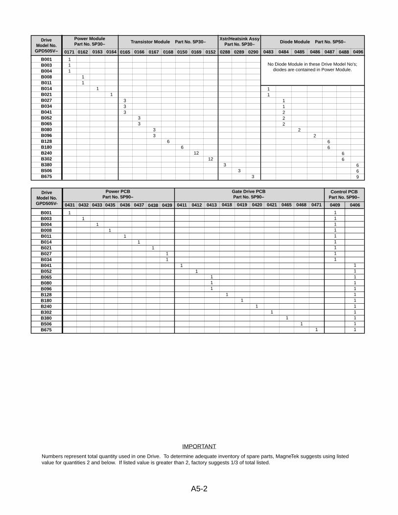
A5-2
IMPORTANT
Numbers represent total quantity used in one Drive. To determine adequate inventory of spare parts, MagneTek suggests using listedvalue for quantities 2 and below. If listed value is greater than 2, factory suggests 1/3 of total listed.
DriveModel No.
GPD505V–
Power ModulePart No. 5P30– Transistor Module Part No. 5P30–
Xstr/Heatsink AssyPart No. 5P30– Diode Module Part No. 5P50–
B001B003B004B008B011B014B021B027B034B041B052B065B080B096B128B180B240B302B380B506B675
11
0162
111
0171
1
0163
1
0164
333
0165
33
0166
33
0167
6
0168
6
0150
12
0169
11
0483
11222
0484
2
0485
2
0486
66
0487
66
0488
669
0496
12
0152
No Diode Module in these Drive Model No's;diodes are contained in Power Module.
33
02890288
3
0290
DriveModel No.GPD505V-
Power PCB Part No. 5P90–
Gate Drive PCB Part No. 5P90–
Control PCB Part No. 5P90–
B001B003B004B008B011B014B021B027B034B041B052B065B080B096B128B180B240B302B380B506B675
1
0435
1
0436
1
0437
1
0438
11
0439
1
0431
1
0432
1
0433
1
0411
1
0412
1
0418
1
0419
1
0420
1
0421
1
0465
1
0468
1
0471
111111111
0409
111111111111
0406
111
0413
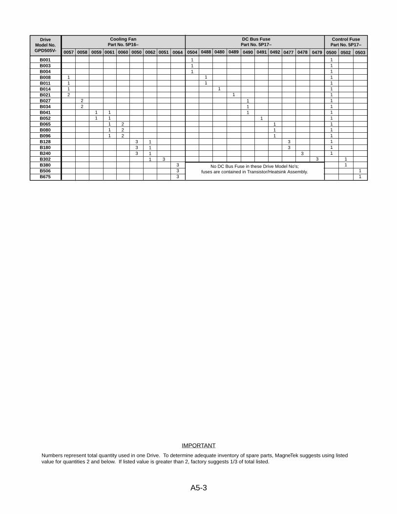
11
11
A5-3
IMPORTANT
Numbers represent total quantity used in one Drive. To determine adequate inventory of spare parts, MagneTek suggests using listedvalue for quantities 2 and below. If listed value is greater than 2, factory suggests 1/3 of total listed.
DriveModel No.GPD505V-
Cooling Fan Part No. 5P16–
DC Bus Fuse Part No. 5P17–
Control Fuse Part No. 5P17–
B001B003B004B008B011B014B021B027B034B041B052B065B080B096B128B180B240B302B380B506B675
1112
0057
22
0058
11
0059
11111
0061
333
0050
1111
0062
3
0051
333
0064
222
0060
11
0488
111
0504
1
0489
111
0490
11111111111111111
0500 0502 0503
1
0480
1
0491
111
0492
3
0478
3
0479
33
0477
No DC Bus Fuse in these Drive Model No's; fuses are contained in Transistor/Heatsink Assembly.
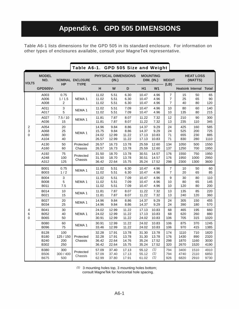
A6-1
Table A6-1 lists dimensions for the GPD 505 in its standard enclosure. For information onother types of enclosures available, consult your MagneTek representative.
Appendix 6. GPD 505 DIMENSIONS
A003 0.75 11.02 5.51 6.30 10.47 4.96 7 15 50 65A006 1 / 1.5 NEMA 1 11.02 5.51 6.30 10.47 4.96 7 25 65 90A008 2 11.02 5.51 6.30 10.47 4.96 7 40 80 120
A011 3NEMA 1
11.02 5.51 7.09 10.47 4.96 10 80 60 140A017 5 11.02 5.51 7.09 10.47 4.96 10 135 80 215
A027 7.5 / 10NEMA 1
11.81 7.87 8.07 11.22 7.32 12 210 90 300A036 15 11.81 7.87 8.07 11.22 7.32 13 235 110 345
2 A054 20 14.96 9.84 8.86 14.37 9.29 24 425 160 5853 A068 25
NEMA 115.75 9.84 8.86 14.37 9.29 24 525 200 725
0 A080 30 24.02 12.99 11.22 17.13 10.83 71 655 230 885A104 40 26.57 12.99 11.22 17.13 10.83 71 830 280 1110
A130 50 Protected 26.57 16.73 13.78 25.59 12.60 134 1050 500 1550A160 60 Chassis 26.57 16.73 13.78 25.59 12.60 137 1250 700 1950
A192 75Protected
31.50 18.70 13.78 30.51 14.57 176 1550 750 1950A248 100
Chassis31.50 18.70 13.78 30.51 14.57 176 1950 1000 2950
A312 125 36.42 22.64 15.75 35.24 17.52 298 2300 1300 3600
B001 0.75NEMA 1
11.02 5.51 6.30 10.47 4.96 7 10 50 60B003 1 / 2 11.02 5.51 6.30 10.47 4.96 7 20 65 85
B004 3 11.02 5.51 7.09 10.47 4.96 9 30 80 110B008 5 NEMA 1 11.02 5.51 7.09 10.47 4.96 10 80 65 145B011 7.5 11.02 5.51 7.09 10.47 4.96 10 120 80 200
B014 10NEMA 1
11.81 7.87 8.07 11.22 7.32 13 135 85 220B021 15 11.81 7.87 8.07 11.22 7.32 13 240 120 360
B027 20NEMA 1
14.96 9.84 8.86 14.37 9.29 24 305 150 455B034 25 14.96 9.84 8.86 14.37 9.29 24 390 180 570
4 B041 30 24.02 12.99 11.22 17.13 10.83 68 465 195 6606 B052 40 NEMA 1 24.02 12.99 11.22 17.13 10.83 68 620 260 8800 B065 50 30.91 12.99 11.22 24.02 10.83 106 705 315 1020
B080 60NEMA 1
30.91 12.99 11.22 24.02 10.83 106 875 370 1245B096 75 33.46 12.99 11.22 24.02 10.83 106 970 415 1385
B128 100 32.28 17.91 13.78 31.30 13.78 174 1110 710 1820B180 125 / 150 Protected 32.28 17.91 13.78 31.30 13.78 176 1430 890 2320B240 200 Chassis 36.42 22.64 14.76 35.24 17.52 298 1870 1160 3030B302 250 36.42 22.64 15.75 35.24 17.52 320 2670 1520 4190
B380 300Protected
57.09 37.40 17.13 55.12 (1) 794 3400 1510 4910B506 300 / 400
Chassis57.09 37.40 17.13 55.12 (1) 794 4740 2110 6850
B675 500 62.99 37.80 17.91 61.02 (1) 926 6820 2910 9730
MODEL PHYSICAL DIMENSIONS MOUNTING HEAT LOSS NO. NOMINAL ENCLOSURE (IN.) DIM. (IN.) WEIGHT (WATTS)
VOLTS HP TYPE (LB)GPD505V- H W D H1 W1 Heatsink Internal Total
Table A6-1. GPD 505 Size and Weight
(1) 3 mounting holes top, 3 mounting holes bottom;consult MagneTek for horizontal hole spacing.
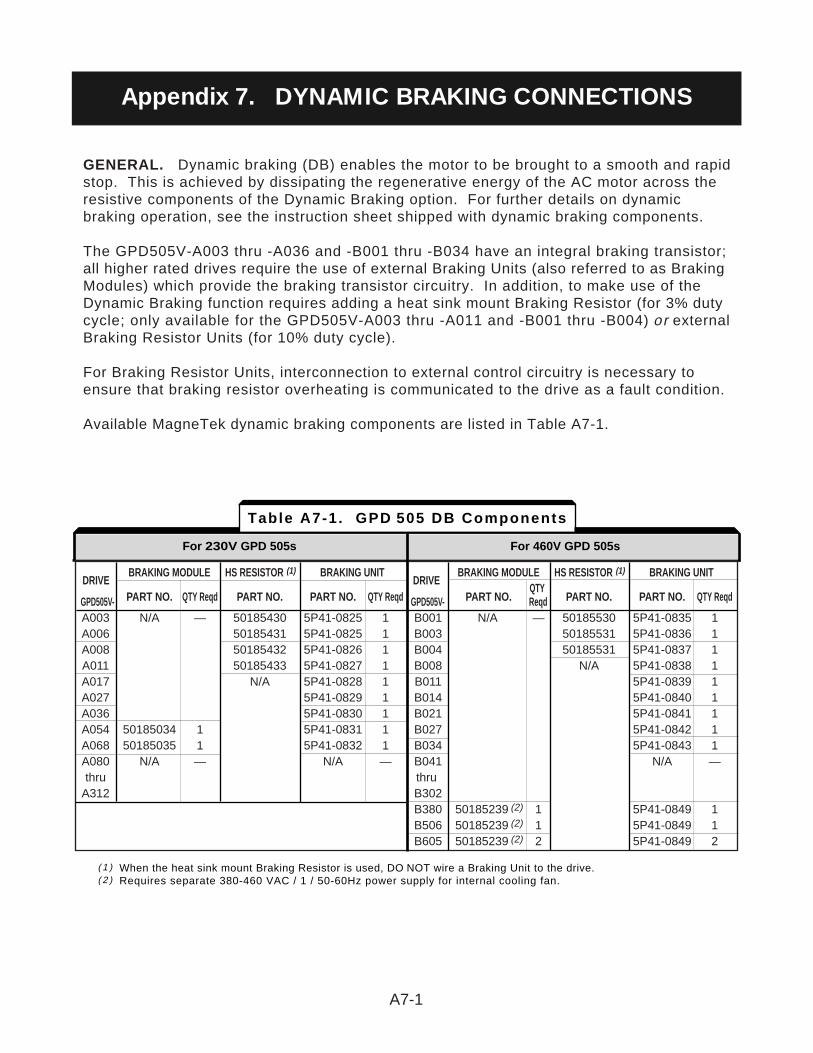
GENERAL. Dynamic braking (DB) enables the motor to be brought to a smooth and rapidstop. This is achieved by dissipating the regenerative energy of the AC motor across theresistive components of the Dynamic Braking option. For further details on dynamicbraking operation, see the instruction sheet shipped with dynamic braking components.
The GPD505V-A003 thru -A036 and -B001 thru -B034 have an integral braking transistor;all higher rated drives require the use of external Braking Units (also referred to as BrakingModules) which provide the braking transistor circuitry. In addition, to make use of theDynamic Braking function requires adding a heat sink mount Braking Resistor (for 3% dutycycle; only available for the GPD505V-A003 thru -A011 and -B001 thru -B004) or externalBraking Resistor Units (for 10% duty cycle).
For Braking Resistor Units, interconnection to external control circuitry is necessary toensure that braking resistor overheating is communicated to the drive as a fault condition.
Available MagneTek dynamic braking components are listed in Table A7-1.
A7-1
DRIVEBRAKING MODULE HS RESISTOR (1) BRAKING UNIT
DRIVEBRAKING MODULE HS RESISTOR (1) BRAKING UNIT
PART NO. QTY Reqd PART NO. PART NO. QTY Reqd PART NO.QTY
PART NO. PART NO. QTY ReqdGPD505V- GPD505V- ReqdA003 N/A — 50185430 5P41-0825 1 B001 N/A — 50185530 5P41-0835 1A006 50185431 5P41-0825 1 B003 50185531 5P41-0836 1A008 50185432 5P41-0826 1 B004 50185531 5P41-0837 1A011 50185433 5P41-0827 1 B008 N/A 5P41-0838 1A017 N/A 5P41-0828 1 B011 5P41-0839 1A027 5P41-0829 1 B014 5P41-0840 1A036 5P41-0830 1 B021 5P41-0841 1A054 50185034 1 5P41-0831 1 B027 5P41-0842 1A068 50185035 1 5P41-0832 1 B034 5P41-0843 1A080 N/A — N/A — B041 N/A —thru thru
A312 B302B380 50185239 (2) 1 5P41-0849 1B506 50185239 (2) 1 5P41-0849 1B605 50185239 (2) 2 5P41-0849 2
For 230V GPD 505s For 460V GPD 505s
Table A7-1. GPD 505 DB Components
( 1 ) When the heat sink mount Braking Resistor is used, DO NOT wire a Braking Unit to the drive.( 2 ) Requires separate 380-460 VAC / 1 / 50-60Hz power supply for internal cooling fan.
Appendix 7. DYNAMIC BRAKING CONNECTIONS
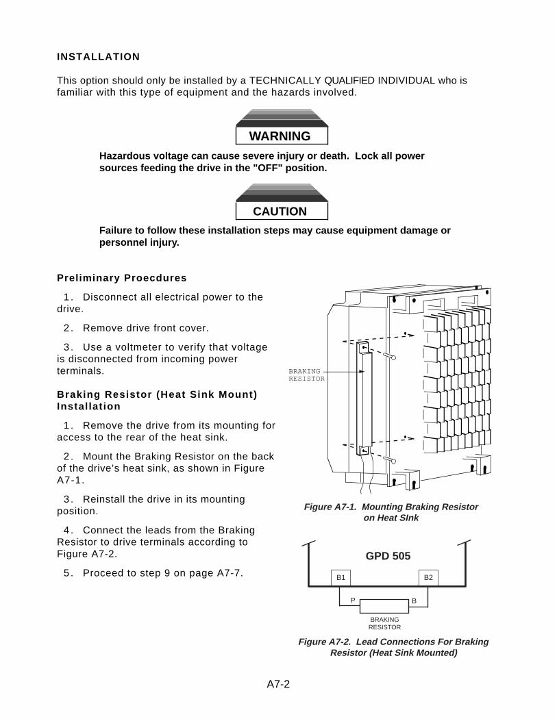
INSTALLATION
This option should only be installed by a TECHNICALLY QUALIFIED INDIVIDUAL who isfamiliar with this type of equipment and the hazards involved.
WARNINGHazardous voltage can cause severe injury or death. Lock all powersources feeding the drive in the "OFF" position.
CAUTION
Failure to follow these installation steps may cause equipment damage orpersonnel injury.
Preliminary Proecdures
1 . Disconnect all electrical power to thedrive.
2 . Remove drive front cover.
3 . Use a voltmeter to verify that voltageis disconnected from incoming powerterminals.
Braking Resistor (Heat Sink Mount)Installation
1 . Remove the drive from its mounting foraccess to the rear of the heat sink.
2 . Mount the Braking Resistor on the backof the drive’s heat sink, as shown in FigureA7-1.
3 . Reinstall the drive in its mountingposition.
4 . Connect the leads from the BrakingResistor to drive terminals according toFigure A7-2.
5 . Proceed to step 9 on page A7-7.
A7-2
Figure A7-1. Mounting Braking Resistoron Heat SInk
BRAKINGRESISTOR
Figure A7-2. Lead Connections For BrakingResistor (Heat Sink Mounted)
B1 B2
BRAKINGRESISTOR
P B
GPD 505
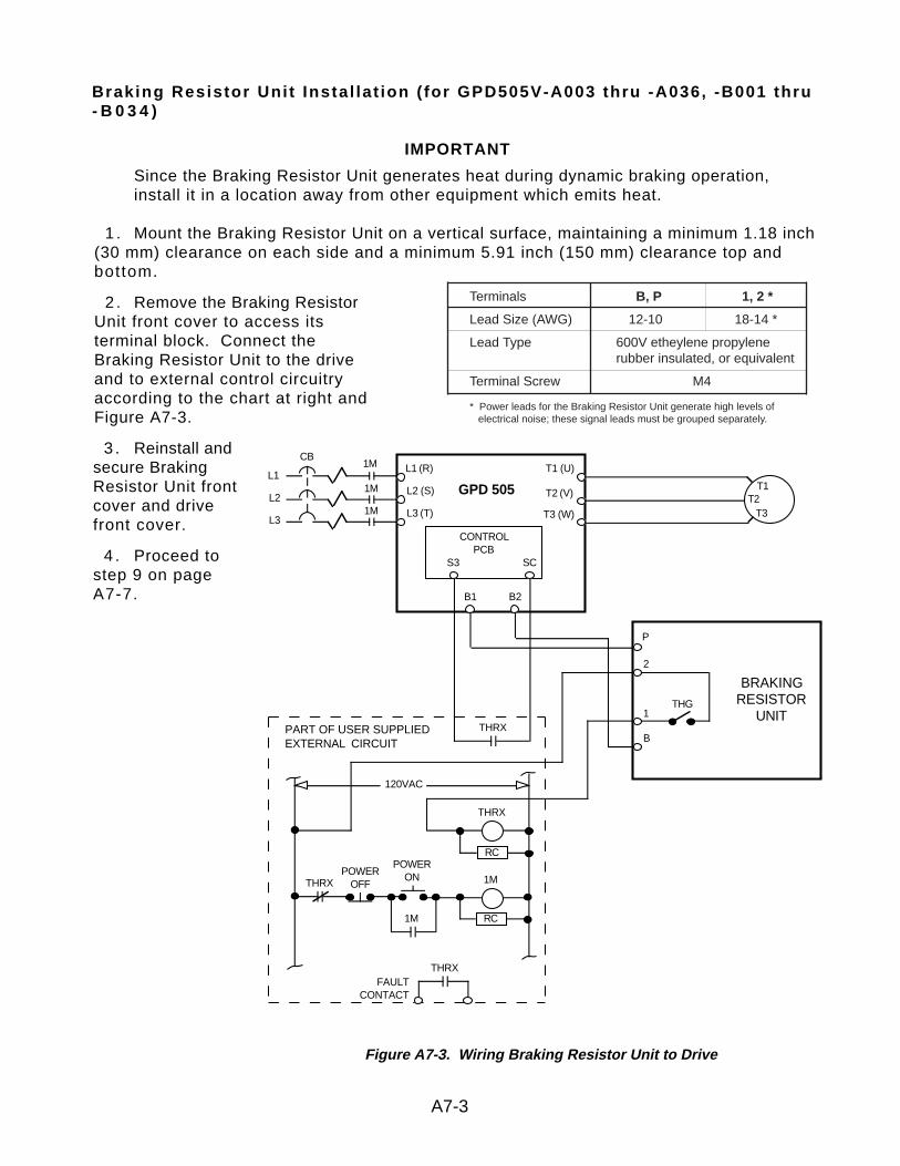
Braking Resistor Unit Instal lat ion ( for GPD505V-A003 thru -A036, -B001 thru- B 0 3 4 )
IMPORTANT
Since the Braking Resistor Unit generates heat during dynamic braking operation, install it in a location away from other equipment which emits heat.
1 . Mount the Braking Resistor Unit on a vertical surface, maintaining a minimum 1.18 inch(30 mm) clearance on each side and a minimum 5.91 inch (150 mm) clearance top andbottom.
2 . Remove the Braking ResistorUnit front cover to access itsterminal block. Connect theBraking Resistor Unit to the driveand to external control circuitryaccording to the chart at right andFigure A7-3.
3 . Reinstall andsecure BrakingResistor Unit frontcover and drivefront cover.
4 . Proceed tostep 9 on pageA7-7.
A7-3
Figure A7-3. Wiring Braking Resistor Unit to Drive
T1T2
T3
L1 (R)
L2 (S)
L3 (T)
T1 (U)
T2 (V)
T3 (W)
GPD 505
CONTROLPCB
S3 SC
PART OF USER SUPPLIEDEXTERNAL CIRCUIT
BRAKINGRESISTOR
UNIT
B
P
2
1THG
THRX
1M
1M
1M
CB
L1
L2
L3
120VAC
THRXFAULT
CONTACT
THRX
RC
1M
RC1M
THRX
POWERONPOWER
OFF
B1 B2
Terminals B, P 1, 2 *
Lead Size (AWG) 12-10 18-14 *
Lead Type 600V etheylene propylenerubber insulated, or equivalent
Terminal Screw M4
* Power leads for the Braking Resistor Unit generate high levels ofelectrical noise; these signal leads must be grouped separately.
Braking Unit(s) and Braking Resistor Unit(s) Instal lat ion (for GPD505V-A054t h r u - A 0 6 8 , - B 3 8 0 t h r u - B 6 7 5 )
IMPORTANT
Since the Braking Resistor Unit generates heat during dynamic braking operation, install it in a location away from other equipment which emits heat.
Select mounting locations for the Braking Unit(s) and Braking Resistor Unit(s) so that wiringbetween the drive and the (Master) Braking Unit, and between each Braking Unit and itsassociated Braking Resistor Unit, is less than 33 feet (10 m).
1 . Mount the Braking Unit(s) and Braking Resistor Unit(s) on vertical surfaces. A BrakingUnit requires a minimum 1.18 inch (30 mm) clearance on each side and a minimum 3.94inch (100 mm) clearance top and bottom; a Braking Resistor Unit requires a minimum 1.97inch (50 mm) clearance in back (i.e. use mounting spacers) and a minimum 7.87 inch (200mm) clearance in front.
2 . Remove DB units’ front covers to access their terminals.
3 . For 380/460V drives only: In each Braking Unit, set the PCB nominal line voltagejumper plug to the correct setting for the installation; this is factory set at the "460V"position.
4 . If multiple Braking Units are being installed, the unit closest to the drive should havethe SLAVE/MASTER jumper on its PCB set to the "MASTER" position (factory setting); allothers must have this jumper moved to the "SLAVE" position.
5 . If a single Braking Unit and Braking Resistor Unit are being installed, connect them to the drive and external control circuitry according to the chart below and Figure A7-4.
If two or more Braking Units and Braking Resistor Units are being installed, connect them to the drive and to external circuitry according to the chart below and Figure A7-5.
A7-4
LEAD SIZE LEAD TERMINALUNIT TERMINALS (AWG) TYPE SCREWS
Braking Resistor Unit B, P 12-10 600V ethylene propylene M51, 2 * 18-14 * rubber insulated or equivalent M4
Braking Unit P, Po, N, B 12-10 600V etheylene propylene M41, 2 * 18-14 * rubber insulated, or equivalent
* Power leads for the Braking Resistor Unit generate high levels ofelectrical noise; these signal leads must be grouped separately.
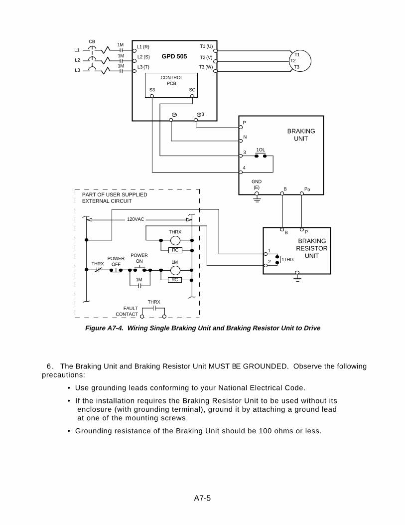
6 . The Braking Unit and Braking Resistor Unit MUST BE GROUNDED. Observe the followingprecautions:
• Use grounding leads conforming to your National Electrical Code.
• If the installation requires the Braking Resistor Unit to be used without its enclosure (with grounding terminal), ground it by attaching a ground lead at one of the mounting screws.
• Grounding resistance of the Braking Unit should be 100 ohms or less.
A7-5
Figure A7-4. Wiring Single Braking Unit and Braking Resistor Unit to Drive
T1T2
T3
L1 (R)
L2 (S)
L3 (T)
T1 (U)
T2 (V)
T3 (W)
GPD 505
CONTROLPCB
S3 SC
PART OF USER SUPPLIEDEXTERNAL CIRCUIT
BRAKINGUNIT
B
P
N
3 1OL
1M
1M
1M
CB
L1
L2
L3
120VAC
THRXFAULT
CONTACT
THRX
RC
1M
RC1M
THRX
POWERONPOWER
OFF
BRAKINGRESISTOR
UNIT1
2 1THG
B
P
P
o
GND(E)
4
+ 3–
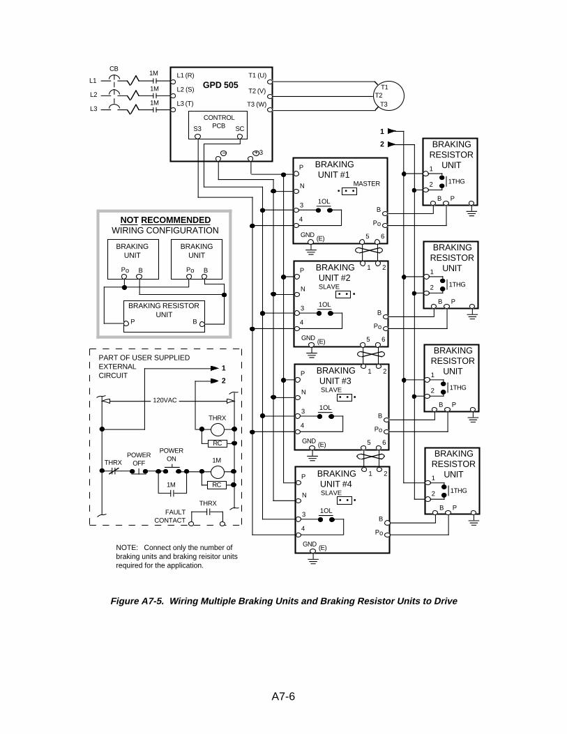
A7-6
Figure A7-5. Wiring Multiple Braking Units and Braking Resistor Units to Drive
T1T2
T3
L1 (R)
L2 (S)
L3 (T)
T1 (U)
T2 (V)
T3 (W)
GPD 505
CONTROLPCBS3 SC
PART OF USER SUPPLIEDEXTERNALCIRCUIT
BRAKINGUNIT #1
B
P
N
3 1OL
1M
1M
1M
CB
L1
L2
L3
120VAC
THRXFAULT
CONTACT
THRX
RC
1M
RC1M
THRX
POWERONPOWER
OFF
BRAKINGRESISTOR
UNIT1
2 1THG
B
P
P
o
(E)
4
1
2
NOTE: Connect only the number ofbraking units and braking reisitor unitsrequired for the application.
GND
• • •MASTER
5 6
BRAKINGUNIT #2
B
P
N
3 1OL
BRAKINGRESISTOR
UNIT1
2 1THG
B
P
P
o
(E)
4
GND
• • •SLAVE
5 6
BRAKINGUNIT #3
B
P
N
3 1OL
BRAKINGRESISTOR
UNIT1
2 1THG
B
P
P
o
(E)
4
GND
• • •SLAVE
5 6
BRAKINGUNIT #4
B
P
N
3 1OL
BRAKINGRESISTOR
UNIT1
2 1THG
B
P
P
o
(E)
4
GND
• • •SLAVE
1 2
1 2
1 2
BRAKINGUNIT
BRAKINGUNIT
NOT RECOMMENDEDWIRING CONFIGURATION
BRAKING RESISTORUNIT
Po Po
P
B B
B
1
2+ 3–
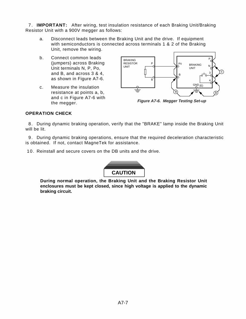
7 . IMPORTANT: After wiring, test insulation resistance of each Braking Unit/BrakingResistor Unit with a 900V megger as follows:
a. Disconnect leads between the Braking Unit and the drive. If equipment with semiconductors is connected across terminals 1 & 2 of the Braking Unit, remove the wiring.
b. Connect common leads (jumpers) across Braking Unit terminals N, P, Po, and B, and across 3 & 4, as shown in Figure A7-6.
c. Measure the insulation resistance at points a, b, and c in Figure A7-6 with the megger.
OPERATION CHECK
8 . During dynamic braking operation, verify that the "BRAKE" lamp inside the Braking Unitwill be lit.
9 . During dynamic braking operations, ensure that the required deceleration characteristicis obtained. If not, contact MagneTek for assistance.
10 . Reinstall and secure covers on the DB units and the drive.
CAUTION
During normal operation, the Braking Unit and the Braking Resistor Unitenclosures must be kept closed, since high voltage is applied to the dynamicbraking circuit.
A7-7
BRAKINGRESISTORUNIT
BRAKINGUNIT
P
B
N
3
4
P
B
P0
GND (E)
c
ba
Figure A7-6. Megger Testing Set-up
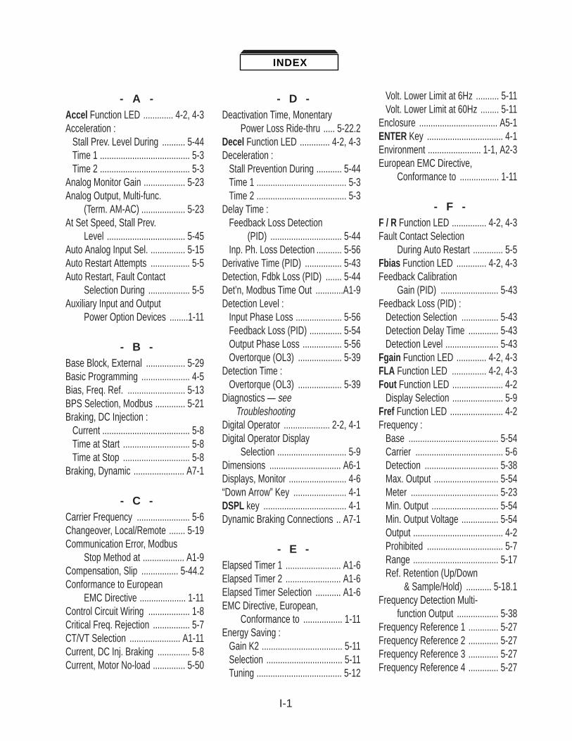
I-1
- A -Accel Function LED ............. 4-2, 4-3Acceleration :
Stall Prev. Level During .......... 5-44Time 1 ....................................... 5-3Time 2 ....................................... 5-3
Analog Monitor Gain .................. 5-23Analog Output, Multi-func.
(Term. AM-AC) ................... 5-23At Set Speed, Stall Prev.
Level .................................. 5-45Auto Analog Input Sel. ............... 5-15Auto Restart Attempts ................. 5-5Auto Restart, Fault Contact
Selection During .................. 5-5Auxiliary Input and Output
Power Option Devices ........1-11
- B -Base Block, External ................. 5-29Basic Programming ..................... 4-5Bias, Freq. Ref. ......................... 5-13BPS Selection, Modbus ............. 5-21Braking, DC Injection :
Current ...................................... 5-8Time at Start ............................. 5-8Time at Stop ............................. 5-8
Braking, Dynamic ...................... A7-1
- C -Carrier Frequency ....................... 5-6Changeover, Local/Remote ....... 5-19Communication Error, Modbus
Stop Method at .................. A1-9Compensation, Slip ................ 5-44.2Conformance to European
EMC Directive .................... 1-11Control Circuit Wiring .................. 1-8Critical Freq. Rejection ................ 5-7CT/VT Selection ...................... A1-11Current, DC Inj. Braking .............. 5-8Current, Motor No-load .............. 5-50
- D -Deactivation Time, Monentary
Power Loss Ride-thru ..... 5-22.2Decel Function LED ............. 4-2, 4-3Deceleration :
Stall Prevention During ........... 5-44Time 1 ....................................... 5-3Time 2 ....................................... 5-3
Delay Time : Feedback Loss Detection
(PID) ............................... 5-44Inp. Ph. Loss Detection ........... 5-56
Derivative Time (PID) ................ 5-43Detection, Fdbk Loss (PID) ....... 5-44Det’n, Modbus Time Out ............A1-9Detection Level :
Input Phase Loss .................... 5-56Feedback Loss (PID) .............. 5-54Output Phase Loss ................. 5-56Overtorque (OL3) ................... 5-39
Detection Time : Overtorque (OL3) ................... 5-39
Diagnostics — seeTroubleshooting
Digital Operator .................... 2-2, 4-1Digital Operator Display
Selection .............................. 5-9Dimensions ............................... A6-1Displays, Monitor ......................... 4-6“Down Arrow” Key ....................... 4-1DSPL key .................................... 4-1Dynamic Braking Connections .. A7-1
- E -Elapsed Timer 1 ........................ A1-6Elapsed Timer 2 ........................ A1-6Elapsed Timer Selection ........... A1-6EMC Directive, European,
Conformance to ................. 1-11Energy Saving :
Gain K2 ................................... 5-11Selection ................................. 5-11Tuning ..................................... 5-12
Volt. Lower Limit at 6Hz .......... 5-11Volt. Lower Limit at 60Hz ........ 5-11
Enclosure .................................. A5-1ENTER Key ................................. 4-1Environment ....................... 1-1, A2-3European EMC Directive,
Conformance to ................. 1-11
- F -F / R Function LED ............... 4-2, 4-3Fault Contact Selection
During Auto Restart ............. 5-5Fbias Function LED ............. 4-2, 4-3Feedback Calibration
Gain (PID) ......................... 5-43Feedback Loss (PID) :
Detection Selection ................ 5-43Detection Delay Time ............. 5-43Detection Level ....................... 5-43
Fgain Function LED ............. 4-2, 4-3FLA Function LED ............... 4-2, 4-3Fout Function LED ...................... 4-2
Display Selection ...................... 5-9Fref Function LED ....................... 4-2Frequency :
Base ....................................... 5-54Carrier ...................................... 5-6Detection ................................ 5-38Max. Output ............................ 5-54Meter ...................................... 5-23Min. Output ............................. 5-54Min. Output Voltage ................ 5-54Output ....................................... 4-2Prohibited ................................. 5-7Range ..................................... 5-17Ref. Retention (Up/Down
& Sample/Hold) ........... 5-18.1Frequency Detection Multi-
function Output .................. 5-38Frequency Reference 1 ............. 5-27Frequency Reference 2 ............. 5-27Frequency Reference 3 ............. 5-27Frequency Reference 4 ............. 5-27
INDEX
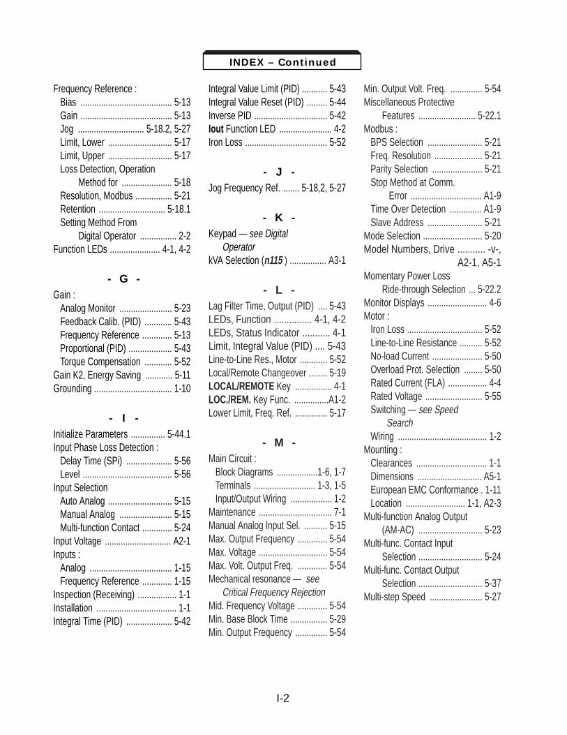
I-2
Frequency Reference : Bias ........................................ 5-13Gain ........................................ 5-13Jog ............................. 5-18.2, 5-27Limit, Lower ............................ 5-17Limit, Upper ............................ 5-17Loss Detection, Operation
Method for ...................... 5-18Resolution, Modbus ................ 5-21Retention ............................. 5-18.1Setting Method From
Digital Operator ................ 2-2Function LEDs ...................... 4-1, 4-2
- G -Gain :
Analog Monitor ....................... 5-23Feedback Calib. (PID) ............ 5-43Frequency Reference ............. 5-13Proportional (PID) ................... 5-43Torque Compensation ............ 5-52
Gain K2, Energy Saving ............ 5-11Grounding .................................. 1-10
- I -Initialize Parameters ............... 5-44.1Input Phase Loss Detection :
Delay Time (SPi) .................... 5-56Level ....................................... 5-56
Input SelectionAuto Analog ............................ 5-15Manual Analog ....................... 5-15Multi-function Contact ............. 5-24
Input Voltage ............................. A2-1Inputs :
Analog .................................... 1-15Frequency Reference ............. 1-15
Inspection (Receiving) ................. 1-1Installation ................................... 1-1Integral Time (PID) .................... 5-42
Integral Value Limit (PID) ........... 5-43Integral Value Reset (PID) ......... 5-44Inverse PID ................................ 5-42Iout Function LED ....................... 4-2Iron Loss .................................... 5-52
- J -Jog Frequency Ref. ....... 5-18,2, 5-27
- K -Keypad — see Digital
OperatorkVA Selection (n115 ) ................ A3-1
- L -Lag Filter Time, Output (PID) .... 5-43LEDs, Function ............... 4-1, 4-2LEDs, Status Indicator ........... 4-1Limit, Integral Value (PID) .... 5-43Line-to-Line Res., Motor ............ 5-52Local/Remote Changeover ........ 5-19LOCAL/REMOTE Key ................ 4-1LOC./REM. Key Func. ...............A1-2Lower Limit, Freq. Ref. .............. 5-17
- M -Main Circuit :
Block Diagrams ..................1-6, 1-7Terminals ........................... 1-3, 1-5Input/Output Wiring .................. 1-2
Maintenance ................................ 7-1Manual Analog Input Sel. .......... 5-15Max. Output Frequency ............. 5-54Max. Voltage .............................. 5-54Max. Volt. Output Freq. ............. 5-54Mechanical resonance — see
Critical Frequency RejectionMid. Frequency Voltage ............. 5-54Min. Base Block Time ................ 5-29Min. Output Frequency .............. 5-54
Min. Output Volt. Freq. .............. 5-54Miscellaneous Protective
Features ......................... 5-22.1Modbus :
BPS Selection ........................ 5-21Freq. Resolution ..................... 5-21Parity Selection ...................... 5-21Stop Method at Comm.
Error ............................... A1-9Time Over Detection .............. A1-9Slave Address ........................ 5-21
Mode Selection .......................... 5-20Model Numbers, Drive ........... -v-,
A2-1, A5-1Momentary Power Loss
Ride-through Selection ... 5-22.2Monitor Displays .......................... 4-6Motor :
Iron Loss ................................. 5-52Line-to-Line Resistance .......... 5-52No-load Current ...................... 5-50Overload Prot. Selection ........ 5-50Rated Current (FLA) ................. 4-4Rated Voltage ......................... 5-55Switching — see Speed
SearchWiring ....................................... 1-2
Mounting : Clearances ............................... 1-1Dimensions ............................ A5-1European EMC Conformance . 1-11Location .......................... 1-1, A2-3
Multi-function Analog Output(AM-AC) ............................ 5-23
Multi-func. Contact InputSelection ............................ 5-24
Multi-func. Contact OutputSelection ............................ 5-37
Multi-step Speed ....................... 5-27
INDEX – Continued

I-3
- N -Nameplate, Motor ...................... 5-50No-load Motor Current ............... 5-50
- O -Off-delay Timer .......................... 5-32Offset (PID) ................................ 5-43OH1 Stopping Method
Selection ........................... A1-4On-delay Timer .......................... 5-32Operation Method for Freq.
Ref. Loss Detection ........... 5-18Operation Mode Selection ........ 5-26,
5-42Operator Display ......................... 4-1Options — see Peripheral
DevicesOutput, Analog, Multi-func. ........ 5-23Output Frequency :
Max. ........................................ 5-54Max. Voltage ........................... 5-54Min. ......................................... 5-54
Output Lag Filter Time (PID) ..... 5-43Output, Multi-func., Freq.
Detection ........................... 5-38Output Phase Loss Detection :
Delay Time ............................. 5-56Level ....................................... 5-56
Output Selection, Multi-Func.Contact .............................. 5-37
OutputsAnalog .................................... 5-23Contact ................................... 5-37
Overload Prot. Selection,Motor ................................. 5-50
Overtorque Detection (OL3) : Function Selection .................. 5-39Level ....................................... 5-39Time ........................................ 5-39
- P -Parameters
Factory Reset (Initialize) ......... 5-43List ......................................... A1-1Programming ............................ 4-5
Parity Selection, Modbus ........... 5-21Peripheral Devices :
AC reactor ............................... 1-11Molded-case circuit
breaker (MCCB) ......... 1-11, A2-1Noise filter ............................... 1-11
PID Control ................................ 5-41PID Disable (Input) ..................... 5-44PID, Inverse ............................... 5-42PID Selection ............................. 5-41PID Settings .............................. 5-43Potentiometer ............................... -ii-Power Loss Ride-thru Time ....... 5-22Power Rotation ......................... A1-1Power Supply ..................... 1-2, A2-1Preset speeds — see
Multi-step SpeedsPRGM Function LED ............ 4-1, 4-4Prohibited Frequency 1 ............... 5-7Prohibited Frequency 2 ............... 5-7Proh. Frequency Range .............. 5-7Proportional Gain (PID) ............. 5-42Protection :
Overcurrent .............................. 6-1Overheat ................................... 6-1Overtemperature ...................... 6-1Overtorque ............................. 5-39Overvoltage .............................. 6-1Thermal Overload ................... 5-50Undervoltage ........................... 6-1
Protective Functions, Miscellaneous ................. 5-22.1
PWM Frequency — seeCarrier Frequency
- R -Range, Prohibited Freq. .............. 5-7Rated Current, Motor ......... 4-4, 5-50Ratings ................................ -v-, A2-1Receiving ..................................... 1-1Reduction Level During
Speed Search, V/f ............. 5-30Reset Codes: 2-Wire, 3-Wire
Initialization ..................... 5-44.1RESET Key — see
STOP/RESET KeyResistance, Motor Line-to-
Line .................................... 5-52Reverse Run Prohibit ................ A1-2Ride-thru Method, Momen-
tary Power Loss .............. 5-22.2Ride-thru Time, Power Loss ... 5-22.2Rotation Direction ..................... A1-1RUN Key ..................................... 4-1Running :
Forward ................................... 2-3Reverse ................................... 2-3
- S -Sample/Hold Function ................5-33
Freq. Ref. Retention for ......... 5-18S-Curve Selection ....................... 5-4Shock Resistance –– see
S-CurveSkip Frequency –– see
Prohibited FrequencySlave Address, Modbus ............ 5-21Slip Compemsation ................ 5-44.2Soft Start — see S-CurveSpare Parts ............................... A5-1Specifications ............................ A2-1Speed :
Agree ...................................... 5-38Range .................................... A2-1Search .................................... 5-30
INDEX – Continued
I-4
Speed Search Level .................. 5-30Stall Prevention :
During Decel ........................... 5-46Level At Set Speed ................. 5-47Level During Accel ................. 5-46
Start-up, Initial ............................. 2-1Start-up Procedure,
Simplified ............................... -i-Step Voltage, Tuning at
100% Output Voltage (Energy Saving) ................. 5-11
Step Voltage, Tuning at5% Output Voltage(Energy Saving) ................. 5-11
Stop Method at Comm.Error, Modbus ................... A1-9
Stop Method Sel. (OH1) ............ A1-4Stopping :
Fast Stop ................................ 5-25Stopping Method ....................... 5-48STOP/RESET Key ....................... 4-1Switching Frequency — see
Carrier Frequency
- T -Temperature :
Ambient ........................... 1-1, A2-3Storage .................................. A2-3
Terminals : Description ................. 1-3, 1-5, 1-9Functions ........................... 1-5, 1-9Screw Sizes .............................. 1-3
Thermal Overload Protection .... 5-50Time of Average kW
(Energy Saving) ................ A1-9Time Over Detection,
Modbus ............................. A1-9Torque :
Compensation Gain ................ 5-52Detection ................................ 5-39V/f Pattern Setting .................. 5-53
Troubleshooting ........................... 7-1Tuning, Energy Saving .............. 5-12
- U -U-xx Parameters (Monitor
Displays) .............................. 4-6Up/Down Function, Freq.
Ref. Retention for .............. 5-18Upper Limit, Freq. Ref. .............. 5-17"Up Arrow" Key ............................ 4-1
- V -V/f During Speed Search ........... 5-31V / F Function LED ............... 4-2, 4-3V/f Pattern Selection .................. 5-52Voltage :
Input .............................. 5-54, A2-1Max. ........................................ 5-54Mid. Frequency ....................... 5-54Motor Rated ............................ 5-55
Voltage Limit of Tuning (Energy Saving) ................. 5-12
Voltage Lower Limit at 6Hz(Energy Saving) ................. 5-12
Voltage Lower Limit at 60Hz(Energy Saving) ................. 5-12
- W -Weight ....................................... A5-1Wiring :
3-Wire Control ................. 1-8, 1-16Control Circuit ........................... 1-8Diagrams ....................... 1-15, 1-17Distances .......................... 1-2, 1-8Main Circuit Input/Output .......... 1-2
INDEX – Continued

Please send information on the following:
WinDDM (DriveDataManager For Windows)A program to create and edit configuration files for MagneTek AC drives,and to upload/download configuration files for high-speed programming, production change, or backup.
GPD 505 Programming Reference GuideFree pocket-size booklet which provides the user a rapid reference for programming GPD 505 parameters. Allow one week for delivery.
Additional Copies of GPD 505 Technical ManualInformation will be provided on how to order copies of TM 4505.
Name ___________________________________________________
Position/Title ______________________________________________
Company ___________________________________________________
Address ___________________________________________________
City _____________________________ State _____ ZIP ___________
Telephone ( ) ____________________
GPD 505 : Model No. _____________
Application : __________________________________________
__________________________________________
Purchased through (if known) : __________________________________
Mail this form , or FAX ( 414 ) 782-3418

Data subject to change without notice. GPD, and Century are trademarks of MagneTek, Inc. Modbus Plus and ModConnect are trademarks of Modicon, Inc.
MagneTek Drives and Systems16555 West Ryerson RoadNew Berlin, WI 53151(800) 541-0939, (414) 782-0200, FAX (414) 782-3418
TM 4505 © 1996 MagneTek, Inc. 7/97
MagneTek
GPD 505