Embed Size (px)
Citation preview
8/10/2019 GLR-SGR-E (2)
http://slidepdf.com/reader/full/glr-sgr-e-2 1/2
Völkel Mikroelektronik GmbH Otto-Hahn-Straße 30 D-48161 Münster Tel. 02534-9731-0 Fax 02534-973110 www.voelkel.de
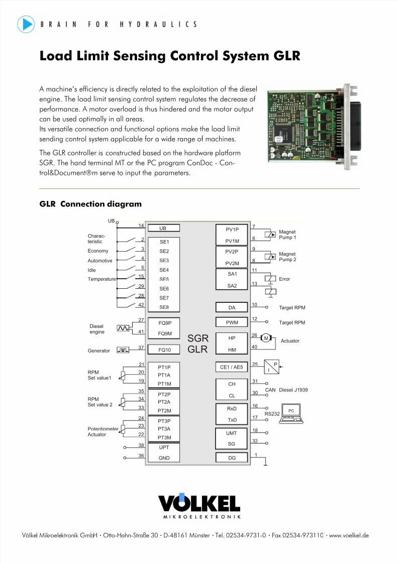
Load Limit Sensing Control System GLR
A machine’s efficiency is directly related to the exploitation of the diesel
engine. The load limit sensing control system regulates the decrease ofperformance. A motor overload is thus hindered and the motor outputcan be used optimally in all areas.Its versatile connection and functional options make the load limitsending control system applicable for a wide range of machines.
The GLR controller is constructed based on the hardware platformSGR. The hand terminal MT or the PC program ConDoc - Con-trol&Document®m serve to input the parameters.
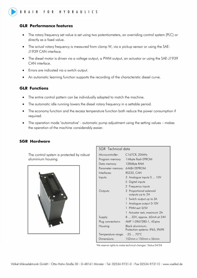
GLR Connection diagram
PT1P21
20
19PT1M
SE12
SE23
SE34
SE45
SE515
SE629
SE728
SE842
PV1P
PV1M
7
6
PI
25
DG
UB14
1
PT2P35
34
33PT2A
PT2M
UPT38
37
36 GND
CH
CL
31
30
SGRGLR
PV2P
PV2M
9
8
SA1
SA2
11
13
DA 10
12FQ9P
PT3P24
23
22PT3A
PT3M
UB
CAN
RS232
27
41
PC
HP
HM
26
40
M
RxD
UMT
SG
16
17
18
32
PT1A
TxD
CE1 / AE5
FQ10
PWM
FQ9MDieselengine
Generator
Charac-teristic
Economy
Automotive
Idle
Temperature
RPMSet value1
RPMSet value 2
Potentiometer Actuator
MagnetPump 1
MagnetPump 2
Error
Target RPM
Target RPM
Actuator
Diesel J1939
8/10/2019 GLR-SGR-E (2)
http://slidepdf.com/reader/full/glr-sgr-e-2 2/2
Völkel Mikroelektronik GmbH Otto-Hahn-Straße 30 D-48161 Münster Tel. 02534-9731-0 Fax 02534-973110 www.voelkel.de
GLR Performance features
• The rotary frequency set value is set using two potentiometers, an overriding control system (PLC) ordirectly as a fixed value.
• The actual rotary frequency is measured from clamp W, via a pickup sensor or using the SAE-J1939 CAN interface.
• The diesel motor is driven via a voltage output, a PWM output, an actuator or using the SAE-J1939CAN interface.
• Errors are indicated via a switch output.
• An automatic learning function supports the recording of the characteristic diesel curve.
GLR Functions
• The entire control pattern can be individually adapted to match the machine.• The automatic idle running lowers the diesel rotary frequency in a settable period.
• The economy function and the excess temperature function both reduce the power consumption ifrequired.
• The operation mode "automotive" - automatic pump adjustment using the setting values – makesthe operation of the machine considerably easier.
SGR Hardware
The control system is protected by robustaluminium housing.
SGR Technical dataMicrocontroller: C167CR, 20 MHzProgram memory: 1 Mbyte flash EPROMData memory: 128 kByte RAMParameter memory: 64 kBit EEPROMInterfaces: RS232, CANInputs: 3 Analogue inputs 0 ... 10 V
5 Digital inputs2 Frequency inputs
Outputs: 2 Proportional solenoid
outputs up to 2 A1 Switch output up to 3A1 Analogue output 0-10V1 PWM exit 0/5V1 Actuator exit, maximum 2A
Supply: 8 ... 32 V, approx. 60 mA at 24VPlug connections: AMP 1-0967280-1, 42-pinsHousing: Black aluminium,
Protection systems: IP65, IP69KTemperature range: -25 ... 70 ° CDimensions: 152 mm x 150 mm x 56 mm
We reserve rights to make technical changes Status 04/04

![Welcome []...• Welcome & Introductions • GLR Inc. Update • GLR Economic Development Update • GLR Workforce Development Update • GLR Communications Update • Wrap-Up 1,414](https://img.pdfslide.us/doc/110x75/5ed221c2821d0855e2414db8/welcome-a-welcome-introductions-a-glr-inc-update-a-glr-economic.jpg)