Embed Size (px)
Citation preview
PRODUCT SERIES1200 & 7200
GLOBE/ANGLECAGE-GUIDEDCONTROL VALVES
kentintrol

KOSO KENT INTROLSUPPLIES A DIVERSERANGE OF PRECISION-MANUFACTUREDCONTROL, CHOKE,AND ROTARY VALVESFOR OIL AND GAS,PETROCHEMICAL ANDPOWER INDUSTRIES–WORLDWIDE
PRODUCT SERIES1200 & 7200
TABLE OF CONTENTS
– TRIM OPTIONS 04– LIQUID SERVICE TRIM SELECTION 05– VECTOR SEVERE SERVICE TRIMS 09– SELECTION GUIDELINES 10
01
CAGE-GUIDED VALVES
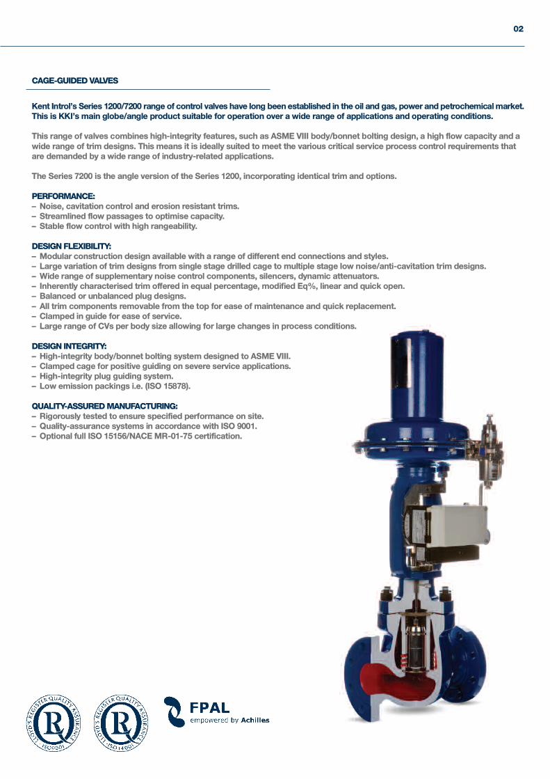
Kent Introl’s Series 1200/7200 range of control valves have long been established in the oil and gas, power and petrochemical market.This is KKI’s main globe/angle product suitable for operation over a wide range of applications and operating conditions.
This range of valves combines high-integrity features, such as ASME VIII body/bonnet bolting design, a high flow capacity and awide range of trim designs. This means it is ideally suited to meet the various critical service process control requirements thatare demanded by a wide range of industry-related applications.
The Series 7200 is the angle version of the Series 1200, incorporating identical trim and options.
PERFORMANCE:– Noise, cavitation control and erosion resistant trims.– Streamlined flow passages to optimise capacity.– Stable flow control with high rangeability.
DESIGN FLEXIBILITY:– Modular construction design available with a range of different end connections and styles.– Large variation of trim designs from single stage drilled cage to multiple stage low noise/anti-cavitation trim designs.– Wide range of supplementary noise control components, silencers, dynamic attenuators.– Inherently characterised trim offered in equal percentage, modified Eq%, linear and quick open.– Balanced or unbalanced plug designs.– All trim components removable from the top for ease of maintenance and quick replacement.– Clamped in guide for ease of service.– Large range of CVs per body size allowing for large changes in process conditions.
DESIGN INTEGRITY:– High-integrity body/bonnet bolting system designed to ASME VIII.– Clamped cage for positive guiding on severe service applications.– High-integrity plug guiding system.– Low emission packings i.e. (ISO 15878).
QUALITY-ASSURED MANUFACTURING:– Rigorously tested to ensure specified performance on site.– Quality-assurance systems in accordance with ISO 9001.– Optional full ISO 15156/NACE MR-01-75 certification.
02
PRODUCT SERIES1200 & 7200
03
SCOPE OF DESIGN
VALVE BODY/END CONNECTION SIZES– 1” to 36” (25mm to 900mm) nominal bore.
VALVE BODY RATINGS– ANSI 150 to ANSI 4500 (PN10 to PN640).– API ratings can also be supplied.
DESIGN STANDARDS– ASME B16.34.– ASME VIII.– ASME FCI 70-2 control valve seat.
LEAKAGE– ASME B16.25 – butt weld end valves– ASME B16.5 – pipe flanges and flange fittings– NACE MR-01-75/ ISO 15156– Designs fully PED certified.
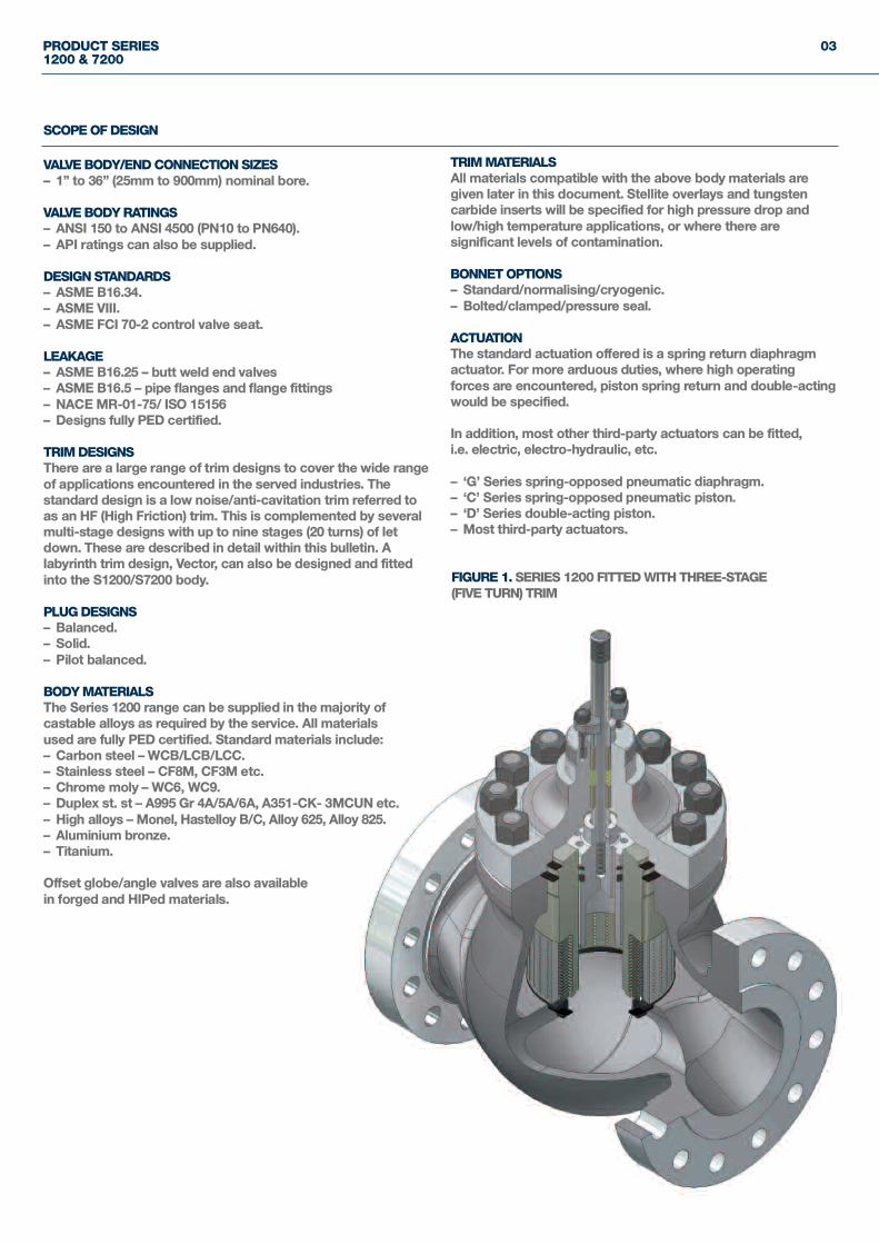
TRIM DESIGNSThere are a large range of trim designs to cover the wide rangeof applications encountered in the served industries. Thestandard design is a low noise/anti-cavitation trim referred toas an HF (High Friction) trim. This is complemented by severalmulti-stage designs with up to nine stages (20 turns) of letdown. These are described in detail within this bulletin. Alabyrinth trim design, Vector, can also be designed and fittedinto the S1200/S7200 body.
PLUG DESIGNS– Balanced.– Solid.– Pilot balanced.
BODY MATERIALSThe Series 1200 range can be supplied in the majority ofcastable alloys as required by the service. All materialsused are fully PED certified. Standard materials include:– Carbon steel – WCB/LCB/LCC.– Stainless steel – CF8M, CF3M etc.– Chrome moly – WC6, WC9.– Duplex st. st – A995 Gr 4A/5A/6A, A351-CK- 3MCUN etc.– High alloys – Monel, Hastelloy B/C, Alloy 625, Alloy 825.– Aluminium bronze.– Titanium.
Offset globe/angle valves are also availablein forged and HIPed materials.
TRIM MATERIALSAll materials compatible with the above body materials aregiven later in this document. Stellite overlays and tungstencarbide inserts will be specified for high pressure drop andlow/high temperature applications, or where there aresignificant levels of contamination.
BONNET OPTIONS– Standard/normalising/cryogenic.– Bolted/clamped/pressure seal.
ACTUATIONThe standard actuation offered is a spring return diaphragmactuator. For more arduous duties, where high operatingforces are encountered, piston spring return and double-actingwould be specified.
In addition, most other third-party actuators can be fitted,i.e. electric, electro-hydraulic, etc.
– ‘G’ Series spring-opposed pneumatic diaphragm.– ‘C’ Series spring-opposed pneumatic piston.– ‘D’ Series double-acting piston.– Most third-party actuators.
FIGURE 1. SERIES 1200 FITTED WITH THREE-STAGE(FIVE TURN) TRIM
04
GENERAL DESCRIPTION
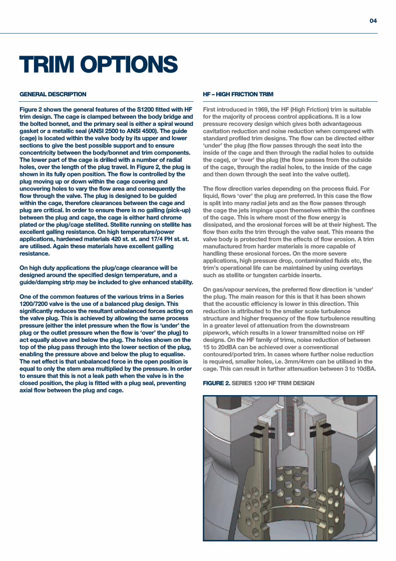
Figure 2 shows the general features of the S1200 fitted with HFtrim design. The cage is clamped between the body bridge andthe bolted bonnet, and the primary seal is either a spiral woundgasket or a metallic seal (ANSI 2500 to ANSI 4500). The guide(cage) is located within the valve body by its upper and lowersections to give the best possible support and to ensureconcentricity between the body/bonnet and trim components.The lower part of the cage is drilled with a number of radialholes, over the length of the plug travel. In Figure 2, the plug isshown in its fully open position. The flow is controlled by theplug moving up or down within the cage covering anduncovering holes to vary the flow area and consequently theflow through the valve. The plug is designed to be guidedwithin the cage, therefore clearances between the cage andplug are critical. In order to ensure there is no galling (pick-up)between the plug and cage, the cage is either hard chromeplated or the plug/cage stellited. Stellite running on stellite hasexcellent galling resistance. On high temperature/powerapplications, hardened materials 420 st. st. and 17/4 PH st. st.are utilised. Again these materials have excellent gallingresistance.
On high duty applications the plug/cage clearance will bedesigned around the specified design temperature, and aguide/damping strip may be included to give enhanced stability.
One of the common features of the various trims in a Series1200/7200 valve is the use of a balanced plug design. Thissignificantly reduces the resultant unbalanced forces acting onthe valve plug. This is achieved by allowing the same processpressure (either the inlet pressure when the flow is ‘under’ theplug or the outlet pressure when the flow is ‘over’ the plug) toact equally above and below the plug. The holes shown on thetop of the plug pass through into the lower section of the plug,enabling the pressure above and below the plug to equalise.The net effect is that unbalanced force in the open position isequal to only the stem area multiplied by the pressure. In orderto ensure that this is not a leak path when the valve is in theclosed position, the plug is fitted with a plug seal, preventingaxial flow between the plug and cage.
HF – HIGH FRICTION TRIM
First introduced in 1969, the HF (High Friction) trim is suitablefor the majority of process control applications. It is a lowpressure recovery design which gives both advantageouscavitation reduction and noise reduction when compared withstandard profiled trim designs. The flow can be directed either‘under’ the plug (the flow passes through the seat into theinside of the cage and then through the radial holes to outsidethe cage), or ‘over’ the plug (the flow passes from the outsideof the cage, through the radial holes, to the inside of the cageand then down through the seat into the valve outlet).
The flow direction varies depending on the process fluid. Forliquid, flows ‘over’ the plug are preferred. In this case the flowis split into many radial jets and as the flow passes throughthe cage the jets impinge upon themselves within the confinesof the cage. This is where most of the flow energy isdissipated, and the erosional forces will be at their highest. Theflow then exits the trim through the valve seat. This means thevalve body is protected from the effects of flow erosion. A trimmanufactured from harder materials is more capable ofhandling these erosional forces. On the more severeapplications, high pressure drop, contaminated fluids etc, thetrim’s operational life can be maintained by using overlayssuch as stellite or tungsten carbide inserts.
On gas/vapour services, the preferred flow direction is ‘under’the plug. The main reason for this is that it has been shownthat the acoustic efficiency is lower in this direction. Thisreduction is attributed to the smaller scale turbulencestructure and higher frequency of the flow turbulence resultingin a greater level of attenuation from the downstreampipework, which results in a lower transmitted noise on HFdesigns. On the HF family of trims, noise reduction of between15 to 20dBA can be achieved over a conventionalcontoured/ported trim. In cases where further noise reductionis required, smaller holes, i.e. 3mm/4mm can be utilised in thecage. This can result in further attenuation between 3 to 10dBA.
FIGURE 2. SERIES 1200 HF TRIM DESIGN
TRIM OPTIONS
PRODUCT SERIES1200 & 7200
05
FOR FLASHING SERVICE/CONTAMINATED SERVICE
Over 30 years of supplying valves into the oil and gas retrieval industry have resultedin KKI gaining a great depth of knowledge in providing solutions for arduous serviceapplications.
There is no hard and fast rule for identifying a severe service application. However, wemay assume the following as potentially severe liquid services:– Pressure drop >50bar (700psi).– Flashing services P2 - Pv >30bar (435psi).– Multi-phase P1 - P2 >30bar.– Contaminated service.
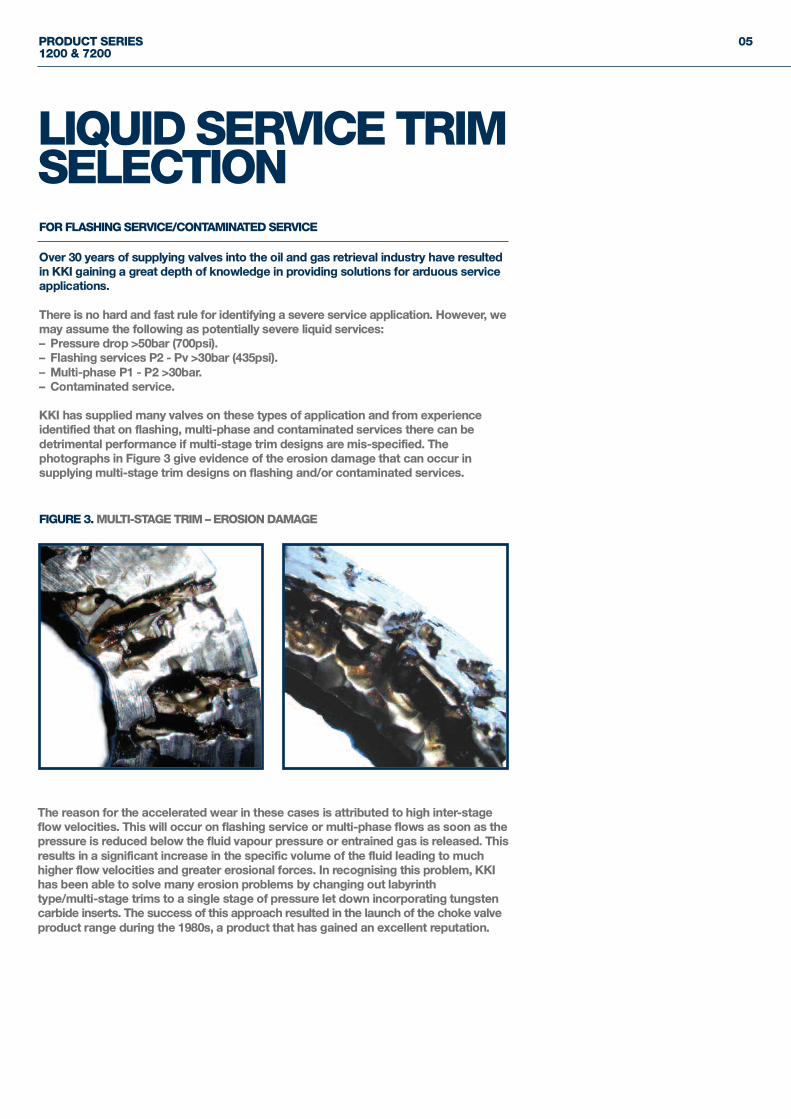
KKI has supplied many valves on these types of application and from experienceidentified that on flashing, multi-phase and contaminated services there can bedetrimental performance if multi-stage trim designs are mis-specified. Thephotographs in Figure 3 give evidence of the erosion damage that can occur insupplying multi-stage trim designs on flashing and/or contaminated services.
FIGURE 3. MULTI-STAGE TRIM – EROSION DAMAGE
LIQUID SERVICE TRIMSELECTION
The reason for the accelerated wear in these cases is attributed to high inter-stageflow velocities. This will occur on flashing service or multi-phase flows as soon as thepressure is reduced below the fluid vapour pressure or entrained gas is released. Thisresults in a significant increase in the specific volume of the fluid leading to muchhigher flow velocities and greater erosional forces. In recognising this problem, KKIhas been able to solve many erosion problems by changing out labyrinthtype/multi-stage trims to a single stage of pressure let down incorporating tungstencarbide inserts. The success of this approach resulted in the launch of the choke valveproduct range during the 1980s, a product that has gained an excellent reputation.
06
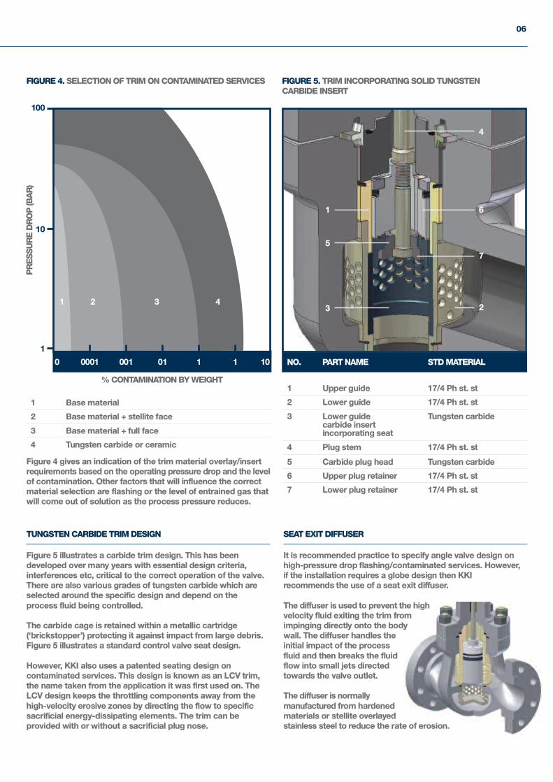
FIGURE 4. SELECTION OF TRIM ON CONTAMINATED SERVICES FIGURE 5. TRIM INCORPORATING SOLID TUNGSTENCARBIDE INSERT
100
10
1
% CONTAMINATION BY WEIGHT
0 0001 001 01 1 1 10
PRESSURE DROP (BAR)
NO. PART NAME STD MATERIAL
1 Upper guide 17/4 Ph st. st
2 Lower guide 17/4 Ph st. st
3 Lower guide Tungsten carbidecarbide insertincorporating seat
4 Plug stem 17/4 Ph st. st
5 Carbide plug head Tungsten carbide
6 Upper plug retainer 17/4 Ph st. st
7 Lower plug retainer 17/4 Ph st. st
1
1 2 3 423
4
5
6
7
1 Base material
2 Base material + stellite face
3 Base material + full face
4 Tungsten carbide or ceramic
TUNGSTEN CARBIDE TRIM DESIGN
Figure 5 illustrates a carbide trim design. This has beendeveloped over many years with essential design criteria,interferences etc, critical to the correct operation of the valve.There are also various grades of tungsten carbide which areselected around the specific design and depend on theprocess fluid being controlled.
The carbide cage is retained within a metallic cartridge(‘brickstopper’) protecting it against impact from large debris.Figure 5 illustrates a standard control valve seat design.
However, KKI also uses a patented seating design oncontaminated services. This design is known as an LCV trim,the name taken from the application it was first used on. TheLCV design keeps the throttling components away from thehigh-velocity erosive zones by directing the flow to specificsacrificial energy-dissipating elements. The trim can beprovided with or without a sacrificial plug nose.
SEAT EXIT DIFFUSER
It is recommended practice to specify angle valve design onhigh-pressure drop flashing/contaminated services. However,if the installation requires a globe design then KKIrecommends the use of a seat exit diffuser.
The diffuser is used to prevent the highvelocity fluid exiting the trim fromimpinging directly onto the bodywall. The diffuser handles theinitial impact of the processfluid and then breaks the fluidflow into small jets directedtowards the valve outlet.
The diffuser is normallymanufactured from hardened materials or stellite overlayedstainless steel to reduce the rate of erosion.
Figure 4 gives an indication of the trim material overlay/insertrequirements based on the operating pressure drop and the levelof contamination. Other factors that will influence the correctmaterial selection are flashing or the level of entrained gas thatwill come out of solution as the process pressure reduces.
PRODUCT SERIES1200 & 7200
07
MULTI-STAGE GUIDES, HFD, HFT & HFL
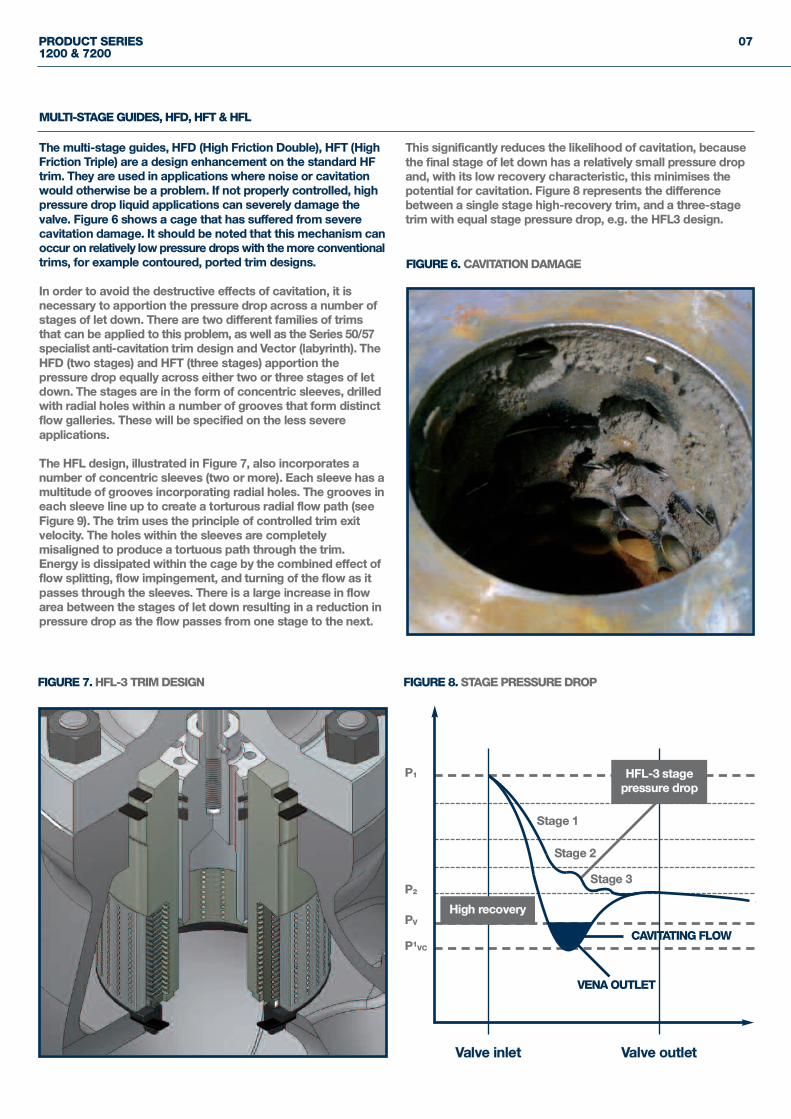
The multi-stage guides, HFD (High Friction Double), HFT (HighFriction Triple) are a design enhancement on the standard HFtrim. They are used in applications where noise or cavitationwould otherwise be a problem. If not properly controlled, highpressure drop liquid applications can severely damage thevalve. Figure 6 shows a cage that has suffered from severecavitation damage. It should be noted that this mechanism canoccur on relatively low pressure drops with the more conventionaltrims, for example contoured, ported trim designs.
In order to avoid the destructive effects of cavitation, it isnecessary to apportion the pressure drop across a number ofstages of let down. There are two different families of trimsthat can be applied to this problem, as well as the Series 50/57specialist anti-cavitation trim design and Vector (labyrinth). TheHFD (two stages) and HFT (three stages) apportion thepressure drop equally across either two or three stages of letdown. The stages are in the form of concentric sleeves, drilledwith radial holes within a number of grooves that form distinctflow galleries. These will be specified on the less severeapplications.
The HFL design, illustrated in Figure 7, also incorporates anumber of concentric sleeves (two or more). Each sleeve has amultitude of grooves incorporating radial holes. The grooves ineach sleeve line up to create a torturous radial flow path (seeFigure 9). The trim uses the principle of controlled trim exitvelocity. The holes within the sleeves are completelymisaligned to produce a tortuous path through the trim.Energy is dissipated within the cage by the combined effect offlow splitting, flow impingement, and turning of the flow as itpasses through the sleeves. There is a large increase in flowarea between the stages of let down resulting in a reduction inpressure drop as the flow passes from one stage to the next.
This significantly reduces the likelihood of cavitation, becausethe final stage of let down has a relatively small pressure dropand, with its low recovery characteristic, this minimises thepotential for cavitation. Figure 8 represents the differencebetween a single stage high-recovery trim, and a three-stagetrim with equal stage pressure drop, e.g. the HFL3 design.
FIGURE 6. CAVITATION DAMAGE
FIGURE 7. HFL-3 TRIM DESIGN
P1
PV
P2
P1VC
Stage 1
Stage 2
Valve inlet Valve outlet
Stage 3
CAVITATING FLOW
FIGURE 8. STAGE PRESSURE DROP
VENA OUTLET
HFL-3 stagepressure drop
High recovery
08
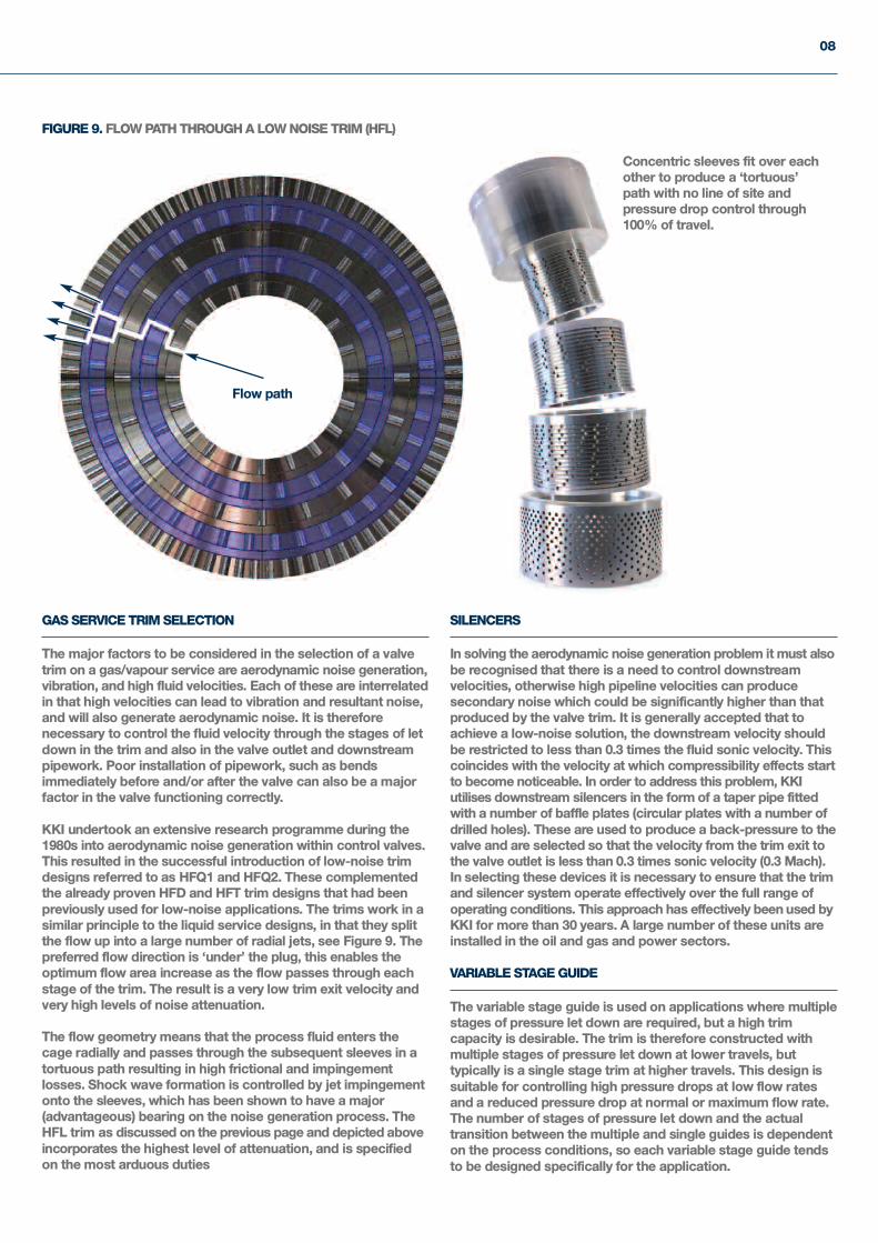
FIGURE 9. FLOW PATH THROUGH A LOW NOISE TRIM (HFL)
Flow path
GAS SERVICE TRIM SELECTION
The major factors to be considered in the selection of a valvetrim on a gas/vapour service are aerodynamic noise generation,vibration, and high fluid velocities. Each of these are interrelatedin that high velocities can lead to vibration and resultant noise,and will also generate aerodynamic noise. It is thereforenecessary to control the fluid velocity through the stages of letdown in the trim and also in the valve outlet and downstreampipework. Poor installation of pipework, such as bendsimmediately before and/or after the valve can also be a majorfactor in the valve functioning correctly.
KKI undertook an extensive research programme during the1980s into aerodynamic noise generation within control valves.This resulted in the successful introduction of low-noise trimdesigns referred to as HFQ1 and HFQ2. These complementedthe already proven HFD and HFT trim designs that had beenpreviously used for low-noise applications. The trims work in asimilar principle to the liquid service designs, in that they splitthe flow up into a large number of radial jets, see Figure 9. Thepreferred flow direction is ‘under’ the plug, this enables theoptimum flow area increase as the flow passes through eachstage of the trim. The result is a very low trim exit velocity andvery high levels of noise attenuation.
The flow geometry means that the process fluid enters thecage radially and passes through the subsequent sleeves in atortuous path resulting in high frictional and impingementlosses. Shock wave formation is controlled by jet impingementonto the sleeves, which has been shown to have a major(advantageous) bearing on the noise generation process. TheHFL trim as discussed on the previous page and depicted aboveincorporates the highest level of attenuation, and is specifiedon the most arduous duties
SILENCERS
In solving the aerodynamic noise generation problem it must alsobe recognised that there is a need to control downstreamvelocities, otherwise high pipeline velocities can producesecondary noise which could be significantly higher than thatproduced by the valve trim. It is generally accepted that toachieve a low-noise solution, the downstream velocity shouldbe restricted to less than 0.3 times the fluid sonic velocity. Thiscoincides with the velocity at which compressibility effects startto become noticeable. In order to address this problem, KKIutilises downstream silencers in the form of a taper pipe fittedwith a number of baffle plates (circular plates with a number ofdrilled holes). These are used to produce a back-pressure to thevalve and are selected so that the velocity from the trim exit tothe valve outlet is less than 0.3 times sonic velocity (0.3 Mach).In selecting these devices it is necessary to ensure that the trimand silencer system operate effectively over the full range ofoperating conditions. This approach has effectively been used byKKI for more than 30 years. A large number of these units areinstalled in the oil and gas and power sectors.
VARIABLE STAGE GUIDE
The variable stage guide is used on applications where multiplestages of pressure let down are required, but a high trimcapacity is desirable. The trim is therefore constructed withmultiple stages of pressure let down at lower travels, buttypically is a single stage trim at higher travels. This design issuitable for controlling high pressure drops at low flow ratesand a reduced pressure drop at normal or maximum flow rate.The number of stages of pressure let down and the actualtransition between the multiple and single guides is dependenton the process conditions, so each variable stage guide tendsto be designed specifically for the application.
Concentric sleeves fit over eachother to produce a ‘tortuous’path with no line of site andpressure drop control through100% of travel.
PRODUCT SERIES1200 & 7200
09
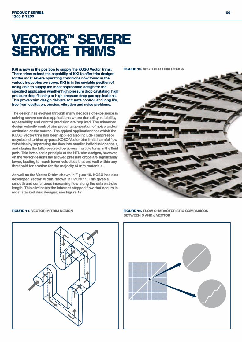
KKI is now in the position to supply the KOSO Vector trims.These trims extend the capability of KKI to offer trim designsfor the most severe operating conditions now found in thevarious industries we serve. KKI is in the enviable position ofbeing able to supply the most appropriate design for thespecified application whether high pressure drop cavitating, highpressure drop flashing or high pressure drop gas applications.This proven trim design delivers accurate control, and long life,free from cavitation, erosion, vibration and noise problems.
The design has evolved through many decades of experience insolving severe service applications where durability, reliability,repeatability and control precision are required. The advanceddesign velocity control trim prevents generation of noise and/orcavitation at the source. The typical applications for which theKOSO Vector trim has been applied also include compressorrecycle and turbine by-pass. KOSO Vector trim limits harmful flowvelocities by separating the flow into smaller individual channels,and staging the full pressure drop across multiple turns in the fluidpath. This is the basic principle of the HFL trim designs, however,on the Vector designs the allowed pressure drops are significantlylower, leading to much lower velocities that are well within anythreshold for erosion for the majority of trim materials.
As well as the Vector D trim shown in Figure 10. KOSO has alsodeveloped Vector M trim, shown in Figure 11. This gives asmooth and continuous increasing flow along the entire strokelength. This eliminates the inherent stepped flow that occurs inmost stacked disc designs, see Figure 12.
VECTORTM SEVERESERVICE TRIMS
FIGURE 10. VECTOR D TRIM DESIGN
FIGURE 11. VECTOR M TRIM DESIGN FIGURE 12. FLOW CHARACTERISTIC COMPARISONBETWEEN D AND J VECTOR
10
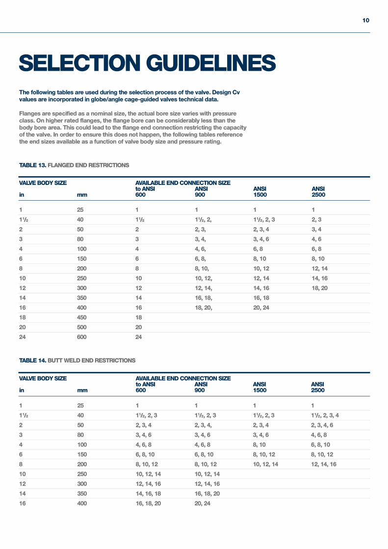
SELECTION GUIDELINESThe following tables are used during the selection process of the valve. Design Cvvalues are incorporated in globe/angle cage-guided valves technical data.
Flanges are specified as a nominal size, the actual bore size varies with pressureclass. On higher rated flanges, the flange bore can be considerably less than thebody bore area. This could lead to the flange end connection restricting the capacityof the valve. In order to ensure this does not happen, the following tables referencethe end sizes available as a function of valve body size and pressure rating.
VALVE BODY SIZE AVAILABLE END CONNECTION SIZEto ANSI ANSI ANSI ANSI
in mm 600 900 1500 2500
1 25 1 1 1 1
11/2 40 11/2 11/2, 2, 11/2, 2, 3 2, 3
2 50 2 2, 3, 2, 3, 4 3, 4
3 80 3 3, 4, 3, 4, 6 4, 6
4 100 4 4, 6, 6, 8 6, 8
6 150 6 6, 8, 8, 10 8, 10
8 200 8 8, 10, 10, 12 12, 14
10 250 10 10, 12, 12, 14 14, 16
12 300 12 12, 14, 14, 16 18, 20
14 350 14 16, 18, 16, 18
16 400 16 18, 20, 20, 24
18 450 18
20 500 20
24 600 24
TABLE 13. FLANGED END RESTRICTIONS
VALVE BODY SIZE AVAILABLE END CONNECTION SIZEto ANSI ANSI ANSI ANSI
in mm 600 900 1500 2500
1 25 1 1 1 1
11/2 40 11/2, 2, 3 11/2, 2, 3 11/2, 2, 3 11/2, 2, 3, 4
2 50 2, 3, 4 2, 3, 4, 2, 3, 4 2, 3, 4, 6
3 80 3, 4, 6 3, 4, 6 3, 4, 6 4, 6, 8
4 100 4, 6, 8 4, 6, 8 8, 10 6, 8, 10
6 150 6, 8, 10 6, 8, 10 8, 10, 12 8, 10, 12
8 200 8, 10, 12 8, 10, 12 10, 12, 14 12, 14, 16
10 250 10, 12, 14 10, 12, 14
12 300 12, 14, 16 12, 14, 16
14 350 14, 16, 18 16, 18, 20
16 400 16, 18, 20 20, 24
TABLE 14. BUTT WELD END RESTRICTIONS
PRODUCT SERIES1200 & 7200
11
LIQUIDS GASES/VAPOURSMAX ∆ P MAX ∆ P
TRIM DESIGN FLOW DIR. (BAR) (BAR)
HF UNDER 10 75*
OVER 50* 100
HFD UNDER 20 150*
OVER 95* 150
HFT UNDER 30 180*
OVER 125* 180
HF4 OVER 185 -
HF5 OVER 230 -
HFQ1 UNDER - 150
HFQ2 UNDER - 180
HFL – 2 UNDER 80 150
HFL – 3 UNDER 125 180
HFL – 4 UNDER 140 210
HFL – 5 UNDER 190 230
TABLE 16. PRESSURE DROP LIMITATIONS
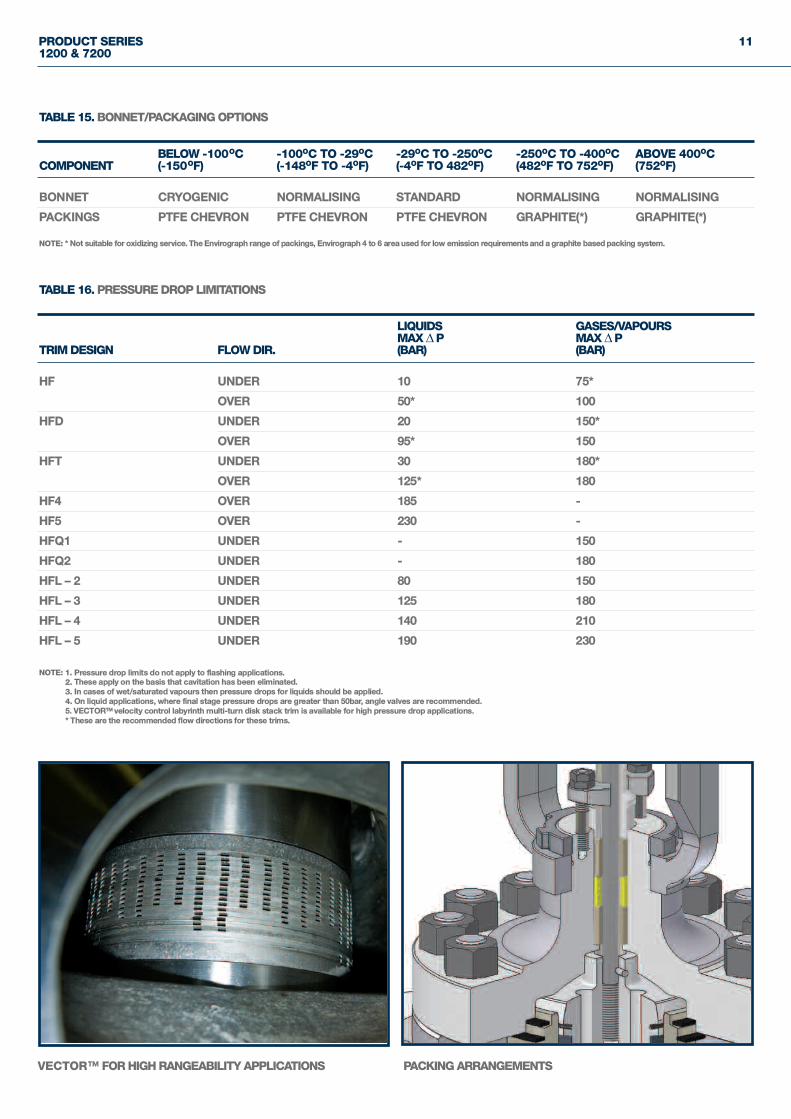
NOTE: * Not suitable for oxidizing service. The Envirograph range of packings, Envirograph 4 to 6 area used for low emission requirements and a graphite based packing system.
NOTE: 1. Pressure drop limits do not apply to flashing applications.2. These apply on the basis that cavitation has been eliminated.3. In cases of wet/saturated vapours then pressure drops for liquids should be applied.4. On liquid applications, where final stage pressure drops are greater than 50bar, angle valves are recommended.5. VECTORTM velocity control labyrinth multi-turn disk stack trim is available for high pressure drop applications.* These are the recommended flow directions for these trims.
BELOW -100OC -100OC TO -29OC -29OC TO -250OC -250OC TO -400OC ABOVE 400OCCOMPONENT (-150OF) (-148OF TO -4OF) (-4OF TO 482OF) (482OF TO 752OF) (752OF)
BONNET CRYOGENIC NORMALISING STANDARD NORMALISING NORMALISING
PACKINGS PTFE CHEVRON PTFE CHEVRON PTFE CHEVRON GRAPHITE(*) GRAPHITE(*)
TABLE 15. BONNET/PACKAGING OPTIONS
VECTOR™ FOR HIGH RANGEABILITY APPLICATIONS PACKING ARRANGEMENTS
12
TRIM SIZE HF SINGLE STAGE MULTI-STAGE DESIGNREF - in STANDARD RANGEABILITY STANDARD RANGEABILITY
1/4 TO 1/2 20: 1 15: 1
3/4 TO 1 30: 1 25: 1
11/2 TO 2 40: 1 35: 1
3 TO 6 50: 1 45: 1
8 TO 12 60: 1 55: 1
14 TO 24 70: 1 60: 1
ABOVE 24 80: 1 70: 1
TABLE 17. STANDARD RANGEABILITY VALVES
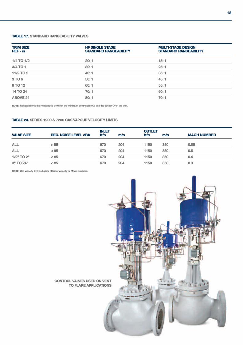
INLET OUTLETVALVE SIZE REQ. NOISE LEVEL dBA ft/s m/s ft/s m/s MACH NUMBER
ALL > 95 670 204 1150 350 0.65
ALL < 95 670 204 1150 350 0.5
1/2" TO 2" < 85 670 204 1150 350 0.4
3" TO 24" < 85 670 204 1150 350 0.3
TABLE 24. SERIES 1200 & 7200 GAS VAPOUR VELOCITY LIMITS
NOTE: Rangeability is the relationship between the minimum controllable Cv and the design Cv of the trim.
NOTE: Use velocity limit as higher of linear velocity or Mach numbers.
CONTROL VALVES USED ON VENTTO FLARE APPLICATIONS
PRODUCT SERIES1200 & 7200
13
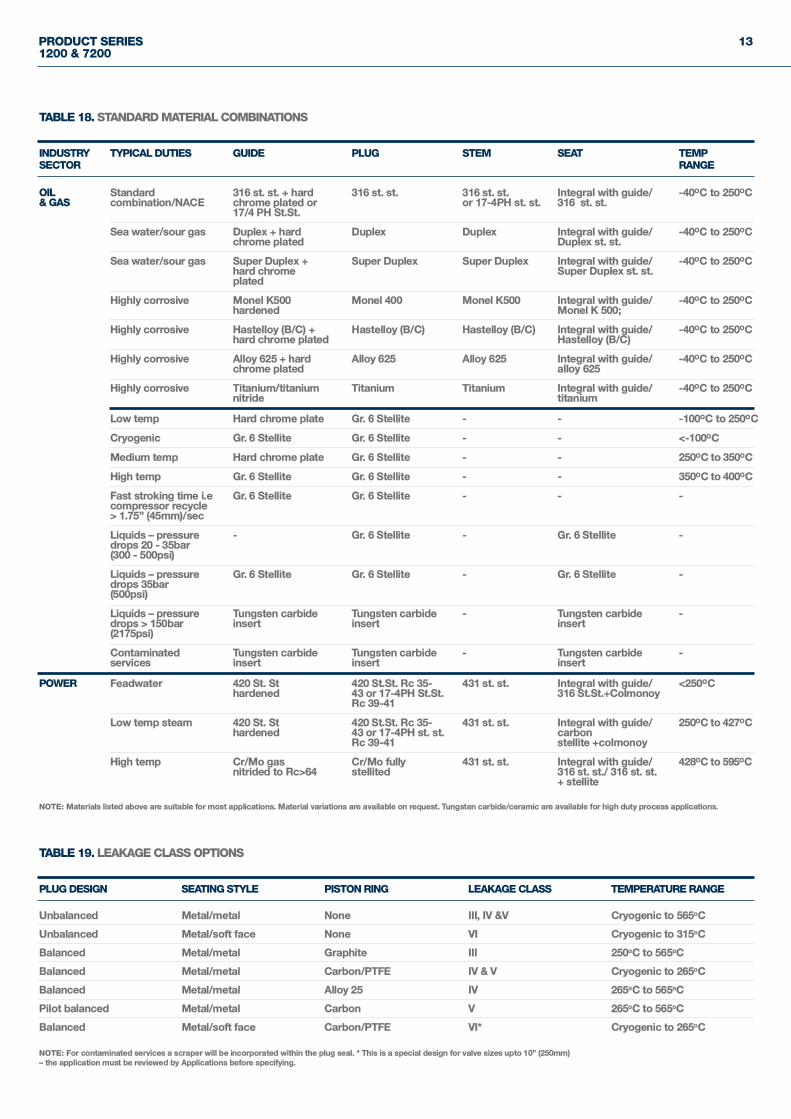
PLUG DESIGN SEATING STYLE PISTON RING LEAKAGE CLASS TEMPERATURE RANGE
Unbalanced Metal/metal None III, IV &V Cryogenic to 565oC
Unbalanced Metal/soft face None VI Cryogenic to 315oC
Balanced Metal/metal Graphite III 250oC to 565oC
Balanced Metal/metal Carbon/PTFE IV & V Cryogenic to 265oC
Balanced Metal/metal Alloy 25 IV 265oC to 565oC
Pilot balanced Metal/metal Carbon V 265oC to 565oC
Balanced Metal/soft face Carbon/PTFE VI* Cryogenic to 265oC
TABLE 19. LEAKAGE CLASS OPTIONS
NOTE: For contaminated services a scraper will be incorporated within the plug seal. * This is a special design for valve sizes upto 10” (250mm) – the application must be reviewed by Applications before specifying.
INDUSTRY TYPICAL DUTIES GUIDE PLUG STEM SEAT TEMPSECTOR RANGE
OIL Standard 316 st. st. + hard 316 st. st. 316 st. st. Integral with guide/ -40OC to 250OC& GAS combination/NACE chrome plated or or 17-4PH st. st. 316 st. st.
17/4 PH St.St.
Sea water/sour gas Duplex + hard Duplex Duplex Integral with guide/ -40OC to 250OCchrome plated Duplex st. st.
Sea water/sour gas Super Duplex + Super Duplex Super Duplex Integral with guide/ -40OC to 250OChard chrome Super Duplex st. st. plated
Highly corrosive Monel K500 Monel 400 Monel K500 Integral with guide/ -40OC to 250OChardened Monel K 500;
Highly corrosive Hastelloy (B/C) + Hastelloy (B/C) Hastelloy (B/C) Integral with guide/ -40OC to 250OChard chrome plated Hastelloy (B/C)
Highly corrosive Alloy 625 + hard Alloy 625 Alloy 625 Integral with guide/ -40OC to 250OCchrome plated alloy 625
Highly corrosive Titanium/titanium Titanium Titanium Integral with guide/ -40OC to 250OCnitride titanium
Low temp Hard chrome plate Gr. 6 Stellite - - -100OC to 250OC
Cryogenic Gr. 6 Stellite Gr. 6 Stellite - - <-100OC
Medium temp Hard chrome plate Gr. 6 Stellite - - 250OC to 350OC
High temp Gr. 6 Stellite Gr. 6 Stellite - - 350OC to 400OC
Fast stroking time i.e Gr. 6 Stellite Gr. 6 Stellite - - -compressor recycle> 1.75” (45mm)/sec
Liquids – pressure - Gr. 6 Stellite - Gr. 6 Stellite -drops 20 - 35bar(300 - 500psi)
Liquids – pressure Gr. 6 Stellite Gr. 6 Stellite - Gr. 6 Stellite -drops 35bar(500psi)
Liquids – pressure Tungsten carbide Tungsten carbide - Tungsten carbide -drops > 150bar insert insert insert(2175psi)
Contaminated Tungsten carbide Tungsten carbide - Tungsten carbide -services insert insert insert
POWER Feadwater 420 St. St 420 St.St. Rc 35- 431 st. st. Integral with guide/ <250OChardened 43 or 17-4PH St.St. 316 St.St.+Colmonoy
Rc 39-41
Low temp steam 420 St. St 420 St.St. Rc 35- 431 st. st. Integral with guide/ 250OC to 427OChardened 43 or 17-4PH st. st. carbon
Rc 39-41 stellite +colmonoy
High temp Cr/Mo gas Cr/Mo fully 431 st. st. Integral with guide/ 428OC to 595OCnitrided to Rc>64 stellited 316 st. st./ 316 st. st.
+ stellite
TABLE 18. STANDARD MATERIAL COMBINATIONS
NOTE: Materials listed above are suitable for most applications. Material variations are available on request. Tungsten carbide/ceramic are available for high duty process applications.
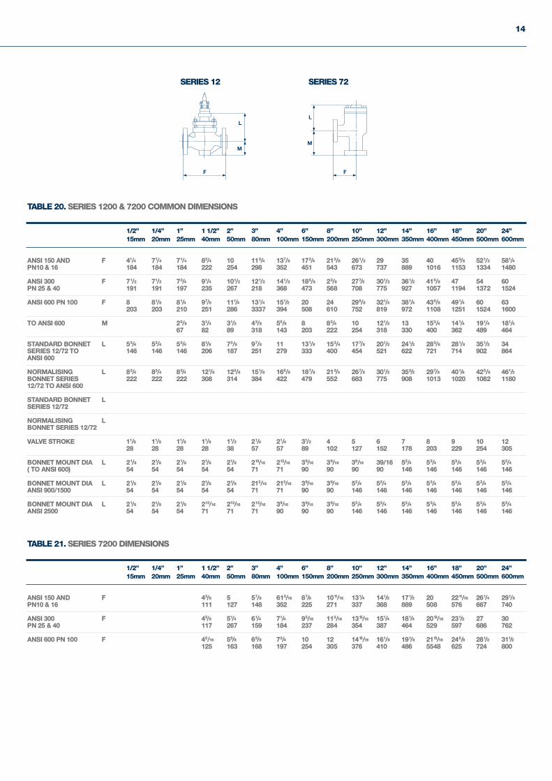
14
1/2” 1/4” 1” 1 1/2” 2” 3” 4” 6” 8” 10” 12” 14” 16” 18” 20” 24”15mm 20mm 25mm 40mm 50mm 80mm 100mm 150mm 200mm 250mm 300mm 350mm 400mm 450mm 500mm 600mm
ANSI 150 AND F 41/4 71/4 71/4 83/4 10 113/4 137/8 173/4 213/8 261/2 29 35 40 453/8 521/2 581/4PN10 & 16 184 184 184 222 254 298 352 451 543 673 737 889 1016 1153 1334 1480
ANSI 300 F 71/2 71/2 73/4 91/4 101/2 121/2 141/2 185/8 23/8 277/3 301/2 361/2 415/8 47 54 60PN 25 & 40 191 191 197 235 267 218 368 473 568 708 775 927 1057 1194 1372 1524
ANSI 600 PN 100 F 8 81/8 81/4 97/8 111/4 131/4 151/2 20 24 295/8 321/4 381/4 435/8 491/4 60 63203 203 210 251 286 3337 394 508 610 752 819 972 1108 1251 1524 1600
TO ANSI 600 M 25/8 31/4 31/2 43/8 55/8 8 83/4 10 121/2 13 153/4 141/4 191/4 181/467 82 89 318 143 203 222 254 318 330 400 362 489 464
STANDARD BONNET L 53/4 53/4 53/4 81/8 73/8 97/8 11 131/8 153/4 177/8 201/2 241/2 283/8 281/8 351/2 34SERIES 12/72 TO 146 146 146 206 187 251 279 333 400 454 521 622 721 714 902 864ANSI 600
NORMALISING L 83/4 83/4 83/4 121/8 123/8 151/8 165/8 187/8 213/4 267/8 301/2 353/2 297/8 401/6 425/8 461/2BONNET SERIES 222 222 222 308 314 384 422 479 552 683 775 908 1013 1020 1082 118012/72 TO ANSI 600
STANDARD BONNET LSERIES 12/72
NORMALISING LBONNET SERIES 12/72
VALVE STROKE 11/8 11/8 11/8 11/8 11/2 21/4 21/4 31/2 4 5 6 7 8 9 10 1228 28 28 28 38 57 57 89 102 127 152 178 203 229 254 305
BONNET MOUNT DIA L 21/8 21/8 21/8 21/8 21/8 213/16 213/16 39/16 39/16 39/16 39/16 53/4 53/4 53/4 53/4 53/4( TO ANSI 600) 54 54 54 54 54 71 71 90 90 90 90 146 146 146 146 146
BONNET MOUNT DIA L 21/8 21/8 21/8 21/8 21/8 213/16 213/16 39/16 39/16 53/4 53/4 53/4 53/4 53/4 53/4 53/4ANSI 900/1500 54 54 54 54 54 71 71 90 90 146 146 146 146 146 146 146
BONNET MOUNT DIA L 21/8 21/8 21/8 213/16 213/16 213/16 39/16 39/15 39/16 53/4 53/4 53/4 53/4 53/4 53/4 53/4ANSI 2500 54 54 54 71 71 71 90 90 90 146 146 146 146 146 146 146
TABLE 20. SERIES 1200 & 7200 COMMON DIMENSIONS
1/2” 1/4” 1” 1 1/2” 2” 3” 4” 6” 8” 10” 12” 14” 16” 18” 20” 24”15mm 20mm 25mm 40mm 50mm 80mm 100mm 150mm 200mm 250mm 300mm 350mm 400mm 450mm 500mm 600mm
ANSI 150 AND F 43/8 5 57/8 615/16 87/8 1011/16 131/4 141/2 171/2 20 2211/16 261/4 291/8PN10 & 16 111 127 148 352 225 271 337 368 889 508 576 667 740
ANSI 300 F 45/8 51/4 61/4 71/4 95/16 113/16 1315/16 151/4 181/4 2013/16 231/2 27 30PN 25 & 40 117 267 159 184 237 284 354 387 464 529 597 686 762
ANSI 600 PN 100 F 45/16 55/8 65/8 73/4 10 12 1415/16 161/8 191/8 2113/16 245/8 281/2 311/2125 163 168 197 254 305 376 410 486 5548 625 724 800
TABLE 21. SERIES 7200 DIMENSIONS
SERIES 72SERIES 12
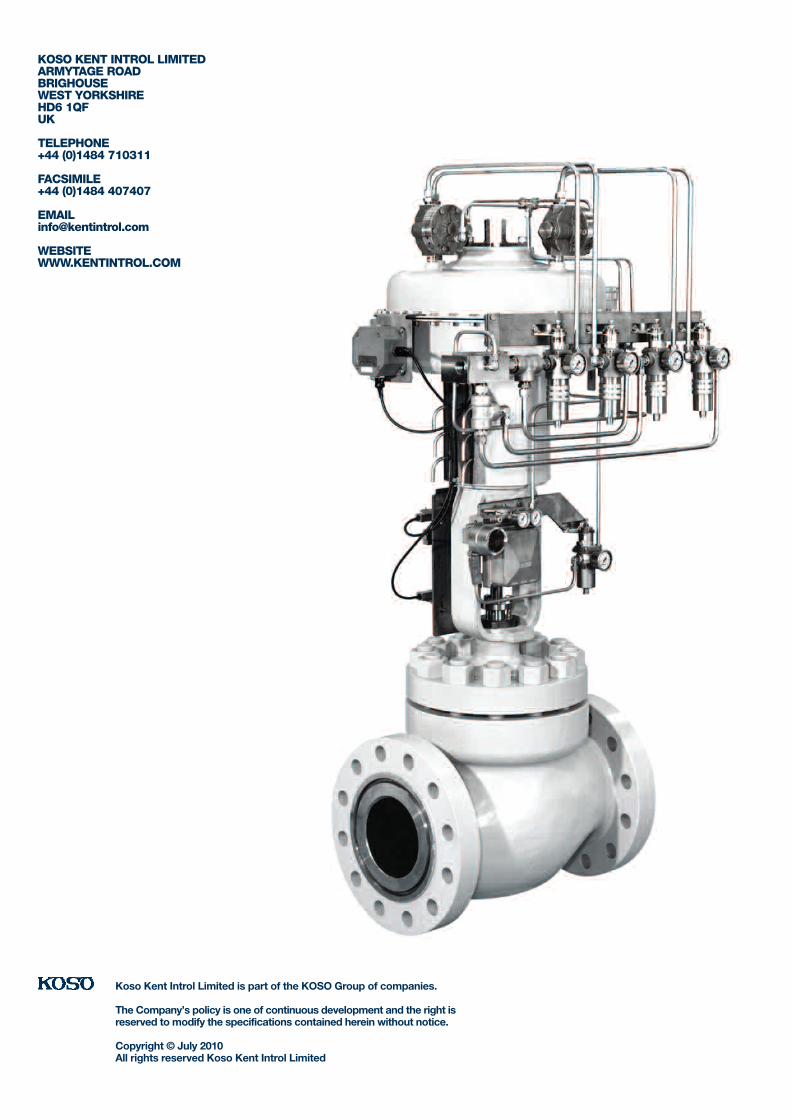
KOSO KENT INTROL LIMITEDARMYTAGE ROADBRIGHOUSEWEST YORKSHIREHD6 1QFUK
TELEPHONE+44 (0)1484 710311
FACSIMILE+44 (0)1484 407407
WEBSITE WWW.KENTINTROL.COM
Koso Kent Introl Limited is part of the KOSO Group of companies.
The Company’s policy is one of continuous development and the right isreserved to modify the specifications contained herein without notice.
Copyright © July 2010All rights reserved Koso Kent Introl Limited


![D1 Series Top Guided Single Seated Control Valves - Azbil · D1 Series Top Guided Single Seated Control Valves ... 300, 600 PN 25, ... mm] Nominal size (inches) F/F Class 150RF](https://img.pdfslide.us/doc/110x75/5b0928677f8b9ac90f8da5ca/d1-series-top-guided-single-seated-control-valves-series-top-guided-single-seated.jpg)