Embed Size (px)
Citation preview
www.Fisher.com
Fisher� YD and YS Control ValvesFisher YD (figure 1) and YS three-way cage-guidedvalves are designed for throttling or flow-switching(on-off) service, and are available in the followingconstructions:
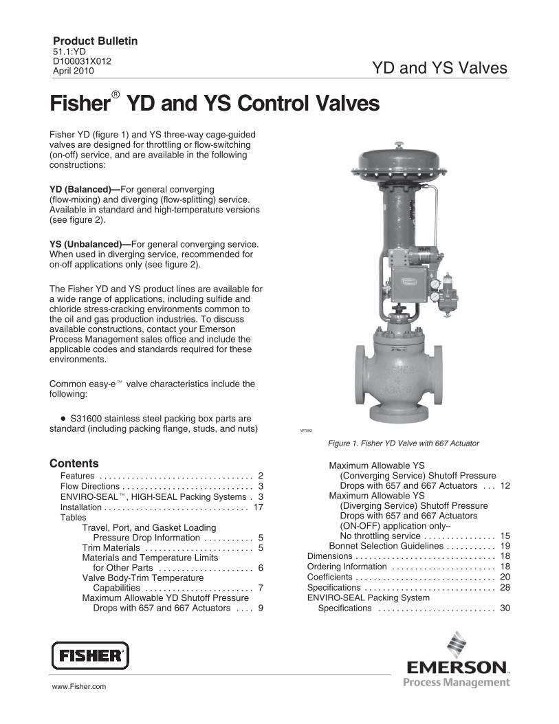
YD (Balanced)—For general converging(flow-mixing) and diverging (flow-splitting) service.Available in standard and high-temperature versions(see figure 2).
YS (Unbalanced)—For general converging service.When used in diverging service, recommended foron-off applications only (see figure 2).
The Fisher YD and YS product lines are available fora wide range of applications, including sulfide andchloride stress-cracking environments common tothe oil and gas production industries. To discussavailable constructions, contact your EmersonProcess Management sales office and include theapplicable codes and standards required for theseenvironments.
Common easy-e� valve characteristics include thefollowing:
� S31600 stainless steel packing box parts arestandard (including packing flange, studs, and nuts)
ContentsFeatures 2. . . . . . . . . . . . . . . . . . . . . . . . . . . . . . . . . . Flow Directions 3. . . . . . . . . . . . . . . . . . . . . . . . . . . . . ENVIRO-SEAL�, HIGH-SEAL Packing Systems 3. Installation 17. . . . . . . . . . . . . . . . . . . . . . . . . . . . . . . . Tables
Travel, Port, and Gasket Loading Pressure Drop Information 5. . . . . . . . . . .
Trim Materials 5. . . . . . . . . . . . . . . . . . . . . . . . Materials and Temperature Limits
for Other Parts 6. . . . . . . . . . . . . . . . . . . . . Valve Body-Trim Temperature
Capabilities 7. . . . . . . . . . . . . . . . . . . . . . . . Maximum Allowable YD Shutoff Pressure
Drops with 657 and 667 Actuators 9. . . .
W7593
Figure 1. Fisher YD Valve with 667 Actuator
Maximum Allowable YS (Converging Service) Shutoff PressureDrops with 657 and 667 Actuators 12. . .
Maximum Allowable YS (Diverging Service) Shutoff PressureDrops with 657 and 667 Actuators(ON-OFF) application only--No throttling service 15. . . . . . . . . . . . . . . .
Bonnet Selection Guidelines 19. . . . . . . . . . . Dimensions 18. . . . . . . . . . . . . . . . . . . . . . . . . . . . . . . Ordering Information 18. . . . . . . . . . . . . . . . . . . . . . . Coefficients 20. . . . . . . . . . . . . . . . . . . . . . . . . . . . . . . Specifications 28. . . . . . . . . . . . . . . . . . . . . . . . . . . . . ENVIRO-SEAL Packing System
Specifications 30. . . . . . . . . . . . . . . . . . . . . . . . . .
Product Bulletin51.1:YDD100031X012April 2010 YD and YS Valves
YD and YS ValvesProduct Bulletin
51.1:YDApril 2010
2
CAGEO-RING
LOWERCAGE
VALVEPLUG
SEATRING
LOWERSEATRING
VALVEPLUG
UPPERCAGE REVERSIBLE
UPPERSEAT RING
SEALRING
BACKUPRING
SEAT RINGGASKET
RETAININGRINGGASKETS
LOWERCAGE
UPPERCAGE
VALVEPLUGSEALS
RETAININGRING
UPPERSEAT RINGGASKET
LOWERSEAT RINGGASKET
STANDARD YD
DETAIL OF HIGH TEMPERATUREYD TRIM
YS
W9045�1 / IL
40A3551�CA1891�1 / IL
W9046�1 / IL
SPRING
Figure 2. Construction Details
58B1505�A
STEM
UPPERCAGE
LOWERCAGE
ADAPTORFLANGE
PLUG
CAGEADAPTOR
BONNET
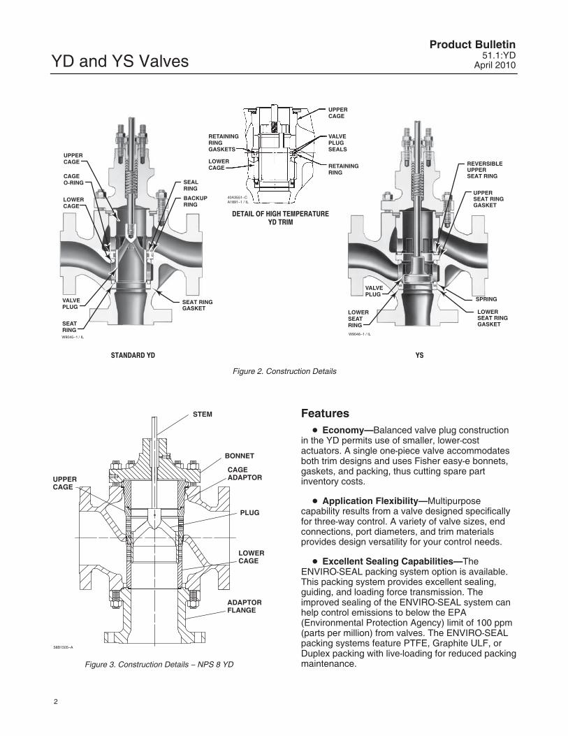
Figure 3. Construction Details � NPS 8 YD
Features� Economy—Balanced valve plug construction
in the YD permits use of smaller, lower-costactuators. A single one-piece valve accommodatesboth trim designs and uses Fisher easy-e bonnets,gaskets, and packing, thus cutting spare partinventory costs.
� Application Flexibility—Multipurposecapability results from a valve designed specificallyfor three-way control. A variety of valve sizes, endconnections, port diameters, and trim materialsprovides design versatility for your control needs.
� Excellent Sealing Capabilities—TheENVIRO-SEAL packing system option is available.This packing system provides excellent sealing,guiding, and loading force transmission. Theimproved sealing of the ENVIRO-SEAL system canhelp control emissions to below the EPA(Environmental Protection Agency) limit of 100 ppm(parts per million) from valves. The ENVIRO-SEALpacking systems feature PTFE, Graphite ULF, orDuplex packing with live-loading for reduced packingmaintenance.
YD and YS ValvesProduct Bulletin51.1:YDApril 2010
3
� Long Trim Life—Hardened trim materialsprovide excellent wear resistance.
� Easy Maintenance—Cage-type constructionsimplifies inspection and removal of parts.
� Valve Plug Stability— Rugged cage guidingprovides high valve plug stability, which reducesvibration and mechanical noise.
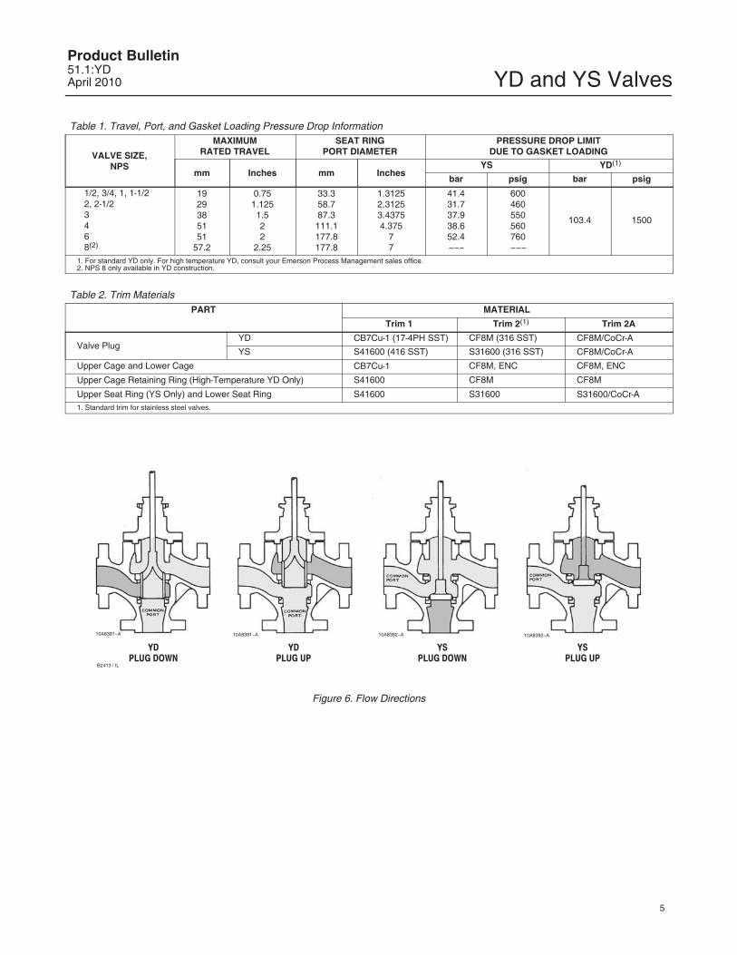
Flow Directions
YD (Common Port on Bottom) see figure 6
� Plug Down, Left-Hand Port Closed—Flow inconverging service is from right to bottom port and indiverging service is from bottom to right port.
� Plug Up, Right-Hand Port Closed—Flow inconverging service is from left to bottom port and indiverging service is from bottom to left port.
� Intermediate Plug Positions—Flow inconverging service is from both left and right ports tobottom port, with capacities in proportion to plugtravel. Flow in diverging service is from bottom portto both left and right ports, with capacities split inproportion to plug travel.
YS (Common Port on Left) see figure 6
� Plug Down, Bottom Port Closed—Flow inconverging service is from right to left port and indiverging service is from left to right port.
� Plug Up, Right-Hand Port Closed—Flow inconverging service is from bottom to left port and indiverging service is from left to bottom port.
� Intermediate Plug Positions—Flow inconverging service is from both bottom and rightports to left port, with capacities in proportion to plugtravel.
W5852�1 / IL
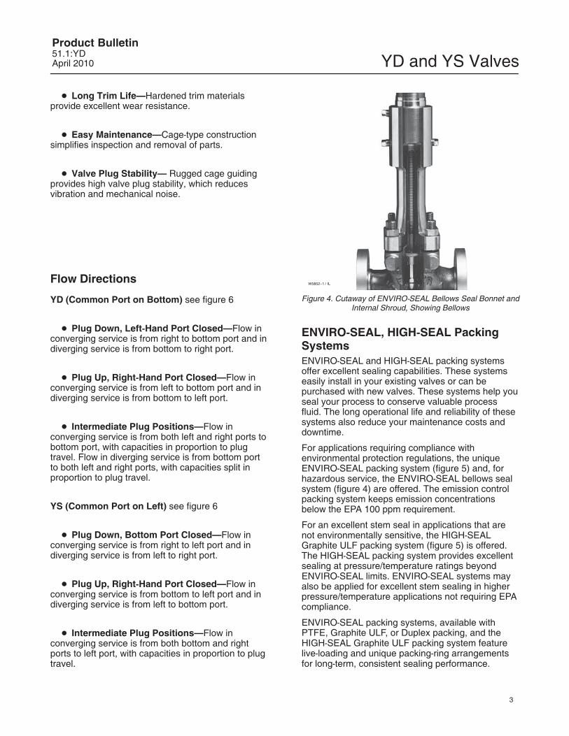
Figure 4. Cutaway of ENVIRO-SEAL Bellows Seal Bonnet andInternal Shroud, Showing Bellows
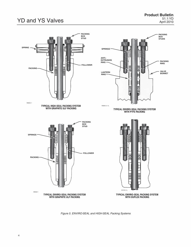
ENVIRO-SEAL, HIGH-SEAL PackingSystemsENVIRO-SEAL and HIGH-SEAL packing systemsoffer excellent sealing capabilities. These systemseasily install in your existing valves or can bepurchased with new valves. These systems help youseal your process to conserve valuable processfluid. The long operational life and reliability of thesesystems also reduce your maintenance costs anddowntime.
For applications requiring compliance withenvironmental protection regulations, the uniqueENVIRO-SEAL packing system (figure 5) and, forhazardous service, the ENVIRO-SEAL bellows sealsystem (figure 4) are offered. The emission controlpacking system keeps emission concentrationsbelow the EPA 100 ppm requirement.
For an excellent stem seal in applications that arenot environmentally sensitive, the HIGH-SEALGraphite ULF packing system (figure 5) is offered.The HIGH-SEAL packing system provides excellentsealing at pressure/temperature ratings beyondENVIRO-SEAL limits. ENVIRO-SEAL systems mayalso be applied for excellent stem sealing in higherpressure/temperature applications not requiring EPAcompliance.
ENVIRO-SEAL packing systems, available withPTFE, Graphite ULF, or Duplex packing, and theHIGH-SEAL Graphite ULF packing system featurelive-loading and unique packing-ring arrangementsfor long-term, consistent sealing performance.
YD and YS ValvesProduct Bulletin
51.1:YDApril 2010
4
TYPICAL ENVIRO-SEAL PACKING SYSTEMWITH DUPLEX PACKING
W5803�3 / IL
SPRINGS
ANTI�EXTRUSIONRING
LANTERNRING
PACKINGBOXSTUDS
PACKINGRING
VALVEBONNET
TYPICAL ENVIRO-SEAL PACKING SYSTEMWITH GRAPHITE ULF PACKING
TYPICAL ENVIRO-SEAL PACKING SYSTEMWITH PTFE PACKING
TYPICAL HIGH-SEAL PACKING SYSTEMWITH GRAPHITE ULF PACKING
W7018 / IL
W8533�1
PACKINGBOXSTUD
FOLLOWER
PACKING
SPRING
W8532-1
FOLLOWER
PACKINGBOXSTUD
PACKING
SPRINGS
Figure 5. ENVIRO-SEAL and HIGH-SEAL Packing Systems
YD and YS ValvesProduct Bulletin51.1:YDApril 2010
5
Table 1. Travel, Port, and Gasket Loading Pressure Drop Information
VALVE SIZE,NPS
MAXIMUMRATED TRAVEL
SEAT RINGPORT DIAMETER
PRESSURE DROP LIMITDUE TO GASKET LOADING
mm Inches mm InchesYS YD(1)
bar psig bar psig
1/2, 3/4, 1, 1-1/22, 2-1/23468(2)
1929385151
57.2
0.751.1251.522
2.25
33.358.787.3111.1177.8177.8
1.31252.31253.43754.375
77
41.431.737.938.652.4���
600460550560760���
103.4 1500
1. For standard YD only. For high temperature YD, consult your Emerson Process Management sales office.2. NPS 8 only available in YD construction.
Table 2. Trim MaterialsPART MATERIAL
Trim 1 Trim 2(1) Trim 2A
Valve PlugYD CB7Cu-1 (17-4PH SST) CF8M (316 SST) CF8M/CoCr-A
YS S41600 (416 SST) S31600 (316 SST) CF8M/CoCr-A
Upper Cage and Lower Cage CB7Cu-1 CF8M, ENC CF8M, ENC
Upper Cage Retaining Ring (High-Temperature YD Only) S41600 CF8M CF8M
Upper Seat Ring (YS Only) and Lower Seat Ring S41600 S31600 S31600/CoCr-A1. Standard trim for stainless steel valves.
10A8391�A 10A8391�A 10A8392�A 10A8392�A
B2413 / IL
YDPLUG DOWN
YDPLUG UP
YSPLUG UP
YSPLUG DOWN
Figure 6. Flow Directions
YD and YS ValvesProduct Bulletin
51.1:YDApril 2010
6
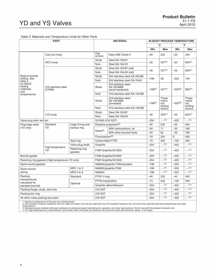
Table 3. Materials and Temperature Limits for Other PartsPART MATERIAL IN-BODY PROCESS TEMPERATURE
�C �F
Min Max Min Max
Body-to-bonnetbolting. Seetable 4for NACEboltingmaterialsandtemperatures
Cast iron body Capscrews Steel SAE Grade 5 �29 232 �20 450
WCC bodyStuds Steel SA-193-B7
�29 427(1) �20 800(1)Nuts Steel SA-194-2H
316 stainless steel(CF8M)
Studs Steel SA-193-B7 (std)�48 427(1) �55 800(1)
Nuts Steel SA-194-2H (std)
Studs 304 stainless steel SA-320-B8�198 38 �325 100
Nuts 304 stainless steel SA-194-8
Studs316 stainless steelSA-193-B8M(strain-hardened) �198(2) 427(1) �325(2) 800(1)
Nuts 316 stainless steel SA-194-8M
Studs316 stainless steelSA-194-B8M(annealed) �198(2)
Thesemat’lsnotlimitingfactors
�325(2)
Thesemat’lsnotlimitingfactorsNuts 316 stainless steel SA-194-8M
LCC bodyStuds Steel SA-193-B7
�46 343(1) �50 650(1)Nuts Steel SA-194-2H
Valve plug stem and pin S31600 (316 SST) �254 - - -(1) �425 - - -(1)
Plug-cage seals(YD only)
StandardYD
Cage O-ring andbackup ring
Ethylene propylene(2) �40 232 �40 450
Nitrile(3)With hydrocarbons, air �34 71 �30 160
With other process fluids �34 82 �30 180
Fluorocarbon(4) �18 204 0 400
Seal ring Carbon-filled PTFE �73 232 �100 450
High-temperatureYD
Valve plug seals Graphite �254 - - -(1) �425 - - -(1)
Retaining ringgaskets
FGM Graphite/S31600 �254 - - -(1) �425 - - -(1)
Bonnet gasket FGM Graphite/S31600 �254 - - -(1) �425 - - -(1)
Retaining ring gaskets (High-temperature YD only) FGM Graphite/S31600 �254 - - -(1) �425 - - -(1)
Spiral wound gaskets N06600/graphite FGM-standard �198 - - -(1) �325 - - -(1)
Spiral woundspring
NPS 1 to 3 N06600/graphite FGM �198 - - -(1) �325 - - -(1)
NPS 4 to 8 N06600 �198 - - -(1) �325 - - -(1)
Packing(temperaturescalculated forstandard bonnet)
Standard PTFE V-ring �40 232 �40 450
OptionalPTFE/composition �73 232 �100 450
Graphite ribbon/filament �254 - - -(1) �425 - - -(1)
Packing flange, studs, and nuts 316 SST �254 - - -(1) �425 - - -(1)
Packing box ring 316 SST �254 - - -(1) �425 - - -(1)
All other metal packing box parts 316 SST �254 - - -(1) �425 - - -(1)
1. Maximum temperature of this part not a limiting factor.2. Has excellent moisture resistance with hot water and steam and may be used with most fire-resistant hydraulic oils, but cannot be used with petroleum-based fluids and otherhydrocarbons.3. General-purpose material with good resistance to petroleum-based lubricating oils, gasoline, and other hydrocarbons. Not for use with fire-resistant hydraulic oils.4. For high-temperature air, hydrocarbons, and certain other chemicals and solvents, but cannot be used with ammonia, steam, or hot water.
YD and YS ValvesProduct Bulletin51.1:YDApril 2010
7
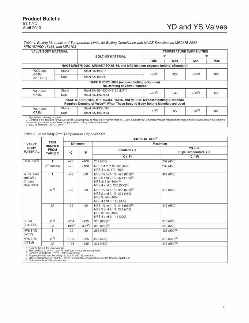
Table 4. Bolting Materials and Temperature Limits for Bolting Compliance with NACE Specification MR0175-2002, MR0157/ISO 15156, and MR0103
VALVE BODY MATERIAL
BOLTING MATERIAL
TEMPERATURE CAPABILITIES
�C �F
Min Max Min Max
NACE MR0175-2002, MR0157/ISO 15156, and MR0103 (non-exposed bolting) (Standard)
WCC andCF8M(316 SST)
Studs Steel SA-193-B7�48(3) 427 �55(3) 800
Nuts Steel SA-194-2H
NACE MR0175-2002 (exposed bolting) (Optional)No Derating of Valve Required
WCC andCF8M
Studs Steel SA-564-630 (H1150 dbl(1))�46(3) 343 �50(3) 650
Nuts Steel SA-194-2HM
NACE MR0175-2002, MR0157/ISO 15156, and MR0103 (exposed bolting) (Optional)Requires Derating of Valve(2) When These Body-to-Body Bolting Materials are Used
WCC andCF8M
Studs Steel SA-193-B7M�48(3) 427 �55(3) 800
Nuts Steel SA-194-2HM1. Special heat treating required.2. Derating is not required for CL300 valves. Derating may be required for valves rated at CL600. Contact your Emerson Process Management sales office for assistance in determiningthe derating of valves when these body-to-bonnet bolting materials are used.3. WCC is limited to �29�C (�20�F).
Table 5. Valve Body-Trim Temperature Capabilities(1)
VALVEBODY
MATERIAL
TRIMNUMBER
FROMTABLE 2
TEMPERATURE(2)
Minimum Maximum
�C �FStandard YD YS and
High-Temperature YD
�C (�F) �C (�F)
Cast Iron(3) 1 �73 �100 232 (450) 232 (450)
2(2) and 2A �73 �100 NPS 1-1/2 to 3: 232 (450)NPS 4 to 6: 177 (350)
232 (450)
WCC Steeland WC9ChromeMoly Steel
1 �29 �20 NPS 1/2 to 1-1/2: 427 (800)(4)
NPS 2 and 2-1/2: 371 (700)(4)
NPS 3: 316 (600)(4)
NPS 4 and 6: 260 (500)(4)
427 (800)
2(2) �29 �20 NPS 1/2 to 1-1/2: 316 (600)(4)
NPS 2 and 2-1/2: 232 (450)NPS 3: 204 (400)NPS 4 and 6: 149 (300)
316 (600)
2A �29 �20 NPS 1/2 to 1-1/2: 343 (650)(4)
NPS 2 and 2-1/2: 232 (450)NPS 3: 204 (400)NPS 4 and 6: 149 (300)
343 (650)
CF8M(316 SST)
2(2) �254 �425 316 (600)(4) 316 (600)
2A �198(5) �325(5) 343 (650)(4) 343 (650)
NPS 8 YD(WCC)
1 �29 �20 232 (450) 427 (800)(6)
NPS 8 YD(CF8M)
2(2) �198 �325 232 (450) 316 (600)(6)
2A �198 �325 232 (450) 343 (650)(6)
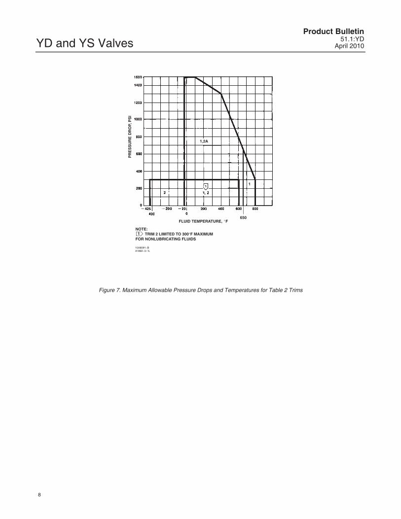
1. Refer to table 2 for trim materials.2. Trim 2 limited to 149�C (300�F) maximum for nonlubricating fluids.3. Cast iron is limited to �73�C (�100�F) minimum4. Plug-cage seals limit this design to 232�C (450�F) maximum.5. May be used down to �254�C (�425�F) if manufacturing process includes Charpy impact test.6. Only available in YD constructions.
YD and YS ValvesProduct Bulletin
51.1:YDApril 2010
8
FLUID TEMPERATURE, �F
PR
ES
SU
RE
DR
OP,
PS
I
1NOTE:
TRIM 2 LIMITED TO 300�F MAXIMUMFOR NONLUBRICATING FLUIDS
10A8091�BA1892�3 / IL
1,2A
1
650
Figure 7. Maximum Allowable Pressure Drops and Temperatures for Table 2 Trims
YD and YS ValvesProduct Bulletin51.1:YDApril 2010
9
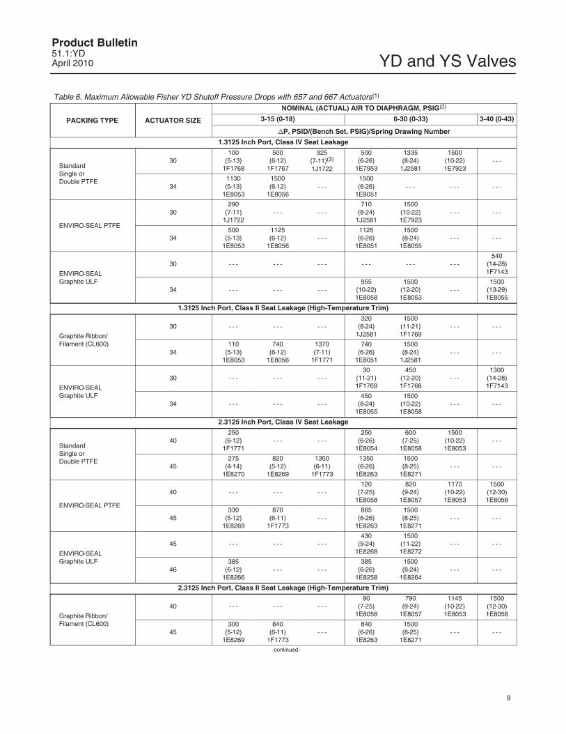
Table 6. Maximum Allowable Fisher YD Shutoff Pressure Drops with 657 and 667 Actuators(1)
PACKING TYPE ACTUATOR SIZE
NOMINAL (ACTUAL) AIR TO DIAPHRAGM, PSIG(2)
3-15 (0-18) 6-30 (0-33) 3-40 (0-43)
�P, PSID/(Bench Set, PSIG)/Spring Drawing Number
1.3125 Inch Port, Class IV Seat Leakage
Standard Single or Double PTFE
30100
(5-13)1F1768
500(6-12)
1F1767
925(7-11)(3)
1J1722
500(6-26)
1E7953
1335(8-24)
1J2581
1500(10-22)1E7923
- - -
341130(5-13)
1E8053
1500(6-12)
1E8056- - -
1500(6-26)
1E8051- - - - - - - - -
ENVIRO-SEAL PTFE
30290
(7-11)1J1722
- - - - - -710
(8-24)1J2581
1500(10-22)1E7923
- - - - - -
34500
(5-13)1E8053
1125(6-12)
1E8056- - -
1125(6-26)
1E8051
1500(8-24)
1E8055- - - - - -
ENVIRO-SEAL Graphite ULF
30 - - - - - - - - - - - - - - - - - -540
(14-28)1F7143
34 - - - - - - - - -955
(10-22)1E8058
1500(12-20)1E8053
- - -1500
(13-29)1E8055
1.3125 Inch Port, Class II Seat Leakage (High-Temperature Trim)
Graphite Ribbon/Filament (CL600)
30 - - - - - - - - -320
(8-24)1J2581
1500(11-21)1F1769
- - - - - -
34110
(5-13)1E8053
740(6-12)
1E8056
1370(7-11)
1F1771
740(6-26)
1E8051
1500(8-24)
1J2581- - - - - -
ENVIRO-SEAL Graphite ULF
30 - - - - - - - - -30
(11-21)1F1769
450(12-20)1F1768
- - -1300
(14-28)1F7143
34 - - - - - - - - -450
(8-24)1E8055
1500(10-22)1E8058
- - - - - -
2.3125 Inch Port, Class IV Seat Leakage
StandardSingle orDouble PTFE
40250
(6-12)1F1771
- - - - - -250
(6-26)1E8054
600(7-25)
1E8058
1500(10-22)1E8053
- - -
45275
(4-14)1E8270
820(5-12)
1E8269
1350(6-11)
1F1773
1350(6-26)
1E8263
1500(8-25)
1E8271- - - - - -
ENVIRO-SEAL PTFE
40 - - - - - - - - -120
(7-25)1E8058
820(9-24)
1E8057
1170(10-22)1E8053
1500(12-30)1E8058
45330
(5-12)1E8269
870(6-11)
1F1773- - -
865(6-26)
1E8263
1500(8-25)
1E8271- - - - - -
ENVIRO-SEAL Graphite ULF
45 - - - - - - - - -430
(9-24)1E8268
1500(11-22)1E8272
- - - - - -
46385
(6-12)1E8266
- - - - - -385
(6-26)1E8258
1500(8-24)
1E8264- - - - - -
2.3125 Inch Port, Class II Seat Leakage (High-Temperature Trim)
Graphite Ribbon/Filament (CL600)
40 - - - - - - - - -90
(7-25)1E8058
790(9-24)
1E8057
1145(10-22)1E8053
1500(12-30)1E8058
45300
(5-12)1E8269
840(6-11)
1F1773- - -
840(6-26)
1E8263
1500(8-25)
1E8271- - - - - -
-continued-
YD and YS ValvesProduct Bulletin
51.1:YDApril 2010
10
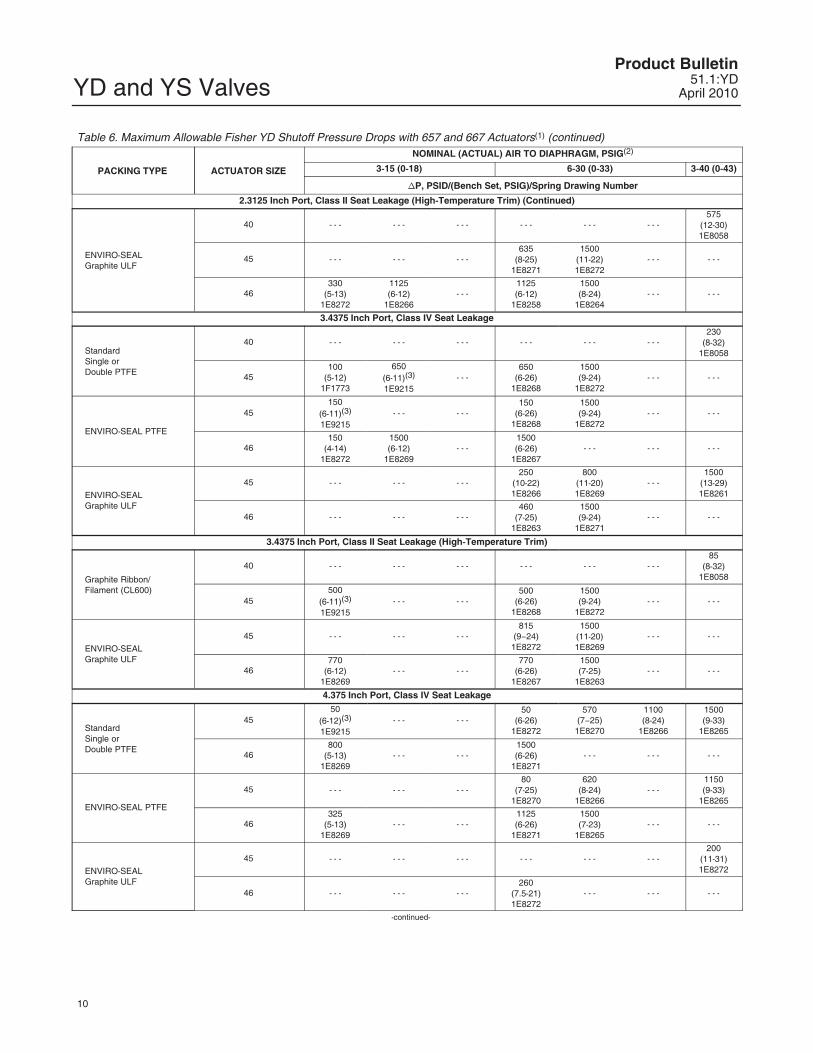
Table 6. Maximum Allowable Fisher YD Shutoff Pressure Drops with 657 and 667 Actuators(1) (continued)
PACKING TYPE ACTUATOR SIZE
NOMINAL (ACTUAL) AIR TO DIAPHRAGM, PSIG(2)
3-15 (0-18) 6-30 (0-33) 3-40 (0-43)
�P, PSID/(Bench Set, PSIG)/Spring Drawing Number
2.3125 Inch Port, Class II Seat Leakage (High-Temperature Trim) (Continued)
ENVIRO-SEAL Graphite ULF
40 - - - - - - - - - - - - - - - - - -575
(12-30)1E8058
45 - - - - - - - - -635
(8-25)1E8271
1500(11-22)1E8272
- - - - - -
46330
(5-13)1E8272
1125(6-12)
1E8266- - -
1125(6-12)
1E8258
1500(8-24)
1E8264- - - - - -
3.4375 Inch Port, Class IV Seat Leakage
StandardSingle orDouble PTFE
40 - - - - - - - - - - - - - - - - - -230
(8-32)1E8058
45100
(5-12)1F1773
650(6-11)(3)
1E9215- - -
650(6-26)
1E8268
1500(9-24)
1E8272- - - - - -
ENVIRO-SEAL PTFE
45150
(6-11)(3)
1E9215- - - - - -
150(6-26)
1E8268
1500(9-24)
1E8272- - - - - -
46150
(4-14)1E8272
1500(6-12)
1E8269- - -
1500(6-26)
1E8267- - - - - - - - -
ENVIRO-SEAL Graphite ULF
45 - - - - - - - - -250
(10-22)1E8266
800(11-20)1E8269
- - -1500
(13-29)1E8261
46 - - - - - - - - -460
(7-25)1E8263
1500(9-24)
1E8271- - - - - -
3.4375 Inch Port, Class II Seat Leakage (High-Temperature Trim)
Graphite Ribbon/Filament (CL600)
40 - - - - - - - - - - - - - - - - - -85
(8-32)1E8058
45500
(6-11)(3)
1E9215- - - - - -
500(6-26)
1E8268
1500(9-24)
1E8272- - - - - -
ENVIRO-SEAL Graphite ULF
45 - - - - - - - - -815
(9�24)1E8272
1500(11-20)1E8269
- - - - - -
46770
(6-12)1E8269
- - - - - -770
(6-26)1E8267
1500(7-25)
1E8263- - - - - -
4.375 Inch Port, Class IV Seat Leakage
StandardSingle orDouble PTFE
4550
(6-12)(3)
1E9215- - - - - -
50(6-26)
1E8272
570(7�25)
1E8270
1100(8-24)
1E8266
1500(9-33)
1E8265
46800
(5-13)1E8269
- - - - - -1500(6-26)
1E8271- - - - - - - - -
ENVIRO-SEAL PTFE
45 - - - - - - - - -80
(7-25)1E8270
620(8-24)
1E8266- - -
1150(9-33)
1E8265
46325
(5-13)1E8269
- - - - - -1125(6-26)
1E8271
1500(7-23)
1E8265- - - - - -
ENVIRO-SEAL Graphite ULF
45 - - - - - - - - - - - - - - - - - -200
(11-31)1E8272
46 - - - - - - - - -260
(7.5-21)1E8272
- - - - - - - - -
-continued-
YD and YS ValvesProduct Bulletin51.1:YDApril 2010
11
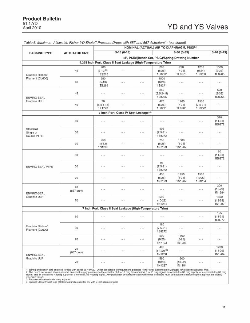
Table 6. Maximum Allowable Fisher YD Shutoff Pressure Drops with 657 and 667 Actuators(1) (continued)
PACKING TYPE ACTUATOR SIZE
NOMINAL (ACTUAL) AIR TO DIAPHRAGM, PSIG(2)
3-15 (0-18) 6-30 (0-33) 3-40 (0-43)
�P, PSID/(Bench Set, PSIG)/Spring Drawing Number
4.375 Inch Port, Class II Seat Leakage (High-Temperature Trim)
Graphite Ribbon/Filament (CL600)
45200
(6-12)(3)
1E9215- - - - - -
200(6-26)
1E8272
720(7-25)
1E8270
1250(8-24)
1E8266
1500(9-33)
1E8265
46950
(5-13)1E8269
- - - - - -1500(6-26)
1E8271- - - - - - - - -
ENVIRO-SEAL Graphite ULF
45 - - - - - - - - -250
(8.5-24.5)1E8266
- - - - - -520
(9-33)1E8265
4670
(5.5-11.5)1F1773
- - - - - -470
(6-26)1E8271
1260(7-23)
1E8265
1500(7.5-21)1E8272
- - -
7 Inch Port, Class IV Seat Leakage(4)
StandardSingle orDouble PTFE
50 - - - - - - - - - - - - - - - - - -370
(11-31)1E8272
60 - - - - - - - - -405
(7.5-21)1E8272
- - - - - - - - -
70250
(5-13)1N1286
- - - - - -750
(6-26)1N7193
1500(8-23)
1N1287- - - - - -
ENVIRO-SEAL PTFE
50 - - - - - - - - - - - - - - - - - -60
(11-31)1E8272
60 - - - - - - - - -95
(7.5-21)1E8272
- - - - - - - - -
70 - - - - - - - - -430
(6-26)1N7193
1450(8-23)
1N1287
1500(10-22)1N1284
- - -
ENVIRO-SEAL Graphite ULF
76(667 only)
- - - - - - - - - - - - - - - - - -200
(13-29)1N1284
70 - - - - - - - - -590
(10-22)1N1284
- - - - - -1500
(13-28)1N1287
7 Inch Port, Class II Seat Leakage (High-Temperature Trim)
Graphite Ribbon/Filament (CL600)
50 - - - - - - - - - - - - - - - - - -125
(11-31)1E8272
60 - - - - - - - - -160
(7.5-21)1E8272
- - - - - - - - -
70 - - - - - - - - -500
(6-26)1N7193
1500(8-23)
1N1287- - - - - -
ENVIRO-SEAL Graphite ULF
76(667 only)
- - - - - - - - -490
(11-22)(3)
1N1286- - - - - -
1200(13-29)1N1284
70 - - - - - - - - -590
(8-23)1N1287
1500(10-22)1N1284
- - - - - -
1. Spring and bench sets selected for use with either 657 or 667. Other acceptable configurations possible from Fisher Specification Manager for a specific actuator type.2. The bench set values shown assume an actual supply pressure to the actuator of 0 to 18 psig for a nominal 3 to 15 psig signal, an actual 0 to 33 psig supply for a nominal 6 to 30 psigsignal, and an actual 0 to 43 psig supply for a nominal 3 to 40 psig signal. Any positioner or controller used with these actuators must be capable of delivering the appropriate slightlyextended range.3. Requires non-standard spring adjustor.4. Special Class IV seat load (40 lb/lineal inch) used for YD with 7-inch diameter port.
YD and YS ValvesProduct Bulletin
51.1:YDApril 2010
12
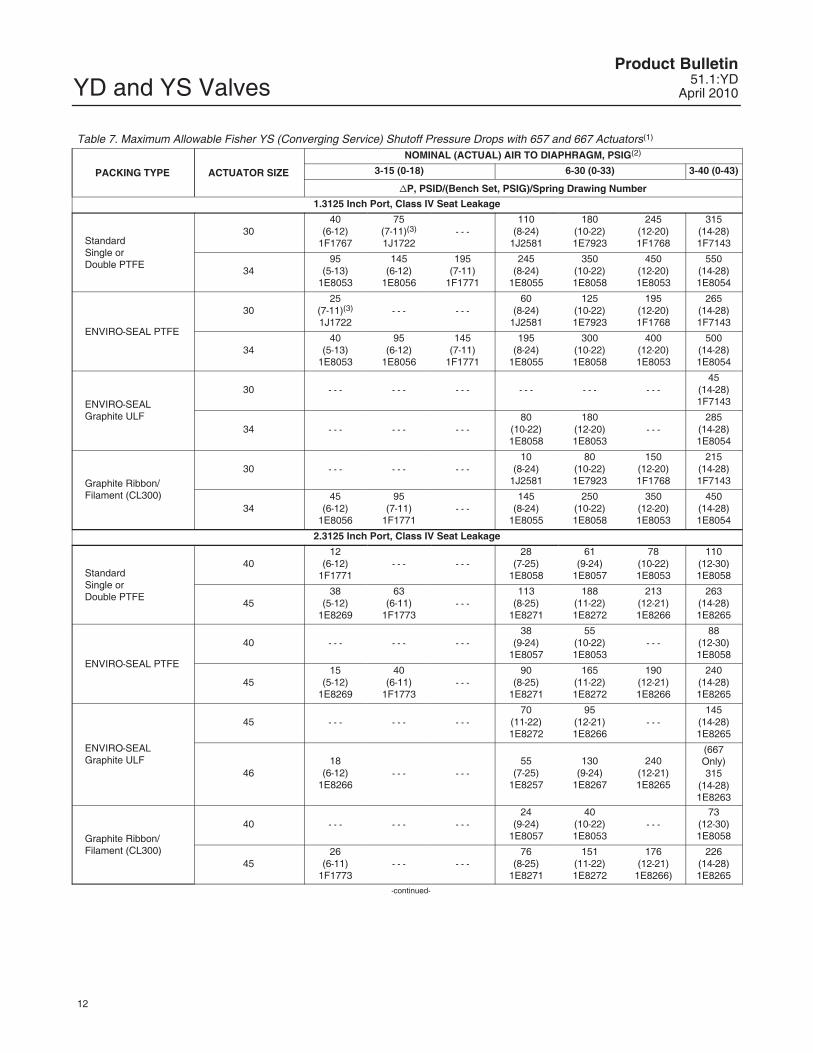
Table 7. Maximum Allowable Fisher YS (Converging Service) Shutoff Pressure Drops with 657 and 667 Actuators(1)
PACKING TYPE ACTUATOR SIZE
NOMINAL (ACTUAL) AIR TO DIAPHRAGM, PSIG(2)
3-15 (0-18) 6-30 (0-33) 3-40 (0-43)
�P, PSID/(Bench Set, PSIG)/Spring Drawing Number
1.3125 Inch Port, Class IV Seat Leakage
StandardSingle orDouble PTFE
3040
(6-12)1F1767
75(7-11)(3)
1J1722- - -
110(8-24)
1J2581
180(10-22)1E7923
245(12-20)1F1768
315(14-28)1F7143
3495
(5-13)1E8053
145(6-12)
1E8056
195(7-11)
1F1771
245(8-24)
1E8055
350(10-22)1E8058
450(12-20)1E8053
550(14-28)1E8054
ENVIRO-SEAL PTFE
3025
(7-11)(3)
1J1722- - - - - -
60(8-24)
1J2581
125(10-22)1E7923
195(12-20)1F1768
265(14-28)1F7143
3440
(5-13)1E8053
95(6-12)
1E8056
145(7-11)
1F1771
195(8-24)
1E8055
300(10-22)1E8058
400(12-20)1E8053
500(14-28)1E8054
ENVIRO-SEAL Graphite ULF
30 - - - - - - - - - - - - - - - - - -45
(14-28)1F7143
34 - - - - - - - - -80
(10-22)1E8058
180(12-20)1E8053
- - -285
(14-28)1E8054
Graphite Ribbon/Filament (CL300)
30 - - - - - - - - -10
(8-24)1J2581
80(10-22)1E7923
150(12-20)1F1768
215(14-28)1F7143
3445
(6-12)1E8056
95(7-11)
1F1771- - -
145(8-24)
1E8055
250(10-22)1E8058
350(12-20)1E8053
450(14-28)1E8054
2.3125 Inch Port, Class IV Seat Leakage
StandardSingle orDouble PTFE
4012
(6-12)1F1771
- - - - - -28
(7-25)1E8058
61(9-24)
1E8057
78(10-22)1E8053
110(12-30)1E8058
4538
(5-12)1E8269
63(6-11)
1F1773- - -
113(8-25)
1E8271
188(11-22)1E8272
213(12-21)1E8266
263(14-28)1E8265
ENVIRO-SEAL PTFE
40 - - - - - - - - -38
(9-24)1E8057
55(10-22)1E8053
- - -88
(12-30)1E8058
4515
(5-12)1E8269
40(6-11)
1F1773- - -
90(8-25)
1E8271
165(11-22)1E8272
190(12-21)1E8266
240(14-28)1E8265
ENVIRO-SEAL Graphite ULF
45 - - - - - - - - -70
(11-22)1E8272
95(12-21)1E8266
- - -145
(14-28)1E8265
4618
(6-12)1E8266
- - - - - -55
(7-25)1E8257
130(9-24)
1E8267
240(12-21)1E8265
(667Only)315
(14-28)1E8263
Graphite Ribbon/Filament (CL300)
40 - - - - - - - - -24
(9-24)1E8057
40(10-22)1E8053
- - -73
(12-30)1E8058
4526
(6-11)1F1773
- - - - - -76
(8-25)1E8271
151(11-22)1E8272
176(12-21)
1E8266)
226(14-28)1E8265
-continued-
YD and YS ValvesProduct Bulletin51.1:YDApril 2010
13
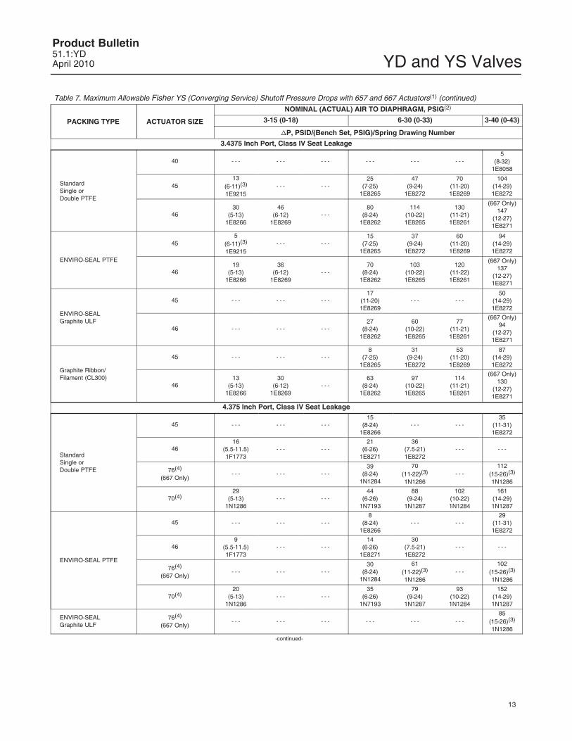
Table 7. Maximum Allowable Fisher YS (Converging Service) Shutoff Pressure Drops with 657 and 667 Actuators(1) (continued)
PACKING TYPE ACTUATOR SIZE
NOMINAL (ACTUAL) AIR TO DIAPHRAGM, PSIG(2)
3-15 (0-18) 6-30 (0-33) 3-40 (0-43)
�P, PSID/(Bench Set, PSIG)/Spring Drawing Number
3.4375 Inch Port, Class IV Seat Leakage
StandardSingle orDouble PTFE
40 - - - - - - - - - - - - - - - - - -5
(8-32)1E8058
4513
(6-11)(3)
1E9215- - - - - -
25(7-25)
1E8265
47(9-24)
1E8272
70(11-20)1E8269
104(14-29)1E8272
4630
(5-13)1E8266
46(6-12)
1E8269- - -
80(8-24)
1E8262
114(10-22)1E8265
130(11-21)1E8261
(667 Only)147
(12-27)1E8271
ENVIRO-SEAL PTFE
455
(6-11)(3)
1E9215- - - - - -
15(7-25)
1E8265
37(9-24)
1E8272
60(11-20)1E8269
94(14-29)1E8272
4619
(5-13)1E8266
36(6-12)
1E8269- - -
70(8-24)
1E8262
103(10-22)1E8265
120(11-22)1E8261
(667 Only)137
(12-27)1E8271
ENVIRO-SEAL Graphite ULF
45 - - - - - - - - -17
(11-20)1E8269
- - - - - -50
(14-29)1E8272
46 - - - - - - - - -27
(8-24)1E8262
60(10-22)1E8265
77(11-21)1E8261
(667 Only)94
(12-27)1E8271
Graphite Ribbon/Filament (CL300)
45 - - - - - - - - -8
(7-25)1E8265
31(9-24)
1E8272
53(11-20)1E8269
87(14-29)1E8272
4613
(5-13)1E8266
30(6-12)
1E8269- - -
63(8-24)
1E8262
97(10-22)1E8265
114(11-21)1E8261
(667 Only)130
(12-27)1E8271
4.375 Inch Port, Class IV Seat Leakage
StandardSingle orDouble PTFE
45 - - - - - - - - -15
(8-24)1E8266
- - - - - -35
(11-31)1E8272
4616
(5.5-11.5)1F1773
- - - - - -21
(6-26)1E8271
36(7.5-21)1E8272
- - - - - -
76(4)
(667 Only)- - - - - - - - -
39(8-24)
1N1284
70(11-22)(3)
1N1286- - -
112(15-26)(3)
1N1286
70(4)29
(5-13)1N1286
- - - - - -44
(6-26)1N7193
88(9-24)
1N1287
102(10-22)1N1284
161(14-29)1N1287
ENVIRO-SEAL PTFE
45 - - - - - - - - -8
(8-24)1E8266
- - - - - -29
(11-31)1E8272
469
(5.5-11.5)1F1773
- - - - - -14
(6-26)1E8271
30(7.5-21)1E8272
- - - - - -
76(4)
(667 Only)- - - - - - - - -
30(8-24)
1N1284
61(11-22)(3)
1N1286- - -
102(15-26)(3)
1N1286
70(4)20
(5-13)1N1286
- - - - - -35
(6-26)1N7193
79(9-24)
1N1287
93(10-22)1N1284
152(14-29)1N1287
ENVIRO-SEAL Graphite ULF
76(4)
(667 Only)- - - - - - - - - - - - - - - - - -
85(15-26)(3)
1N1286
-continued-
YD and YS ValvesProduct Bulletin
51.1:YDApril 2010
14
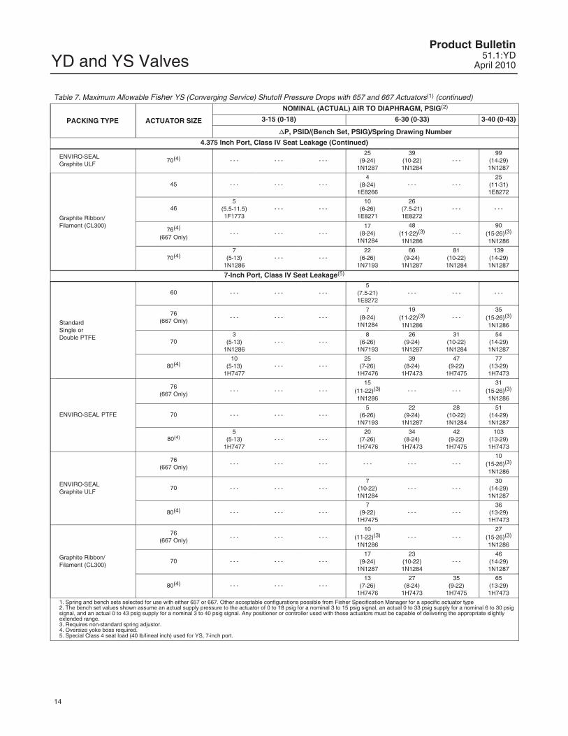
Table 7. Maximum Allowable Fisher YS (Converging Service) Shutoff Pressure Drops with 657 and 667 Actuators(1) (continued)
PACKING TYPE ACTUATOR SIZE
NOMINAL (ACTUAL) AIR TO DIAPHRAGM, PSIG(2)
3-15 (0-18) 6-30 (0-33) 3-40 (0-43)
�P, PSID/(Bench Set, PSIG)/Spring Drawing Number
4.375 Inch Port, Class IV Seat Leakage (Continued)
ENVIRO-SEAL Graphite ULF
70(4) - - - - - - - - -25
(9-24)1N1287
39(10-22)1N1284
- - -99
(14-29)1N1287
Graphite Ribbon/Filament (CL300)
45 - - - - - - - - -4
(8-24)1E8266
- - - - - -25
(11-31)1E8272
465
(5.5-11.5)1F1773
- - - - - -10
(6-26)1E8271
26(7.5-21)1E8272
- - - - - -
76(4)
(667 Only)- - - - - - - - -
17(8-24)
1N1284
48(11-22)(3)
1N1286- - -
90(15-26)(3)
1N1286
70(4)7
(5-13)1N1286
- - - - - -22
(6-26)1N7193
66(9-24)
1N1287
81(10-22)1N1284
139(14-29)1N1287
7-Inch Port, Class IV Seat Leakage(5)
StandardSingle orDouble PTFE
60 - - - - - - - - -5
(7.5-21)1E8272
- - - - - - - - -
76(667 Only)
- - - - - - - - -7
(8-24)1N1284
19(11-22)(3)
1N1286- - -
35(15-26)(3)
1N1286
703
(5-13)1N1286
- - - - - -8
(6-26)1N7193
26(9-24)
1N1287
31(10-22)1N1284
54(14-29)1N1287
80(4)10
(5-13)1H7477
- - - - - -25
(7-26)1H7476
39(8-24)
1H7473
47(9-22)
1H7475
77(13-29)1H7473
ENVIRO-SEAL PTFE
76(667 Only)
- - - - - - - - -15
(11-22)(3)
1N1286- - - - - -
31(15-26)(3)
1N1286
70 - - - - - - - - -5
(6-26)1N7193
22(9-24)
1N1287
28(10-22)1N1284
51(14-29)1N1287
80(4)5
(5-13)1H7477
- - - - - -20
(7-26)1H7476
34(8-24)
1H7473
42(9-22)
1H7475
103(13-29)1H7473
ENVIRO-SEAL Graphite ULF
76(667 Only)
- - - - - - - - - - - - - - - - - -10
(15-26)(3)
1N1286
70 - - - - - - - - -7
(10-22)1N1284
- - - - - -30
(14-29)1N1287
80(4) - - - - - - - - -7
(9-22)1H7475
- - - - - -36
(13-29)1H7473
Graphite Ribbon/Filament (CL300)
76(667 Only)
- - - - - - - - -10
(11-22)(3)
1N1286- - - - - -
27(15-26)(3)
1N1286
70 - - - - - - - - -17
(9-24)1N1287
23(10-22)1N1284
- - -46
(14-29)1N1287
80(4) - - - - - - - - -13
(7-26)1H7476
27(8-24)
1H7473
35(9-22)
1H7475
65(13-29)1H7473
1. Spring and bench sets selected for use with either 657 or 667. Other acceptable configurations possible from Fisher Specification Manager for a specific actuator type2. The bench set values shown assume an actual supply pressure to the actuator of 0 to 18 psig for a nominal 3 to 15 psig signal, an actual 0 to 33 psig supply for a nominal 6 to 30 psigsignal, and an actual 0 to 43 psig supply for a nominal 3 to 40 psig signal. Any positioner or controller used with these actuators must be capable of delivering the appropriate slightlyextended range.3. Requires non-standard spring adjustor.4. Oversize yoke boss required.5. Special Class 4 seat load (40 lb/lineal inch) used for YS, 7-inch port.
YD and YS ValvesProduct Bulletin51.1:YDApril 2010
15
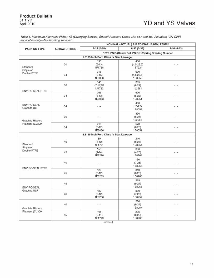
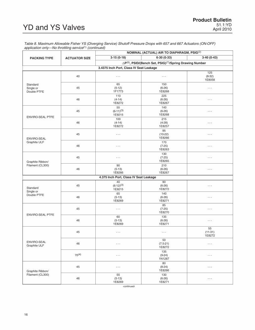
Table 8. Maximum Allowable Fisher YS (Diverging Service) Shutoff Pressure Drops with 657 and 667 Actuators (ON-OFF)application only—No throttling service(1)
PACKING TYPE ACTUATOR SIZE
NOMINAL (ACTUAL) AIR TO DIAPHRAGM, PSIG(2)
3-15 (0-18) 6-30 (0-33) 3-40 (0-43)
�P(6), PSID/(Bench Set, PSIG)(7)/Spring Drawing Number
1.3125 Inch Port, Class IV Seat Leakage
StandardSingle orDouble PTFE
30195
(5-13)1F1768
450(4.5-28.5)1E7924
- - -
34315
(3-15)1E8058
600(4.5-28.5)1E8052
- - -
ENVIRO-SEAL PTFE
30145
(7-11)(3)
1J1722
385(8-24)
1J2581- - -
34265
(5-13)1E8053
600(6-26)
1E8051- - -
ENVIRO-SEAL Graphite ULF
34 - - -400
(10-22)1E8058
- - -
Graphite Ribbon/Filament (CL300)
30 - - -330
(8-24)1J2581
- - -
34210
(6-12)1E8056
570(6-26)
1E8051- - -
2.3125 Inch Port, Class IV Seat Leakage
StandardSingle orDouble PTFE
4050
(6-12)1F1771
210(6-26)
1E8054- - -
45155
(4-14)1E8270
330(4-28)
1E8264- - -
ENVIRO-SEAL PTFE
40 - - -190
(7-25)1E8058
- - -
45120
(5-12)1E8269
310(6-26)
1E8263- - -
ENVIRO-SEAL Graphite ULF
45 - - -225
(9-24)1E8268
- - -
46120
(6-12)1E8266
380(7-25)
1E8257- - -
Graphite Ribbon/Filament (CL300)
40 - - -280
(9-24)1E8057
- - -
45105
(6-11)1F1773
295(6-26)
1E8263- - -
-continued-
YD and YS ValvesProduct Bulletin
51.1:YDApril 2010
16
Table 8. Maximum Allowable Fisher YS (Diverging Service) Shutoff Pressure Drops with 657 and 667 Actuators (ON-OFF)application only—No throttling service(1) (continued)
PACKING TYPE ACTUATOR SIZE
NOMINAL (ACTUAL) AIR TO DIAPHRAGM, PSIG(2)
3-15 (0-18) 6-30 (0-33) 3-40 (0-43)
�P(6), PSID/(Bench Set, PSIG)(7)/Spring Drawing Number
3.4375 Inch Port, Class IV Seat Leakage
StandardSingle orDouble PTFE
40 - - - - - -125
(8-32)1E8058
4565
(5-12)1F1773
150(6-26)
1E8268- - -
46110
(4-14)1E8272
225(6-26)
1E8267- - -
ENVIRO-SEAL PTFE
4555
(6-11)(3)
1E9215
140(6-26)
1E8268- - -
46100
(4-14)1E8272
215(4-28)
1E8257- - -
ENVIRO-SEAL Graphite ULF
45 - - -95
(10-22)1E8266
- - -
46 - - -170
(7-25)1E8263
- - -
Graphite Ribbon/Filament (CL300)
45 - - -130
(7-25)1E8265
- - -
4690
(5-13)1E8266
210(6-26)
1E8267- - -
4.375 Inch Port, Class IV Seat Leakage
StandardSingle orDouble PTFE
4540
(6-12)(3)
1E9215
90(6-26)
1E8272- - -
4665
(5-13)1E8269
140(6-26)
1E8271- - -
ENVIRO-SEAL PTFE
45 - - -85
(7-25)1E8270
- - -
4660
(5-13)1E8269
135(6-26)
1E8271- - -
ENVIRO-SEAL Graphite ULF
45 - - - - - -55
(11-31)1E8272
46 - - -50
(7.5-21)1E8272
- - -
70(4) - - -135
(9-24)1N1287
- - -
Graphite Ribbon/Filament (CL300)
45 - - -80
(8-24)1E8266
- - -
4655
(5-13)1E8269
130(6-26)
1E8271- - -
-continued-
YD and YS ValvesProduct Bulletin51.1:YDApril 2010
17
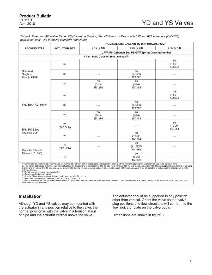
Table 8. Maximum Allowable Fisher YS (Diverging Service) Shutoff Pressure Drops with 657 and 667 Actuators (ON-OFF)application only—No throttling service(1) (continued)
PACKING TYPE ACTUATOR SIZE
NOMINAL (ACTUAL) AIR TO DIAPHRAGM, PSIG(2)
3-15 (0-18) 6-30 (0-33) 3-40 (0-43)
�P(6), PSID/(Bench Set, PSIG)(7)/Spring Drawing Number
7-Inch Port, Class IV Seat Leakage(5)
StandardSingle orDouble PTFE
50 - - - - - -50
(11-31)1E8272
60 - - -45
(7.5-21)1E8272
- - -
7035
(5-13)1N1286
75(6-26)
1N7193- - -
ENVIRO-SEAL PTFE
50 - - - - - -45
(11-31)1E8272
60 - - -40
(7.5-21)1E8272
- - -
7030
(5-13)1N1286
70(6-26)
1N7193- - -
ENVIRO-SEAL Graphite ULF
76(667 Only)
- - - - - -50
(13-29)1N1284
70 - - -50
(10-22)1N1284
- - -
Graphite Ribbon/Filament (CL300)
76(667 Only)
- - -45
(11-22)(3)
1N1286- - -
70 - - -70
(6-26)1N7193
- - -
1. Spring and bench sets selected for use with either 657 or 667. Other acceptable configurations possible from Fisher Specification Manager for a specific actuator type2. The bench set values shown assume an actual supply pressure to the actuator of 0 to 18 psig for a nominal 3 to 15 psig signal, an actual 0 to 33 psig supply for a nominal 6 to 30 psigsignal, and an actual 0 to 43 psig supply for a nominal 3 to 40 psig signal. Any positioner or controller used with these actuators must be capable of delivering the appropriate slightlyextended range.3. Requires non-standard spring adjustor.4. Oversize yoke boss required.5. Special Class 4 seat load (40 lb/lineal inch) used for YS, 7-inch port.6. Assumes same shutoff pressure drop for top and bottom ports.7. Bench sets selected will provide sufficient seat loading, even with no pressure drop. The selected bench sets will enable the actuator to fully stroke the valve up or down with themaximum shutoff drop listed.
Installation
Although YD and YS valves may be mounted withthe actuator in any position relative to the valve, thenormal position is with the valve in a horizontal runof pipe and the actuator vertical above the valve.
The actuator should be supported in any positionother than vertical. Orient the valve so that valveplug positions and flow directions will conform to theflow indicator plate on the valve body.
Dimensions are shown in figure 8.
YD and YS ValvesProduct Bulletin
51.1:YDApril 2010
18
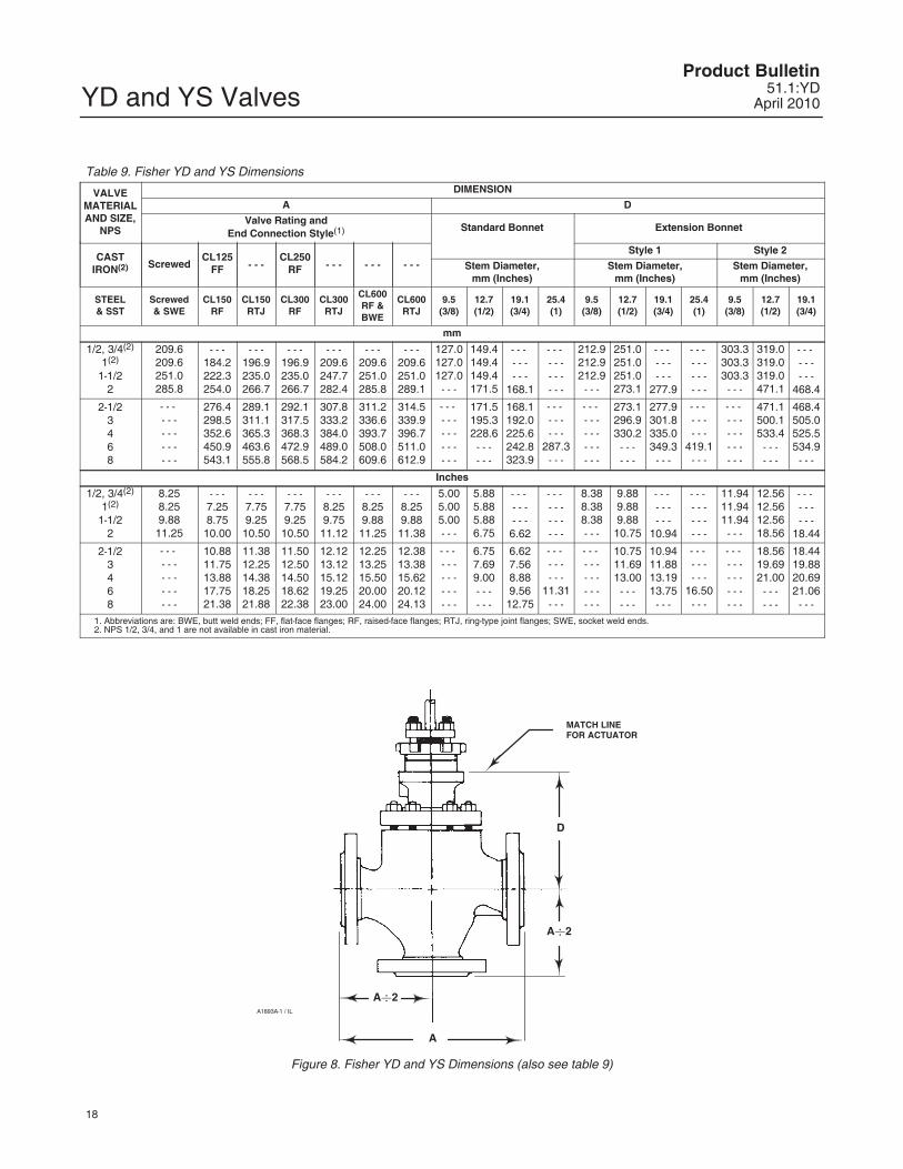
Table 9. Fisher YD and YS Dimensions
VALVEMATERIALAND SIZE,
NPS
DIMENSION
A D
Valve Rating andEnd Connection Style(1) Standard Bonnet Extension Bonnet
CASTIRON(2) Screwed
CL125FF - - -
CL250RF - - - - - - - - -
Style 1 Style 2
Stem Diameter,mm (Inches)
Stem Diameter,mm (Inches)
Stem Diameter,mm (Inches)
STEEL& SST
Screwed& SWE
CL150RF
CL150RTJ
CL300RF
CL300RTJ
CL600RF &BWE
CL600RTJ
9.5(3/8)
12.7(1/2)
19.1(3/4)
25.4(1)
9.5(3/8)
12.7(1/2)
19.1(3/4)
25.4(1)
9.5(3/8)
12.7(1/2)
19.1(3/4)
mm
1/2, 3/4(2)
1(2)
1-1/22
209.6209.6251.0285.8
- - -184.2222.3254.0
- - -196.9235.0266.7
- - -196.9235.0266.7
- - -209.6247.7282.4
- - -209.6251.0285.8
- - -209.6251.0289.1
127.0127.0127.0- - -
149.4149.4149.4171.5
- - - - - -- - -
168.1
- - - - - -- - -- - -
212.9212.9212.9- - -
251.0251.0251.0273.1
- - - - - -- - -
277.9
- - - - - -- - -- - -
303.3303.3303.3- - -
319.0319.0319.0471.1
- - - - - -- - -
468.4
2-1/23468
- - - - - -- - -- - -- - -
276.4298.5352.6450.9543.1
289.1311.1365.3463.6555.8
292.1317.5368.3472.9568.5
307.8333.2384.0489.0584.2
311.2336.6393.7508.0609.6
314.5339.9396.7511.0612.9
- - - - - -- - -- - -- - -
171.5195.3228.6- - -- - -
168.1192.0225.6242.8323.9
- - - - - -- - -
287.3- - -
- - - - - -- - -- - -- - -
273.1296.9330.2- - -- - -
277.9301.8335.0349.3- - -
- - - - - -- - -
419.1- - -
- - - - - -- - -- - -- - -
471.1500.1533.4- - -- - -
468.4505.0525.5534.9- - -
Inches
1/2, 3/4(2)
1(2)
1-1/22
8.258.259.88
11.25
- - -7.258.75
10.00
- - -7.759.25
10.50
- - -7.759.25
10.50
- - -8.259.75
11.12
- - -8.259.88
11.25
- - -8.259.88
11.38
5.005.005.00- - -
5.885.885.886.75
- - - - - -- - -
6.62
- - - - - -- - -- - -
8.388.388.38- - -
9.889.889.88
10.75
- - - - - -- - -
10.94
- - - - - -- - -- - -
11.9411.9411.94- - -
12.5612.5612.5618.56
- - - - - -- - -
18.44
2-1/23468
- - - - - -- - -- - -- - -
10.8811.7513.8817.7521.38
11.3812.2514.3818.2521.88
11.5012.5014.5018.6222.38
12.1213.1215.1219.2523.00
12.2513.2515.5020.0024.00
12.3813.3815.6220.1224.13
- - - - - -- - -- - -- - -
6.757.699.00- - -- - -
6.627.568.889.56
12.75
- - - - - -- - -
11.31- - -
- - - - - -- - -- - -- - -
10.7511.6913.00- - -- - -
10.9411.8813.1913.75- - -
- - - - - -- - -
16.50- - -
- - - - - -- - -- - -- - -
18.5619.6921.00- - -- - -
18.4419.8820.6921.06- - -
1. Abbreviations are: BWE, butt weld ends; FF, flat-face flanges; RF, raised-face flanges; RTJ, ring-type joint flanges; SWE, socket weld ends.2. NPS 1/2, 3/4, and 1 are not available in cast iron material.
D
A�2
A
MATCH LINEFOR ACTUATOR
A�2A1893A-1 / IL
Figure 8. Fisher YD and YS Dimensions (also see table 9)
YD and YS ValvesProduct Bulletin51.1:YDApril 2010
19
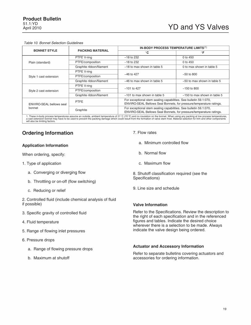
Table 10. Bonnet Selection Guidelines
BONNET STYLE PACKING MATERIALIN-BODY PROCESS TEMPERATURE LIMITS(1)
�C �F
Plain (standard)
PTFE V-ring �18 to 232 0 to 450
PTFE/composition �18 to 232 0 to 450
Graphite ribbon/filament �18 to max shown in table 5 0 to max shown in table 5
Style 1 cast extension
PTFE V-ring�46 to 427 �50 to 800
PTFE/composition
Graphite ribbon/filament �46 to max shown in table 5 �50 to max shown in table 5
Style 2 cast extension
PTFE V-ring�101 to 427 �150 to 800
PTFE/composition
Graphite ribbon/filament �101 to max shown in table 5 �150 to max shown in table 5
ENVIRO-SEAL bellows sealbonnet
PTFE For exceptional stem sealing capabilities. See bulletin 59.1:070,ENVIRO-SEAL Bellows Seal Bonnets, for pressure/temperature ratings.
Graphite For exceptional stem sealing capabilities. See bulletin 59.1:070,ENVIRO-SEAL Bellows Seal Bonnets, for pressure/temperature ratings.
1. These in-body process temperatures assume an outside, ambient temperature of 21�C (70�F) and no insulation on the bonnet. When using any packing at low process temperatures,a cast extension bonnet may have to be used to prevent the packing damage which could result from the formation of valve stem frost. Material selection for trim and other componentswill also be limiting factors.
Ordering Information
Application Information
When ordering, specify:
1. Type of application
a. Converging or diverging flow
b. Throttling or on-off (flow switching)
c. Reducing or relief
2. Controlled fluid (include chemical analysis of fluidif possible)
3. Specific gravity of controlled fluid
4. Fluid temperature
5. Range of flowing inlet pressures
6. Pressure drops
a. Range of flowing pressure drops
b. Maximum at shutoff
7. Flow rates
a. Minimum controlled flow
b. Normal flow
c. Maximum flow
8. Shutoff classification required (see theSpecifications)
9. Line size and schedule
Valve Information
Refer to the Specifications. Review the description tothe right of each specification and in the referencedfigures and tables. Indicate the desired choicewherever there is a selection to be made. Alwaysindicate the valve design being ordered.
Actuator and Accessory Information
Refer to separate bulletins covering actuators andaccessories for ordering information.
YD and YS ValvesProduct Bulletin
51.1:YDApril 2010
20
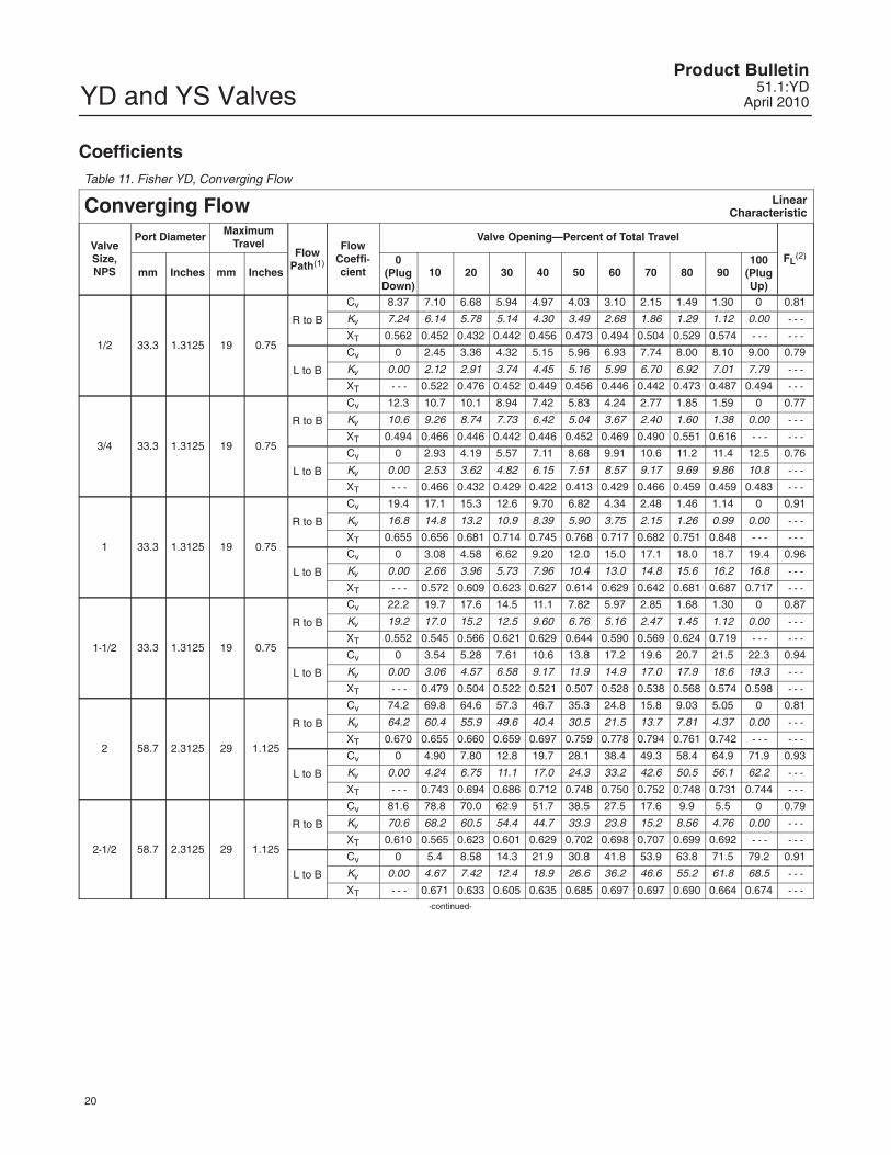
CoefficientsTable 11. Fisher YD, Converging Flow
Converging Flow LinearCharacteristic
ValveSize,NPS
Port Diameter MaximumTravel
FlowPath(1)
FlowCoeffi-cient
Valve Opening—Percent of Total Travel
FL(2)
mm Inches mm Inches0
(PlugDown)
10 20 30 40 50 60 70 80 90100
(PlugUp)
1/2 33.3 1.3125 19 0.75
R to B
Cv 8.37 7.10 6.68 5.94 4.97 4.03 3.10 2.15 1.49 1.30 0 0.81
Kv 7.24 6.14 5.78 5.14 4.30 3.49 2.68 1.86 1.29 1.12 0.00 - - -
XT 0.562 0.452 0.432 0.442 0.456 0.473 0.494 0.504 0.529 0.574 - - - - - -
L to B
Cv 0 2.45 3.36 4.32 5.15 5.96 6.93 7.74 8.00 8.10 9.00 0.79
Kv 0.00 2.12 2.91 3.74 4.45 5.16 5.99 6.70 6.92 7.01 7.79 - - -
XT - - - 0.522 0.476 0.452 0.449 0.456 0.446 0.442 0.473 0.487 0.494 - - -
3/4 33.3 1.3125 19 0.75
R to B
Cv 12.3 10.7 10.1 8.94 7.42 5.83 4.24 2.77 1.85 1.59 0 0.77
Kv 10.6 9.26 8.74 7.73 6.42 5.04 3.67 2.40 1.60 1.38 0.00 - - -
XT 0.494 0.466 0.446 0.442 0.446 0.452 0.469 0.490 0.551 0.616 - - - - - -
L to B
Cv 0 2.93 4.19 5.57 7.11 8.68 9.91 10.6 11.2 11.4 12.5 0.76
Kv 0.00 2.53 3.62 4.82 6.15 7.51 8.57 9.17 9.69 9.86 10.8 - - -
XT - - - 0.466 0.432 0.429 0.422 0.413 0.429 0.466 0.459 0.459 0.483 - - -
1 33.3 1.3125 19 0.75
R to B
Cv 19.4 17.1 15.3 12.6 9.70 6.82 4.34 2.48 1.46 1.14 0 0.91
Kv 16.8 14.8 13.2 10.9 8.39 5.90 3.75 2.15 1.26 0.99 0.00 - - -
XT 0.655 0.656 0.681 0.714 0.745 0.768 0.717 0.682 0.751 0.848 - - - - - -
L to B
Cv 0 3.08 4.58 6.62 9.20 12.0 15.0 17.1 18.0 18.7 19.4 0.96
Kv 0.00 2.66 3.96 5.73 7.96 10.4 13.0 14.8 15.6 16.2 16.8 - - -
XT - - - 0.572 0.609 0.623 0.627 0.614 0.629 0.642 0.681 0.687 0.717 - - -
1-1/2 33.3 1.3125 19 0.75
R to B
Cv 22.2 19.7 17.6 14.5 11.1 7.82 5.97 2.85 1.68 1.30 0 0.87
Kv 19.2 17.0 15.2 12.5 9.60 6.76 5.16 2.47 1.45 1.12 0.00 - - -
XT 0.552 0.545 0.566 0.621 0.629 0.644 0.590 0.569 0.624 0.719 - - - - - -
L to B
Cv 0 3.54 5.28 7.61 10.6 13.8 17.2 19.6 20.7 21.5 22.3 0.94
Kv 0.00 3.06 4.57 6.58 9.17 11.9 14.9 17.0 17.9 18.6 19.3 - - -
XT - - - 0.479 0.504 0.522 0.521 0.507 0.528 0.538 0.568 0.574 0.598 - - -
2 58.7 2.3125 29 1.125
R to B
Cv 74.2 69.8 64.6 57.3 46.7 35.3 24.8 15.8 9.03 5.05 0 0.81
Kv 64.2 60.4 55.9 49.6 40.4 30.5 21.5 13.7 7.81 4.37 0.00 - - -
XT 0.670 0.655 0.660 0.659 0.697 0.759 0.778 0.794 0.761 0.742 - - - - - -
L to B
Cv 0 4.90 7.80 12.8 19.7 28.1 38.4 49.3 58.4 64.9 71.9 0.93
Kv 0.00 4.24 6.75 11.1 17.0 24.3 33.2 42.6 50.5 56.1 62.2 - - -
XT - - - 0.743 0.694 0.686 0.712 0.748 0.750 0.752 0.748 0.731 0.744 - - -
2-1/2 58.7 2.3125 29 1.125
R to B
Cv 81.6 78.8 70.0 62.9 51.7 38.5 27.5 17.6 9.9 5.5 0 0.79
Kv 70.6 68.2 60.5 54.4 44.7 33.3 23.8 15.2 8.56 4.76 0.00 - - -
XT 0.610 0.565 0.623 0.601 0.629 0.702 0.698 0.707 0.699 0.692 - - - - - -
L to B
Cv 0 5.4 8.58 14.3 21.9 30.8 41.8 53.9 63.8 71.5 79.2 0.91
Kv 0.00 4.67 7.42 12.4 18.9 26.6 36.2 46.6 55.2 61.8 68.5 - - -
XT - - - 0.671 0.633 0.605 0.635 0.685 0.697 0.697 0.690 0.664 0.674 - - --continued-

YD and YS ValvesProduct Bulletin51.1:YDApril 2010
21
Table 11. Fisher YD, Converging Flow (continued)
ValveSize,NPS
Port Diameter MaximumTravel
FlowPath(1)
FlowCoeffi-cient
Valve Opening—Percent of Total Travel
FL(2)
mm Inches mm Inches0
(PlugDown)
10 20 30 40 50 60 70 80 90100
(PlugUp)
3 87.3 3.4375 38 1.5
R to B
Cv 143 133 121 107 91.1 73.7 56.6 39.0 20.9 8.64 0 0.74
Kv 124 115 105 93 78.8 63.8 49.0 33.7 18.1 7.47 0.00 - - -
XT 0.594 0.632 0.680 0.696 0.714 0.754 0.734 0.673 0.711 0.873 - - - - - -
L to B
Cv 0 18.7 33.9 51.7 70.1 87.9 101 120 134 146 156 0.92
Kv 0.00 16.2 29.3 44.7 60.6 76.0 87.4 104 116 126 135 - - -
XT - - - 0.848 0.757 0.692 0.644 0.621 0.643 0.670 0.743 0.744 0.730 - - -
4 111.1 4.375 51 2
R to B
Cv 248 236 222 200 175 147 117 86.9 56.6 29.0 0 0.74
Kv 215 204 192 173 151 127 101 75.2 49.0 25.1 0.00 - - -
XT 0.570 0.583 0.616 0.652 0.672 0.669 0.659 0.608 0.618 0.640 - - - - - -
L to B
Cv 0 10.2 26.5 49.7 78.4 113 154 189 216 241 265 0.92
Kv 0.00 8.82 22.9 43.0 67.8 97.7 133 163 187 208 229 - - -
XT - - - 0.658 0.622 0.616 0.625 0.631 0.643 0.683 0.704 0.711 0.752 - - -
6 177.8 7 51 2
R to B
Cv 451 424 387 338 282 223 162 108 60.1 22.9 0 0.84
Kv 390 367 335 292 244 193 140 93.4 52.0 19.8 0.00 - - -
XT 0.757 0.721 0.727 0.749 0.750 0.747 0.776 0.770 0.749 0.774 - - - - - -
L to B
Cv 0 49.4 102 161 221 284 337 387 433 474 506 0.91
Kv 0.00 42.7 88.2 139 191 246 292 335 375 410 438 - - -
XT - - - 0.592 0.623 0.662 0.695 0.688 0.728 0.749 0.740 0.757 0.773 - - -
8High
Capacity177.8 7 57.2 2.25
R to B
Cv 491 473 425 384 332 256 171 102 55 24 0 0.84
Kv 425 409 368 332 287 221 148 88.2 47.6 20.8 0.00 - - -
XT 0.702 0.669 0.662 0.689 0.609 0.653 0.710 0.613 0.558 0.349 0 - - -
L to B
Cv 0 10 34 62 103 170 264 361 446 527 588 0.91
Kv 0.00 8.65 29.4 53.6 89.1 147 228 312 386 456 509 - - -
XT 0 0.731 0.891 0.838 0.861 0.900 0.850 0.712 0.654 0.629 0.735 - - -
8Low
Capacity177.8 7 57.2 2.25
R to B
Cv 476 410 358 310 246 169 105 57.5 30.1 11.0 0 0.84
Kv 412 355 310 268 213 146 91 49.7 26.0 9.52 0 - - -
XT 0.668 0.669 0.668 0.668 0.668 0.668 0.669 0.669 0.669 0.666 0 - - -
L to B
Cv 0 12 25 47.9 88.1 144 213 283 376 461 542 0.91
Kv 0 10.4 21.6 41.4 76.2 125 184 245 325 399 469 - - -
XT 0 0.655 0.603 0.607 0.608 0.608 0.608 0.608 0.608 0.608 0.608 - - -1. The end connections are identified on the valve body.2. At maximum flow.
YD and YS ValvesProduct Bulletin
51.1:YDApril 2010
22
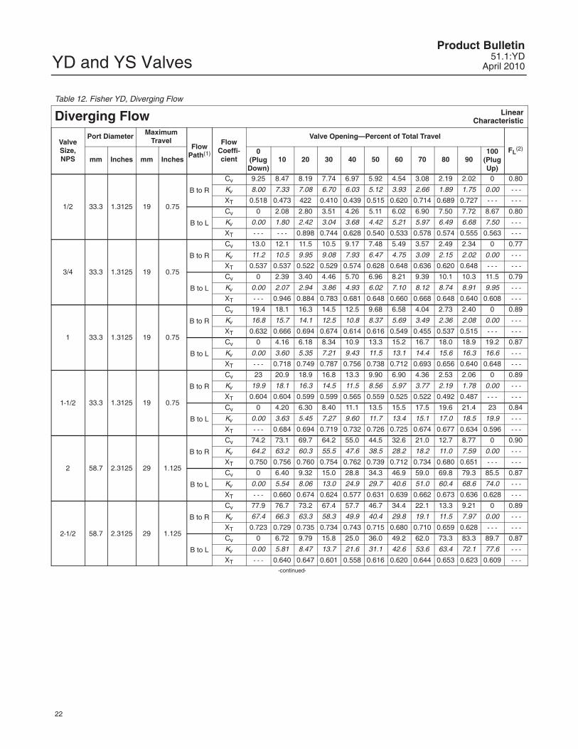
Table 12. Fisher YD, Diverging Flow
Diverging Flow LinearCharacteristic
ValveSize,NPS
Port Diameter MaximumTravel
FlowPath(1)
FlowCoeffi-cient
Valve Opening—Percent of Total Travel
FL(2)
mm Inches mm Inches0
(PlugDown)
10 20 30 40 50 60 70 80 90100
(PlugUp)
1/2 33.3 1.3125 19 0.75
B to R
Cv 9.25 8.47 8.19 7.74 6.97 5.92 4.54 3.08 2.19 2.02 0 0.80
Kv 8.00 7.33 7.08 6.70 6.03 5.12 3.93 2.66 1.89 1.75 0.00 - - -
XT 0.518 0.473 422 0.410 0.439 0.515 0.620 0.714 0.689 0.727 - - - - - -
B to L
Cv 0 2.08 2.80 3.51 4.26 5.11 6.02 6.90 7.50 7.72 8.67 0.80
Kv 0.00 1.80 2.42 3.04 3.68 4.42 5.21 5.97 6.49 6.68 7.50 - - -
XT - - - - - - 0.898 0.744 0.628 0.540 0.533 0.578 0.574 0.555 0.563 - - -
3/4 33.3 1.3125 19 0.75
B to R
Cv 13.0 12.1 11.5 10.5 9.17 7.48 5.49 3.57 2.49 2.34 0 0.77
Kv 11.2 10.5 9.95 9.08 7.93 6.47 4.75 3.09 2.15 2.02 0.00 - - -
XT 0.537 0.537 0.522 0.529 0.574 0.628 0.648 0.636 0.620 0.648 - - - - - -
B to L
Cv 0 2.39 3.40 4.46 5.70 6.96 8.21 9.39 10.1 10.3 11.5 0.79
Kv 0.00 2.07 2.94 3.86 4.93 6.02 7.10 8.12 8.74 8.91 9.95 - - -
XT - - - 0.946 0.884 0.783 0.681 0.648 0.660 0.668 0.648 0.640 0.608 - - -
1 33.3 1.3125 19 0.75
B to R
Cv 19.4 18.1 16.3 14.5 12.5 9.68 6.58 4.04 2.73 2.40 0 0.89
Kv 16.8 15.7 14.1 12.5 10.8 8.37 5.69 3.49 2.36 2.08 0.00 - - -
XT 0.632 0.666 0.694 0.674 0.614 0.616 0.549 0.455 0.537 0.515 - - - - - -
B to L
Cv 0 4.16 6.18 8.34 10.9 13.3 15.2 16.7 18.0 18.9 19.2 0.87
Kv 0.00 3.60 5.35 7.21 9.43 11.5 13.1 14.4 15.6 16.3 16.6 - - -
XT - - - 0.718 0.749 0.787 0.756 0.738 0.712 0.693 0.656 0.640 0.648 - - -
1-1/2 33.3 1.3125 19 0.75
B to R
Cv 23 20.9 18.9 16.8 13.3 9.90 6.90 4.36 2.53 2.06 0 0.89
Kv 19.9 18.1 16.3 14.5 11.5 8.56 5.97 3.77 2.19 1.78 0.00 - - -
XT 0.604 0.604 0.599 0.599 0.565 0.559 0.525 0.522 0.492 0.487 - - - - - -
B to L
Cv 0 4.20 6.30 8.40 11.1 13.5 15.5 17.5 19.6 21.4 23 0.84
Kv 0.00 3.63 5.45 7.27 9.60 11.7 13.4 15.1 17.0 18.5 19.9 - - -
XT - - - 0.684 0.694 0.719 0.732 0.726 0.725 0.674 0.677 0.634 0.596 - - -
2 58.7 2.3125 29 1.125
B to R
Cv 74.2 73.1 69.7 64.2 55.0 44.5 32.6 21.0 12.7 8.77 0 0.90
Kv 64.2 63.2 60.3 55.5 47.6 38.5 28.2 18.2 11.0 7.59 0.00 - - -
XT 0.750 0.756 0.760 0.754 0.762 0.739 0.712 0.734 0.680 0.651 - - - - - -
B to L
Cv 0 6.40 9.32 15.0 28.8 34.3 46.9 59.0 69.8 79.3 85.5 0.87
Kv 0.00 5.54 8.06 13.0 24.9 29.7 40.6 51.0 60.4 68.6 74.0 - - -
XT - - - 0.660 0.674 0.624 0.577 0.631 0.639 0.662 0.673 0.636 0.628 - - -
2-1/2 58.7 2.3125 29 1.125
B to R
Cv 77.9 76.7 73.2 67.4 57.7 46.7 34.4 22.1 13.3 9.21 0 0.89
Kv 67.4 66.3 63.3 58.3 49.9 40.4 29.8 19.1 11.5 7.97 0.00 - - -
XT 0.723 0.729 0.735 0.734 0.743 0.715 0.680 0.710 0.659 0.628 - - - - - -
B to L
Cv 0 6.72 9.79 15.8 25.0 36.0 49.2 62.0 73.3 83.3 89.7 0.87
Kv 0.00 5.81 8.47 13.7 21.6 31.1 42.6 53.6 63.4 72.1 77.6 - - -
XT - - - 0.640 0.647 0.601 0.558 0.616 0.620 0.644 0.653 0.623 0.609 - - --continued-
YD and YS ValvesProduct Bulletin51.1:YDApril 2010
23
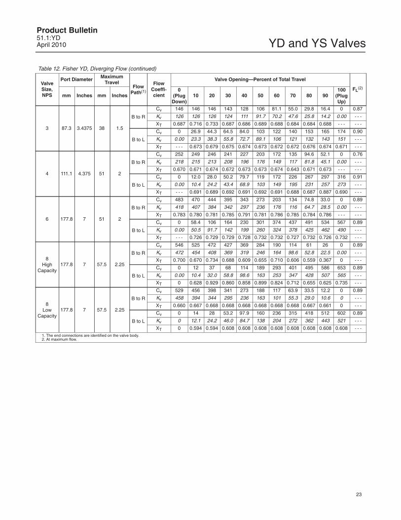
Table 12. Fisher YD, Diverging Flow (continued)
ValveSize,NPS
Port Diameter MaximumTravel
FlowPath(1)
FlowCoeffi-cient
Valve Opening—Percent of Total Travel
FL(2)
mm Inches mm Inches0
(PlugDown)
10 20 30 40 50 60 70 80 90100
(PlugUp)
3 87.3 3.4375 38 1.5
B to R
Cv 146 146 146 143 128 106 81.1 55.0 29.8 16.4 0 0.87
Kv 126 126 126 124 111 91.7 70.2 47.6 25.8 14.2 0.00 - - -
XT 0.687 0.716 0.733 0.687 0.686 0.689 0.688 0.684 0.684 0.688 - - - - - -
B to L
Cv 0 26.9 44.3 64.5 84.0 103 122 140 153 165 174 0.90
Kv 0.00 23.3 38.3 55.8 72.7 89.1 106 121 132 143 151 - - -
XT - - - 0.673 0.679 0.675 0.674 0.673 0.672 0.672 0.676 0.674 0.671 - - -
4 111.1 4.375 51 2
B to R
Cv 252 249 246 241 227 203 172 135 94.6 52.1 0 0.76
Kv 218 215 213 208 196 176 149 117 81.8 45.1 0.00 - - -
XT 0.670 0.671 0.674 0.672 0.673 0.673 0.674 0.643 0.671 0.673 - - - - - -
B to L
Cv 0 12.0 28.0 50.2 79.7 119 172 226 267 297 316 0.91
Kv 0.00 10.4 24.2 43.4 68.9 103 149 195 231 257 273 - - -
XT - - - 0.691 0.689 0.692 0.691 0.692 0.691 0.688 0.687 0.887 0.690 - - -
6 177.8 7 51 2
B to R
Cv 483 470 444 395 343 273 203 134 74.8 33.0 0 0.89
Kv 418 407 384 342 297 236 176 116 64.7 28.5 0.00 - - -
XT 0.783 0.780 0.781 0.785 0.791 0.781 0.786 0.785 0.784 0.786 - - - - - -
B to L
Cv 0 58.4 106 164 230 301 374 437 491 534 567 0.89
Kv 0.00 50.5 91.7 142 199 260 324 378 425 462 490 - - -
XT - - - 0.726 0.729 0.729 0.728 0.732 0.732 0.727 0.732 0.726 0.732 - - -
8High
Capacity177.8 7 57.5 2.25
B to R
Cv 546 525 472 427 369 284 190 114 61 26 0 0.89
Kv 472 454 408 369 319 246 164 98.6 52.8 22.5 0.00 - - -
XT 0.700 0.670 0.734 0.688 0.609 0.655 0.710 0.606 0.559 0.367 0 - - -
B to L
Cv 0 12 37 68 114 189 293 401 495 586 653 0.89
Kv 0.00 10.4 32.0 58.8 98.6 163 253 347 428 507 565 - - -
XT 0 0.628 0.929 0.860 0.858 0.899 0.824 0.712 0.655 0.625 0.735 - - -
8Low
Capacity177.8 7 57.5 2.25
B to R
Cv 529 456 398 341 273 188 117 63.9 33.5 12.2 0 0.89
Kv 458 394 344 295 236 163 101 55.3 29.0 10.6 0 - - -
XT 0.660 0.667 0.668 0.668 0.668 0.668 0.668 0.668 0.667 0.661 0 - - -
B to L
Cv 0 14 28 53.2 97.9 160 236 315 418 512 602 0.89
Kv 0 12.1 24.2 46.0 84.7 138 204 272 362 443 521 - - -
XT 0 0.594 0.594 0.608 0.608 0.608 0.608 0.608 0.608 0.608 0.608 - - -1. The end connections are identified on the valve body.2. At maximum flow.
YD and YS ValvesProduct Bulletin
51.1:YDApril 2010
24
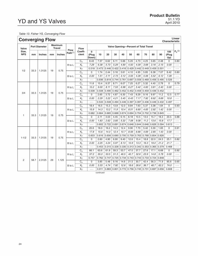
Table 13. Fisher YS, Converging Flow
Converging Flow LinearCharacteristic
ValveSize,NPS
Port Diameter MaximumTravel
FlowPath(1)
FlowCoeffi-cient
Valve Opening—Percent of Total Travel
FL(2)
mm Inches mm Inches0
(PlugDown)
10 20 30 40 50 60 70 80 90100
(PlugUp)
1/2 33.3 1.3125 19 0.75
R to L
Cv 8.43 7.37 6.62 6.11 5.66 5.20 4.73 4.25 3.65 2.48 0 0.80
Kv 7.29 6.38 5.73 5.29 4.90 4.50 4.09 3.68 3.16 2.15 0.00 - - -
XT 0.518 0.473 0.446 0.422 0.416 0.429 0.442 0.449 0.459 0.501 - - - - - -
B to L
Cv 0 1.74 2.44 3.16 3.61 4.10 4.95 5.85 6.38 7.07 8.42 0.80
Kv 0.00 1.51 2.11 2.73 3.12 3.55 4.28 5.06 5.52 6.12 7.28 - - -
XT - - - 0.936 0.819 0.744 0.761 0.697 0.559 0.469 0.456 0.490 0.526 - - -
3/4 33.3 1.3125 19 0.75
R to L
Cv 11.8 10.4 9.37 8.71 8.07 7.25 6.27 5.32 4.40 2.78 0 0.79
Kv 10.2 9.00 8.11 7.53 6.98 6.27 5.42 4.60 3.81 2.40 0.00 - - -
XT 0.508 0.508 0.490 0.462 0.452 0.452 0.459 0.459 0.436 0.452 - - - - - -
B to L
Cv 0 2.65 3.72 4.87 6.30 7.43 8.29 9.16 9.97 11.2 12.5 0.77
Kv 0.00 2.29 3.22 4.21 5.45 6.43 7.17 7.92 8.62 9.69 10.8 - - -
XT - - - 0.533 0.508 0.494 0.446 0.397 0.397 0.436 0.446 0.432 0.497 - - -
1 33.3 1.3125 19 0.75
R to L
Cv 18.4 16.5 15.3 13.8 12.0 9.84 7.63 5.37 3.38 1.64 0 0.93
Kv 15.9 14.3 13.2 11.9 10.4 8.51 6.60 4.65 2.92 1.42 0.00 - - -
XT 0.682 0.664 0.665 0.668 0.674 0.694 0.704 0.702 0.736 0.845 - - - - - -
B to L
Cv 0 2.11 3.03 4.45 6.15 8.18 10.5 13.0 15.7 18.3 20.5 0.88
Kv 0.00 1.83 2.62 3.85 5.32 7.08 9.08 11.2 13.6 15.8 17.7 - - -
XT - - - 0.602 0.722 0.691 0.674 0.646 0.644 0.646 0.626 0.594 0.613 - - -
1-1/2 33.3 1.3125 19 0.75
R to L
Cv 20.6 18.0 16.2 14.3 12.4 9.90 7.70 5.42 3.30 1.65 0 0.91
Kv 17.8 15.6 14.0 12.4 10.7 8.56 6.66 4.69 2.85 1.43 0.00 - - -
XT 0.603 0.616 0.656 0.690 0.700 0.759 0.763 0.768 0.854 0.926 - - - - - -
B to L
Cv 0 2.60 4.90 6.90 9.40 12.6 15.4 18.8 22.0 24.5 25.1 0.82
Kv 0.00 2.25 4.24 5.97 8.13 10.9 13.3 16.3 19.0 21.2 21.7 - - -
XT - - - 0.453 0.315 0.328 0.330 0.313 0.342 0.353 0.365 0.379 0.468 - - -
2 58.7 2.3125 29 1.125
R to L
Cv 66.1 63.6 61.9 59.3 53.7 47.0 37.7 27.6 17.1 6.68 0 0.92
Kv 57.2 55.0 53.5 51.3 46.5 40.7 32.6 23.9 14.8 5.78 0.00 - - -
XT 0.757 0.762 0.747 0.725 0.734 0.743 0.743 0.733 0.724 0.848 - - - - - -
B to L
Cv 0 3.85 5.48 9.16 14.6 21.5 30.7 42.4 56.3 71.9 85.6 0.65
Kv 0.00 3.33 4.74 7.92 12.6 18.6 26.6 36.7 48.7 62.2 74.0 - - -
XT - - - 0.911 0.883 0.801 0.772 0.756 0.745 0.731 0.697 0.656 0.608 - - --continued-
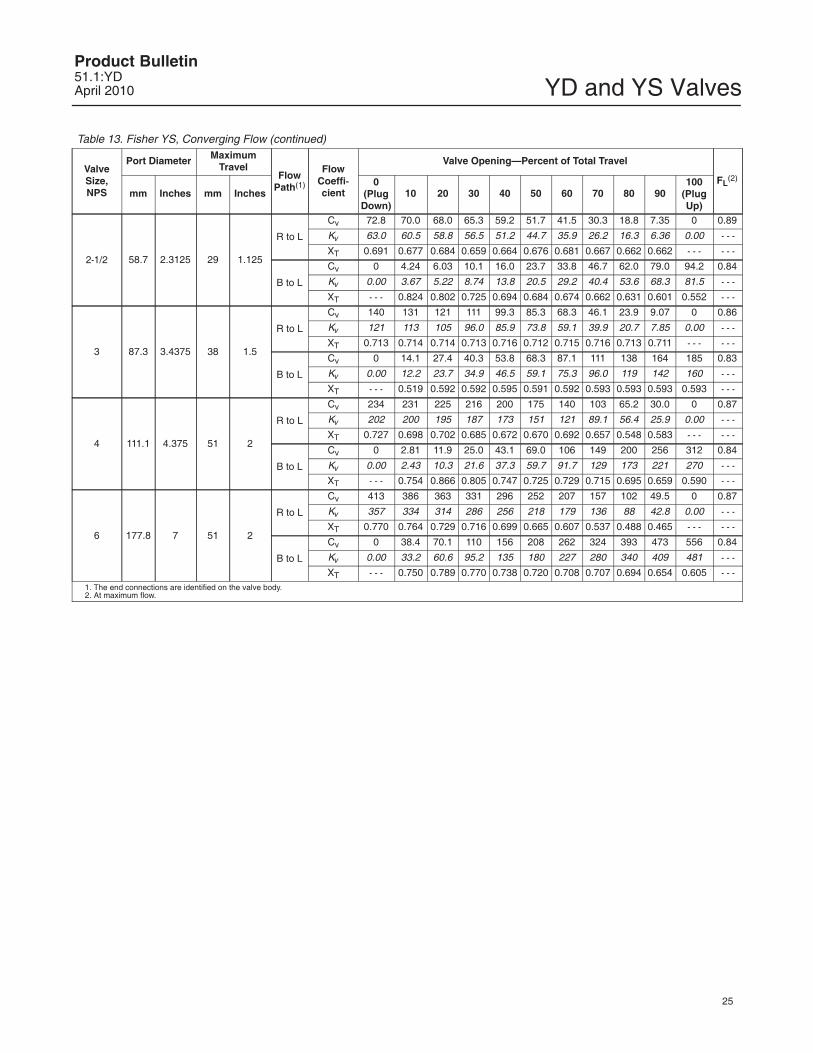
YD and YS ValvesProduct Bulletin51.1:YDApril 2010
25
Table 13. Fisher YS, Converging Flow (continued)
ValveSize,NPS
Port Diameter MaximumTravel
FlowPath(1)
FlowCoeffi-cient
Valve Opening—Percent of Total Travel
FL(2)
mm Inches mm Inches0
(PlugDown)
10 20 30 40 50 60 70 80 90100
(PlugUp)
2-1/2 58.7 2.3125 29 1.125
R to L
Cv 72.8 70.0 68.0 65.3 59.2 51.7 41.5 30.3 18.8 7.35 0 0.89
Kv 63.0 60.5 58.8 56.5 51.2 44.7 35.9 26.2 16.3 6.36 0.00 - - -
XT 0.691 0.677 0.684 0.659 0.664 0.676 0.681 0.667 0.662 0.662 - - - - - -
B to L
Cv 0 4.24 6.03 10.1 16.0 23.7 33.8 46.7 62.0 79.0 94.2 0.84
Kv 0.00 3.67 5.22 8.74 13.8 20.5 29.2 40.4 53.6 68.3 81.5 - - -
XT - - - 0.824 0.802 0.725 0.694 0.684 0.674 0.662 0.631 0.601 0.552 - - -
3 87.3 3.4375 38 1.5
R to L
Cv 140 131 121 111 99.3 85.3 68.3 46.1 23.9 9.07 0 0.86
Kv 121 113 105 96.0 85.9 73.8 59.1 39.9 20.7 7.85 0.00 - - -
XT 0.713 0.714 0.714 0.713 0.716 0.712 0.715 0.716 0.713 0.711 - - - - - -
B to L
Cv 0 14.1 27.4 40.3 53.8 68.3 87.1 111 138 164 185 0.83
Kv 0.00 12.2 23.7 34.9 46.5 59.1 75.3 96.0 119 142 160 - - -
XT - - - 0.519 0.592 0.592 0.595 0.591 0.592 0.593 0.593 0.593 0.593 - - -
4 111.1 4.375 51 2
R to L
Cv 234 231 225 216 200 175 140 103 65.2 30.0 0 0.87
Kv 202 200 195 187 173 151 121 89.1 56.4 25.9 0.00 - - -
XT 0.727 0.698 0.702 0.685 0.672 0.670 0.692 0.657 0.548 0.583 - - - - - -
B to L
Cv 0 2.81 11.9 25.0 43.1 69.0 106 149 200 256 312 0.84
Kv 0.00 2.43 10.3 21.6 37.3 59.7 91.7 129 173 221 270 - - -
XT - - - 0.754 0.866 0.805 0.747 0.725 0.729 0.715 0.695 0.659 0.590 - - -
6 177.8 7 51 2
R to L
Cv 413 386 363 331 296 252 207 157 102 49.5 0 0.87
Kv 357 334 314 286 256 218 179 136 88 42.8 0.00 - - -
XT 0.770 0.764 0.729 0.716 0.699 0.665 0.607 0.537 0.488 0.465 - - - - - -
B to L
Cv 0 38.4 70.1 110 156 208 262 324 393 473 556 0.84
Kv 0.00 33.2 60.6 95.2 135 180 227 280 340 409 481 - - -
XT - - - 0.750 0.789 0.770 0.738 0.720 0.708 0.707 0.694 0.654 0.605 - - -1. The end connections are identified on the valve body.2. At maximum flow.
YD and YS ValvesProduct Bulletin
51.1:YDApril 2010
26
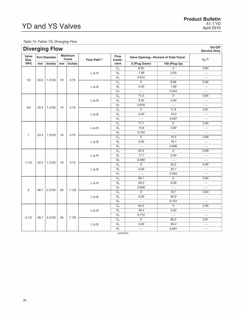
Table 14. Fisher YS, Diverging Flow
Diverging Flow On-OffService Only
ValveSize,NPS
Port Diameter MaximumTravel Flow Path(1)
FlowCoeffi-cient
Valve Opening—Percent of Total TravelFL
(2)
mm Inches mm Inches 0 (Plug Down) 100 (Plug Up)
1/2 33.3 1.3125 19 0.75
L to R
Cv 8.20 0 0.84
Kv 7.09 0.00 - - -
XT 0.612 - - - - - -
L to B
Cv 0 8.89 0.82
Kv 0.00 7.69 - - -
XT - - - 0.544 - - -
3/4 33.3 1.3125 19 0.75
L to R
Cv 11.0 0 0.84
Kv 9.52 0.00 - - -
XT 0.616 - - - - - -
L to B
Cv 0 11.8 0.81
Kv 0.00 10.2 - - -
XT - - - 0.597 - - -
1 33.3 1.3125 19 0.75
L to R
Cv 17.1 0 0.94
Kv 14.8 0.00 - - -
XT 0.742 - - - - - -
L to B
Cv 0 19.3 0.89
Kv 0.00 16.7 - - -
XT - - - 0.696 - - -
1-1/2 33.3 1.3125 19 0.75
L to R
Cv 20.5 0 0.89
Kv 17.7 0.00 - - -
XT 0.590 - - - - - -
L to B
Cv 0 23.2 0.85
Kv 0.00 20.1 - - -
XT - - - 0.550 - - -
2 58.7 2.3125 29 1.125
L to R
Cv 58.1 0 0.94
Kv 50.3 0.00 - - -
XT 0.848 - - - - - -
L to B
Cv 0 72.7 0.93
Kv 0.00 62.9 - - -
XT - - - 0.757 - - -
2-1/2 58.7 2.3125 29 1.125
L to R
Cv 64.0 0 0.92
Kv 55.4 0.00 - - -
XT 0.772 - - - - - -
L to B
Cv 0 80.0 0.91
Kv 0.00 69.2 - - -
XT - - - 0.691 - - --continued-
YD and YS ValvesProduct Bulletin51.1:YDApril 2010
27
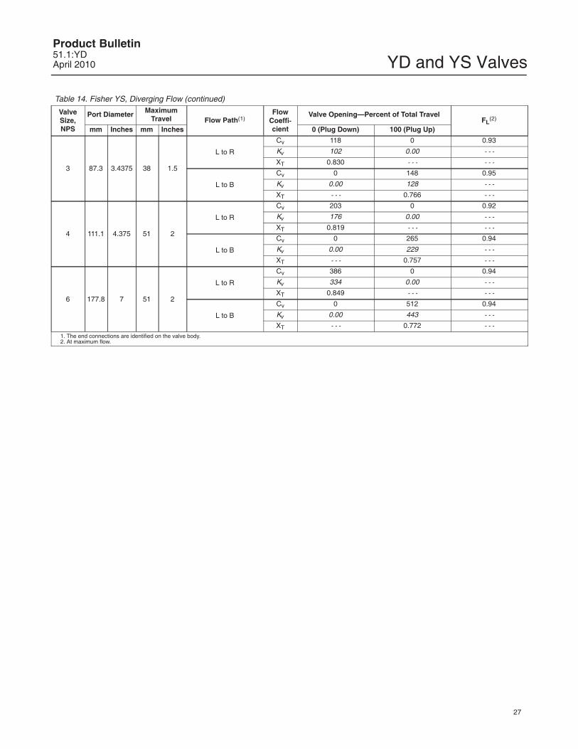
Table 14. Fisher YS, Diverging Flow (continued)
ValveSize,NPS
Port Diameter MaximumTravel Flow Path(1)
FlowCoeffi-cient
Valve Opening—Percent of Total TravelFL
(2)
mm Inches mm Inches 0 (Plug Down) 100 (Plug Up)
3 87.3 3.4375 38 1.5
L to R
Cv 118 0 0.93
Kv 102 0.00 - - -
XT 0.830 - - - - - -
L to B
Cv 0 148 0.95
Kv 0.00 128 - - -
XT - - - 0.766 - - -
4 111.1 4.375 51 2
L to R
Cv 203 0 0.92
Kv 176 0.00 - - -
XT 0.819 - - - - - -
L to B
Cv 0 265 0.94
Kv 0.00 229 - - -
XT - - - 0.757 - - -
6 177.8 7 51 2
L to R
Cv 386 0 0.94
Kv 334 0.00 - - -
XT 0.849 - - - - - -
L to B
Cv 0 512 0.94
Kv 0.00 443 - - -
XT - - - 0.772 - - -1. The end connections are identified on the valve body.2. At maximum flow.
YD and YS ValvesProduct Bulletin
51.1:YDApril 2010
28
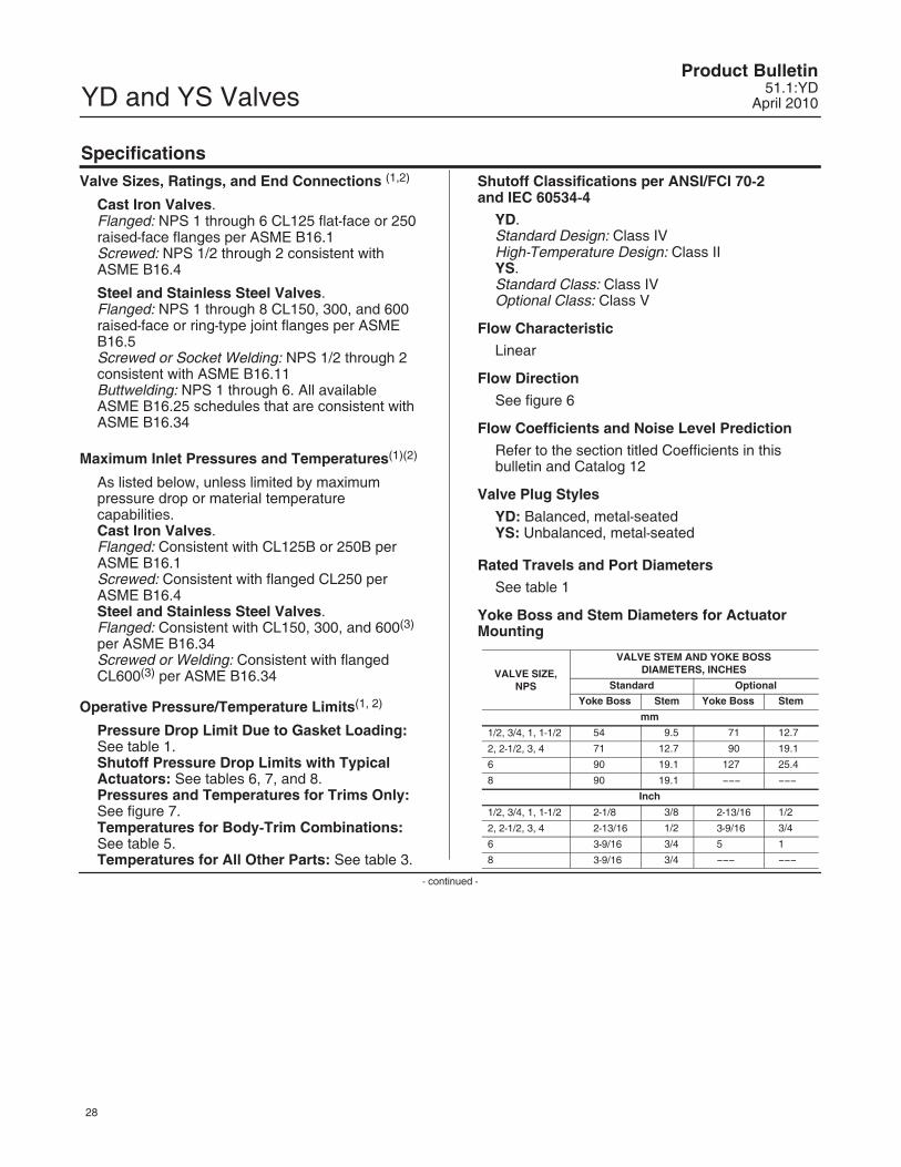
SpecificationsValve Sizes, Ratings, and End Connections (1,2)
Cast Iron Valves.Flanged: NPS 1 through 6 CL125 flat-face or 250raised-face flanges per ASME B16.1Screwed: NPS 1/2 through 2 consistent withASME B16.4
Steel and Stainless Steel Valves.Flanged: NPS 1 through 8 CL150, 300, and 600raised-face or ring-type joint flanges per ASMEB16.5Screwed or Socket Welding: NPS 1/2 through 2consistent with ASME B16.11Buttwelding: NPS 1 through 6. All available ASME B16.25 schedules that are consistent withASME B16.34
Maximum Inlet Pressures and Temperatures(1)(2)
As listed below, unless limited by maximumpressure drop or material temperaturecapabilities.Cast Iron Valves.Flanged: Consistent with CL125B or 250B perASME B16.1Screwed: Consistent with flanged CL250 perASME B16.4Steel and Stainless Steel Valves.Flanged: Consistent with CL150, 300, and 600(3)
per ASME B16.34Screwed or Welding: Consistent with flangedCL600(3) per ASME B16.34
Operative Pressure/Temperature Limits(1, 2)
Pressure Drop Limit Due to Gasket Loading:See table 1.Shutoff Pressure Drop Limits with TypicalActuators: See tables 6, 7, and 8.Pressures and Temperatures for Trims Only:See figure 7.Temperatures for Body-Trim Combinations:See table 5.Temperatures for All Other Parts: See table 3.
Shutoff Classifications per ANSI/FCI 70-2 and IEC 60534-4
YD.Standard Design: Class IVHigh-Temperature Design: Class IIYS.Standard Class: Class IVOptional Class: Class V
Flow Characteristic
Linear
Flow Direction
See figure 6
Flow Coefficients and Noise Level Prediction
Refer to the section titled Coefficients in thisbulletin and Catalog 12
Valve Plug Styles
YD: Balanced, metal-seatedYS: Unbalanced, metal-seated
Rated Travels and Port Diameters
See table 1
Yoke Boss and Stem Diameters for ActuatorMounting
VALVE SIZE,NPS
VALVE STEM AND YOKE BOSSDIAMETERS, INCHES
Standard Optional
Yoke Boss Stem Yoke Boss Stem
mm
1/2, 3/4, 1, 1-1/2 54 9.5 71 12.7
2, 2-1/2, 3, 4 71 12.7 90 19.1
6 90 19.1 127 25.4
8 90 19.1 ��� ���
Inch
1/2, 3/4, 1, 1-1/2 2-1/8 3/8 2-13/16 1/2
2, 2-1/2, 3, 4 2-13/16 1/2 3-9/16 3/4
6 3-9/16 3/4 5 1
8 3-9/16 3/4 ��� ���
- continued -
YD and YS ValvesProduct Bulletin51.1:YDApril 2010
29
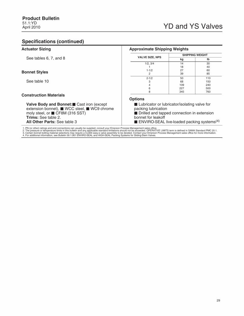
Specifications (continued)Actuator Sizing
See tables 6, 7, and 8
Bonnet Styles
See table 10
Construction Materials
Valve Body and Bonnet:� Cast iron (exceptextension bonnet), � WCC steel, � WC9 chromemoly steel, or � CF8M (316 SST)Trims: See table 2.All Other Parts: See table 3
Approximate Shipping Weights
VALVE SIZE, NPSSHIPPING WEIGHT
kg lb
1/2, 3/41
1-1/22
14182739
30406085
2-1/23468
5068109227345
110150240500760
Options� Lubricator or lubricator/isolating valve forpacking lubrication� Drilled and tapped connection in extensionbonnet for leakoff� ENVIRO-SEAL live-loaded packing systems(4)
1. PN (or other) ratings and end connections can usually be supplied; consult your Emerson Process Management sales office.2. The pressure or temperature limits in this bulletin and any applicable standard limitations should not be exceeded. OPERATIVE LIMITS term is defined in SAMA Standard PMC 20.1.3. Certain bonnet bolting material selections may require a CL600 easy-e valve assembly to be derated. Contact your Emerson Process Management sales office for more information.4. For additional information, see Bulletin 59.1:061 ENVIRO-SEAL and HIGH-SEAL Packing Systems for Sliding-Stem Valves.
YD and YS ValvesProduct Bulletin
51.1:YDApril 2010
30
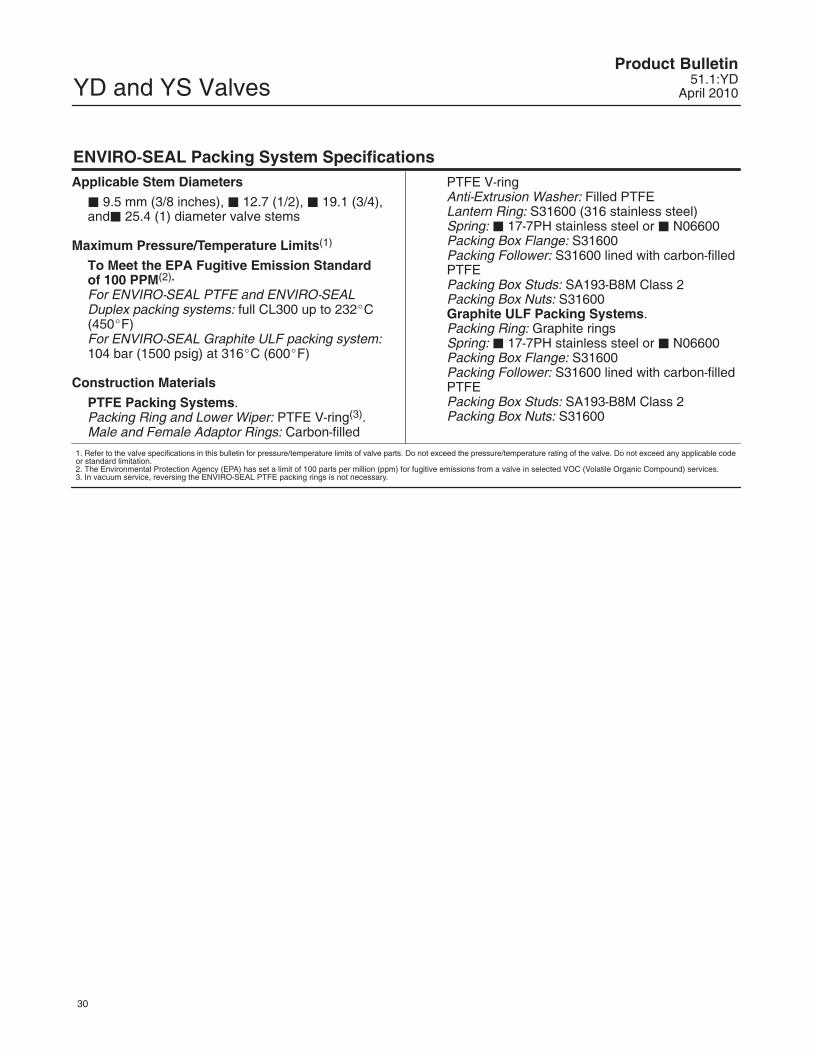
ENVIRO-SEAL Packing System SpecificationsApplicable Stem Diameters
� 9.5 mm (3/8 inches), � 12.7 (1/2), � 19.1 (3/4),and� 25.4 (1) diameter valve stems
Maximum Pressure/Temperature Limits(1)
To Meet the EPA Fugitive Emission Standardof 100 PPM(2).
For ENVIRO-SEAL PTFE and ENVIRO-SEALDuplex packing systems: full CL300 up to 232�C(450�F)For ENVIRO-SEAL Graphite ULF packing system:104 bar (1500 psig) at 316�C (600�F)
Construction Materials
PTFE Packing Systems.Packing Ring and Lower Wiper: PTFE V-ring(3).Male and Female Adaptor Rings: Carbon-filled
PTFE V-ringAnti-Extrusion Washer: Filled PTFELantern Ring: S31600 (316 stainless steel)Spring: � 17-7PH stainless steel or � N06600Packing Box Flange: S31600Packing Follower: S31600 lined with carbon-filledPTFEPacking Box Studs: SA193-B8M Class 2Packing Box Nuts: S31600Graphite ULF Packing Systems.Packing Ring: Graphite ringsSpring: � 17-7PH stainless steel or � N06600Packing Box Flange: S31600Packing Follower: S31600 lined with carbon-filledPTFEPacking Box Studs: SA193-B8M Class 2Packing Box Nuts: S31600
1. Refer to the valve specifications in this bulletin for pressure/temperature limits of valve parts. Do not exceed the pressure/temperature rating of the valve. Do not exceed any applicable codeor standard limitation.2. The Environmental Protection Agency (EPA) has set a limit of 100 parts per million (ppm) for fugitive emissions from a valve in selected VOC (Volatile Organic Compound) services.3. In vacuum service, reversing the ENVIRO-SEAL PTFE packing rings is not necessary.
YD and YS ValvesProduct Bulletin51.1:YDApril 2010
31
Note
Neither Emerson, Emerson ProcessManagement, nor any of their affiliatedentities assumes responsibility for theselection, use, or maintenance of anyproduct. Responsibility for theselection, use, and maintenance of anyproduct remains with the purchaserand end user.
YD and YS ValvesProduct Bulletin
51.1:YDApril 2010
32
Emerson Process Management Marshalltown, Iowa 50158 USASorocaba, 18087 BrazilChatham, Kent ME4 4QZ UKDubai, United Arab EmiratesSingapore 128461 Singapore
�Fisher Controls International LLC 1989, 2010; All Rights Reserved
www.Fisher.com
The contents of this publication are presented for informational purposes only, and while every effort has been made to ensure their accuracy, theyare not to be construed as warranties or guarantees, express or implied, regarding the products or services described herein or their use orapplicability. All sales are governed by our terms and conditions, which are available upon request. We reserve the right to modify or improve thedesigns or specifications of such products at any time without notice. Neither Emerson, Emerson Process Management, nor any of their affiliatedentities assumes responsibility for the selection, use or maintenance of any product. Responsibility for proper selection, use, and maintenance ofany product remains solely with the purchaser and end user.
Fisher, easy-e, and ENVIRO-SEAL are marks owned by one of the companies in the Emerson Process Management business division of EmersonElectric Co. Emerson Process Management, Emerson, and the Emerson logo are trademarks and service marks of Emerson Electric Co. All othermarks are the property of their respective owners.