Embed Size (px)
Citation preview
p. �
Gernot Hoffmann
Color management signal flow diagrams
CMS flow charts
2013 / 2014
p. �
� Introduction
� Nomenclature for colors, grays and spots
3 Tone reproduction curves (TRC)
4 Gray and black
5 Convert to profile: RGB → RGB
6 Convert to profile: RGB → CMYK
7 Assign a profile: RGB
8 Assign a profile: CMYK
9 Make a screenshot: RGB → RGB
�0 Make a screenshot: CMYK → RGB
�� Show a screenshot: RGB
�� Soft proof: RGB → RGB / numbers not preserved
�3 Soft proof: RGB →RGB / numbers preserved
�4 Soft proof: RGB →CMYK
�5 Soft proof: CMYK → CMYK / numbers not preserved
�6 Soft proof: CMYK → CMYK / numbers preserved
�7 Soft proof: Gray →Gray / numbers not preserved
�8 Soft proof: Gray →Gray / numbers preserved
�9 Soft proof: RGB →Monitor Profile / numbers not preserved
�0 Soft proof: RGB →Monitor Profile / numbers preserved
�� Soft proof: RGB → Monitor RGB (Photoshop nomenclature)
�� Printing by an ideal RIP (Raster image processor)
�3 Poster printing by RIP
�4 Proof printing by RIP
�5 Offset printing by RIP
�6 References
Use page number area for jumping to Table of contents
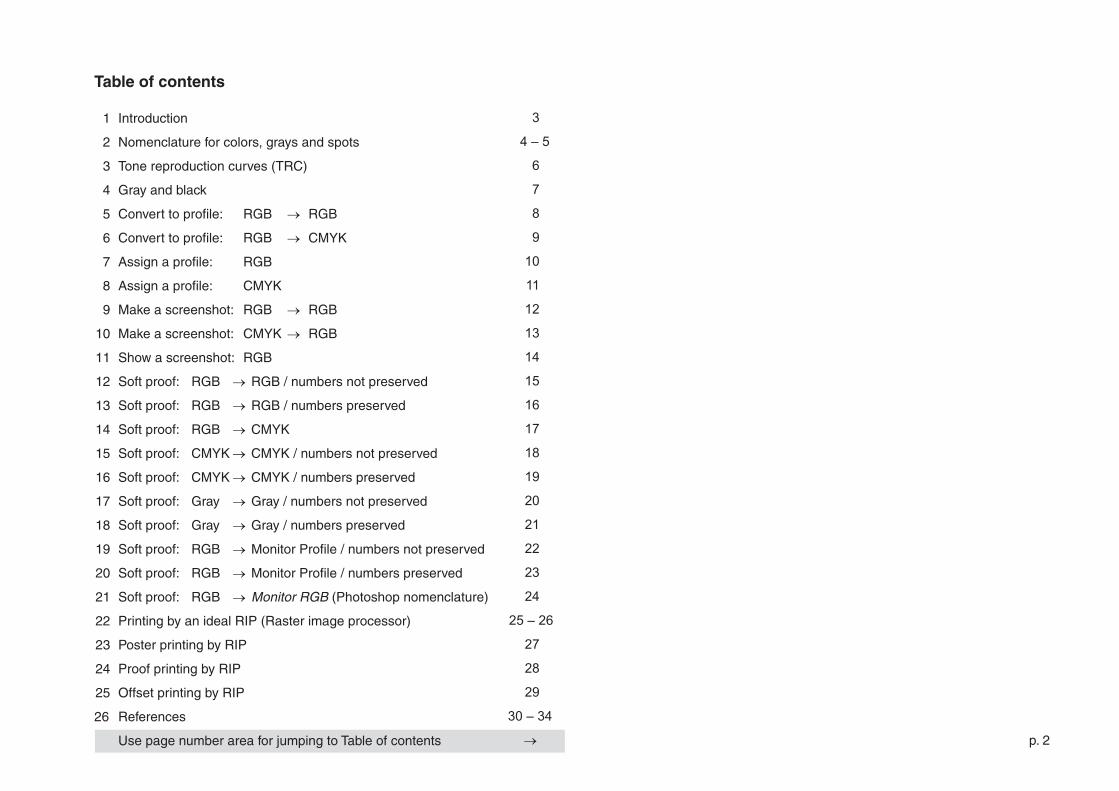
Table of contents
3
4–5
6
7
8
9
10
11
12
13
14
15
16
17
18
19
20
21
22
23
24
25–26
27
28
29
30–34
→
p. 3
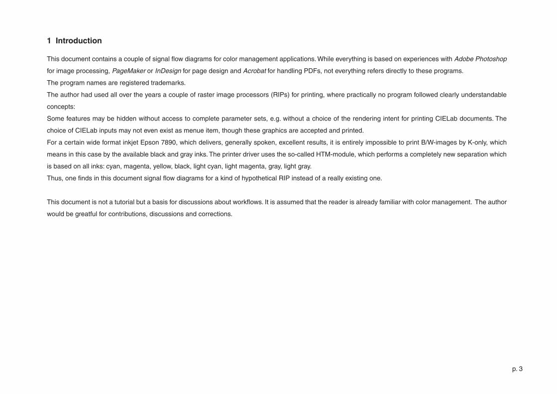
This document contains a couple of signal flow diagrams for color management applications. While everything is based on experiences with Adobe Photoshop
for image processing, PageMaker or InDesign for page design and Acrobat for handling PDFs, not everything refers directly to these programs.
The program names are registered trademarks.
The author had used all over the years a couple of raster image processors (RIPs) for printing, where practically no program followed clearly understandable
concepts:
Some features may be hidden without access to complete parameter sets, e.g. without a choice of the rendering intent for printing CIELab documents. The
choice of CIELab inputs may not even exist as menue item, though these graphics are accepted and printed.
For a certain wide format inkjet Epson 7890, which delivers, generally spoken, excellent results, it is entirely impossible to print B/W-images by K-only, which
means in this case by the available black and gray inks. The printer driver uses the so-called HTM-module, which performs a completely new separation which
is based on all inks: cyan, magenta, yellow, black, light cyan, light magenta, gray, light gray.
Thus, one finds in this document signal flow diagrams for a kind of hypothetical RIP instead of a really existing one.
This document is not a tutorial but a basis for discussions about workflows. It is assumed that the reader is already familiar with color management. The author
would be greatful for contributions, discussions and corrections.
1 Introduction
p. 4
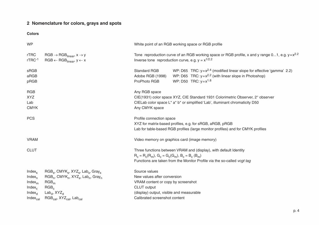
Colors
WP White point of an RGB working space or RGB profile
rTRC RGB →RGBlinear, x →y Tone reproduction curve of an RGB working space or RGB profile, x and y range 0...�, e.g. y=x�.� rTRC-� RGB ←RGBlinear, y ←x Inverse tone reproduction curve, e.g. y = x�/�.�
sRGB Standard RGB WP: D65 TRC: y=x�.4 (modified linear slope for effective ‘gamma’ �.�)aRGB Adobe RGB (�998) WP: D65 TRC: y=x�.� (with linear slope in Photoshop)pRGB ProPhoto RGB WP: D50 TRC: y=x�.8
RGB Any RGB spaceXYZ CIE(�93�) color space XYZ, CIE Standard �93� Colorimetric Observer, �° observer Lab CIELab color space L* a* b* or simplified ‘Lab’, illuminant chromaticity D50 CMYK Any CMYK space
PCS Profile connection space XYZ for matrix-based profiles, e.g. for sRGB, aRGB, pRGB Lab for table-based RGB profiles (large monitor profiles) and for CMYK profiles VRAM Video memory on graphics card (image memory)
CLUT Three functions between VRAM and (display), with default Identity Rc = Rc(Rm), Gc = Gc(Gm), Bc = Bc (Bm) Functions are taken from the Monitor Profile via the so-called vcgt tag
Indexs RGBs, CMYKs, XYZs, Labs, Grays Source valuesIndexn RGBn, CMYKn, XYZs, Labn, Grayn New values after conversion Indexm RGBm VRAM content or copy by screenshotIndexc RGBc CLUT outputIndexd Labd, XYZd (display) output, visible and measurableIndexcal RGBcal, XYZcal, Labcal Calibrated screenshot content
2 Nomenclature for colors, grays and spots
p. 5
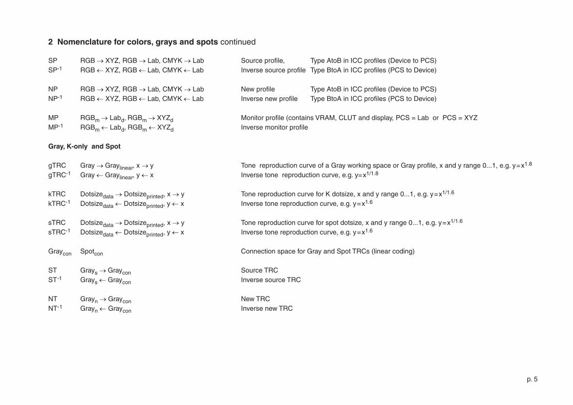
SP RGB →XYZ, RGB → Lab, CMYK → Lab Source profile, Type AtoB in ICC profiles (Device to PCS)SP-� RGB ←XYZ, RGB ←Lab, CMYK ←Lab Inverse source profile Type BtoA in ICC profiles (PCS to Device)
NP RGB →XYZ, RGB → Lab, CMYK → Lab New profile Type AtoB in ICC profiles (Device to PCS)NP-� RGB ←XYZ, RGB ←Lab, CMYK ←Lab Inverse new profile Type BtoA in ICC profiles (PCS to Device)
MP RGBm → Labd, RGBm → XYZd Monitor profile (contains VRAM, CLUT and display, PCS = Lab or PCS = XYZ MP-� RGBm ←Labd, RGBm ←XYZd Inverse monitor profile
Gray, K-only and Spot
gTRC Gray →Graylinear, x →y Tone reproduction curve of a Gray working space or Gray profile, x and y range 0...�, e.g. y=x�.8 gTRC-� Gray ←Graylinear, y ←x Inverse tone reproduction curve, e.g. y=x�/�.8
kTRC Dotsizedata → Dotsizeprinted, x → y Tone reproduction curve for K dotsize, x and y range 0...�, e.g. y=x�/�.6 kTRC-� Dotsizedata ←Dotsizeprinted, y ←x Inverse tone reproduction curve, e.g. y=x�.6
sTRC Dotsizedata → Dotsizeprinted, x → y Tone reproduction curve for spot dotsize, x and y range 0...�, e.g. y=x�/�.6 sTRC-� Dotsizedata ←Dotsizeprinted, y ←x Inverse tone reproduction curve, e.g. y=x�.6
Graycon Spotcon Connection space for Gray and Spot TRCs (linear coding)
ST Grays →Graycon Source TRCST-� Grays ←Graycon Inverse source TRC
NT Grayn →Graycon New TRCNT-� Grayn ←Graycon Inverse new TRC
2 Nomenclature for colors, grays and spots continued
p. 6
Gamma encodingrTRC-�
y = x�/�.�
DataGraylinear
0=black
�=white
RGB MonitorrTRC
y = x�.�
Process dot gainkTRC
y = x�/�.6
DataDotlinear
0=white
�=black
DataDot
0=white
�=black
Inverse dot gainkTRC-�
y = x�.6
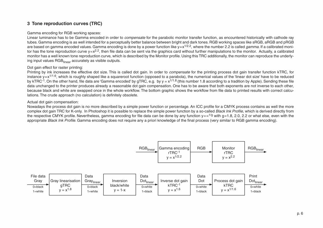
3 Tone reproduction curves (TRC)
Gamma encoding for RGB working spaces:Linear luminance has to be Gamma encoded in order to compensate for the parabolic monitor transfer function, as encountered historically with cathode ray tubes. Gamma encoding is as well intended for a perceptually better balance between bright and dark tones. RGB working spaces like sRGB, aRGB and pRGB are based on gamma encoded values. Gamma encoding is done by a power function like y=x�/�.�, where the number �.� is called gamma. If a calibrated moni-tor has the tone reproduction curve y=x�.�, then file data can be sent via the graphics card without further manipulations to the monitor. Actually, a calibrated monitor has a well known tone reproduction curve, which is described by the Monitor profile. Using this TRC additionally, the monitor can reproduce the underly-ing input values RGBlinear accurately as visible outputs.
Dot gain effect for raster printing:Printing by ink increases the effective dot size. This is called dot gain. In order to compensate for the printing process dot gain transfer function kTRC, for instance y=x�/�.6, which is roughly shaped like a squareroot function (opposed to a parabola), the numerical values of the ‘linear dot size’ have to be reduced by kTRC-�. On the other hand, file data are ‘Gamma encoded’ by gTRC, e.g. by y = x�/�.8 (this number �.8 according to a tradition by Apple). Sending these file data unchanged to the printer produces already a reasonable dot gain compensation. One has to be aware that both exponents are not inverse to each other, because black and white are swapped once in the whole workflow. The bottom graphic shows the workflow from file data to printed results with correct calcu-lations. The crude approach (no calculation) is definitely obsolete.
Actual dot gain compensation: Nowadays the process dot gain is no more described by a simple power function or percentage. An ICC profile for a CMYK process contains as well the more complex dot gain TRC for K-only. In Photoshop it is possible to replace the simple power function by a so-called Black Ink Profile, which is derived directly from the respective CMYK profile. Nevertheless, gamma encoding for file data can be done by any function y==�/g with g=�.8, �.0, �.� or what else, even with the appropriate Black Ink Profile. Gamma encoding does not require any a priori knowledge of the final process (very similar to RGB gamma encoding).
Inversionblack/white
y = �-x
RGBlinear
Gray linearisation gTRC
y = x�.8
File dataGray
0=black
�=white
RGBlinear
PrintDotlinear
0=white
�=black
p. 7
RGB
GrayencodinggTRC-�
y = x�/�.8
Grayscale
0=black
�=white
Source RGB
Inv.gammaencoding
rTRCy = x�.�
RGB
linear
RGB to YMatrix Cxr
Ygray R = YgrayG = YgrayB = Ygray
RGBgray
linear
Gammaencoding rTRC-�
y = x�/�.�
RGBgray
0=black
�=white
Indexedcolor
Ygray
Source Gray
Graylinearisation
gTRCy = x�.8
Gray
0=black
�=white
GraylinearYgray Y to XYZ XYZgray XYZ
to LabLab CMYKgray
Rich black
CMYKoutputprofile
K
Y
M
C
CMYKgray
K-only
0
0
0
Inverse dot gainkTRC-�
y = x�.6
Inversiony = �-x
Dotlinear
0=white
�=black
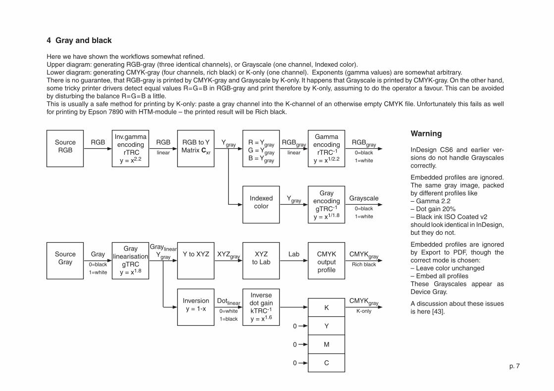
4 Gray and black
Here we have shown the workflows somewhat refined. Upper diagram: generating RGB-gray (three identical channels), or Grayscale (one channel, Indexed color). Lower diagram: generating CMYK-gray (four channels, rich black) or K-only (one channel). Exponents (gamma values) are somewhat arbitrary.There is no guarantee, that RGB-gray is printed by CMYK-gray and Grayscale by K-only. It happens that Grayscale is printed by CMYK-gray. On the other hand, some tricky printer drivers detect equal values R=G=B in RGB-gray and print therefore by K-only, assuming to do the operator a favour. This can be avoided by disturbing the balance R=G=B a little. This is usually a safe method for printing by K-only: paste a gray channel into the K-channel of an otherwise empty CMYK file. Unfortunately this fails as well for printing by Epson 7890 with HTM-module – the printed result will be Rich black.
Warning
InDesign CS6 and earlier ver-sions do not handle Grayscales correctly.
Embedded profiles are ignored.The same gray image, packed by different profiles like – Gamma �.�– Dot gain �0%– Black ink ISO Coated v� should look identical in InDesign, but they do not.
Embedded profiles are ignored by Export to PDF, though the correct mode is chosen:– Leave color unchanged– Embed all profiles These Grayscales appear as Device Gray.
A discussion about these issues is here [43].
p. 8
RGBm VRAM RGBm CLUT RGBc Monitor(display)
LabdMonitorprofileMP-�
LabnNewsourceRGBn
RGBn XYZnNewprofile
NP
Use New source (new numbers) and New profile
Optionally save
XYZto
Lab
SourceRGBs
RGBs Sourceprofile
SP
XYZs RGBnNewprofileNP-�
Use input XYZn if
matrix-based
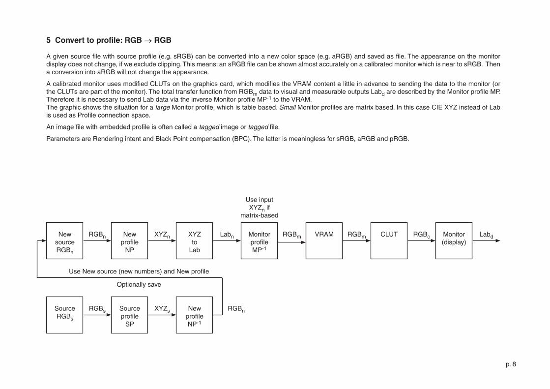
5 Convert to profile: RGB → RGB
A given source file with source profile (e.g. sRGB) can be converted into a new color space (e.g. aRGB) and saved as file. The appearance on the monitor display does not change, if we exclude clipping. This means: an sRGB file can be shown almost accurately on a calibrated monitor which is near to sRGB. Then a conversion into aRGB will not change the appearance.
A calibrated monitor uses modified CLUTs on the graphics card, which modifies the VRAM content a little in advance to sending the data to the monitor (or the CLUTs are part of the monitor). The total transfer function from RGBm data to visual and measurable outputs Labd are described by the Monitor profile MP. Therefore it is necessary to send Lab data via the inverse Monitor profile MP-� to the VRAM.The graphic shows the situation for a large Monitor profile, which is table based. Small Monitor profiles are matrix based. In this case CIE XYZ instead of Lab is used as Profile connection space.
An image file with embedded profile is often called a tagged image or tagged file.
Parameters are Rendering intent and Black Point compensation (BPC). The latter is meaningless for sRGB, aRGB and pRGB.
p. 9
RGBm VRAM RGBm CLUT RGBc Monitor(display)
LabdMonitorprofileMP-�
LabnNewsourceCMYKn
CMYKn LabnNewprofile
NP
Use new source (new numbers) and New profile
Optionally save
SourceRGBs
RGBs Sourceprofile
SP
XYZs Labs NewprofileNP-�
XYZto
Lab
CMYKn
Use input XYZn if
matrix-based
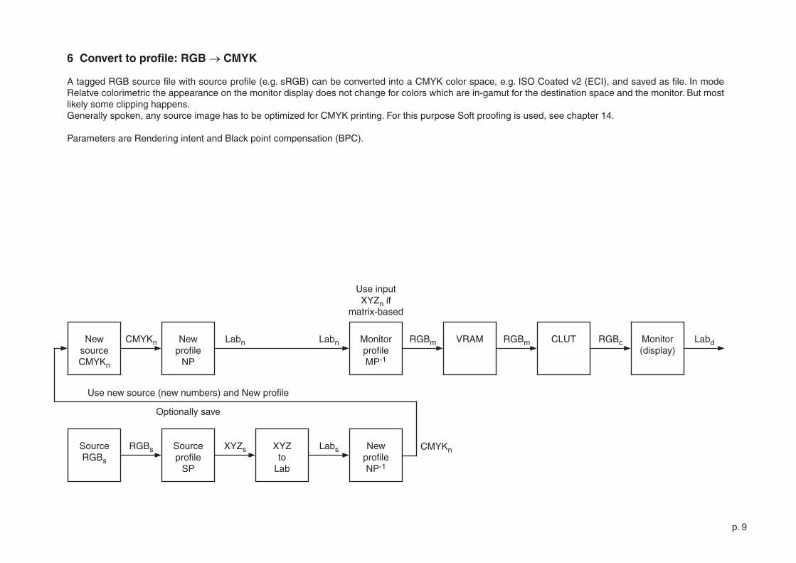
6 Convert to profile: RGB → CMYK
A tagged RGB source file with source profile (e.g. sRGB) can be converted into a CMYK color space, e.g. ISO Coated v� (ECI), and saved as file. In mode Relatve colorimetric the appearance on the monitor display does not change for colors which are in-gamut for the destination space and the monitor. But most likely some clipping happens. Generally spoken, any source image has to be optimized for CMYK printing. For this purpose Soft proofing is used, see chapter �4.
Parameters are Rendering intent and Black point compensation (BPC).
p. �0
RGBm VRAM RGBm CLUT RGBc Monitor(display)
LabdMonitorprofileMP-�
SourceRGBs
RGBs XYZnNewprofile
NP
Use old source (old numbers) and New profile
Optionally save
LabnXYZto
Lab
Use input XYZn if
matrix-based
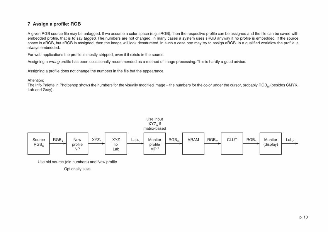
7 Assign a profile: RGB
A given RGB source file may be untagged. If we assume a color space (e.g. sRGB), then the respective profile can be assigned and the file can be saved with embedded profile, that is to say tagged. The numbers are not changed. In many cases a system uses sRGB anyway if no profile is embedded. If the source space is aRGB, but sRGB is assigned, then the image will look desaturated. In such a case one may try to assign aRGB. In a qualified workflow the profile is always embedded.
For web applications the profile is mostly stripped, even if it exists in the source.
Assigning a wrong profile has been occasionally recommended as a method of image processing. This is hardly a good advice.
Assigning a profile does not change the numbers in the file but the appearance.
Attention: The Info Palette in Photoshop shows the numbers for the visually modified image – the numbers for the color under the cursor, probably RGBm (besides CMYK, Lab and Gray).
p. ��
RGBm VRAM RGBm CLUT RGBc Monitor(display)
LabdMonitorprofileMP-�
SourceCMYKs
CMYKs LabnNewprofile
NP
Use old source (old numbers) and New profile
Optionally save
Labn
Use input XYZn if
matrix-based
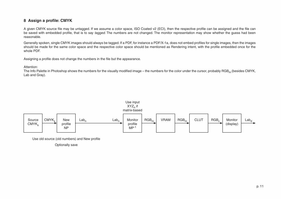
8 Assign a profile: CMYK
A given CMYK source file may be untagged. If we assume a color space, ISO Coated v� (ECI), then the respective profile can be assigned and the file can be saved with embedded profile, that is to say tagged. The numbers are not changed. The monitor representation may show whether the guess had been reasonable.
Generally spoken, single CMYK images should always be tagged. If a PDF, for instance a PDF/X-�a, does not embed profiles for single images, then the images should be made for the same color space and the respective color space should be mentioned as Rendering intent, with the profile embedded once for the whole PDF.
Assigning a profile does not change the numbers in the file but the appearance.
Attention: The Info Palette in Photoshop shows the numbers for the visually modified image – the numbers for the color under the cursor, probably RGBm (besides CMYK, Lab and Gray).
p. ��
SourceRGBs
RGBs RGBm VRAM RGBmSourceprofile
SP
CLUT RGBc Monitor(display)
MonitorprofileMP-�
RGBdXYZs LabsXYZto
Lab
Monitorprofile
MP
LabcalLabto
XYZ
XYZcalWorkprofile
(SPw)-�
RGBwWorkscreenshot
RGBw
Assign monitor profile + Convert to calibration space
Use input XYZs if
matrix-based
Use output XYZcal if
matrix-based
Uncalibrated screenshot
Calibrated screenshot
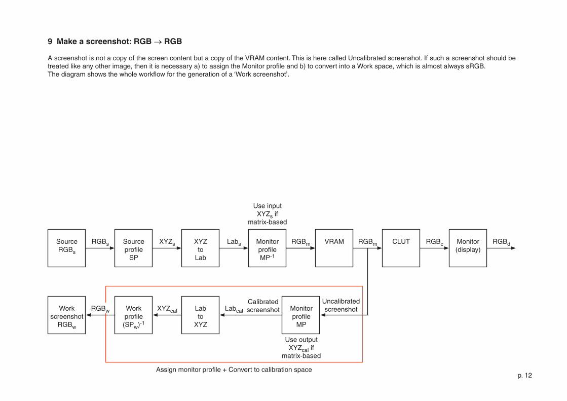
9 Make a screenshot: RGB → RGB
A screenshot is not a copy of the screen content but a copy of the VRAM content. This is here called Uncalibrated screenshot. If such a screenshot should be treated like any other image, then it is necessary a) to assign the Monitor profile and b) to convert into a Work space, which is almost always sRGB.The diagram shows the whole workflow for the generation of a ‘Work screenshot’.
p. �3
SourceCMYKs
CMYKs RGBm VRAM RGBmSourceprofile
SP
CLUT RGBc Monitor(display)
MonitorprofileMP-�
RGBdLabs
Monitorprofile
MP
LabcalLabto
XYZ
XYZcalWorkprofile
(SPw)-�
RGBwWorkscreenshot
RGBw
Assign monitor profile + Convert to calibration space
Use input XYZs if
matrix-based
Use output XYZcal if
matrix-based
Uncalibrated screenshot
Calibrated screenshot
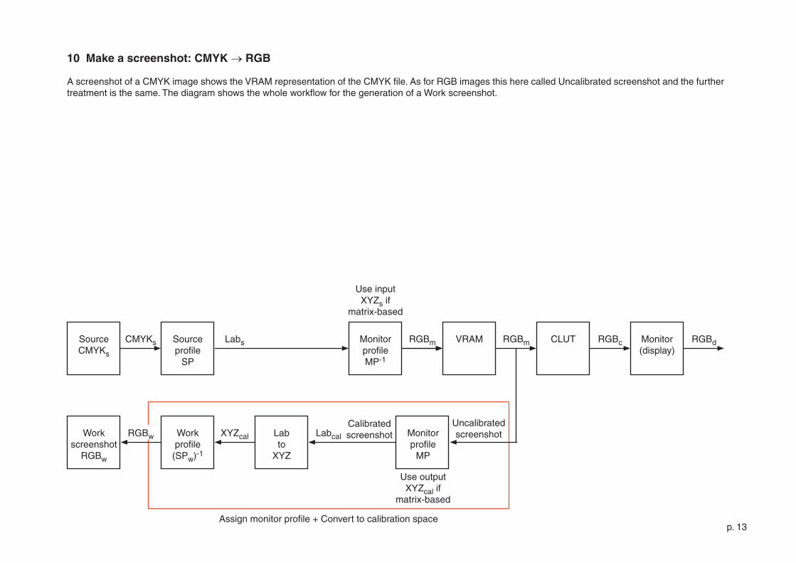
10 Make a screenshot: CMYK → RGB
A screenshot of a CMYK image shows the VRAM representation of the CMYK file. As for RGB images this here called Uncalibrated screenshot and the further treatment is the same. The diagram shows the whole workflow for the generation of a Work screenshot.
p. �4
RGBmUncalibr.screenshot
RGBm
RGBm XYZm VRAM RGBmMonitorprofile
MP
CLUT RGBc Monitor(display)
MonitorprofileMP-�
LabdLabm
RGBcal RGBm VRAM RGBm CLUT RGBc Monitor(display)
LabdXYZs LabsXYZto
Lab
SourceprofileSPcal
MonitorprofileMP-�
XYZto
Lab
Identity operator
Use input XYZm if
matrix-based
Use input XYZs if
matrix-based
Calibratedscreenshot
RGBcal
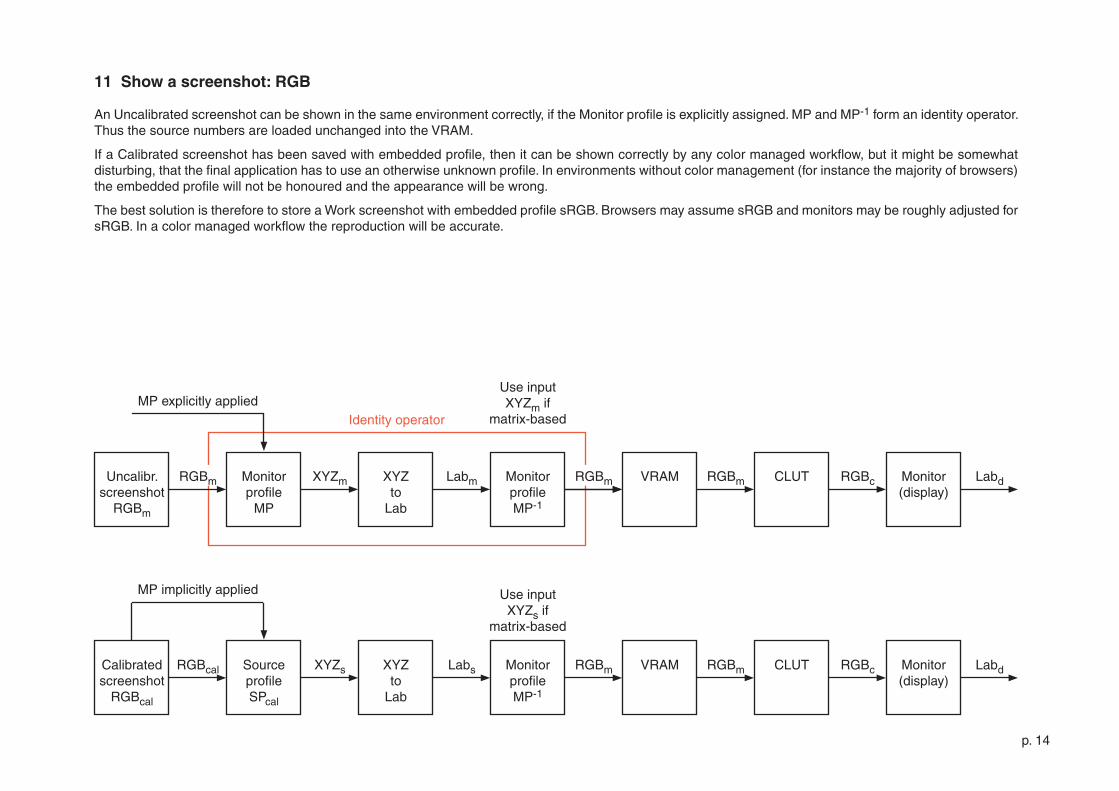
11 Show a screenshot: RGB
An Uncalibrated screenshot can be shown in the same environment correctly, if the Monitor profile is explicitly assigned. MP and MP-� form an identity operator. Thus the source numbers are loaded unchanged into the VRAM.
If a Calibrated screenshot has been saved with embedded profile, then it can be shown correctly by any color managed workflow, but it might be somewhat disturbing, that the final application has to use an otherwise unknown profile. In environments without color management (for instance the majority of browsers) the embedded profile will not be honoured and the appearance will be wrong.
The best solution is therefore to store a Work screenshot with embedded profile sRGB. Browsers may assume sRGB and monitors may be roughly adjusted for sRGB. In a color managed workflow the reproduction will be accurate.
MP implicitly applied
MP explicitly applied
p. �5
SourceRGBs
RGBs LabnSourceprofile
SP
RGBm Monitor LabdXYZs RGBn XYZ to
Lab
MonitorprofileMP-�
NewprofileNP-�
Newprofile
NP
XYZn
VRAM RGBm CLUT RGBc Monitor(display)
RGBm Labd
XYZ to
LabLabs
if |y-x|>ethen draw
gamut warning
y
x
Use input XYZn if
matrix-based
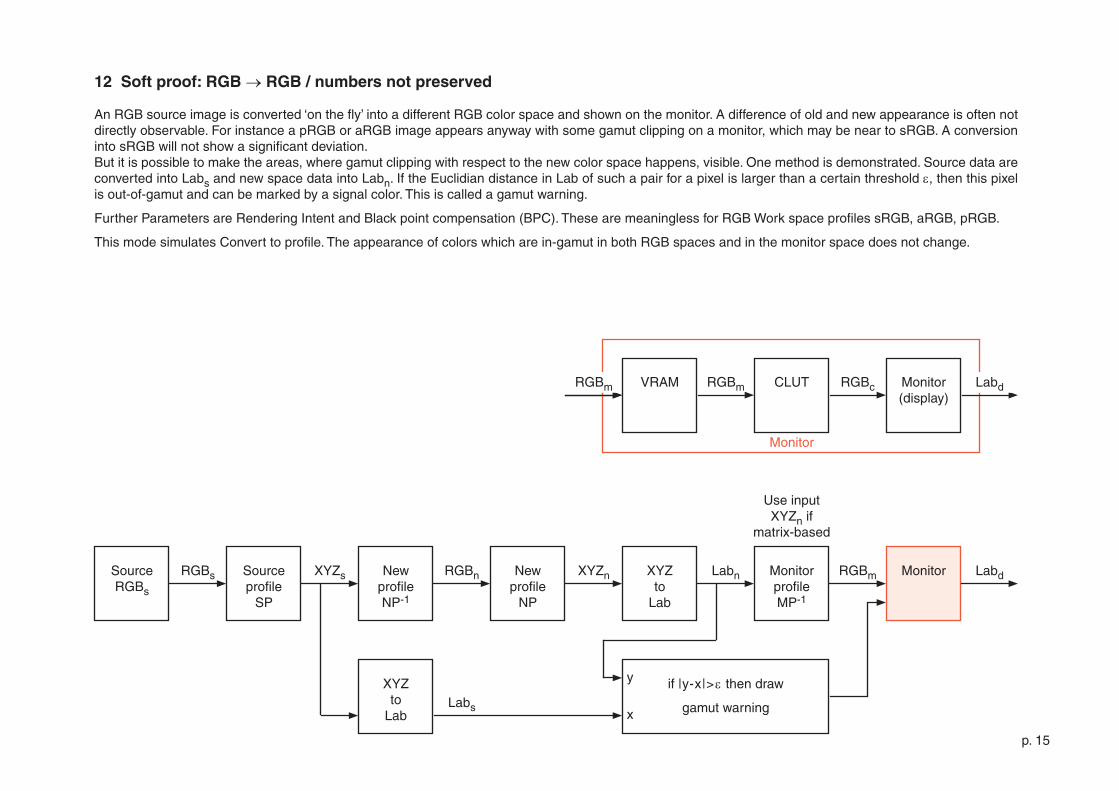
12 Soft proof: RGB → RGB / numbers not preserved
An RGB source image is converted ‘on the fly’ into a different RGB color space and shown on the monitor. A difference of old and new appearance is often not directly observable. For instance a pRGB or aRGB image appears anyway with some gamut clipping on a monitor, which may be near to sRGB. A conversion into sRGB will not show a significant deviation. But it is possible to make the areas, where gamut clipping with respect to the new color space happens, visible. One method is demonstrated. Source data are converted into Labs and new space data into Labn. If the Euclidian distance in Lab of such a pair for a pixel is larger than a certain threshold e, then this pixel is out-of-gamut and can be marked by a signal color. This is called a gamut warning.
Further Parameters are Rendering Intent and Black point compensation (BPC). These are meaningless for RGB Work space profiles sRGB, aRGB, pRGB.
This mode simulates Convert to profile. The appearance of colors which are in-gamut in both RGB spaces and in the monitor space does not change.
Monitor
p. �6
SourceRGBs
RGBs Labn RGBm Monitor LabdRGBs XYZ to
Lab
MonitorprofileMP-�
Newprofile
NP
XYZn
Gamut warning not available
VRAM RGBm CLUT RGBc Monitor(display)
RGBm Labd
Use input XYZn if
matrix-based
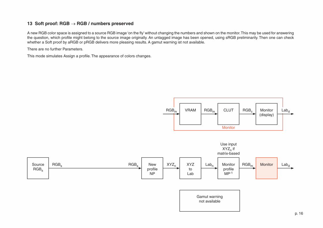
13 Soft proof: RGB → RGB / numbers preserved
A new RGB color space is assigned to a source RGB image ‘on the fly’ without changing the numbers and shown on the monitor. This may be used for answering the question, which profile might belong to the source image originally. An untagged image has been opened, using sRGB preliminarily. Then one can check whether a Soft proof by aRGB or pRGB delivers more pleasing results. A gamut warning ist not available.
There are no further Parameters.
This mode simulates Assign a profile. The appearance of colors changes.
Monitor
p. �7
SourceRGBs
RGBs LabnSourceprofile
SP
RGBm Monitor LabdXYZs Labs Newprofile
NP
MonitorprofileMP-�
XYZto
Lab
NewprofileNP-�
CMYKn
if |y-x|>ethen draw
gamut warning
y
x
VRAM RGBm CLUT RGBc Monitor(display)
RGBm Labd
Use input XYZn if
matrix-based
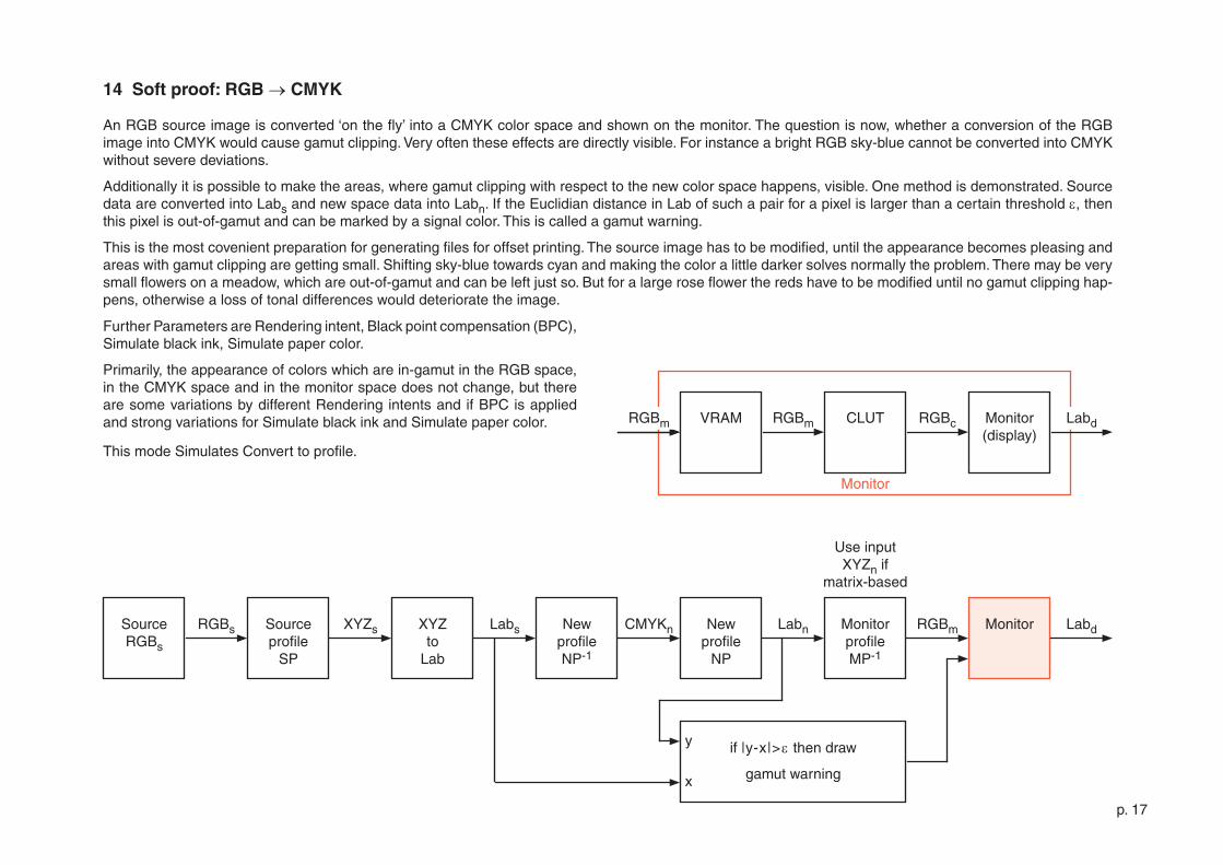
14 Soft proof: RGB → CMYK
An RGB source image is converted ‘on the fly’ into a CMYK color space and shown on the monitor. The question is now, whether a conversion of the RGB image into CMYK would cause gamut clipping. Very often these effects are directly visible. For instance a bright RGB sky-blue cannot be converted into CMYK without severe deviations.
Additionally it is possible to make the areas, where gamut clipping with respect to the new color space happens, visible. One method is demonstrated. Source data are converted into Labs and new space data into Labn. If the Euclidian distance in Lab of such a pair for a pixel is larger than a certain threshold e, then this pixel is out-of-gamut and can be marked by a signal color. This is called a gamut warning.
This is the most covenient preparation for generating files for offset printing. The source image has to be modified, until the appearance becomes pleasing and areas with gamut clipping are getting small. Shifting sky-blue towards cyan and making the color a little darker solves normally the problem. There may be very small flowers on a meadow, which are out-of-gamut and can be left just so. But for a large rose flower the reds have to be modified until no gamut clipping hap-pens, otherwise a loss of tonal differences would deteriorate the image.
Monitor
Further Parameters are Rendering intent, Black point compensation (BPC), Simulate black ink, Simulate paper color.
Primarily, the appearance of colors which are in-gamut in the RGB space, in the CMYK space and in the monitor space does not change, but there are some variations by different Rendering intents and if BPC is applied and strong variations for Simulate black ink and Simulate paper color.
This mode Simulates Convert to profile.
p. �8
SourceCMYKs
CMYKs LabnSourceprofile
SP
RGBm Monitor LabdLabs Labs Newprofile
NP
MonitorprofileMP-�
NewprofileNP-�
CMYKn
if |y-x|>ethen draw
gamut warning
y
x
VRAM RGBm CLUT RGBc Monitor(display)
RGBm Labd
Use input XYZn if
matrix-based
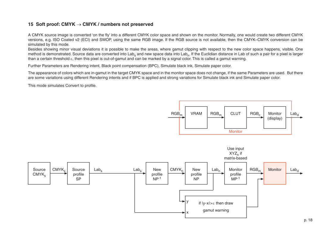
15 Soft proof: CMYK → CMYK / numbers not preserved
A CMYK source image is converted ‘on the fly’ into a different CMYK color space and shown on the monitor. Normally, one would create two different CMYK versions, e.g. ISO Coated v� (ECI) and SWOP, using the same RGB image. If the RGB source is not available, then the CMYK–CMYK conversion can be simulated by this mode. Besides showing minor visual deviations it is possible to make the areas, where gamut clipping with respect to the new color space happens, visible. One method is demonstrated. Source data are converted into Labs and new space data into Labn. If the Euclidian distance in Lab of such a pair for a pixel is larger than a certain threshold e, then this pixel is out-of-gamut and can be marked by a signal color. This is called a gamut warning.
Further Parameters are Rendering intent, Black point compensation (BPC), Simulate black ink, Simulate paper color.
The appearance of colors which are in-gamut in the target CMYK space and in the monitor space does not change, if the same Parameters are used. But there are some variations using different Rendering intents and if BPC is applied and strong variations for Simulate black ink and Simulate paper color.
This mode simulates Convert to profile.
Monitor
p. �9
SourceCMYKs
CMYKs Labn RGBm Monitor LabdNewprofile
NP
MonitorprofileMP-�
CMYKs
Gamut warning not available
VRAM RGBm CLUT RGBc Monitor(display)
RGBm Labd
Use input XYZn if
matrix-based
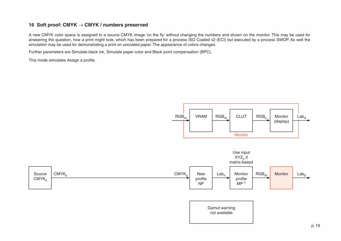
16 Soft proof: CMYK → CMYK / numbers preserved
A new CMYK color space is assigned to a source CMYK image ‘on the fly’ without changing the numbers and shown on the monitor. This may be used for answering the question, how a print might look, which has been prepared for a process ISO Coated v� (ECI) but executed by a process SWOP. As well the simulation may be used for demonstrating a print on uncoated paper. The appearance of colors changes.
Further parameters are Simulate black ink, Simulate paper color and Black point compensation (BPC).
This mode simulates Assign a profile.
Monitor
p. �0
SourceGrays
Grays LabnSourceTRCST
RGBm Monitor LabdGraycon Grayn XYZ to
Lab
MonitorprofileMP-�
NewTRCNT-�
Grayto
XYZ
XYZn
Gamut warning not available
VRAM RGBm CLUT RGBc Monitor(display)
RGBm Labd
Use input XYZn if
matrix-based
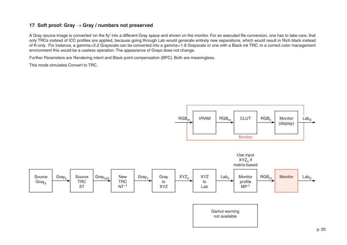
17 Soft proof: Gray → Gray / numbers not preserved
A Gray source image is converted ‘on the fly’ into a different Gray space and shown on the monitor. For an executed file conversion, one has to take care, that only TRCs instead of ICC profiles are applied, because going through Lab would generate entirely new separations, which would result in Rich black instead of K-only. For instance, a gamma=�.� Grayscale can be converted into a gamma=�.8 Grayscale or one with a Black ink TRC. In a correct color management environment this would be a useless operation. The appearance of Grays does not change.
Further Parameters are Rendering intent and Black point compensation (BPC). Both are meaningless.
This mode simulates Convert to TRC.
Monitor
p. ��
SourceGrays
Grays Labn RGBm Monitor LabdGraycon Grayn XYZ to
Lab
MonitorprofileMP-�
NewTRCNT-�
Grayto
XYZ
XYZn
Gamut warning not available
VRAM RGBm CLUT RGBc Monitor(display)
RGBm Labd
Use input XYZn if
matrix-based
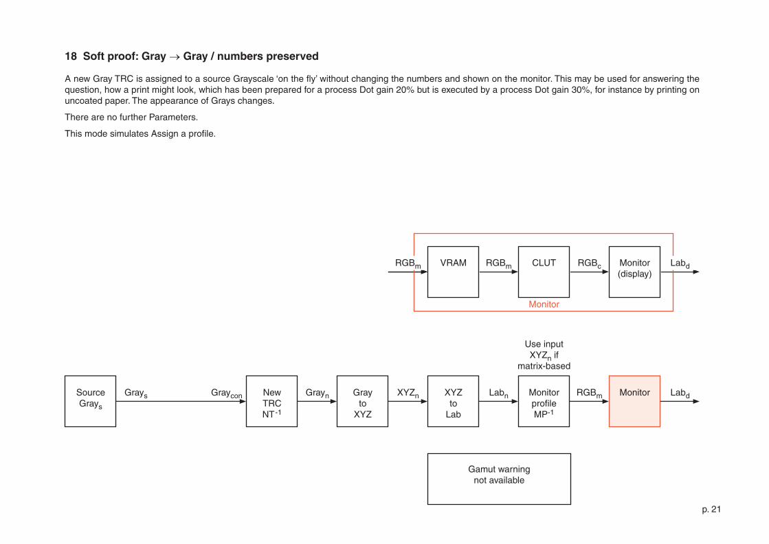
18 Soft proof: Gray → Gray / numbers preserved
A new Gray TRC is assigned to a source Grayscale ‘on the fly’ without changing the numbers and shown on the monitor. This may be used for answering the question, how a print might look, which has been prepared for a process Dot gain �0% but is executed by a process Dot gain 30%, for instance by printing on uncoated paper. The appearance of Grays changes.
There are no further Parameters.
This mode simulates Assign a profile.
Monitor
p. ��
SourceRGBs
RGBs LabnSourceprofile
SP
RGBm Monitor LabdXYZs RGBn XYZ to
Lab
MonitorprofileMP-�
MonitorprofileMP-�
Monitorprofile
MP
XYZn
if |y-x|>ethen draw
gamut warning
y
x
XYZ to
LabLabs
VRAM RGBm CLUT RGBc Monitor(display)
RGBm Labd
Use input XYZn if
matrix-based
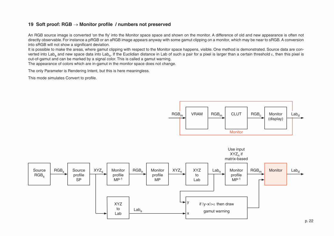
19 Soft proof: RGB → Monitor profile / numbers not preserved
An RGB source image is converted ‘on the fly’ into the Monitor space space and shown on the monitor. A difference of old and new appearance is often not directly observable. For instance a pRGB or an aRGB image appears anyway with some gamut clipping on a monitor, which may be near to sRGB. A conversion into sRGB will not show a significant deviation. It is possible to make the areas, where gamut clipping with respect to the Monitor space happens, visible. One method is demonstrated. Source data are con-verted into Labs and new space data into Labn. If the Euclidian distance in Lab of such a pair for a pixel is larger than a certain threshold e, then this pixel is out-of-gamut and can be marked by a signal color. This is called a gamut warning.The appearance of colors which are in-gamut in the monitor space does not change.
The only Parameter is Rendering Intent, but this is here meaningless.
This mode simulates Convert to profile.
Monitor
p. �3
SourceRGBs
RGBs Labn RGBm Monitor LabdRGBs XYZ to
Lab
MonitorprofileMP-�
Monitorprofile
MP
XYZn
Gamut warning not available
VRAM RGBm CLUT RGBc Monitor(display)
RGBm Labd
Use input XYZn if
matrix-based
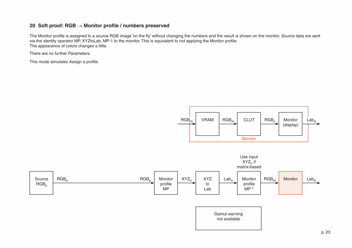
20 Soft proof: RGB → Monitor profile / numbers preserved
The Monitor profile is assigned to a source RGB image ‘on the fly’ without changing the numbers and the result is shown on the monitor. Source data are sent via the identity operator MP, XYZtoLab, MP-� to the monitor. This is equivalent to not applying the Monitor profile.The appearance of colors changes a little.
There are no further Parameters.
This mode simulates Assign a profile.
Monitor
p. �4
SourceRGBs
RGBs RGBm Monitor Labd
VRAM RGBm CLUT RGBc Monitor(display)
RGBm Labd
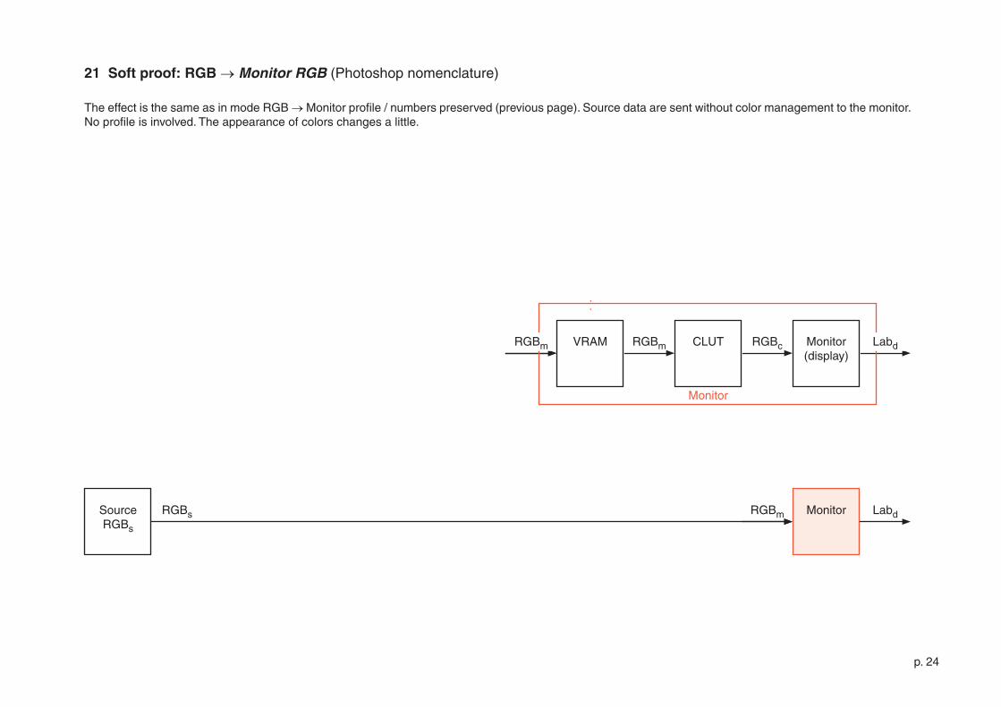
21 Soft proof: RGB → Monitor RGB (Photoshop nomenclature)
The effect is the same as in mode RGB → Monitor profile / numbers preserved (previous page). Source data are sent without color management to the monitor. No profile is involved. The appearance of colors changes a little.
Monitor
p. �5
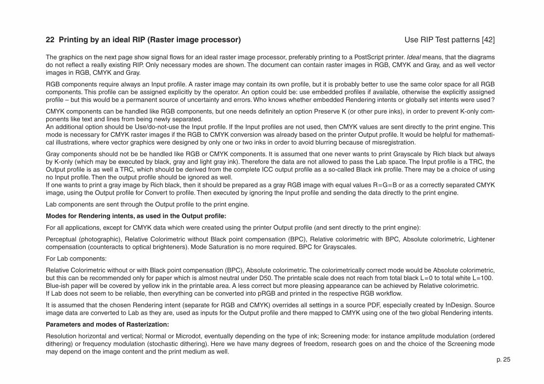
22 Printing by an ideal RIP (Raster image processor)
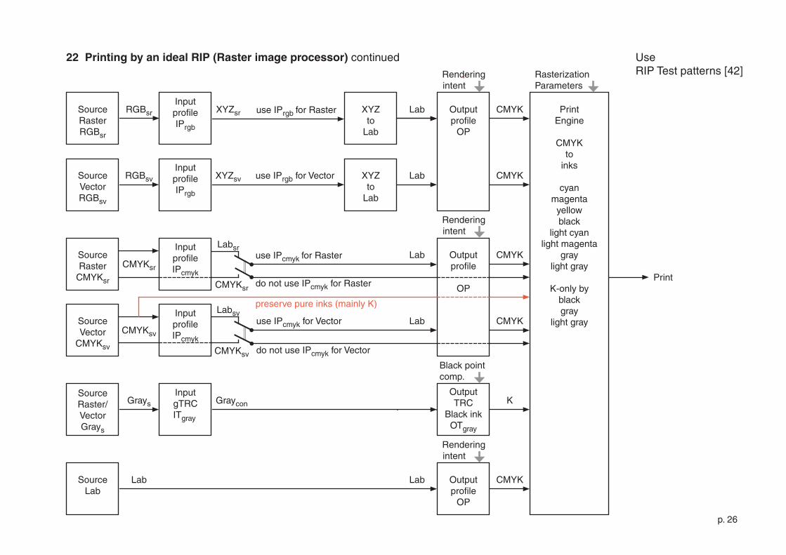
The graphics on the next page show signal flows for an ideal raster image processor, preferably printing to a PostScript printer. Ideal means, that the diagrams do not reflect a really existing RIP. Only necessary modes are shown. The document can contain raster images in RGB, CMYK and Gray, and as well vector images in RGB, CMYK and Gray.
RGB components require always an Input profile. A raster image may contain its own profile, but it is probably better to use the same color space for all RGB components. This profile can be assigned explicitly by the operator. An option could be: use embedded profiles if available, otherwise the explicitly assigned profile – but this would be a permanent source of uncertainty and errors. Who knows whether embedded Rendering intents or globally set intents were used ?
CMYK components can be handled like RGB components, but one needs definitely an option Preserve K (or other pure inks), in order to prevent K-only com-ponents like text and lines from being newly separated. An additional option should be Use/do-not-use the Input profile. If the Input profiles are not used, then CMYK values are sent directly to the print engine. This mode is necessary for CMYK raster images if the RGB to CMYK conversion was already based on the printer Output profile. It would be helpful for mathemati-cal illustrations, where vector graphics were designed by only one or two inks in order to avoid blurring because of misregistration.
Gray components should not be be handled like RGB or CMYK components. It is assumed that one never wants to print Grayscale by Rich black but always by K-only (which may be executed by black, gray and light gray ink). Therefore the data are not allowed to pass the Lab space. The Input profile is a TRC, the Output profile is as well a TRC, which should be derived from the complete ICC output profile as a so-called Black ink profile. There may be a choice of using no Input profile. Then the output profile should be ignored as well.If one wants to print a gray image by Rich black, then it should be prepared as a gray RGB image with equal values R=G=B or as a correctly separated CMYK image, using the Output profile for Convert to profile. Then executed by ignoring the Input profile and sending the data directly to the print engine.
Lab components are sent through the Output profile to the print engine.
Modes for Rendering intents, as used in the Output profile:
For all applications, except for CMYK data which were created using the printer Output profile (and sent directly to the print engine):
Perceptual (photographic), Relative Colorimetric without Black point compensation (BPC), Relative colorimetric with BPC, Absolute colorimetric, Lightener compensation (counteracts to optical brighteners). Mode Saturation is no more required. BPC for Grayscales.
For Lab components:
Relative Colorimetric without or with Black point compensation (BPC), Absolute colorimetric. The colorimetrically correct mode would be Absolute colorimetric, but this can be recommended only for paper which is almost neutral under D50. The printable scale does not reach from total black L=0 to total white L=�00.Blue-ish paper will be covered by yellow ink in the printable area. A less correct but more pleasing appearance can be achieved by Relative colorimetric. If Lab does not seem to be reliable, then everything can be converted into pRGB and printed in the respective RGB workflow.
It is assumed that the chosen Rendering intent (separate for RGB and CMYK) overrides all settings in a source PDF, especially created by InDesign. Source image data are converted to Lab as they are, used as inputs for the Output profile and there mapped to CMYK using one of the two global Rendering intents.
Parameters and modes of Rasterization:
Resolution horizontal and vertical; Normal or Microdot, eventually depending on the type of ink; Screening mode: for instance amplitude modulation (ordered dithering) or frequency modulation (stochastic dithering). Here we have many degrees of freedom, research goes on and the choice of the Screening mode may depend on the image content and the print medium as well.
Use RIP Test patterns [4�]
p. �6
CMYKCMYKsr
SourceRaster
CMYKsr
SourceVector
CMYKsv
InputprofileIPcmyk
InputprofileIPcmyk
use IPcmyk for VectorCMYKsv
use IPcmyk for Raster
do not use IPcmyk for Raster
RGBsrSourceRasterRGBsr
SourceVectorRGBsv
InputprofileIPrgb
InputprofileIPrgb
use IPrgb for VectorRGBsv
XYZto
Lab
Labuse IPrgb for Raster Outputprofile
OP
XYZto
Lab
Lab
CMYK
Outputprofile
OP
XYZsv
Labsr
do not use IPcmyk for Vector
CMYKsr
CMYKsv
Labsv
GraysSourceRaster/VectorGrays
InputgTRC ITgray
OutputTRC
Black inkOTgray
CMYK
CMYK
PrintEngine
CMYK to
inks
cyanmagenta
yellowblack
light cyanlight magenta
graylight gray
K-only byblackgray
light gray
preserve pure inks (mainly K)
Rendering intent
Rendering intent
Rasterization Parameters
Black point comp.
XYZsr
SourceLab
Lab Outputprofile
OP
CMYK
Rendering intent
Lab
K
Lab
Lab
Graycon
22 Printing by an ideal RIP (Raster image processor) continued Use RIP Test patterns [4�]
p. �7
SourceVector
CMYKsv
InputprofileIPcmyk
use IPcmyk for VectorCMYKsv
RGBsrSourceRasterRGBsr
InputprofileIPrgb
XYZto
Lab
Lab Outputprofile
OP
CMYK
Outputprofile
OP
XYZ
do not use IPcmyk for VectorCMYKsv
Lab
Printengine
CMYK to
inks
cyanmagenta
yellowblack
light cyanligh magenta
graylight gray
K-only byblackgray
light gray
preserve pure inks (mainly K)
Rendering intent
Rendering intent
Rasterization parameters
CMYK
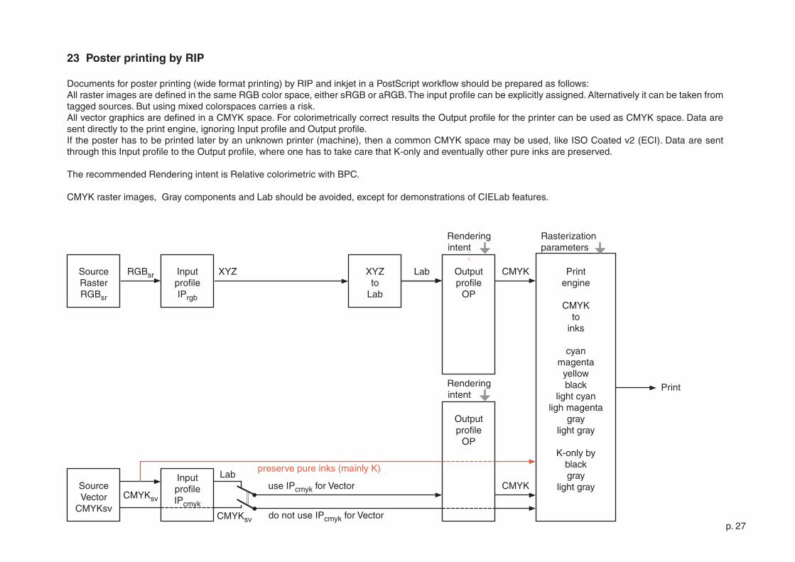
23 Poster printing by RIP
Documents for poster printing (wide format printing) by RIP and inkjet in a PostScript workflow should be prepared as follows:All raster images are defined in the same RGB color space, either sRGB or aRGB. The input profile can be explicitly assigned. Alternatively it can be taken from tagged sources. But using mixed colorspaces carries a risk.All vector graphics are defined in a CMYK space. For colorimetrically correct results the Output profile for the printer can be used as CMYK space. Data are sent directly to the print engine, ignoring Input profile and Output profile.If the poster has to be printed later by an unknown printer (machine), then a common CMYK space may be used, like ISO Coated v� (ECI). Data are sent through this Input profile to the Output profile, where one has to take care that K-only and eventually other pure inks are preserved.
The recommended Rendering intent is Relative colorimetric with BPC.
CMYK raster images, Gray components and Lab should be avoided, except for demonstrations of CIELab features.
p. �8
CMYKsSourceRasterCMYKs
SourceVectorCMYKs
CMYKs
SourceSpots
Spots
Lab Printengine
CMYK to
inks
cyanmagenta
yellowblack
light cyanligh magenta
graylight gray
Rasterization parameters
Outputprofile
OP
Rendering intent
InputprofileIPcmyk
InputprofileIPcmyk
InputsTRCITspot
preserve pure inks (mainly K)
Spotcon
Lab
LabLab
LabSpotto
Lab
CMYK
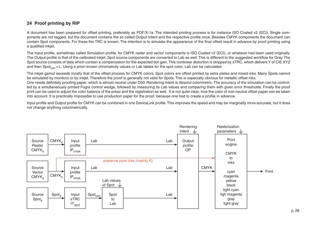
24 Proof printing by RIP
A document has been prepared for offset printing, preferably as PDF/X-�a. The intended printing process is for instance ISO Coated v� (ECI). Single com-ponents are not tagged, but the document contains the so called Output Intent and the respective profile once. Besides CMYK components the document can contain Spot components. For these the TRC is known. The intention is to simulate the appearance of the final offset result in advance by proof printing using a qualified inkjet.
The Input profile, sometimes called Simulation profile, for CMYK raster and vector components is ISO Coated v� (ECI), or whatever had been used originally.The Output profile is that of the calibrated inkjet. Spot source components are converted to Lab as well. This is different to the suggested workflow for Gray. The Spot source consists of data which contain a compensation for the expected dot gain. This nonlinear distortion is stripped by sTRC, which delivers Y of CIE XYZ and then Spotcon = L. Using a priori known chromaticity values or Lab tables for the spot color, Lab can be calculated.
The inkjet gamut exceeds mostly that of the offset process for CMYK colors. Spot colors are offset printed by extra plates and mixed inks. Many Spots cannot be simulated by monitors or by inkjet. Therefore the proof is generally not valid for Spots. This is especially obvious for metallic offset inks.One needs definitely proofing paper, which is almost neutral under D50. Rendering intent is Absolut colorimetric. The accuracy of the simulation can be control-led by a simultaneously printed Fogra control wedge, followed by measuring its Lab values and comparing them with given error thresholds. Finally the proof print can be used to adjust the color balance of the press and the registration as well. It is not quite clear, how the color of non-neutral offset paper can be taken into account. It is practically impossible to use production paper for the proof, because one had to create a profile in advance.
Input profile and Output profile for CMYK can be combined in one DeviceLink profile. This improves the speed and may be marginally more accurate, but it does not change anything colorimetrically.
Lab values of Spot
p. �9
CMYKsSourceRasterCMYKs
Platesetter
CMYK+Spot to
plate
cyanmagenta
yellowblack
spots
Rasterization parameters
SourceVectorCMYKs
CMYKs
SourceSpot
channels
Spots
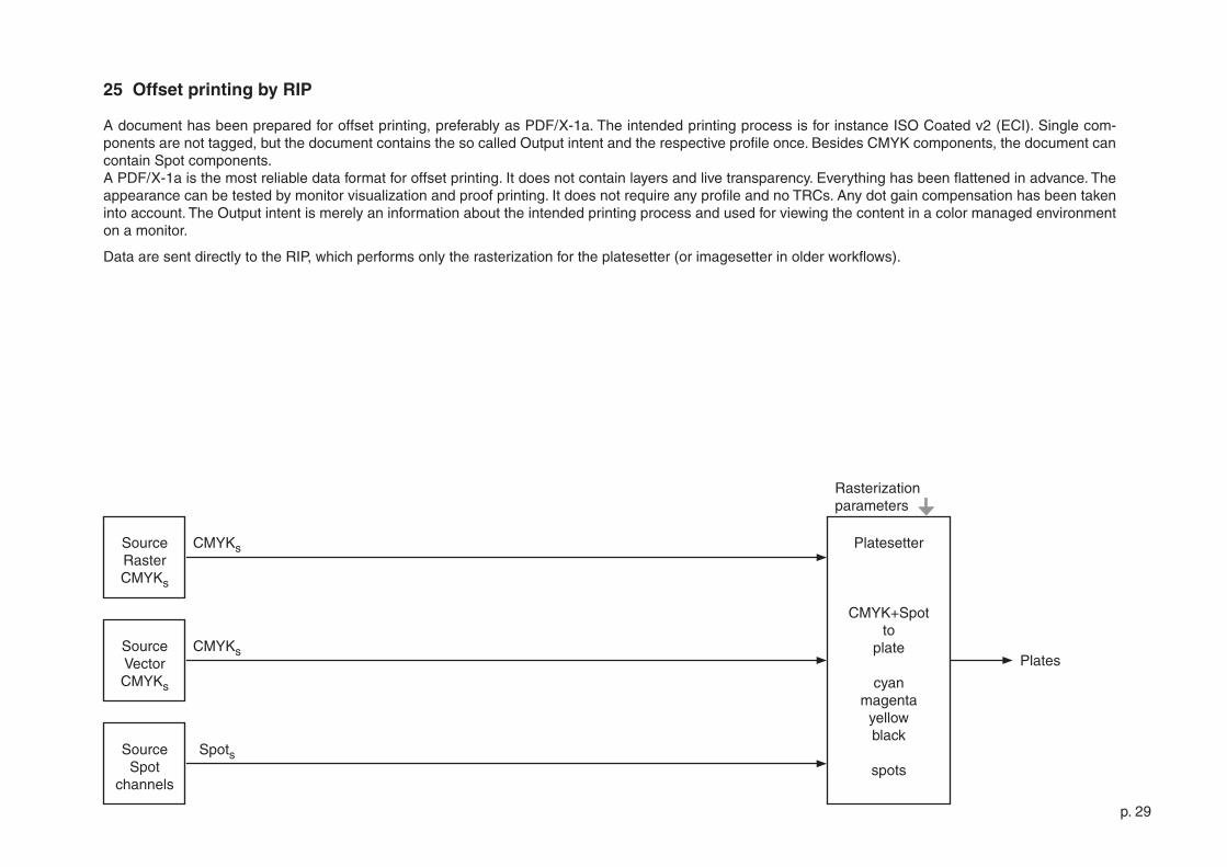
25 Offset printing by RIP
A document has been prepared for offset printing, preferably as PDF/X-�a. The intended printing process is for instance ISO Coated v� (ECI). Single com-ponents are not tagged, but the document contains the so called Output intent and the respective profile once. Besides CMYK components, the document can contain Spot components. A PDF/X-�a is the most reliable data format for offset printing. It does not contain layers and live transparency. Everything has been flattened in advance. The appearance can be tested by monitor visualization and proof printing. It does not require any profile and no TRCs. Any dot gain compensation has been taken into account. The Output intent is merely an information about the intended printing process and used for viewing the content in a color managed environment on a monitor.
Data are sent directly to the RIP, which performs only the rasterization for the platesetter (or imagesetter in older workflows).
Plates
p. 30
[�] G.Wyszecki + W.S.Stiles Color Science John Wiley & Sons, New York ,..., �98�
[�] J.D.Foley + A.van Dam + St.K.Feiner + J.F.Hughes Computer Graphics Addison-Wesley, Reading Massachusetts,...,�993
[3] R.W.G.Hunt Measuring Colour Fountain Press, England, �998
[4] R.W.G.Hunt The Reproduction of Colour, Sixth edition John Wiley & Sons, Chichester, �004
[5] E.J.Giorgianni + Th.E.Madden Digital Color Management Addison-Wesley, Reading Massachusetts ,..., �998
[6] R.S.Berns Billmeyer and Saltzman‘s Principles of Color Technology, Third edition John Wiley & Sons, New York ,..., �000
[7] M.D.Fairchild Color Appearance Models, Second Edition John Wiley & Sons, Chichester, �005
[8] G.Hoffmann CIE (�93�) Color Space http://docs-hoffmann.de/ciexyz�908�000.pdf
[9] G.Hoffmann CIELab Color Space http://docs-hoffmann.de/cielab030��003.pdf
[�0] J.Morovič Color Gamut Mapping John Wiley & Sons, Ltd, Chichester, �008
26 References
p. 3�
[��] Adobe System‘s Implementation of Black Point Compensation http://www.color.org/AdobeBPC.pdf
[��] G.Hoffmann Gamut Visualizations and Out-of-gamut Distances http://docs-hoffmann.de/gamshow�505�009.pdf
[�3] International Color Consortium http://www.color.org [�4] Specification ICC.�:�004-�0 http://www.color.org/icc_specs�.xalter
[�5] Fogra Forschungsgesellschaft Druck e.V. Graphic Technology Research Association http://www.fogra.org/?getlang=en
[�6] European Color Initiative: Offset profiles http://www.eci.org/doku.php?id=en:start
[�7] M.Stokes + M.Anderson + S.Chandrasekar + R.Motta A Standard Default Color Space for the Internet - sRGB http://www.w3.org/graphics/color/sRGB.html �996
[�8] M.Nielsen + M.Stokes The Creation of the sRGB ICC Profile Year unknown, after �998 http://www.srgb.com/c55.pdf (dead link) Search by title or use this link http://tinyurl.com/d7kwym
[�9] ICC Profile Inspector http://www.color.org/profileinspector.xalter
[�0] B.Fraser, C.Murphy, F.Bunting Real World Color Management Peachpit Press, Berkeley,..., �005
[��] A.Sharma Understanding Color Management Thomson Delmar Learning, Clifton Park,..., �004
p. 3�
[��] Dan Margulis Photoshop LAB Color Peachpit Press, �006, �0��
[�3] G.Hoffmann Color Management by ICC Profiles http://docs-hoffmann.de/cmsicc08�0�003.pdf
[�4] G.Hoffmann The gamma question: Nonlinearities in the image processing workflow http://docs-hoffmann.de/gamquest�8�0�00�.pdf
[�5] G.Hoffmann Measuring gamma for monitors http://docs-hoffmann.de/measgamma�00��004.pdf
[�6] G.Hoffmann Hardware monitor calibration (PDF) http://docs-hoffmann.de/caltutor�70900.pdf
[�7] G.Hoffmann Hardware monitor calibration (HTML) http://docs-hoffmann.de/caltutor.html
[�8] H.R.Kang Computational Color Technology SPIE Press, Bellingham, �006
[�9] G.Hoffmann Test pages for all color printers http://docs-hoffmann.de/a3gencolorhigh.pdf
[30] G.Hoffmann Printer resolution test patterns + raster tester http://docs-hoffmann.de/raster�605�003.pdf
[3�] G.Hoffmann Principles of color printing. Color management, rendering, scanning http://docs-hoffmann.de/colrend�90800.pdf
[3�] G.Hoffmann Configuration for a PostScript printer http://docs-hoffmann.de/oki-ps-�808�005.pdf
p. 33
[33] G.Hoffmann CMYK swatch book http://docs-hoffmann.de/swatch�����00�.pdf
[34] G.Hoffmann SPOT swatch book http://docs-hoffmann.de/swatch�603�005.pdf
[35] G.Hoffmann The Digital Munsell / LAB swatch book http://docs-hoffmann.de/munsell�505�009.pdf
[36] Adobe Systems: The Munsell Color System http://web.archive.org/web/�00308�309�0�8/www.adobe.com/support/techguides/color/colormodels/munsell.html Use short URL: http://tinyurl.com/dg9ixx
[37] G.Hoffmann Spectra for Proofing Light http://docs-hoffmann.de/prooflight�809�003.pdf [38] G.Hoffmann PostScript Tutor http://docs-hoffmann.de/pstutor�����00�.pdf
[39] G.Hoffmann PostScript color calculator XYZ, xyY, Lab, RGB http://docs-hoffmann.de/colcalc030��006.pdf
[40] Everything about Color and Computers http://www.efg�.com
[4�] G.Hoffmann Collection of all PDFs http://docs-hoffmann.de/howww4�a.html
[4�] G.Hoffmann RIP Test patterns http://docs-hoffmann.de/riptest0507�0�3 4.6 MB because of ZIP compression and embedded profiles [43] Discussion about the handling of Grayscales in InDesign CS6 http://forums.adobe.com/message/5486833#5486833
p. 34
Gernot Hoffmann
July 08 / �0�3 ... September 09 / �0�4
E-mail: [email protected]
Website: load browser / click here
This document
http://docs-hoffmann.de/cmsflow0307�0�3.pdf