Embed Size (px)
Citation preview

Zenith15/25 GNSS Series - 1 -
Installation Guide © 2017 GeoMax AG, Widnau, Switzerland
GeoMax GNSS
Zenith15/25 Pro Series
Installation Guide
Version 3.00
English

Zenith15/25 GNSS Series - 2 -
Installation Guide © 2017 GeoMax AG, Widnau, Switzerland
Tablet of Contents
1 INTRODUCTION
2 GENERAL PREPARATION
2.1 Copy Zenith15/25 Firmware on MicroSD card
2.2 Battery Charging
3 PREPARATION OF THE GNSS RECEIVER
3.1 Connecting to the PC
3.2 Receiver connection with GeoMax Assistant
3.3 Checking the receiver firmware version
3.4 Changing the UHF radio settings
3.5 Antenna Management
3.6 Installation of licences
3.7 Disconnecting from the PC
4 PREPARATION OF THE HANDHELD
4.1 SETTING UP WINDOWS MOBILE
4.2 Connecting to the PC
4.3 Installation of FieldGenius/ Layout Pro
4.4 Registration of FieldGenius/ Layout Pro
4.5 Connection to the GNSS receiver
5 EQUIPMENT SETUP
5.1 Rover setup
5.2 Base setup
Zenith15/25 GNSS Series - 3 -
Installation Guide © 2017 GeoMax AG, Widnau, Switzerland
1 INTRODUCTION
This guide provides complete step-by-step instructions for preparing the Zenith15 and
Zenith25 Pro GNSS series for measuring work. The instructions cover all the required
installation tasks for the Zenith GNSS receiver, Getac PS336 handheld and FieldGenius/
Layout Pro software.
Only the tasks required for the initial setup of a new Zenith15/25 Pro system are
described in this document. For further information regarding the operation of the
Zenith15/25 Pro components, please refer to the respective User Manuals.
The User Manual for the GNSS receiver is available from the Zenith15/25 Pro CD and also
from the GeoMax Partner Area. The Getac PS336 User Manual can be downloaded from
Getac’s website, at http://en.getac.com/support/downloads.html.

Zenith15/25 GNSS Series - 4 -
Installation Guide © 2017 GeoMax AG, Widnau, Switzerland
2 GENERAL PREPARATION
2.1 COPY ZENITH15/25 FIRMWARE ON MICROSD CARD
Visit GeoMax Downloads to check for the current versions of both System and GNSS
firmware’s. Download the files and store them on the provided MicroSD card in the
SYSTEM folder
2.2 BATTERY CHARGING
Before using the receiver, the included ZBA201 batteries should be charged. Insert a
battery into the ZCH201 charger and plug the adapter into an AC supply. Do not
disconnect from power until the green FULL indicator flashes, indicating that the battery is
fully charged.
The PS336 handheld is supplied in a cardboard box which includes the handheld device,
battery, charging adapter and EU power cable. A suitable AC power cable may need to be
sourced locally to suit country specific plugs. All AC voltages are supported by the adapter.
Insert the supplied battery into the handheld’s battery compartment. Charge the internal
battery with the supplied adapter as shown below. While charging, the circled indicator on the
front of the PS336 glows amber. Do not disconnect from power until the indicator glows
green, indicating that the battery is fully charged.
Zenith15/25 GNSS Series - 5 -
Installation Guide © 2017 GeoMax AG, Widnau, Switzerland
3 PREPARATION OF THE GNSS RECEIVER
3.1 CONNECTING TO THE PC
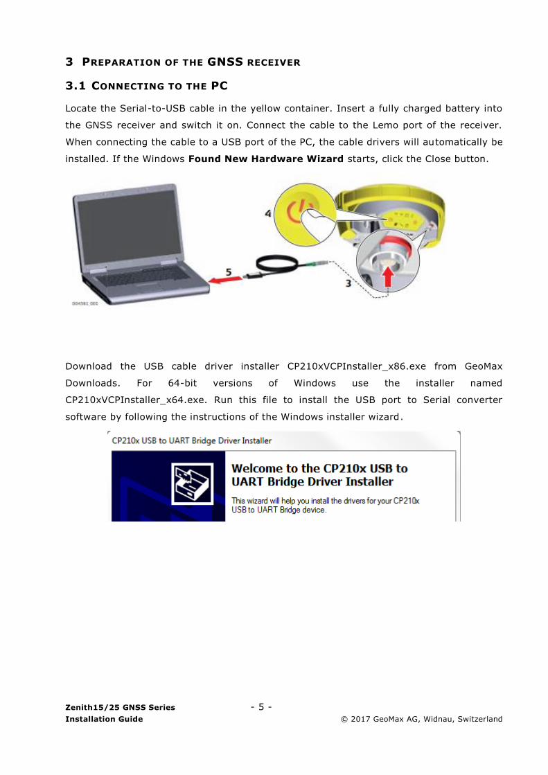
Locate the Serial-to-USB cable in the yellow container. Insert a fully charged battery into
the GNSS receiver and switch it on. Connect the cable to the Lemo port of the receiver.
When connecting the cable to a USB port of the PC, the cable drivers will automatically be
installed. If the Windows Found New Hardware Wizard starts, click the Close button.
Download the USB cable driver installer CP210xVCPInstaller_x86.exe from GeoMax
Downloads. For 64-bit versions of Windows use the installer named
CP210xVCPInstaller_x64.exe. Run this file to install the USB port to Serial converter
software by following the instructions of the Windows installer wizard.
Zenith15/25 GNSS Series - 6 -
Installation Guide © 2017 GeoMax AG, Widnau, Switzerland
3.2 RECEIVER CONNECTION WITH GEOMAX ASSISTANT
Locate the GeoMax Assistant software from GeoMax Downloads in the Zenith15/25 folder
and save to your PC. Run GeoMaxAssistantZenith.exe and following the instructions of
the Windows installer wizard.
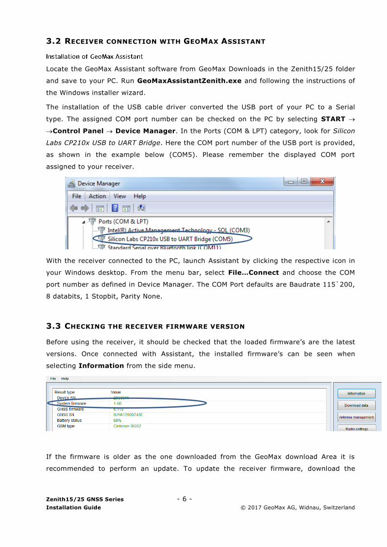
The installation of the USB cable driver converted the USB port of your PC to a Serial
type. The assigned COM port number can be checked on the PC by selecting START
Control Panel Device Manager. In the Ports (COM & LPT) category, look for Silicon
Labs CP210x USB to UART Bridge. Here the COM port number of the USB port is provided,
as shown in the example below (COM5). Please remember the displayed COM port
assigned to your receiver.
With the receiver connected to the PC, launch Assistant by clicking the respective icon in
your Windows desktop. From the menu bar, select File…Connect and choose the COM
port number as defined in Device Manager. The COM Port defaults are Baudrate 115`200,
8 databits, 1 Stopbit, Parity None.
3.3 CHECKING THE RECEIVER FIRMWARE VERSION
Before using the receiver, it should be checked that the loaded firmware’s are the latest
versions. Once connected with Assistant, the installed firmware’s can be seen when
selecting Information from the side menu.
If the firmware is older as the one downloaded from the GeoMax download Area it is
recommended to perform an update. To update the receiver firmware, download the
Zenith15/25 GNSS Series - 7 -
Installation Guide © 2017 GeoMax AG, Widnau, Switzerland
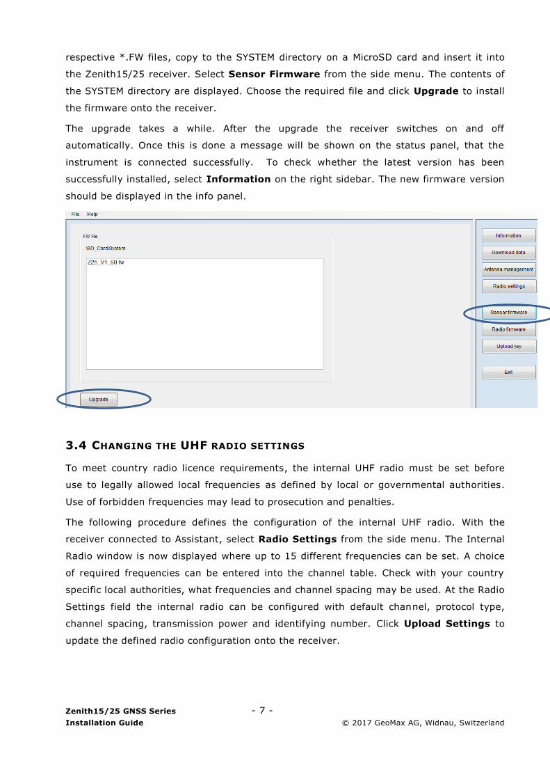
respective *.FW files, copy to the SYSTEM directory on a MicroSD card and insert it into
the Zenith15/25 receiver. Select Sensor Firmware from the side menu. The contents of
the SYSTEM directory are displayed. Choose the required file and click Upgrade to install
the firmware onto the receiver.
The upgrade takes a while. After the upgrade the receiver switches on and off
automatically. Once this is done a message will be shown on the status panel, that the
instrument is connected successfully. To check whether the latest version has been
successfully installed, select Information on the right sidebar. The new firmware version
should be displayed in the info panel.
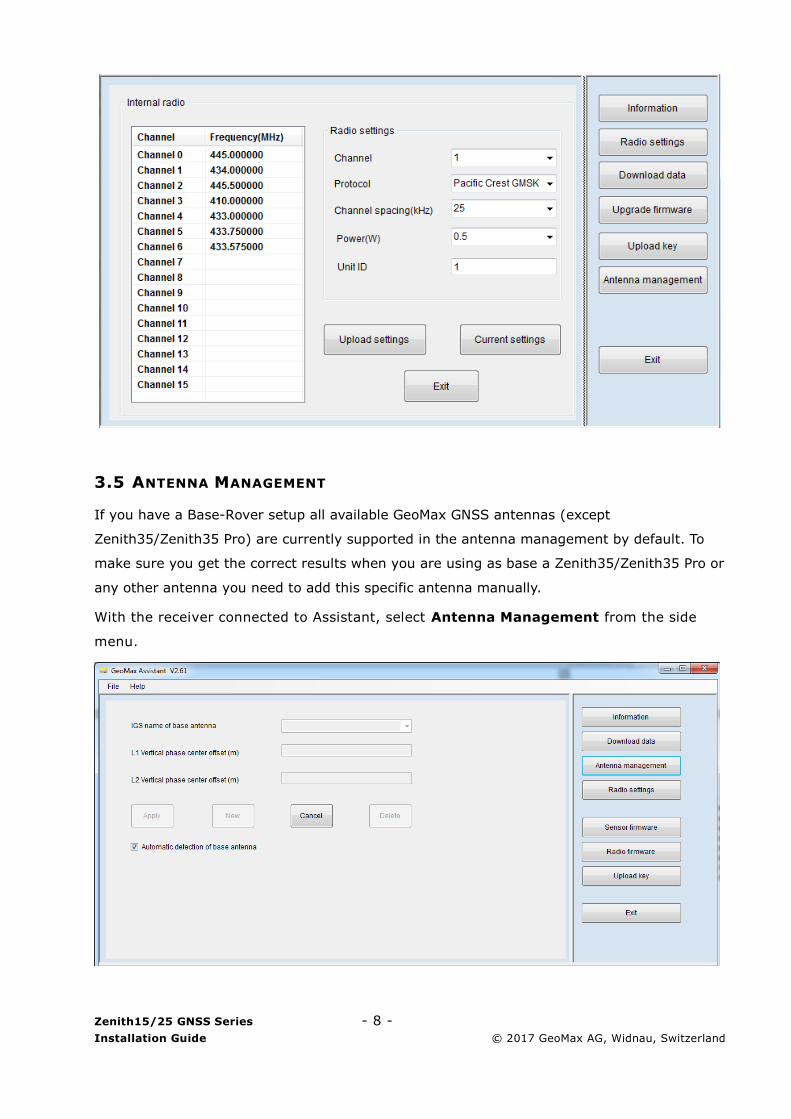
3.4 CHANGING THE UHF RADIO SETTINGS
To meet country radio licence requirements, the internal UHF radio must be set before
use to legally allowed local frequencies as defined by local or governmental authorities.
Use of forbidden frequencies may lead to prosecution and penalties.
The following procedure defines the configuration of the internal UHF radio. With the
receiver connected to Assistant, select Radio Settings from the side menu. The Internal
Radio window is now displayed where up to 15 different frequencies can be set. A choice
of required frequencies can be entered into the channel table. Check with your country
specific local authorities, what frequencies and channel spacing may be used. At the Radio
Settings field the internal radio can be configured with default channel, protocol type,
channel spacing, transmission power and identifying number. Click Upload Settings to
update the defined radio configuration onto the receiver.
Zenith15/25 GNSS Series - 8 -
Installation Guide © 2017 GeoMax AG, Widnau, Switzerland
3.5 ANTENNA MANAGEMENT
If you have a Base-Rover setup all available GeoMax GNSS antennas (except
Zenith35/Zenith35 Pro) are currently supported in the antenna management by default. To
make sure you get the correct results when you are using as base a Zenith35/Zenith35 Pro or
any other antenna you need to add this specific antenna manually.
With the receiver connected to Assistant, select Antenna Management from the side
menu.

Zenith15/25 GNSS Series - 9 -
Installation Guide © 2017 GeoMax AG, Widnau, Switzerland
In order to add new antennas disable the function of the automatic detection of the base
antenna by removing the check mark. Then click New. Enter the IGS name of the base
antenna and the vertical phase center offset for L1 and L2 in meters (m). In order to add the
currently missing GeoMax Zenith35 / Zenith35 Pro, please enter the following parameters.
IGS name for Zenith35/Zenith35 Pro: GMXZENITH35
L1 vertical PCO value in meters: 0.1251
L2 vertical PCO value in meters: 0.1321
Then click Add. The entered antenna is now appearing in the antenna list.
3.6 INSTALLATION OF LICENCES
If optional receiver licenses such as 20Hz output frequency were additionally ordered, they
are not activated before delivery. Therefore when the equipment is first received, the licences
still need to be installed onto the receiver. These options are activated by means of a NovAtel
licence key file that would have been emailed to you at delivery of the Zenith15/25.
The included Auth Code always consists of only one number, even if several options are to be
activated. An example of such a code is
7JKRC3,GNK55W,3ZKMP5,23DC2B,B58JG6,G2SB0G550 where the last part specifies
the included functionality, as follows:
G2SB0G550: GPS tracking at 5Hz
G2SB0GTT0: GPS tracking at 20Hz
D2SB0G550: GPS & GLONASS tracking at 5Hz
Zenith15/25 GNSS Series - 10 -
Installation Guide © 2017 GeoMax AG, Widnau, Switzerland
CDSB0G550: GPS, GLONASS, BeiDou tracking at 5Hz *
D2SB0GTT0: GPS & GLONASS tracking at 20Hz *
CDSB0GTT0: GPS, GLONASS, BeiDou tracking at 20Hz*
* Not applicable to Zenith15
The licence key file can be installed onto the receiver by using GeoMax Assistant. With the
receiver connected to Assistant, select Upload Key from the side menu. Select the key file
(for example L_xxx.key where xxx is the receiver serial number) and click Upload. A
confirmation message will be shown once the option has been activated.
Note:
The MicroSD card must be in the receiver when uploading the key file.
A manual entry of the license key is NOT supported. The files must be uploaded!
3.7 DISCONNECTING FROM THE PC
Once the receiver is completely configured, it can be disconnected from the PC. From the
Assistant menu bar, select File…Disconnect. The USB cable may now be removed and the
Zenith15/25 is ready for use.
4 PREPARATION OF THE HANDHELD
4.1 SETTING UP WINDOWS MOBILE
Once the battery is fully charged or while connected to AC power, press the power button
of the handheld. Follow the steps of the wizard to setup Windows Mobile. The Windows
Mobile software on the supplied Getac PS236 is only available in English language. Microsoft
restricts the installation of alternative languages with this operating system.
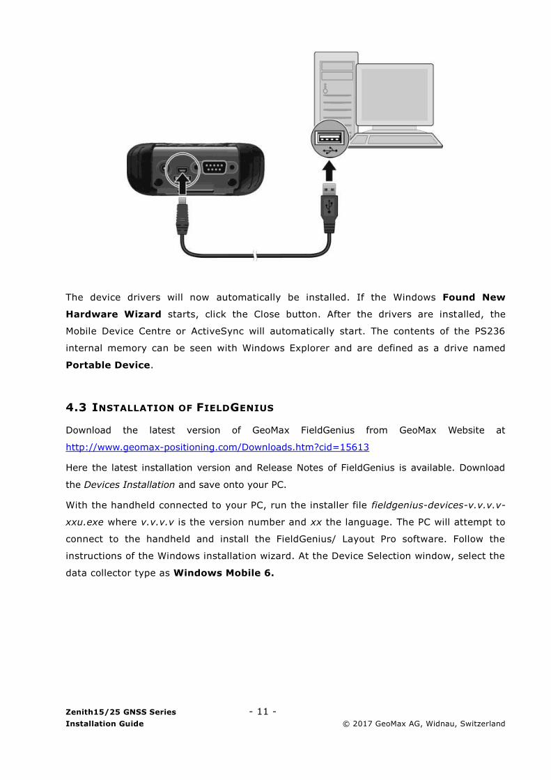
4.2 CONNECTING TO THE PC
To establish communication between the handheld and your PC, the Windows Mobile
Device Centre needs to be installed. For Windows XP the communication software
Microsoft ActiveSync is required. These software’s can be downloaded from Microsoft’s
website. After the software installation, connect the handheld to your PC with the USB
cable supplied with the Getac as shown below.
Zenith15/25 GNSS Series - 11 -
Installation Guide © 2017 GeoMax AG, Widnau, Switzerland
The device drivers will now automatically be installed. If the Windows Found New
Hardware Wizard starts, click the Close button. After the drivers are installed, the
Mobile Device Centre or ActiveSync will automatically start. The contents of the PS236
internal memory can be seen with Windows Explorer and are defined as a drive named
Portable Device.
4.3 INSTALLATION OF FIELDGENIUS
Download the latest version of GeoMax FieldGenius from GeoMax Website at
http://www.geomax-positioning.com/Downloads.htm?cid=15613
Here the latest installation version and Release Notes of FieldGenius is available. Download
the Devices Installation and save onto your PC.
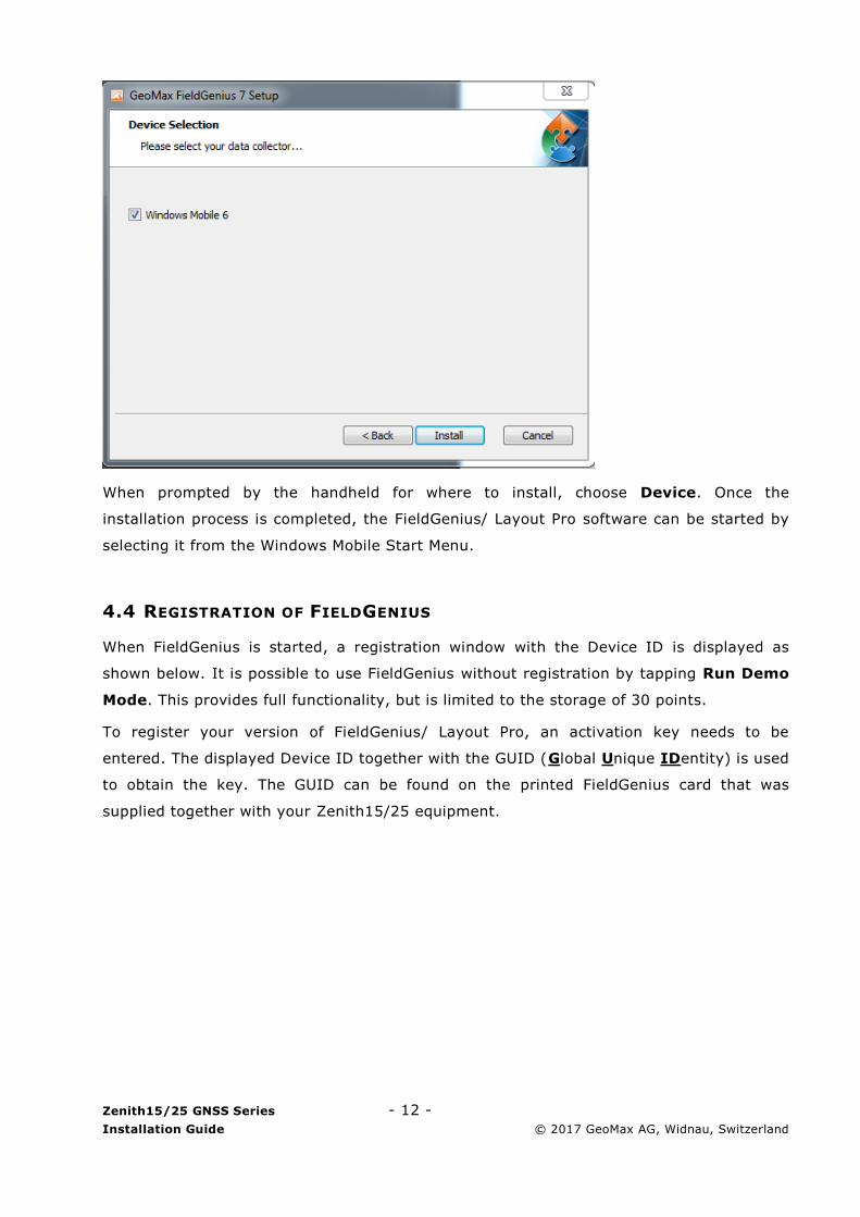
With the handheld connected to your PC, run the installer file fieldgenius-devices-v.v.v.v-
xxu.exe where v.v.v.v is the version number and xx the language. The PC will attempt to
connect to the handheld and install the FieldGenius/ Layout Pro software. Follow the
instructions of the Windows installation wizard. At the Device Selection window, select the
data collector type as Windows Mobile 6.
Zenith15/25 GNSS Series - 12 -
Installation Guide © 2017 GeoMax AG, Widnau, Switzerland
When prompted by the handheld for where to install, choose Device. Once the
installation process is completed, the FieldGenius/ Layout Pro software can be started by
selecting it from the Windows Mobile Start Menu.
4.4 REGISTRATION OF FIELDGENIUS
When FieldGenius is started, a registration window with the Device ID is displayed as
shown below. It is possible to use FieldGenius without registration by tapping Run Demo
Mode. This provides full functionality, but is limited to the storage of 30 points.
To register your version of FieldGenius/ Layout Pro, an activation key needs to be
entered. The displayed Device ID together with the GUID (Global Unique IDentity) is used
to obtain the key. The GUID can be found on the printed FieldGenius card that was
supplied together with your Zenith15/25 equipment.

Zenith15/25 GNSS Series - 13 -
Installation Guide © 2017 GeoMax AG, Widnau, Switzerland
The activation key can be generated by using MicroSurvey’s web portal, at the link
http://microsurveylicenseserver.com/ValidateSerialNumber.aspx. This web portal is
shown in the screenshot below. At the blank serial number field, enter your GUID and
click Submit. At the next screen, enter the Device ID shown on the handheld. The
activation key will then be displayed in the password field. Enter this key into the
handheld at the provided fields and click Apply Key.
Note: Please make certain that the Device ID is entered correctly first time, since an
activation key cannot be generated again with a different ID.

Zenith15/25 GNSS Series - 14 -
Installation Guide © 2017 GeoMax AG, Widnau, Switzerland
4.5 CONNECTION TO THE GNSS RECEIVER
When starting FieldGenius, the Project Manager screen is displayed each time. Create a
new project by tapping the appropriate icon and enter a project name. The onscreen
keyboard can always be accessed by double tapping on the editable field. The screens
that follow are used to set the default settings for this project.
At the Instrument Selection screen that follows, a connection to the receiver can be
made. Ensure that the receiver is switched on and select either GPS Rover or GPS
Reference. In the Instrument Profile window, tap Add and enter a name for your
receiver. Save the name and then tap Edit to configure the profile.
To ensure that measured heights are computed correctly, it is important to define the
receiver type. At the Antenna Height panel, choose the Model as Zenith15/25. The
Measured Height is the default length of the telescopic pole.

Zenith15/25 GNSS Series - 15 -
Installation Guide © 2017 GeoMax AG, Widnau, Switzerland
At the Model & Communication panel, select the Make as GeoMax, Model as
Zenith15/25 and Port as Bluetooth. Tap Bluetooth Search to find all available devices
and choose the required receiver by its serial number. Once a connection has been made,
you will be prompted for a PIN which is 0000.
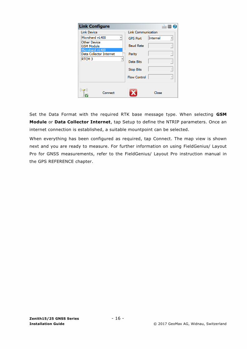
The Link Configure panel is displayed next. In the Link Device field, the following choices
are available:
- Other Device: When connecting an external radio by cable
- GSM Module: For network rover using the internal GSM
- Microhard nL400: When using the internal radio with base or rover mode
- Data Collector Internet: To receive RTK data using the PS236 3G handheld
Zenith15/25 GNSS Series - 16 -
Installation Guide © 2017 GeoMax AG, Widnau, Switzerland
Set the Data Format with the required RTK base message type. When selecting GSM
Module or Data Collector Internet, tap Setup to define the NTRIP parameters. Once an
internet connection is established, a suitable mountpoint can be selected.
When everything has been configured as required, tap Connect. The map view is shown
next and you are ready to measure. For further information on using FieldGenius/ Layout
Pro for GNSS measurements, refer to the FieldGenius/ Layout Pro instruction manual in
the GPS REFERENCE chapter.
Zenith15/25 GNSS Series - 17 -
Installation Guide © 2017 GeoMax AG, Widnau, Switzerland
5 EQUIPMENT SETUP
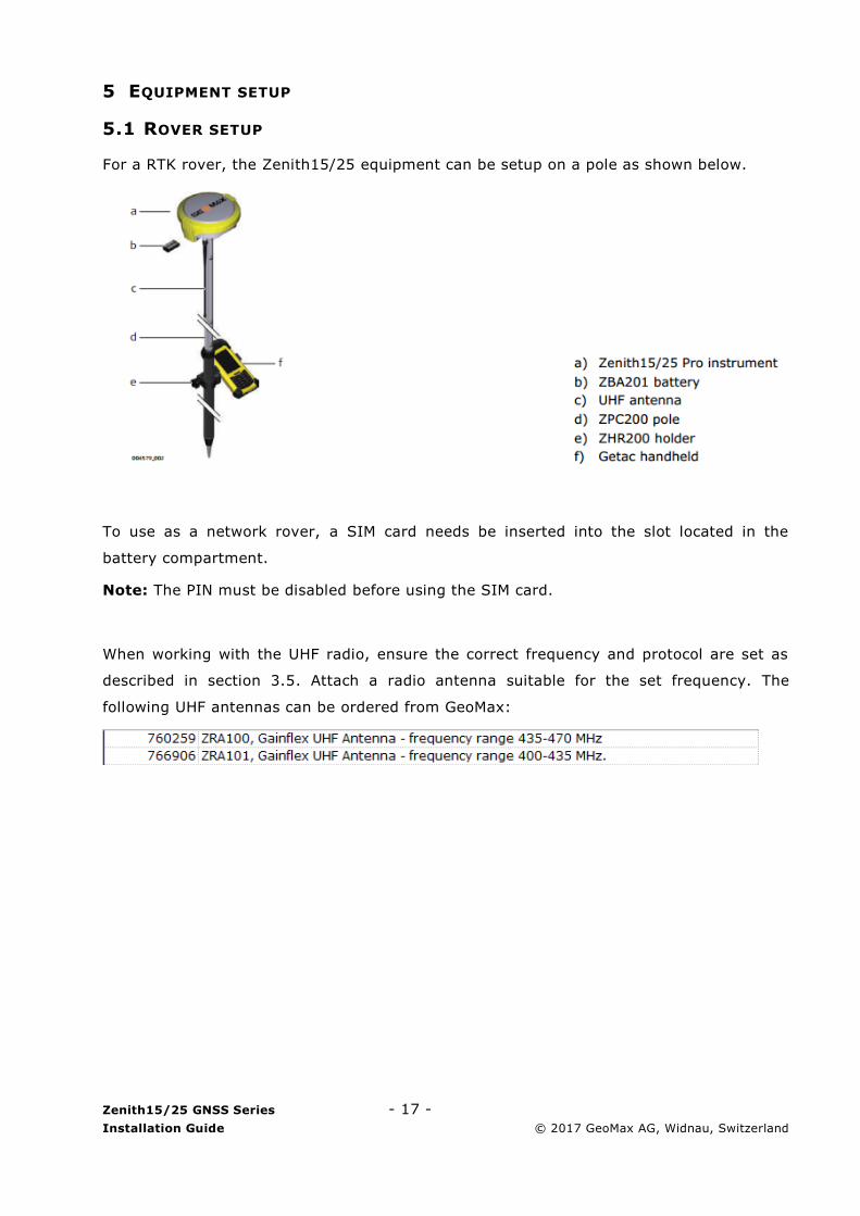
5.1 ROVER SETUP
For a RTK rover, the Zenith15/25 equipment can be setup on a pole as shown below.
To use as a network rover, a SIM card needs be inserted into the slot located in the
battery compartment.
Note: The PIN must be disabled before using the SIM card.
When working with the UHF radio, ensure the correct frequency and protocol are set as
described in section 3.5. Attach a radio antenna suitable for the set frequency. The
following UHF antennas can be ordered from GeoMax:
Zenith15/25 GNSS Series - 18 -
Installation Guide © 2017 GeoMax AG, Widnau, Switzerland
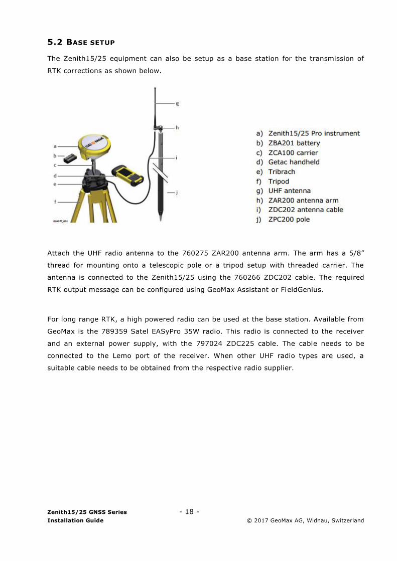
5.2 BASE SETUP
The Zenith15/25 equipment can also be setup as a base station for the transmission of
RTK corrections as shown below.
Attach the UHF radio antenna to the 760275 ZAR200 antenna arm. The arm has a 5/8”
thread for mounting onto a telescopic pole or a tripod setup with threaded carrier. The
antenna is connected to the Zenith15/25 using the 760266 ZDC202 cable. The required
RTK output message can be configured using GeoMax Assistant or FieldGenius.
For long range RTK, a high powered radio can be used at the base station. Available from
GeoMax is the 789359 Satel EASyPro 35W radio. This radio is connected to the receiver
and an external power supply, with the 797024 ZDC225 cable. The cable needs to be
connected to the Lemo port of the receiver. When other UHF radio types are used, a
suitable cable needs to be obtained from the respective radio supplier.