Embed Size (px)
Citation preview

GeoMax Zone60 DG
User Manual
Version 2.0English
Zone60 DG | 2Introduction
IntroductionPurchase Congratulations on the purchase of a GeoMax Rotating Laser product.
This manual contains important safety directions as well as instructions for setting up the product and operating it. Refer to "1 Safety Directions" for further information.Read carefully through the User Manual before you switch on the product.
Product Identification The model and serial number of your product are indicated on the type plate.Always refer to this information when you need to contact your agency or GeoMax authorised service centre.
Validity of this manual This manual applies to the Zone60 DG lasers. Differences between the models are marked and described.
Availabledocumentation
Refer to the following resources for all Zone60 DG documentation/software:• the GeoMax Zone60 DG CD• the GeoMax website: http://www.geomax-positioning.com
Name Description/Format
Zone60 DG Quick Guide
Provides an overview of the product. Intended as a quick reference guide.
Zone60 DG User Manual
All instructions required in order to operate the product to a basic level are contained in the User Manual. Provides an overview of the product together with technical data and safety directions.
-

Table of Contents Zone60 DG | 3
Table of ContentsIn this manual Chapter Page
1 Safety Directions 51.1 General 51.2 Definition of Use 51.3 Limits of Use 61.4 Responsibilities 61.5 Hazards of Use 61.6 Laser Classification 8
1.6.1 General 81.6.2 Zone60 DG 8
1.7 Electromagnetic Compatibility EMC 91.8 FCC Statement, Applicable in U.S. 10
2 Description of the System 122.1 System Components 122.2 Zone60 DG Laser Components 132.3 Case Components 132.4 Setup 14
3 Operation 153.1 User Interface 153.2 Turning the Zone60 DG on and off 153.3 The LCD Display 163.4 Grade Entry 163.5 Axis Identification 183.6 Conversion of Slope Into Percent of Grade 183.7 Alignment of the Axes 183.8 Precise Alignment of the Axes 193.9 Laydown Operation 19
4 ZRC60 Remote Control 204.1 Description of the Remote Control 204.2 Pairing the Zone60 DG with the ZRC60 Remote Control 214.3 Connecting Screens for the Remote Control 21
5 Receivers 225.1 Overview 22
5.1.1 ZRB35 Receiver 225.1.2 ZRP105 Receiver 235.1.3 ZRD105, Digital Receiver 255.1.4 ZRD105B, Digital RF Receiver 25
5.2 Using the ZRD105B Receiver with the Zone60 DG 265.3 Pairing the ZRD105B with the Zone60 DG 26
6 Zone60 DG Menu 276.1 Access and Navigation 276.2 Menu Set 1 286.3 Menu Set 2 316.4 Menu Set 3 33
7 ZRC60 Menu 37
8 Applications 388.1 Setting Forms 388.2 Checking Grades 398.3 Entering Grades 408.4 Beam Catching (Grade Matching) 418.5 Beam Lock (Grade Matching and Monitoring) 42
9 Batteries 439.1 Operating Principles 439.2 Battery for Zone60 DG 43

Zone60 DG | 4Table of Contents
10 Accuracy Adjustment 4510.1 Checking the Level Accuracy 4510.2 Adjusting the Level Accuracy 4610.3 Adjusting the Vertical Accuracy 47
11 Troubleshooting 48
12 Care and Transport 5112.1 Transport 5112.2 Storage 5112.3 Cleaning and Drying 51
13 Technical Data 5213.1 Conformity to National Regulations 5213.2 Dangerous Goods Regulations 5213.3 General Technical Data of the Laser 52
13.3.1 ZRC60 Remote Control 54
Safety Directions Zone60 DG | 5
1 Safety Directions1.1 General
Description The following directions enable the person responsible for the product, and the person who actually uses the equipment, to anticipate and avoid operational hazards.
The person responsible for the product must ensure that all users understand these directions and adhere to them.
About Warning Messages
Warning messages are an essential part of the safety concept of the instrument. They appear wherever hazards or hazardous situations can occur.
Warning messages...• make the user alert about direct and indirect hazards concerning the use of the product.• contain general rules of behaviour.
For the users‘ safety, all safety instructions and safety messages shall be strictly observed and followed! Therefore, the manual must always be available to all persons performing any tasks described here.
DANGER, WARNING, CAUTION and NOTICE are standardised signal words for identifying levels of hazards and risks related to personal injury and property damage. For your safety, it is important to read and fully understand the following table with the different signal words and their definitions! Supplemen-tary safety information symbols may be placed within a warning message as well as supplementary text.
1.2 Definition of Use
Intended use • The product casts a horizontal laser plane or a laser beam for the purpose of alignment.• The laser beam can be detected by means of a laser detector.• Remote control of product.• Data communication with external appliances.
Reasonably foreseeable misuse
• Use of the product without instruction.• Use outside of the intended use and limits.• Disabling safety systems.• Removal of hazard notices.• Opening the product using tools, for example screwdriver, unless this is permitted for certain functions.• Modification or conversion of the product.• Use after misappropriation.• Use of products with obvious damages or defects.• Use with accessories from other manufacturers without the prior explicit approval of GeoMax.• Inadequate safeguards at the working site.• Deliberate dazzling of third parties.• Controlling of machines, moving objects or similar monitoring application without additional control
and safety installations.
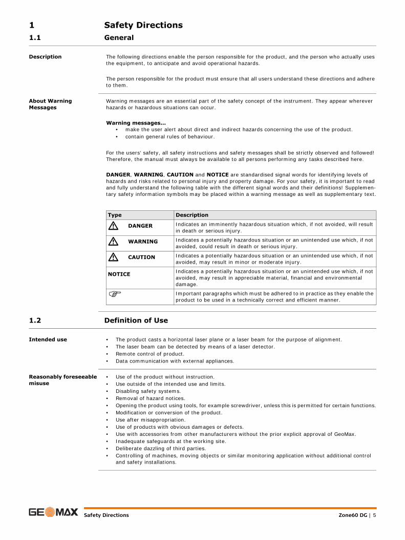
Type Description
� DANGER Indicates an imminently hazardous situation which, if not avoided, will result in death or serious injury.
� WARNING Indicates a potentially hazardous situation or an unintended use which, if not avoided, could result in death or serious injury.
� CAUTION Indicates a potentially hazardous situation or an unintended use which, if not avoided, may result in minor or moderate injury.
NOTICE Indicates a potentially hazardous situation or an unintended use which, if not avoided, may result in appreciable material, financial and environmental damage.
Important paragraphs which must be adhered to in practice as they enable the product to be used in a technically correct and efficient manner.
Zone60 DG | 6Safety Directions
1.3 Limits of Use
Environment Suitable for use in an atmosphere appropriate for permanent human habitation: not suitable for use in aggressive or explosive environments.
� DANGER Local safety authorities and safety experts must be contacted before working in hazardous areas, or close to electrical installations or similar situations by the person in charge of the product.
1.4 Responsibilities
Manufacturer of the product
GeoMax AG, CH-9443 Widnau, hereinafter referred to as GeoMax, is responsible for supplying the product, including the user manual and original accessories, in a safe condition.
Person responsible for the product
The person responsible for the product has the following duties:• To understand the safety instructions on the product and the instructions in the user manual.• To ensure that it is used in accordance with the instructions.• To be familiar with local regulations relating to safety and accident prevention.• To inform GeoMax immediately if the product and the application becomes unsafe.• To ensure that the national laws, regulations and conditions for the operation of the product are
respected.
1.5 Hazards of Use
� CAUTION Watch out for erroneous measurement results if the product has been dropped or has been misused, modi-fied, stored for long periods or transported.Precautions:Periodically carry out test measurements and perform the field adjustments indicated in the user manual, particularly after the product has been subjected to abnormal use as well as before and after important measurements.
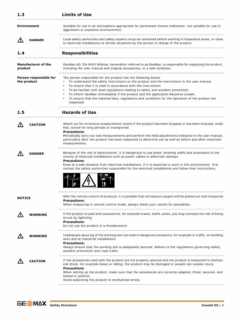
� DANGER Because of the risk of electrocution, it is dangerous to use poles, levelling staffs and extensions in the vicinity of electrical installations such as power cables or electrical railways.Precautions:Keep at a safe distance from electrical installations. If it is essential to work in this environment, first contact the safety authorities responsible for the electrical installations and follow their instructions.
NOTICE With the remote control of products, it is possible that extraneous targets will be picked out and measured.Precautions:When measuring in remote control mode, always check your results for plausibility.
� WARNING If the product is used with accessories, for example masts, staffs, poles, you may increase the risk of being struck by lightning.Precautions:Do not use the product in a thunderstorm.
� WARNING Inadequate securing of the working site can lead to dangerous situations, for example in traffic, on building sites and at industrial installations.Precautions:Always ensure that the working site is adequately secured. Adhere to the regulations governing safety, accident prevention and road traffic.
� CAUTION If the accessories used with the product are not properly secured and the product is subjected to mechan-ical shock, for example blows or falling, the product may be damaged or people can sustain injury.Precautions:When setting up the product, make sure that the accessories are correctly adapted, fitted, secured, and locked in position.Avoid subjecting the product to mechanical stress.
Safety Directions Zone60 DG | 7
� CAUTION During the transport, shipping or disposal of batteries it is possible for inappropriate mechanical influences to constitute a fire hazard.Precautions:Before shipping the product or disposing of it, discharge the batteries by running the product until they are flat.When transporting or shipping batteries, the person in charge of the product must ensure that the appli-cable national and international rules and regulations are observed. Before transportation or shipping contact your local passenger or freight transport company.
� WARNING During dynamic applications, for example stakeout procedures there is a danger of accidents occurring if the user does not pay attention to the environmental conditions around, for example obstacles, excava-tions or traffic.Precautions:The person responsible for the product must make all users fully aware of the existing dangers.
� WARNING If you open the product, either of the following actions may cause you to receive an electric shock.• Touching live components• Using the product after incorrect attempts were made to carry out repairsPrecautions:Do not open the product. Only GeoMax authorised service centres are entitled to repair these products.
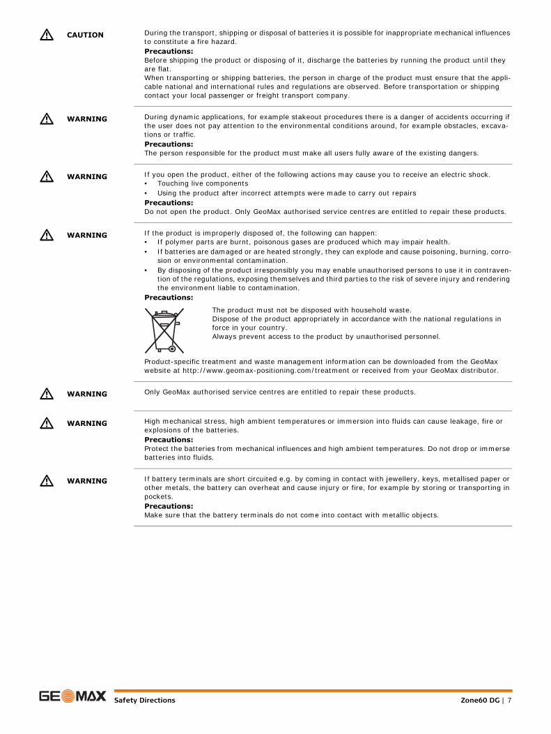
� WARNING If the product is improperly disposed of, the following can happen:• If polymer parts are burnt, poisonous gases are produced which may impair health.• If batteries are damaged or are heated strongly, they can explode and cause poisoning, burning, corro-
sion or environmental contamination.• By disposing of the product irresponsibly you may enable unauthorised persons to use it in contraven-
tion of the regulations, exposing themselves and third parties to the risk of severe injury and rendering the environment liable to contamination.
Precautions:
Product-specific treatment and waste management information can be downloaded from the GeoMax website at http://www.geomax-positioning.com/treatment or received from your GeoMax distributor.
� WARNING Only GeoMax authorised service centres are entitled to repair these products.
� WARNING High mechanical stress, high ambient temperatures or immersion into fluids can cause leakage, fire or explosions of the batteries.Precautions:Protect the batteries from mechanical influences and high ambient temperatures. Do not drop or immerse batteries into fluids.
� WARNING If battery terminals are short circuited e.g. by coming in contact with jewellery, keys, metallised paper or other metals, the battery can overheat and cause injury or fire, for example by storing or transporting in pockets.Precautions:Make sure that the battery terminals do not come into contact with metallic objects.
The product must not be disposed with household waste.Dispose of the product appropriately in accordance with the national regulations in force in your country.Always prevent access to the product by unauthorised personnel.

Zone60 DG | 8Safety Directions
1.6 Laser Classification
1.6.1 General
General The following chapters provide instructions and training information about laser safety according to inter-national standard IEC 60825-1 (2014-05) and technical report IEC TR 60825-14 (2004-02). The informa-tion enables the person responsible for the product and the person who actually uses the equipment, to anticipate and avoid operational hazards.
1.6.2 Zone60 DG
General The rotating laser built into the product produces a visible laser beam which emerges from the rotating head.
The laser product described in this section is classified as laser class 1 in accordance with:• IEC 60825-1 (2014-05): “Safety of laser products”
These products are safe for momentary exposures but can be hazardous for deliberate staring into the beam. The beam may cause dazzle, flash-blindness and after-images, particularly under low ambient light conditions.Zone60 DG:
Labelling
According to IEC TR 60825-14 (2004-02), products classified as laser class 1, class 2 and class 3R do not require:
• laser safety officer involvement,• protective clothes and eyewear,• special warning signs in the laser working area
if used and operated as defined in this User Manual due to the low eye hazard level.
National laws and local regulations could impose more stringent instructions for the safe use of lasers than IEC 60825-1 (2014-05) and IEC TR 60825-14 (2004-02).
Description Value
Maximum average radiant output power 0.4 mW / 2.2 mW
Pulse duration (effective) 500 ms / 2.9 ms, 1.4 ms
Pulse repetition frequency 1 Hz / 5 Hz, 10 Hz
Beam divergence 0.2 mrad
Wavelength 635 nm
a) Laser beam011205_001
aa
Safety Directions Zone60 DG | 9
1.7 Electromagnetic Compatibility EMC
Description The term Electromagnetic Compatibility is taken to mean the capability of the product to function smoothly in an environment where electromagnetic radiation and electrostatic discharges are present, and without causing electromagnetic disturbances to other equipment.
� WARNING Electromagnetic radiation can cause disturbances in other equipment.
Although the product meets the strict regulations and standards which are in force in this respect, GeoMax cannot completely exclude the possibility that other equipment may be disturbed.
� CAUTION There is a risk that disturbances may be caused in other equipment if the product is used with accessories from other manufacturers, for example field computers, personal computers or other electronic equip-ment, non-standard cables or external batteries.Precautions:Use only the equipment and accessories recommended by GeoMax. When combined with the product, they meet the strict requirements stipulated by the guidelines and standards. When using computers or other electronic equipment, pay attention to the information about electromagnetic compatibility provided by the manufacturer.
� CAUTION Disturbances caused by electromagnetic radiation can result in erroneous measurements.Although the product meets the strict regulations and standards which are in force in this respect, GeoMax cannot completely exclude the possibility that the product may be disturbed by intense electromagnetic radiation, for example, near radio transmitters, two-way radios or diesel generators.Precautions:Check the plausibility of results obtained under these conditions.
� CAUTION If the product is operated with connecting cables attached at only one of their two ends, for example external supply cables, interface cables, the permitted level of electromagnetic radiation may be exceeded and the correct functioning of other products may be impaired. Precautions:While the product is in use, connecting cables, for example product to external battery, product to computer, must be connected at both ends.
Radios or Digital Cellular Phones
Use of product with radio or digital cellular phone devices:
� WARNING Electromagnetic fields can cause disturbances in other equipment, in installations, in medical devices, for example pacemakers or hearing aids and in aircraft. It can also affect humans and animals.Precautions:Although the product meets the strict regulations and standards which are in force in this respect, GeoMax cannot completely exclude the possibility that other equipment can be disturbed or that humans or animals can be affected.
• Do not operate the product with radio or digital cellular phone devices in the vicinity of filling stations or chemical installations, or in other areas where an explosion hazard exists.
• Do not operate the product with radio or digital cellular phone devices near to medical equipment.• Do not operate the product with radio or digital cellular phone devices in aircraft.

Zone60 DG | 10Safety Directions
1.8 FCC Statement, Applicable in U.S.
The greyed paragraph below is only applicable for products without radio.
� WARNING
� WARNING Changes or modifications not expressly approved by GeoMax for compliance could void the user's authority to operate the equipment.
Labelling Zone60 DG
Labelling receiver
Labelling receiver
This equipment has been tested and found to comply with the limits for a Class B digital device, pursuant to part 15 of the FCC rules.These limits are designed to provide reasonable protection against harmful interference in a residential installation.This equipment generates, uses and can radiate radio frequency energy and, if not installed and used in accordance with the instructions, may cause harmful interference to radio communications. However, there is no guarantee that interference will not occur in a particular installation.If this equipment does cause harmful interference to radio or television reception, which can be deter-mined by turning the equipment off and on, the user is encouraged to try to correct the interference by one or more of the following measures:• Reorient or relocate the receiving antenna.• Increase the separation between the equipment and the receiver.• Connect the equipment into an outlet on a circuit different from that to which the receiver is connected.• Consult the dealer or an experienced radio/TV technician for help.
Complies with FDA performance standards forlaser products except for deviations pursuant to
Laser Notice Nr. 50 July 24, 2007
This device complies with part 15 of the FCCRules. Operation is subject to the following
two conditions: (1) This device may notcause harmful interference, and (2) This
device must accept any interferencereceived, including interference that
may cause undesired operation.
GeoMax AGCH-9443 Widnau
Serial Number: YWWY60DG
Y W W Y 8 7 0 2 5 0 0
Class 1 Laser - IEC 60825-1:2014
Type: Zone60 DG Power: 8.4V / 0.5A / Art.No.: 835240Made in China / Manufactured: MM/YYYY
Contains FCC ID: RFD-CT300 IC: 3177A-CT300
011206_001
ZRB35:
This device complies with part 15 of the FCC Rules.Operation is subject to the following two conditions:(1) This device may not cause harmful interference,and (2) This device must accept any interferencereceived, including interference that may causeundesired operation.
Type: ZRB35Art.No.: 835246Power: 9V / 0.2AGeoMax AGCH-9443 WidnauMade in ChinaManufactured: MM/YYYYS.No.: 1234567
011178_001
ZRP105:
This device complies with part 15 of the FCC Rules.Operation is subject to the following two conditions:(1) This device may not cause harmful interference, and(2) This device must accept any interference received, including interference that may cause undesired operation.
GeoMax AGCH-9443 Widnau
Type: ZRP105Art.No.: 835247Power: 3V / 60mAMade in ChinaManufactured: MM/YYYYS.No.: 1234567
011177_001

Safety Directions Zone60 DG | 11
Labelling receiver
Labelling receiver
Labelling ZRC60
ZRD105:
This device complies with part 15 of the FCC Rules.Operation is subject to the following two conditions:(1) This device may not cause harmful interference, and(2) This device must accept any interference received, including interference that may cause undesired operation.
GeoMax AGCH-9443 Widnau
Type: ZRD105Art.No.: 835248Power: 3V / 60mAMade in ChinaManufactured: MM/YYYYS.No.: 1234567
011243_001
ZRD105B:
This device complies with part 15 of the FCC Rules.Operation is subject to the following two conditions:(1) This device may not cause harmful interference, and(2) This device must accept any interference received, including interference that may cause undesired operation.
GeoMax AGCH-9443 Widnau
Model: ZRD105BArt.No.: 855671Power: 3V / 60mAMade in ChinaManufactured: MM/YYYYS.No.: 1234567
FCC ID:RFD ID-CT100 IC:3177A-CT100
014299_001
ZRC60
This device complies with part 15 of the FCC Rules. Operation is subjectto the following two conditions: (1) This device may not cause harmfulinterference, and (2) this device must accept any interference received,including interference that may cause undesired operation.
Type: ZRC60Power : 3V / 100mAArt.No.: 835245Made in ChinaGeoMax AGCH-9443 WidnauContains FCC ID: RFD-CT300 IC ID: 3177A-CT300
011208_001

Zone60 DG | 12Description of the System
2 Description of the System2.1 System Components
General description The Zone60 DG is a laser tool for general construction, levelling and slope applications such as:• Setting forms,• Levelling to grade,• Controlling depths for excavations.If set up within the self-levelling range, the Zone60 DG automatically levels to create an accurate hori-zontal, vertical or sloped plane of laser light.Once the Zone60 DG has levelled, the head starts rotating and the Zone60 DG is ready for use. 30 seconds after the Zone60 DG has completed the levelling, the H.I.Alert system becomes active and protects the Zone60 DG against changes in elevation caused by movement of the tripod to ensure accurate work.
Area of application
Available system components
The delivered components depend on the package ordered.
The Zone60 DG is a dual grade laser; it produces an accurate plane of laser light for applications which require level (1), single slope (2) or dual slope (3).1
23
011209_003 ZRP105ZRD105B
Zone60 DG
Li-Ion/Alkaline
ZRC60
ZRD105
ZRB35
ZRD105B

Description of the System Zone60 DG | 13
2.2 Zone60 DG Laser Components
Zone60 DG laser compo-nents
2.3 Case Components
Case components
a) Plate for optional scopeb) Carry Handlec) LCD Displayd) Control Panele) Battery compartmentf) Charge LED (for Li-Ion battery pack)011232_001
a
b
d
ef
c
a) Zone60 DG laserb) Charger (for Li-Ion versions only)c) Li-Ion battery pack or Alkaline battery packd) 4 x D-cell battery (for alkaline versions only)e) 2x AA-cell batteryf) Optional scope assembly g) User Manual/CD h) Receiver mounted on the bracketi) Second receiver (can be purchased separately)j) ZRC60 remote control
011213_001
a
bcd
g
h
ief j
Zone60 DG | 14Description of the System
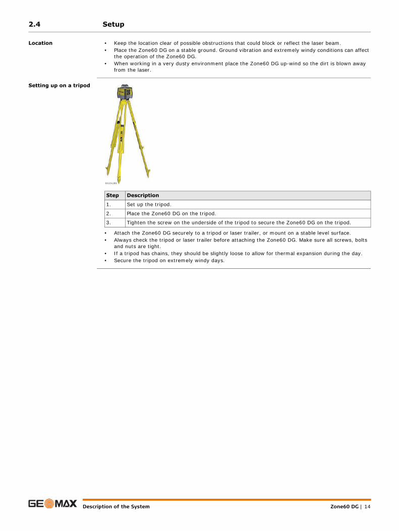
2.4 Setup
Location • Keep the location clear of possible obstructions that could block or reflect the laser beam.• Place the Zone60 DG on a stable ground. Ground vibration and extremely windy conditions can affect
the operation of the Zone60 DG.• When working in a very dusty environment place the Zone60 DG up-wind so the dirt is blown away
from the laser.
Setting up on a tripod
• Attach the Zone60 DG securely to a tripod or laser trailer, or mount on a stable level surface.• Always check the tripod or laser trailer before attaching the Zone60 DG. Make sure all screws, bolts
and nuts are tight.• If a tripod has chains, they should be slightly loose to allow for thermal expansion during the day.• Secure the tripod on extremely windy days.
Step Description
1. Set up the tripod.
2. Place the Zone60 DG on the tripod.
3. Tighten the screw on the underside of the tripod to secure the Zone60 DG on the tripod.
011214_001

Operation Zone60 DG | 15
3 Operation3.1 User Interface
Overview
Description
3.2 Turning the Zone60 DG on and off
Turning on and off Press the Power Button to turn on or off the Zone60 DG.After turning on: • The LCD display turns on and displays the current status of the Zone60 DG.• If set up within the +/-6° self-levelling range (horizontal or vertical), the Zone60 DG automatically
levels to create an accurate horizontal plane of laser light.• Once levelled, the head starts rotating and Zone60 DG is ready for use.• If activated, the H.I.Alert system becomes active 30 seconds after completing the levelling. The
H.I.Alert system protects the laser against changes in elevation caused by movement or settling of the tripod.
• The self-levelling system and the H.I.Alert function continue to monitor the position of the laser beam to ensure consistent and accurate work.
a) LCD displayb) Up and down arrow buttonsc) Left and right arrow buttonsd) Status LED e) Power button f) Grade button
a
b
c
e
d
f
011215_001
LCD display Displays all required user information.
Grade button Press to start grade entry mode.
Left and right arrow buttons Press to display and move the cursor for grade entry.Press both simultaneously to enter the Zone60 DG menu.
Up and down arrow buttons Press to change the grade displayed.Press both simultaneously to reset the grade value to zero.
Power button Press to turn on or off the Zone60 DG.
Status LED Indicates the level status of the Zone60 DG.
Zone60 DG | 16Operation
3.3 The LCD Display
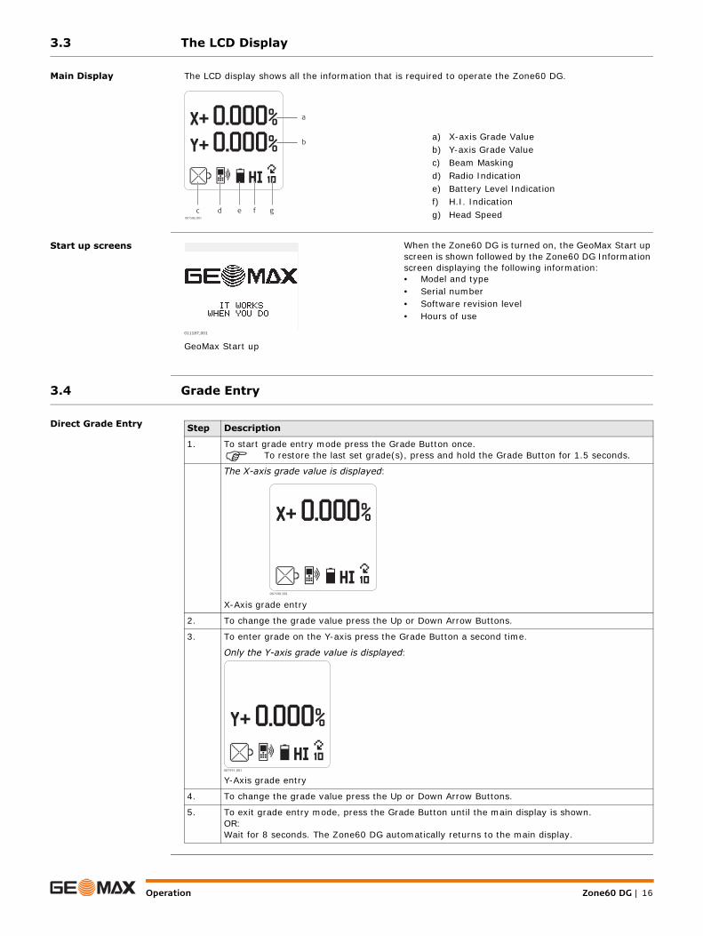
Main Display The LCD display shows all the information that is required to operate the Zone60 DG.
Start up screens
3.4 Grade Entry
Direct Grade Entry
a) X-axis Grade Valueb) Y-axis Grade Valuec) Beam Maskingd) Radio Indicatione) Battery Level Indicationf) H.I. Indicationg) Head Speed007586_001
c d e f g
a
b
When the Zone60 DG is turned on, the GeoMax Start up screen is shown followed by the Zone60 DG Information screen displaying the following information:• Model and type• Serial number• Software revision level• Hours of use
GeoMax Start up011187_001
Step Description
1. To start grade entry mode press the Grade Button once.
To restore the last set grade(s), press and hold the Grade Button for 1.5 seconds.
The X-axis grade value is displayed:
X-Axis grade entry
2. To change the grade value press the Up or Down Arrow Buttons.
3. To enter grade on the Y-axis press the Grade Button a second time.
Only the Y-axis grade value is displayed:
Y-Axis grade entry
4. To change the grade value press the Up or Down Arrow Buttons.
5. To exit grade entry mode, press the Grade Button until the main display is shown.OR:Wait for 8 seconds. The Zone60 DG automatically returns to the main display.
007590_001
007591_001

Operation Zone60 DG | 17
Grade Entry by Digit While in grade entry mode, you can easily change the plus/minus sign or individual digits.
Reset Grade Value to Zero
While in grade entry mode, you can quickly change the grade value back to zero by pressing the Up and Down Arrow Buttons simultaneously.
Grade Capability The Zone60 DG can have up to 10.00% grade simultaneously in both the X and Y axes or up to 15.00% grade in one axis.Entering grades above 10.00% in one axis is only possible if the cross axis grade is ±3% or lower.
If you try to enter grades greater than 3% or 10%, a notice appears on the screen when you press the button.
Grade Swap The grade in the X and Y axes can easily be swapped from positive to negative by changing the plus/minus sign in grade entry mode. Refer to Grade Entry by Digit.A typical application for this feature is road building. Example: The Zone60 DG is set up on the crown of the road and one axis is aligned to the centreline. In order to make the cross axis grade fall to the right or left hand side, simply change the plus/minus sign on the display.
Step Description
Press the Grade Button to enter the grade entry mode.
1. Press the Left or Right Arrow Buttons to create a cursor. The cursor always appears on the plus/minus sign.
2. Press the Up or Down Arrow Buttons to change the plus/minus sign.
3. Press the Left or Right Arrow Buttons to move the cursor.
4. Press the Up or Down Arrow Buttons to change a digit.
5. To exit grade entry mode, press the Grade Button until the main display is shown.OR:Wait for 8 seconds. The Zone60 DG automatically returns to the main display.
007593_001
007594_001
X > 3.000% X > 10.00%007595_001 007596_001

Zone60 DG | 18Operation
3.5 Axis Identification
Axis identification When entering grade, it is important to know the correct direction in which the grade is being entered.Refer to the following illustration to identify the correct directions of the axes.
3.6 Conversion of Slope Into Percent of Grade
Conversion of slope Slope: The change in elevation per unit of measure (foot, metre, etc.)Percent of Grade: The change in elevation per 100 units of measure (feet, metre, etc.)Calculating percent of grade from slope: [Slope] x 100 = [Percent of Grade]Example:
3.7 Alignment of the Axes
Aligning X- and Y-axis After the desired grade is correctly set in the display, align the X- and Y-axis to the jobsite.
Ensure that the bubble of the circular level is positioned near the centre of the circle for maximum self-levelling capability.
Ensure that the Zone60 DG is properly positioned over a control point.The direction of the X-Axis is seen from the front of the Zone60 DG, sighting over the top of the Zone60 DG.
Rotate the Zone60 DG slightly until the alignment marks are aligned with your second control point.Once the Zone60 DG is aligned, you can start working.
X+ Y+
Y— X—
011219 001
Slope = 0.0059Conversion = 0.0059 x 100Percent of Grade = 0.590%
011220_001

Operation Zone60 DG | 19
3.8 Precise Alignment of the Axes
Precisely aligning X- and Y-axis
Under most conditions, the raised alignment marks on the top of the Zone60 DG are adequate for align-ment of the axes. For a more precise alignment, you can use the following procedure.Objective of a precise alignment: • To establish Point A on the Y-axis as a reference and take an elevation reading.• To enter grade into the X-axis and then adjust the position of the laser until the original elevation at
Point A is again found.
3.9 Laydown Operation
Vertical plane of laser light
You can use the Zone60 DG in laying down position to create a vertical plane for layout and alignment jobs.
Zone60 DG Laying Down Screen
Step Description
1. With 0.000% grade in both axes, set up the Zone60 DG directly over a grade stake and roughly align the Y-axis to a second grade stake (Point A).
2. Take an elevation reading at Point A using the receiver and a survey rod.
3. Enter +5.000% grade into the X-axis. When grade is entered into the X-axis, the Y-axis acts like a hinge or fulcrum.
4. With +5.000% in the X-axis, take a second reading at Point A.
5. Alignment:• If the second reading is equal to the first reading, the X-axis is aligned correctly.• If the second reading is greater than the first reading, rotate the Zone60 DG clockwise (to
the right) until the two readings are equal.• If the second reading is less than the first reading, rotate the Zone60 DG counter-clockwise
(to the left) until the two readings are equal.
Sighting Scope - An optional sighting scope is available for the Zone60 DG which improves the axis alignment for second day setups. It is recommended that you first perform the precise alignment procedure, and then adjust the scope to these axes.
007597_001
Zone60 DG | 20ZRC60 Remote Control
4 ZRC60 Remote Control4.1 Description of the Remote Control
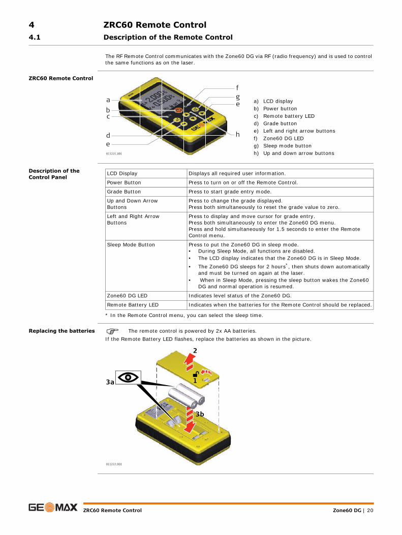
The RF Remote Control communicates with the Zone60 DG via RF (radio frequency) and is used to control the same functions as on the laser.
ZRC60 Remote Control
Description of the Control Panel
* In the Remote Control menu, you can select the sleep time.
Replacing the batteries The remote control is powered by 2x AA batteries.If the Remote Battery LED flashes, replace the batteries as shown in the picture.
a) LCD displayb) Power buttonc) Remote battery LEDd) Grade buttone) Left and right arrow buttonsf) Zone60 DG LEDg) Sleep mode buttonh) Up and down arrow buttons011221_001
abc
de
fg
h
e
LCD Display Displays all required user information.
Power Button Press to turn on or off the Remote Control.
Grade Button Press to start grade entry mode.
Up and Down Arrow Buttons
Press to change the grade displayed.Press both simultaneously to reset the grade value to zero.
Left and Right Arrow Buttons
Press to display and move cursor for grade entry.Press both simultaneously to enter the Zone60 DG menu.Press and hold simultaneously for 1.5 seconds to enter the Remote Control menu.
Sleep Mode Button Press to put the Zone60 DG in sleep mode.• During Sleep Mode, all functions are disabled.• The LCD display indicates that the Zone60 DG is in Sleep Mode.• The Zone60 DG sleeps for 2 hours*, then shuts down automatically
and must be turned on again at the laser.• When in Sleep Mode, pressing the sleep button wakes the Zone60
DG and normal operation is resumed.
Zone60 DG LED Indicates level status of the Zone60 DG.
Remote Battery LED Indicates when the batteries for the Remote Control should be replaced.
011222_001
1
2
3a
3b
ZRC60 Remote Control Zone60 DG | 21
4.2 Pairing the Zone60 DG with the ZRC60 Remote Control
Pairing step-by-step The Zone60 DG and the ZRC60 Remote Control include radio devices that allow you to activate the func-tions on the Zone60 DG remotely up to 300 m (1000’) from the Zone60 DG. Before using the RF features, the Zone60 DG and the Remote Control must be paired together to be able to communicate with each other.
4.3 Connecting Screens for the Remote Control
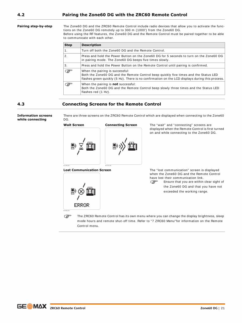
Information screens while connecting
There are three screens on the ZRC60 Remote Control which are displayed when connecting to the Zone60 DG.
The ZRC60 Remote Control has its own menu where you can change the display brightness, sleep mode hours and remote shut-off time. Refer to "7 ZRC60 Menu"for information on the Remote Control menu.
Step Description
1. Turn off both the Zone60 DG and the Remote Control.
2. Press and hold the Power Button on the Zone60 DG for 5 seconds to turn on the Zone60 DG in pairing mode. The Zone60 DG beeps five times slowly.
3. Press and hold the Power Button on the Remote Control until pairing is confirmed.
When the pairing is successful: Both the Zone60 DG and the Remote Control beep quickly five times and the Status LED flashes green quickly (5 Hz). There is no confirmation on the LCD displays during this process.
When the pairing is not successful:Both the Zone60 DG and the Remote Control beep slowly three times and the Status LED flashes red (1 Hz).
Wait Screen Connecting Screen The “wait” and “connecting” screens are displayed when the Remote Control is first turned on and while connecting to the Zone60 DG.
Lost Communication Screen The “lost communication” screen is displayed when the Zone60 DG and the Remote Control have lost their communication link.
Ensure that you are within clear sight of the Zone60 DG and that you have not exceeded the working range.
007598_001 007599_001
007600_001

Zone60 DG | 22Receivers
5 Receivers5.1 Overview
Description The Zone60 DG is sold with either the ZRB35, ZRP105, ZRD105 or the ZRD105B receiver. The ZRD105B receiver enhances the performance of the Zone60 DG with automatic Beam Catching and monitoring.
5.1.1 ZRB35 Receiver
Instrument components part 1 of 2
Instrument components part 2 of 2
a) Level vialb) Keypadc) On-graded) Laser Reception windowe) LCD windowf) Audio Speaker
Component Description
Level vial Aids to keep the rod plumb when taking readings.
Keypad Power, accuracy and volume functions.
On-grade Indicates the on-grade position of the laser.
Laser Reception window
Detects the laser beam. The reception windows must be directed towards the laser.
LCD window Front and rear LCD arrow indicate the detector’s position.
Audio Speaker Indicates the detector’s position:• High - Fast beeping• On-grade - Solid tone• Low - Slow beeping
011190_001
a
b
c
def
a) Bracket Mounting Holeb) Offset notchc) Battery doord) Serial number labele) Product label
Component Description
Bracket Mounting Hole
Location to attach the receiver bracket for normal operation.
Offset notch Use to transfer reference marks. The notch is 45 mm (1.75") below to top of the detector.
Battery door Access to the battery compartment.
005666_001
a
b
c
de

Receivers Zone60 DG | 23
Description of the buttons
5.1.2 ZRP105 Receiver
Instrument components part 1 of 2
a) Audiob) Bandwidthc) Power
Button Function
Audio Press to change the audio output.
Bandwidth Press to change detection bandwidth.
Power Press once to turn on the Receiver.
011192_001
ab
c
a) Level vialb) Audio Speakerc) LCD windowd) LEDse) Laser Reception windowf) On-gradeg) Keypad
Component Description
Level vial Aids to keep the rod plumb when taking readings.
Audio Speaker Indicates the detector’s position:• High - Fast beeping• On-grade - Solid tone• Low - Slow beeping
LCD window Front and rear LCD arrow indicate the detector’s position.
LEDs Display the relative position of the laser beam. Three channel indication:• High - Red• On-grade - Green• Low - Blue
Laser Reception window
Detects the laser beam. The reception windows must be directed towards the laser.
On-grade Indicates the on-grade position of the laser.
Keypad Power, accuracy and volume functions.
011193_001
abc
d
ef
g

Zone60 DG | 24Receivers
Instrument components part 2 of 2
Description of the Buttons
a) Bracket Mounting Holeb) Offset notchc) Product labeld) Battery door
Component Description
Bracket Mounting Hole
Location to attach the receiver bracket for normal operation.
Offset notch Use to transfer reference marks. The notch is 85 mm (3.35") below to top of the detector.
Product label The serial number is located inside the battery compartment.
Battery door Access to the battery compartment.
011194_001
a
b
c
d
a) Powerb) Audioc) Bandwidth
Button Function
Power Press once to turn on the Receiver.
Audio Press to change the audio output.
Bandwidth Press to change detection bandwidth.
011195_001
a
b
c
Receivers Zone60 DG | 25
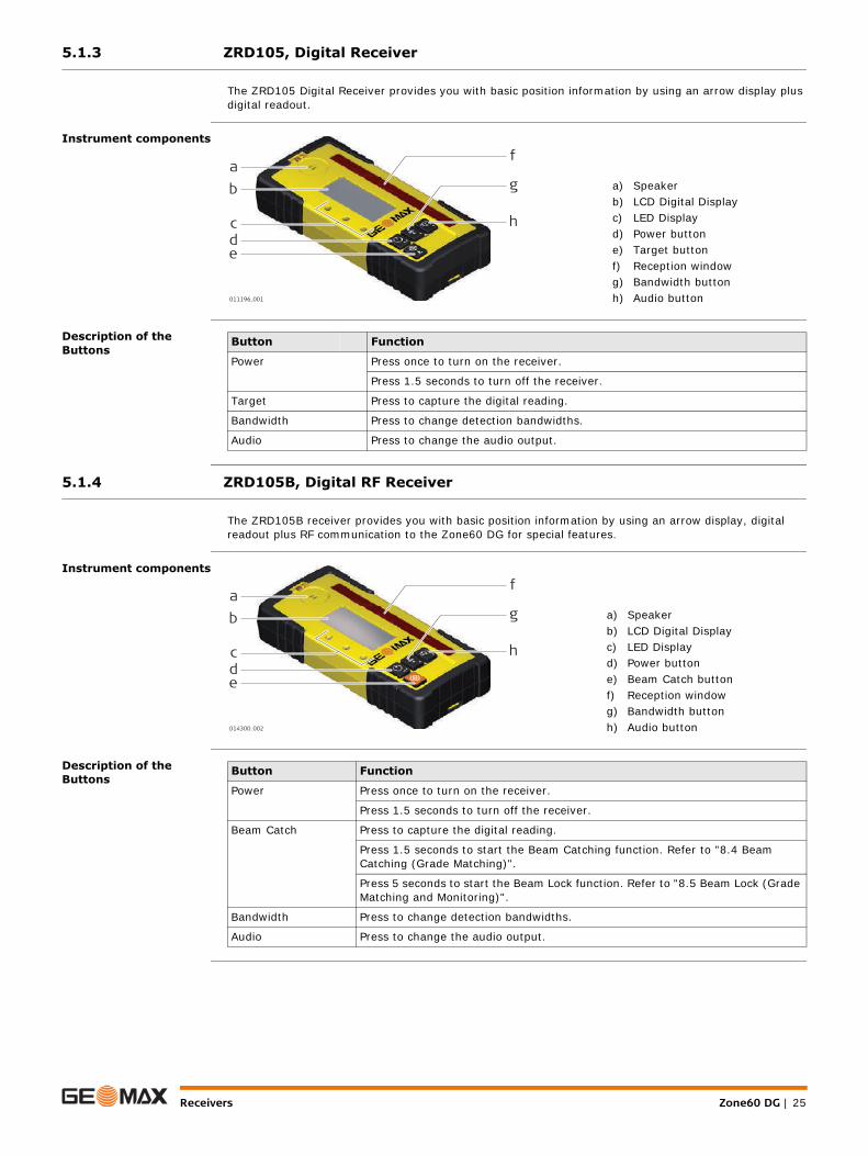
5.1.3 ZRD105, Digital Receiver
The ZRD105 Digital Receiver provides you with basic position information by using an arrow display plus digital readout.
Instrument components
Description of the Buttons
5.1.4 ZRD105B, Digital RF Receiver
The ZRD105B receiver provides you with basic position information by using an arrow display, digital readout plus RF communication to the Zone60 DG for special features.
Instrument components
Description of the Buttons
a) Speakerb) LCD Digital Displayc) LED Displayd) Power buttone) Target buttonf) Reception windowg) Bandwidth buttonh) Audio button011196_001
ab
cde
f
g
h
Button Function
Power Press once to turn on the receiver.
Press 1.5 seconds to turn off the receiver.
Target Press to capture the digital reading.
Bandwidth Press to change detection bandwidths.
Audio Press to change the audio output.
a) Speakerb) LCD Digital Displayc) LED Displayd) Power buttone) Beam Catch buttonf) Reception windowg) Bandwidth buttonh) Audio button014300_002
ab
cde
f
g
h
Button Function
Power Press once to turn on the receiver.
Press 1.5 seconds to turn off the receiver.
Beam Catch Press to capture the digital reading.
Press 1.5 seconds to start the Beam Catching function. Refer to "8.4 Beam Catching (Grade Matching)".
Press 5 seconds to start the Beam Lock function. Refer to "8.5 Beam Lock (Grade Matching and Monitoring)".
Bandwidth Press to change detection bandwidths.
Audio Press to change the audio output.
Zone60 DG | 26Receivers
5.2 Using the ZRD105B Receiver with the Zone60 DG
Special Functions when using ZRD105B Receiver
The Zone60 DG can be used with almost any receiver.However, when used with the ZRD105B receiver, the following special functions are available:• Beam Catching - Allows you to match an existing grade. (Refer to "8.4 Beam Catching (Grade
Matching)")• Beam Lock - Monitors the grade position to keep it on grade. (Refer to "8.5 Beam Lock (Grade Matching
and Monitoring)")Before using the special functions, the Zone60 DG and the ZRD105B must be paired together to be able to communicate with each other. (Refer to "5.3 Pairing the ZRD105B with the Zone60 DG")
5.3 Pairing the ZRD105B with the Zone60 DG
Pairing step-by-step The Zone60 DG and the ZRD105B Receiver include radio devices that allow you to activate the functions on the Zone60 DG remotely up to 100 m (300’) from the Zone60 DG.Before using the RF features, the Zone60 DG and the Receiver must be paired together to be able to communicate with each other.
Step Description
1. Turn off the Zone60 DG.
2. Press and hold the Power Button on the Zone60 DG for 5 seconds to turn on the Zone60 DG in pairing mode. The Zone60 DG beeps five times slowly.
3. Press and hold the Power Button on the Receiver until pairing is confirmed.
When the pairing is successful: Both the Zone60 DG and the Receiver beep five times and the LEDs are flashing (green). There is no confirmation on the LCD displays during this process.
When the pairing is not successful:The Status LED on the Zone60 DG flashes (red) quickly five times.
Zone60 DG Menu Zone60 DG | 27
6 Zone60 DG Menu6.1 Access and Navigation
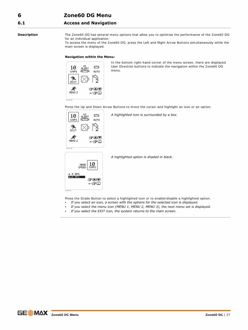
Description The Zone60 DG has several menu options that allow you to optimise the performance of the Zone60 DG for an individual application.To access the menu of the Zone60 DG, press the Left and Right Arrow Buttons simultaneously while the main screen is displayed.
Navigation within the Menu:
In the bottom right-hand corner of the menu screen, there are displayed User Direction buttons to indicate the navigation within the Zone60 DG menu.
Press the Up and Down Arrow Buttons to move the cursor and highlight an icon or an option.
A highlighted icon is surrounded by a box.
A highlighted option is shaded in black.
Press the Grade Button to select a highlighted icon or to enable/disable a highlighted option.• If you select an icon, a screen with the options for the selected icon is displayed.• If you select the menu icon (MENU 1, MENU 2, MENU 3), the next menu set is displayed.• If you select the EXIT icon, the system returns to the main screen.
007606_001
007607_001
007608_001
Zone60 DG | 28Zone60 DG Menu
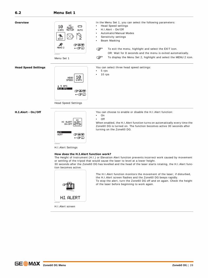
6.2 Menu Set 1
Overview
Head Speed Settings
H.I.Alert - On/Off
Menu Set 1
In the Menu Set 1, you can select the following parameters:• Head Speed settings• H.I.Alert - On/Off• Automatic/Manual Modes• Sensitivity settings• Beam Masking
To exit the menu, highlight and select the EXIT icon.OR: Wait for 8 seconds and the menu is exited automatically.
To display the Menu Set 2, highlight and select the MENU 2 icon.007606_001
Head Speed Settings
You can select three head speed settings:• 5 rps• 10 rps
007608 001
H.I.Alert Settings
You can choose to enable or disable the H.I.Alert function:• On• OffWhen enabled, the H.I.Alert function turns on automatically every time the Zone60 DG is turned on. The function becomes active 30 seconds after turning on the Zone60 DG.
How does the H.I.Alert function work?The Height of Instrument (H.I.) or Elevation Alert function prevents incorrect work caused by movement or settling of the tripod that would cause the laser to level at a lower height.30 seconds after the Zone60 DG has levelled and the head of the laser starts rotating, the H.I.Alert func-tion becomes active.
H.I.Alert screen
The H.I.Alert function monitors the movement of the laser; if disturbed, the H.I.Alert screen flashes and the Zone60 DG beeps rapidly.To stop the alert, turn the Zone60 DG off and on again. Check the height of the laser before beginning to work again.
007609_001
007610_001
Zone60 DG Menu Zone60 DG | 29
Automatic/Manual mode
Automatic/Manual Mode Settings
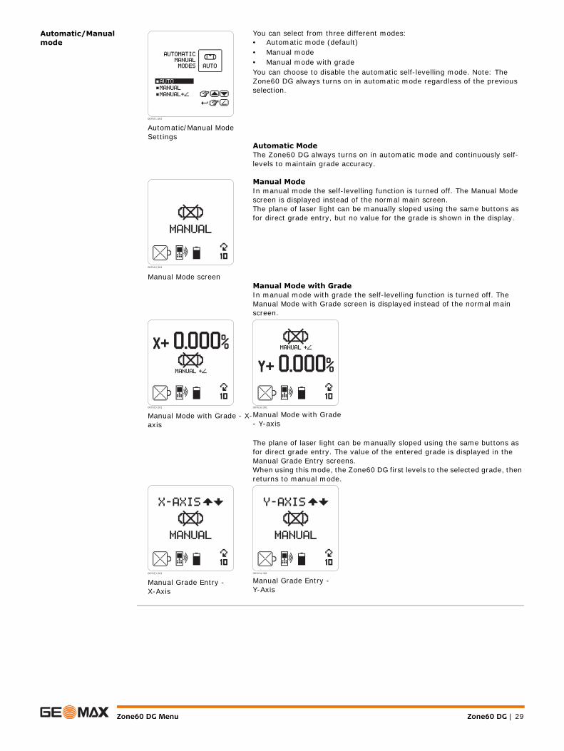
You can select from three different modes:• Automatic mode (default)• Manual mode• Manual mode with gradeYou can choose to disable the automatic self-levelling mode. Note: The Zone60 DG always turns on in automatic mode regardless of the previous selection.
Automatic ModeThe Zone60 DG always turns on in automatic mode and continuously self-levels to maintain grade accuracy.
Manual Mode screen
Manual ModeIn manual mode the self-levelling function is turned off. The Manual Mode screen is displayed instead of the normal main screen.The plane of laser light can be manually sloped using the same buttons as for direct grade entry, but no value for the grade is shown in the display.
Manual Mode with GradeIn manual mode with grade the self-levelling function is turned off. The Manual Mode with Grade screen is displayed instead of the normal main screen.
Manual Mode with Grade - X-axis
Manual Mode with Grade- Y-axis
The plane of laser light can be manually sloped using the same buttons as for direct grade entry. The value of the entered grade is displayed in the Manual Grade Entry screens.When using this mode, the Zone60 DG first levels to the selected grade, then returns to manual mode.
Manual Grade Entry - X-Axis
Manual Grade Entry - Y-Axis
007611_001
007612_001
007615_001 007616_001
007613_001 007614_001

Zone60 DG | 30Zone60 DG Menu
Sensitivity Settings
Beam Masking
Sensitivity Variable Screens
While levelling, the Zone60 DG responds to disturbances (wind, vibrations) and stops the head rotation, if necessary. You can choose between two levels of sensitivity:
• Sensitivity Setting 1: For normal performance - wind, vibration and other disturbances are minimal.
• Sensitivity Setting 2: For situations when wind, vibration and other disturbances are more severe.
When enabled, the H.I.Alert function turns on automatically every time the Zone60 DG is turned on. The function becomes active 30 seconds after turning on the Zone60 DG.
007617_001
007618_001
Beam Masking Screen
Beam masking allows you to turn off the laser beam on selected sides of the laser to prevent interference with other lasers or receivers that could be working in the same working area.
Possible combinations
You can choose to block half or three quarters of the rotating laser beam.Each of the four displayed combinations is available in four different vari-ants. The dark area represents the area where the laser beam is turned off.Use the Up or Down Arrow Buttons to choose from the 16 possible combi-nations.
007619_001
007620_001
011231_001

Zone60 DG Menu Zone60 DG | 31
6.3 Menu Set 2
Overview
Display Brightness
Save Beam Masking at Power Off
Menu Set 2
In the Menu Set 2, you can select the following parameters:• Display Brightness• Beam masking - Save at power off• Temperature Sensitivity• Negative Grade - enable/disable• Radio - enable/disable
To exit the menu, highlight and select the EXIT icon.OR: Wait for 8 seconds and the menu is exited automatically.
To display the Menu Set 3, highlight and select the MENU 3 icon.007621_001
Display Brightness screen
With this setting, you can change the display brightness.Use the Up and Down Arrow Buttons to adjust the brightness as desired.
007622_001
Save Beam Masking screens
Normally, the beam masking setting is disabled every time you turn off the Zone60 DG.If you prefer to save the beam masking settings for usage on the following day, you can enable the saving of the beam masking setting:• Save: The beam masking settings are saved at power off.• Don’t save: The beam masking settings are disabled at power off.
007623_001
007624_001
Zone60 DG | 32Zone60 DG Menu
Temperature Sensi-tivity Settings
Negative Grade - Enable/Disable
Temperature Check Settings screens
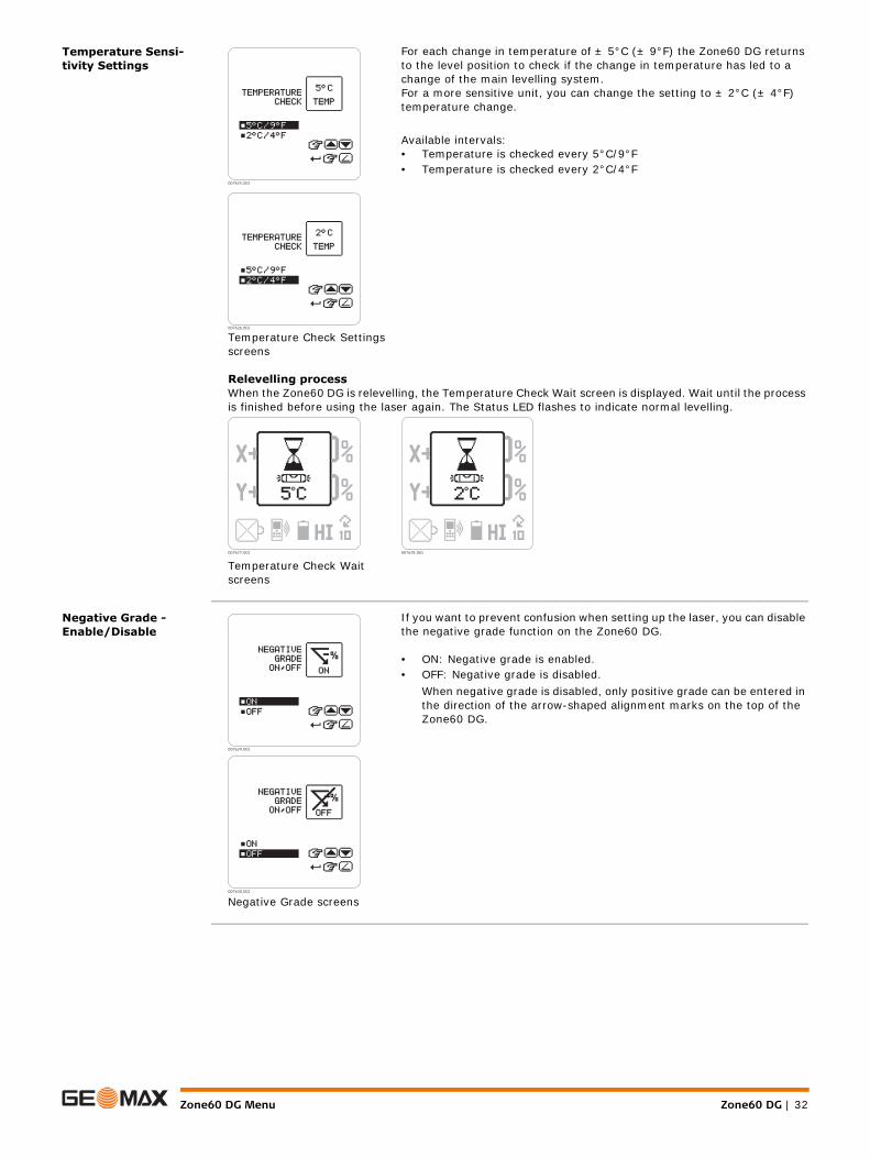
For each change in temperature of ± 5°C (± 9°F) the Zone60 DG returns to the level position to check if the change in temperature has led to a change of the main levelling system.For a more sensitive unit, you can change the setting to ± 2°C (± 4°F) temperature change.
Available intervals:• Temperature is checked every 5°C/9°F• Temperature is checked every 2°C/4°F
Relevelling processWhen the Zone60 DG is relevelling, the Temperature Check Wait screen is displayed. Wait until the process is finished before using the laser again. The Status LED flashes to indicate normal levelling.
Temperature Check Wait screens
007625_001
007626_001
007627_001 007628_001
Negative Grade screens
If you want to prevent confusion when setting up the laser, you can disable the negative grade function on the Zone60 DG.
• ON: Negative grade is enabled.• OFF: Negative grade is disabled.
When negative grade is disabled, only positive grade can be entered in the direction of the arrow-shaped alignment marks on the top of the Zone60 DG.
007629_001
007630_001

Zone60 DG Menu Zone60 DG | 33
Radio - Enable/Disable
6.4 Menu Set 3
Overview
Customer Name Settings
The Customer Name settings allow you to enter the customer’s name, to enable/disable the customer name screen when turning on the Zone60 DG, and to protect the name entry with a password.Customer Name Entry
It is recommended to determine the desired text before changing or entering the information:
To save the entered information, press and hold the Grade Button for 1.5 seconds.
Enable/Disable the Display Name on Start-upAfter saving the name entry, the Display Name on Start-up screen is displayed. You can choose between two options:
Radio screens
To be able to communicate with the ZRC60 remote control and the receiver, the radio on the Zone60 DG must be enabled. The radio is auto-matically enabled when the units are paired together.
• ON: Radio is enabled.• OFF: Radio is disabled.
If you do not use the remote control or the receiver, it is recom-mend to disable radio in order to save battery life.
007631_001
007632_001
Menu Set 3
In the Menu Set 3, you can select the following parameters:• Customer Name Entry• Display - Percent/Per Mil• Display - Thousandths/Hundredths• Show Grade Settings on power up• Calibration Alert - enable/disable
To exit the menu, highlight and select the EXIT icon.OR: Wait for 8 seconds and the menu is exited automatically.
To display the Menu Set 1, highlight and select the MENU 1 icon.007633_001
Customer Name Entry screen
When entering the Customer Name settings the first time, you are taken directly to the Customer Name entry screen. On this screen, you can enter 6 lines of text with up to 20 characters per line.
007634_001

Zone60 DG | 34Zone60 DG Menu
• Display (YES): The Customer Name screen is displayed each time the laser is turned on.• Save only (NO): The information entered in the Customer Name screen is stored in the laser, but is
only visible when the Customer Name entry screen is accessed.
Protect Customer Name Entry with a PasswordAfter selecting the Display on Start-up setting, you can choose to enable/disable the password protection of the Customer Name entry screen:
• YES: Password protection is enabled. Enter a four-digit password. The password is required each time you access the customer name entry screen.
• NO: Password protection is disabled.
Display - Percent/Per Mil
Display Name on Start-Up screens
New Password screens
007635_001 007636_001
007637_001 007638_001
You can choose to display the grade in percent of grade or per mil:• 1.000% = 1 metre rise per 100 metres• 1.00‰ = 1 metre rise per 1000 metres
Display Percent Display per Mil
Standard usage is percent of grade.You are asked to confirm the selected option to prevent unwanted changes and possible errors due to the shift of the decimal point.
Per Mil - Confirmation Screens
007639_001 007640_001
007641_001 007642_001

Zone60 DG Menu Zone60 DG | 35
Display - Thousandths or Hundredths
Show Grade Settings on Power Up
Note: When the option Show 0.000% is selected and you want to restore the last set grade(s), press and hold the Grade Button for 1.5 seconds.
Calibration alert activa-tion
Enabling/Disabling the Calibration Alert Function
Setting the Hours for Calibration Alert
You can choose to display percent of grade in thousandths or hundredths:• 1.000 - Standard usage is to display thousandths or three digits after the decimal point.• 1.00 - If you choose to display hundredths, only two digits are displayed after the decimal point.
Display Thousandths Display Hundredths007643_001 007644_001
Normally, the grade value is reset to 0.000% every time you turn on the Zone60 DG.If you prefer to display the previous grade settings when turning on the Zone60 DG, you can enable the option Show Grade.
• Show 0.000: The grade settings are reset to 0.000% on power up (default).• Show Grade: The previous grade settings are displayed on power up.
Show 0.000% Show Grade008xxx_001 008xxx_001
You can choose to enable/disable a calibration alert function based on hours of use:• ON: Calibration alert is enabled• OFF: Calibration alert is disabled
Enable Calibration Alert Screen
Disable Calibration Alert Screen
If you enabled the calibration alert function, the “Set Calibration Alert Hours” screen is displayed. The default setting is 1.040 hours, which corresponds to approximately 6 months, based on a 40-hour working week.
007645_001 007646_001
Zone60 DG | 36Zone60 DG Menu
Display of Calibration Alert on Start-up Screen
Set Calibration Alert Hours Screen
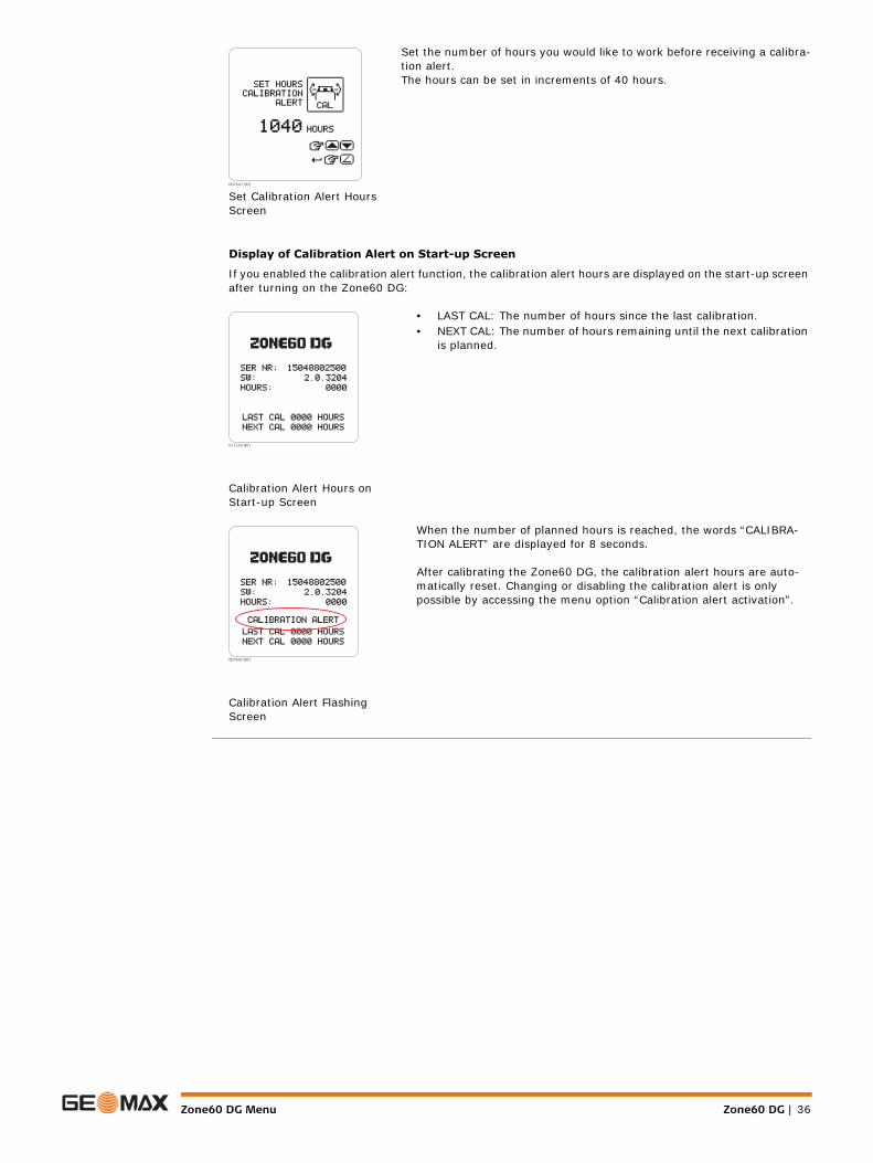
Set the number of hours you would like to work before receiving a calibra-tion alert.The hours can be set in increments of 40 hours.
If you enabled the calibration alert function, the calibration alert hours are displayed on the start-up screen after turning on the Zone60 DG:
Calibration Alert Hours on Start-up Screen
• LAST CAL: The number of hours since the last calibration.• NEXT CAL: The number of hours remaining until the next calibration
is planned.
Calibration Alert Flashing Screen
When the number of planned hours is reached, the words “CALIBRA-TION ALERT” are displayed for 8 seconds.
After calibrating the Zone60 DG, the calibration alert hours are auto-matically reset. Changing or disabling the calibration alert is only possible by accessing the menu option “Calibration alert activation”.
007647_001
011339_001
007649_001

ZRC60 Menu Zone60 DG | 37
7 ZRC60 Menu
Overview
Display Brightness
Sleep Mode Hours
Remote Shut-Off Time
Remote Control Menu Screen
The ZRC60 Remote Control has its own menu where you can change the following parameters:• Display Brightness• Sleep Mode Hours• Remote Shut-Off Time
To access the Remote Control menu, press and hold the Left and Right Arrow Buttons on the remote control for 1.5 seconds.
For navigation within the Remote Control menu, use the same buttons as for navigation within the Zone60 DG menu. (Refer to "6.1 Access and Navigation")
007650_001
Remote Control Display Brightness
You can change the display brightness on this screen.Use the Up and Down Arrow Buttons to adjust the brightness as desired.
007651_001
Sleep Mode Hours
You can determine how long the Zone60 DG stays in sleep mode before turning off completely:• 2 hours• 4 hours• 8 hours• 16 hours
007652_001
Shut-Off Time
You can determine a shut-off time for the remote control:• 30 seconds• 60 seconds• 120 secondsIf the remote control is not used during this time, it shuts off automatically.
007653_001

Zone60 DG | 38Applications
8 Applications8.1 Setting Forms
Setting Forms step-by-step
Application shown using the ZRP105 Receiver.
Step Description
1. Set up the Zone60 DG on a tripod.
2. Set up the tripod on a stable surface outside the working area.
3. Attach the receiver to a rod.
4. Turn on the Zone60 DG and the receiver.
5. Set the base of the rod on a known point for the finished height of forms.
6. Adjust the height of the receiver on the rod until the on-grade (centre-line) position is indicated on the receiver by:• the centre bar• the green flashing LED• a solid audio tone
7. Set the rod with the attached receiver on top of the form.
8. Adjust the height of the form until the on-grade position is again indicated.
9. Continue to additional positions until the forms are levelled to the rotating plane of the Zone60 DG.
ba
4
011223_001
65
7
8
9
1 + 2
3
Applications Zone60 DG | 39
8.2 Checking Grades
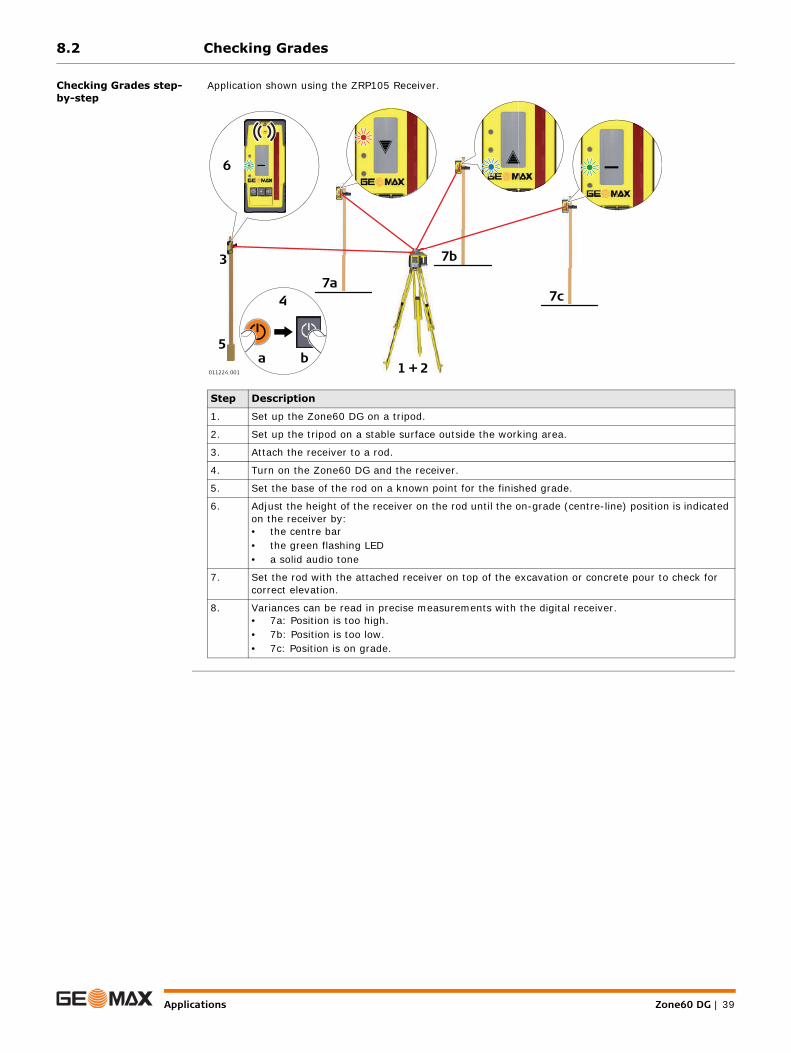
Checking Grades step-by-step
Application shown using the ZRP105 Receiver.
Step Description
1. Set up the Zone60 DG on a tripod.
2. Set up the tripod on a stable surface outside the working area.
3. Attach the receiver to a rod.
4. Turn on the Zone60 DG and the receiver.
5. Set the base of the rod on a known point for the finished grade.
6. Adjust the height of the receiver on the rod until the on-grade (centre-line) position is indicated on the receiver by:• the centre bar• the green flashing LED• a solid audio tone
7. Set the rod with the attached receiver on top of the excavation or concrete pour to check for correct elevation.
8. Variances can be read in precise measurements with the digital receiver.• 7a: Position is too high.• 7b: Position is too low. • 7c: Position is on grade.
6
ba
4
011224_001
3
1 + 2
5
7a
7b
7c
Zone60 DG | 40Applications
8.3 Entering Grades
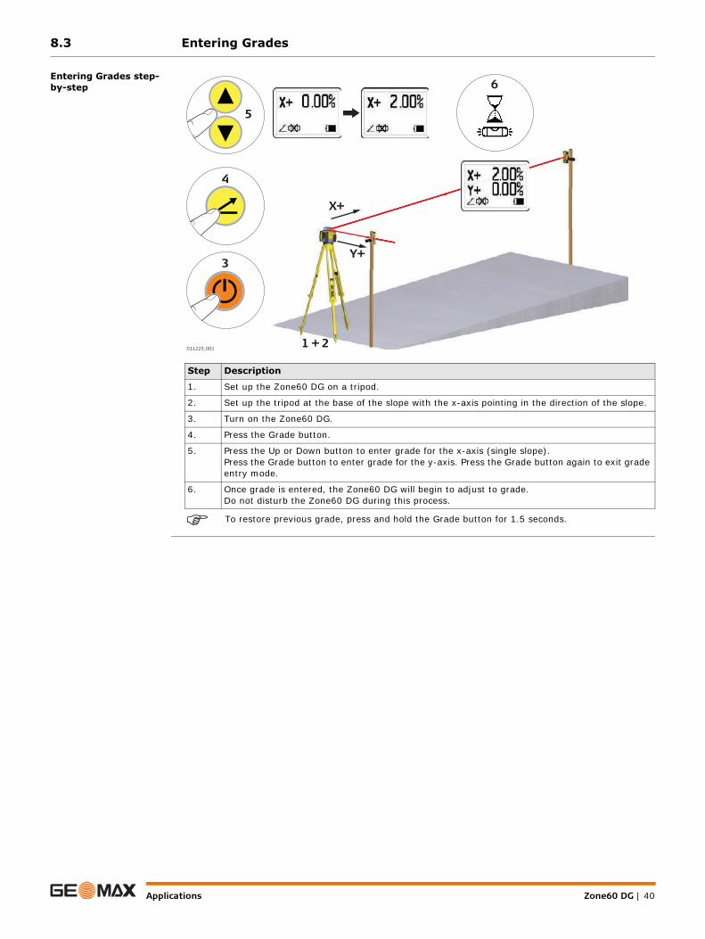
Entering Grades step-by-step
To restore previous grade, press and hold the Grade button for 1.5 seconds.
Step Description
1. Set up the Zone60 DG on a tripod.
2. Set up the tripod at the base of the slope with the x-axis pointing in the direction of the slope.
3. Turn on the Zone60 DG.
4. Press the Grade button.
5. Press the Up or Down button to enter grade for the x-axis (single slope).Press the Grade button to enter grade for the y-axis. Press the Grade button again to exit grade entry mode.
6. Once grade is entered, the Zone60 DG will begin to adjust to grade. Do not disturb the Zone60 DG during this process.
4
5
3
6
011225_001 1 + 2
X+
Y+

Applications Zone60 DG | 41
8.4 Beam Catching (Grade Matching)
Beam Catching step-by-step using the ZRD105B
Using the Beam Catching feature you can match an existing grade. The Zone60 DG moves to the new grade position, displays the grade found and begins self-levelling to maintain the grade over time. Maximum range is 100 m (300’).
Step Description
The Beam Catching process can only be run on the X-axis in horizontal mode.
1. Set up the Zone60 DG at the base of a slope with no grade dialled into the Zone60 DG and with the X-axis pointing in the direction of the slope.
2. Adjust the height of the receiver on the rod at the base of the slope until the on-grade (centre-line) position is indicated on the receiver by:• the centre bar• the green flashing LED• a solid audio tone• the digital display
3. Move the rod with the receiver to the top of the slope. To start the Beam Catching process, press the Beam Catch button for 1.5 seconds.• The Zone60 DG searches for the receiver until the on-grade position is found. The receiver
shows SMT, then XSC while catching the beam on the X-axis. • Once the on-grade position is found, the receiver flashes all three LEDs simultaneously one
time and the receiver returns to normal operation.
4. After this signal, the receiver can be moved and used as normal. The grade for the sloped axis is displayed on the LCD display and the Zone60 DG now self-levels to this new slope.
α
014301_002
12
X
α
4XSC
SMT1.5 s
3

Zone60 DG | 42Applications
8.5 Beam Lock (Grade Matching and Monitoring)
Beam Lock step-by-step using the ZRD105B
Using the Beam Lock feature, you can match an existing grade and monitor the laser beam. The Zone60 DG moves to the new grade position, displays the grade found and begins self-levelling to maintain the grade over time. The ZRD105B must remain in place to monitor any movements of the rotating beam. Thus, an accurate grade setup is maintained. Maximum range is 100 m (300’).
Step Description
The Beam Lock process can only be run on the X-axis in horizontal mode.
1. Ensure that the grade value is set to zero.Set up the Zone60 DG at the base of a slope with the X-axis pointing in the direction of the slope.
2. At the base of the slope, adjust the height of the ZRD105B receiver on the rod until the on-grade (centreline) position is indicated on the receiver by:• the centre bar• the green flashing LED• a solid audio tone• the digital display
3. Move the rod with the receiver to the top of the slope. To start the Beam Lock process, press the Beam Catch button for 5 seconds.• The Zone60 DG searches for the receiver until the on-grade position is found. The receiver
shows SML, then XSL while catching and locking the beam on the X-axis.• Once the on-grade position is found, the receiver flashes all three LEDs simultaneously one
time.• The display shows LOC while the receiver is in lock mode.
4. After this signal, the receiver must remain in place to monitor any movements of the rotating beam. The grade for the sloped axis is displayed on the LCD display of the Zone60 DG.
To turn off the Beam Lock mode on the receiver, hold the Power Button for 1.5 seconds.
To lock and monitor the rotating beam of an existing grade, mount the receiver in the plane of the laser before starting the Beam Lock process.
5 s
3 α4 XSL
LOC
SML
2
014302_002 1
X
α

Batteries Zone60 DG | 43
9 Batteries
Description The Zone60 DG can be purchased with alkaline batteries or a rechargeable Li-Ion battery pack.The following information is appropriate only to the model you have purchased.
9.1 Operating Principles
First-time Use / Charging Batteries
• The battery must be charged prior to using it for the first time because it is delivered with an energy content as low as possible.
• The permissible temperature range for charging is between 0°C to +40°C/ +32°F to +104°F. For optimal charging, we recommend charging the batteries at a low ambient temperature of +10°C to +20°C/+50°F to +68°F if possible.
• It is normal for the battery to become warm during charging. Using the chargers recommended by GeoMax, it is not possible to charge the battery if the temperature is too high.
• For new batteries or batteries that have been stored for a long time (> three months), it is effectual to make only one charge/discharge cycle.
• For Li-Ion batteries, a single discharging and charging cycle is sufficient. We recommend carrying out the process when the battery capacity indicated on the charger or on a GeoMax product deviates signif-icantly from the actual battery capacity available.
Operation / Discharging • The batteries can be operated from −20 °C to +55 °C/−4 °F to +131 °F.• Low operating temperatures reduce the capacity that can be drawn; high operating temperatures
reduce the service life of the battery.
9.2 Battery for Zone60 DG
Charging the Li-Ion battery pack step-by-step
The rechargeable Li-Ion battery pack on the Zone60 DG can be charged without removing the battery pack from the laser.
The battery pack reaches a full charge in approximately 5 hours if completely empty. A one-hour charge should allow the Zone60 DG to run for a full 8 hours.
Step Description
1. Slide the locking mechanism on the battery compartment to the centre position to expose the charge jack.
2. Plug the AC connector into the appropriate AC power source.
3. Connect the charger plug into the charge jack on the Zone60 DG battery pack.
4. The small LED next to the charge jack flashes indicating that the Zone60 DG is charging. The LED is on solid when the battery pack is fully charged.
5. When the battery pack is fully charged, disconnect the charger plug from the charge jack.
6. Slide the locking mechanism to the left position to prevent dirt from getting into the charging jack.
4
011226_001
1 3
2
5
6
Zone60 DG | 44Batteries
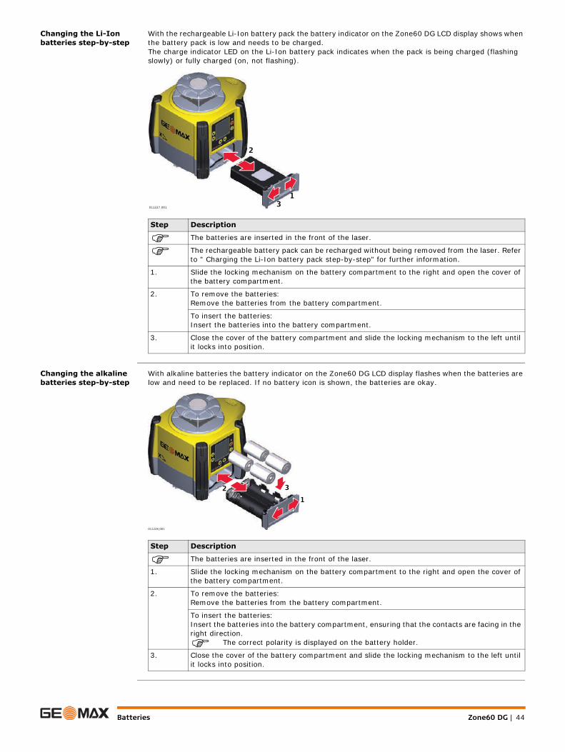
Changing the Li-Ion batteries step-by-step
With the rechargeable Li-Ion battery pack the battery indicator on the Zone60 DG LCD display shows when the battery pack is low and needs to be charged.The charge indicator LED on the Li-Ion battery pack indicates when the pack is being charged (flashing slowly) or fully charged (on, not flashing).
Changing the alkaline batteries step-by-step
With alkaline batteries the battery indicator on the Zone60 DG LCD display flashes when the batteries are low and need to be replaced. If no battery icon is shown, the batteries are okay.
Step Description
The batteries are inserted in the front of the laser.
The rechargeable battery pack can be recharged without being removed from the laser. Refer to " Charging the Li-Ion battery pack step-by-step" for further information.
1. Slide the locking mechanism on the battery compartment to the right and open the cover of the battery compartment.
2. To remove the batteries:Remove the batteries from the battery compartment.
To insert the batteries:Insert the batteries into the battery compartment.
3. Close the cover of the battery compartment and slide the locking mechanism to the left until it locks into position.
011227_001
1
2
3
Step Description
The batteries are inserted in the front of the laser.
1. Slide the locking mechanism on the battery compartment to the right and open the cover of the battery compartment.
2. To remove the batteries:Remove the batteries from the battery compartment.
To insert the batteries:Insert the batteries into the battery compartment, ensuring that the contacts are facing in the right direction.
The correct polarity is displayed on the battery holder.
3. Close the cover of the battery compartment and slide the locking mechanism to the left until it locks into position.
011228_001
12
3
3

Accuracy Adjustment Zone60 DG | 45
10 Accuracy Adjustment
About • It is the responsibility of the user to follow operating instructions and to periodically check the accuracy of the laser and work as it progresses.
• The Zone60 DG is adjusted to the defined accuracy specification at the factory. It is recommended to check the laser for accuracy upon receipt and periodically thereafter to ensure accuracy is maintained. If the laser requires adjustment, contact your nearest authorised service centre or adjust the laser using the procedures described in this chapter.
• Only enter the accuracy adjustment mode when you plan to change the accuracy. Accuracy adjust-ments should only be performed by a qualified individual that understands basic adjustment principles.
• It is recommended to perform this procedure with two people on a relatively flat surface.
10.1 Checking the Level Accuracy
Checking the level accu-racy step-by-step
The Zone60 DG is within its accuracy specification if the four marks are within ± 1.5 mm (± 1/16") from the centre.
Step Description
1. Place the Zone60 DG on a flat, level surface or tripod approximately 30 m (100 ft) from a wall.
2. Align the first axis so that it is square to a wall. Allow the Zone60 DG to self-level completely (approximately 1 minute after the Zone60 DG begins to rotate).
3. Mark the position of the beam.
4. Rotate the laser 180° and allow it to self-level.
5. Mark the opposite side of the first axis.
6. Align the second axis of the Zone60 DG by rotating it 90° so that this axis is square to the wall. Allow the Zone60 DG to self-level completely.
7. Mark the position of the beam.
8. Rotate the laser 180° and allow it to self-level.
9. Mark the opposite side of the second axis.
011292_001
30 m (100 ft)
30 m (100 ft)
X+
X—
011293_001
30 m (100 ft)
30 m (100 ft)
Y+
Y—

Zone60 DG | 46Accuracy Adjustment
10.2 Adjusting the Level Accuracy
Description
Entering Calibration mode step-by-step
In Calibration mode, the LED does not blink and the laser head continues to rotate. An hour-glass indicates that the Zone60 DG is levelling.
Calibrating the X-axis step-by-step
When entering Calibration mode, the X-axis calibration screen appears:
In Adjustment Mode the X-axis LED indicates changes to the X-axis.
The Y-axis LED indicates changes to the Y-axis
011294_001
X
011295_001
Y
Step Description
1. Turn off the power.
2. Put the Zone60 DG in an upright position.
3. Press and hold both the Up and Down Arrow buttons.
4. Press the Power button. The X-axis calibration screen appears. The Zone60 DG is now in Cali-bration mode.
Step Description
1. When the hour glass has disappeared, indicating that the Zone60 DG has levelled, check both sides of the X-axis.
2. Press the Up and Down Arrow Buttons to bring the plane of laser light to the specified level position.
Each step represents approximately 2 arc seconds of change. Therefore, 5 steps equal approximately 1.5 mm at 30 m (1/16" at 100’).
3. Press the Grade Button to accept the adjusted position and to switch to the Y-axis calibration screen.
007733_001
Accuracy Adjustment Zone60 DG | 47
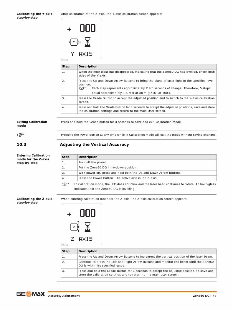
Calibrating the Y-axis step-by-step
After calibration of the X-axis, the Y-axis calibration screen appears:
Exiting Calibration mode
Press and hold the Grade button for 3 seconds to save and exit Calibration mode.
Pressing the Power button at any time while in Calibration mode will exit the mode without saving changes.
10.3 Adjusting the Vertical Accuracy
Entering Calibration mode for the Z-axis step-by-step
In Calibration mode, the LED does not blink and the laser head continues to rotate. An hour-glass indicates that the Zone60 DG is levelling.
Calibrating the Z-axis step-by-step
When entering calibration mode for the Z-axis, the Z-axis calibration screen appears:
Step Description
1. When the hour glass has disappeared, indicating that the Zone60 DG has levelled, check both sides of the Y-axis.
2. Press the Up and Down Arrow Buttons to bring the plane of laser light to the specified level position.
Each step represents approximately 2 arc seconds of change. Therefore, 5 steps equal approximately 1.5 mm at 30 m (1/16" at 100’).
3. Press the Grade Button to accept the adjusted position and to switch to the X-axis calibration screen.
4. Press and hold the Grade Button for 3 seconds to accept the adjusted positions, save and store the calibration settings and return to the Main User screen.
007734_001
Step Description
1. Turn off the power.
2. Put the Zone60 DG in laydown position.
3. With power off, press and hold both the Up and Down Arrow Buttons.
4. Press the Power Button. The active axis is the Z-axis.
Step Description
1. Press the Up and Down Arrow Buttons to increment the vertical position of the laser beam.
2. Continue to press the Left and Right Arrow Buttons and monitor the beam until the Zone60 DG is within its specified range.
3. Press and hold the Grade Button for 3 seconds to accept the adjusted position, to save and store the calibration settings and to return to the main user screen.
007735_001

Zone60 DG | 48Troubleshooting
11 Troubleshooting
Alerts and Message Screens
Alert Symptom Possible causes and solutions
Low Battery indication on the display.
The batteries are low. Replace the alkaline batteries or recharge the Li-Ion battery pack. Refer to "9 Batteries".
Elevation (H.I.) AlertThe Elevation (H.I.) Alert screen is shown and the audio beeps.(Level position)
The Zone60 DG has been bumped or tripod was moved. Turn off Zone60 DG to stop alert, check the height of the laser before beginning to work again. Allow Zone60 DG to relevel and check the height of the laser.After 2 minutes in the alert condition, the unit will shut off automatically.
Servo Limit AlertThe Servo Limit Alert screen is shown.
The Zone60 DG is tipped too far to reach a level position. Relevel the Zone60 DG within the 6 degree self-levelling range.After 2 minutes in the alert condition, the unit will shut off automatically.
Tilt AlertThe Tilt Alert screen is shown.
The Zone60 DG is tipped more than 45° from level.After 2 minutes in the alert condition, the unit will shut off automatically.
Temperature AlertThe Temperature Alert screen is shown.
The Zone60 DG is in an environment where it cannot operate without damaging the laser diode, for example being exposed to the heat from direct sunlight. Shade the Zone60 DG from the sun.After 2 minutes in the alert condition, the unit will shut off automatically.
Temperature CheckThe Temperature Check Alert screen is shown.
The Zone60 DG has detected a change in temperature of 5°C and is checking the level position.
Wait until procedure is complete. Refer to " Temperature Sensitivity Settings" for changing the setting between 5°C and 2°C.
Negative grade entry is not possible.
The negative grade function is disabled. Only positive grade can be entered in the Zone60 DG. To enter negative grade, enable the negative grade function. Refer to " Negative Grade - Enable/Disable".
The “empty battery” icon flashes.
The Zone60 DG has reached a low battery condi-tion and changes the head speed to 7rps. If the receiver detects the Zone60 DG rotating at 7 rps, it displays a small flashing Zone60 DG.
Check the battery of the Zone60 DG.
007746_001
007610_001
007747_001
007748_001
007749_001
007627_001
007750_001
007751_001

Troubleshooting Zone60 DG | 49
Troubleshooting
The beam is not emitting from all sides of the laser.
Beam masking is activated for two or more sides of the laser. To de-activate or change beam masking, refer to " Beam Masking".
It is not possible to enter grade greater than 10.00% or 3.000%.
The Zone60 DG allows for up to 10% grade entry in both axes simultaneously. If the grade entry for one axis is greater than 10%, the cross axis is limited to 3%.
The Zone60 DG is not communicating with the remote control.
The Zone60 DG has lost the communication link to the remote control.
Ensure that you are within clear sight of the Zone60 DG and that you have not exceeded the 100 m (300’) working range.
Alert Symptom Possible causes and solutions
007752_001
007753_001
007600_001
Problem Possible Causes Suggested Solutions
The Zone60 DG does not turn on.
The batteries are low or dead. Check the batteries and change or charge the batteries if necessary. If the problem continues, return the Zone60 DG to an authorised service centre for service.
The distance of the laser is reduced.
Dirt is reducing the laser output.
Clean the windows of the Zone60 DG and the receiver. If the problem continues, return the Zone60 DG to an authorised service centre for service.
The laser receiver is not working properly.
The Zone60 DG is not rotating. It may be levelling or in H.I.Alert.
Check for proper operation of the Zone60 DG.
Refer to the receiver manual for more information.
The receiver is out of usable range.
Move closer to the Zone60 DG.
The batteries of the receiver are low.
Check the low battery symbol on the receiver display. Change the receiver batteries.
The ZRC60 remote control is not working properly.
The remote control is out of usable range.
For normal operation, the remote control works up to 300 m (1,000’).
The batteries of the remote are low.
Check the Remote Battery LED on the control panel. Change the remote control batteries.
The display is too dark or too light.
The setting of the display brightness is unsuitable.
The brightness for both the Zone60 DG and the remote control can be reset in the menu of the respective device. Refer to " Display Bright-ness"(Zone60 DG) or to " Display Bright-ness"(Remote control).
The grade is shown in percent(%) or per mil (‰).
The wrong setting has been selected.
Choose the desired setting in the option menu. (" Display - Percent/Per Mil")
The grade resets to zero each time the laser is turned on.
The wrong setting has been selected.
Choose the desired setting in the option menu. (" Show Grade Settings on Power Up")

Zone60 DG | 50Troubleshooting
The laser stops too often to relevel.
The sensitivity setting may be set to the “fine” setting (Setting 1).
Choose the Sensitivity Setting 2 in the option menu. (" Sensitivity Settings")
The Tripod may be unstable. Check your tripod for stability. Tighten all screws. Use sand bags on the legs if necessary.
The wind is causing the Zone60 DG to move too much.
Shelter the Zone60 DG from the wind. Press the tripod legs more firmly into the ground.
Problem Possible Causes Suggested Solutions
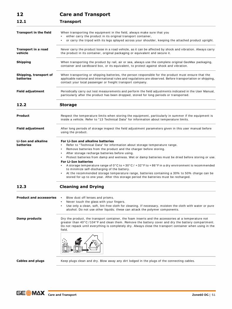
Care and Transport Zone60 DG | 51
12 Care and Transport12.1 Transport
Transport in the field When transporting the equipment in the field, always make sure that you• either carry the product in its original transport container,• or carry the tripod with its legs splayed across your shoulder, keeping the attached product upright.
Transport in a road vehicle
Never carry the product loose in a road vehicle, as it can be affected by shock and vibration. Always carry the product in its container, original packaging or equivalent and secure it.
Shipping When transporting the product by rail, air or sea, always use the complete original GeoMax packaging, container and cardboard box, or its equivalent, to protect against shock and vibration.
Shipping, transport of batteries
When transporting or shipping batteries, the person responsible for the product must ensure that the applicable national and international rules and regulations are observed. Before transportation or shipping, contact your local passenger or freight transport company.
Field adjustment Periodically carry out test measurements and perform the field adjustments indicated in the User Manual, particularly after the product has been dropped, stored for long periods or transported.
12.2 Storage
Product Respect the temperature limits when storing the equipment, particularly in summer if the equipment is inside a vehicle. Refer to "13 Technical Data" for information about temperature limits.
Field adjustment After long periods of storage inspect the field adjustment parameters given in this user manual before using the product.
Li-Ion and alkaline batteries
For Li-Ion and alkaline batteries• Refer to "Technical Data" for information about storage temperature range.• Remove batteries from the product and the charger before storing.• After storage recharge batteries before using.• Protect batteries from damp and wetness. Wet or damp batteries must be dried before storing or use.For Li-Ion batteries• A storage temperature range of 0°C to +30°C / +32°F to +86°F in a dry environment is recommended
to minimize self-discharging of the battery.• At the recommended storage temperature range, batteries containing a 30% to 50% charge can be
stored for up to one year. After this storage period the batteries must be recharged.
12.3 Cleaning and Drying
Product and accessories • Blow dust off lenses and prisms.• Never touch the glass with your fingers.• Use only a clean, soft, lint-free cloth for cleaning. If necessary, moisten the cloth with water or pure
alcohol. Do not use other liquids; these can attack the polymer components.
Damp products Dry the product, the transport container, the foam inserts and the accessories at a temperature not greater than 40°C /104°F and clean them. Remove the battery cover and dry the battery compartment. Do not repack until everything is completely dry. Always close the transport container when using in the field.
Cables and plugs Keep plugs clean and dry. Blow away any dirt lodged in the plugs of the connecting cables.

Zone60 DG | 52Technical Data
13 Technical Data13.1 Conformity to National Regulations
Conformity to national regulations
Frequency band 2400 - 2483.5 MHz
Output power < 100 mW (e. i. r. p.)
Antenna
13.2 Dangerous Goods Regulations
Dangerous Goods Regu-lations
The products of GeoMax are powered by Lithium batteries.
Lithium batteries can be dangerous under certain conditions and can pose a safety hazard. In certain conditions, Lithium batteries can overheat and ignite.
When carrying or shipping your GeoMax product with Lithium batteries onboard a commercial aircraft, you must do so in accordance with the IATA Dangerous Goods Regulations.
GeoMax has developed Guidelines on “How to carry GeoMax products” and “How to ship GeoMax products” with Lithium batteries. Before any transportation of a GeoMax product, we ask you to consult these guidelines on our web page (http://www.geomax-positioning.com/dgr) to ensure that you are in accordance with the IATA Dangerous Goods Regulations and that the GeoMax products can be transported correctly.
Damaged or defective batteries are prohibited from being carried or transported onboard any aircraft. Therefore, ensure that the condition of any battery is safe for transportation.
13.3 General Technical Data of the Laser
Operating range Operating range (diameter):
Self-levelling accuracy
Self-levelling accuracy is defined at 25°C (77°F)
Self-levelling range
Head speed
• FCC Part 15 (applicable in US).• Hereby, GeoMax AG, declares that the product Zone60 DG is in compliance with the essential require-
ments and other relevant provisions of Directive 1999/5/EC and other applicable European Directives. The declaration of conformity may be consulted at http://www.geomax-positioning.com/Down-loads.htm.
Class 1 equipment according European Directive 1999/5/EC (R&TTE) can be placed on the market and be put into service without restrictions in any EU Member state.
• The conformity for countries with other national regulations not covered by the FCC part 15 or Euro-pean directive 1999/5/EC has to be approved prior to use and operation.
• Japanese Radio Law and Japanese Telecommunications Business Law Compliance.– This device is granted pursuant to the Japanese Radio Law and the Japanese Telecommunications
Business Law.– This device should not be modified (otherwise the granted designation number will become
invalid).
Zone60 DG: Chip antennaZRC60 remote control: Chip antenna
Zone60 DG: 1100 m/3600 ft
Self-levelling accuracy: ±1.5 mm at 30 m (±1/16" at 100 ft)
Self-levelling range: ±6°
Head speed: 5, 10 rps

Technical Data Zone60 DG | 53
Laser dimensions
Grade Capability ± 10% in both axes simultaneously, 15% in one axis with up to 3% in the cross axis
Weight
Internal battery
*Operating times are dependent upon environmental conditions.
Charging the Li-Ion battery pack takes a maximum of five hours.
Use only high quality alkaline batteries to achieve operating time.
Environmental specifi-cations
Temperature
Protection against water, dust and sand
Lithium-Ion charger
Lithium-Ion battery pack
011229_001
218
mm
(8.
6")
241 mm (9.5 ") 202 mm (8.0")
Zone60 DG weight with battery: 3.4 kg/7.4 lbs.
Type Operating times* at 20°C
Lithium-Ion (Li-Ion Pack) 40 h
Alkaline (four D-cells) 60 h
Operating temperature Storage temperature
-20°C to +50°C (-4°F to +122°F)
-40°C to +70°C(-40°F to +158°F)
Protection
IP67
Dust tight
Waterproof to 1 m temporary immersion.
Type: Li-Ion battery chargerInput voltage: 100 V AC-240 V AC, 50 Hz-60 HzOutput voltage: 12 V DCOutput current: 3.0 APolarity: Shaft: negative, Tip: positive
Type: Li-Ion battery packInput voltage: 12 V DCInput current: 2.5 ACharge time: 5 hours (maximum) at 20°C

Zone60 DG | 54Technical Data
13.3.1 ZRC60 Remote Control
Operating range
Batteries
Remote Control dimen-sions
Operating range (diameter): 300 m / 1000 ft
Batteries: Alkaline Two AA-cellsBattery life (typical usage) 70 hours
007849_001
30 mm (1.2")
135
mm
(5.
3")
73 mm (2.9")

Technical Data Zone60 DG | 55
GeoMax Zone60 DG Series
GeoMax AGwww.geomax-positioning.com
841553-2.0.1enOriginal text© 2017 GeoMax AG, Widnau, Switzerland


![GENERALIZED ANALYTICAL DESIGN OF BROAD- BAND PLANAR … · For the phase shifter section, short-circuited and open-circuited coupled lines have been employed in [10,11] but, there](https://img.pdfslide.us/doc/110x75/5fcce0ec5b71ae364c513b72/generalized-analytical-design-of-broad-band-planar-for-the-phase-shifter-section.jpg)