Embed Size (px)
Citation preview

Leica User Manual
mojo3D
Version 3.0English

2Leica mojo3D, Introduction
IntroductionPurchase Congratulations on the purchase of a Leica mojo3D system.
This manual contains important safety directions as well as instructions for setting up the product and operating it. Refer to "14 Safety Directions" for further informa-tion. Read carefully through this User Manual before you switch on the product.To ensure safety when using the system, please also observe the directions and instructions contained in the User Manual and Safety Handbook issued by the:• Agricultural machinery manufacturer.
Product identifica-tion
The type and serial number of your product are indicated on the type plate. Enter the type and serial number in your manual and always refer to this information when you need to contact your agency or Leica Geosystems authorised service workshop.
Symbols used in this manual
The symbols used in this manual have the following meanings.
Type: _______________
Serial No.: _______________
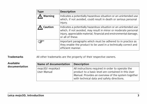
Type Description
�Danger Indicates an imminently hazardous situation which, if not avoided, will result in death or serious personal injury.
Leica mojo3D, Introduction 3
Trademarks All other trademarks are the property of their respective owners.
Available documentation
�Warning Indicates a potentially hazardous situation or an unintended use which, if not avoided, could result in death or serious personal injury.
�Caution Indicates a potentially hazardous situation or an unintended use which, if not avoided, may result in minor or moderate personal injury, appreciable material, financial and environmental damage, or all of these.
Important paragraphs which must be adhered to in practice as they enable the product to be used in a technically correct and efficient manner.
Type Description
Name of documentation Description
mojo3D/ mojoXact User Manual
All instructions required in order to operate the product to a basic level are contained in this User Manual. Provides an overview of the system together with technical data and safety directions.

4Leica mojo3D, Table of Contents
Table of ContentsIn this manual Chapter Page
1 System Overview 12
1.1 General mojo3D System Information 121.2 Components of the mojo3D System 131.3 Features and Specifications 15
1.3.1 mojo3D Hardware 151.3.2 mojo3D Software 171.3.3 mojo3D Positioning 171.3.4 mojo3D Guidance 181.3.5 mojo3D Section Control and Mapping 18
2 System Installation 20
2.1 Before Installation 202.2 mojo3D Installation 222.3 Antenna Installation 252.4 SIM Card Installation 29
3 Running the mojo3D for the First Time 32
3.1 Starting Up 323.2 Setting the Screen Calibration 34

Leica mojo3D, Table of Contents 5
3.3 Initial Setup Wizard 353.4 Menu Buttons at Right of Screen 493.5 Menu Buttons at Left of Screen 513.6 Specifying Data for Display 523.7 Zoom Buttons 543.8 View Modes 553.9 Error Notifications 563.10 Running the Setup Wizard at any Time 603.11 Changing System Settings 613.12 Vehicle Setup 623.13 Attached Device Selection 633.14 NMEA Configuration 653.15 Feature Unlock 66
4 Setting Guidance Types 68
4.1 AB Parallel Guidance 684.2 A+ Heading Guidance 704.3 Fixed Contour Guidance 724.4 Pivot Guidance 744.5 Ultimate Curve Guidance 764.6 Stop Guidance 794.7 Guidance Management 80
4.7.1 Saving a Wayline 804.7.2 Changing the Name of a Wayline 81

6Leica mojo3D, Table of Contents
4.7.3 Deleting an Individual Wayline 824.7.4 Deleting All Waylines 834.7.5 Exporting Waylines 854.7.6 Importing Waylines 904.7.7 Replay Guidance 97
4.8 Field Offset 994.9 Nudge 101
5 Auto-Steer 102
5.1 Engage Auto-Steer 1025.2 Tuning Auto-Steer Performance 106
5.2.1 Tuning Procedure 1065.2.2 Sensitivity 1095.2.3 Aggressiveness 1105.2.4 Overshoot 1115.2.5 Speed Adjust 1125.2.6 Tuning Tips 1135.2.7 Swap Left and Right Steering Control 115
5.3 Stationary Engage and Reverse Steering 1175.4 Testing Auto-Steer 123
6 Treatments 128
6.1 Starting a New Treatment 1296.2 Load a Stored Treatment 130

Leica mojo3D, Table of Contents 7
6.3 Changing a Treatment Name 1316.4 Creating a PDF Report of a Treatment 1326.5 Deleting a Treatment 1346.6 Exporting Treatment Data 1366.7 Importing Treatment Data 142
7 Automatic Section Control 146
7.1 Section Control Latency 1477.1.1 Calibrating the Section Control Latency Value 1487.1.2 Troubleshooting Latency Problems 150
7.2 Setting the Overlap Limit 1537.3 Setting the Low-Speed Shutoff 1557.4 Section Override Control 157
8 Field Boundary 158
8.1 Create a New Field Boundary 1588.2 Load a Stored Field Boundary 1608.3 Changing a Field Boundary Name 1618.4 Deleting a Field Boundary 1628.5 Exporting Field Boundary Data 1638.6 Importing Field Boundary Data 169
9 Vehicles and Implements 178
9.1 Saving a Vehicle or Implement Configuration 179

8Leica mojo3D, Table of Contents
9.2 Load a Vehicle or Implement Configuration 1819.3 Renaming a Vehicle or Implement Configuration 1839.4 Deleting Vehicle or Implement Configurations 1869.5 Exporting Vehicle or Implement Configurations 1919.6 Importing Vehicle and Implement Configurations 195
10 Correction Sources 202
10.1 Network DGPS 20310.2 SBAS 20910.3 GL1DETM 21110.4 Network RTK 21510.5 RTK Base Station (Internal Radio) 221
11 NMEA Output 226
11.1 Configuring NMEA Output 22711.2 Logging NMEA Data to USB 23011.3 NMEA Sentences Available 232
12 Virtual Wrench™ Remote Service 234
12.1 Virtual Wrench™ 23412.2 Making a Service Request 23512.3 Upgrading Software from Virtual Wrench™ 23612.4 Upgrading Software via USB Flash Drive 23812.5 Restoring Previous Software Version 240

Leica mojo3D, Table of Contents 9
12.6 Backing Up Current Software 24212.7 Serial Numbers and Other System Information 244
13 Care and Transport 246
13.1 Transport 24613.2 Storage 24613.3 Cleaning and Drying 247
14 Safety Directions 248
14.1 General Introduction 24814.2 Intended Use 24914.3 Limits of Use 25114.4 Responsibilities 25114.5 Hazards of Use 25314.6 Electromagnetic Compatibility (EMC) 25914.7 FCC Statement, Applicable in U.S. 26214.8 ICES-003 Statement, Applicable in Canada 26314.9 Labelling 264
15 Technical Data 268
15.1 mojo3D Display Technical Data 26815.2 mojo3D GPS Receiver Technical Data 27115.3 Wireless Modules Technical Data 273
15.3.1 HSDPA Wireless Module Technical Data 273

10Leica mojo3D, Table of Contents
15.3.2 CDMA Wireless Module Technical Data 27515.4 Antennas Technical Data 277
15.4.1 GPS Patch Antenna Technical Data 27715.4.2 Cellular Antenna Technical Data 28015.4.3 mojoXact and mojoXact Plus Red Antenna Technical Data 28215.4.4 mojoXact Black GeoPRO Antenna Technical Data 286
15.5 mojoXact Technical Data 28915.6 mojoXact GPS Receiver Technical Data 29215.7 mojoXact Plus Technical Data 29415.8 mojoXact Plus GPS Receiver Technical Data 29715.9 Conformity to National Regulations 299
15.9.1 mojo3D 29915.9.2 mojoXact 30115.9.3 mojoXact Plus 303
16 International Limited Warranty, Software License Agreement 306
Appendix A mojo3D Enhancements 308
A.1 mojo3D with Single Section Control 308A.2 mojo3D with Multi Section Control Kit 313A.3 mojo3D with GeoPRO Antenna 320A.4 mojo3D with mojoXact Kit 325
A.4.1 Leica mojoXact 326A.4.2 Installation 327

Leica mojo3D, Table of Contents 11
A.4.3 Antenna Installation 329A.4.4 Leica mojoXact Installation 334
A.5 Redeeming a System Option Voucher 364
Appendix B Formatting USB Flash Drives 366
Appendix C GNU General Public License 372
Appendix D Glossary of Terms 374

12Leica mojo3D, System Overview
1 System Overview
The images in this manual are for reference purposes only. Individual screens and icons may differ from the actual items.
1.1 General mojo3D System Information
General informa-tion
• Leica Geosystems' mojo3D is a GPS-based agricultural guidance system that provides visual guidance and mapping with optional auto steering and section control.
• Beyond its capabilities of visual or auto steer guidance and section control the mojo3D also provides remote service and diagnostics and remote upgrades via Virtual Wrench, thus reducing costly on-site service calls.

Leica mojo3D, System Overview 13
1.2 Components of the mojo3D System
mojo3D compo-nents
a) RAM mount - ballb) RAM mount - armc) mojo3D displayd) Glass-mount cell modem antennae) Magnetic-mount GPS antennaf) Standard power cableg) Product documentation
a
d
e
fg
mojo3D_001
b
c
14Leica mojo3D, System Overview
mojo3D accessory options
• Port expansion cable• Multi-Section control kit• Electric auto-steer kit• mojoRTK console• mojoRTK external control cable• mojoXact• GeoPRO antenna
Refer to "Appendix A mojo3D Enhancements" for more information about the acces-sory options, their installation and use.

Leica mojo3D, System Overview 15
1.3 Features and Specifications1.3.1 mojo3D Hardware
mojo3D hardware features
• Simple installation, with RAM mount and colour-coded quick-install antennas• Integrated L1 GPS receiver• Integrated cell modem, CDMA or HSDPA depending on region ordered• 12 volt operation• Internal storage for waylines, worked areas, and settings
a) USB interface for data transferb) Power buttonc) 7" colour touch screend) Port expansion connectore) Connector for GPS antenna, bluef) Connector for cell modem antenna,
purpleg) Power connectorh) Cover for SIM card sloti) RAM mount - ball
a cb
g
d e f
h i
mojo3D_002

16Leica mojo3D, System Overview
�Caution Operation by touch screen:The mojo3D is designed to be used by a finger tapping the display screen. It may affect warranty if operated with a hard object i.e. stylus or pen.

Leica mojo3D, System Overview 17
1.3.2 mojo3D Software
mojo3D software features
• Intuitive software that allows for easy setup and use• On screen field guidance and coverage mapping• Auto-steer compatible• Multi & single automatic section control• Upgrade, backup, and rollback of software through USB• Virtual Wrench™, which provides remote support and over-the-air software
upgrades
1.3.3 mojo3D Positioning
mojo3D posi-tioning features
• GPS algorithms are tuned for the agricultural environment.• Multi-link implement modelling, to provide high accuracy recording of worked
areas.• Optional NMEA (NMEA 0183) output for auxiliary devices that require GPS data.• Optional Radar-out signal for auxiliary devices that require a radar speed signal.• Leica Twist compatible for terrain compensated electric auto steer.• Leica mojoRTK Console or mojoXact compatible for base station RTK, Network
RTK, and Dual Frequency GL1DE™.

18Leica mojo3D, System Overview
1.3.4 mojo3D Guidance
mojo3D guidance features
• Multiple guidance patterns for visual guidance, including AB Parallel, A+ Heading, Fixed Contour, Pivot and Ultimate Curve.
• View in 3D perspective, with heads-up, chase, top-down, and north-up modes.• On-screen lightbar with heading assist operation.• Electric auto-steer capable, with Electric Steer Kit.• Hydraulic auto-steer capable, with Leica mojoRTK Console or Leica mojoXact.
1.3.5 mojo3D Section Control and Mapping
mojo3D section control and mapping features
• Single-section control using port expansion cable• Multi-section control capability with Multi-Section Kit• Direct Section Control capability with Direct Section Kit• Recording of worked area, with the ability to export PDF reports to a USB Flash
Drive for archiving

Leica mojo3D, System Overview 19

20Leica mojo3D, System Installation
2 System Installation2.1 Before Installation
General installa-tion information The installer must read and study this user manual, including the safety
directions. The installer must be able to use the system in accordance with the user manual. Leica Geosystems recommends that installation of the mojo3D equipment be performed by a qualified technician, because instal-lation requires making electrical connections.
• The following instructions are to be used as a general guide during the installa-tion of the mojo3D.
• The system will not operate at peak performance if steering joints and linkage assemblies are not within the manufacturer's specifications. Check for worn steering components by turning the steering wheel. As the steering wheel is turned, the wheels should begin to move. If results are undesirable, please consult your vehicle manufacturers’ maintenance manual.
• Install the system in a clean and dry workshop environment. Failure to do so may cause the system to short or promote product malfunction. Any moisture on the roof of the vehicle will also prevent the antenna mounting tape from sticking properly.
• Route and secure all cables and wiring to ensure that they do not chafe or rub, causing premature failure.

Leica mojo3D, System Installation 21
• The average installation time will vary, but it should be approximately two to four hours per vehicle. The time of installation may be more or less, based on vehicle type and options purchased.

22Leica mojo3D, System Installation
2.2 mojo3D Installation
RAM mount and mojo3D display installation
Select an appropriate place to mount the mojo3D display. The display needs to be within easy reach of the operator when seated in the normal operating position, and ideally it will be easily visible in the forward field of vision of the operator.
1. Mount the RAM mount ball to the vehicle in the required location. Use extreme caution whenever drilling holes or attaching any objects to the vehicle as there may be hidden cables or hoses. Never drill into the ROPS (roll over protection system) of any vehicle as this may damage the integrity of the system. Consult the vehicle’s operating manual prior to drilling any holes.
2. Connect the RAM mount arm and the mojo3D display to the mounting point.
3. Once the display is situated in the correct position suitable for the operator, ensure the RAM mount is tightly secured.
1 2
2
mojo3D_006

Leica mojo3D, System Installation 23
�Warning Do not mount the mojo3D where it may obscure the driver’s view of the road or field.
�Warning Do not mount the mojo3D where it may be struck by a deploying airbag.
Power cable instal-lation
1. Connect the supplied power cable to a reliable power source, for example, the vehicle’s main power system.• Connect the red wire to a 12-volt positive source, capable of delivering a
constant 2 A.• Connect the black wire to the vehicle’s earth.• Optional: Connect the orange wire to the vehicles switched ignition power
source to automatically power the mojo3D on and off with the vehicle's key.2. Route and secure all cables and wiring to ensure that there is no chafing or
rubbing, which can cause premature failure.3. Connect the power cable to the power
connector on the rear of the mojo3D display.
mojo3D_007

24Leica mojo3D, System Installation
The mojo3D is a 12-volt DC (negative-to-earth) system only.
Master input The optional master input on the mojo3D power cable may be connected to an external switch for remote operation of the Master Record Status button which starts and stops coverage recording on screen.
The master input should be 12 V when on and ground or floating when off.

Leica mojo3D, System Installation 25
2.3 Antenna Installation
Preparations 1. Read all instructions before assembly and installation.2. Clean the cab roof to prepare for the installation of the antennas. Approved
cleaning products are denatured alcohol and Windex® glass cleaner.
mojo3D GPS antenna
The mojo3D GPS antenna should be mounted on the vehicle roof:• on the centre line of the implement, which may not necessarily be the centre of
the vehicles roof• as far forward as possible on the flat level part of the roof• not obstructed by exhausts, flashing lights or any other objects
1. Use the supplied cleaning wipes to clean the installa-tion area.
2. Make sure that the installa-tion area is clean and dry.
3. Mount the GPS antenna on the roof of the vehicle. Use the adhesive tape provided.
1
3
mojo3D_004
26Leica mojo3D, System Installation
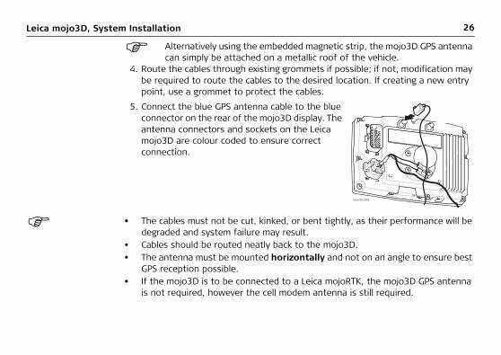
Alternatively using the embedded magnetic strip, the mojo3D GPS antenna can simply be attached on a metallic roof of the vehicle.
4. Route the cables through existing grommets if possible; if not, modification may be required to route the cables to the desired location. If creating a new entry point, use a grommet to protect the cables.
• The cables must not be cut, kinked, or bent tightly, as their performance will be degraded and system failure may result.
• Cables should be routed neatly back to the mojo3D.• The antenna must be mounted horizontally and not on an angle to ensure best
GPS reception possible. • If the mojo3D is to be connected to a Leica mojoRTK, the mojo3D GPS antenna
is not required, however the cell modem antenna is still required.
5. Connect the blue GPS antenna cable to the blue connector on the rear of the mojo3D display. The antenna connectors and sockets on the Leica mojo3D are colour coded to ensure correct connection.
mojo3D_008

Leica mojo3D, System Installation 27
mojo3D cell radio antenna
The mojo3D cell radio antenna can be mounted directly on the inside of the vehicle cabin glass,• at least 5 cm (2") from the surrounding
metal frame.• no closer than 20 cm (8") to the oper-
ator's normal driving position.• Check that placement of antenna does
not interfere with users field of vision.
mojo3D_005
5cm
28Leica mojo3D, System Installation
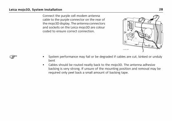
• System performance may fail or be degraded if cables are cut, kinked or unduly bent
• Cables should be routed neatly back to the mojo3D. The antenna adhesive backing is very strong. If unsure of the mounting position and removal may be required only peel back a small amount of backing tape.
Connect the purple cell modem antenna cable to the purple connector on the rear of the mojo3D display. The antenna connectors and sockets on the Leica mojo3D are colour coded to ensure correct connection.
mojo3D_009

Leica mojo3D, System Installation 29
2.4 SIM Card Installation
To enable Virtual Wrench™ on systems equipped with a HSDPA internal modem a SIM Card from a suitable service provider is required.
1. Place mojo3D face down on a work-bench.
2. Remove the two screws and open the cover for the SIM card slot.
3. Use a pointed instrument to press the release mechanism.
4. Slide out the SIM card holder.5. Put SIM card into SIM card holder, with
the chip facing up, ensuring that the SIM card is securely seated in the holder.
6. Insert the SIM card holder back into the SIM card slot.
7. Replace the cover, and replace screws to secure. mojo3D_003
2
3
4
5

30Leica mojo3D, System Installation
�Caution The mojo3D must remain face down on a workbench when inserting a SIM card to remove the possibility of the SIM card being dropped inside the mojo3D.
When the mojo3D is turned on the cell phone icon should appear with signal strength.

Leica mojo3D, System Installation 31

32Leica mojo3D, Running the mojo3D for the First Time
3 Running the mojo3D for the First Time3.1 Starting Up
Starting up, step-by-step
1. To start the mojo3D, press and hold the power button for two seconds.
2. The splash screen appears on the mojo3D display, and is replaced by the warning signs screen, shown below.The warning signs are to communicate to the operator that:• riding on the machine is only allowed on a passenger seat, • the User Manual must have been read prior to operation and • to keep a safe distance away from people and other hazards. The startup progress bar at the bottom of the screen indicates the progress of the system initialisation procedure.

Leica mojo3D, Running the mojo3D for the First Time 33
3. Once system initialisation is complete, the screen calibration icon appears in the top left-hand corner of the screen. This icon is used to set the screen cali-bration. Refer to "3.2 Setting the Screen Calibration" for more information.

34Leica mojo3D, Running the mojo3D for the First Time
3.2 Setting the Screen Calibration
General informa-tion
Differences may exist between different devices, and so the screen calibration must be set before operation.
Setting the screen size, step-by-step
1. Tap - with your finger, not an object - the middle of the screen calibration icon, which is in the top left-hand corner of the screen. The icon will appear in another position. Continue to tap the middle of each icon until the corners and centre of the screen are defined. You will need to tap the screen five times.
2. The Initial Setup Wizard appears on the screen. Tap at the bottom of the screen to continue with the initial setup.
If required, Screen Calibration can be updated anytime while the mojo3D is powered on by holding the power button for 8 seconds, release the power button to display the screen calibration screen. If the power button is held for more than 15 seconds the mojo3D will turn off.

Leica mojo3D, Running the mojo3D for the First Time 35
3.3 Initial Setup Wizard
General informa-tion
• The attached device, language used in displays, screen brightness, country, units of length and speed, display mode, lightbar mode, cell modem setup, and vehicle and implement setups must be configured.
• The attached device selection screen is the first initial setup screen to appear.
Attached device selection, step-by-step
1. On the attached device selection screen, tap the button that describes your hardware setup.• mojo3D
(button at top left of screen)
• mojo3D with Leica mojoXact/mojoXact Plus(button at bottom right of screen)
2. Tap to continue.
• If the mojo3D option was selected the brightness screen appears.• If another option was selected, then the configuration setup for the selected
device is displayed.
Refer to "Appendix A mojo3D Enhancements" for more information on the setup of the other devices.

36Leica mojo3D, Running the mojo3D for the First Time
Brightness adjust-ment, step-by-step
1. Adjust the slider to vary the brightness of the screen, by tapping and .
2. Tap to continue.
Country selection, step-by-step
1. On the country selection screen, tap the button labelled with the flag of your country. Countries are listed in alphabetical order on the screen. If the required
flag is not visible, tap to display more flags.
2. After making your selection, tap to continue.
Language selec-tion, step-by-step
1. On the languages screen, tap the button labelled with your required language.
2. Tap to continue.
Time specification, step-by-step
1. On the UTC Time screen, tap and to enter the local time, expressed as an offset from UTC (Coordinated Universal Time) time. Each tap will change the time offset by 30 minutes.
2. After selection, tap to continue.
Units selection, step-by-step
1. On the units selection screen, tap the buttons to select:• Lengths may be measured in metric, Imperial, or US Standard units. • Speeds may be measured in metric, Imperial, or US Standard units.

Leica mojo3D, Running the mojo3D for the First Time 37
• Areas may be measured in metric, Imperial, or US Standard units. The Imperial acre is the defined international acre, and the US acre is the slightly smaller US Survey acre.
2. After making your selections, tap to continue.
Mode selection,step-by-step
1. On the mode selection screen, tap the buttons to select:• top-down mode: either north is at the top of the map screen, or the direction
of the front of the vehicle is at the top of the map screen, and• display mode: day mode, night mode, or automatic switch between modes.
2. After making your selections, tap to continue.
Lightbar mode setup, step-by-step
The default lightbar mode is the Leica Geosystems Smart lightbar which uses both cross track error and heading error to guide you to the line. The other choice offered is the traditional Crosstrack only lightbar.
To configure the lightbar settings, carry out the following steps:
1. On the Lightbar Mode screen, select:• Smart to use the smart lightbar, or• Crosstrack to use the traditional cross track lightbar.
2. If you selected Smart, tap to continue through the System Settings Wizard.

38Leica mojo3D, Running the mojo3D for the First Time
3. If you selected Crosstrack, more configuration options are now available on the Lightbar Mode screen. • Chase: when Chase mode is on (green), the lightbar represents where the line
is relative to where the vehicle is, and to steer to the line, you steer towards the light - that is, you chase the light. When Chase mode is off (gray) the lightbar represents the position of the vehicle relative to the line and to steer the vehicle onto the line, you steer away from the light to "pull" the light to the line.
• Crosstrack error per lightbar segment: this setting determines how much cross track error is represented by each segment in the lightbar. A small number makes the lightbar more sensitive and hard to follow, but more accu-rate. A large number makes the lightbar less sensitive and easy to follow, but less accurate.
Choose your lightbar settings.
4. Tap to continue through the System Settings Wizard.
Cell modem setup,step-by-step
The mojo3D allows the operator to choose whether to enable or disable the cell modem.
A Network Data plan for the mojo3D and a SIM card with an active data plan are required before you can utilize the online features of the mojo3D. Contact your dealer to obtain the required unlock vouchers.

Leica mojo3D, Running the mojo3D for the First Time 39
The cell modem is enabled or disabled by checking or unchecking the Enable Cell Modem checkbox. If the Enable Cell Modem box is checked, the operator may be required to enter further information. This information is available from your cellular network provider.
Depending on the region purchased, this information may be pre-selected. If this is the case, this screen will not be displayed.
APN, Username and Password can be obtained by contacting the network provider for the SIM card.
• APN Field1. Tap the APN (Access Point Name) field. The on-screen keyboard appears.2. Tap the keys on the on-screen keyboard to enter the name.
• Username Field1. Tap the Username field. The on-screen keyboard appears.2. Tap the keys on the on-screen keyboard to enter the user name.
Tap the keyboard selection button, at the bottom left of the on-screen keyboard, to select keyboards with numbers and punctuation, or Cyrillic letters.
3. Tap on the on-screen keyboard.
40Leica mojo3D, Running the mojo3D for the First Time
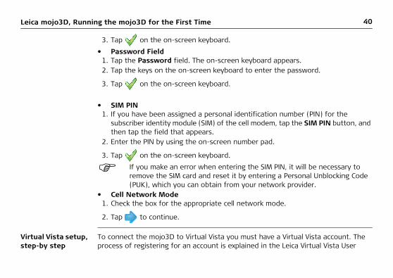
3. Tap on the on-screen keyboard.
• Password Field1. Tap the Password field. The on-screen keyboard appears.2. Tap the keys on the on-screen keyboard to enter the password.
3. Tap on the on-screen keyboard.
• SIM PIN1. If you have been assigned a personal identification number (PIN) for the
subscriber identity module (SIM) of the cell modem, tap the SIM PIN button, and then tap the field that appears.
2. Enter the PIN by using the on-screen number pad.
3. Tap on the on-screen keyboard.
If you make an error when entering the SIM PIN, it will be necessary to remove the SIM card and reset it by entering a Personal Unblocking Code (PUK), which you can obtain from your network provider.
• Cell Network Mode1. Check the box for the appropriate cell network mode.
2. Tap to continue.
Virtual Vista setup, step-by step
To connect the mojo3D to Virtual Vista you must have a Virtual Vista account. The process of registering for an account is explained in the Leica Virtual Vista User

Leica mojo3D, Running the mojo3D for the First Time 41
Manual. The result of this registration process is a user name and a password which are needed in the steps below.1. To enable Virtual Vista, tap the Use Virtual Vista check box.2. Enter the user name (email address) and password used to set up your Virtual
Vista account.
3. Tap to continue.
The Virtual Vista connection status is shown in the top left system status area.
indicates that the connection is successful and indicates that a
connection error has occurred.
Vehicle setup, step-by-step
1. On the Vehicle setup screen, tap the vehicle type in the list at the left of the
screen. Tap and to reveal more options.
2. Enter the measurements required for the vehicle type that you have selected.• Tap on a field. The on-screen keyboard appears.
• Use the on-screen keyboard to enter the measurement, tap to continue.
• Repeat for the other measurements required.3. After you have entered all required vehicle measurements, add any required
implements on the same screen. If no implements are required, tap to continue.

42Leica mojo3D, Running the mojo3D for the First Time
Implement setup, step-by-step
To add an implement carry out the following steps:
3. Enter the measurements required for the implement type that you have selected.• Tap on a field. The on-screen keyboard appears.
• Use the on-screen keyboard to enter data, tap to continue.
• Repeat for all measurements required.
4. If more implements are required, tap to add another implement. To change settings for the vehicle or implements already set up, tap the relevant button in the top bar.
5. After you have entered all the required settings, tap to continue.
1. On the vehicle setup screen, tap . An implement button appears in the bar at the top of the screen and the list of implement types are shown.
2. Tap the implement type in the list at the left of the screen. Tap and to reveal more options.

Leica mojo3D, Running the mojo3D for the First Time 43
Section controller implement mode setup, step-by-step
1. On the section controller/implement mode setup screen, in the list at the left of the screen, tap to select section controller type:• None: section control is disabled.• On Screen: sections are shown on screen turning on & off, but no physical
control of sections is possible.• Single Section: a maximum of one section can be setup for the vehicle. This
section is automatically controlled with physical output on the port expansion cable.
• Leica AS400: multiple sections are automatically controlled via the Leica AS400 section controller hardware, supplied with the multi-section control kit.
If Direct Section Control has been unlocked, other Section Controllers will appear in the list.
2. Tap to select implement mode:• Sprayer Mode: is used for most situations, this allows the section control to
be optimally setup for general applications.• Planter Mode: optimises the system for operating a planter and if selected,
reverses the polarity of the Leica AS400 normal operation.
3. Tap to continue.
Master input source setup, step-by-step
1. On the master input source screen, in the list at the left of the screen, tap to select the master input source.
2. In the list at the right of the screen, tap to select the input mode.

44Leica mojo3D, Running the mojo3D for the First Time
The Master Input Source & Input Mode options available will depend on the configuration of the individual system:
• mojo3D / Touch: the on screen coverage mapping is activated by touching the Master Record button on the screen.
• mojo3D / Master Input: the on screen coverage mapping is activated by sensing a voltage connected to the Master wire on the mojo3D power cable.
• Leica AS400 / Single: the on screen coverage mapping is activated by sensing a voltage connected to the Master wire on the Leica AS400 controller port. This is only available with specific rate controller cables.
• Leica AS400 / Dipole Switch: the on screen coverage mapping is activated by sensing a pair of switching wires. This is only available with specific rate controller cables.
3. Tap to continue.
Section control setup, step-by-step
1. The section control setup screen initially shows one section, as a single blue bar near the top of the screen. To set the number of sections, tap the number of
sections field, enter the number of sections, and tap .
2. The blue bar will be divided showing the number of sections set. To set the width of the first section, tap the section width field, enter the width measurement

Leica mojo3D, Running the mojo3D for the First Time 45
and tap . The minimum value accepted for a section width is 12 inches or 30 centimetres.
3. Tap at the top right corner of the screen, the selected section in the bar will be coloured blue. Set the width of the section the same way by tapping on the section width field.
When all sections widths are correctly set, the Implement Width shown should match the total width of the physical implement.
4. If automatic section control is being used, then additional information will have to be entered.• Overlap limit: the percentage amount of overlap that is to be allowed before
the section is turned off.• Low Speed Shutoff: the minimum travel speed for a section before it is
turned off.• Off latency: the number of seconds it takes from the section being turned off
until the actual application stops.• On latency: the number of seconds it takes from the section being turned on
until the actual application starts.
Refer to "7 Automatic Section Control" for more detail on the individual settings.
5. When you have entered all required data tap to continue.

46Leica mojo3D, Running the mojo3D for the First Time
Correction source configuration, step-by step
1. On the Correction Source screen, select the correction source to use for your system.
2. Tap to continue.
• If Network DGPS is selected, further configuration is required and this is described in "10.1 Network DGPS". Once the configuration is complete, the NMEA Configuration screen displays.
• If GL1DETM Only is selected, no extra configuration is required, so the NMEA
Configuration screen displays when the button is tapped.
NMEA configura-tion If NMEA output is not required tap to complete the initial setup.
If NMEA output is required from the mojo3D, follow the detailed informa-tion in "11 NMEA Output".

Leica mojo3D, Running the mojo3D for the First Time 47
Main navigation screen
Once the Initial Setup Wizard is complete the main navigation screen is displayed:
Primarily status information is displayed on the left hand side.
The buttons down the right hand side ofthe display are the main buttons used
to navigate through the system.

48Leica mojo3D, Running the mojo3D for the First Time
If the menu buttons on the left or the right side of the main navigation screen have not been touched for 20 seconds, they fade away to provide a larger view of the field, as shown below. The buttons fade in a way that the field behind is very easy to see but the buttons can still be identified. When one of the buttons on the left or the right is tapped, all of the buttons return to their totally visible state.

Leica mojo3D, Running the mojo3D for the First Time 49
3.4 Menu Buttons at Right of Screen
Menu buttons at right of screen
The menu buttons on the right of the main navigation screen are:
Service
Tap on these buttons to display a menu. These menus are referred to as flyout menus. An example of a flyout menu is shown on page 50.
Mapping
Guidance
Settings
Auto-steer Settings If the mojo3D is being used without
additional auto-steer options, then the Auto-steer Settings button and the Auto-steer button will be disa-bled.
Auto-steer

50Leica mojo3D, Running the mojo3D for the First Time
Flyout Menu Example

Leica mojo3D, Running the mojo3D for the First Time 51
3.5 Menu Buttons at Left of Screen
Menu buttons at left of screen
The menu buttons at the left of the screen are:
StatusTap the status button to display a screen with status information and errors for:
• Base station (if used)• Satellites visible• Cell modem signal strength• Virtual Wrench™ (if connected)Five buttons with
user-selected data.Refer to see "3.9 Error Notifications" for more information.
Master record status

52Leica mojo3D, Running the mojo3D for the First Time
3.6 Specifying Data for Display
Specifying data for display, step-by-step
The items displayed at the left of the main navigation screen may be selected by the user. To specify the items for display, carry out the following steps:1. Tap any of the data items in the left-hand menu on the main navigation screen.
The Status item selection screen appears:

Leica mojo3D, Running the mojo3D for the First Time 53
2. In each column, tap an item for display. Left-to-right order on this screen trans-lates to top-to-bottom order on the main navigation screen.• Tap Total Area to select the total area enclosed by the field boundary to be
displayed.• Tap Remaining to select the approximate area remaining within the field
boundary to be displayed.
The area remaining is calculated as the total field boundary area less the recorded amount of coverage excluding overlap. The remaining area may not be accurate if large amounts of area has been covered outside the field boundary.
3. To set the odometer display to zero, tap the reset odometer button at the right of the screen.
4. Tap to return to the main navigation screen.

54Leica mojo3D, Running the mojo3D for the First Time
3.7 Zoom Buttons
Using zoom buttons, step-by-step
To use the zoom buttons, carry out the following steps:• To display the zoom buttons, touch the middle of the screen, the zoom buttons
will appear on the main navigation screen.
• To zoom in, tap .
• To zoom out, tap .• To zoom continuously in or out, tap and hold the appropriate button.The mojo3D remembers the current zoom level when it is shutdown, so when it is restarted the same zoom level is displayed.

Leica mojo3D, Running the mojo3D for the First Time 55
3.8 View Modes
View modes There are four different view modes available:• First person: zoomed-in as far as possible.• Chase: behind the triangle or three-dimensional vehicle icon.• Top down (north up): a view from above the vehicle where map is shown with
north always at the top of the screen.• Top down (heads up): a view from above the vehicle with map shown from the
drivers point of view forwards.The mojo3D remembers the current view mode when it is shutdown, so when it is restarted the same view mode displays.
Changing the view mode, step-by-step
To change the view mode between First person, Chase and Top down, carry out the following steps:1. Touch the middle of the screen, to display the zoom buttons.
2. Tap either or repeatedly, until the view mode changes.
To change between Top Down North Up and Top Down Heads Up refer to "3.11 Changing System Settings".

56Leica mojo3D, Running the mojo3D for the First Time
3.9 Error Notifications
General informa-tion
When any error occurs, the background of the status button goes red. To view information about the error tap the button.At any time the complete list of recent errors can be viewed.
A brief description of any error that is currently active, or was active in the last 10 seconds, is displayed at the bottom of the main navigation screen, as shown below.

Leica mojo3D, Running the mojo3D for the First Time 57
Viewing errors, step-by-step
To view the list of recent errors, carry out the following steps:
If there is more than one error active, brief descriptions of the errors cycle at 2 second intervals at the bottom of the main navigation screen.
Critical errors are shown as blocking messages, where the operator must acknowledge and address the error before normal operation can continue.
Details of errors can be displayed by following the directions below.
1. On the main navigation screen, tap the Status button.
2. For an overview of status information, like number of satellites, cell modem signal strength, or steering kit status, tap the Over-view button.
3. For a list of local errors, tap the local errors button.
4. Tap on an error in the list to display more information.

58Leica mojo3D, Running the mojo3D for the First Time
Viewing position status, step-by-step
The Position Status screen provides information that is helpful when troubleshooting position related problems.To view the position status information, carry out the following steps:
5. If an external device that supports error reporting is attached tap the remote errors button for a list of remote errors.
6. Tap to return to the main navigation screen.
1. On the main navigation screen, tap the status button.
2. To view the position status information, tap the position status button.The Position Status screen, shown below, displays.

Leica mojo3D, Running the mojo3D for the First Time 59
3. To return to the main navigation screen, tap the button.

60Leica mojo3D, Running the mojo3D for the First Time
3.10 Running the Setup Wizard at any Time
General informa-tion
The initial setup wizard can be run again at any time after the initial setup.The wizard guides you through the whole system setup: System Setup, Vehicle Setup, Attached Device Selection, NMEA Configuration. Alternatively you are able to setup specific sections separately via the appropriate setup button.
Running the setup wizard, step-by-step
To run the Setup Wizard, carry out the following steps:
All changes are automatically saved as they are made.
1. On the main navigation screen, tap the Settings button.
2. On the flyout menu, tap the setup wizard button.
3. On the attached device selection screen, tap the icon that describes your setup, for example mojo3D button.
4. Tap to continue through the setup wizard. Make any changes that are required.
For specific information on the different settings refer to "3.3 Initial Setup Wizard".

Leica mojo3D, Running the mojo3D for the First Time 61
3.11 Changing System Settings
General informa-tion
The system settings includes:
Changing settings, step-by-step
To select and change one of these items, carry out the following steps:
All changes are automatically saved as they are made.
• Screen brightness• Country• Language• Time offset
• Measure units (length, speed & area)• Top down mode• Display (day/night) mode• Cell modem setup,
1. On the main navigation screen, tap the Settings button.
2. On the flyout menu, tap the system settings button.
3. Tap to continue through the system settings wizard. Make any changes that are required.
For specific information on the different settings refer to "3.3 Initial Setup Wizard".

62Leica mojo3D, Running the mojo3D for the First Time
3.12 Vehicle Setup
General informa-tion
Vehicle setup includes:• Vehicle & Implement setup• Section controller and Implement mode selection• Master Input & Input Mode selection• Swath and Section control setup
Vehicle setup, step-by-step
To select and change one of these items, carry out the following steps:
All changes are automatically saved as they are made.
1. On the main navigation screen, tap the Settings button.
2. On the flyout menu, tap the Vehicle setup button.
3. Tap to continue through the vehicle setup wizard. Make any changes that are required.
For specific information on the different settings refer to "3.3 Initial Setup Wizard".

Leica mojo3D, Running the mojo3D for the First Time 63
3.13 Attached Device Selection
General informa-tion
Attached device selection includes:• Selection of attached device:
• None (mojo3D is used as a standalone device)• Electric Steer Kit• Leica mojoRTK• Leica mojoXact/mojoXact Plus
• Configuration of attached device
Attached device selection, step-by-step
To select and change one of these items, carry out the following steps:1. On the main navigation screen, tap the Settings button.
2. On the flyout menu, tap the Attached device selection button.
3. On the attached device selection screen, tap the button that describes your setup, for example the Leica mojoXact Plus.

64Leica mojo3D, Running the mojo3D for the First Time
All changes are automatically saved when proceeding to the next screen.
4. Tap to continue through the attached device wizard. Make any changes that are required.
Refer to "Appendix A mojo3D Enhancements" for more information on these setups.

Leica mojo3D, Running the mojo3D for the First Time 65
3.14 NMEA Configuration
General informa-tion
NMEA configuration includes:• Configure serial port & NMEA messages• Log NMEA to USB• Advanced NMEA configuration
NMEA configura-tion, step-by-step
To select and change one of these items, carry out the following steps:
All changes are automatically saved as they are made.
1. On the main navigation screen, tap the Settings button.
2. On the flyout menu, tap the NMEA button.
3. Tap to continue through the NMEA wizard. Make any changes that are required.
For specific information on the different settings refer to "11 NMEA Output".

66Leica mojo3D, Running the mojo3D for the First Time
3.15 Feature Unlock
Feature unlock, step-by-step
For some configurations the feature unlock button may not be available. In cases where some features are locked, new authorisation codes can be entered using the feature unlock. Features can be unlocked using the steps below or Virtual Wrench as explained in "12 Virtual Wrench™ Remote Service".
To unlock a feature, carry out the following steps:1. On the main navigation screen, tap the Settings button.
2. On the flyout menu, tap the Features Settings button. The features status screen appears, with a list of features and their availability-locked or unlocked.
3. To activate a new feature, tap the Enter New Code button. Use the on-screen keyboard to enter the new code.
4. Tap to save settings and return to the main navigation screen.

Leica mojo3D, Running the mojo3D for the First Time 67
68Leica mojo3D, Setting Guidance Types
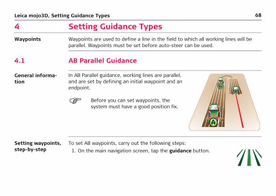
4 Setting Guidance TypesWaypoints Waypoints are used to define a line in the field to which all working lines will be
parallel. Waypoints must be set before auto-steer can be used.
4.1 AB Parallel Guidance
General informa-tion
Setting waypoints, step-by-step
To set AB waypoints, carry out the following steps:
In AB Parallel guidance, working lines are parallel, and are set by defining an initial waypoint and an endpoint.
Before you can set waypoints, the system must have a good position fix.
1. On the main navigation screen, tap the guidance button.

Leica mojo3D, Setting Guidance Types 69
5. On the dialog box that appears:
• tap to save the wayline to memory.
An on-screen keyboard appears. Enter a name for the wayline, and tap .OR
• tap to use the wayline without first saving it to memory.
2. On the flyout menu, tap the AB parallel guidance button.
3. Position your vehicle in the field at the point where you want to start (waypoint A), and tap the A point button.
4. Drive to your desired endpoint in the field (waypoint B), then tap the B point button.
The minimum distance between waypoints A and B is 30 metres (100 feet). The greater the distance between the waypoints, the better the accuracy of the working line. Where possible, set the waypoints at either end of the field.

70Leica mojo3D, Setting Guidance Types
4.2 A+ Heading Guidance
General informa-tion
Setting A+ heading guidance, step-by-step
To set up A+ heading guidance, carry out the following steps:
In A+ heading guidance, working lines are parallel, and are set by defining an initial waypoint and a compass bearing.
Before you can set waypoints, the system must have a good position fix.
1. On the main navigation screen, tap the guidance button.
2. On the flyout menu, tap the A+ heading guidance button.
3. Position your vehicle in the field at the point where you want to start (waypoint A), and tap the A point button.

Leica mojo3D, Setting Guidance Types 71
4. On the on-screen numeric keyboard, enter the heading (compass bearing) for
the wayline, and tap .
5. On the dialog box that appears:
• tap to save the wayline to memory.
An on-screen keyboard appears. Enter a name for the wayline, and tap .OR
• tap to use the wayline without first saving it to memory.

72Leica mojo3D, Setting Guidance Types
4.3 Fixed Contour Guidance
General informa-tion
Setting fixed contour guidance, step-by-step
To set up fixed contour guidance, carry out the following steps:
In fixed contour guidance, working lines are parallel curves, and are set by defining an initial contour with a beginning and an ending waypoint.
Before you can set waypoints, the system must have a good position fix.
1. On the main navigation screen, tap the guidance button.
2. On the flyout menu, tap the fixed contour guidance button.

Leica mojo3D, Setting Guidance Types 73
6. On the dialog box that appears:
• tap to save the wayline to memory.
An on-screen keyboard appears. Enter a name for the wayline, and tap .OR
• tap to use the wayline without first saving it to memory.
3. Position your vehicle in the field at the point where you want to start (waypoint A), and tap the A point button.
4. Drive along the contour. At least 30 m (100 feet) must be travelled before waypoint B can be entered.
To record a straight line segment: Tap to start the straight line, then tap to continue recording the contour.
5. Tap the B point button on screen when at the end of the contour to complete the recording.

74Leica mojo3D, Setting Guidance Types
4.4 Pivot Guidance
General informa-tion
Setting pivot guid-ance, step-by-step
To set up pivot guidance, carry out the following steps:
In pivot guidance, working lines are concentric circles and are defined by setting three waypoints.
Before you can set waypoints, the system must have a good position fix.
1. On the main navigation screen, tap the guidance button.
2. On the flyout menu, tap the pivot guidance button.
3. Position your vehicle in the field at the position where you want to start (waypoint A), and tap the A point button.
4. Drive to waypoint B, and tap the B point button.

Leica mojo3D, Setting Guidance Types 75
6. On the dialog box that appears:
• tap to save the wayline.
An on-screen keyboard appears. Enter a name for the wayline, and tap .OR
• tap to use the wayline without first saving it to memory.
5. Drive to waypoint C, and tap the C point button.

76Leica mojo3D, Setting Guidance Types
4.5 Ultimate Curve Guidance
Benefits Ultimate Curve guidance provides guidance alongside any previously recorded coverage. This means guidance can be provided around practically any irregular shaped field or back and forth along a complex contour line. As there is no need to pre-define a shape, Ultimate Curve guidance can be activated at anytime and guid-ance alongside any previous coverage will be provided.
General informa-tion
The minimum turn radius is the smallest radius that the vehicle and imple-ment can turn comfortably without doing damage to the vehicle or imple-ment. It is calculated by driving the vehicle with the implement attached in a circle. Measure the distance from the middle of the wheel tracks to the centre of the circle.
In Ultimate Curve guidance, working lines are parallel to the recorded coverage, and are created when the vehicle approaches a covered area with the guidance mode active.
There is no requirement to pre-define Ultimate Curve guidance before it can be used.

Leica mojo3D, Setting Guidance Types 77
Minimum turn radius configura-tion
To configure the vehicle for Ultimate Curve guidance, carry out the following steps:1. On the main navigation screen, tap the settings button.
2. On the flyout menu, tap the Vehicle setup button.
3. Tap to display the Minimum Turn Radius screen.
4. Tap the minimum turn radius value box.
5. Use the on–screen number pad to enter a value for the minimum turn radius.
6. Tap on the number pad to complete the value entry.
7. Tap to continue through the vehicle setup and return to the main navigation screen.

78Leica mojo3D, Setting Guidance Types
Setting Ultimate Curve guidance, step-by-step
To use Ultimate Curve guidance, carry out the following steps:
Waylines will automatically be created and updated as the vehicle continues back and forth or around the field.
1. On the main navigation screen, tap the master record button.
2. Drive the first pass or lap in the field and position the vehicle for the next pass.3. On the main navigation screen, tap the guidance button.
4. On the flyout menu, tap the Ultimate Curve button.
Leica mojo3D, Setting Guidance Types 79
4.6 Stop Guidance
General informa-tion
Guidance can be stopped to allow the operator a clear view of the screen when oper-ating in an environment where guidance is not required.
Stopping guid-ance, step-by-step
To turn off the display of guidance information, carry out the following steps:
1. On the main navigation screen, tap the guidance button.
2. On the flyout menu, tap the stop guidance button.
You are returned to the main navigation screen which is now clear of guidance information.

80Leica mojo3D, Setting Guidance Types
4.7 Guidance Management4.7.1 Saving a Wayline
Automatic saving Every time a wayline is set a dialog box is displayed which allows the line to be imme-
diately saved by tapping . The line can be used without first saving by tapping .
Save a wayline When a line is not saved immediately after being set, it can be manually saved:1. On the main navigation screen, tap the guidance button.
2. On the flyout menu, tap the wayline management button.
3. Tap the save button.
4. Use the on-screen keyboard to enter the name for the wayline, and tap .

Leica mojo3D, Setting Guidance Types 81
4.7.2 Changing the Name of a Wayline
General informa-tion
The name under which a wayline is stored on the mojo3D can be changed. The actual data in the wayline cannot be changed, only deleted.
Changing wayline name, step-by-step
To change the name of a stored wayline, carry out the following steps:1. On the main navigation screen, tap the guidance button.
2. On the flyout menu, tap the wayline management button.
3. Tap the name of the wayline that you wish to change, and then tap the edit button.
4. Use the on-screen keyboard to enter the new name for the wayline, and tap .

82Leica mojo3D, Setting Guidance Types
4.7.3 Deleting an Individual Wayline
General informa-tion
A wayline stored on the mojo3D can be deleted. Once a wayline has been deleted, it cannot be recovered, unless it has been backed up to a USB Flash Drive before.
Deleting a wayline, step-by-step
To delete a stored wayline, carry out the following steps:1. On the main navigation screen, tap the guidance button.
2. On the flyout menu, tap the wayline management button.
3. Tap the name of the wayline that you wish to delete, and then tap the delete button.
4. On the dialog box that appears:
• tap to confirm deletion.
OR
• tap to cancel the operation.
5. Tap to return to the main navigation screen.

Leica mojo3D, Setting Guidance Types 83
4.7.4 Deleting All Waylines
General informa-tion
All of the waylines stored on the mojo3D can be deleted simultaneously. Once the waylines have been deleted, they cannot be recovered, unless they have been backed up to a USB Flash Drive before.
Deleting all waylines, step-by-step
To delete all stored waylines, carry out the following steps:1. On the main navigation screen, tap the guidance button.
2. On the flyout menu, tap the wayline management button.
3. On the screen that lists the names of the waylines, tap the delete all waylines button.
4. On the dialog box that appears:
• tap to confirm deletion.
OR
• tap to cancel the operation.
84Leica mojo3D, Setting Guidance Types
5. Tap to return to the main navigation screen.

Leica mojo3D, Setting Guidance Types 85
4.7.5 Exporting Waylines
General informa-tion
Waylines can be exported to a USB Flash Drive. This is useful for copying the waylines to other mojo3D units. Waylines can be exported in the following formats:
• mojo3D files.• Google Earth kml files.• Shapefile shp, dbf, prj and shx files - which can be opened by other third party
applications.
Refer to "Appendix B Formatting USB Flash Drives" for important informa-tion about using USB drives with the mojo3D products.
Do not turn off the mojo3D, or remove the USB Flash Drive, while the wayline export is under way.
You can export mojo3D files or Google Earth files or Shapefile files.

86Leica mojo3D, Setting Guidance Types
Exporting waylines, step-by-step
To export all waylines stored in the mojo3D in a mojo3D file format, carry out the following steps:1. The USB interface is on the lower left front of the
mojo3D display. Lift the rubber cover and insert a compatible USB Flash Drive into the USB slot.
2. On the main navigation screen, tap the settings button.
3. On the flyout menu, tap the transfer data button.
4. Tap the export to USB button and tap to continue.
mojo3D_010

Leica mojo3D, Setting Guidance Types 87
If a mojoRTK is attached, waylines can be transferred from the mojo3D to the mojoRTK by tapping the button shown.
5. Tap the Guidance button and tap to continue.
If there are already waylines with the same name on the USB Flash Drive there will be a message to confirm overwriting the waylines.
6. On the dialog box that appears:
• tap to overwrite the waylines on the USB Flash Drive.OR
• tap to cancel the operation.
7. Tap to return to the main navigation screen.

88Leica mojo3D, Setting Guidance Types
Exporting Google Earth and Shapefile data for a selected wayline, step-by-step
To export Google Earth and Shapefile data for a selected wayline, carry out the following steps:1. The USB interface is on the lower left front of the
mojo3D display. Lift the rubber cover and insert a compatible USB Flash Drive into the USB slot.
2. On the main navigation screen, tap the guidance button.
3. On the flyout menu, tap the wayline management button.The Guidance Management screen appears.
4. Tap and to scroll though the list of waylines. To select the wayline to export, tap the wayline’s name.
mojo3D_010

Leica mojo3D, Setting Guidance Types 89
5. To export the selected wayline’s data, tap the export to USB button. (Note that the export button has the arrow pointing to the USB memory key.)
Depending on the size of the wayline, the export operation may take a minute or more.
If files already exist on the USB memory key with the same names as the wayline files being exported, a dialog displays a message to confirm the overwriting of the data.
6. To overwrite the existing data, tap the button.
To cancel the export operation, tap the button.
When the export of the wayline data is complete, a message displays stating that the data has been saved.
7. To close the message box and return to the wayline management
screen, tap the button.
8. To return to the main navigation screen, tap the button.

90Leica mojo3D, Setting Guidance Types
4.7.6 Importing Waylines
General informa-tion
Waylines in the following formats can be imported into a mojo3D: • mojo3D files.• Google Earth kml files.• Shapefile shp, dbf, prj and shx files.
Refer to "Appendix B Formatting USB Flash Drives" for important informa-tion about using USB drives with the mojo3D products.
Do not turn off the mojo3D, or remove the USB Flash Drive, while the wayline import is under way.
You can import mojo3D files or Google Earth files or Shapefile files.
Leica mojo3D, Setting Guidance Types 91
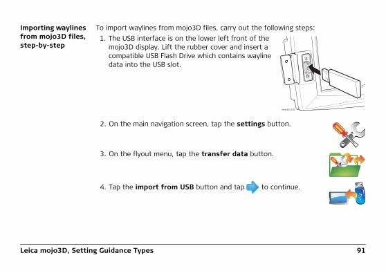
Importing waylines from mojo3D files, step-by-step
To import waylines from mojo3D files, carry out the following steps:1. The USB interface is on the lower left front of the
mojo3D display. Lift the rubber cover and insert a compatible USB Flash Drive which contains wayline data into the USB slot.
2. On the main navigation screen, tap the settings button.
3. On the flyout menu, tap the transfer data button.
4. Tap the import from USB button and tap to continue.
mojo3D_010

92Leica mojo3D, Setting Guidance Types
Importing waylines from Google Earth or Shapefile files, step-by-step
Google Earth and Shapefile files for waylines that have been exported from a mojo3D can be imported by mojo3Ds without information loss.
Before any files can be imported from the USB memory key, all files to import data from must be in the root (or base) folder of the USB memory key. If your third party application has created a folder structure, you need
If a mojoRTK is attached, waylines can be transferred from the mojoRTK to the mojo3D by tapping the button shown.
5. Tap the Guidance button and tap to continue.
If there is no wayline data on the USB Flash Drive the guid-ance button will not be displayed.
6. To select the waylines to be imported tap the wayline name to select or deselect it. All waylines can be selected by tapping the Select All button.
If there are waylines with the same name already on the mojo3D a screen will be displayed to allow the conflicting waylines to be renamed.
• Select automatic to have the mojo3D automatically create new names.OR• Select manual to allow each line to manually renamed.
7. Tap to return to the main navigation screen.

Leica mojo3D, Setting Guidance Types 93
to copy the files to be imported into the root folder of the USB memory key.
The mojo3D will not import Google Earth (kml/kmz) files from other sources as the format from third party applications and the mojo3D internal file format can vary significantly.
The mojo3D will import waylines from Shapefile files that are generated by third party applications providing the shape type is a polyline (sometimes just called a line) as defined in the Shapefile standard, HOWEVER, these waylines are only imported as replay waylines (see "4.7.7 Replay Guid-ance").
To import waylines from Google Earth or Shapefile files, carry out the following steps:1. The USB interface is on the lower left front of the
mojo3D display. Lift the rubber cover and insert a compatible USB Flash Drive that contains the wayline data into the USB slot.
mojo3D_010

94Leica mojo3D, Setting Guidance Types
2. On the main navigation screen, tap the guidance button.
3. On the flyout menu, tap the wayline management button.The Wayline Management screen appears.
4. Tap the import from USB button.(Note that the arrow goes from the USB memory key to the Google Earth icon - not the other way round.)
If there are no Google Earth or Shapefile files on the USB memory key to import, the button is disabled. You may have the wrong file formats on the USB memory key or you may not have the files in the root folder of the USB memory key.
The Select file type screen, shown below, appears.

Leica mojo3D, Setting Guidance Types 95
5. To import Google Earth files, tap the KML button.To import Shapefile files, tap the SHP button.
If there are no Google Earth files in the root directory of the USB memory key, the KML button is disabled. Similarly, if there are no Shapefile files in the root directory of the USB memory key, the SHP button is disabled.
The Select the items to import screen appears.6. Select the waylines to import by tapping their names. You can
select one wayline, many waylines, or all waylines by tapping the Select all button.

96Leica mojo3D, Setting Guidance Types
7. Tap the button.
If there are waylines with the same name already on the mojo3D, the Renaming required screen appears to allow the conflicting waylines to be renamed.
• To have the mojo3D automatically create new names, select Automatic. The mojo3D adds a number to the imported waylines’ names so you can identify the imported waylines.
OR• To manually rename the imported waylines, select Manual.
The Import Summary screen appears indicating the progress and success of the import.
8. To return to the wayline management screen, tap the button.The newly imported waylines now appear in the wayline manage-ment screen and are available for loading.
9. To return to the main navigation screen, tap the button.

Leica mojo3D, Setting Guidance Types 97
4.7.7 Replay Guidance
Overview Replay guidance allows a treatment to be loaded as a guidance pattern. Loading a treatment as a guidance pattern allows you to follow the path of a previous treat-ment but with the treatment cleared so that you can treat it again. The treatment file for the field must be kept as if it is deleted, the replay wayline file will also be deleted.
Be aware that the vehicle setup, implement width and implement offset need to be the same as when the treatment was originally created or else underlap and overlap will occur on the replay treatments.
Loading a treat-ment as a guidance pattern, step-by-step
To load a treatment as a guidance pattern, carry out the following steps:1. On the main navigation screen, tap the guidance button.
2. On the flyout menu, tap the wayline management button.The Wayline Management screen appears, with all of the saved waylines and saved treatments listed.
3. Select the treatment to load as a guidance pattern from the list by tapping its name.

98Leica mojo3D, Setting Guidance Types
4. To proceed with loading the treatment, tap the button.
You are returned to the main navigation screen and the path of the selected treatment displays on the screen.OR
To abandon loading the treatment, tap the button.
You are returned to the main navigation screen.5. Drive to the start of the wayline and engage auto-steer. The auto-
steer will follow the loaded treatment’s path.
Caution should be taken on the first lap or near obstacles in fields, as any GPS drift with time will result in the replay waylines shifting.
Leica mojo3D, Setting Guidance Types 99
4.8 Field Offset
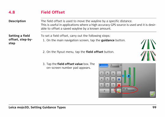
Description The field offset is used to move the wayline by a specific distance.This is useful in applications where a high accuracy GPS source is used and it is desir-able to offset a saved wayline by a known amount.
Setting a field offset, step-by-step
To set a field offset, carry out the following steps:1. On the main navigation screen, tap the guidance button.
2. On the flyout menu, tap the field offset button.
3. Tap the field offset value box. The on–screen number pad appears.

100Leica mojo3D, Setting Guidance Types
4. Use the on–screen number pad to enter a value for the field offset. Tap on the number pad when finished.
5. Tap to return to the main navigation screen.
Leica mojo3D, Setting Guidance Types 101
4.9 Nudge
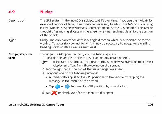
Description The GPS system in the mojo3D is subject to drift over time. If you use the mojo3D for extended periods of time, then it may be necessary to adjust the GPS position using nudge. Nudge uses the wayline as a reference to adjust the GPS position. This can be thought of as moving all data on the screen (waylines and map data) to the position of the vehicle.
Nudge can only correct for drift in a single direction which is perpendicular to the wayline. To accurately correct for drift it may be necessary to nudge on a wayline heading north/south as well as east/west.
Nudge, step-by-step
To nudge the GPS position, carry out the following steps:1. Position the vehicle on the tracks of an already driven wayline.
If the GPS position has drifted since this wayline was driven the mojo3D will display an offset from the wayline on the screen.
2. Tap the light bar at the top of the main navigation screen.3. Carry out one of the following actions:
• Automatically adjust to the GPS positions to the vehicle by tapping the message in the centre of the screen.
• Tap or to move the GPS position by a small step.
4. Tap or simply wait for the menu to disappear.

102Leica mojo3D, Auto-Steer
5 Auto-Steer5.1 Engage Auto-Steer
Auto-steer status The auto-steer button on the main navigation screen is used to engage and disen-gage auto-steer. The colour of this button also indicates the current status of the auto-steer.• Red: Roading is active and auto-steer can not be engaged until
roading is turned off.
• Orange: Roading is turned off, but the conditions for auto-steer toengage have not been met and auto-steer can not be engaged.Stationary engage is not armed.
• Yellow: Roading is turned off and auto-steer is ready, but notcurrently engaged. If the steering button is tapped the system willauto-steer immediately because all engage criteria are currentlysatisfied.
• Green with Pause: Auto-steer is armed but not active because thevehicle is not moving or the engage criteria are not satisfied.
• Green: Auto-steer is engaged and the vehicle is being automati-cally steered.

Leica mojo3D, Auto-Steer 103
Turn Roading off The Roading feature is a safety tool that is designed to prevent accidental engage-ment of automatic guiding when automatic guiding should not be engaged: for example, when a vehicle is on a public road, or when working around obstacles.
Turn Roading on To enable roading, carry out the following steps:
1. To turn roading off, tap the auto-steer button when it is red.
2. Tap to confirm roading is to be turned off.
1. On the main navigation screen, tap the steering settings button.
2. On the flyout menu, tap the roading button.
3. Roading will be enabled and the auto-steer button will turn red.

104Leica mojo3D, Auto-Steer
Preconditions to engage auto-steer
The conditions required for auto-steer to engage will depend on the steer kit being used. The following is a typical example of the conditions required to be met before automatic steering can occur:• Auto-steer correctly connected and configured• Roading off• Wayline set• Distance to wayline less than 6 m (20 ft)• Heading within 45 degrees of wayline• Travelling faster than 1 km/h (0.6 mph)• Not travelling faster than 30 km/h (18 mph)
Engage auto-steer
2. The auto-steer button will turn green to indicate auto-steer is engaged and thevehicle is being automatically steered.
Other methods to engage the steering will be available and this method will depend on the steer kit used.
1. On the main navigation screen, tap the auto-steer button when it is yellow.
Leica mojo3D, Auto-Steer 105
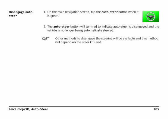
Disengage auto-steer
2. The auto-steer button will turn red to indicate auto-steer is disengaged and thevehicle is no longer being automatically steered.
Other methods to disengage the steering will be available and this method will depend on the steer kit used.
1. On the main navigation screen, tap the auto-steer button when it is green.

106Leica mojo3D, Auto-Steer
5.2 Tuning Auto-Steer Performance
General informa-tion
The tuning of the mojo3D is pre-loaded based on your selected vehicle/steering kit type and should be a reasonable starting point for tuning refinement. To refine the tuning of the system, there are four parameters:• Sensitivity• Aggressiveness• Overshoot• Speed Adjust
For optimal performance, the system tuning must be refined for your steering kit/vehicle.
5.2.1 Tuning Procedure
Tuning the mojo3D steering, step-by-step
To adjust the tuning settings for the mojo3D steering, carry out the following steps:1. On the main navigation screen, tap the auto-steer settings
button.

Leica mojo3D, Auto-Steer 107
2. On the flyout menu, tap the tuning button. The tuning wizard screen, shown below, appears.• All four tuning settings can be adjusted by selecting the relevant
button on the left side of the screen.• Each setting is specified by a nominal scale from 50 to 150.• The value of the setting is adjusted by moving an on-screen
slider.• The auto-steer performance is shown in the panel on the right
hand side of the screen.

108Leica mojo3D, Auto-Steer
Saving tuning data
• Tap to save all changes made to the settings, and return to the main naviga-tion screen.
• Tap to return to the main navigation screen without saving any changes madeto any of the tuning parameters.
This will discard all changes made to all tuning parameters, not just the changes made to the current parameter.

Leica mojo3D, Auto-Steer 109
5.2.2 Sensitivity
Setting the sensi-tivity
The sensitivity will control the rate that the vehicle turns and how sensitive it is when it is on the line. Sensitivity should be the only parameter that you need to adjust to adapt the control performance to the current working conditions after the tuning refinement is done.
2. Adjust the slider to vary the sensitivity, by using the and .
Explanation • The sensitivity can be set between 50% and 150%. The standard setting is 100%.• In general, higher sensitivity is for slower travelling speed, lower sensitivity for
faster speed.
1. On the tuning screen, tap the sensitivity button.
• Different sensitivity settings and theirapproach to the working line:
150%
100% 50%
mojoRTK_011

110Leica mojo3D, Auto-Steer
5.2.3 Aggressiveness
Setting the aggres-siveness
The aggressiveness will control the rate that the vehicle attacks the line and how well it holds the line.
2. Adjust the slider to vary the aggressiveness, by using the and .
Explanation • The aggressiveness can be set between 50% and 150%. The standard setting is100%.
1. On the tuning screen, tap the aggressiveness button.
• Different aggressiveness settings andtheir approach to the working line: 150%
100%
50%
mojoRTK_012

Leica mojo3D, Auto-Steer 111
5.2.4 Overshoot
Setting the over-shoot
The overshoot value will control the rate at which the vehicle will drive at the line and the rate that the vehicle will round off as it approaches the line. A low value will cause the vehicle to hold off the line longer while a high value will cause the vehicle to converge quickly and possibly drive past the line.
2. Adjust the slider to vary the overshoot, by using the and .
Explanation • The overshoot can be set between 50% and 150%. The standard setting is 100%.
1. On the tuning screen, tap the overshoot button.
• Different overshoot settings and theirapproach to the working line:
150%100%
50%
mojoRTK_013

112Leica mojo3D, Auto-Steer
5.2.5 Speed Adjust
Setting the speed adjust
The speed adjust should be used to fine tune the performance of the control system for higher speeds than the tuning speed of 5 km/h (3 mph). Typically, the vehicle can steer side to side at higher speeds, and this can be resolved by reducing the speed adjust. If the vehicle does not hold the line well at the desired speed, then increase the speed adjust.
2. Adjust the slider to vary the speed adjust, by using the left and right arrows.
• The speed adjust can be set between 50% and 150%. The standard value is100%.
• The speed adjust has no effect at or below 5 km/h (3 mph).
1. On the tuning screen, tap the speed adjust button.

Leica mojo3D, Auto-Steer 113
5.2.6 Tuning Tips
General tuning tips When dealing with the tuning, each parameter must be treated separately, even though they may have interactions between them.When tuning for:• turning rate and twitch on the line, use Sensitivity.• line holding, oscillations, and line approach speed, use Aggressiveness.• amount of overshoot or undershoot, use Overshoot.• variation over speed, use Speed Adjust.
Get these parameters right at 5 km/h (3 mph), and then tune for higher speeds using only the Speed Adjust.
In-depth tuning tips
Symptom Resolution
Vehicle is too slow to approach the line. Increase the Aggressiveness.
Vehicle is too fast to approach the line or the vehicle oscillates.
Decrease the Aggressiveness.
Vehicle straightens up before it gets to the line. Increase the Overshoot.
Vehicle drives past the line then comes back onto to the line.
Decrease the Overshoot.

114Leica mojo3D, Auto-Steer
Auto steer tuning tips, using Ultimate Curve Guidance
When using auto steer to follow Ultimate Curve guidance the tuning parameters may need to be refined. For best results:1. Tune auto steer following an AB Parallel line until satisfactory performance is
obtained.2. Refine the auto steer tuning by following a section of Ultimate Curve guidance.
• Record a line of coverage with gentle curves.• Turn coverage recording off.• Start Ultimate Curve and follow the line back and forth.
Vehicle turns very slowly to drive toward the line.
Increase the Sensitivity.
Vehicle turns very aggressively to drive toward the line and twitches when on the line.
Reduce the Sensitivity.
Vehicle oscillates only at higher speeds. Reduce the Speed Adjust.
Vehicle does not hold the line only at higher speeds.
Increase the Speed Adjust.
Symptom Resolution

Leica mojo3D, Auto-Steer 115
5.2.7 Swap Left and Right Steering Control
Overview This feature allows the service technician who is installing either a SteerDirect SRK or SteerDirect Hydraulic steerkit, to swap the left and right steering controls in situa-tions where after installation, the steering is pulsing or steering in the wrong direc-tion.
Swapping left and right steering control, step-by-step
To swap left and right steering control, carry out the following steps:1. On the main navigation screen, tap the auto-steer settings
button.
2. On the flyout menu, tap the steer settings button.The Valves Reversed screen appears.

116Leica mojo3D, Auto-Steer
3. Select the option required, either Normal or Reversed, by tappingthe appropriate button.
4. To save the selection, tap the button.
The saving screen appears showing the progress of the operation.
5. To return to the main navigation screen, tap the button.

Leica mojo3D, Auto-Steer 117
5.3 Stationary Engage and Reverse Steering
Overview The mojo3D supports stationary engage which allows the auto-steer system to be engaged before the vehicle moves. This allows the operator to concentrate on other tasks when the vehicle begins to move. Stationary engage also allows the vehicle to stop for a moment and then take off again without the operator having to manually re-engage the auto-steer system.
Reverse steering allows the operator to engage auto-steer while in reverse. Reverse steering is supported by some mojoXact steering platforms and vehicles.
Reverse steering is only permitted on straight wayline types, that is, AB Parallel Guidance and A+ Heading Guidance.
Stationary engage will automatically disengage if the vehicle has not moved for a configured amount of time. By default this amount of time is 15 seconds, but it can be configured to a value between 1 and 30 seconds.
Enabling reverse steering requires stationary engage to be enabled. This allows the operator to auto-steer while driving forwards, then stop, then drive in reverse, and the vehicle will continue to auto-steer without the operator having to manually re-engage auto-steer. The operator can then stop, go forward again and the auto-steer is still engaged. This can be

118Leica mojo3D, Auto-Steer
repeated a number of times without the operator needing to re-engage the auto-steer.
Enabling Stationary Engage and Reverse Steering, step-by-step
To enable stationary engage and reverse steering, carry out the following steps:1. On the main navigation screen, tap the settings button.
2. On the flyout menu, tap the attached device selection button.The Attached Device Selection screen appears.
3. On the Attached Device Selection screen, tap the button thatdescribes your setup.
4. Progress through the wizard by tapping the button until youget to the Enable Stationary Engage and Reverse Steering screenshown below.
The Enable Stationary Engage and Reverse Steering screen only appears if the device selected in step 3 supports stationary engage.

Leica mojo3D, Auto-Steer 119
If your steer kit or vehicle type does not support reverse steering then this optionwill not be visible.
5. To enable Stationary Engage and Reverse Steering, tap the appropriate greyboxes. The grey boxes become green indicating that these features are enabled.
To disable a feature tap its green box, and it becomes grey indicating that thefeature is now disabled.
If Reverse Steering is enabled, then Stationary Engage is automatically enabled as Reverse Steering requires Stationary Engage to be enabled. Conversely, if Stationary Engage is disabled then Reverse Steering is automatically disabled.
120Leica mojo3D, Auto-Steer
Setting the stationary engage time limit, step-by-step
At the Stationary Engage and Reverse Steering screen, you can set the Stationary Engage Time Limit to change how long the stationary engage system will stay engaged when the vehicle is not moving. The default time limit is 15 seconds but it can be set anywhere from 1 to 30 seconds.
Using stationary engage, step-by-step
Once Stationary Engage is enabled, auto-steer can be armed before the vehicle starts moving. To use stationary engage, carry out the following steps:
1. Ensure that roading is turned off (see "Turn Roading off" in "5.1 Engage Auto-Steer").
2. Ensure that a wayline is set or loaded to auto-steer along (see "4 Setting Guid-ance Types").
3. While the vehicle is stationary, tap the button.
The auto-steer button goes green with a pause symbol, signifying that auto-steeris armed, but not engaged.
4. Start moving the vehicle.
1. On the Stationary Engage and Reverse Steering screen, tap in the Stationary Engage Time Limit field and using the keypad that displays enter the new value.
2. Tap the button to proceed through the wizard to return to the main naviga-tion screen.

Leica mojo3D, Auto-Steer 121
The auto-steer system will automatically engage if the vehicle is close enough tothe wayline and is not attacking the line too steeply. Otherwise the auto-steersystem waits until these criteria are met before engaging.
If the vehicle does not move before the stationary engage time limit or the auto-steer engage criteria are not met before the time limit, stationary engage will disarm.
Using reverse engage, step-by-step
Reverse steering allows the operator to drive the vehicle forward and then in reverse and forward again without having to manually engage the auto-steering. Reverse steering requires stationary engage to be enabled. Without stationary engage enabled, the auto-steer system will disengage as the vehicle slows down between forward motion and reverse.
To use reverse engage carry out the following steps:1. Ensure that the reverse engage criteria below are met:
• the vehicle must be less than 1 (one) metre from the line.• the vehicle must have an attack angle with the line of less than 20 degrees.• the vehicle must be travelling at less than 6mph (10kph).• stationary engage must be enabled.• reverse steering must be enabled.
2. Engage auto-steer while driving in reverse.

122Leica mojo3D, Auto-Steer
OR
If auto-steer is engaged with the vehicle driving forwards, and the vehicle is onan AB or A+ heading wayline, and stationary engage is enabled, then reverseengage can be used by driving in reverse, providing the time between theforwards and reverse motion is shorter than the stationary engage time limit.
The vehicle can be driven between forward and reverse as many times as needed, and the auto-steer system will remain engaged as long as the vehicle is not stopped for longer than the stationary engage time limit.

Leica mojo3D, Auto-Steer 123
5.4 Testing Auto-Steer
Testing the auto-steer function, step-by-step
To perform a test on the auto-steer function, carry out the following steps:1. On the main navigation screen, tap the auto-steer settings
button.
2. On the flyout menu, tap the auto-steer test button.The Configure Steering Kit screen, shown below, appears.

124Leica mojo3D, Auto-Steer
If the mojo3D system thinks that the steering controller is not configured, the Configure Steering Kit screen appears with only the Start button visible, giving the operator the only option to write the configuration to the steering controller.
If the mojo3D system thinks that the steering controller is configured, then the Configure Steering Kit screen appears with the Skip button selected. The Skip operation leaves the steering controller’s configuration untouched. If the oper-ator believes that the configuration has changed and needs to be written to the steering controller, then at this screen they can select Send Configuration. Caution must be exercised before tapping the Start button, to ensure that the steering controller does not contain any configuration that is needed, as the Send Configuration operation will overwrite any existing configuration in the steering controller with factory default settings.
3. If you are certain that the steering controller needs to have configuration writtento it, then select the Send Configuration button and then tap the Start button.
If you are unsure about writing configuration to the steering controller, or you know that the steering controller is configured, select the Skip button.
4. Tap to continue
The steering kit information screen appears.

Leica mojo3D, Auto-Steer 125
5. Check that the steering kit is active. If the kit is not active, resolve
the issue, and then tap to continue.
The Steering Test screen appears.6. Check that the manual steering of the vehicle is safe and satisfac-
tory. Tap the OK button.7. Stop the vehicle and centre the wheels. Tap the OK button.8. Tap the auto-steer engage button to engage the auto-steer.
Auto-steer can be turned off at any time, by tapping the on-screen engage button or by manually moving the steering wheel.
9. Tap the turn left button, and check that the steering wheel turns tothe left.
10. Tap the centre button, and check that the steering wheel turns tothe centred position. Note that not all steer kits offer this function-ality.
11. Tap the turn right button, and check that the steering wheel turnsto the right.

126Leica mojo3D, Auto-Steer
12. After completing the steering test, disengage the auto-steer bytapping the auto-steer is engaged button.
13. Tap to return to the main navigation screen.

Leica mojo3D, Auto-Steer 127
128Leica mojo3D, Treatments
6 TreatmentsGeneral informa-tion
• Field treatments record the coverage activity that the user initiates by tapping on the master record status button.
• Coverage data is added in real time to the current field treatments record.• There is always a field treatment active.
The mojo3D supports:
• Starting a new treatment• Loading a stored treatment• Changing a treatment’s name• Creating a pdf report of a treatment• Deleting a treatment• Exporting treatment data to a USB memory key• Importing treatment data from a USB memory key

Leica mojo3D, Treatments 129
6.1 Starting a New Treatment
Starting a new treatment, step-by-step
To start a new treatment, carry out the following steps:
A previously saved wayline or guidance pattern can be loaded without turning the treatment off. This allows a wayline to be used for the treatment application.
1. On the main navigation screen, tap the mapping button.
2. On the flyout menu, tap the new treatment button.
3. On the dialog box that appears:
• tap to start a new treatment.
An on-screen keyboard appears. Enter a name for the treatment, and tap to return to the main navigation screen
OR
• tap to continue with the current treatment and return to the main navi-gation screen.

130Leica mojo3D, Treatments
6.2 Load a Stored Treatment
Load a stored treatment, step-by-step
To load a stored treatment, carry out the following steps:
3. Tap and to scroll though the list of treatments. Tap the treatment name to select it.
4. Tap to load the treatment and return to the main navigation screen.
1. On the main navigation screen, tap the mapping button.
2. On the flyout menu, tap the management button.

Leica mojo3D, Treatments 131
6.3 Changing a Treatment Name
Changing a treat-ment name, step-by-step
To change the name of an existing treatment, carry out the following steps:1. On the main navigation screen, tap the mapping button.
2. On the flyout menu, tap the management button.
3. Tap and to scroll though the list of treatments. Tap the treatment name to select it.
4. Tap the edit button.
5. Use the on-screen keyboard to change the name of the treatment, and then
tap .
6. Tap to return to the main navigation screen.

132Leica mojo3D, Treatments
6.4 Creating a PDF Report of a Treatment
General informa-tion
A PDF report of a treatment can be created directly on the mojo3D and exported to a USB Flash Drive. The report contains an image of the coverage map, the treatment’s name, area covered, start date and time, and end date and time.
A USB Flash Drive must be inserted into the mojo3D for this action to be available.
Creating a PDF report, step-by-step
To create a PDF report on a particular treatment, carry out the following steps:1. On the main navigation screen, tap the mapping button.
2. On the flyout menu, tap the management button.
3. Tap and to scroll though the list of treatments. Tap the treatment name to select it.
4. Tap the report button.
5. When the report is created a dialog box appears. Tap to close the dialog.

Leica mojo3D, Treatments 133
6. To load the selected treatment, tap the button. You are returned to the main navigation screen.OR
To leave the current treatment loaded, tap the button. You are returned to the main navigation screen.

134Leica mojo3D, Treatments
6.5 Deleting a Treatment
Deleting a treat-ment, step-by-step
A treatment may be deleted however care must be taken as if the treatment is used as a guidance pattern for replay guidance (see "4.7.7 Replay Guidance") and the treatment is deleted, the replay wayline file will also be deleted.
To delete a treatment, carry out the following steps:1. On the main navigation screen, tap the mapping button.
2. On the flyout menu, tap the management button.
3. Tap and to scroll though the list of treatments. Tap the treatment name to select it.
4. Tap the delete button.
5. On the dialog box that appears:
• tap to continue with the deletion.

Leica mojo3D, Treatments 135
OR
• tap to abandon the deletion.
6. To load the selected treatment, tap the button. You are returned to the main navigation screen.OR
To leave the current treatment loaded, tap the button. You are returned to the main navigation screen.

136Leica mojo3D, Treatments
6.6 Exporting Treatment Data
General informa-tion
Treatment data is exported in the following formats:• mojo3D files.• Google Earth kmz and kml files - contain the treatment map/coverage, any
boundary that may be associated with the treatment and a Replay Wayline which is the path used to create the treatment.
• tif files - these are GeoTIFF files that are images that can be used as an overlay in other mapping applications. These files can be opened by: Farm Works, SST Summit, Greenstar Apex and AgLeader SMS.
• tfw files - these are referencing files that are used by third party applications to position the GeoTIFF files correctly in the application.
The export of these file formats allows the user to produce and manage visually oriented work records.
Refer to "Appendix B Formatting USB Flash Drives" for important informa-tion about using USB drives with the mojo3D products.
Do not turn off the mojo3D, or remove the USB Flash Drive, while the treat-ment data export is under way.
You can export the mojo3D files or the Google Earth and GeoTIFF files.

Leica mojo3D, Treatments 137
Exporting the mojo3D data for treatments, step-by-step
To export data for all treatments stored in the mojo3D in mojo3D file format, carry out the following steps:1. The USB interface is on the lower left front of the
mojo3D display. Lift the rubber cover and insert a compatible USB Flash Drive into the USB slot.
2. On the main navigation screen, tap the settings button.
3. On the flyout menu, tap the transfer data button.
4. Tap the export to USB button and tap to continue.
mojo3D_010

138Leica mojo3D, Treatments
5. Tap the Field button and tap to continue.
If there is already data on the USB Flash Drive there will be a message to confirm overwriting the data.
6. On the dialog box that appears:
• tap to overwrite the data on the USB Flash Drive.
The Export Summary screen appears, showing the progress and success of the export process.OR
• tap to cancel the copy operation.
7. Tap to return to the main navigation screen.

Leica mojo3D, Treatments 139
Exporting Google Earth and GeoTIFF data for a selected treatment, step-by-step
To export Google Earth and GeoTIFF data for a selected treatment, carry out the following steps:1. The USB interface is on the lower left front of the
mojo3D display. Lift the rubber cover and insert a compatible USB Flash Drive into the USB slot.
2. On the main navigation screen, tap the mapping button.
3. On the flyout menu, tap the management button.The Field Management screen appears.
4. Tap and to scroll though the list of treatments. To select the treatment to export, tap the treatment name.
mojo3D_010

140Leica mojo3D, Treatments
5. To export the selected treatment’s data, tap the export to USB button. (Note that the export button has the arrow pointing to the USB memory key.)
Depending on the size of the treatment map, the export operation may take a minute or more.
If files already exist on the USB memory key with the same names as the treatment files being exported, a dialog displays a message to confirm the overwriting of the data.
6. To overwrite the existing data, tap the button.
To cancel the export operation, tap the button.
When the export of the treatment data is complete, a message similar to the one below appears.

Leica mojo3D, Treatments 141
7. To close the message box and return to the field management screen, tap the
button.
8. To load the selected treatment, tap the button. You are returned to the main navigation screen.OR
To leave the current treatment loaded, tap the button. You are returned to the main navigation screen.

142Leica mojo3D, Treatments
6.7 Importing Treatment Data
Importing treat-ment data, step-by-step
Refer to "Appendix B Formatting USB Flash Drives" for important informa-tion about using USB drives with the mojo3D products.
Do not turn off the mojo3D, or remove the USB Flash Drive, while the treat-ment data import is under way.
To import treatment data, carry out the following steps:1. The USB interface is on the lower left front of the
mojo3D display. Lift the rubber cover and insert a compatible USB Flash Drive into the USB slot.
2. On the main navigation screen, tap the settings button.
mojo3D_010

Leica mojo3D, Treatments 143
3. On the flyout menu, tap the transfer data button.
4. Tap the import from USB button and tap to continue.
The Select the data to transfer screen appears.
5. Tap the Field button and tap to continue.
If there is no field data on the USB Flash Drive the button will not be displayed.
The Select the items to import screen appears.
Select the treatments by tapping their buttons. You can select one treatment, many treatments or all treatments by tapping the Select All button.

144Leica mojo3D, Treatments
6. Tap the button.
If there are treatments with the same name already on the mojo3D, the Renaming required screen displays to allow the conflicting treatments to be renamed.
• To have the mojo3D automatically create new names, select Automatic. The mojo3D adds a number to the imported treatments’ names so you can identify the imported treatments.
OR• To manually rename the imported treatments, select Manual.
7. To proceed with the import, tap the button.
If you chose Automatic renaming, the Import Summary screen displays.If you chose Manual renaming, the Items below must be renamed screen displays.• Tap a vehicle configuration to select it.• Tap the Rename button.• Use the on-screen keyboard to enter a new name for the configuration.• Repeat the above three steps for each configuration in the list.
• To proceed with the import, tap the button.
The Import Summary screen displays showing the progress and success of the import.

Leica mojo3D, Treatments 145
8. To return to the main navigation screen tap the button.
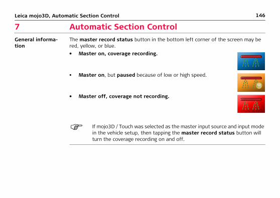
146Leica mojo3D, Automatic Section Control
7 Automatic Section ControlGeneral informa-tion
The master record status button in the bottom left corner of the screen may be red, yellow, or blue.
If mojo3D / Touch was selected as the master input source and input mode in the vehicle setup, then tapping the master record status button will turn the coverage recording on and off.
• Master on, coverage recording.
• Master on, but paused because of low or high speed.
• Master off, coverage not recording.

Leica mojo3D, Automatic Section Control 147
7.1 Section Control Latency
Definition Latency is the time interval from when the section switch is toggled from ON to OFF or from OFF to ON, to when the application physically stops or starts.
Simple measure-ment
The quickest way to estimate the latency is to use a stop watch to time the delay between turning a section ON and the application physically starting. This may be a very small value - a few tenths of a second - and hard to measure accurately.Latency can be measured more accurately by measuring the distance travelled at a given speed.

148Leica mojo3D, Automatic Section Control
7.1.1 Calibrating the Section Control Latency Value
For the purpose of this calibration exercise, if using a boom spray, the tank should contain only water.
Calibrating latency, step-by-step
To calibrate the section control latency value, carry out the following steps:1. Drive slowly in a straight line for
200 m (650 ft) with the master on. Half way along the run, mark on the ground where the end of the imple-ment passes with two pegs and a rope.
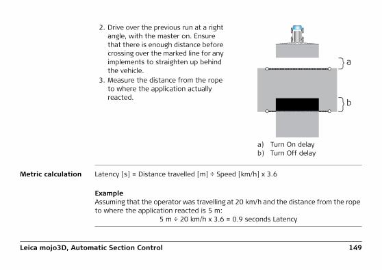
Leica mojo3D, Automatic Section Control 149
Metric calculation Latency [s] = Distance travelled [m] ÷ Speed [km/h] x 3.6
ExampleAssuming that the operator was travelling at 20 km/h and the distance from the rope to where the application reacted is 5 m:
5 m ÷ 20 km/h x 3.6 = 0.9 seconds Latency
2. Drive over the previous run at a right angle, with the master on. Ensure that there is enough distance before crossing over the marked line for any implements to straighten up behind the vehicle.
3. Measure the distance from the rope to where the application actually reacted.
a) Turn On delayb) Turn Off delay
a
b

150Leica mojo3D, Automatic Section Control
Imperial/US calcu-lation
Latency [s] = Distance travelled [ft] ÷ Speed [mph] x 0.68
ExampleAssuming that the operator was travelling at 12 mph and the distance from the rope to where the application reacted is 16 ft:
16 ft ÷ 12 mph x 0.68 = 0.9 seconds Latency
7.1.2 Troubleshooting Latency Problems
Latency problems Solutions to some problems are given in the following table:
Problem Solution
The section takes too long to turn OFF, and overlap results.
Increase the OFF latency value.

Leica mojo3D, Automatic Section Control 151
The section is turned OFF too early, and a missed area results.
Decrease the OFF latency value.
The section takes too long to turn ON, and a missed area results.
Increase the ON latency value.
Problem Solution

152Leica mojo3D, Automatic Section Control
The section turns ON too early, and an overlap results.
Decrease the ON latency value.
Problem Solution

Leica mojo3D, Automatic Section Control 153
7.2 Setting the Overlap Limit
Definition The overlap limit sets how sensitive the auto section control is to misses and over-laps. When the overlap limit is set to its default value of 100%, the section will turn on whenever any part of the sensed area has not been applied.
If the overlap limit is decreased, the system will not turn on the application when traversing a small missed area, such as a strip between two spray swaths.
100% 50% 25% 0%

154Leica mojo3D, Automatic Section Control
Setting the overlap limit, step-by-step
To set the overlap limit, carry out the following steps:1. On the main navigation screen, tap the settings button.
2. On the flyout menu, tap the Vehicle setup button.
3. Tap several times until the Section Control Setup screen is shown.
4. Tap the Overlap Limit value box.
5. Use the on–screen number pad to enter a value for the overlap limit. Tap on the number pad when finished.
6. Tap to return to the main navigation screen.

Leica mojo3D, Automatic Section Control 155
7.3 Setting the Low-Speed Shutoff
Description • Low-speed shutoff can be used to stop application automatically whenever the vehicle stops.
• Low-speed shutoff works by section, and so can be used to turn the slow–moving inside section off when the vehicle is travelling on a curved path.
Setting low-speed shutoff, step-by-step
To set the low-speed shutoff, carry out the following steps:1. On the main navigation screen, tap the settings button.
2. On the flyout menu, tap the Vehicle setup button.

156Leica mojo3D, Automatic Section Control
3. Tap several times until the Section Control Setup screen is shown.
4. Tap the Low Speed Shutoff value box.
5. Use the on–screen number pad to enter a value for the minimum speed. Tap on the number pad when finished.
6. Tap to return to the main guidance screen.

Leica mojo3D, Automatic Section Control 157
7.4 Section Override Control
Section override control, step-by-step
To override the automatic section control, carry out the following steps:1. With the master on and coverage being recorded, tap anywhere on the horizontal
section control bar at the bottom of the screen.2. Tap a section on the section
control override bar, or tap or
to select a section to override.
3. Tap Auto, On or Off to set the override state.• On: The section will apply coverage when the master record button is on
(blue), even when travelling over an area already covered.• Off: The section is turned off, and will not apply coverage.• Auto: Auto section control will operate as normal.
4. Or, change all the settings at once by tapping All Auto, All On, or All Off.
5. Tap to close the section override control.

158Leica mojo3D, Field Boundary
8 Field Boundary8.1 Create a New Field Boundary
Benefits Field boundaries can be recorded and saved in the mojo3D. This means more precise application can be performed with less wastage as the total field area is known along with the area remaining to be covered. Operators not familiar with a field can load a boundary created earlier to have the confidence to complete a field at night.
New field boundary, step-by-step
To create a new field boundary, carry out the following steps:1. On the main navigation screen, tap the mapping button.
2. On the flyout menu, tap the new boundary button.
• To record the boundary to the left of the implement tap .
• To record the boundary in line with the antenna tap .
• To record the boundary to the right of the implement tap .

Leica mojo3D, Field Boundary 159
The field boundary is automatically saved with the same name as the current treatment when it is closed.
3. Drive the perimeter of the field to record the boundary line.4. To close the field boundary take one of the following actions:
• Tap then to manually close the boundary.
• Drive close to the boundary start point and tap when it is displayed on the main navigation screen.
• Drive over the start point and the boundary will automatically close.

160Leica mojo3D, Field Boundary
8.2 Load a Stored Field Boundary
Load a stored field boundary, step-by-step
To load a stored field boundary, carry out the following steps:1. On the main navigation screen, tap the mapping button.
2. On the flyout menu, tap the boundary management button.
3. Tap or to scroll through the list of boundaries. Tap the boundary name to select it.
4. Tap to load the boundary.
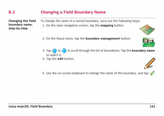
Leica mojo3D, Field Boundary 161
8.3 Changing a Field Boundary Name
Changing the field boundary name, step-by-step
To change the name of a stored boundary, carry out the following steps:1. On the main navigation screen, tap the mapping button.
2. On the flyout menu, tap the boundary management button.
3. Tap or to scroll through the list of boundaries. Tap the boundary name to select it.
4. Tap the edit button.
5. Use the on-screen keyboard to change the name of the boundary, and tap .

162Leica mojo3D, Field Boundary
8.4 Deleting a Field Boundary
Deleting a field boundary, step-by-step
To delete a stored field boundary, carry out the following steps:
5. On the dialog box that appears:
• tap to continue with the deletion.
OR
• tap to abandon the deletion.
Deleting a boundary will remove the boundary line from any associated treatments.
1. On the main navigation screen, tap the mapping button.
2. On the flyout menu, tap the boundary management button.
3. Tap or to scroll through the list of boundaries. Tap the boundary name to select it.
4. Tap the delete button.

Leica mojo3D, Field Boundary 163
8.5 Exporting Field Boundary Data
General informa-tion
Boundary data can be exported in the following formats:• mojo3D files.• Google Earth kml files.• Shapefile shp, dbf, prj and shx files - which can be opened by other third party
applications.
Refer to "Appendix B Formatting USB Flash Drives" for important informa-tion about using USB drives with the mojo3D products.
Do not turn off the mojo3D, or remove the USB Flash Drive, while the data export is under way.
You can export the mojo3D files or the Google Earth and Shapefile files.

164Leica mojo3D, Field Boundary
Exporting field boundary data, step-by-step
To export all field boundary data stored in the mojo3D in a mojo3D file format, carry out the following steps:1. The USB interface is on the lower left front of the
mojo3D display. Lift the rubber cover and insert a compatible USB Flash Drive into the USB slot.
2. On the main navigation screen, tap the settings button.
3. On the flyout menu, tap the transfer data button.
4. Tap the export to USB button and tap to continue.
mojo3D_010

Leica mojo3D, Field Boundary 165
6. On the dialog box that appears:
• tap to overwrite the data on the USB Flash Drive.
The Export Summary screen displays, showing the progress and success of the export process.OR
• tap to cancel the copy operation.
7. Tap to return to the main navigation screen.
5. Tap the boundary button and tap to continue.
If there is already data on the USB Flash Drive there will be a message to confirm overwriting the data.

166Leica mojo3D, Field Boundary
Exporting Google Earth and Shapefile data for a selected boundary, step-by-step
To export Google Earth and Shapefile data for a selected field boundary, carry out the following steps:1. The USB interface is on the lower left front of the
mojo3D display. Lift the rubber cover and insert a compatible USB Flash Drive into the USB slot.
2. On the main navigation screen, tap the mapping button.
3. On the flyout menu, tap the boundary management button.The Field Management screen displays.
4. Tap and to scroll though the list of field boundaries. To select the field boundary to export, tap the boundary name.
mojo3D_010

Leica mojo3D, Field Boundary 167
5. To export the selected boundary’s data, tap the export to USB button. (Note that the export button has the arrow pointing to the USB memory key.)
Depending on the size of the field boundary, the export oper-ation may take a minute or more.
If files already exist on the USB memory key with the same names as the boundary files being exported, a dialog displays a message to confirm the overwriting of the data.
6. To overwrite the existing data, tap the button.
To cancel the export operation, tap the button.
When the export of the field boundary data is complete, a message displays stating that the data has been saved.
7. To close the message box and return to the boundary management screen, tap
the button.

168Leica mojo3D, Field Boundary
8. To load the selected field boundary, tap the button. You are returned to the main navigation screen.OR
To leave the current boundary loaded, tap the button. You are returned to the main navigation screen.
Leica mojo3D, Field Boundary 169
8.6 Importing Field Boundary Data
General informa-tion
Field boundary data in the following formats can be imported into a mojo3D:• mojo3D files.• Google Earth kml files.• Shapefile .shp, .dbf, .prj and .shx files.
Refer to "Appendix B Formatting USB Flash Drives" for important informa-tion about using USB drives with the mojo3D products.
Do not turn off the mojo3D, or remove the USB Flash Drive, while the data import is under way.
You can import mojo3D files, Google Earth files or Shapefile files.

170Leica mojo3D, Field Boundary
Importing field boundary data from mojo3D files, step-by-step
To import field boundary data from mojo3D files, carry out the following steps:1. The USB interface is on the lower left front of the
mojo3D display. Lift the rubber cover and insert a compatible USB Flash Drive into the USB slot.
2. On the main navigation screen, tap the settings button.
3. On the flyout menu, tap the transfer data button.
4. Tap the import from USB button and tap to continue.
The Select the data to transfer screen displays.
mojo3D_010

Leica mojo3D, Field Boundary 171
6. To select the field boundaries to be imported tap the boundary name to select or deselect it. All field boundaries can be selected by tapping the Select all button.
7. Tap the button.
If there are field boundaries with the same name already on the mojo3D a screen will be displayed to allow the conflicting field boundaries to be renamed.
• Select automatic to have the mojo3D automatically create new names.OR• Select manual to allow each field boundary to be manually renamed.
8. To proceed with the import, tap the button.The Import Summary screen displays showing the progress and success of the import.
9. Tap to return to the main navigation screen.
5. Tap the boundary button and tap to continue.
If there is no field boundary data on the USB Flash Drive the boundary button will not be displayed.
The Select the items to import screen displays.

172Leica mojo3D, Field Boundary
Importing field boundary data from Google Earth or Shapefile files, step-by-step
Google Earth and Shapefile files for field boundaries that have been exported from a mojo3D can be imported by mojo3Ds. Some Shapefile files generated by third party applications can also be imported by mojo3Ds.
Google Earth boundary objects that are exported from a mojo3D, can be moved and restructured within Google Earth and then saved as a new Google Earth file. The new Google Earth file may contain one or more mojo3D objects, and the mojo3D can still import the objects contained in those files.
Before any files can be imported from the USB memory key, all files to import data from must be in the root (or base) folder of the USB memory key. If your third party application has created a folder structure, you need to copy the files to be imported into the root folder of the USB memory key.
The mojo3D will not import kml/kmz files from other sources as the format from other third party applications and the mojo3D internal file format can vary significantly.
The mojo3D will import field boundaries from Shapefile files that were generated by third party applications, provided the shape type is a polygon as defined in the Shapefile standard.

Leica mojo3D, Field Boundary 173
To import field boundary data from Google Earth or Shapefile files, carry out the following steps:1. The USB interface is on the lower left front of the
mojo3D display. Lift the rubber cover and insert a compatible USB Flash Drive into the USB slot.
2. On the main navigation screen, tap the treatment button.
3. On the flyout menu, tap the boundary management button.The Boundary management screen displays.
4. Tap the import from USB button.(Note that the arrow goes from the USB memory key to the Google Earth icon - not the other way round.)
mojo3D_010

174Leica mojo3D, Field Boundary
If there are no Google Earth or Shapefile files on the USB memory key to import, the button is disabled. You may have the wrong file formats on the USB memory key or you may not have the files in the root folder of the USB memory key.
The Select file type screen, shown below, displays.
5. To import Google Earth files, tap the KML button.To import Shapefile files, tap the SHP button.

Leica mojo3D, Field Boundary 175
If there are no Google Earth files in the root directory of the USB memory key, the KML button is disabled. Similarly, if there are no Shapefile files in the root directory of the USB memory key, the SHP button is disabled.
The Select the items to import screen displays.
6. Select the boundaries to import by tapping their buttons. You can select one boundary, many boundaries, or all boundaries by tapping the Select all button.
7. Tap the button.
If there are field boundaries with the same name already on the mojo3D, the Renaming required screen displays to allow the conflicting field bound-aries to be renamed.
• To have the mojo3D automatically create new names, select Automatic. The mojo3D adds a number to the imported boundaries’ names so you can identify the imported boundaries.
OR• To manually rename the imported boundaries, select Manual.
8. To proceed with the import, tap the button.The Import Summary screen displays indicating the progress and success of the import.

176Leica mojo3D, Field Boundary
9. To return to the Boundary management screen, tap the button.The newly imported boundaries now appear in the Boundary management screen and are available for loading.
10. To return to the main navigation screen, tap the button.
Leica mojo3D, Field Boundary 177
178Leica mojo3D, Vehicles and Implements
9 Vehicles and Implements
Overview The mojo3D supports:
• Saving vehicle and implement configurations• Loading previously saved vehicle and implement configurations• Renaming vehicle and implement configurations• Deleting vehicle and implement configurations• Exporting vehicle and implement configurations to a USB memory key• Importing vehicle and implement configurations from a USB memory key
The save, load, export and import features allow the transfer of vehicle settings from one mojo3D to another so that you can use any of your mojo3D devices on any vehicle that was originally configured on a different mojo3D.
The saving and loading features have been implemented on the assumption that only the mojo3D moves from vehicle to vehicle. If a vehicle has a mojoXact installed, it is assumed that the mojoXact stays with the vehicle. The mojoXact is designed to be fitted and calibrated and to then stay in the vehicle.
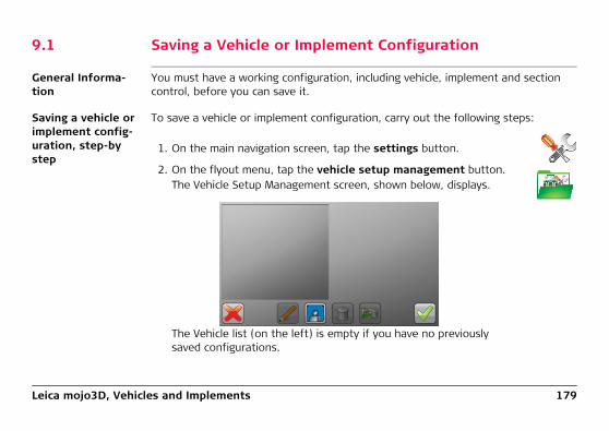
Leica mojo3D, Vehicles and Implements 179
9.1 Saving a Vehicle or Implement Configuration
General Informa-tion
You must have a working configuration, including vehicle, implement and section control, before you can save it.
Saving a vehicle or implement config-uration, step-by step
To save a vehicle or implement configuration, carry out the following steps:
1. On the main navigation screen, tap the settings button.
2. On the flyout menu, tap the vehicle setup management button.The Vehicle Setup Management screen, shown below, displays.
The Vehicle list (on the left) is empty if you have no previously saved configurations.

180Leica mojo3D, Vehicles and Implements
3. To save the current vehicle configuration, tap the button.
The saved configuration appears in the list on the left with a default name as shown below. The configuration can be renamed by following the steps in "9.3 Renaming a Vehicle or Implement Configuration".
4. To return to the main navigation screen, tap the button.

Leica mojo3D, Vehicles and Implements 181
9.2 Load a Vehicle or Implement Configuration
General Informa-tion
If there are vehicle or implement configurations saved on the mojo3D, then they can be reloaded so the user does not have to re-enter the details of the configuration.
It is up to the operator to confirm that the correct configuration is loaded and that the settings are correct. The system cannot detect if incorrect settings have been loaded.
Loading a vehicle or implement configuration, step-by-step
To load a vehicle or implement configuration, carry out the following steps:
1. On the main navigation screen, tap the settings button.

182Leica mojo3D, Vehicles and Implements
2. On the flyout menu, tap the vehicle setup management button.The Vehicle Setup Management screen, shown below, displays with the currently saved configurations listed on the left.
3. Tap the configuration to be loaded to select it.The right side of the screen displays some information about the selected config-uration so you can confirm you have selected the correct configuration.
4. To continue with the loading of the selected configuration tap the button.
The configuration is loaded and you are returned to the main navigation screen.OR
To cancel the loading operation, tap the button.
No changes are made to the configuration and you are returned to the main navi-gation screen.

Leica mojo3D, Vehicles and Implements 183
9.3 Renaming a Vehicle or Implement Configuration
General Informa-tion
Configurations are saved with default names, so it is good practice to rename a configuration with a meaningful name so it is easily identifiable.
The mojo3D allows multiple configurations to have the same name, however it is highly recommended that each configuration has a unique name.
Renaming a vehicle or implement configuration, step-by-step
To rename a vehicle or implement configuration, carry out the following steps:
1. On the main navigation screen, tap the settings button.

184Leica mojo3D, Vehicles and Implements
2. On the flyout menu, tap the vehicle setup management button.The Vehicle Setup Management screen, shown below, displays with the currently saved configurations listed on the left.
3. Select the configuration to be renamed by tapping it.
4. Tap the edit button.
5. Use the on-screen keyboard to change the name of the vehicle or implement configuration.

Leica mojo3D, Vehicles and Implements 185
6. Tap the button to save the configuration’s name.
The keyboard closes and the configuration’s new name appears in the list on the left.OR
Tap the to cancel the name change.
7. To return to the main navigation screen, tap the button.
This leaves the currently loaded configuration unchanged.
To load the configuration that is currently selected in the list, tap
the button.

186Leica mojo3D, Vehicles and Implements
9.4 Deleting Vehicle or Implement Configurations
General Informa-tion
Vehicle configurations that are incorrect or no longer required, can be deleted.
TAKE CARE...once a configuration is deleted it cannot be recovered or restored. If you accidentally delete a configuration you will need to manu-ally recreate it and save it again.
Deleting a vehicle or implement configuration, step-by-step
To delete a vehicle configuration, carry out the following steps:
1. On the main navigation screen, tap the settings button.

Leica mojo3D, Vehicles and Implements 187
2. On the flyout menu, tap the vehicle setup management button.The Vehicle Setup Management screen, shown below, displays with the currently saved configurations listed on the left.
3. Select the configuration to be deleted by tapping it.
4. Ensure that the currently selected configuration is the one that you want to delete.
5. To permanently delete the selected configuration, tap the delete button.A dialog box displays asking you to confirm that you want to proceed with the deletion.
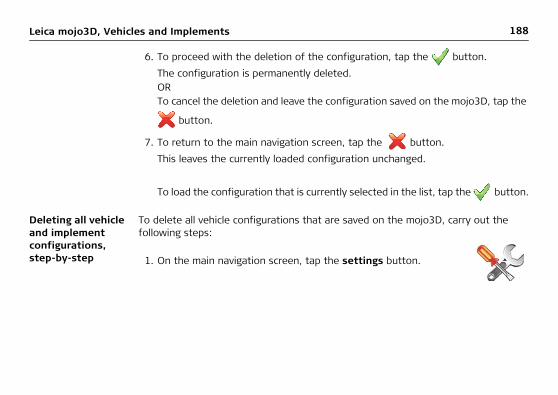
188Leica mojo3D, Vehicles and Implements
6. To proceed with the deletion of the configuration, tap the button.
The configuration is permanently deleted.ORTo cancel the deletion and leave the configuration saved on the mojo3D, tap the
button.
7. To return to the main navigation screen, tap the button.
This leaves the currently loaded configuration unchanged.
To load the configuration that is currently selected in the list, tap the button.
Deleting all vehicle and implement configurations, step-by-step
To delete all vehicle configurations that are saved on the mojo3D, carry out the following steps:
1. On the main navigation screen, tap the settings button.

Leica mojo3D, Vehicles and Implements 189
2. On the flyout menu, tap the vehicle setup management button.The Vehicle Setup Management screen, shown below, displays with the currently saved configurations listed on the left.
3. To permanently delete all vehicle configurations, tap the delete all button.A dialogue displays asking you to confirm that you want to proceed with the deletion of all vehicle configurations.

190Leica mojo3D, Vehicles and Implements
4. To proceed with the deletion of the configurations, tap the button.
The configurations are permanently deleted.ORTo cancel the deletion and leave the configurations saved on the mojo3D, tap the
button.
5. To return to the main navigation screen, tap the button.
This leaves the currently loaded configuration unchanged.
To load the configuration that is currently selected in the list (if there is one), tap
the button.

Leica mojo3D, Vehicles and Implements 191
9.5 Exporting Vehicle or Implement Configurations
Exporting vehicle or implement configurations, step-by-step
When you export vehicle configurations to a USB memory key, you will overwrite any vehicle configurations that may already be on the USB memory key.
Refer to "Appendix B Formatting USB Flash Drives" for important informa-tion about using USB memory keys with the mojo3D products.
Do not turn off the mojo3D, or remove the USB memory key, while the data export is under way.
To export vehicle or implement configurations, carry out the following steps:1. The USB interface is on the lower left front of the
mojo3D display. Lift the rubber cover and insert a compatible USB memory key into the USB slot.
mojo3D_010

192Leica mojo3D, Vehicles and Implements
2. On the main navigation screen, tap the settings button.
3. On the flyout menu, tap the transfer data button.The Select the operation to perform screen, shown below, displays.
4. Tap the export to USB button to select it.(Note that the arrow goes from the mojo3D to the USB memory key, not the other way round.)

Leica mojo3D, Vehicles and Implements 193
5. Tap the button.
The Select the data to transfer screen, shown below, displays.
6. To start the export of vehicle configurations tap the vehicle setup button to select it.
7. Tap the button.
If there is already exported vehicle configurations on the USB memory key, a message appears to confirm the overwriting of the existing data.

194Leica mojo3D, Vehicles and Implements
8. On the dialog box that appears:
• tap to overwrite the vehicle configurations on the USB memory key.
OR
• tap to abandon the export operation.
If you proceed with the export operation, the Export Summary screen, shown below, displays.
9. To return to the main navigation screen tap the button.

Leica mojo3D, Vehicles and Implements 195
9.6 Importing Vehicle and Implement Configurations
Importing vehicle and implement configurations, step-by-step
Before you can import vehicle or implement configurations, you need to have a USB memory key that contains vehicle or implement configurations that were previously exported from a mojo3D.
Refer to "Appendix B Formatting USB Flash Drives" for important informa-tion about using USB memory keys with the mojo3D products.
Do not turn off the mojo3D, or remove the USB memory key, while the data import is under way.
To import vehicle and implement configurations, carry out the following steps:1. The USB interface is on the lower left front of the
mojo3D display. Lift the rubber cover and insert a compatible USB memory key into the USB slot.
mojo3D_010
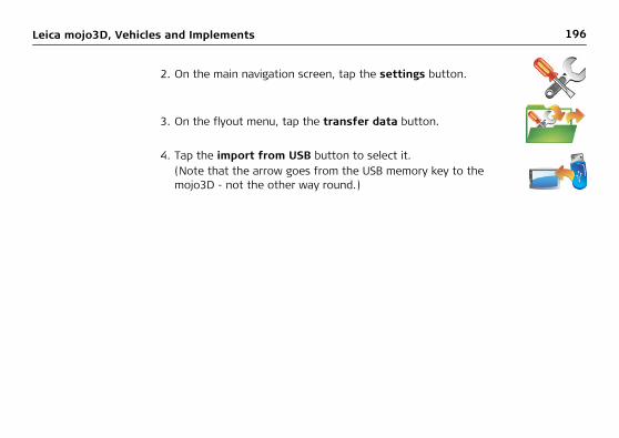
196Leica mojo3D, Vehicles and Implements
2. On the main navigation screen, tap the settings button.
3. On the flyout menu, tap the transfer data button.
4. Tap the import from USB button to select it.(Note that the arrow goes from the USB memory key to the mojo3D - not the other way round.)

Leica mojo3D, Vehicles and Implements 197
5. Tap the button.
The Select the data to transfer screen, shown below, displays.
6. To start the import of vehicle and implement configurations, tap the vehicle setup button to select it.
If there is no vehicle or implement configuration data on the USB memory key, then the vehicle setup button will not be visible.

198Leica mojo3D, Vehicles and Implements
8. Tap the button.
If there are vehicle configurations with the same name already on the mojo3D, the Renaming required screen, shown below, displays to allow the conflicting vehicle configurations to be renamed.
7. Tap the button.
The Select the items to import screen, shown below, displays.
Select the vehicle and implement configurations by tapping their buttons. You can select one vehicle configuration, many vehicle configurations or all configu-rations by tapping the Select All button.

Leica mojo3D, Vehicles and Implements 199
• To have the mojo3D automatically create new names, select Automatic. The mojo3D adds a number to the imported configurations’ names so you can identify the imported vehicle configurations.
OR• To manually rename the imported vehicle configurations, select Manual.
9. To proceed with the import, tap the button.
If you chose Automatic renaming, the Import Summary screen, shown below, displays.If you chose Manual renaming, the Items below must be renamed screen, shown below, displays.

200Leica mojo3D, Vehicles and Implements
• Tap a vehicle configuration to select it.• Tap the Rename button.• Use the on-screen keyboard to enter a new name for the configuration.• Repeat the above three steps for each configuration in the list.
• To proceed with the import, tap the button.
The Import Summary screen, shown below, displays.

Leica mojo3D, Vehicles and Implements 201
The Import Summary screen indicates the progress and success of the import.10. To complete the import wizard and return to the main navigation screen, tap the
button.

202Leica mojo3D, Correction Sources
10 Correction SourcesOverview The mojo3D can be configured to use one of following correction sources for position
data:• Network DGPS - utilises a network of base stations or single base stations to
provide differential GPS correction signals via the cell phone network. Network DGPS can be configured as a correction source for a standalone mojo3D.
• SBAS - Space Based Augmentation Systems, can be configured for standalone mojo3Ds located in regions that support SBAS.
• GL1DETM - can be configured as the only source of position data for a mojo3D, utilising the antenna/s installed on the vehicle, or as the backup for position data in the event that the connection to the configured correction source fails.
• Network RTK - utilises a network of permanent base stations operated by a network provider, and therefore there is no need for a local base station. Network RTK offers very quick convergence times compared to other correction sources available. The Network RTK base stations are survey quality and mounted in fixed positions, offering repeatability from year to year. To configure Network RTK as the correction source for a mojo3D, the mojo3D must be connected to a mojoXact/mojoXact Plus.
• RTK Base Station - utilises a local base station for position data for a mojo3D that is connected to a mojoXact/mojoXact Plus.
Each correction source and how to configure it is discussed in the sections below.

Leica mojo3D, Correction Sources 203
10.1 Network DGPS
Overview Standalone mojo3D systems (that is, those not connected to a mojoXact/mojoXact Plus) provide DGPS (Differential GPS) position type. Network DGPS utilises a network of base stations or single base stations to provide differential GPS correction signals via the cell phone network.
Benefit The Network DGPS option for the mojo3D provides an increase in accuracy over the standard product. This accuracy increase is most pronounced in the absolute position and not so much in the pass to pass. The absolute accuracy of the mojo3D with Network DGPS is reduced to 0.50 meters RMS, however this accuracy is impacted by the distance to the base station. Excellent performance improvements can be achieved with base stations in the order of 150km away.
Before a mojo3D can be configured to use Network DGPS, unlock codes are required for Network DGPS and a Network Data Plan. Contact your dealer to obtain the required redeeming vouchers.
Loading unlock codes onto the mojo3D
There are two ways that the unlock codes can be loaded onto the mojo3D:1. Connect the mojo3D to Virtual Wrench (see "12 Virtual Wrench™ Remote
Service").Once connected, the new codes are automatically loaded onto the mojo3D.
OR2. Enter the codes manually via the mojo3D, as described in "3.15 Feature Unlock".

204Leica mojo3D, Correction Sources
Once the codes are entered, confirm that the Network DGPS and the Network Data Plan are both unlocked by carrying out the following steps:1. At the main navigation screen, tap the settings button.
2. On the flyout menu, tap the Features Settings button.The Feature status screen appears.
3. Confirm that Network DGPS and Network Data Plan are unlocked.
Tap to return to the main navi-gation screen.

Leica mojo3D, Correction Sources 205
Enabling Network DGPS, step-by-step
The mojo3D must be configured as a standalone mojo3D and the Network DGPS and Network Data Plan features must be unlocked.To enable Network DGPS, carry out the following steps:1. At the main navigation screen, tap the settings button.
2. On the flyout menu tap the correction source button.The Correction Source screen appears.
3. In the Correction Source list, tap on the Network DGPS button to select it.
4. Tap the button.
The Network DGPS settings screen appears. It allows you to enter the server and login details for the connection.

206Leica mojo3D, Correction Sources
5. At the Network DGPS settings screen, tap in the Host, Port, User-name and Password fields and using the keypads that appear, enter the data supplied by your Network DGPS Provider.
6. Tap the button.
The Select a stream screen appears.7. The mojo3D downloads a list of
available data streams from the
network server. Use the and
buttons to scroll through the list of available streams.

Leica mojo3D, Correction Sources 207
11. If the connection was successful, tap to complete the Network DGPS config-uration and begin using the system. You are returned to the main navigation screen.
8. Select a stream by tapping its name. Information about the stream appears on the right side of the screen.
The distance to the reference source shown on the right is a guide only and may be incorrect. Some servers provide a virtual correction location that can only be assigned to a location close to you once you have connected to the data stream. Until that time, the reported distance is meaningless.
9. Once a stream is selected, tap the button.10. If all details are entered correctly,
the system attempts to connect to the correction source. This may take some time and if successful the Correction Source Status screen
appears with a in front of Correction Source Status.

208Leica mojo3D, Correction Sources
If the connection is not successful (indicated by a in front of Correction
Source Status), tap the button to go back and make the necessary changes. Alternatively you can go forward and restart the configuration wizard.
When the mojo3D is using Network DGPS, a network status icon similar to displays on the Status button of the main navigation screen.

Leica mojo3D, Correction Sources 209
10.2 SBAS
Overview Depending on the location where the system is being used and also on the configu-ration of the mojo3D, some users may experience different performance depending on whether or not they are utilising SBAS (Space Based Augmentation Systems, which include WAAS in North America and EGNOS in Europe).
Only standalone mojo3D systems (that is, those not connected to a mojoXact/mojoXact Plus) can utilise SBAS, providing they are in a region where SBAS is available.
Enabling SBAS may reduce GPS availability as two GPS receiver channels are allocated to receiving SBAS satellites.

210Leica mojo3D, Correction Sources
Turning SBAS on and off, step-by-step
To turn SBAS on and off, carry out the following steps:1. At the main navigation screen, tap the settings button.
2. On the flyout menu tap the correction source button.
3. If the Enable SBAS screen is not
visible, tap the button until it appears.If the Enable SBAS box is grey then SBAS is turned off. If the box is green, then SBAS is on.
4. To turn SBAS on or off, tap the Enable SBAS box until it reflects the desired state.
5. Tap the button to proceed to the main navigation screen.

Leica mojo3D, Correction Sources 211
10.3 GL1DETM
Overview GL1DETM can be used in two ways by the mojo3D. The first is to use GL1DETM as the only correction source. The second is to use GL1DETM as a fallback when the signal to the configured correction source (such as Network DGPS, Network RTK or RTK Base Station (Internal Radio)) is lost. The loss of signal may be due to terrain, vege-tation or interference.
The mojo3D must be receiving GPS data for GL1DETM to be enabled.

212Leica mojo3D, Correction Sources
Configuring GL1DETM as the only correction source, step-by-step
To configure GL1DETM as the only correction source, carry out the following steps:
When the mojo3D is using GL1DETM, the GL1DETM icon similar to displays on the Status button of the main navigation screen.
1. At the main navigation screen, tap the settings button.
2. On the flyout menu tap the correction source button.The Correction Source screen appears.
3. In the Correction Source list, tap on the GL1DETM Only button to select it.
4. Tap the button and you are returned to the main navigation screen.

Leica mojo3D, Correction Sources 213
Configuring GL1DETM as a fall-back, step-by-step
If Network DGPS, Network RTK or RTK Base Station (Internal Radio) is configured as the correction source for a mojo3D system, then the operator has the option to configure GL1DETM as the fallback position type should the other one fail.
To configure GL1DETM as the fallback position type, carry out the following steps:1. At the main navigation screen, tap the settings button.
2. On the flyout menu tap the correction source button.The Correction Source screen appears.
3. Tap the button until you get to the Enable GL1DE Fallback screen.
4. To enable GL1DETM Fallback tap the Enable GL1DETM Fallback box so it turns green.

214Leica mojo3D, Correction Sources
• GL1DETM Fallback Time Limit is the time in minutes that the system will use the GL1DETM correction source. If the originally configured correction source has not come back online in this time period, then auto-steer is disabled.
• Drift Limit - if the originally configured correction source comes back online and the drift from the wayline is less than this value (in meters) then auto-steer remains enabled. However, if the drift from the wayline is greater than this value, then auto-steer is disabled.
5. To adjust the values for GL1DE Fallback Time Limit and Drift Limit, tap in the fields and use the keypads that appear to enter new values.
6. To return to the main navigation screen, tap the button.

Leica mojo3D, Correction Sources 215
10.4 Network RTK
Overview A mojo3D system connected to a mojoXact/mojoXact Plus can utilise a network of permanent base stations operated by a network provider by using the Network RTK feature. This means there is no need for a local base station.
Benefits Network RTK offers very quick convergence times compared to other correction sources available. The Network RTK base stations are survey quality and mounted in fixed positions, offering repeatability from year to year.
Limitations Network RTK can only be used when a good connection to the internet is present.
In order to use Network RTK, it is necessary to be within the bounds of the network being used. Only correction streams providing CMR, CMR+ or RTCM 3 format correc-tions are supported. GLONASS is only supported with the RTCM 3 format.
Before a mojo3D can be configured to use Network RTK, unlock codes are required for a Network Upgrade and a Network Data Plan. Contact your dealer to obtain the required redeeming vouchers.
Loading unlock codes onto the mojo3D
There are two ways that the unlock codes can be loaded onto the mojo3D:1. Connect the mojo3D to Virtual Wrench (see "12 Virtual Wrench™ Remote
Service").Once connected, the new codes are automatically loaded onto the mojo3D.

216Leica mojo3D, Correction Sources
OR2. Enter the codes manually via the mojo3D, as described in "3.15 Feature Unlock".
Once the codes are entered, confirm that the Network Upgrade and the Network Data Plan are both unlocked by carrying out the following steps:
Enabling Network RTK, step-by-step
The mojo3D must be configured with a mojoXact/mojoXact Plus attached, and the Network Upgrade and Network Data Plan features must be unlocked.
1. At the main navigation screen, tap the settings button.
2. On the flyout menu, tap the Feature Settings button.The Feature status screen appears.
3. Confirm that Network Upgrade and Network Data Plan are unlocked.
Tap to return to the main navi-gation screen.

Leica mojo3D, Correction Sources 217
To enable Network RTK, carry out the following steps:1. At the main navigation screen, tap the settings button.
2. On the flyout menu tap the correction source button.The Correction Source screen appears.
3. In the Correction Source list, tap the Network RTK button to select it.
4. Tap the button.
The Network RTK settings screen appears. It allows you to enter the server and login details for the connection.

218Leica mojo3D, Correction Sources
5. At the Network RTK settings screen, tap in the Host, Port, Username and Password fields and using the keypads that appear, enter the data provided by your Network RTK Provider.
6. Tap the button.
The Select a stream screen appears.A stream is a combination of correction format and base location.
7. The mojo3D downloads a list of available data streams from the
network server. Use the and
buttons to scroll through the list of available streams.

Leica mojo3D, Correction Sources 219
8. Select a stream by tapping its name. Information about the stream appears on the right side of the screen.
The distance to the reference source shown on the right is a guide only and may be incorrect. Some servers provide a virtual correction location that can only be assigned to a location close to you once you have connected to the data stream. Until that time, the reported distance is meaningless.
9. Once a stream is selected, tap the button.10. If all details are entered correctly,
the system attempts to connect to the correction source. This may take some time and if successful the Correction Source Status screen
appears with a in front of Correction Source Status.
11. If the connection was successful, tap to proceed to the Enable GL1DE Fall-back screen.
If the connection was not successful (indicated by a in front of Correction
Source Status), tap the button to go back and make the necessary changes.

220Leica mojo3D, Correction Sources
14. Tap to complete the Network RTK configuration and begin using the system.
You are returned to the main navigation screen.
When the mojo3D is using Network RTK, a network status icon similar to displays on the Status button of the main navigation screen.
12. On the Enable GL1DETM Fallback screen the operator can choose to have the system use the GL1DETM correction source in the event that the Network RTK correction source fails, by tapping the Enable GL1DETM Fallback box so it turns green.
• GL1DETM Fallback Time Limit is the time in minutes that the system will use the GL1DETM correction source. If the Network RTK correction source has not come back online in this time period, then auto-steer is disabled.
• Drift Limit - if the Network RTK correction source comes back online and the drift from the wayline is less than this value (in meters) then auto-steer remains enabled. However, if the drift from the wayline is greater than this value, then auto-steer is disabled.
13. Select or deselect Enable GL1DETM Fallback.

Leica mojo3D, Correction Sources 221
10.5 RTK Base Station (Internal Radio)
Overview A mojo3D system connected to a mojoXact/mojoXact Plus can utilise a local base station for position data.
The RTK Base Station correction source is not available in Russia.
Enabling RTK Base Station, step-by-step
The mojo3D must be configured with a mojoXact/mojoXact Plus attached.
To enable RTK Base Station, carry out the following steps:1. At the main navigation screen, tap the settings button.
2. On the flyout menu tap the correction source button.The Correction Source screen appears.

222Leica mojo3D, Correction Sources
3. In the Correction Source list, tap on the Internal Radio button to select it.The Channel and Reference Format lists appear.
4. In the Channel list, tap the button of the channel that is configured for the base station.
5. In the Reference Format list tap the button of the format that is config-ured for the base station.
6. Tap the button.7. If all details are entered correctly,
the system attempts to connect to the correction source. This may take some time and if successful the Correction Source Status screen
appears with a in front of Correction Source Status.
Leica mojo3D, Correction Sources 223
11. Tap to complete the RTK Base Station configuration and begin using the
system. You are returned to the main navigation screen.
8. If the connection was successful, tap to proceed to the Enable GL1DE Fall-back screen.
If the connection was not successful (as indicated by a in front of Correction
Source Status), tap the button to go back and make the necessary changes.
9. On the Enable GL1DETM Fallback screen the operator can choose to have the system use the GL1DETM correction source in the event that the RTK Base Station correction source fails, by tapping the Enable GL1DETM Fallback box so it turns green.
• GL1DETM Fallback Time Limit is the time in minutes that the system will use the GL1DETM correction source. If the RTK Base Station correction source has not come back online in this time period, then auto-steer is disabled.
• Drift Limit - if the RTK Base Station correction source comes back online and the drift from the wayline is less than this value (in meters) then auto-steer remains enabled. However, if the drift from the wayline is greater than this value, then auto-steer is disabled.
10. Select or deselect Enable GL1DETM Fallback.

224Leica mojo3D, Correction Sources
When the mojo3D is connected to RTK Base Station, a network status icon similar
to displays on the Status button of the main navigation screen.

Leica mojo3D, Correction Sources 225

226Leica mojo3D, NMEA Output
11 NMEA OutputGeneral informa-tion
• NMEA 0183 is a standard developed by the National Marine Electronics Associa-tion. The standard applies to communication between devices such as GPS receivers, echo sounders, sonars, anemometers, other marine devices, and a range of instruments.
• NMEA output is via the serial connection on the optional mojo3D Port Expansion Cable. The mojo3D on its own is capable of outputting position information in NMEA format.
• If the Electric steer kit with the Leica Twist or if the Leica mojoRTK or Leica mojoXact is added as an attached device, then NMEA output with terrain compensation will be produced.
Limitations • The mojo3D provides support only for the NMEA 0183 standard.• The mojo3D does not support flow control.• The mojo3D supports different baud rates, but the baud rate selected may limit
how many sentences can be output and the rate at which they are output. For example, at low baud rates it is not possible to output all sentences at 10 Hz. The mojo3D will detect this situation, display an error, and disable NMEA output. If you receive this error, switch to a higher baud rate or reduce the number and/or rate of sentences to be output.

Leica mojo3D, NMEA Output 227
11.1 Configuring NMEA Output
NMEA settings, step–by–step
To configure advanced NMEA settings, carry out the following steps:1. On the main navigation screen, tap on the Setup button.
2. On the flyout menu, tap the NMEA button. The NMEA configuration screen appears.
3. Tap Output NMEA option button.
4. Tap or to set the baud rate.
5. In the sentence list, tap the NMEA sentence name, then tap the
output rate required. Tap or
to reveal more choices in the lists.

228Leica mojo3D, NMEA Output
7. Tap the screen buttons to specify compatibility mode, velocity filter, and position correction method.• Compatibility mode:
Allows the quality status value in the NMEA messages to be set to the given status regardless of current GPS input status.
• Velocity filter: For advanced users only.
• Position correction method:When used with RTK, allows the user to select the NMEA position output loca-tion relative to the antenna and selects if terrain compensation is to be applied.
8. Tap to continue. The Geoidal Distance Enabled screen appears.
6. Tap to continue. The Advanced NMEA Configuration screen appears.
The Options displayed on the Advanced NMEA Configuration screen will depend on the accessories connected to the mojo3D.

Leica mojo3D, NMEA Output 229
10. Tap to return to the main navigation screen.
9. To enable Geoidal Distance, tap the grey square so it turns green.
If Geoidal Distance is enabled then the geoid distance is used in the correction calcula-tions.

230Leica mojo3D, NMEA Output
11.2 Logging NMEA Data to USB
General informa-tion
The NMEA output can be logged to a USB Flash Drive for post-processing of the data.
• Refer to "11 NMEA Output" for more information about NMEA.• Refer to "Appendix B Formatting USB Flash Drives" for important information
about using USB drives with the mojo3D products.
Logging NMEA data to USB, step-by-step
To enable logging of NMEA data to USB, carry out the following steps:1. The USB interface is on the lower left front of the
mojo3D display. Lift the rubber cover and insert a compatible USB Flash Drive into the USB slot.
2. On the main navigation screen, tap the settings button.
mojo3D_010
Leica mojo3D, NMEA Output 231
. 4. Tap the Log to USB option button.5. In the sentence list, tap the NMEA sentence name, then tap the output rate
required. Tap or to reveal more choices in the lists.
6. Tap to close the NMEA Configuration screen.
Once NMEA logging has been turned on, the NMEA sentences are logged to the USB Flash Drive as they are generated. The NMEA data is logged to a file named nmea_log.txt in the root directory of the USB Flash Drive.
Remove the USB Flash Drive only when the unit is powered down.
3. On the flyout menu, tap the NMEA button.
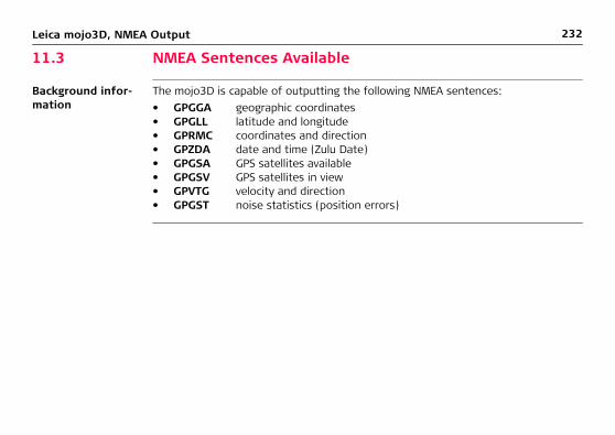
232Leica mojo3D, NMEA Output
11.3 NMEA Sentences Available
Background infor-mation
The mojo3D is capable of outputting the following NMEA sentences:• GPGGA geographic coordinates• GPGLL latitude and longitude• GPRMC coordinates and direction• GPZDA date and time (Zulu Date)• GPGSA GPS satellites available• GPGSV GPS satellites in view• GPVTG velocity and direction• GPGST noise statistics (position errors)

Leica mojo3D, NMEA Output 233

234Leica mojo3D, Virtual Wrench™ Remote Service
12 Virtual Wrench™ Remote Service12.1 Virtual Wrench™
• To make a service request, you must first connect your mojo3D to the Virtual Wrench™ system. Your display will then attempt to connect to Virtual Wrench™, and a service call will be flagged to the service technician. When prompted, enter the cell phone number on which you want the technician to call back.
• After you request service, the service technician can see your device configura-tion, performance, and even the display on your mojo3D. The technician can also remotely press buttons on your behalf, to perform required actions or to guide you through the solution to your problem.
Legal information This software may include product activation and other technology designed to prevent unauthorised use and copying or to provide technical or support services remotely to Leica Geosystems or its authorised reseller.This technology may cause your computer or device to automatically connect to the internet. Additionally, once connected, the software may transmit your serial number/license number to Leica Geosystems and in doing so may prevent uses of the software which are nor permitted; also, the software may transmit other support-related information, such as configurations, usage statistics, or allow or push down-loads of updates to product software.

Leica mojo3D, Virtual Wrench™ Remote Service 235
12.2 Making a Service Request
Making a service request, step-by-step
To make a service request to Virtual Wrench™, carry out the following steps:
4. The phone numbers screen appears. Tap the phone number that you want the service technician to call. If no phone number is stored, tap the Add button and use the on-screen keyboard to enter the number.
5. Tap to send the request with the selected phone number.
6. A dialog confirming the request for support will be displayed. Tap to return to the main navigation screen.
1. On the main navigation screen, tap the service button.
2. On the flyout menu, tap the service request button.
3. On the dialog box that appears:
• tap to green tick symbol to proceed.OR
• tap to connect to Virtual Wrench without sending a service request.

236Leica mojo3D, Virtual Wrench™ Remote Service
12.3 Upgrading Software from Virtual Wrench™
General informa-tion
A new version of software, if available, may be obtained by downloading from Virtual Wrench™.
�Caution Do not turn off the mojo3D while the software upgrade is under way.
Downloading soft-ware, step-by-step
To download a new version of software from Virtual Wrench™, carry out the following steps:1. On the main navigation screen, tap the service button.
2. On the flyout menu, tap the download software button.
3. If you are not already connected to Virtual Wrench a dialog confirming connection will be displayed:
• tap to proceed.OR
tap to abandon the request.

Leica mojo3D, Virtual Wrench™ Remote Service 237
6. Both progress bars (Current Stage and Overall Progress) will be completely full when the download is complete.
7. Tap to start the install.
The mojo3D or mojoXact will automatically restart when the installation is complete.
4. Once connected tap on the item to upgrade. mojo3D or mojoXact (if connected).
Tap to continue.
5. A dialog will be displayed showing the current version and the version available for download:
• tap to proceed.OR
• tap to abandon the request.

238Leica mojo3D, Virtual Wrench™ Remote Service
12.4 Upgrading Software via USB Flash Drive
General informa-tion
A new version of software may be installed from a USB Flash Drive.
Refer to "Appendix B Formatting USB Flash Drives" for important informa-tion about using USB drives with the mojo3D products.
�Caution Do not turn off the mojo3D, or remove the USB Flash Drive, while the software upgrade is under way.
Upgrading soft-ware with a USB Flash Drive, step-by-step
To upgrade the mojo3D software via USB Flash Drive, carry out the following steps:1. The USB interface is on the lower left front of the
mojo3D display. Lift the rubber cover and insert a compatible USB Flash Drive into the USB slot.
mojo3D_010

Leica mojo3D, Virtual Wrench™ Remote Service 239
5. Tap on the software version in the list to select it. Tap to start the install.
6. Both progress bars (Current Stage and Overall Progress) will be completely full when the installation is complete.
• The mojo3D or mojoXact will automatically restart when the installation is complete.
• Remove the USB Flash Drive only when the unit is powered down.
2. On the main navigation screen, tap the service button.
3. On the flyout menu, tap the upgrade from USB button.
4. Tap on the item to upgrade. mojo3D or mojoXact (if connected).
Tap to continue.

240Leica mojo3D, Virtual Wrench™ Remote Service
12.5 Restoring Previous Software Version
General informa-tion
If you perform a software upgrade and there is an unforeseen problem that requires you to re-install a previous version of the software, you can restore the version of the software that was in use before the last upgrade.
�Caution Do not turn off the mojo3D while the software restore is under way.
Restoring previous software version, step-by-step
To restore a previous software version, carry out the following steps:1. On the main navigation screen, tap the service button.
2. On the flyout menu, tap the software restore button.
3. Tap on the item to restore. mojo3D or mojoXact (if connected).
Tap to continue.
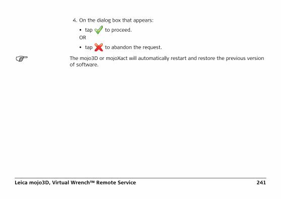
Leica mojo3D, Virtual Wrench™ Remote Service 241
The mojo3D or mojoXact will automatically restart and restore the previous version of software.
4. On the dialog box that appears:
• tap to proceed.OR
• tap to abandon the request.

242Leica mojo3D, Virtual Wrench™ Remote Service
12.6 Backing Up Current Software
General informa-tion
Once you have installed new software by downloading from Virtual Wrench™, you can backup the new software onto a USB Flash Drive. This is useful in speeding up the process when upgrading other mojo3D units.
Refer to "Appendix B Formatting USB Flash Drives" for important informa-tion about using USB drives with the mojo3D products.
�Caution Do not turn off the mojo3D, or remove the USB Flash Drive, while the software back up is under way.
Backing up current software, step-by-step
To back up the current software onto a USB Flash Drive, carry out the following steps:1. The USB interface is on the lower left front of the
mojo3D display. Lift the rubber cover and insert a compatible USB Flash Drive into the USB slot.
mojo3D_010

Leica mojo3D, Virtual Wrench™ Remote Service 243
6. The mojo3D will save a copy of the current software onto the USB Flash Drive.
Tap to close the backup software screen.
Remove the USB Flash Drive only when the unit is powered down.
2. On the main navigation screen, tap the service button.
3. On the flyout menu, tap the backup to USB Flash Drive button.
4. Tap on the item to backup. mojo3D or mojoXact (if connected).
Tap to continue.
5. On the dialog box that appears:
• tap to proceed.OR
• tap to abandon the request.
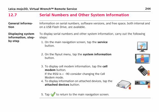
244Leica mojo3D, Virtual Wrench™ Remote Service
12.7 Serial Numbers and Other System Information
General informa-tion
Information on serial numbers, software versions, and free space, both internal and on a USB Flash Drive, are available.
Displaying system information, step-by-step
To display serial numbers and other system information, carry out the following steps:
5. Tap to return to the main navigation screen.
1. On the main navigation screen, tap the service button.
2. On the flyout menu, tap the system information button.
3. To display cell modem information, tap the cell modem button.If the RSSI is < -90 consider changing the Cell Modem mode.
4. To display information on attached devices, tap the attached devices button.

Leica mojo3D, Virtual Wrench™ Remote Service 245

246Leica mojo3D, Care and Transport
13 Care and Transport13.1 Transport
Shipping When transporting the product by rail, air or sea, always use the complete original Leica Geosystems packaging, transport container or cardboard box, or an equivalent, in order to protect against shock and vibration.
13.2 Storage
Temperature limits Respect the temperature limits when storing the equipment, particularly in summer if the equipment is inside a vehicle. Refer to "15 Technical Data" for information about temperature limits.
Leica mojo3D, Care and Transport 247
13.3 Cleaning and Drying
Product and acces-sories
Use only a clean, soft, lint-free cloth for cleaning. If necessary, moisten the cloth with water or pure alcohol. Do not use other liquids; these may attack the polymer compo-nents.
Damp products Dry the product, the transport container, the foam inserts and the accessories at a temperature not greater than 40°C / 104°F and clean them. Do not repack until everything is completely dry. Always close the transport container when using in the field.
Cables and plugs Keep plugs clean and dry. Blow away any dirt lodged in the plugs of the connecting cables.

248Leica mojo3D, Safety Directions
14 Safety Directions14.1 General Introduction
Description • The following directions should enable the person responsible for the product, and the person who actually uses the equipment, to anticipate and avoid opera-tional hazards.
• The person responsible for the product must ensure that all users understand these directions and adhere to them.

Leica mojo3D, Safety Directions 249
14.2 Intended Use
Permitted uses • The mojo3D is intended for agricultural and forestry use only.• The mojo3D is intended to be fitted to agricultural vehicles only. It is not
permitted to install this product in any other vehicles.• Data communication with external appliances.• Guidance of approved agricultural equipment.• Carrying out measurement tasks using various GNSS measuring techniques.• Recording GNSS and point related data.• Measuring raw data and computing coordinates using carrier phase and code
signal from GNSS satellites. (GNSS Systems)
Adverse use • Use of the product without instruction.• Use outside of the intended limits.• Disabling safety systems.• Removal of hazard notices.• Opening the product using tools, for example screwdriver, unless this is specifi-
cally permitted for certain functions.• Modification or conversion of the product.• Use after misappropriation.• Use of products with obviously recognizable damages or defects.

250Leica mojo3D, Safety Directions
• Use with accessories from other manufacturers without the prior explicit approval of Leica Geosystems.
• Inadequate safeguards at the working site, for example when using on the intended site.
�Warning Adverse use can lead to injury, malfunction and damage.It is the task of the person responsible for the equipment to inform the user about hazards and how to counteract them. The product is not to be operated until the user has been instructed on how to work with it.
�Warning Unauthorised modification of agricultural machinery by mounting or installing the product may alter the function and safety of that agricultural machinery.Precautions:Follow the instructions of the machinery manufacturer. If no appropriate instruction is available, ask the machinery manufacturer for instructions before mounting or installing the product.

Leica mojo3D, Safety Directions 251
14.3 Limits of Use
Environment Suitable for use in an atmosphere appropriate for permanent human habitation: not suitable for use in aggressive or explosive environments.
�Danger Local safety authorities and safety experts must be contacted before working in hazardous areas, or in close proximity to electrical installations or similar situations by the person in charge of the product.
14.4 Responsibilities
Manufacturer of the product
Leica Geosystems AG, CH-9435 Heerbrugg, hereinafter referred to as Leica Geosys-tems, is responsible for supplying the product, including the user manual and original accessories, in a completely safe condition.
Manufacturers of non Leica Geosys-tems accessories
The manufacturers of non Leica Geosystems accessories for the product are respon-sible for developing, implementing and communicating safety concepts for their products, and are also responsible for the effectiveness of those safety concepts in combination with the Leica Geosystems product.

252Leica mojo3D, Safety Directions
Person in charge of the product
The person in charge of the product has the following duties:• To understand the safety instructions on the product and the instructions in the
user manual.• To be familiar with local regulations relating to safety and accident prevention.• To inform Leica Geosystems immediately if the product and the application
becomes unsafe.• To ensure that the national laws, regulations and conditions for the operation of
radio transmitters are respected.
�Warning The person responsible for the product must ensure that it is used in accordance with the instructions. This person is also accountable for the training and the deployment of personnel who use the product and for the safety of the equipment in use.

Leica mojo3D, Safety Directions 253
14.5 Hazards of Use
�Warning The absence of instruction, or the inadequate imparting of instruction, can lead to incorrect or adverse use, and can give rise to accidents with far-reaching human, material, financial and environmental consequences.Precautions:All users must follow the safety directions given by the manufacturer and the direc-tions of the person responsible for the product.
�Caution Watch out for erroneous measurement results if the product has been dropped or has been misused, modified, stored for long periods or transported.Precautions:Periodically carry out test measurements and perform the field adjustments indicated in the user manual, particularly after the product has been subjected to abnormal use and before and after important measurements.
�Warning Inadequate securing of the working site can lead to dangerous situations, for example in traffic, on building sites, and at industrial installations.Precautions:Always ensure that the working site is adequately secured. Adhere to the regulations governing safety and accident prevention and road traffic.

254Leica mojo3D, Safety Directions
�Warning Only Leica Geosystems authorised service workshops are entitled to repair these products.
�Caution If the accessories used with the product are not properly secured and the product is subjected to mechanical shock, for example, by blows or falling objects, the product may be damaged or people may sustain injury.Precautions:When setting-up the product, make sure that the accessories are correctly adapted, fitted, secured, and locked in position.Avoid subjecting the product to mechanical stress.
�Caution The product uses the GPS P-Code signal which by U.S. policy may be switched off without notice.
�Warning Incorrect fastening of the external antenna to vehicles or transporters poses the risk of the equipment being broken by mechanical influence, vibration, or airstream. This may result in accident and injury.Precautions:Attach the external antenna professionally. The external antenna must be secured additionally, for example by use of a safety cord. Ensure that the mounting device is correctly attached and able to carry the weight of the external antenna (>1 kg) safely.

Leica mojo3D, Safety Directions 255
�Caution Installing near mechanically moving machine components may damage the product.Precautions:Deflect the mechanically moving machine components as far as possible and define a safe installation zone.
�Caution Beware of inadequate steering if machine is defective like after a crash or other damaging events or alterations to the machine.Precautions:Periodically perform control measurements and field adjustments on the machine as specified in the User Manual.
�Warning While steering or navigating the machine accidents may occur due a) the operator not paying attention to the surroundings (persons, ditches, traffic, etc), or b) malfunctions (… of a system component, interference, etc.).Precautions:The operator assures that the machine is operated, guided and monitored by a qual-ified user (e.g., a licensed driver). The user has to be able to take emergency meas-ures, for example an emergency stop.

256Leica mojo3D, Safety Directions
�Danger If the product is used with accessories, for example, masts, staffs, or poles, you may increase the risk of being struck by lightning. Danger from high voltages also exists near power lines. Lightning, voltage peaks, or the touching of power lines can cause damage, injury and death.Precautions:• Do not use the product in a thunderstorm as you may increase the risk of being
struck by lightning.• Be sure to remain at a safe distance from electrical installations. Do not use the
product directly under or in close proximity to power lines. If it is essential to work in such an environment contact the safety authorities responsible for elec-trical installations and follow their instructions.
• To prevent damages due to indirect lightning strikes (voltage spikes) cables, for example for antenna, power source or modem should be protected with appro-priate protection elements, like a lightning arrester. These installations must be carried out by an authorised specialist.
• If there is a risk of a thunderstorm, or if the equipment is to remain unused and unattended for a long period, protect your product additionally by unplugging all systems components and disconnecting all connecting cables and supply cables.
• If the product has to be permanently mounted in an exposed location, it is advis-able to provide a lightning conductor system. A suggestion on how to design a lightning conductor for the product is given below. Always follow the regulations in force in your country regarding grounding antennas and masts. These instal-lations must be carried out by an authorized specialist.

Leica mojo3D, Safety Directions 257
Lightning conductorsSuggestion for design of a lightning conductor for a GNSS system:1. On non-metallic structures. Protection by air terminals is recommended. An air
terminal is a pointed solid or tubular rod of conducting material with proper mounting and connection to a conductor. The position of four air terminals should be uniformly distributed around the antenna at a distance equal to the height of the air terminal. The air terminal diameter should be 12 mm for copper or 15 mm for aluminium. The height of the air terminals should be 25 cm to 50 cm. All air terminals should be connected to the down conductors. The diameter of the air terminal should be kept to a minimum to reduce GNSS signal shading.
2. On metallic structures. Protection is as described for non-metallic structures, but the air terminals can be connected directly to the conducting structure without the need for down conductors.

258Leica mojo3D, Safety Directions
�Warning If the product is improperly disposed of, the following can happen:• If polymer parts are burnt, poisonous gases are produced, which may impair
health.• By disposing of the product irresponsibly you may enable unauthorised persons
to use it in contravention of the regulations, exposing themselves and third parties to the risk of severe injury and rendering the environment liable to contamination.
Precautions:
Product specific treatment and waste management information can be downloaded from the Leica Geosystems home page at http://www.leica-geosystems.com/treatment or obtained from your Leica Geosystems dealer.
The product must not be disposed of with household waste. Dispose of the product appropriately in accordance with the national regula-tions in force in your country. Always prevent access to the product by unauthorised personnel.
Leica mojo3D, Safety Directions 259
14.6 Electromagnetic Compatibility (EMC)
Description The term Electromagnetic Compatibility is taken to mean the capability of the product to function smoothly in an environment where electromagnetic radiation and elec-trostatic discharges are present, and without causing electromagnetic disturbances to other equipment.
�Warning Electromagnetic radiation can cause disturbances in other equipment.
Although the product meets the strict regulations and standards that are in force in this respect, Leica Geosystems cannot completely exclude the possibility that other equipment may be disturbed.
�Caution There is a risk that disturbances may be caused in other equipment if the product is used in conjunction with accessories from other manufacturers, for example field computers, personal computers, two-way radios, non-standard cables or external batteries.Precautions:Use only the equipment and accessories recommended by Leica Geosystems. When combined with the product, they meet the strict requirements stipulated by the guidelines and standards. When using computers and two-way radios, pay attention to the information about electromagnetic compatibility provided by the manufac-turer.

260Leica mojo3D, Safety Directions
�Caution Disturbances caused by electromagnetic radiation can result in erroneous measure-ments. Although the product meets the strict regulations and standards which are in force in this respect, Leica Geosystems cannot completely exclude the possibility that the product may be disturbed by very intense electromagnetic radiation produced by, for example, nearby radio transmitters, two-way radios, or diesel generators.Precautions:Check the plausibility of results obtained under these conditions.
�Warning If the product is operated with connecting cables attached at only one of their two ends, the permitted level of electromagnetic radiation may be exceeded and the correct functioning of other products may be impaired.Precautions:While the product is in use, connecting cables must be connected at both ends.

Leica mojo3D, Safety Directions 261
Radios or digital cellular phones
Use of the product with radio or digital cellular phone devices:
�Warning Electromagnetic fields can cause disturbances in other equipment, in installations, in medical devices, for example pacemakers or hearing aids and in aircraft. It can also affect humans and animals.Precautions:Although the product meets the strict regulations and standards which are in force in this respect, Leica Geosystems cannot completely exclude the possibility that other equipment may be disturbed or that humans or animals may be affected.• Do not operate the product with radio or digital cellular phone devices in the
vicinity of filling stations or chemical installations, or in other areas where an explosion hazard exists.
• Do not operate the product with radio or digital cellular phone devices near to medical equipment.
• Do not operate the product with radio or digital cellular phone devices in aircraft.

262Leica mojo3D, Safety Directions
14.7 FCC Statement, Applicable in U.S.
�Warning This equipment has been tested and found to comply with the limits for a Class A digital device, pursuant to Part 15 of the FCC Rules.These limits are designed to provide reasonable protection against harmful interfer-ence when the equipment is operated in a commercial environment.This equipment generates, uses, and can radiate radio frequency energy and, if not installed and used in accordance with the instruction manual, may cause harmful interference to radio communications.Operation of this equipment in a residential area is likely to cause harmful interfer-ence in which case the user will be required to correct the interference at his own expense.
�Warning Changes or modifications not expressly approved by Leica Geosystems for compli-ance could void the user’s authority to operate the equipment.

Leica mojo3D, Safety Directions 263
14.8 ICES-003 Statement, Applicable in Canada
�Warning This Class (A) digital apparatus complies with Canadian ICES-003.Cet appareil numérique de la classe (A) est conforme à la norme NMB-003 du Canada.
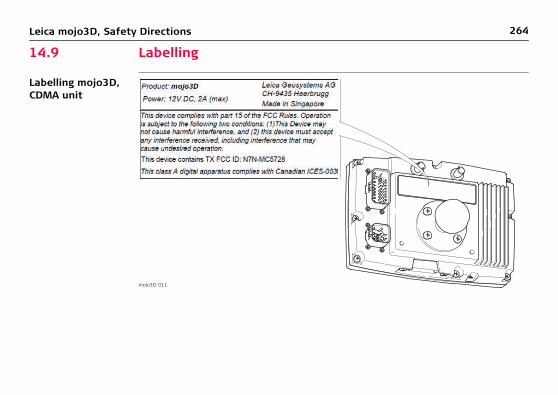
264Leica mojo3D, Safety Directions
14.9 Labelling
Labelling mojo3D, CDMA unit
mojo3D_011

Leica mojo3D, Safety Directions 265
Labelling mojo3D, HSDPA unit
mojo3D_012

266Leica mojo3D, Safety Directions
Labelling Leica Twist, (supplied with Electric Steer Kit)
Labelling Leica mojoXact
mojo3D_021
mojo3D_025

Leica mojo3D, Safety Directions 267

268Leica mojo3D, Technical Data
15 Technical Data15.1 mojo3D Display Technical Data
Design Rugged water-resistant metal housing with a 7" colour display.
User interface
Dimensions
Weight
Power
Display: 7" touch screen for menu navigation, 3D graphics, illuminationKeyboard: on-screen keyboard
Height [cm/inch] Width [cm/inch] Depth [cm/inch]
13.8/5.5 20.2/8.0 5.4/2.1
Weight without RAM mount ball [kg]/[lbs]
1.4/3.1
Consumption [W] External supply voltage
14 Nominal voltage 12 V DC ( )Voltage range 9 V-16 V

Leica mojo3D, Technical Data 269
Environmental specifications
Temperature
Protection against water, dust and sand
Humidity
Operating temperature [°C] Storage temperature [°C]
-10 to +60 -40 to +85
Protection
IP54
Protection
Up to 95 %The effects of condensation are to be effectively counteracted by periodically drying out the mojo3D display.

270Leica mojo3D, Technical Data
Interfaces
Data format for RS232The default values are:
RS232: 2 x AMP 23-pinCAN: 2 x AMP 23-pinUSB: 1 x Front USB
Baud rate: 19200 Data bits: 8Parity: None Stop bits: 1

Leica mojo3D, Technical Data 271
15.2 mojo3D GPS Receiver Technical Data
Performance Performance values quoted are typical values. Performance specifications are subject to GPS system characteristics, US DoD operational degradation, ionospheric and tropospheric conditions, satellite geometry, multipath effects, and the presence of intentional and unintentional interference sources.
Channel configura-tion
12 GPS L1 + 2 SBAS
Horizontal posi-tion accuracy (RMS)
• Single Point L1: 1.5 m• SBAS (GPS only): 0.8 m
Measurement precision (RMS)
• L1 C/A Code: 8 cm• L1 Carrier Phase: 0.8 mm
Data rate • Measurements: Up to 10 Hz• Position: Up to 10 Hz

272Leica mojo3D, Technical Data
Time to first fix • Cold Start: 75 s Typical value, with no almanac or ephemerides, and no approximate position or time.
• Hot Start: 45 s Typical value, with almanac and recent ephemerides saved and approximate posi-tion and time entered.
Signal re-acquisi-tion
L1: <1.0 s (typical)
Time accuracy 20 ns RMS Time accuracy does not include biases due to RF or antenna delay.
Velocity accuracy <0.05 m/s RMS
Velocity 515 m/s US export licensing restricts operation to a maximum of 515 m/s.
Antenna LNA power output
• Output Voltage: 5 V (nominal)• Maximum Current: 100 mA

Leica mojo3D, Technical Data 273
15.3 Wireless Modules Technical Data15.3.1 HSDPA Wireless Module Technical Data
Specifications Type Description
Technology • UMTS with HSDPA Category 87.2 Mbps downlink
• HSUPA Category 55.76 Mbps uplink
• USIM support
Bands • 800/850/900/1900/2100 MHz HSDPAPower class 3 (+24dBm)
• 850/900 MHz GSM/GPRS/EDGEGSM Power class 4/EDGE E2
• 1800/1900 MHz GSM/GPRS/EDGEGSM Power Class 1/EDGE E2

274Leica mojo3D, Technical Data
Data services • 800/850/900/1900/2100 MHz HSDPA• Downlink up to 7.2 Mbps• Uplink up to 5.76 Mbps
• 850/900/1800/1900 MHz GSM/GPRS/EDGE• Downlink up to 236 kbps• Uplink up to 236 kbps
Type Description

Leica mojo3D, Technical Data 275
15.3.2 CDMA Wireless Module Technical Data
Specifications Type Description
Frequency bands • Dual Band• 800 MHz North American cellular band• 1900 MHz North American PCS band
• Supports RX diversity in both 800 MHz and 1900 MHz bands• GPS Band
CDMA standards • IS-856-A (CDMA 1xEV-DO Revision A)• IS-856 (CDMA 1xEV-DO Rel 0)• IS-2000 (CDMA 1xRTT)• IS-95 A/B• IS-707-A Data• IS-637-A SMS• IS-683-A Service Provisioning• IS-683-B (partial)

276Leica mojo3D, Technical Data
Data services • CDMA 1xEV-DO Revision A (IS-856-A)• Forward link up to 3.1 Mbps• Reverse link 1.8 Mbps• CDMA 1xEV-DO Rel 0 (IS-856)• Forward link up to 2.4 Mbps• Reverse link 153.6 kbps• CDMA 1xRTT (IS-2000)• Forward and reverse link speeds up to 153.6 kbps
Safety At least 20 cm (7.88”) separation distance between the antenna and the user’s body must be maintained at all times.
Type Description

Leica mojo3D, Technical Data 277
15.4 Antennas Technical Data15.4.1 GPS Patch Antenna Technical Data
Specifications Type Description
Dielectric antenna • Centre frequency: 1575.45 MHz ± 3 MHz• V.S.W.R.: 1.5:1• Band width: ±5 MHz• Impedance: 50 ohm• Peak gain: > 3 dBic based on 7 cm × 7 cm ground
plane• Gain coverage: > -4 dBic at -90° < 0 < +90° (over
75% volume)• Polarization: RHCP

278Leica mojo3D, Technical Data
LNA/Filter • LNA Gain (without cable): 13 dB/26 dB/28 dB/other• Typical Noise Figure: 1.5 dB• Filter Out Band Attenuation: (f0 = 1575.42 MHz)
• 7 dB Min f0 ± 20 MHz• 20 dB Min f0 ± 50 MHz• 30 dB Min f0 ± 100 MHz
• V.S.W.R.: < 2.0• DC voltage: 2.7 V/3.0 V/3.3 V/5.0 V/3.0 V to
5.0 V/other• DC current: 5 mA/11 mA/15 mA max
Dimensions of base • Lenghth: 44 mm• Width: 35.5 mm• Height: 14 mm
Weight of base < 110 g
Base mounting method Magnetic
Antenna length 5 metre
Antenna type Patch
Type Description

Leica mojo3D, Technical Data 279
Temperature • Operating temperature: -40°C to +85°C• Storage temperature: -45°C to +100°C
Vibration Sine sweep 1g (0-p) 10~50~10 Hz each axis
Connector Fakra (Blue; Key: C Type)
Humidity 95%~100% RH
Protection against water Waterproof
Type Description

280Leica mojo3D, Technical Data
15.4.2 Cellular Antenna Technical Data
Specifications Type Description
Dimensions • Length: 115 mm• Width: 22 mm• Thickness: 4 mm
Weight 56 g
Compatibility • Frequency Range: 824-960 MHz, 1710-1990 MHz• Bandwidth: 136/280 MHz• V.S.W.R.: < 1.5• Gain: 2 dBi• Maximum power input: 60 W• Input impedance: 50
Antenna type Dipole
Polarization type Vertical
Length 3 metre
Connector Fakra (Bordeaux; Key: D Type)
Cable type RG174

Leica mojo3D, Technical Data 281
Operating charac-teristics
Antenna mounting method
Adhesive
Type Description
Type Band
CDMA800 and GSM900 DCS1800 and PCS1900
Frequency (MHz) 824 964 1710 1990
Return Loss (dB) -18.48 -20.18 -15.65 -9.51
SWR 1.233 1.335 1.466 1.866

282Leica mojo3D, Technical Data
15.4.3 mojoXact and mojoXact Plus Red Antenna Technical Data
Design Polymer moulded enclosure.
Dimensions
Weight
Gain
Frequency
Length [cm] Width [cm] Height [cm]
20.9 22.7 28.2
Weight [kg]/[lbs]
0.7/1.54
Gain [dBi]
27
Frequency [MHz]
L1: 1575 + 23.0L2: 1236 + 18.0

Leica mojo3D, Technical Data 283
Power Consumption [W] External supply voltage
0.158 Nominal voltage 5.0 V DC ( )Voltage range 4.5 V-18 V

284Leica mojo3D, Technical Data
Environmental specifications
Temperature
Protection against water, dust and sand
Humidity
Operating temperature [°C] Storage temperature [°C]
-30 to +70 -40 to +85
Ingress Protection
IP66
Protection
Up to 95 %The effects of condensation are to be effectively counteracted by periodically drying out mojoXact Red Antenna.

Leica mojo3D, Technical Data 285
Antenna Antenna Type Gain [dBi]
Connector Frequency band [MHz]
Impedance [Ohm]
868 MHz Antenna
1/2 wave Dipole
2.5 RPTNC 860-880 50
900 MHz Spread Spec-trum Antenna
1/2 wave Dipole
2.0 RPTNC 902-928 50

286Leica mojo3D, Technical Data
15.4.4 mojoXact Black GeoPRO Antenna Technical Data
Design Polymer moulded enclosure.
Dimensions
Weight
Power
Length [cm] Width [cm] Height [cm]
20.9 22.7 28.2
Weight [kg]/[lbs]
0.65/1.43
Consumption [W] External supply voltage
0.059 Nominal voltage 5.0 V DC ( )Voltage range 2.7 V-6 V

Leica mojo3D, Technical Data 287
Environmental specifications
Temperature
Protection against water, dust and sand
Humidity
Operating temperature [°C] Storage temperature [°C]
-30 to +70 -40 to +85
Protection
IP66
Protection
Up to 95 %The effects of condensation are to be effectively counteracted by periodically drying out mojoRTK Black Antenna.

288Leica mojo3D, Technical Data
Antenna Valid for Antenna Gain [dBi] Connector Frequency band [MHz]
Global Whip antenna (Cellular)
0 RPTNC 900
Global Pin wheel antenna (GNSS)
27, receive only
SMA L1: 1575 ± 3.0

Leica mojo3D, Technical Data 289
15.5 mojoXact Technical Data
Design Sealed cast aluminium.
User interface 3 LEDs.
Dimensions
Weight
Power
Length [cm] Width [cm] Height [cm]
15.1 16.6 4.9
Weight [kg]/[lbs]
0.918/2.1
Consumption [W] External supply voltage
7 Nominal voltage 12 V DC ( )Voltage range 19 V-16 V

290Leica mojo3D, Technical Data
Environmental specifications
Temperature
Protection against water, dust and sand
Humidity
Operating temperature [°C] Storage temperature [°C]
-30 to +70 -40 to +85
Ingress Protection
IP66
Protection
Up to 95 %The effects of condensation are to be effectively counteracted by periodically drying out the mojoXact.

Leica mojo3D, Technical Data 291
Interfaces Expansion cable: 2 x CAN BUS2 x Serial RS2321 x Power Out (Radio)1 x Switch Input1 x Power Input + Accessory Switch1 x Ethernet1 x Radar Speed Output
USB: 1 x rear USB

292Leica mojo3D, Technical Data
15.6 mojoXact GPS Receiver Technical Data
Channel configura-tion
GPS120 Channels - Up to 60 L1/L2 satellitesSignal Tracking GPS: L1, L2GLONASS: L1, L2
Horizontal posi-tion accuracy (RMS)
• Single Point L1: 1.5 m• Single Point L1/L2: 1.2 m• RTK (RT-2): 1 cm + 1 ppm
Measurement precision (RMS)
Fully independent code and carrier measurements:
Data rate • Measurements: Up to 100 Hz• Position: Up to 20 Hz
Code GPS GLO
L1 C/A code 4 cm 8 cm
L1 carrier phase 0.5 mm 1.0 mm
L2 carrier phase (L2 P for GLONASS) 1.0 mm 1.0 mm

Leica mojo3D, Technical Data 293
Time to first fix • Cold Start: 50 s Typical value, with no almanac or ephemerides, and no approximate position or time.
• Hot Start: 35 s Typical value, with almanac and recent ephemerides saved and approximate posi-tion and time entered.
Signal re-acquisi-tion
L1: <0.5 s (typical)L2: <1.0 s (typical)
Time accuracy 20 ns RMS Time accuracy does not include biases due to RF or antenna delay.
Velocity accuracy <0.05 m/s RMS
Velocity 515 m/s US export licensing restricts operation to a maximum of 515 m/s.
Antenna LNA power output
• Output Voltage: 5 V (nominal)• Maximum Current: 100 mA

294Leica mojo3D, Technical Data
15.7 mojoXact Plus Technical Data
Design Sealed cast aluminium.
User interface 3 LEDs.
Dimensions
Weight
Power
Length [cm] Width [cm] Height [cm]
15.1 16.6 4.9
Weight [kg]/[lbs]
0.946/2.1
Consumption [W] External supply voltage
7 Nominal voltage 12 V DC ( )Voltage range 9 V-16 V

Leica mojo3D, Technical Data 295
Environmental specifications
Temperature
Protection against water, dust and sand
Vibration and Shock
Humidity
Operating temperature [°C] Storage temperature [°C]
-30 to +70 -40 to +85
Ingress Protection
IP66
Vibration Shock
3.5g up to 200Hz 40g 6mS
Protection
Up to 95 % According to IEC 60068-2-30
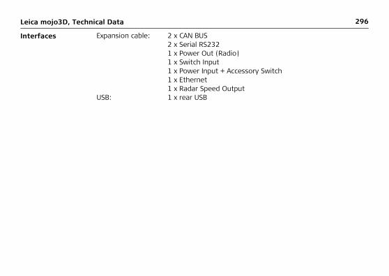
296Leica mojo3D, Technical Data
Interfaces Expansion cable: 2 x CAN BUS 2 x Serial RS2321 x Power Out (Radio)1 x Switch Input1 x Power Input + Accessory Switch1 x Ethernet1 x Radar Speed Output
USB: 1 x rear USB

Leica mojo3D, Technical Data 297
15.8 mojoXact Plus GPS Receiver Technical Data
Performance Performance values quoted are typical values. Performance specifications are subject to GPS system characteristics, US DoD operational degradation, ionospheric and tropospheric conditions, satellite geometry, multipath effects and the presence of intentional and unintentional interference sources.
Channel configura-tion
GPS120 Channels - Up to 60 L1/L2 satellitesSignal Tracking GPS: L1, L2, L2C, L5GLONASS: L1, L2
Horizontal posi-tion accuracy (RMS)
• Single Point L1: 1.5 m• Single Point L1/L2: 1.2 m• RTK (RT-2): 1 cm + 1 ppm

298Leica mojo3D, Technical Data
Data rate • Measurements: Up to 100 Hz• Position: Up to 20 Hz
Time to first fix • Cold Start: 50 s Typical value, with no almanac or ephemerides, and no approximate position or time.
• Hot Start: 35 s Typical value, with almanac and recent ephemerides saved and approximate posi-tion and time entered.
Signal re-acquisi-tion
L1: <0.5 s (typical)L2: <1.0 s (typical)
Time accuracy 20 ns RMS Time accuracy does not include biases due to RF or antenna delay.
Velocity accuracy <0.05 m/s RMS
Velocity <515 m/s US export licensing restricts operation to a maximum of 515 m/s.
Antenna LNA power output
• Output Voltage: 5 V (nominal)• Maximum Current: 100 mA

Leica mojo3D, Technical Data 299
15.9 Conformity to National Regulations15.9.1 mojo3D
Conformity to national regula-tions
• FCC Part 15 (applicable in US).• Hereby, Leica Geosystems AG, declares that the mojo3D is in compliance with the
essential requirements and other relevant provisions of Directive 1999/5/EC. The declaration of conformity may be consulted at http://www.leica-geosystems.com/ce.
Class 1 equipment according to European Directive 1999/5/EC (R&TTE) can be placed on the market and be put into service without restrictions in any EEA Member state.
• The conformity for countries with other national regulations not covered by the European directive 1999/5/EC has to be approved prior to use and operation.
Frequency band Type Frequency band [MHz]
GPS receiver L1: 1575 ± 23
CDMA 850/1900
HSDPA 800/850/900/1800/1900/2100

300Leica mojo3D, Technical Data
Output power CDMA 24dBm/HSDPA upto 32dBm
Antenna Type Antenna Gain [dBi] Connector Frequency band [MHz]
GPS receiver L1 Patch (GNSS) 27 Fakra (Blue; Key: C Type)
L1: 1575 ± 33
Cellular 2 Fakra (Bordeaux; Key: D Type)
824-960 MHz, 1710-1990 MHz

Leica mojo3D, Technical Data 301
15.9.2 mojoXact
Conformity to nationalregulations
Frequency band
Output power GPS receiver, reference data radio: receive only on the mojoXact.
• Hereby, Leica Geosystems AG, declares that the mojoXact is in compliance with the essential requirements and other relevant provisions of Directive 1999/5/EC. The declaration of conformity may be consulted at http://www.leica-geosystems.com/ce.
Type Frequency band [MHz]
GPS receiver L1: 1575.42 ± 23L2: 1236.00 ± 18.3
Reference data radio 868 or 900

302Leica mojo3D, Technical Data
Antenna Type Antenna Gain [dBi] Connector Frequency band [MHz]
GPS receiver L1/L2
Pin wheel antenna (GNSS)
27 SMA L1: 1575 ± 33L2:1236 ± 18.3
Reference data radio
Whip antenna 1.5 RPTNC 868 or 900

Leica mojo3D, Technical Data 303
15.9.3 mojoXact Plus
Conformity to nationalregulations
• FCC Part 15 (applicable in US)• C-Tick (applicable in AUS)• CE EMC Directive 2004/108/EC• Hereby, Leica Geosystems AG, declares that the mojoXact Plus is in compliance
with the essential requirements and other relevant provisions of Directive 1999/5/EC. The declaration of conformity may be consulted at http://www.leica-geosystems.com/ce.
Class 1 equipment according European Directive 1999/5/EC (R&TTE) can be placed on the market and be put into service without restrictions in any EEA Member state.
• The conformity for countries with other national regulations not covered by the European directive 1999/5/EC has to be approved prior to use and operation.
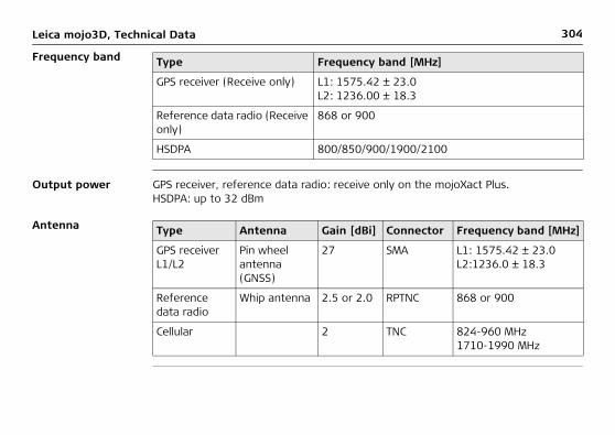
304Leica mojo3D, Technical Data
Frequency band
Output power GPS receiver, reference data radio: receive only on the mojoXact Plus.HSDPA: up to 32 dBm
Antenna
Type Frequency band [MHz]
GPS receiver (Receive only) L1: 1575.42 ± 23.0L2: 1236.00 ± 18.3
Reference data radio (Receive only)
868 or 900
HSDPA 800/850/900/1900/2100
Type Antenna Gain [dBi] Connector Frequency band [MHz]
GPS receiver L1/L2
Pin wheel antenna (GNSS)
27 SMA L1: 1575.42 ± 23.0L2:1236.0 ± 18.3
Reference data radio
Whip antenna 2.5 or 2.0 RPTNC 868 or 900
Cellular 2 TNC 824-960 MHz1710-1990 MHz

Leica mojo3D, Technical Data 305

306Leica mojo3D, International Limited Warranty, Software License Agreement
16 International Limited Warranty, Software License Agreement
International Limited Warranty
This product is subject to the terms and conditions set out in the International Limited Warranty which you can download from the Leica Geosystems home page at http://www.leica-geosystems.com/internationalwarranty or collect from your Leica Geosystems distributor.
The foregoing warranty is exclusive and is in lieu of all other warranties, terms or conditions, express or implied, either in fact or by operation of law, statutory or otherwise, including warranties, terms or conditions of merchantability, fitness for a particular purpose, satisfactory quality and non-infringement, all of which are expressly disclaimed.
Software Licence Agreement
This product contains software that is preinstalled on the product, or that is supplied to you on a data carrier medium, or that can be downloaded by you online pursuant to prior authorization from Leica Geosystems. Such software is protected by copy-right and other laws and its use is defined and regulated by the Leica Geosystems Software Licence Agreement, which covers aspects such as, but not limited to, Scope of the Licence, Warranty, Intellectual Property Rights, Limitation of Liability, Exclusion of other Assurances, Governing Law and Place of Jurisdiction. Please make sure, that at any time you fully comply with the terms and conditions of the Leica Geosystems Software Licence Agreement.

Leica mojo3D, International Limited Warranty, Software License Agreement 307
Such agreement is provided together with all products and can also be referred to and downloaded at the Leica Geosystems home page at http://www.leica-geosystems.com/swlicense or collected from your Leica Geosystems dealer.
You must not install or use the software unless you have read and accepted the terms and conditions of the Leica Geosystems Software Licence Agreement. Installa-tion or use of the software or any part thereof, is deemed to be an acceptance of all the terms and conditions of such licence agreement. If you do not agree to all or some of the terms of such licence agreement, you may not download, install or use the software and you must return the unused software together with its accompa-nying documentation and the purchase receipt to the dealer from whom you purchased the product within ten (10) days of purchase to obtain a full refund of the purchase price.
308Leica mojo3D, mojo3D Enhancements
Appendix A mojo3D Enhancements
A.1 mojo3D with Single Section Control
General informa-tion
• Single section control is available on the mojo3D through the addition of the optional Port Expansion Cable.
• The Port Expansion Cable has an isolated switched relay output capable of 30 A, which allows the single section control to be used in a wide range of applications.
• The switched relay output on the mojo3D Port Expansion Cable can be connected to a third-party equipment to control a single section or master switch.
Accessories required
• mojo3D Port Expansion Cable

Leica mojo3D, mojo3D Enhancements 309
Installation To install single-section control, carry out the following steps:
The relay has a normally open contact which is closed when the mojo3D switches the output on. The mojo3D can be configured to set the relay to normally closed operation by selecting Planter as the Implement Mode.
1. Connect the port expansion cable to the mojo3D.
2. Connect two wires from the relay to the equipment which is to be switched.
mojo3D_013
mojo3D_020

310Leica mojo3D, mojo3D Enhancements
Software configu-ration, step-by-step
3. Tap until the Section Controller / Implement mode screen is displayed.
4. Tap Single Section in the list at the left of the screen, to select it as the section controller.
5. Tap to select implement mode:• Sprayer Mode: is used for most situations, this allows the section control to
be optimally setup for general applications.• Planter Mode: optimises the system for operating a planter and if selected,
changes the relay to normally closed while the mojo3D is switched on, and the section output is off.
6. Tap to continue.
7. Tap mojo3D to select the it as master input source.
1. On the main navigation screen, tap the settings button.
2. On the flyout menu, tap the Vehicle Setup button.

Leica mojo3D, mojo3D Enhancements 311
8. Tap to select the input mode:
The Master Input Mode selection will depend on the configuration of the individual system:
• Touch: the coverage mapping is activated by touching a button on the screen.• Master Input: the coverage mapping is activated by sensing a voltage
connected to the Master wire on the mojo3D power cable.
9. Tap to continue. The section control setup screen is shown with a single section setup.
10. Tap the section width field. Use the on–screen number pad to enter the width
measurement then tap on the number pad when finished.
11. Configure automatic section control by entering the additional information on the screen:• Overlap limit: the percentage amount of overlap that is to be allowed before
the section is turned off.• Low Speed Shutoff: the minimum travel speed for a section before it is
turned off.• Off latency: the number of seconds it takes from the section being turned off
until the actual application stops.• On latency: the number of seconds it takes from the section being turned on
until the actual application starts.

312Leica mojo3D, mojo3D Enhancements
Refer to "7 Automatic Section Control" for a detailed description of settings.
12. When you have entered all required data on the screen tap to continue.

Leica mojo3D, mojo3D Enhancements 313
A.2 mojo3D with Multi Section Control Kit
General informa-tion
• Multi section control is available as an option for the mojo3D.• The multi section control kit uses the Leica AS400 section controller to provide
multi section control. This option allows for multiple individual sections to be automatically controlled, in order to minimise overlap. Leica AS400 provides up to 13 section control.
• The interface for this control is a simple voltage control, which allows the multi section control kit to be used with a wide range of third party rate controllers.
• The interface provides a master input sense from a single or dipole switch.
Direct Section Control Kits are also available. For Further Information see your Leica Geosystems Dealer or refer to www.virtualwrench.com
Accessories required
• mojo3D Port Expansion Cable• Multi Section Control Kit or Direct Section Control Kit

314Leica mojo3D, mojo3D Enhancements
Installation
a) Port expansion cableb) AS400 bus cablec) Bus power cabled) AS400
To install multi section control, carry out the following steps:1. Connect the Port Expansion Cable to the mojo3D.
mojo3D_013

Leica mojo3D, mojo3D Enhancements 315
2. Connect the AS400 bus cable to the Port Expansion Cable.
If the electric steer kit is also installed then the AS400 bus cable must be connected to the QuickSteer bus cable which will be connected to the port expansion cable.
3. Connect the bus power cable to a clean 12 volt power source and to the AS400 bus cable.
4. Connect the circular connector on the AS400 bus cable to the AS400.
5. Connect the controller interface cable to the remaining port on the AS400.6. Installation instructions for the controller interface cable will be supplied with the
cable which is available separately.
mojo3D_015

316Leica mojo3D, mojo3D Enhancements
Power:• The power supply for the multi section control kit must be able to supply 8 A
continuously from a permanent 12 V supply.• If the Electric Steer Kit is also being used, the power supply must be able to
supply 13 A continuously at 12 V, and the multi section control kit must be connected closest to the power source.
• A 5 m (16.4 ft) cable is supplied so that direct connection to the battery is possible if required.
The Leica AS400 section controller should be located in any convenient place in the vehicle cabin.
Software configu-ration, step-by-step
1. On the main navigation screen, tap the settings button.
2. On the flyout menu, tap the Vehicle Setup button.
3. Tap until the Section Controller / Implement mode screen is displayed.4. Tap Leica AS400, to select it as the section controller.

Leica mojo3D, mojo3D Enhancements 317
5. Tap to select implement mode:• Sprayer Mode: is used for most situations, this allows the section control to
be optimally setup for general applications.• Planter Mode: optimises the system for operating a planter and if selected,
reverses the polarity of the Leica AS400 normal operation.
6. Tap to continue.7. Tap to select the master input source, and input mode:
The Master Input Source & Input Mode selection will depend on the config-uration of the individual system:
• mojo3D / Touch: the on screen coverage mapping is activated by touching a button on the screen.
• mojo3D / Master Input: the on screen coverage mapping is activated by sensing a voltage connected to the Master wire on the mojo3D power cable.
• Leica AS400 / Single: the on screen coverage mapping is activated by sensing a voltage connected to the Master wire on the Leica AS400 controller port. This is only available with specific rate controller cables.
• Leica AS400 / Dipole Switch: the on screen coverage mapping is activated by sensing a pair of switching wires. This is only available with specific rate controller cables.
8. Tap , the section control setup screen is shown.

318Leica mojo3D, mojo3D Enhancements
9. The section control setup screen initially shows one section, as a single blue bar near the top of the screen. To set the number of sections, tap the number of
sections field, enter the number of sections, and tap .10. The blue bar will be divided showing the number of sections set. To set the width
of the first section, tap the section width field, enter the width and tap .
11. Tap at the top right corner of the screen, the selected section in the bar will be coloured blue. Set the width of the section the same way by tapping on the section width field.
When all sections widths are correctly set, the Implement Width shown should match the total width of the physical implement.

Leica mojo3D, mojo3D Enhancements 319
12. Configure automatic section control by entering the additional information on the screen:• Overlap limit: the percentage amount of overlap that is to be allowed before
the section is turned off.• Low Speed Shutoff: the minimum travel speed for a section before it is
turned off.• Off latency: the number of seconds it takes from the section being turned off
until the actual application stops.• On latency: the number of seconds it takes from the section being turned on
until the actual application starts.
Refer to "7 Automatic Section Control" for a detailed description of settings.
13. When you have entered all required data on the screen tap to continue.

320Leica mojo3D, mojo3D Enhancements
A.3 mojo3D with GeoPRO Antenna
You should also refer to the installation hints specific to your tractor type and/or steer kit if applicable. These may be obtained at www.virtualwrench.com
General informa-tion
The Leica GeoPRO plus GLONASS option increases the receiver performance through the use of a specially tuned antenna element and ability to receive GLONASS satellite signals. The increased number of usable satellites means better coverage in situa-tions where GPS may normally have trouble. The external cell modem antenna improves coverage for Virtual Wrench™ in marginal signal reception areas. A GLONASS unlock code is also required to receive GLONASS satellite signals. For further information refer to "A.5 Redeeming a System Option Voucher".

Leica mojo3D, mojo3D Enhancements 321
Prepare the GeoPRO antenna
1. Clean the cab roof to prepare for the installation of the GeoPRO antenna. Approved cleaning products are denatured alcohol and Windex® glass cleaner.
Start all antenna cable connections by hand before using the wrench to tighten. Do not overtighten the cable connections. Run the threads to the end and tighten only 1/8 turn more.
2. Connect the cable with the small connector to the GeoPRO antenna.3. Insert the thread of the whip antenna cable as shown, bring on the washer and
fix with the nut.4. Run the cables through the circular slot provided on the bottom side of the cover.
Align each cable with the slot and push it into the slot using the antenna cable grommets and antenna cable supports provided.
5. You have several options for how you want the cables to exit the antenna cover. Choose whatever works best for your application.
2
3
4
5
mojo3D_022

322Leica mojo3D, mojo3D Enhancements
GeoPRO antenna position
The GeoPRO antenna should be mounted on the vehicle roof:• on the centre line of the implement, which may not necessarily be the centre of
the vehicles roof• as far forward as possible on the flat level part of the roof• not obstructed by exhausts, flashing lights or any other objects
6. Install the whip antenna on the GeoPRO antenna.
Keep in mind that the whip antennas should be mounted on the GPS antennas to buckle backwards if needed.
GeoPRO_002

Leica mojo3D, mojo3D Enhancements 323
Mount the GeoPRO antenna
.
1. Use the supplied cleaning wipes to clean the installation area.2. Remove the protective strip on the double-sided tape.
Be careful removing the backing tape from the sticking blocks. Make sure that you only peel off the tape and do not rip the adhesive from the backing tape.
3. Mount the GeoPRO antenna on the vehicle roof.
Keep in mind that the GeoPRO antenna should mount with the whip antenna in the forward position.
3
2
GeoPRO_003

324Leica mojo3D, mojo3D Enhancements
• The cables must not be cut, kinked or bent tightly, as their performance will be degraded and system failure may result.
• Cables should be routed neatly back to the mojo3D.• The antenna must be mounted horizontally and not on an angle to ensure best
signal reception possible.
4. Connect the blue GPS antenna cable to the blue connector on the rear of the mojo3D display.
5. Connect the purple cell modem antenna cable to the purple connector on the rear of the mojo3D display.
GeoPRO_004
54

Leica mojo3D, mojo3D Enhancements 325
A.4 mojo3D with mojoXact Kit
General informa-tion
• The Leica mojoXact brings RTK positioning and advanced steering kit options to the mojo3D display.
• The Leica mojoXact kit brings superior performance in positioning.
The GPS Patch Antenna supplied with the mojo3D is not required when operating with a Leica mojoXact. A new supplied GPS Antenna is supplied with the mojoXact for use with the mojo3D.
Accessories required
• Leica mojoXact• Leica mojoXact Port Expansion Cable• mojo3D Port Expansion Cable
Optional accesso-ries
• mojo3D to mojoXact Port Expansion Extension Cable

326Leica mojo3D, mojo3D Enhancements
A.4.1 Leica mojoXact
mojoXact
a) Green LEDb) Orange LEDc) Red LEDd) USB portmojo3D_026
ab
d
c
Module Function
Green LED Green LED lights when Leica mojoXact Steer Kit system is ready.
Orange LED Orange LED lights when Leica mojoXact system has a guidable position.
Red LED Red LED lights when the Leica mojoXact has power.
USB port Used for data transfer and storage and Leica mojoXact software upgrades.

Leica mojo3D, mojo3D Enhancements 327
A.4.2 Installation
Before installation This user manual contains sufficient information for installation and safe use. However, Leica Geosystems recommends that installation of the Leica mojoXact equipment be performed by a qualified technician, because installation requires making electrical connections.
• The following instructions are to be used as a general guide during the installa-tion of the Leica mojoXact. For more specific instructions, please visit www.virtualwrench.com to view additional platform information and recom-mended vehicle settings.
• The system will not operate at peak performance if steering joints and linkage assemblies are not within the manufacturer's specifications. Check for worn steering components by turning the steering wheel. As the steering wheel is turned, the wheels should begin to move. If the results are unsatisfactory, please consult your vehicle manufacturer's maintenance manual.
• Install the system in a clean and dry workshop environment. Failure to do so may result in electrical short-circuits or other product malfunctions. The antenna mounting tape will not stick properly if there is any moisture on the roof of the vehicle at installation.
• Route and secure all cables and wiring to ensure that they do not chafe or rub, thus causing premature failure.

328Leica mojo3D, mojo3D Enhancements
• The average installation time will vary, but is usually two to four hours per vehicle. The time of installation may vary with vehicle type.

Leica mojo3D, mojo3D Enhancements 329
A.4.3 Antenna Installation
Position of the GPS antennas
1. First find the locations that allow the antennas to have a large separation and be as close to the front of the tractor as possible.
2. Mark out these locations on the roof of the tractor.
• The antennas must be square with one another, meaning that one antenna should not be closer to the back of the vehicle than the other.
• Optional Antenna Adaptor brackets are available. Visit www.virtualwrench.com for more information.
a) Red (Black) antenna offsetb) Center linec) Measurement dotsd) Antenna separation, minimum
distance 80 cm/32”

330Leica mojo3D, mojo3D Enhancements
Prepare the GPS antennas
1. Clean the cab roof to prepare for the installation of the GPS antennas. Approved cleaning products are denatured alcohol and Windex® glass cleaner.
Start all antenna cable connections by hand before using the wrench to tighten. Do not overtighten the cable connections. Run the threads to the end and tighten only 1/8 turn more.
2. Connect the color coded cables to the mojoXact black (GeoPRO) and mojoXact red antennas - black coded cable to black antenna, red to red.
3. Insert the thread of the whip antenna cable as shown, bring on the washer and fix with the nut. The whip antenna cables are also color coded.
4. Run the cables through the circular slot provided on the bottom side of the cover. Align each cable with the slot and push it into the slot using the antenna cable grommets and antenna cable supports provided.
2
3
4
5
mojo3D_022

Leica mojo3D, mojo3D Enhancements 331
5. You have several options for how you want the cables to exit the antenna cover. Choose whatever works best for your application.
6. Install a whip antenna on each of the two GPS antennas.
The whip antennas are color coded to the GPS antennas, red to red and black to black.
Keep in mind that the whip antennas should be mounted on the GPS antennas to buckle backwards if needed.
mojoRTK_006

332Leica mojo3D, mojo3D Enhancements
Mount the GPS antennas
.
1. Remove the protective strip on the double-sided tape.
The cables must not be cut, kinked, or bent tightly or their performance will be degraded and may even result in system failure.
Be careful removing the backing tape from the sticking blocks. Make sure that you only peel off the tape and do not rip the adhesive from the
mojo3D_023
1
2
3

Leica mojo3D, mojo3D Enhancements 333
backing tape. Keep in mind that both GPS antennas should mount with the whip antennas in the forward position.
Route the cables through existing grommets if possible; if not, modification may be required to route the cables to the desired location. If creating a new entry point, make sure to use a grommet to protect the cables.
2. Mount the red antenna in its previously marked out position, ensuring that it is on the right–hand side of the vehicle when looking forward from the operator's seat.
3. Mount the black (GeoPRO) antenna accordingly on the left-hand side.

334Leica mojo3D, mojo3D Enhancements
A.4.4 Leica mojoXact Installation
Before installation Before installing the Leica mojoXact, you must do the following. For more informa-tion on each of these important steps, please refer to the installation hints specific to your vehicle or Leica Steer Ready Kit. These installation hints are at www.virtualwrench.com, How to Guides.
1. Refer to any available installation hints specific to your tractor type.This information may be available from the web site at www.virtualwrench.com, or may have been supplied with your system. The method of completion of the following tasks will be determined by the make and model of your vehicle.
2. Check or prepare for mojoXact power connection.Verify that you have a mojoXact port expansion cable and a mojo3D port expan-sion cable available.
3. Install steering cable (CAN bus).There are many possible combinations for this step, depending on vehicle type, or Leica Steer Kit used, or both. The cable specific to your vehicle should be purchased with your system.

Leica mojo3D, mojo3D Enhancements 335
mojoXact installa-tion Use caution with metal work; it may be sharp and could cause injury if care
is not taken.1. Carefully remove the mojoXact from its packaging. The mojoXact can be mounted
in any direction. There is no need to mount it exactly flat. The mojoXact should be mounted in an out of the way location, so that it will not obstruct the opera-tion of the vehicle such as pedals.
2. Attach the mojoXact to a secure location using the four mounting points.
Verify that the mojoXact is firmly mounted and cannot move. If movement is possible, performance may be degraded.
Connecting cables The mojo3D port expansion cable and mojoXact port expansion cable is used to connect the mojoXact to the mojo3D display unit.
For further information, refer to www.virtualwrench.com.

336Leica mojo3D, mojo3D Enhancements
Connect the mojo3D to a mojoXact
To connect the mojo3D hardware to the mojoXact hardware, referring to the diagram, carry out the following steps:
mojo3D_027
1
6
6
6
3
5
4
2

Leica mojo3D, mojo3D Enhancements 337
1. Attach the black GeoPRO GPS antenna cables (Blue and Purple plugs) to the Blue and Purple antenna sockets on the back of the mojo3D.
2. Attach the red GPS antenna cables (Green and Red plugs) to the Green and Purple antenna sockets on the mojoXact.
3. Connect the mojo3D port expansion cable to the mojo3D.4. Connect the mojoXact port expansion cable to the mojoXact.5. Connect the green cable on the mojo3D port expansion cable to the green cable
on the mojoXact cable. Note that a mojo3D to mojoXact port expansion exten-sion cable is available if more length (up to 2m) is required due to the positioning of the mojo3D and mojoXact.
6. Ensure that the power cable and any other required cables are connected correctly.

338Leica mojo3D, mojo3D Enhancements
Initial software configuration, step-by-step
The mojoXact/mojoXact Plus can be selected as the device to setup when the mojo3D is first turned on, or it can be setup by the operator accessing the setup wizard at any time. If the mojoXact/mojoXact Plus is selected when the mojo3D is turned on for the first time, then follow steps 4 and onwards below.
To setup the mojoXact/mojoXact Plus using the setup wizard, carry out the following steps:1. On the main navigation screen, tap the Settings button.
2. On the flyout menu, tap the setup wizard button.
3. On the attached device selection screen, tap the
mojoXact/mojoXact Plus button and tap to continue.
The brightness screen appears.
4. Adjust the slider to vary the brightness of the screen, by tapping and .
5. Tap to continue.
The country selection screen appears.

Leica mojo3D, mojo3D Enhancements 339
6. On the country selection screen, tap the button labelled with the flag of your country. Countries are listed in alphabetical order on the screen. If the required
flag is not visible, tap to display more flags.
7. After making your selection, tap to continue.
The languages screen appears.8. On the languages screen, tap the button labelled with your required language.
9. Tap to continue.
The UTC time screen appears.
10. On the UTC time screen, tap and to enter the local time, expressed as an offset from UTC (Coordinated Universal Time) time. Each tap will change the time offset by 30 minutes.
11. After selection, tap to continue.
The units selection screen appears.

340Leica mojo3D, mojo3D Enhancements
14. On the mode selection screen, tap the buttons to select:• top-down mode: either north is at the top of the map screen, or the direction
of the front of the vehicle is at the top of the map screen, and• display mode: day mode, night mode, or automatic switch between modes.
15. After making your selections, tap to continue.
The lightbar mode screen appears.
The default lightbar mode is the Leica Geosystems Smart lightbar which uses both cross track error and heading error to guide you to the line. The other choice offered is the traditional Crosstrack only lightbar.
To configure the lightbar settings, carry out the following steps:
12. On the units selection screen, tap the buttons to select:• Lengths may be measured in metric, Imperial, or US Standard units. • Speeds may be measured in metric, Imperial, or US Standard units. • Areas may be measured in metric, Imperial, or US Standard units. The Imperial
acre is the defined international acre, and the US acre is the slightly smaller US Survey acre.
13. After making your selections, tap to continue.
The mode selection screen appears.

Leica mojo3D, mojo3D Enhancements 341
16. On the Lightbar Mode screen, select:• Smart to use the smart lightbar, or• Crosstrack to use the traditional cross track lightbar.
17. If you selected Smart, tap to continue through the System Settings Wizard.
The Cell Modem Setup screen appears - go to step 20 below.18. If you selected Crosstrack, more configuration options are now available on the
Lightbar Mode screen. • Chase: when Chase mode is on (green), the lightbar represents where the line
is relative to where the vehicle is, and to steer to the line, you steer towards the light - that is, you chase the light. When Chase mode is off (gray) the lightbar represents the position of the vehicle relative to the line and to steer the vehicle onto the line, you steer away from the light to "pull" the light to the line.
• Crosstrack error per lightbar segment: this setting determines how much cross track error is represented by each segment in the lightbar. A small number makes the lightbar more sensitive and hard to follow, but more accurate. A large number makes the lightbar less sensitive and easy to follow, but less accurate.
Choose your lightbar settings.
19. Tap to continue through the System Settings Wizard.
The Cell Modem Setup screen appears.

342Leica mojo3D, mojo3D Enhancements
The mojo3D allows the operator to choose whether to enable or disable the cell modem.
A Network Data plan for the mojo3D and a SIM card with an active data plan are required before you can utilize the online features of the mojo3D. Contact your dealer to obtain the required unlock vouchers.
The cell modem is enabled or disabled by checking or unchecking the Enable Cell Modem checkbox. If the Enable Cell Modem box is checked, the operator may be required to enter further information. This information is available from your cellular network provider.
Depending on the region purchased, this information may be pre-selected. If this is the case, this screen will not be displayed.
APN, Username and Password can be obtained by contacting the network provider for the SIM card.
• APN Field20. Tap the APN (Access Point Name) field. The on-screen keyboard appears.21. Tap the keys on the on-screen keyboard to enter the name.

Leica mojo3D, mojo3D Enhancements 343
• Username Field23. Tap the Username field. The on-screen keyboard appears.24. Tap the keys on the on-screen keyboard to enter the user name.
25. Tap on the on-screen keyboard.
• Password Field26. Tap the Password field. The on-screen keyboard appears.27. Tap the keys on the on-screen keyboard to enter the password.
28. Tap on the on-screen keyboard.
• SIM PIN29. If you have been assigned a personal identification number (PIN) for the
subscriber identity module (SIM) of the cell modem, tap the SIM PIN button, and then tap the field that appears.
30. Enter the PIN by using the on-screen number pad.
31. Tap on the on-screen keyboard.
Tap the keyboard selection button, at the bottom left of the on-screen keyboard, to select keyboards with numbers and punctuation, or Cyrillic letters.
22. Tap on the on-screen keyboard.

344Leica mojo3D, mojo3D Enhancements
If you make an error when entering the SIM PIN, it will be necessary to remove the SIM card and reset it by entering a Personal Unblocking Code (PUK), which you can obtain from your network provider.
• Cell Network Mode32. Check the box for the appropriate cell network mode.
33. Tap to continue.
The Virtual Vista setup screen appears.
To connect to Virtual Vista you must have a Virtual Vista account. The process of registering for an account is explained in the Leica Virtual Vista User Manual. The result of this registration process is a user name and a password which are needed in the steps below.34. To enable Virtual Vista, tap the Use Virtual Vista check box.35. Enter the user name (email address) and password used to set up your Virtual
Vista account.
36. Tap to continue.
The Virtual Vista connection status is shown in the top left system status area.
indicates that the connection is successful and indicates that a connection error has occurred.The Vehicle setup screen appears.

Leica mojo3D, mojo3D Enhancements 345
37. On the Vehicle setup screen, tap the vehicle type in the list at the left of the
screen. Tap and to reveal more options.
38. Enter the measurements required for the vehicle type that you have selected.• Tap on a field. The on-screen keyboard appears.
• Use the on-screen keyboard to enter the measurement, tap to continue.
• Repeat for the other measurements required.39. After you have entered all required vehicle measurements, add any required
implements on the same screen. If no implements are required, tap to continue.
To add an implement carry out the following steps:
42. Enter the measurements required for the implement type that you have selected.• Tap on a field. The on-screen keyboard appears.
40. On the vehicle setup screen, tap . An implement button appears in the bar at the top of the screen and the list of implement types are shown.
41. Tap the implement type in the list at the left of the screen. Tap and to reveal more options.
346Leica mojo3D, mojo3D Enhancements
• Use the on-screen keyboard to enter data, tap to continue.
• Repeat for all measurements required.
43. If more implements are required, tap to add another implement. To change settings for the vehicle or implements already set up, tap the relevant button in the top bar.
44. After you have entered all the required settings, tap to continue.
The Minimum Turn Radius screen appears.45. On the Minimum Turn Radius screen enter an appropriate value for your setup,
and tap to continue.
The section controller/implement mode setup screen appears.46. On the section controller/implement mode setup screen, in the list at the left of
the screen, tap to select section controller type:• None: section control is disabled.• On Screen: sections are shown on screen turning on & off, but no physical
control of sections is possible.• Single Section: a maximum of one section can be setup for the vehicle. This
section is automatically controlled with physical output on the port expansion cable.
• Leica AS400: multiple sections are automatically controlled via the Leica AS400 section controller hardware, supplied with the multi-section control kit.

Leica mojo3D, mojo3D Enhancements 347
If Direct Section Control has been unlocked, other Section Controllers will appear in the list.
47. Tap to select implement mode:• Sprayer Mode: is used for most situations, this allows the section control to
be optimally setup for general applications.• Planter Mode: optimises the system for operating a planter and if selected,
reverses the polarity of the Leica AS400 normal operation.
48. Tap to continue.
The master input source screen appears.
49. On the master input source screen, in the list at the left of the screen, tap to select the master input source.
50. In the list at the right of the screen, tap to select the input mode.
The Master Input Source & Input Mode options available will depend on the configuration of the individual system:
• mojo3D / Touch: the on screen coverage mapping is activated by touching the Master Record button on the screen.
• mojo3D / Master Input: the on screen coverage mapping is activated by sensing a voltage connected to the Master wire on the mojo3D power cable.

348Leica mojo3D, mojo3D Enhancements
• Leica AS400 / Single: the on screen coverage mapping is activated by sensing a voltage connected to the Master wire on the Leica AS400 controller port. This is only available with specific rate controller cables.
• Leica AS400 / Dipole Switch: the on screen coverage mapping is activated by sensing a pair of switching wires. This is only available with specific rate controller cables.
51. Tap to continue.
The section control setup screen appears.
52. The section control setup screen initially shows one section, as a single blue bar near the top of the screen. To set the number of sections, tap the number of
sections field, enter the number of sections, and tap .
53. The blue bar will be divided showing the number of sections set. To set the width of the first section, tap the section width field, enter the width measurement
and tap .
54. Tap at the top right corner of the screen, the selected section in the bar will be coloured blue. Set the width of the section the same way by tapping on the section width field.

Leica mojo3D, mojo3D Enhancements 349
When all sections widths are correctly set, the Implement Width shown should match the total width of the physical implement.
55. If automatic section control is being used, then additional information will have to be entered.• Overlap limit: the percentage amount of overlap that is to be allowed before
the section is turned off.• Low Speed Shutoff: the minimum travel speed for a section before it is
turned off.• Off latency: the number of seconds it takes from the section being turned off
until the actual application stops.• On latency: the number of seconds it takes from the section being turned on
until the actual application starts.
Refer to "7 Automatic Section Control" for more detail on the individual settings.
56. When you have entered all required data tap to continue.
The Correction Source screen appears.
57. On the Correction Source screen, select the correction source to use for your system.
58. Tap to continue.

350Leica mojo3D, mojo3D Enhancements
• If Internal Radio or External Radio is selected, the Correction Source Status
screen appears indicating the success or failure of the connection. Tap the
button to proceed to the Enable GL1DETM Fallback screen.• If Network RTK is selected, further configuration is required and this is
explained in "10.4 Network RTK". Then the Correction Source Status screen
appears indicating the success or failure of the connection. Tap the
button to proceed to the Enable GL1DETM Fallback screen.
• If GL1DETM Only is selected, no extra configuration is required, and the Antenna Separation/Vehicle Height/Red Antenna Offset screen appears (step
60.) when the button is tapped.
59. On the Enable GL1DETM Fallback screen the operator can choose to have the system use the GL1DETM correction source in the event that their chosen correc-tion source fails, by tapping the Enable GL1DETM Fallback box so it turns green.
• GL1DETM Fallback Time Limit is the time in minutes that the system will use the GL1DETM correction source. If the originally configured correction source has not come back online in this time period, then auto-steer is disabled.
• Drift Limit - if the originally configured correction source comes back online and the drift from the wayline is less than this value (in metres) then auto-

Leica mojo3D, mojo3D Enhancements 351
steer remains enabled. However, if the drift from the wayline is greater than this value, then auto-steer is disabled.
Select or deselect Enable GL1DETM Fallback and tap the button. The Antenna
Separation/Vehicle Height/Red Antenna Offset screen appears.
60. Measure the distances shown by the image, then tap the measurement value field under the relevant image.Note that for a mojoXact Plus, only the red antenna is mounted, so there is no Antenna Separation value, Ideally the red antenna will be mounted at the center front resulting in the Red Antenna Offset having a value of zero.

352Leica mojo3D, mojo3D Enhancements
61. Use the on–screen number pad to enter the exact measurements. Tap on the number pad when finished.
62. Tap and the Terrain Compensation screen appears.
If this is not the first time a terrain compensation has been performed then there are three options to choose from:• New Compensation: clears all previous compensation data; use when the
hardware has been reinstalled or moved.• Update Compensation: improves compensation performance; use only when
hardware has not been re-installed or moved.• Skip Compensation: skips the step and does not change the stored compen-
sation data.
63. To perform a terrain compensation drive to a flat, level area and stop. Tap the grey square button beside the instruction when the vehicle is stationary.
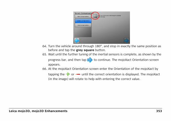
Leica mojo3D, mojo3D Enhancements 353
64. Turn the vehicle around through 180°, and stop in exactly the same position as before and tap the grey square button.
65. Wait until the further tuning of the inertial sensors is complete, as shown by the
progress bar, and then tap to continue. The mojoXact Orientation screen appears.
66. At the mojoXact Orientation screen enter the Orientation of the mojoXact by
tapping the or until the correct orientation is displayed. The mojoXact (in the image) will rotate to help with entering the correct value.

354Leica mojo3D, mojo3D Enhancements
Tap to continue and the Select Steering Kit screen appears.
67. Select the steer kit attached to the mojoXact by tapping the steer kit name in
the list. Tap or to reveal more options in the list.
68. Tap to continue.
Depending on the steer kit selected, The Select the model and make screen or the Steering Kit Status screen appears.
69. If the Select the model and make screen appears, select the model and make
appropriate for your steer kit by tapping on their names in the list. Tap to continue and the Steering Kit Status screen appears.
70. When both CAN Bus Connected and Steering Kit Active indicators on the Steering
Kit Status screen have a green tick icon, tap to continue.

Leica mojo3D, mojo3D Enhancements 355
71. The Configure Steering Kit screen appears. If the mojo3D system thinks that the steering controller is not configured, the Configure Steering Kit screen appears with only the Start button visible, giving the operator the only option to write the configuration to the steering controller.
If the mojo3D system thinks that the steering controller is configured, then the Configure Steering Kit screen appears with the Skip button selected. The Skip operation leaves the steering controller’s configuration untouched. If the oper-ator believes that the configuration has changed and needs to be written to the steering controller, then at this screen they can select Send Configuration. Caution must be exercised before tapping the Start button, to ensure that the steering controller does not contain any configuration that is needed, as the Send Configuration operation will overwrite any existing configuration in the steering controller with factory default settings.
If you are certain that the steering controller needs to have configuration written to it, then select the Send Configuration button and then tap the Start button.
If you are unsure about writing configuration to the steering controller, or you know that the steering controller is configured, select the Skip button.
Tap to continue.

356Leica mojo3D, mojo3D Enhancements
72. Depending on the steer kit selected, the Enable Stationary Engage screen may
appear. Configure its fields accordingly and tap to continue. The Steering Adjustment or the NMEA Configuration screen appears.
73. Depending on the steer kit selected, the Steering Adjustment screen may appear.
Follow the instructions on the screen to adjust the steering. Tap to continue and the NMEA Configuration screen appears.
74. If NMEA output is not required tap to complete the initial setup.
If NMEA output is required, follow the detailed information in "11 NMEA Output".
75. The mojoXact now needs to restart, so tap the Restart Now button and tap to continue.
The mojo3D will display an error message on completion of connection if the mojoXact/mojoXact Plus has not restarted completely.
To finalise the mojo3D to mojoXact connection, carry out the following steps:76. Test the steering function, according to "Testing the auto-steer function, step-
by-step", see "5.4 Testing Auto-Steer".77. Check the tuning, according to "5.2.1 Tuning Procedure".

Leica mojo3D, mojo3D Enhancements 357
Changing software configuration, step-by-step
It is possible to revisit the setup of the mojoXact/mojoXact Plus or attach a mojoXact/mojoXact Plus after the initial setup of the mojo3D. The steps below cover both of these scenarios.
To configure software for the mojo3D to mojoXact connection, carry out the following steps on the mojo3D:1. On the main navigation screen, tap the Settings button.
2. On the flyout menu, tap the Attached device button.
3. Tap the mojoXact button to continue.

358Leica mojo3D, mojo3D Enhancements
4. Select the necessary correction type from the list.
This will depend on the particular installation and the method chosen for GPS corrections, for example Base Station via internal radio.
5. Additional configuration information will need to be selected for most Correction
Source options. After setting this information tap to continue. 6. The screen will display the correction data being received and also the strength
of the correction signal. Tap to continue.
If GL1DETM Only was selected this screen will not be displayed.7. If a correction source other than GL1DETM Only was selected, the Enable GL1DE
Fallback screen appears. At this screen the operator can choose to have the system use the GL1DETM correction source in the event that their chosen correc-tion source fails. To select this option, tap the Enable GL1DETM Fallback box so it turns green.

Leica mojo3D, mojo3D Enhancements 359
• GL1DETM Fallback Time Limit is the time in minutes that the system will use the GL1DETM correction source. If the originally configured correction source has not come back online in this time period, then auto-steer is disabled.
• Drift Limit - if the originally configured correction source comes back online and the drift from the wayline is less than this value (in metres) then auto-steer remains enabled. However, if the drift from the wayline is greater than this value, then auto-steer is disabled.
Select or deselect Enable GL1DETM Fallback and tap the button. The Antenna Separation/Vehible Height/Red Antenna Offset screen appears.
8. Measure the distance shown by the image, then tap the measurement value field under the relevant image.
9. Use the on–screen number pad to enter the exact measurements. Tap on the number pad when finished.

360Leica mojo3D, mojo3D Enhancements
10. Tap to continue.
11. Tap to continue to the terrain compensation.
If this is not the first time a terrain compensation has been performed thenthere are three options to choose from:
• New Compensation: clears all previous compensation data, use when the hardware has been reinstalled or moved.
• Update Compensation: improves compensation performance, use only when hardware has not been re-installed or moved.
• Skip Compensation: skips the step and does not change the stored compen-sation data.
12. To perform a terrain compensation drive to a flat, level area and stop. Tap the square grey button beside the instruction when the vehicle is stationary.
13. Turn the vehicle around through 180°, and stop in exactly the same position as before and tap the grey square button.

Leica mojo3D, mojo3D Enhancements 361
14. Wait until the further tuning of the inertial sensors is complete, as shown by the
progress bar, and then tap to continue. 15. Enter the Orientation of the
mojoXact by tapping the or until the correct orientation is displayed. The mojoXact will rotate to help with entering the correct value.
16. When completed, tap to continue.17. Select the steer kit attached to the mojoXact by tapping the steer kit name in
the list. Tap or to reveal more options in the list.
18. Tap to continue.
Depending on the steer kit selected, The Select the model and make screen or the Steering Kit Status screen appears.
19. If the Select the model and make screen appears, select the model and make
appropriate for your steer kit by tapping on their names in the list. Tap to continue and the Steering Kit Status screen appears.

362Leica mojo3D, mojo3D Enhancements
20. When both CAN Bus Connected and Steering Kit Active indicators have a green
tick icon, tap to continue.21. The Configure Steering Kit screen appears.
If the mojo3D system thinks that the steering controller is not configured, the Configure Steering Kit screen appears with only the Start button visible, giving the operator the only option to write the configuration to the steering controller.
If the mojo3D system thinks that the steering controller is configured, then the Configure Steering Kit screen appears with the Skip button selected. The Skip operation leaves the steering controller’s configuration untouched. If the oper-ator believes that the configuration has changed and needs to be written to the steering controller, then at this screen they can select Send Configuration. Caution must be exercised before tapping the Start button, to ensure that the steering controller does not contain any configuration that is needed, as the Send Configuration operation will overwrite any existing configuration in the steering controller with factory default settings.
If you are certain that the steering controller needs to have configuration written to it, then select the Send Configuration button and then tap the Start button.

Leica mojo3D, mojo3D Enhancements 363
Final setup opera-tions, step-by-step
To finalise the mojo3D to mojoXact connection, carry out the following steps:1. Test the steering function, according to "Testing the auto-steer function, step-
by-step" see "5.4 Testing Auto-Steer".2. Check the tuning, according to "5.2.1 Tuning Procedure".
If you are unsure about writing configuration to the steering controller, or you know that the steering controller is configured, select the Skip button.
Tap to continue.22. Depending on the steer kit selected, the Enable Stationary Engage screen may
appear. Configure its fields accordingly and tap to continue.23. Depending on the steer kit selected, the Steering Adjustment screen may appear.
Follow the instructions on the screen to adjust the steering. Tap to continue.
24. Tap the Restart Now button and tap to continue.
25. Wait for the mojoXact to complete the restart, then tap to continue.
The mojo3D will display an error message on completion of connection if the mojoXact/mojoXact Plus has not restarted completely.

364Leica mojo3D, mojo3D Enhancements
A.5 Redeeming a System Option Voucher
Benefits Software options for the mojo3D are available as a voucher. This reduces the complexity at time of ordering if the customer information or serial numbers are not available.
General informa-tion
Software options provided on the mojo3D can be enabled by purchasing a voucher. Enable the feature by entering the voucher on http://www.virtualwrench.com/redeem along with the serial number of the device. A device specific code will be generated which can be entered onto the mojo3D to unlock the feature.
Redeem voucher To redeem a system option voucher, carry out the following steps:1. Record the device serial number
which can be found on the back on the mojo3D.
The serial number is the six digit article number with a dot followed by the serial. For example: 777533.000001
Art: 777533 Made in Singapore
S/N: 000001 Manuf.: 1210
mojo3D HSDPA Unit
GeoPRO_005
Leica mojo3D, mojo3D Enhancements 365
2. Visit http://www.virtualwrench.com/redeem and follow the instructions on screen.
3. On successful completion a feature unlock code will be provided. This unlock code is unique to the device with the serial number entered.
Connect the mojo3D to Virtual Wrench™ to automatically download the unlock code and enable the feature.OREnter the unlock code directly onto the mojo3D to manually enable the feature.

366Leica mojo3D, Formatting USB Flash Drives
Appendix B Formatting USB Flash DrivesDescription • USB Flash Drives are used to import/export data.
• USB Flash Drives are used for upgrading software.• USB Flash Drives are also used for data logging.• Drives must be formatted using the FAT file system.
Limitations The mojo3D require USB drives to be correctly formatted in order for it to operate correctly. Not all USB drives operate successfully with the mojo3D - please test and verify that the chosen USB drive operates as expected before using it.
Required items • USB Flash Drive / Memory Stick
• A computer running Microsoft WindowsTM (98, XP or later)• Available USB port on the computer

Leica mojo3D, Formatting USB Flash Drives 367
Procedure The USB Flash Drive is inserted into the computer. A window may be displayed asking what action to perform on the USB stick. Select Open folder to view files.
A window should then open showing the current contents of the USB Flash Drive.

368Leica mojo3D, Formatting USB Flash Drives
Navigate to Computer to show a list of all drives in the computer.
Right-click the drive icon for the USB stick to reveal the Format menu option.

Leica mojo3D, Formatting USB Flash Drives 369
Select FAT (File Allocation Table) from the File system box, then click Start.
A window will then be displayed asking you to confirm if you want to format the USB Flash drive. Click the OK button.

370Leica mojo3D, Formatting USB Flash Drives
The computer will then format the USB Flash Drive. The green progress bar will move from left to right.
A window will then be displayed indicating that the formatting of the USB Flash Drive is complete. Left-click the OK button.
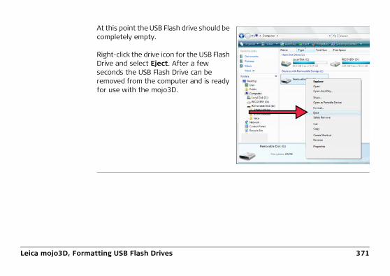
Leica mojo3D, Formatting USB Flash Drives 371
At this point the USB Flash drive should be completely empty.
Right-click the drive icon for the USB Flash Drive and select Eject. After a few seconds the USB Flash Drive can be removed from the computer and is ready for use with the mojo3D.

372Leica mojo3D, GNU General Public License
Appendix C GNU General Public Licensemojo3D software This product contains some software covered by the GPL V2 license and this state-
ment hereby constitutes an offer, valid for at least three years, to give any third party, for a charge of physically performing source distribution, a complete machine-readable copy of the corresponding source code. For detailed license terms and addi-tional information look at http://www.virtualwrench.com/gpl.

Leica mojo3D, GNU General Public License 373
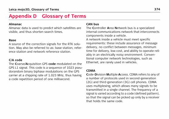
374Leica mojo3D, Glossary of Terms
Appendix D Glossary of TermsAlmanacAlmanac data is used to predict which satellites are visible, and thus shorten search times.
BaseA source of the correction signals for the RTK solu-tion. May also be referred to as: base station, refer-ence station and network reference station.
C/A codeThe Coarse/Acquisition GPS code modulated on the GPS L1 signal. This code is a sequence of 1023 pseu-dorandom binary biphase modulations on the GPS carrier at a chipping rate of 1.023 MHz, thus having a code repetition period of one millisecond.
CAN busThe Controller Area Network bus is a specialized internal communications network that interconnects components inside a vehicle. A network inside a vehicle must meet specific requirements: these include assurance of message delivery, no conflict between messages, minimum time for delivery, low cost, and ability to operate reli-ably in an electrically noisy environment. Conven-tional computer network technologies, such as Ethernet, are rarely used in vehicles.
CDMACode-Division Multiple Access. CDMA refers to any of a number of protocols used in second-generation (2G) and third-generation (3G) cell phones. CDMA uses multiplexing, which allows many signals to be transmitted in a single channel. The frequency of a signal is varied according to a code (defined pattern), so that the signal can be picked up only by a receiver that holds the same code.

Leica mojo3D, Glossary of Terms 375
CMRCompact Measurement Record. This is an RTK correction protocol.
DGPSDifferential Global Positioning Svstem, commonly used as a term to describe a GPS position corrected by a base station to remove some of the common position errors.
EDGEEnhanced Data rates for GSM Evolution. The EDGE protocol allows improved data transmission rates, as an extension of standard GSM. EDGE is a third-gener-ation (3G) technology.
EphemerisA list of positions or locations of a celestial object as a function of time.
GPSGPS is the short form of NAVSTAR GPS, which stands for NAVigation System with Time And Ranging Global Positioning System.
HSDPAHigh-Speed Downlink Packet Access. HSDPA is a protocol for cell phone data transmission. It is referred to as a 3.5G technology (G stands for Gener-ation). The HSDPA protocol provides download speeds on a cell phone that are equivalent to ADSL (Asymmetric Digital Subscriber Line) downloads on a landline. HSDPA evolved from, and is an improvement on, the W-CDMA protocol (a 3G protocol).
LatitudeThe angle between the ellipsoidal normal and the equatorial plane. Latitude is zero on the equator and 90° at the poles.
LongitudeLongitude is the angle between the meridian ellipse which passes through Greenwich and the meridian ellipse containing the point in question. Thus, longi-

376Leica mojo3D, Glossary of Terms
tude is 0° at Greenwich and is measured either east-ward through 360° or eastward 180° and westward 180°.
NMEANational Marine Electronics Association.
NMEA 0183NMEA 0183 is a combined electrical and data specifi-cation for communication between marine electronic devices such as echo sounder, sonars, anemometer (wind speed and direction), gyrocompass, autopilot, GPS receivers and many other types of instruments.
NTripNetworked Transport of RTCM via Internet Protocol.
Post processingThe process of computing positions in non-real-time, using data previously collected by GPS receivers.
RMSRoot Mean Squared, the root mean square is known as the quadratic mean and is a statistical measure of the magnitude of a varying quantity.
RTCMRadio Technical Commission for Maritime Services. RTCM3 is an RTK correction protocol.
RTKReal Time Kinematic. A term used to describe the procedure of resolving the phase ambiguity at the GPS receiver, so that the need for post-processing is removed.
SBASSatellite Based Augmentation System. SBAS comprises a number of ground stations at surveyed points. The ground stations take measurements of GPS satellites, their signals, and environmental factors that may affect the signals received by users, and create adjustment messages to send to one or more satellites for broadcast to users.

Leica mojo3D, Glossary of Terms 377

Total Quality Management: Our commitment to total customer satisfaction.
Leica Geosystems AG, Heerbrugg, Switzerland, has been certified as being equipped with a quality system which meets the International Standards of Quality Management and Quality Systems (ISO standard 9001) and Environmental Management Systems (ISO standard 14001).
Ask your local Leica Geosystems dealer for more information about our TQM program.
7775
38-3
.0.0
en O
rigin
al t
ext
Prin
ted
in S
witz
erla
nd ©
201
3 Le
ica
Geo
syst
ems
AG, H
eerb
rugg
, Sw
itzer
land
Leica Geosystems AGHeinrich-Wild-StrasseCH-9435 HeerbruggSwitzerlandPhone +41 71 727 31 31www.leica-geosystems.com