Embed Size (px)
Citation preview
X
X
X
X
X
X
X
X
X
X
X
X
X
X
X
X
X X
X
X
X
X
X
X
X
X
X
X
X
X
X
X X X
X
X
X
X
X
X
X
X
X
X
&
&&
&&
&&
&&
&
&&
&&
&& &&
&&&&&
&
&&&&&&&&&&&&&&&&
&&&
&
)
)
)
)
)
&
&
&
&
&
&
&
&
&
&
&
&
&
E
&
&
&
&
&
&
&
&
&
&
&
&
&
&
&&
&
&
&
&
&
&
&
&
&
&
&
&
&
&
&
&
&
&
&
&
&
&
&
&
&
&
&
&
&
&
&
&
&
E
&
&
&
&
&
&
&
&
&
&
&
&
&
&
&
&
&
&
&
&
&
&
&
&
&
&
&
&
&
&
&
&
&
&
&
&
&
&
&
&
&
&
&
&
&
&
&
&
&
&
&
&
&
&
&
&
&
&
&
&
&
&
&
&
&
&
&
&
&
&
&
&
&
&
&
&
&
&
&
&
&
&
&
&
&
&
&
&
&
&
&
&
&
&
&
&
&
&
&
&
&
&
&
&
&
&
&
&
&
&
&
&
&
&
&
&
&
&
&
&
&
&
&
&
&
&
&
&
&
&
&
&
&
&
&
&
&
&
&
&
&
&
&
&
&
&
&
&
&
&
&
&
&
&
&
&
&
&
&
&
&
&
&
&
&
&
&
&
&
&
&
&
&
&
&
&
&
&
&
&
&
&
&
&
&
&
&
&
&
&
&
&
&
&
&
&
&
&
&
&
&
&
&
&
&
&
&
&
&
&
&
&
&
&
&
&
&
&
&
&
&
&
&
&
&
&
&
&
&
&
&
&
&
&
&
&
&
&
&
&
&
&
&
&
&
&
&
&&
&
&
&
&
&
&
&
&
&
&
&
&
&
&
&
&
&
&
&
&
&
&
&
&
&
&
&
&
&
&
&
&
&
&
&
&
&
&
&
&
&
&
&
&
&
&
&
&
&&
&
&
&
&
&
&
&
&
&
&
&
&
&
&
&
&
&
&
&
&
&
&
&
&
&
&
&
&
&
&
&
&
&
&
&
&
&
&
&
&
&
&
&
&
&
&
&&
&
&
&
&
&
&
&
&
&
&
&
&
&
&
&
&
&
&
&
&
&
&
&
&
&
&
&
&
&
&
&
&
&
&
&
&
&
&
&
&
&
&
&
&
&
&
&
&
&
&
&
&
&
&
&
&
&
&
&
&
&
&
&
&
&
&
&
&
&
&
&
&
&
&
&
&
&
&
&
&
&
&
&
&
&
&
&
&
&
&
&
&
&
&
&
&
&
&
&
&
&
&
&
&
&
&
&
&
&
&
&
&
&
&
&
&
&
&
&
&
&
&
&
&
&
&
&
&
&
&
&
&
&
&
&
&
&
&
&
&
&
&
&
E
&
&
&
&
&
&
&
&
&
&
&
&
&
&
&
&
&
&
&&
&
&
&
E
&
&
&
&
&
&
&
&
&
&
&
&
&
&
&
&
&
&
&
&
&
&
&
&
&
&
&
&
&
&
&
&
&
&
&
&
&
&
&
&
&
&
&
&
&
&
&
&
&
&
&
&
&
&&
&
&
&
&
&
&
&
&
&
&
&
&
&
&
&
&
&
&
&
&
&
&&
&
&
&
&
&
&
&
&
&
&
&
&&
&
&
&
&
&
&
&&
&
&
&
&
&
&
&
&
&
&
&
&
&
&
&
&
&
&
&
&
&
&
&
&
&
&
&
&
&
&
&&&
&&
&
&
&
&
&
&
&
&
&
&
&
&
&
&&
&
&
&
&
&
&
&
&
&
&
&
&
&
&
&
&
&
&
&
&
&
&
&
&
&
&
&
&
&
&
&
&
&
&
&
&
&
&
&
&
&
&
&
&
&
&
&
&
&
&
&
&
&
&
&
&
&
&
&
&
&
&
&
&
&
&
&
&
&
&
&
&
&
&
&
&
&
&
&
&
&
&
&
&
&
&
&
&
&
&
&
&
&
&
&
&
&
&
&
&
&
&
&
&
&
&
&
&
&
&
&
&
&
&
&
&
&
&
&
&
&
&
&
&
&
&
&
&
&
&
&
&&
&
&
&
&
&
&
&
&
&
&
&
&
&
&
&
&
&
&
&
&
&
&
&
&
&
&
&
&
&
&
E
&
&
&
&
&
&
&
&
&
&
&
& &&
&
&
&
&
&
&
&
&
&
&
&
&
&
&
&
&
&
&
&
&
&
&
&
&
&
&
&
&
&
&
&
&
&
&
&
&
&
&
&
&
&
&
&
&
&
&
&&
&
&
&
&
&
&
&
&
&
&
&
&
&
&
&
&
&
&
&
&
&
&
&
&&
&
&
&
&
&
&
&
&&
&
&
&
&
&
&
&
&
&
&
&
&
&
&
&
&
&
&
&
&
&
&
&
&
&
&
&
&
&
&
&
&
&
&
&
&
&
&
&
&
&
&
&
&
&
&
&
&
&
&
&
&
&
&
&
&
&
&
&
&
&
&
&
&
&
E
&
&
&
&
&
&
&
&
&
&
&
&
&
&
&
&
&
&
&
&
&
&
&
&
&
&&&
&
&
&
&
&
&
&
&
&
&
&
&
&
&
&
&
&
&
&
&
&
&
&
&
&
&
&
&
&
&
&
&
&
&
&
&
&
&
&
&&
&
&
&
&
&
&
&
&
&
&
&
&
&
&
&
&
&&
&
&
&
&
&
&
&
&
&
&
&
&
&
&
&
&
&
&
&
&
&
&
&
&
&
&
&
&
&
&
&
&
&
&
&
&
&
&
&
&
&
&
&
&
&
&
&
&
&
&
&
&
&
&
&
&
&
&
&
&
&
&
&
&
&
&
&
&
&
&
&
&
&
&
&
&
&
&
&
&
&
&
&
&
&
E
&
&
&
&&
&
&
&
&
&
&
&
&
&
&
&
&
&
&
&
&
&
&
&
&
&
&
&
&
&
&
&
&
&
&
&
&
&
&
&
&
&
&
&
&
&
&
&
&
&
&
&
&
&
&
&
&
&
&
&
&
&
&
&
&
&
&
&
&
&
&
&
&
&
&
E
&
&
&
&
&
&
&
&
&
&
&
&&
&
E
&
&
&
&
&
&
&
&
&
&
&
&
&
&
&
&
E
&
&
&
&
&
&
&
&
&
&
&
&
&
&
&
&
&
&
&
&
&
&
&
&
&
&
&
&
&
&
&
&
&
&
&
&
&
&
&
&
&&
&
&
&
&
&
&
&
&
&
&
&
&
&
&
&
&
&
&
&&
&
&
&
&
&
&
&
&
&
&
&
&
&
&
&
&
&
&
&
&
&
&
&
&
&
&
&
&
&
&
&
&
&
&
&
&
&
&
&
&
&
&
&
&
&
&
&
&
&
&&
&
&
&
&
&
&&
&
&
&
&
&
&
&
&
&
&
&
&
&
&
&
&
&
&
&
&
&
&
&
&
&
&
&
&
&&
&
&
&
&
&
&
&
&
&
&
&
&
&
&
&
&
&
&
&
&
&
&
&
&
&
&
&
&
&
&
&
&
&
&
&
&
&
&
&
&
&
&
&
&
&
&
&
&
&
&
&
&
&
&
&
&
&
&
&
&
&
&
&
&
&
&
&
&
&
&
&
&
&
&
&
&
&
&
&
&
&
&
&
&
&
&
&
&
&
&
&
&
&
&
&
&
&
&
&
&
&
&
&
&
&
&
&
&&
&
&
& &&
&
&
&
&
& &
&
&
&
&
&
&
&
&
&
&
&
&
&
&&
&&
&
&&
&
&
&
&
&
&
&
&
&
&&
&
&
&
&
&
&
&
&
&
&
&
&
&
&
&
&
&
&
&
&
&
&
&
&
&
&
&
&
&
&
&
&
&
&
&
&
&
&
&
&
&
&
&
&
&
&
&
&
&
&
&
&
&
&
&
&
&
&
&
&
&
&
&
&
&
&
&
&
&
&
&
&
&
&
&
&
&
&
&
&
&
&
&
&
&
&
&
&
&
&
&
&
&
E
&
&
&
&
&
&
&
&
&
&
&
&
&
&
&
&
&
&
&&
&
&
&
&
&
&
&
&
&
&
&
&
&
&
&
&
&
&
&
&
&
&
&
&
&
&
&
&
&
&
&
&
&
&
&
&
&
&
&
&
&
&
&
&
& &
&
&
&
&
&&
&
&
&
&
&
&
&
&
&
&
&
&
&
&
&
&
&
&
&
&
&
&
&
&
&
&
&
&
&
&
&
&
&
&
&
&
&
&
&
&
&
&
&
&
&
&
&
&
&
&
&
&
&
&
&
&
&
&
&
&
&
&
&
&
&
&
&
&
&
&
&
&
&
&
&
&
&
&
&
&
&
&
&
&
&
&
&
BoonLake
Lake
Lake
Lake
Lake
Hodgson
Allie
Phare
Preston
1
1 1 1 1 1
111
11111
1 1 1 1 1 1 1 6
31 3636
36
36 36
363636 313131
31 31
666
6 6
6 66 6
666
6
6
6 666 6
6
31313131
31 31 31 31
36 36 36 36
36 36 36 36
6
31
1 1
6 6
6666
11
1111
36 36 36
36363636
3131
3131
31
3131
1
1
36
36
36 3631
CAIRO
WELLINGTONBANDON
CAMP
BIRCH COOLEYBEAVER FALLS
MARTINSBURGPALMYRA
MELVILLE HECTOR PRESTON LAKE
BOON LAKEBROOKFIELDOSCEOLAKINGMAN
BIRD ISLAND
WANG
ERICSON CROOKS WINFIELD
HAWK CREEK EMMET TROYSACRED HEART
FLORA HENRYVILLE NORFOLK
44° 45'
94° 45' 94° 30'
94° 30'
44° 45'
44° 30'44° 30'
94° 45'
95° 00'
95° 00'
95° 15'
95° 15'
)4
)4
)4
)19)19
)19
71
71
71
212 212
212
212
T. 116 N.
T. 115 N.
T. 114 N.
T. 113 N.
T. 112 N.
T. 116 N.
T. 115 N.
T. 114 N.
T. 113 N.
T. 112 N.
R. 31 W.R. 32 W.R. 33 W.R. 34 W.R. 35 W.R. 36 W.R. 37 W.R. 38 W.
R. 38 W.
R. 37 W.
R. 36 W.
R. 35 W.
R. 34 W.
R. 33 W.
R. 32 W.
REDWOOD COUNTY
KANDIYOHI COUNTY
SIBLEY COUNTY
SIBL
EY C
OU
NTY
NICOLLET COUNTY
YELLOW MEDICINE COUNTY
BROWN COUNTY
YELLOW MEDICINECOUNTY
CHIPPEWA COUNTY KANDIYOHI COUNTY MEEKER COUNTY MEEKER COUNTY
MC
LEO
D C
OU
NTY
MC
LEO
D C
OU
NTY
NICOLLETCOUNTY
CH
IPPE
WA
CO
UN
TY
Timm
s
Creek
Minnesota
River
Fort
RidgelyCreek
Creek
Threemile
CreekSmith
Beav
er
Cree
k
Creek
Mid
dle
Creek
Sacred
Heart
CreekBeaver
ForkEast
West
Fork
Beaver
Creek
Buffalo
Buffalo
Buffalo
Creek
Creek
East
BeaverFork
CreekBeaver
Fork
West
Creek
SacredHeart
Creek
Chetam
ba
Creek
Creek
Chetamba
Creek
Hawk
Hawk
Spring
REDWOODCOUNTY
Minnesota
River
Creek
Creek
Creek
Buffalo Lake
Hector
Bird IslandOlivia
Danube
RenvilleSacred Heart
FairfaxFranklin
Morton310
320
330
250
340
330
320
330
320
330
330
330
330
310
340
340
330
320
300
330
320
320
340
260
320
320
340
320
260
310
330
330
330
330
330
330
320
330
330
320
320
320
320
310
330
320
340
320
340
340
280
330
330
340
320
340
320
330
330
330
320
310
320
320
270
320
330
320
320
330
310
310
330
320
330
330
340
260
330
310
320
330
320
340
330
330
320
330
340
330
310
340
330
330
330
330
340
330
330
320
330
330
270
310
330
340
340
310
320
330
330
340
330
320
320
250
330
340
340
330
340
330
340
320
330
320
340
330
330
330
270
320
330
330
330
310
310
300
340
330
330
340
320
320
320
320
330
330
340
330
330
320
340
330
340 330
320
330
330
320
320
320
330
320
310
320
340
330
330
330
340
320
320
330
310
330
330
330
320
320
270
310
310
330
310
330
300
320
330
340
330
320
320
330
330
330
340
330
330
330
320
320
310
320
320
310
330
330
330
320
330
330
340
340
340 330
340
310
330
330
320
320
340
340
330
330
330
330
320
310
330
330
330
340
330
270
270
330
320
320
330
330
320
320
340
320
260
320
330
330
330
320
320
330
330
340
310
330
330
330
260
340
250
340
330
280
340
330
310
330
330
300
290
270
310
270
310
320
310
310
310
260
260
300
280
310300
300
290
#
#
#
#
#
#
#
#
#
#
#
#
#
#
#
#
#
#
#
#
#
#
#
#
#
#
#
#
#
##
#
*
#
#
#
#
#
*
#
#
#
#
#
#
#
#
##
#
***
*
#
#
#
#
#
#
#
#
#
#
#
#
#
##
#
#
#
#
#
#
#
#
#
#
#####
##
#
#
#
##
#
#
#
#
#
#*
#
*
#
#
#
##
#
#
#
#
#
#
k
k
k
k
k
k
k
k
k
k
k
kk
k
k
D
DD
D
D
D
D
D
D
D
D
DD
D
D
D
D
D
D
D
D
D
D
D
D
D
D
D
D
D
D
D
D
D
D
D
D
D
D
D
D
D
D D
D
D
D
D
D
D
D
(
(
(
(
(
(
(
(
(
(
(
(
(
(
(
(
(
(
(
(
#
#
*##
#
###
##
#
##
#
##
*
#
##
#####
*
**#
##
#
#
*
*
#
#*#
*
*
*
#
###
#
#
##
#
#*
#
###
##
#
##
##
##
#
#
#
)
)
)
)
&
&
&
&
&
&
&&
&
&
&
&
&
&
&
&
&
&
&
&
&
&&
&&
&
&
& & &
&&
&&&
& & &
&&&
& & & &&
&&&&&
&
&
& &
&
&
& & & & &
&
& & & &
&&&&&&&&&&
& & & & & & & & &
&&&&&&&
&
&&&&
& & &&
& &
& & &
&
&&
&
&&&
& & & & &
&&&&&&&
&
&
&
& & & & & &
&
&&&&&&&
&
&
&
&
&
&
&
&&
&
&
&
&
&
&
&
&
&
& &
&&
& &&&&&
&
&
&
&
&
&
&
&
&
&
&&&
&&
& & & & & &
&
&
&&&&&&&
&
&&&
&
&
& & & & & &
&&&&&
&&
&
&
& & & & & &
&
& & & &
& &
&
&
&
&&&
&
&&
&&&
&&&
&&&
&&
&
&&
&&
&&
&
&
&&
&&&
&&&
&&&&
&&&
&
&&&&
&
&
&
&&
&
&&&
&&&
&&&
&&&
&&&&
&&&&&&
&&&&&&
&&&&&
&&&&&&&
&&&&&&
&&&&&&
&&
&&
&&
&&
&&
&
&&&
&&
&
&&
&&&
&&
&
&
&
&
&
&
&
&
&&
&
&
&&&
&&&
&&&&
&&&
&&
&
&&&
&
&
&
&&
&
&
&
&&&
&
&&
&&&
&&&&
&&&&
&&&
&&&
&&&&&&&&
&
&&&
&&&
&&
&
&
&&
&
&
&&
&&
&&
&&
&&&
&&&
&&&
&&
&&&&&
&
&&&&&
&& &&&&
&&&&&&
&&&&&&
&&&
&
&&
&
&
&
&
&
&&
&&&
&&&
&
&
&
&
&
&
&
&
& &
&&
&
&&&
&&
&&&
&
&&&&
&
&
&
&
&
&
&
&
&
&
&
&
&
&
&& &&
Every reasonable effort has been made to ensure the accuracy of the factual data on which this map interpretation is based; however, the Minnesota Geological Survey does not warrant or guarantee that there are no errors. Users may wish to verify critical information; sources include both the references listed here and information on file at the offices of the Minnesota Geological Survey in St. Paul. In addition, effort has been made to ensure that the interpretation conforms to sound geologic and cartographic principles. No claim is made that the interpretation shown is rigorously correct, however, and it should not be used to guide engineering-scale decisions without site-specific verification.
MINNESOTA GEOLOGICAL SURVEYHarvey Thorleifson, Director
DATA-BASE MAP
By
Emily J. Bauer
2013
Digital base modified from the Minnesota Department of Transportation BaseMap data; digital base annotation by the Minnesota Geological Survey.
Elevation contours were derived from the U.S. Geological Survey 30-meter Digital Elevation Model (DEM) by the Minnesota Geological Survey.
Universal Transverse Mercator Projection, grid zone 151983 North American Datum
coNToUr INTervAl 10 MeTerS
1 0 1 2 3 4 5 MILES
8 KILOMETERS
SCALE 1:100 000
1 0 1 2 3 4 5 6 7
locATIoN DIAGrAM
COUNTY ATLAS SERIESATLAS C-28, PART A
Renville County Plate 1—Data Base
GEOLOGIC ATLAS OF RENVILLE COUNTY, MINNESOTA
Prepared and Published with the Support of
THE RENVILLE COUNTY BOARD OF COMMISSIONERS, AND THE MINNESOTA DEPARTMENT OF NATURAL RESOURCES, DIVISION OF WATERS
GIS compilation by e.J. Baueredited by lori robinson
©2013 by the regents of the University of Minnesota
The University of Minnesota is an equal opportunity educator and employer
Unique Well Number County Renville
riDegnaRemaN lleW Township Section Subsection Depth Drilled Depth Completed Lic/Reg. No.Date Completed
QuadQuad Id
BHS-3-B-1 32 W 7 CDAAAB114 400 400ft ft MGS1982/01/21
Elevation 1100.00 ft. Screen/Open HoleMethod 7.5 minute topographic Aquifer Depth to Bedrock 310 ft.
Field LocatedProgramUni No.Verified
Location MethodInput SourceInput Date
Universal Transverse Mercator(UTM) - NAD83 - Zone 15 - MetersUTM Northing (Y)UTM Easting (X)
361977 49501241990/01/01
Hector
1988/04/172009/09/03
Entry DateUpdate DateReceived Date
MINNESOTA DEPARTMENT OF HEALTHWELL AND BORING RECORD
MINNESOTA STATUTES CHAPTER 1031
Driller Name
SWL
236548
Information from owner
Minnesota Geological Survey
Geological Material MinorSecondaryDEPTH
PrimaryELEVATION LITHOLOGY
Hardness StratigraphyFrom To Thick From ToColor
Howard Hobbs MGS Geologic study 1:24k to 1:100kycnegAnoitaterpretnI cigoloeG Interpretation Method
94B
SANDY CLAYEY SILT SiltOrganic DepositsBROWN 2 Recent deposit-brown Soil2 1100 10980
F-C SAND, TRACE GRAVEL GravelBRN/GRY 26 sand +larger Sand24 1098 10742
SANDY SILTY CLAY/SANDY CLAYEY SI SandSiltGRAY 79 till w/calc.pebbles-gry Clay53 1074 102126
SANDY CLAYEY SILT, TRACE GRAVEL SandClayGRAY 220 till w/calc.pebbles-gry Silt141 1021 88079
SANDY CLAYEY SILT, TRACE GRAVEL SandClayBROWN 260 till w/calc.pebbles-brn Silt40 880 840220
SANDY SILTY CLAY, TRACE GRAVEL SandSiltGRAY 310 till w/calc.pebbles-gry Clay50 840 790260
GRN-GRY TO WHITE CLAYEY SAND VARIED 400 Cretaceous regolith Regolith90 790 700310
MORTON
MAYNA
RD
CLAR
A CI
TY
PRIN
SBUR
G
DANU
BE
BLOMKE
ST
LAKE
LILL
IAN
THORP
E
COSM
OS
CEDA
R MILL
S
HUTC
HINS
ON W
EST
OLIVIA
SE
CHUR
CHILL
LAKE
ALL
IE
HEAT
WOLE
STEW
ART
HECT
OR
MORTON
NE
MORTON
NW
BECH
YN
VICK
SBUR
G
DELH
I
FAIR
FAX
GIBBO
N
ST. G
EORG
E
MINNE
SOTA
FALL
S
SACR
ED H
EART
RENV
ILLE
OLIVIA
MORTON
SE
SLEE
PY E
YE N
W
BUFF
ALO LA
KE
LONE
TREE
LAKE
IVER
SON
LAKE
REDW
OOD FA
LLS
MORTON
NE
INDEX TO 7.5-MINUTE QUADRANGLES
INTRODUCTION
The public health and economic development of Renville County are directly dependent on the wise use and management of its land and water resources. Geologic and hydrologic information are essential before decisions are made that affect natural resources. Although the amount of geologic information required for making specific decisions can vary, the information will not be used if it is unavailable when needed, or if it is available only in a highly technical form, or scattered in many different maps and reports.
County atlases, prepared jointly by the Minnesota Geological Survey and the Minnesota Department of Natural Resources, Division of Waters, present detailed geologic and hydrologic information in an interpretive as well as descriptive form. Maps and texts either summarize basic geologic and hydrologic conditions at a county scale, or interpret these conditions in terms of the impacts of possible land- and water-use decisions. Site-specific information is also available at a greater level of technical detail than shown on the maps of this atlas. The data are too voluminous to present in the atlas, but have been incorporated into readily accessible files housed at the Minnesota Geological Survey.
Several sources commonly provide information about an area or an individual property, but they may use different classification schemes to describe the same geologic materials. As a result, discrepancies in interpreting the data may arise or the different sources may appear to contradict each other. For example, water-well drillers may describe glacial till as "clay," but engineering records will describe it as "clayey sand." Both descriptions are acceptable for their original purpose of describing the physical attributes of the material. "Clay," the term used by well drillers, defines the general inability of the till to yield ground water to a well. "Clayey sand," the term from the engineering record, defines the physical composition of the till relative to particle size and engineering properties. The geologist must take the analysis one step further and define the material in terms of how it formed rather than how it is to be used. In this example, till consists of an unsorted mixture of rock fragments ranging in size from clay to cobbles and boulders, and it is interpreted by the geologist as having been deposited directly by glacial ice. Understanding the process by which the material formed allows geologists to make predictions about what lies between and beyond data points.
All of the types of data described on this plate had to be interpreted by geologists or hydrogeologists before they were meaningful for mapping purposes. The 1:100,000 and 1:200,000 scales of the maps in this atlas were chosen because they can show the geologic and topical studies of the county while keeping the physical size of each plate to a manageable level. As a result, some detailed information that was gained by data interpretation and mapping cannot be shown on these maps or discussed in the texts.
Whether to use the atlas alone, or in combination with the data bases, depends on the amount of detail needed. Generally, data-base information must be used to evaluate site-specific conditions.
DATA-BASE MANAGEMENT
All of the data shown on the maps were plotted on 7.5-minute topographic quadrangle maps or highway alignment maps and assigned inventory numbers. Automated data bases and a few manual files were developed to provide easy access and rapid retrieval of these site-specific data. The data may be obtained from the Minnesota Geological Survey.
Computer storage and retrieval systems are better than manual files for manipulating large amounts of data because automated geologic data bases can be designed to interact with other computer files, such as land-use data. Such interaction permits more efficient assessment of cause-and-effect relationships concerning natural resources than is commonly possible with manual files.
RENVILLE COUNTY DATA BASES
Computerized files were developed for point-source data such as wells and borings in Renville County. They use Public Land Survey descriptions, Universal Transverse Mercator (UTM), and latitude-longitude coordinates as location criteria; thus, they are compatible with the natural-resource data bases housed at the Minnesota Land Management Information Center (LMIC). The computerized data bases developed for Renville County by the Minnesota Geological Survey are County Well Index (CWI) and Quaternary Samples Data Base (QBASE).
County Well Index (CWI)—Information from water-well records and exploration holes is entered into this statewide data base. Each well log is assigned a six-digit unique number and each exploration drill hole is assigned either a five- or six-digit unique number. These reference numbers are also used by state agencies and the Water Resources Division of the U.S. Geological Survey. Elevations, expressed in feet above sea level, were determined from topographic maps (see the index to 7.5-minute quadrangles) and are generally accurate to plus or minus five feet (1.5 meters). The street address of each well is also included wherever possible to provide data users with a well-location system that is compatible with local regulatory programs. Software at the Minnesota Geological Survey is used to display and tabulate many of the data elements contained on the original well log.
The County Well Index is currently stored in a data base that consists of nine related tables. These tables contain information such as well depths, well construction, addresses,
k
MAP SYMBOLS
Record of water-well construction (well driller's log)
Exploratory boring
Diamond drill core sample
Rotary-sonic core sample
Cutting sample
Borehole geophysical log
Soil boring
Giddings probe hole
Field site
Field site with textural analysis
Gravity reading
Passive seismic sounding
Bedrock outcrop
&
X
E
&
#
)
&
D
(
)
*
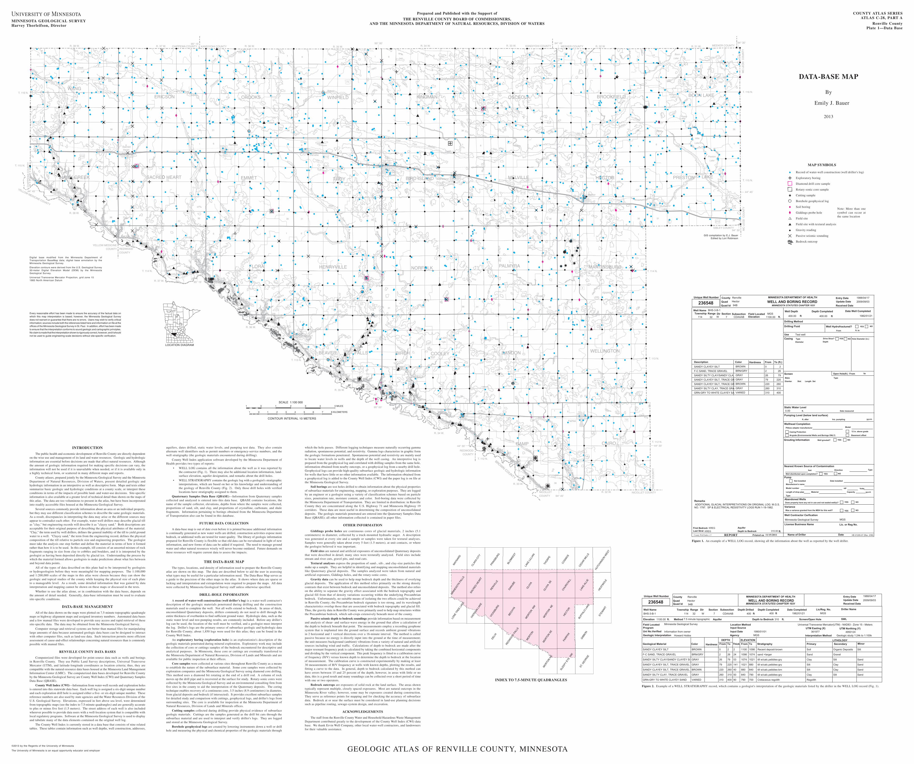
Figure 2. Example of a WELL STRATIGRAPHY record, which contains a geologist's interpretation of the geologic materials listed by the driller in the WELL LOG record (Fig. 1).
County
Well NameRange DirTownship Section Subsection
Well Depth Depth Completed Date Well Completed
Update DateRenville
BHS-3-B-1
32 W 7 CDAAAB114 400.00 400.00 1982/01/21ft ft
Make
Static Water Level
Open Hole(ft.) From
Last Strat
g.p.m.hrs. pumpting
Grouting Information
Capacity
Well disinfected upon completion?
Pump
Variance
Abandoned Wells
Screen
Nearest Known Source of Contamination
UseCasing Drive Shoe?
Well Contractor Cerfication
Quad
Depth to Bedrock
Pumping Level (below land surface)
Model
94B
1100.00
Test well
MGS
Pitless adapter manufacturer
ft.
Well grouted?
feet Direction Type
Printed on
Model number
Manufacture's name
REPORT
Type
Wellhead Completion
310.00
MINNESOTA DEPARTMENT OF HEALTH
MINNESOTA STATUTES CHAPTER 1031WELL AND BORING RECORD
Description From To (ft.)Color HardnessSANDY CLAYEY SILT BROWN 20
F-C SAND, TRACE GRAVEL BRN/GRY 262
SANDY SILTY CLAY/SANDY CLA GRAY 7926
SANDY CLAYEY SILT, TRACE GR GRAY 22079
SANDY CLAYEY SILT, TRACE GR BROWN 260220
SANDY SILTY CLAY, TRACE GRA GRAY 310260
GRN-GRY TO WHITE CLAYEY SA VARIED 400310
Remarks ADDITIONAL GLACIAL INTERPRETATIONS ON ORIGINAL LOG. M.G.S.NO. 1797. SP & ELECTRICAL RESISTIVITY LOGS RUN 1-19-1982.
Drilling Method
Drilling Fluid Well Hydrofractured? NO
From
YES
ft. to
HE-01205-07 (Rev. 2/99)Date
Lic. or Reg No.
Minnesota Geological Survey
Was a variance granted from the MDH for this well?
Does property have any not in use and not sealed well(s)?
11/15/2011
dellatsnI etaDdellatsnI toN
Type
Length of drop pipe
HP Volts
g.p.m
to
TypeDiameter
Hole Diameter (in.)YES NO
Elevation
At-grate (Environmental Wells and Borings ONLY)
Casing Protection 12 in. above grade
Basement offset
YES NO
YES NO
YES NO
YES NO
ft. after
Date measured
Material
Diamter Length SetSlot
0.00
Depth
1988/04/172009/09/03
Entry Date
Received Date
Unique Well Number
County Well Index v.5
Aquiferft.
First Bedrock KREGKREG
Field Locatedft.
Quad Id
MGS
236548 Hector
License Business Name
Name of Driller
Figure 1. An example of a WELL LOG record, showing all the information about the well as reported by the well driller.
aquifers, dates drilled, static water levels, and pumping test data. They also contain alternate well identifiers such as permit numbers or emergency-service numbers, and the well stratigraphy (the geologic materials encountered during drilling).
County Well Index application software developed by the Minnesota Department of Health provides two types of reports:
WELL LOG contains all the information about the well as it was reported by •the contractor (Fig. 1). There may also be additional location information, land-surface elevation, aquifer designation, and remarks about the drill holes.
WELL STRATIGRAPHY contains the geologic log with a geologist's stratigraphic •interpretations, which are based on her or his knowledge and understanding of the geology of Renville County (Fig. 2). Only those drill holes with verified locations have stratigraphy assigned to them.
Quaternary Samples Data Base (QBASE)—Information from Quaternary samples collected and analyzed is entered into this data base. QBASE contains locations, the name of the sample collector, elevations, depths from where the samples were collected, proportions of sand, silt, and clay, and proportions of crystalline, carbonate, and shale fragments. Information pertaining to borings obtained from the Minnesota Department of Transportation also can be found in this database.
FUTURE DATA COLLECTION
A data-base map is out of date even before it is printed because additional information is continually generated as new water wells are drilled, construction activities expose more bedrock, or additional wells are tested for water quality. The library of geologic information prepared for Renville County is flexible so that old data can be reevaluated in light of new information, and new forms of data can be added if required. The need to manage ground water and other natural resources wisely will never become outdated. Future demands on these resources will require current data to assess the impacts.
THE DATA-BASE MAP
The types, locations, and density of information used to prepare the Renville County atlas are shown on this map. The data are described below to aid the user in assessing what types may be useful for a particular information need. The Data-Base Map serves as a guide to the precision of the other maps in the atlas. It shows where data are sparse or lacking and interpretation and extrapolation were required to prepare the maps. All data were collected by Minnesota Geological Survey staff unless otherwise specified.
DRILL-HOLE INFORMATION
A record of water-well construction (well driller's log) is a water-well contractor's description of the geologic materials penetrated during drilling and the construction materials used to complete the well. Not all wells extend to bedrock. In areas of thick, unconsolidated Quaternary deposits, drillers commonly do not need to drill through the entire thickness of overburden to find sufficient ground water. Hydrologic data, such as the static water level and test-pumping results, are commonly included. Before any driller's log can be used, the location of the well must be verified, and a geologist must interpret the log. Driller's logs are the primary source of subsurface geologic and hydrologic data for Renville County; about 1,850 logs were used for this atlas; they can be found in the County Well Index.
An exploratory boring (exploration hole) is an explorationist's description of the geologic materials penetrated during mineral exploration. Exploratory work may include the collection of core or cuttings samples of the bed rock encountered for descriptive and analytical purposes. In Minnesota, these core or cuttings are eventually trans ferred to the Minnesota Department of Natural Resources, Division of Lands and Minerals and are available for public inspection at their offices.
Core samples were collected at various sites throughout Renville County as a means to establish the nature of the subsurface material. Some core samples were collected by exploration companies and the Minnesota Geological Survey using diamond core drilling. This method uses a diamond bit rotating at the end of a drill rod. A column of rock moves up the drill pipe and is recovered at the surface for study. Rotary-sonic cores were collected by the Minnesota Geological Survey and an environmental consulting firm from five sites in the county to aid the interpretation of the Quaternary deposits. The coring technique enables recovery of a continuous core, 3.5 inches (8.9 centimeters) in diameter, from glacial deposits and bedrock (if intersected). It provides excellent subsurface samples for detailed study and comparison with cuttings, geophysical logs, and driller's logs from surrounding sites. The core is available for inspection at the Minnesota Department of Natural Resources, Division of Lands and Minerals offices.
Cutting samples collected during drilling provide physical evidence of subsurface geologic materials. Cuttings are the samples generated as the drill bit cuts through the subsurface material and are used to interpret and verify driller's logs. They are logged and stored at the Minnesota Geological Survey.
Borehole geophysical logs are created by lowering instruments down a well or drill hole and measuring the physical and chemical properties of the geologic materials through
which the hole passes. Different logging techniques measure naturally occurring gamma radiation, spontaneous potential, and resistivity. Gamma logs characterize in graphic form the geologic formations penetrated. Spontaneous potential and resistivity are mainly used to locate water levels in wells and the depth of the well casing. An interpretive log is prepared from the geophysical log and correlated with drilling samples from the same hole, information obtained from nearby outcrops, or a geophysical log from a nearby drill hole. Geophysical logs can provide high-quality subsurface geologic and hydrologic information for wells that have little or no other information available. The information obtained from a geophysical log is added to the County Well Index (CWI) and the paper log is on file at the Minnesota Geological Survey.
Soil borings are test holes drilled to obtain information about the physical properties of subsurface materials for engineering, mapping, or exploration purposes. They are logged by an engineer or a geologist using a variety of classification schemes based on particle sizes, penetration rate, moisture content, and color. Soil-boring data were collected by the Minnesota Department of Transportation. They are limited in distribution: in Renville County they are concentrated along the U.S. Highway 71 and Minnesota Highway 19 corridors. These data are most useful in determining the composition of unconsolidated deposits. The geologic materials penetrated are entered into the Quaternary Samples Data Base (QBASE); all other information collected is contained in paper files.
OTHER INFORMATION
Giddings probe holes are continuous cores of glacial materials, 2 inches (5.1 centimeters) in diameter, collected by a truck-mounted hydraulic auger. A description was generated at every site and a sample or samples were taken for textural analyses. Samples were generally taken about every 5 feet (1.5 meters), at unit contacts, or where the geologist believed it was important.
Field sites are natural and artificial exposures of unconsolidated Quaternary deposits that were described in detail; many sites were texturally analyzed. Field sites include stream and river cuts, gravel pits, and road cuts.
Textural analyses express the proportion of sand-, silt-, and clay-size particles that make up a sample. They are helpful in identifying and mapping unconsolidated materials like Quaternary glacial deposits. The samples analyzed were taken from natural and artificial exposures, Giddings holes, and the rotary-sonic cores.
Gravity data can be used to help map bedrock depth and the thickness of overlying glacial deposits. The application of this method relies primarily on the strong density contrasts that exist between bedrock and unconsolidated deposits. The method also relies on the ability to separate the gravity effect associated with the bedrock topography and glacial fill from that of density variations occurring within the underlying Precambrian bedrock. Unfortunately, no suitable means of isolating the two effects could be achieved in Renville County; the Precambrian bedrock signature is too strong, and its wavelength characteristics overlap those that are associated with bedrock topography and glacial fill. Thus, the gravity data in Renville County were primarily used to help map structures within the Precambrian bedrock, which sub-crops extensively beneath most of the county.
Passive seismic depth to bedrock soundings provide information based on measurement and analysis of shear- and surface-wave energy in the ground that allow a calculation of the depth to bedrock beneath that point. The measurements employ a recording geophone system that is implanted into the ground surface and records ambient ground vibrations in 2 horizontal and 1 vertical directions over a 16-minute interval. The method is called passive because no energy is directly input into the ground at the time of measurement; the unit measures background (ambient) vibrations from a variety of natural and artificial sources including wind and traffic. Calculations of depth to bedrock are made after the major resonant frequency peak is calculated by taking the combined horizontal components and dividing by the vertical component. This peak frequency is fitted to a calibration curve of frequency (H/V) versus known depth to determine the depth to bedrock at the location of measurement. The calibration curve is constructed experimentally by making at least 30 measurements of H/V frequency at wells with known depths, plotting the results, and fitting a curve to the data. In general, depth to bedrock calculated by this method can have errors between 15 and 25 percent of the depth; however, in areas with little or no data, this is a good result and many soundings can be collected over a short period of time with one or two operators.
Bedrock outcrops are exposures of solid rock at the land surface. The areas shown typically represent multiple, closely spaced exposures. Most are natural outcrops in the Minnesota River valley; however, some may be exposures created during construction. They serve as reference points for mapping and for checking the accuracy of subsurface data. Bedrock at or near the surface must be considered in land-use planning decisions such as pipeline routing, sewage-system design, and excavation.
ACKNOWLEDGEMENTS
The staff from the Renville County Water and Household Hazardous Waste Management Department contributed greatly to the development of the County Well Index (CWI) data base. We thank Ervin Well Company, other local water-well contractors, and landowners for their valuable assistance.
Note: More than one symbol can occur at the same location


![Renville(2of2) [Converted] · 2016. 5. 2. · Title: Renville(2of2) [Converted] Created Date: 6/27/2014 9:14:56 AM](https://img.pdfslide.us/doc/110x75/612001f632fcda62a9143239/renville2of2-converted-2016-5-2-title-renville2of2-converted-created.jpg)