Embed Size (px)
Citation preview
Ministry of Education and Science of Ukraine National Technical University of Ukraine
“Kyiv Polytechnic Institute”
VLADISLAV APOSTOLYUK
GENERALIZED THEORY AND DESIGN METHODOLOGIES OF CORIOLIS VIBRATORY GYROSCOPES
Dissertation for the Doctor of Engineering Sciences degree in Gyroscopes and Navigation Systems
Кyiv – 2016

Dissertation is a manuscript Dissertation is prepared at the department of Aircraft Control Systems and
Instruments of the National Technical University of Ukraine “Kyiv Polytechnic Institute” Scientific advisor Doctor of Engineering Sciences, Professor
Alexander Zbrutsky National Technical University of Ukraine “Kyiv Polytechnic Institute”, Dean of the Aerospace Systems Faculty
Official opponents: Doctor of Engineering Sciences
Sergiy Chernyak State company “Arsenal”, Head of development
Doctor of Engineering Sciences, Professor Yury Podchashinsky Zhitomyr State Technonlogical University, Head of Computerized Control Systems and Automatics department
Doctor of Engineering Sciences, Professor Victor Sineglazov National Aviation University, Head of Aviation Computerized Integrated Complexes department
Public defense of the dissertation will be held on “29” of June, 2016, at 12 am on the
Specialized Scientific Council D 26.002.07 meeting at the National Technical University of Ukraine “Kyiv Polytechnic Institute”. Address: 03056, Ukraine, Kyiv, Peremogy Ave., 31, building 1, room 317.

1
GENERAL DESCRIPTION Research topic actuality. Coriolis vibratory gyroscopes (CVG) became widely
spread in many different applications due to the low cost in mass production when micro-electro-mechanical systems technologies are used. Almost 1.5 billions smartphones were sold in 2015 alone, where micromechanical CVGs are used as angular rate sensors. Miniature CVGs are also used in modern navigation and control systems for small unmanned aerial vehicles, automobiles, robots, etc. Despite the fact that CVGs were used as low accuracy sensors in mobile communication devices and handheld computers, but along with new applications new corresponding requirements for improved angular rate measurement performances started to emerge: angular attitude determination in virtual and augmented reality systems, mobile inertial navigation systems, and so on. These applications require better accuracy, higher dynamic range, reduced bias, effective measurement noise filtering, and also different operation modes, such as whole angle integrating gyro and force rebalance mode.
There are many authors, among them L. Brozgul, E. Smirnov, B. Freadland, M. Hutton and others, who studied CVG dynamics using simplified motion equations, where only Coriolis acceleration is applied to the spring-mass model. Full mathematical models of the specific CVG sensitive elements were lately developed in works of V. Zhuravlev, D. Klimov, D. Lynch, J. Soderkvist, M. Pavlovsky, A. Zbrutsky, V. Chikovani, and others.
Analysis of these publications demonstrated that sensitive element motion is usually studied using simplified mathematical models build upon basic motion equations where important acceleration terms are omitted, which does not allow studying such phenomena as non-linear scale factor, influence of variable angular rate, etc. Existing mathematical models were developed and could be applied only to specific designs of sensitive elements, which prevents the results from being applied to other CVG designs. Analysis of the sensitive element dynamics is carried out in terms of modulated primary and secondary motions with respect to constant angular rate, which in turns appears as an unknown parameter in the equations instead of being system input. The latter prevents application of well developed control system design techniques to synthesize CVG signal processing and control systems. Current CVG control systems are synthesized using simple feedback loops where controller parameters are chosen by trial and error approach via experiments or numerous numerical simulations. Calculation and optimization of the measurement performances is usually carried out using finite element method simulations or via numerical solutions of the sensitive element motion equations.
Hence, it is necessary to generalize and improve mathematical models of CVG sensitive element motion, and to develop on its basis effective methods for calculating angular rate measurement performances, calculating sensitive elements design parameters from the desired performances, means of realistic numerical simulations of CVG operation, methods and algorithms for errors compensation. Methods of process and sensor noise filtering, control systems synthesis in terms of both low level modulated and high level demodulated output CVG output signals that are aimed at improvement of sensing performances and implementation of different operation modes are also highly needed.

2
Research goals and problems. Dissertation is aimed at development and generalization of Coriolis vibratory gyroscopes theory, and developing on its basis effective methods of calculation and optimization of angular rate measurement performances, methods and algorithms of sensitive element control, errors compensation, output signals processing and noise filtering.
In order to achieve these goals, the following group of problems must be resolved: Improve and generalize theory of Coriolis vibratory gyroscopes theory; study
dependencies and errors of measurement performances from the sensitive elements design parameters, accelerations, vibrations, angular rate and temperature variations; develop methods of calculation and optimization of measurement performances, as well as methods of design parameters calculation from the desired performances.
Develop mathematical model of Coriolis vibratory gyroscopes in terms of demodulated envelope signals and derive transfer functions to be used in signal processing, noise filtering, and sensitive element control; develop and study low-level methods of undesired cross-coupling and cross-sensitivity compensation, methods of angular rate measurement errors compensation.
Develop algorithms and software for automated design of Coriolis vibratory sensitive elements for fabricating using micro-electro-mechanical systems fabrication technologies; develop systems of realistic numerical simulation of Coriolis vibratory gyroscopes operation using Simulink/Matlab. Research object: Coriolis vibratory gyroscopes. Research subject: mathematical models of Coriolis vibratory gyroscopes as angular
rate sensors in navigation systems, its design methodologies, and methods of signal processing and control.
Research methodologies. Differential motion equations for Coriolis vibratory gyroscopes sensitive elements were derived using methods of analytical mechanics, Lagrange equation. Motion equations solutions were obtained both by conventional differential calculus and by proposed in the dissertation modification of the method of averaging. Conventional control systems theory was used to derive system transfer functions and decoupling systems. Static sensor and process noise optimal filters were derived using Wiener method, and Kalman digital filter algorithm for adaptive stochastic filtering.
Obtained results were verified using realistic numerical simulations in Simulink/Matlab along with the corresponding experimental testing.
Scientific novelty of the results. The following novel scientific results were obtained
in the dissertation. Fundamental results
For the first time, sensitive element motion equations were further developed and generalized to a single system of differential equations applicable to Coriolis vibratory gyroscopes with linear, rotational, and wave-like motions of its sensitive elements. These generalized equations were used to derive expressions for calculating primary and secondary motions parameters, optimization of the scale factor with respect to its non-linearity, calculating dynamic range and resolution, and also calculating angular rate measurement errors. For the first time, exact and approximate

3
expressions for calculating parameters of the sensitive element motion trajectory and eigen frequencies as a functions of angular rate were derived.
For the first time, generalized mathematical model of the sensitive element motion in presence of the angular rate in terms of demodulated envelope signals was developed; exact and accurate approximate system transfer functions from input angular rate to secondary amplitude, measured output angular rate, and angle of the sensitive element motion trajectory rotation were derived; expressions for calculating amplitude and phase response from the angular rate frequency, dynamic errors, and bandwidth were obtained; transfer functions for optimal static filters of sensor and process stochastic noises were calculated; feedback controllers for the force rebalance and whole angle integrating modes were synthesized.
For the first time, structure and transfer functions of low level systems of complete and partial compensation of undesired cross-coupling and cross-sensitivity were developed; structure and transfer functions of temperature errors compensations and filtering systems were derived. Applied results
Generalized calculation methodologies of primary and secondary natural frequencies and dimensionless damping factors that provide requested range of linear scale factor, bandwidth, optimal unit step transient process, minimized bias, and external vibrations influence were developed.
Methods of implementing optimal excitation of primary oscillations by means of electrostatic comb-drives were derived, allowing significant reduction of influence of noises at operation frequency; undesired influence of capacity non-linearity on natural frequency of primary oscillations was studied and design recommendations were formulated.
Systems of static optimal filtering of stochastic process and sensor noises were developed; feedback control systems implementing force rebalance and whole angle integrating modes were derived; undesired cross-coupling and cross-sensitivity compensation systems were developed; temperature errors compensation system was developed; structure of a system of on-line recursive identification of the sensitive element mathematical model parameters was suggested and best performing algorithms were identified.
Algorithms and software for the automated design of Coriolis vibratory gyroscopes sensitive elements was developed, which significantly reduces design time and allows satisfying requested measurement performances; systems of realistic numerical simulation of the gyroscope operation were developed in Simulink/Matlab. Publications. Dissertation results were published in 1 book, 19 journal papers and 10
conference papers. Dissertation structure. Dissertation consists of introduction, 7 chapters, conclusions,
references, and appendices. Total volume is 245 pages, including 135 figures, 1 table, and list of 156 references on 16 pages.

4
DISSERTATION OVERVIEW In Introduction the necessity of the research topic is explained, main goals and
problems are formulated, object and subject of the research is stated along with the research methodologies, scientific novelty of the obtained results is declared along with its applied significance.
In Chapter 1 Corolis vibratory gyroscopes classification is proposed (Fig. 1), and the
following major design schematics of the sensitive elements are described: simple single mass, vibrating beam, single proof mass with decoupling frame (both with linear and rotational motion), wheel, tuning-fork, and ring.
Oscillatory
Rotary
Primary motion
Continuous
Discrete
Mass distribution
Multiple
Single
Number of masses
Tuning Fork
HRG Ring
Cylinder
Beam Single mass
RVG
Gimballed Wheel
LL
RR
Fig. 1. Coriolis vibratory gyroscopes classification Analysis of the previous publications on the CVG design methodologies has
demonstrated that motion of its sensitive elements is studied using mathematical models based upon single basic motion equation where all accelerations except for Coriolis are omitted. This simplification prevents us from studying, for example, scale factor non-linearities or influence of the variable in time angular rate.
Existing mathematical models were developed for the specific designs of the sensitive elements and do not allow generalization and further application to other designs.

5
Analysis of the sensitive elements dynamics is usually carried out in term of modulated primary and secondary motions with respect to constant and small angular rate, which is model parameter instead of being dynamic system input. The latter prevents the conventional control theory techniques from being applied to the signal processing and control systems synthesis. Analysis of the dynamic error and bandwidth calculation requires performing demodulation of the obtained results.
Control systems are usually developed by introducing feedback loop at the modulated low level thus affecting natural frequency and effective damping. Feedback controller gains are selected by trial and error from the numerous simulations or experimental tests. This is due to the fact that unknown angular rate is not an input to the system but rather unknown coefficient, and information about it is hidden in amplitudes and phases of the primary and secondary motions instead of motions itself.
Taking into account how widespread CVGs became as primary angular rate sensors in many modern navigation and control systems, and as motion sensors in mobile communication devices and handheld computers, and considering modern state of CVG theory and design methodologies with respect to the new emerging applications with higher requirements for the measurement performances, there is a need in further generalization of the CVG theory and development of advanced design methodologies that will allow not only calculation of the measurement performances from the sensitive element design parameters, but reverse process, when design parameters are calculated from the required performances, as well. Generalized methods and algorithms of measurement errors reduction and compensation are also needed.
Chapter 2 deals with motion equations for the following types of CVG sensitive
elements: single mass linear and rotational primary and secondary motions with decoupling frame, tuning fork, and ring shaped. As a result, the following generalized single system of sensitive element motion equations covering all major types of CVG was derived:
.)(2
,)(2
141222
2
2
2
22222
232111
2
1
2
11111
xdxgqxdxx
xdxgqxdxx
(1)
Here 1
x and 2
x are the generalized coordinates, describing primary and secondary
motion of the sensitive element (both linear and rotational); 1
and 2
are the natural
frequencies, and 1
and 2
are the damping coefficients for primary and secondary
motions correspondingly; 1
q and 2
q are the generalized accelerations of the sensitive
element from external forces and/or torques, is the angular rate, which is orthogonal to the plane of primary and secondary motions. The remaining coefficients are the functions of the sensitive element design parameters and are presented in Table 1, where parameters have the following meaning:
1m and
2m are the generalized masses in case of linear
primary and secondary motions, x
I1
, yI 2 are the moments of inertia in case of rotational
primary or secondary motions, r is the distance from the rotation axis to centres of gravity of each proof masses of the tuning fork, с is the Bryan coefficient for the ring shaped sensitive element.

6
All the results of the motion equations (1) analysis as well as all the design methodologies based on these equations could be equally applied to all CVG sensitive elements presented in the table 1.
Deriving the sensitive element motion equations using Lagrange equation could be applied to any other specific CVG design too. As soon as the resulting equations coefficients are related to the corresponding coefficients in (1), all the results obtained in this dissertation can be applied to this specific design as well.
Table 1. Generalized motion equations coefficients
Design: Beam LL-gyro RR-gyro Tuning Fork Ring
1g 2
21
22
mm
m
yy
zyx
II
III
21
222
4r 2c
2g 2 2
x
zyx
I
III
2
222
zI
mr2 2c
1d 1 1
yy
zxzx
II
IIII
21
2211
1 1
2d 1 1
x
zy
I
II
2
22
0 1
3d 1
21
2
mm
m
yy
zy
II
II
21
22
0 c
4d 1 1 1
zI
mr2 c
Thus, for the first time CVG sensitive element motion equations were further
developed and generalized to the single system of differential equations, equally applicable to all major types of modern sensors.
In Chapter 3 analysis of the CVG sensitive element motion using generalized
equations (1) is performed. Expressions for the settled primary and secondary amplitudes
, ,4)(
102
20
22
2
2
2
222
2
2
210
10
qgA
dqA (2)
where
,)()(4
)4(
))((
22
1
2
122
22
2
2
211
2
2
2121
2
21
2
22
2
2
2
22
1
2
1
2
dd
gg
dd
and expressions for the corresponding phases

7
1
2
222
22
2
2
2
2221
22
2
2
2
14)(
)(2tg
bbd
bbd
,
,)()(2
)4())((tg
22
1
2
122
22
2
2
211
2
212121
222
2
2
2
22
1
2
1
2
dd
ggdd
).4())((
),()(2
212121
222
2
2
2
22
1
2
12
22
1
2
122
22
2
2
2111
ggddb
ddb
(3)
Here 10
q is the amplitude of sensitive element acceleration from the harmonic
driving, is the primary oscillations driving frequency. Expressions (2) and (3) were derived from the heterogeneous solutions of the system
(1) obtained by changing to the complex amplitudes
.e
,e
20
10
202
101
i
i
AA
AA
Here 10
A , 20
A , 10
, and 20
are constant real valued amplitudes and phases of the
primary and secondary oscillations respectively. From the analysis of the characteristic equation solutions of the system (1) in case of
zero damping ( 021 ), for the first time in the dissertation were obtained expressions
for calculating eigen frequencies of the primary and secondary oscillations as functions of the angular rate:
2/122
2121
2
2
2
2
1
22
2121
22
0
)(1
)1)((42
1)(1
2
1
ggddk
ddkggddkj
j (4)
Here 1
k , 12
/k , k/ .
In this chapter for the first time were obtained expressions for calculating parameters of an elliptic trajectory of the sensitive element motion (Fig. 2) as functions of the angular rate.
x2
x1
a b
Fig. 2. Sensitive element motion trajectory
This became possible because of proposed in the dissertation approximations for the
big (a) and small (b) half axes:

8
2
1
24
2
10
2
21
22
10
8
)4(
Rk
qgRkqa ,
44
2
222
2
22
2
422
2
2
1
2
2
210
)8(22
)1(
gkRgRgRRk
kgqb ,
.1)21(2 22
2
4 kkR
(5)
Another important characteristic of the elliptic motion trajectory is the angle of the trajectory rotation, which depends on the angular rate as
422
2
22
)21(21
4arctan
2
1
kk
kg, (6)
or by the following linear approximation as
422
2
22
)21(21
2
kk
kg. (7)
Found dependency (7) of the angle of the trajectory rotation from the angular rate allows designing new methods of the angular rate measurement, which are different from the conventional secondary oscillations demodulation.
Obtained solutions of the generalized motion equations of CVG sensitive elements not only provide background for the analysis of the motion parameters, but for the further calculation and optimization of the measurement performances as well. And proposed in the dissertation system of realistic numerical simulations based on the full motion equations enables rigorous verification of any related solutions and algorithms.
Thus, expressions for the amplitudes and phases of the primary and secondary motions as functions of the external angular rate and sensitive element parameters, expressions for the primary and secondary oscillations eigen frequencies, exact and approximate expressions for calculating parameters of the sensitive element motion trajectory, systems for realistic numerical simulations were derived in the dissertation.
Chapter 4 deals with the development of the mathematical model of the sensitive
element motion in terms of demodulated envelope signals. CVG sensitive element motion equations in terms of complex amplitude introduced earlier are as follows:
.)(
)2()(2
,)2()(2
12142
222
22
22222
10111
22
11111
AgAdgj
AjAjA
qAjAjA
(8)
Here )(
1011)()( tjetAtA , )(
2022)()( tjetAtA ,
10A and
20A are the amplitudes of the
primary and secondary oscillations, 10
and 20
are the corresponding phase shifts
relatively to the driving signal. From the analysis of the equations (8) the following generalized complex transfer
function from the angular rate to the secondary oscillations amplitude was derived:
.]2][)(2)[(
)(
)(
)()(
11
22
1
2
222
2
24102
2
jjsjs
jgsdq
s
sAsW (9)

9
In case of slowly varying secondary amplitudes transfer function (9) can be simplified as
.]2)][(22[
)()(
11
22
122
22
222
2410
2
jsjs
jgsdqsW (10)
Expressions for the amplitude and phase response in case of harmonic angular rate as functions of the angular rate frequency are obtained from the transfer function (9)
.)])(())(([2
)(4]][)([arctan)(
,]4)][()(4))([(
)()(
22
211
22
122
2121
22
1
22
2
22
1
2
1
222
1
22
2
2
2
222
2
2410
gdqA
(11)
Expressions (11) allow analyzing how changes amplitude and phase of the secondary oscillations in reaction to the variable harmonic nature of the angular rate.
Transfer function (9) allows performing stability analysis and unit step transient process optimization in the secondary oscillation amplitude. The following expressions for the poles of the transfer function (9) were found
jjs 2
22222,1 1 . (12)
Analysis of the poles (12) demonstrated that CVG sensitive element oscillations are naturally stable, and half-oscillatory transient process in secondary amplitude is provided by the following relation between primary and secondary natural frequencies:
2
2
2
1
121
21
. (13)
Numerical simulation results of the unit step transient processes before and after optimization are shown in the figures 3 and 4.
0 0.1 0.2 0.3 0.4 0.5 0.6 0.7 0.8-0.5
0
0.5
1
1.5
Time, s
Rate
outp
ut,
rad/s
Fig. 3. Non-optimized transient process
(1 – transfer function output, 2 – input angular rate, 3 – numerical simulation output)
Since transfer function (9) is a complex valued, this could create certain difficulties for its application. In order to overcome this problem, the following special case was studied in the dissertation, when this transfer function becomes real valued. Assuming
1
2
3

10
equal primary and secondary natural frequencies ( k21
) and damping coefficients
( 21
), driving at the frequency 221 k , and slowly varying angular rate, the
following simplified transfer function from the angular rate to the secondary amplitude can be derived:
))(1(4
21
)(
)()(
22
2
21020
20
ksk
gq
s
sAsW . (14)
0 0.1 0.2 0.3 0.4 0.5 0.6 0.7 0.8-0.2
0
0.2
0.4
0.6
0.8
1
1.2
Time, s
Rate
outp
ut,
rad/s
Fig. 4. Optimized transient process
(1 – transfer function output, 2 – input angular rate, 3 – numerical simulation output) In case of small damping ( 12 ) transfer function (14) can be further simplified as
)(4)(
2
210
20
ksk
gqsW . (15)
Transfer function (15) connects input angular rate with the secondary amplitude. However, more appropriate would be transfer function that connects input angular rate with the measured output angular rate. Such a transfer function can be obtained from (15) by dividing it with its steady state, which results in
ks
ksW )( . (16)
In order to assess how accurate is the function (16) in representing sensitive elements that have non-equal natural frequencies and damping coefficients, let us use the following integral criterion, which accounts for the differences in secondary process transient process:
T
dttAtAkJ0
2*
2020 )]()([),( . (17)
Here 12
/k is the natural frequencies ratio, 12
/ is the damping
coefficients ratio, )(*
20tA is the demodulated secondary amplitude, which is obtained by
the realistic numerical simulation. Graphic plot of the functional (17) is shown in the figure 5.
Here the dark central zone corresponds to the ideally tuned sensitive element ( 1k , 1 ). Further analysis has demonstrated that quite wide spectrum of different sensitive
1
2
3

11
elements can be effectively approximated with the simple real valued transfer function (16), delivering low levels of the error functional (17).
Using derived earlier transfer functions for the secondary oscillations amplitude and measured angular rate, the following transfer function from the input angular rate to the angle of the sensitive element motion trajectory rotation was also derived:
.)(2)(
)()( 2
ks
kg
s
ssW (18)
Here 1
k , 1
/)()( ss .
Transfer function (18) was further improved using obtained earlier expressions for the trajectory angle of rotation as
kks
kk
kk
kg
s
ssW
1)21(2
4tan
2
1
)(
)()(
224
21 . (19)
And in case of CVG sensitive element with equal natural frequencies
ks
kg
s
ssW
2
4tan
2
1
)(
)()( 21 . (20)
Results of the realistic numerical simulations for unit step angular rate transient process in the trajectory rotation angle are shown in Fig. 5.
Fig. 5. Integral error of the transient
process representation
0.00 0.05 0.10 0.15 0.20
0.0
0.2
0.4
0.6
0.8
t, s
,ra
d
Fig. 6. Transient process modeling
(1 – exact numerical solution, 2 – simplified approximation,
3 – improved approximation) Thus, mathematical model of the CVG sensitive element motion in terms of
demodulated signals and corresponding transfer functions, where unknown angular rate is an input of the dynamic system, was derived in the dissertation.
Simplicity of the obtained models allows effective calculation and optimization of the major measurement performances of CVG, as well as to synthesize signal processing, noise filtering and feedback control using conventional and well developed methods from control theory.
1
2
3

12
Chapter 5 deals with the development of Coriolis vibratory gyroscopes sensitive element design methodologies.
Expression for the calculating forces that act on the sensitive element from the electrostatic comb-drive (Fig. 7) with respect to the capacity non-linearity is as follows:
.))sin()(())sin()((2
2
10
2
10
0
2
tVxaatVxaanHV
Fx
(21)
Here V is the amplitude of the driving voltage applied to non-moveable part of the comb drive, V is the ratio of the voltage at the moving part to the voltage amplitude V , n is the total number of the elementary comb cells, Н,
0a and
1a are the constant design
parameters of the comb drive. From the analysis of the comb drive efficiency as a function of the driving phase shift
and relative voltage V , which graphically shown in the figure 8, for the first time the
following optimal operation modes were derived:
)4arccos( 2V , (2
1V ),
, (2
1V ),
2
, ( 0V ).
(22)
Driving forces that correspond to the modes (22) are as follows:
]))(sin()sin(2[ 22
100
2 xtVatVanHVFx
, (2
1V ),
)2cos(2
01
0
2
taxanHV
Fx
, ( 0V ).
(23)
Fig. 7. Electrostatic comb-drive
Fig. 8. Comb drive efficiency Important peculiarity of the last mode with zero voltage on the moving part
(“grounded mode”) is the doubled frequency of the driving force from the excitation voltage frequency. It allows effective separation in of the driving and sensing signals, thus significantly reducing noises at the gyro output.

13
Analysis of the developed mathematical model of the comb drive also resulted in expressions for the dependencies of the effective primary natural frequency from the driving voltage due to the capacity non-linearity. For the grounded mode ( 0V ) frequency shift is constant:
m
anHVkk
210
2
2
. (24)
For the biased mode (2
1V ) this effective natural frequency can be calculated as
2
1
2210
2
2 ))(sin(
tV
m
anHVkk . (25)
Experimentally measured amplitude responses of the comb drive oscillator for different biasing voltages are shown in Fig. 9.
Apparently, as follows from (25), with higher driving voltage effective driving frequency will be lower. Figure 10 shows experimentally measured shifts on top of the theoretically calculated frequency shift.
Fig. 9. Experimentally measured amplitude
responses for different biasing voltages
Fig. 10. Resonant frequency as a function
of the relative bias voltage V
Based on the CVG sensitive elements dynamics analysis, expressions for calculating
and optimization of the measurement performances were obtained in the dissertation. Ideal scale factor can be derived from the secondary amplitude (2) as a tangent at the
zero angular rate as
222
2
22222
1
223
102
0
20
4)(4)1( kkk
qgAS
. (26)
One can see from the analysis of (26) that scale factor depends on the natural frequency ratio k and relative driving frequency . Graphic plot of this dependency is shown in Fig. 11. Dependency of the secondary oscillations amplitude from the relative angular rate is shown in Fig. 12.

14
It is apparent from the latter figure, that the secondary amplitude 20
A is almost linear
for the small relative angular rates only ( 05.0 ). Range of angular rates where scale factor non-linearity is below acceptable tolerance
0L can be calculated as
2
1
222
1121
2
21
2
0
2
2
1
2222
2
22222
0
)(4)1(
4)1(4)(
kdkggD
kkL,
2
2
22
2
2
2121
2
21
22
04 kdggddkddkD .
(27)
In case if non-linearity tolerance is accompanied with the requested measurement range
max , then the minimal acceptable primary natural frequency can be calculated
using (27) as
max
mink . (28)
Fig. 11. CVG scale factor as a
function of the design parameters
0.00 0.01 0.02 0.03 0.04 0.05
0.0
0.5
1.0
1.5
2.0
2.5
3.0
3.5
Relative angular rate
Seco
ndary
amplit
ude
Fig. 12. Secondary amplitude for small relative angular rates
If differential capacitive secondary motion pick-off is used, CVG resolution can be
calculated as
210
2
1
2222
2
222223
min
min 02
414
qgrdx
dC
kkkC. (29)
Here 0
r is the distance from the axis of sensitive element rotation to the center of the
sensing electrode (it equals 1 for the linear sensitive element), min
C is the minimal
detectable change in capacitances. CVG dynamic range is defined as
min
minmax
10log20
R , (30)

15
where maximal angular rate can be calculated from (28). Graphic plot of the dynamic range (30) as a function of the primary natural frequency is shown in Fig. 13, where one can see that the lower primary natural frequency, the higher is the resulting dynamic range.
Bias in Coriolis vibratory gyroscopes is a result of many different causes. Let us consider sources of bias that are related to the sensitive element and its dynamics. One of the sources, is vibration at the driving frequency. Interference of the vibrations at other frequencies will be negligible and can be filtered. Obviously, only linear vibrations will affect the linearly moving sensitive element, while rotational vibrations will affect rotational ones. So, in case of vibrations at the driving frequency, relative error will be given as
.
21
12
2
102201
2222
1
2
20
qg
wgwdwA
W (31)
500 1000 1500 2000
40
60
80
100
120
Primary frequency Hz
Dyna
mic
Ran
ged
B
Fig. 13. Dynamic range as a function of the primary natural frequency
(solid - 025.021 , dashed - 0025.0
21 , 1 k )
Here
20w is the amplitude of the vibrations along the secondary motion.
It was proven in the dissertation, that the error (31) has minimum, when primary oscillations are driven at its resonance.
Another source of vibrations is misalignment of the elastic axes of the sensitive element and sensing axis for the secondary motion. This corresponds to the elastic cross-coupling between primary and secondary motions. Relative error of the angular rate measurement in this case is
22
2
4
2
2
20
gA
AA , ( 0 ). (32)
Here 2
2
2
12
4
24Mсс , where
1с and
2с are the stiffness coefficients of the
primary and secondary motions, 2
M is the inertia factor, that for the linear motion is
22mM , and for the rotational motion
222IM .

16
On the other hand, it is possible to find acceptable tolerance for the misalignment angle
max related to the acceptable bias
max , which in case of no external angular rate
will be calculated as
2
2
max
max
. (33)
Calculation and optimization of the bandwidth is based on the analysis of the amplitude and phase dynamic error. Dynamic error of Coriolis vibratory gyroscopes is defined in terms of amplitude and phase responses (11) to the harmonic angular rate as
)0(
)()(
A
AEA
,
)0(
)()(
E , (34)
where 1
/ is the relative angular rate frequency.
In an ideal case, amplitude and phase of the secondary oscillations for the harmonic angular rate must be the same as for the constant angular rate, which results in the expressions (34) equal to 1. If harmonic angular rate is applied to the Coriolis vibratory gyroscopes, amplitude dynamic error is
}])(4))(1[(])(4
))([(/{}]4)1[(
]4))[({()(
2/122222/12222
222
2
2/12222
2/12222222
2
k
kg
kkgEA
(35)
Amplitude dynamic error (35) does not depend on the primary natural frequency. In order to maximize CVG sensitivity, the primary natural frequency of the sensitive element must be lowered.
In order to provide necessary bandwidth, dynamic error must kept as close to 1 as possible within the bandwidth ( 1)(
AE ). Graphic plot of the amplitude dynamic error
as a function of relative damping and natural frequency ratio is shown in Fig. 14. Amplitude dynamic error has two maximums and one local minimum along the
angular rate frequency axis:
11
,
2
1 2
2
k, k
3. (36)
The first and the last roots correspond to maximums, and the second – to minimum. Bandwidth optimization means providing the same unit amplitude dynamic error ( 1)(
AE ) for all three roots. Third root allows us to calculate the natural frequency
ration from the required bandwidth as
k . (37)
Here
is the desired bandwidth in a dimensionless form, related to the primary
natural frequency. Optimized for the 05.1k amplitude dynamic error is shown in Fig. 15 (optimal damping ratio is 921.0 ).
Considering the fact, that providing necessary and highly physical damping in CVGs is not an easy task, optimal damping values can be provided using velocity feedback loops along primary and/or secondary oscillations.
17
Fig. 14. Amplitude dynamic error
( 1.1k , 1 , 1 )
0.00 0.02 0.04 0.06 0.08 0.10
0.2
0.4
0.6
0.8
1.0
EA
Fig. 15. Optimized amplitude dynamic error
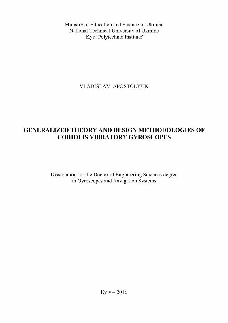
In order to improve efficiency of the CVG sensitive element design, the following
automated design software was developed, shown in Fig. 16.
Fig. 16. Main view of the MG CAD software
This software allows not only to design CVG sensitive element with tracking of its
measurement performances, and also to export the final design into mask files, supporting such formats as GDSII or CIF, that later can be used to fabricate the sensitive element using modern microelectronic technologies. Fabricated sensitive element is shown in Fig. 17, and general view of the CVG in a testing case is shown in Fig. 18.
Graphic plot in Fig. 29 shows results of the experimental testing of the designed and fabricated micromechanical CVG.

18
Fig. 17. Micromechanical CVG sensitive element
Fig. 18. Sensitive element assembled in a testing
case
Fig. 19. Dependence of the output voltage from the angular rate
As a result of the using grounded driving mode and lowered primary natural
frequency, good sensitivity was demonstrated even without vacuumization. Utilization of the developed technology of the automated sensitive element design for
micromechanical gyroscopes, complete development from the concept to the ready for fabrication mask files takes less than one day.
Thus, the following results were obtained in this chapter: expression for the forces acting on the sensitive element from the electrostatic comb drive, expressions for the natural frequency dependence from the driving voltages, optimal driving modes, expressions for scale factor and its linearity range, expressions for the primary natural frequency with acceptable non-linearity, expression for calculating of resolution and dynamic range, expressions for bias calculation and minimization, expressions for the amplitude and phase dynamic errors, methods of providing necessary bandwidth, and software for the efficient automated design of the micromechanical sensitive elements.

19
Chapter 6 deals with research and development of signals processing and errors
compensation methods and algorithms, aimed at improvement of the angular rate measurement performances.
Static optimal noise filters were synthesized in the dissertation, which can be applied to the demodulated CVG output as shown in Fig. 20.
W(s) G(s) 0
Fig. 20. Sensor noise filtering In case if sensor noise is a white noise, and angular rate is characterized with the
following power spectral density
22
22
)(sB
BsS
, (38)
where B is the cut-off frequency of the moveable object, producing angular rate, and is the angular rate standard deviation, then transfer function of the optimal sensor noise filter, synthesized using Wiener method, will be as follows:
].1
)12(
/[)](1[)(
2
2222
22
kB
kBkBs
sksBsG
(39)
If the sensor noise has a high-pass power spectral density, which is complementary to the band of the angular rate, then optimal filter transfer function will be
kBkBkss
ksBsG
)2(
)()(
2. (40)
Results of realistic numerical simulations of the white noise filter operation are shown in Fig. 21.
While sensor noises can be effectively filtered out using both static and dynamic optimal filtering, removing process noise, which is undistinguishable from the angular rate, is slightly more complicated task. The only way to separate the angular rate induced output from the process noise generated one, is to assume certain power spectral densities of these processes. Process noise , or disturbance, affects CVG in the same way as the external angular rate, as shown in Fig. 22.
For the angular rate having power spectral density (38), optimal process noise filter, derived using Wiener approach, will have the following transfer function:
)1(
)(1)(
2
2
Bsk
ksBsG . (41)

20
0 0.1 0.2 0.3 0.4 0.5 0.6 0.7 0.8-0.5
0
0.5
1
1.5
time, s
ang
ula
r ra
te,
rad/s
Fig. 21. Numerical simulation of the sensor noise filtering
(1 – input angular rate, 2 – noised output, 3 – filtered output)
W(s) G(s) 0
Fig. 22. CVG with added process noise, or disturbance In case of high-pass complementary disturbances, optimal static filter will have even
simpler transfer function
)(
)()(
sBk
ksBsG
. (42)
Results of the filter (41) realistic numerical simulations in case of white process noise and constant angular rate are shown in Fig. 23.
0 0.1 0.2 0.3 0.4 0.5 0.6 0.7 0.8
-0.1
-0.05
0
0.05
0.1
Time, s
Angu
lar
rate
, ra
d/s
Fig. 23. Process noise filtering results (1 – noised output, 2 – filtered output)
Geometrical imperfections in vibrating mechanical structures and/or sensing and
driving electrodes, as well as electrical connection between these electrodes could produce
1
2 3
1 2

21
non-zero output that is not related to the angular rate. Considering importance to have zero bias in CVGs for modern navigational applications, it is highly desired to be able to remove all non-gyroscopic components from the output signal.
In order to solve problem of undesired cross-couplings, decoupling system shown in Fig. 24 could be added to the primary and secondary outputs of the CVG sensitive element.
W1(s)
q1
W2(s) q2
C1(s)
C2(s)
x2
x1
G1(s)
G2(s)
y1
y2
H1(s)
H2(s)
Fig. 24. CVG sensitive element with decoupling structure
Low level transfer functions in modulated signals of the system in Fig. 24 are given
by the following expressions:
2
111
212
1)(
sssW ,
2
222
222
1)(
sssW ,
121211)()( csdgsC ,
212122)()( csdgsC .
(43)
Here 12
d and 21
d are the undesired cross-damping coefficients, 12
c and 21
c are the
undesired cross-stiffness coefficients. These undesired coefficients must be compensated, while the gyroscopic Coriolis term must be preserved. Derived in the dissertation decoupling transfer functions are as follows:
2
111
2
1212
12
)(
ss
sdcsG ,
2
222
2
2121
22
)(
ss
sdcsG ,
)2)(2(
)(1)(
2
222
22
111
2
21211
1ssss
sdcsgsH ,
.)2)(2(
)(1)(
2
222
22
111
2
12122
2
ssss
sdcsgsH
(44)
However, one could note that transfer functions (44) depend on the unknown angular rate, which requires few further steps to be undertaken in order to make this decoupling system feasible.
Considering the fact, that secondary oscillations are usually significantly lower then the externally driven primary oscillations, one could easily neglect the effect of the former
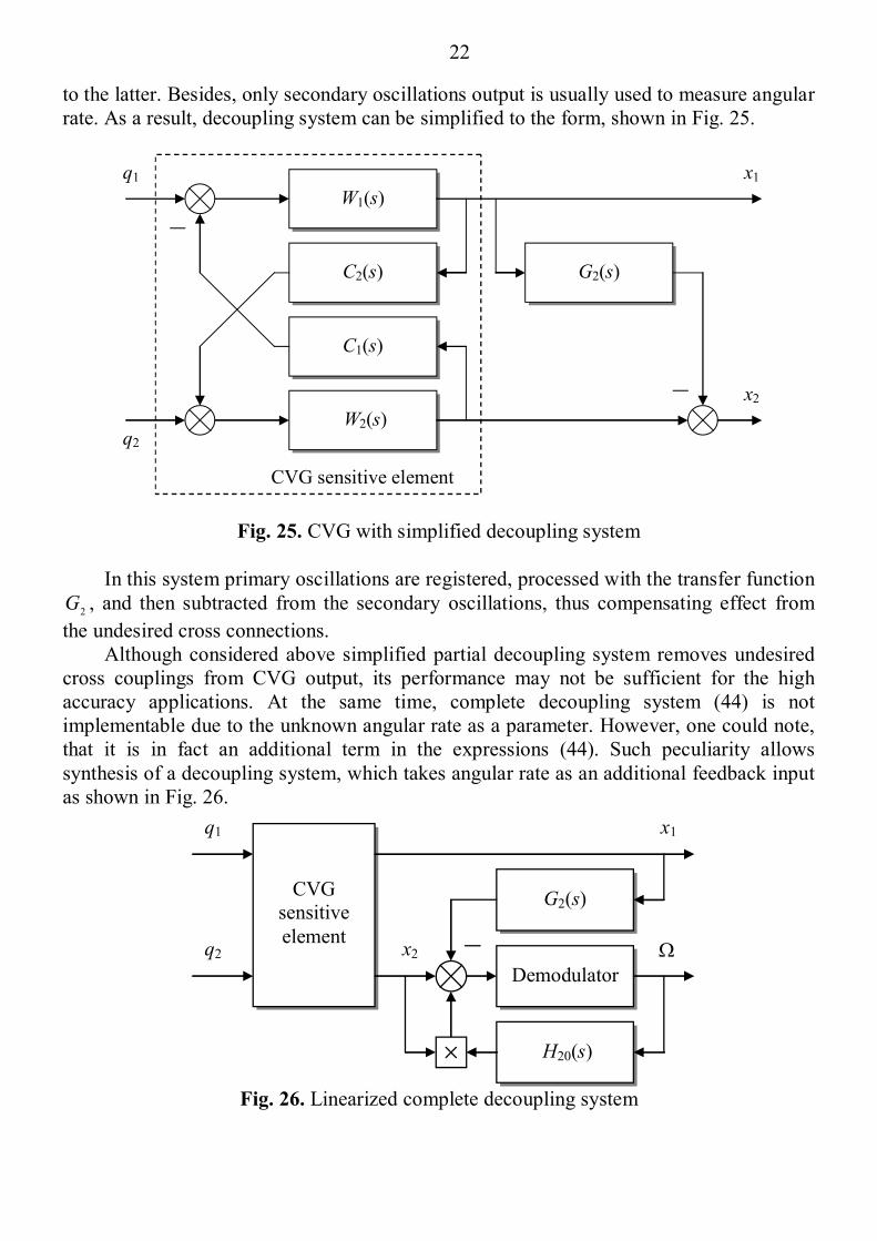
22
to the latter. Besides, only secondary oscillations output is usually used to measure angular rate. As a result, decoupling system can be simplified to the form, shown in Fig. 25.
W1(s)
q1
W2(s) q2
C1(s)
C2(s)
x1
G2(s)
x2
CVG sensitive element
Fig. 25. CVG with simplified decoupling system
In this system primary oscillations are registered, processed with the transfer function
2G , and then subtracted from the secondary oscillations, thus compensating effect from
the undesired cross connections. Although considered above simplified partial decoupling system removes undesired
cross couplings from CVG output, its performance may not be sufficient for the high accuracy applications. At the same time, complete decoupling system (44) is not implementable due to the unknown angular rate as a parameter. However, one could note, that it is in fact an additional term in the expressions (44). Such peculiarity allows synthesis of a decoupling system, which takes angular rate as an additional feedback input as shown in Fig. 26.
CVG sensitive element
q1
H20(s)
q2
x1
G2(s)
x2
Demodulator
Fig. 26. Linearized complete decoupling system
23
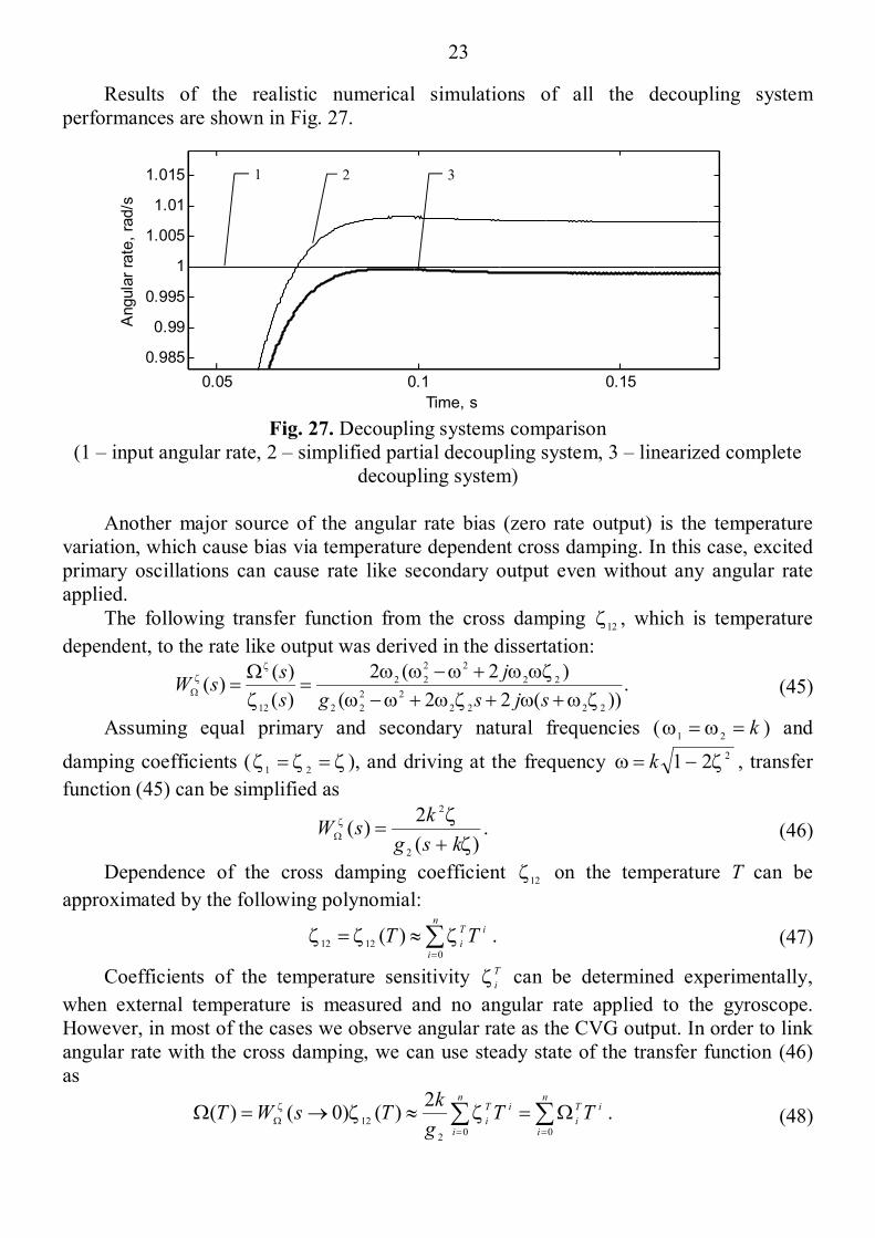
Results of the realistic numerical simulations of all the decoupling system performances are shown in Fig. 27.
0.05 0.1 0.15
0.985
0.99
0.995
1
1.005
1.01
1.015
Time, s
Angula
r ra
te,
rad/s
Fig. 27. Decoupling systems comparison
(1 – input angular rate, 2 – simplified partial decoupling system, 3 – linearized complete decoupling system)
Another major source of the angular rate bias (zero rate output) is the temperature
variation, which cause bias via temperature dependent cross damping. In this case, excited primary oscillations can cause rate like secondary output even without any angular rate applied.
The following transfer function from the cross damping 12
, which is temperature
dependent, to the rate like output was derived in the dissertation:
.))(22(
)2(2
)(
)()(
2222
22
22
22
22
22
12
sjsg
j
s
ssW (45)
Assuming equal primary and secondary natural frequencies ( k21
) and
damping coefficients ( 21
), and driving at the frequency 221 k , transfer
function (45) can be simplified as
)(
2)(
2
2
ksg
ksW . (46)
Dependence of the cross damping coefficient 12
on the temperature T can be
approximated by the following polynomial:
n
i
iT
i TT0
1212 )( . (47)
Coefficients of the temperature sensitivity T
i can be determined experimentally,
when external temperature is measured and no angular rate applied to the gyroscope. However, in most of the cases we observe angular rate as the CVG output. In order to link angular rate with the cross damping, we can use steady state of the transfer function (46) as
n
i
iT
i
n
i
iT
iTT
g
kTsWT
002
12
2)()0()( . (48)
1 2 3

24
In order to efficiently compensate transient processes in the CVG sensitive element dynamics that are caused by the temperature variations, we can apply developed earlier decoupling system (Fig. 25), where compensating transfer function is
2
222
2
112
22
2)(
ss
ssG . (49)
Here 12
is the temperature dependent cross damping coefficient defined earlier by
(47). Taking measurements from the temperature sensor we can combine its output with the measured primary oscillations in order to remove effect from the temperature variations at the low modulated level. Results of the realistic numerical simulations of such system operation are shown in Fig. 28.
0 0.1 0.2 0.3 0.4 0.5 0.6 0.7 0.8 0.9 1
-2
0
2
4
6
8
10
12
14x 10
-3
Time, s
Rate
, ra
d/s
Fig. 28. Temperature errors compensations system simulations
(1 – input angular rate, 2 – uncompensated output, 3 – compensated output) In case if temperature measurement are not available for the system, the following
static optimal filter of stochastic temperature influences was synthesized using Wiener approach in the dissertation:
)42(
)(2)(
2222
2
kBgsBkk
skBksG . (50)
It was assumed, that the angular rate has a low pass power spectral density with the cut-off frequency B, and temperature is a random walk stochastic process (integrated white noise).
Thus, the following results were obtained in this chapter: transfer functions of optimal static sensor and process noise filters, digital Kalman filter parameters to be used for sensor noise filtering, undesired cross-couplings compensation systems and its transfer functions, cross-sensitivity compensation systems for dynamically tuned gyroscopes, transfer function for the temperature error along with the temperature errors compensation systems and its transfer functions, and, finally, static optimal filter of stochastic temperature errors, when temperature reading are not available for the Coriolis vibratory gyroscope signal processing.
1 2
3

25
Chapter 7 deals with different aspects of closed loop control systems for Coriolis vibratory gyroscopes sensitive element.
In order to be able to efficiently perform recursive identification of the CVG sensitive element dynamics parameters, which are lately to be used in signal processing and control, different representations of CVG mathematical models in state space were studied in this chapter.
Obtained mathematical model in state space was then used to compare performances of different algorithms of recursive identification such as ARX, ARMAX, Box-Jenkins, within the proposed in the dissertation CVG identification framework, shown in Fig. 29.
CVG Filter *
v
Identification algorithm
θ
Fig. 29. CVG identification framework As a result of the conducted comparative analysis it was concluded that in case of
high measurement noises in the system ARMAX delivers best results, while in case of low level noises Box-Jenkins algorithm delivers best performance.
Necessity to measure angle of rotation instead of angular rate, or whole angle integrating gyroscope mode, led to specific sensitive elements designs, allowing it to operate as the classical Foucault pendulum. In the dissertation, for the first time another approach is developed, when any Coriolis vibratory gyroscope can be turned from the angular rate sensor into the integrating gyro by means of applying feedback control loop at the level of demodulated signals.
In term of demodulated signals CVG with the negative feedback control loop is shown in Fig. 30.
W (s)
G(s)
0
y
Fig. 30. CVG with the feedback control loop

26
Here is the measured angular rate, 0
is the unknown input angular rate, and
)(sW is the CVG transfer function, given by (16).
In order to implement integrating gyroscope mode, the following feedback control transfer function was synthesized in the dissertation:
)1()(
sk
sksG . (51)
It is important to remember that transfer function (51) was derived in terms of demodulated signals, and in order to be applied to the input of secondary oscillations as
2q
it must be modulated back with the primary oscillations according to the following expression:
)()()(122
txtygtq . (52)
Applying signal (52) to the sensitive element along its secondary motion leads to reduced actual secondary oscillations, while feedback signal y becomes new CVG output, implementing desired integrating mode. Numerical simulation of the CVG operation is shown in Fig. 31 and 32.
Кут
ова ш
вид
кіст
ь, р
ад
/с
Рис. 31. Integrated CVG signals: 1 – secondary output in integrating mode, 2 – noised
secondary output, 3 – input angular rate Obtained feedback controller (51) reduces secondary motion of the sensitive element,
and also reduces influence of the measurement noises on the integrated output. Since secondary oscillations amplitude in Coriolis vibratory gyroscopes is linearly
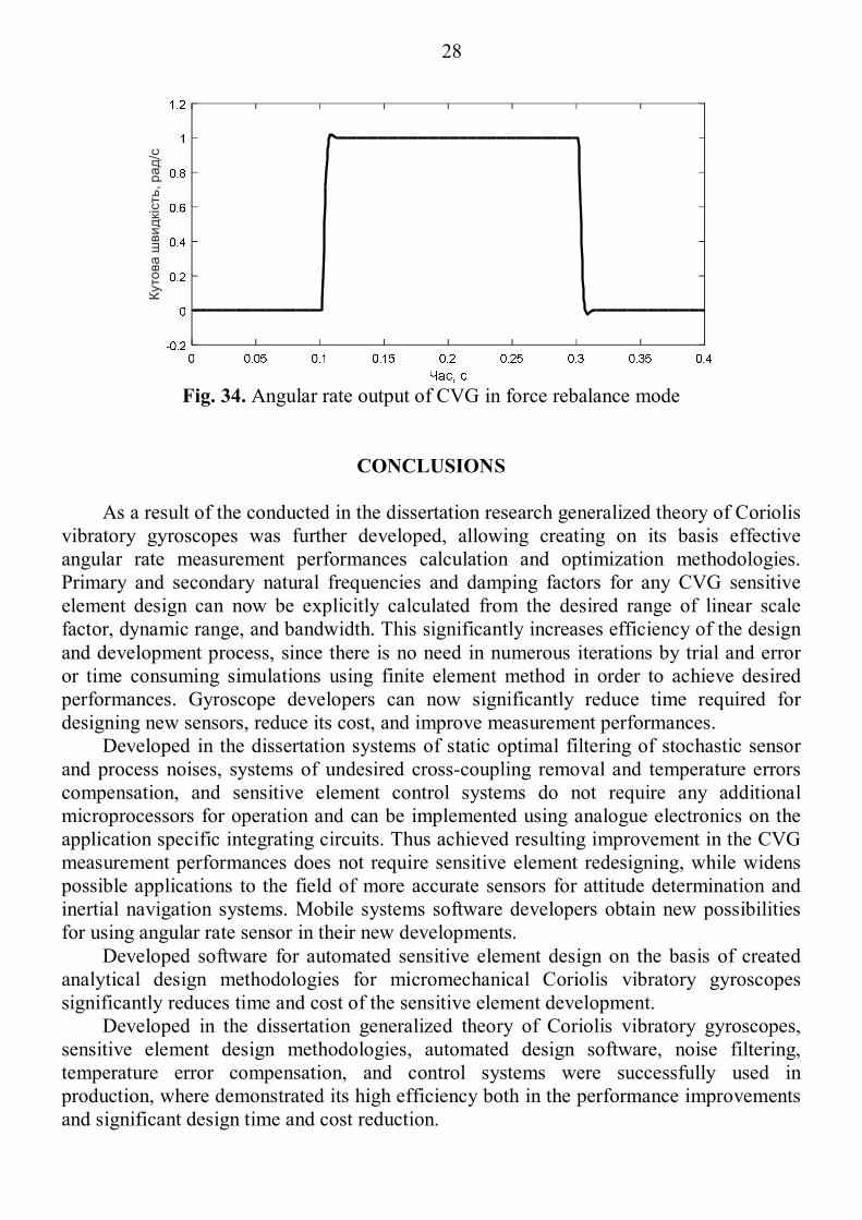
related to the angular rate, measurement range is naturally limited by the sensitive element design and its ability to deflect in its secondary motion. In order to improve the measurement performances both in terms of measurement range and bandwidth, force rebalance mode is implemented. In this mode secondary oscillations are suppressed, and suppressing signal is used as the angular rate measurement. The following feedback control transfer function for the system in Fig. 30 was derived in the dissertation, which implements force rebalance operation mode for CVGs:
ks
sk
Tks
sksG
1)( . (52)
1 2 3

27
0 0.05 0.1 0.15 0.2 0.25 0.3 0.35 0.4
-0.05
0
0.05
0.1
0.15
0.2
0.25
0.3
Time, s
Angle
, ra
d
Fig. 32. Integrating CVG feedback output
Here T/1 is the desired reaction frequency of the angular rate sensor based on
CVG. Resulting physical secondary motion of the sensitive element is shown in Fig. 33 and the angular rate measurements from the feedback loop are shown in Fig. 34.
Кут
ова
шви
дкі
сть
, р
ад
/с
Fig. 33. Compensated CVG: 1 – compensated secondary motion,
2 – input angular rate Analysis of the compensated CVG output in presence of high sensor noises
demonstrated that these noises are not reduced and intermediate noise filtering may be required.
Thus, the following results were obtained in this chapter of the dissertation: generalized mathematical model of CVG sensitive element in state space, sensitive element dynamics recursive identification frame, structure and transfer functions of CVG control systems, implementing whole angle integrating and force rebalance operation modes.
1 2
28
Кут
ова
шви
дкі
сть, р
ад
/с
Fig. 34. Angular rate output of CVG in force rebalance mode
CONCLUSIONS As a result of the conducted in the dissertation research generalized theory of Coriolis
vibratory gyroscopes was further developed, allowing creating on its basis effective angular rate measurement performances calculation and optimization methodologies. Primary and secondary natural frequencies and damping factors for any CVG sensitive element design can now be explicitly calculated from the desired range of linear scale factor, dynamic range, and bandwidth. This significantly increases efficiency of the design and development process, since there is no need in numerous iterations by trial and error or time consuming simulations using finite element method in order to achieve desired performances. Gyroscope developers can now significantly reduce time required for designing new sensors, reduce its cost, and improve measurement performances.
Developed in the dissertation systems of static optimal filtering of stochastic sensor and process noises, systems of undesired cross-coupling removal and temperature errors compensation, and sensitive element control systems do not require any additional microprocessors for operation and can be implemented using analogue electronics on the application specific integrating circuits. Thus achieved resulting improvement in the CVG measurement performances does not require sensitive element redesigning, while widens possible applications to the field of more accurate sensors for attitude determination and inertial navigation systems. Mobile systems software developers obtain new possibilities for using angular rate sensor in their new developments.
Developed software for automated sensitive element design on the basis of created analytical design methodologies for micromechanical Coriolis vibratory gyroscopes significantly reduces time and cost of the sensitive element development.
Developed in the dissertation generalized theory of Coriolis vibratory gyroscopes, sensitive element design methodologies, automated design software, noise filtering, temperature error compensation, and control systems were successfully used in production, where demonstrated its high efficiency both in the performance improvements and significant design time and cost reduction.

29
LIST OF PUBLICATIONS Books and Journal Papers 1. Apostolyuk V. Coriolis Vibratory Gyroscopes: Theory and Design / Vladislav
Apostolyuk. – Springer (USA) . – 2015. – 117 p. 2. Apostolyuk V. Efficient design of micromechanical gyroscopes / V. Apostolyuk,
V.J. Logeeswaran, F.E.H. Tay // Journal of Micromechanics and Microengineering. – 2002. –Vol. 12. – P. 948-954.
3. Apostolyuk V. Dynamics of Micromechanical Coriolis Vibratory Gyroscopes / V. Apostolyuk, F.E.H. Tay // Sensor Letters. – 2004. –Vol. 2. – No 3-4. – P. 252-259.
4. Apostolyuk V. Theory and Design of Micromechanical Vibratory Gyroscopes / V. Apostolyuk // MEMS/NEMS Handbook: collection of scientific papers. – Springer (USA) . – 2006. – Vol. 1. – Ch. 6. – P. 173-195.
5. Апостолюк В.О. Метод синтезу датчика кутової швидкості на динамічно настроюваному гіроскопі / О.В. Збруцький, В.О. Апостолюк, О.С. Апостолюк // Наукові вісті Національного технічного університету України “КПІ”. – 2000. – № 5. – С. 103-109.
6. Apostolyuk V. Dynamic Errors of Coriolis Vibratory Gyroscopes / V. Apostolyuk // Механіка гіроскопічних систем.– 2008.– №19.– С.230-239.
7. Apostolyuk V. Transient Process Analysis of Coriolis Vibratory Gyroscopes / V. Apostolyuk, A. Apostolyuk // Механіка гіроскопічних систем.– 2008.– №19.– С.230-239.
8. Apostolyuk V. Optimal Filtering of Stochastic Disturbances for Coriolis Vibratory Gyroscopes / V. Apostolyuk // Інформаційні системи, механіка та керування.– 2009. – №3. – С.20-30.
9. Apostolyuk V. Dynamics of Coriolis Vibratory Gyroscopes in Control Systems / V. Apostolyuk // Системи управління, навігації та зв’язку. – 2010. – №1(13). – С.62-66.
10. Apostolyuk V. Mathematical Model of Coriolis Vibratory Gyroscopes Motion Trajectory / V. Apostolyuk, I. Gorbunovich // Механіка гіроскопічних систем.– 2010.– №21.– С.5-12.
11. Apostolyuk V. Synthesis of Compensated Coriolis Vibratory Gyroscopes / V. Apostolyuk, Z. Didyk // Proceedings of NAU. – 2010. – №3. – С.55-60.
12. Apostolyuk V. Optimal Sensor Noise Filtering for Coriolis Vibratory Gyroscopes / V. Apostolyuk // Механіка гіроскопічних систем.– 2010.– №22.– С.5-12.
13. Апостолюк В.О. Вплив температури на динаміку коріолісового вібраційного гіроскопа / В.В. Возний, В.О. Апостолюк // Інформаційні системи, механіка та керування.– 2011. – №6. – С.48-56.
14. Apostolyuk V. Сross-coupling compensation for Coriolis vibratory gyroscopes / V. Apostolyuk // Механіка гіроскопічних систем.– 2011.– №23.– С.5-13.
15. Apostolyuk V. Excitation of Primary Oscillations in Micromechanical Vibratory Gyroscopes / V. Apostolyuk // Військово-технічний збірник.– 2011.– №2(5).– С.130-135.

30
16. Apostolyuk V. Demodulated Kalman Filtering for Coriolis Vibratory Gyroscopes / V. Apostolyuk // Інформаційні системи, механіка та керування.– 2011. – №7. – С.116-125.
17. Apostolyuk V. Temperature Errors Compensation in Coriolis Vibratory Gyroscopes / V. Apostolyuk, V. Chikovani // Механіка гіроскопічних систем.– 2012.– №25.– С. 22-29.
18. Apostolyuk V. Temperature Error Model in Coriolis Vibratory Gyroscopes / V. Apostolyuk, V. Chikovani // Electronics and Control Systems.– 2012. – №4 (34). – С. 155-158.
19. Apostolyuk V. Demodulated Dynamics and Optimal Noise Filtering for Coriolis Vibratory Gyroscopes / V. Apostolyuk // Військово-технічний збірник.– 2013.– №1(8).– С. 81-88.
20. Apostolyuk V. Dynamics of Trajectory Rotation in Coriolis Vibratory Gyroscopes / V. Apostolyuk // Механіка гіроскопічних систем.– 2013.– №26.– С. 15-21.
Conference Papers 21. Apostolyuk V. Analytical Design of Coriolis Vibratory Gyroscopes / V.
Apostolyuk, V.J. Logeeswaran, F.E.H. Tay // Symposium Gyro Technology: proceedings. – Stuttgart (Germany) . – 2002. – P. 2.1-2.15.
22. Apostolyuk V. Coriolis Vibratory Gyroscopes in Control Systems / V. Apostolyuk // Авіа-2009: ІХ міжнародна науково-техн. конф., 2009 р.: збірник доповідей. – К.: НАУ, 2009.– Ч. 2.– С. 9.1-9.4.
23. Apostolyuk V. Demodulated Dynamics and Optimal Filtering for Coriolis Vibratory Gyroscopes / V. Apostolyuk // 17-th St. Petersburg international conference on integrated navigation systems: proceedings. – St. Petersburg (Russia). – 2010. – P. 57-59.
24. Apostolyuk V. Compensation Algorithms for Coriolis Vibratory Gyroscopes / V. Apostolyuk, Z. Didyk // Methods and Systems of Navigation and Motion Control: 1-st international conference, 13-16 October 2010 р.: proceedings. – К.: НАУ, 2010.– С. 124-127.
25. Апостолюк В.О. Вплив температури на динаміку коріолісового вібраційного гіроскопа / В.В. Возний, В.О. Апостолюк // Гіротехнології, навігація керування рухом і конструювання авіаційно-космічної техніки: VІІІ міжнародна наук. техн. конф., 21-22 квітня 2011 р.: збірник доповідей. – К.: НТУУ «КПІ», 2011. – Ч. 1. – С. 48-51.
26. Apostolyuk V. Cross-coupling Compensation for Coriolis Vibratory Gyroscopes / V. Apostolyuk, I. Ivanenko // Авіа-2011: Х міжнародна науково-технічна конференція, 19-21 квітня 2011 р.: збірник доповідей. – К.: НАУ, 2011.– Том 3.– С. 9.35-9.38.
27. Apostolyuk V. Modelling Trajectory Rotation in Coriolis Vibratory Gyroscopes / V. Apostolyuk // Авіація в ХХІ сторіччі – Безпека в авіаційних та космічних технологіях: 5-й всесвітньій конгрес, 25-27 вересня 2012 р.: збірник доповідей. – К.: НАУ, 2012.– Ч. 2.– С. 33.1-33.8.
28. Apostolyuk V. Modelling Temperature Errors in Coriolis Vibratory Gyroscopes / V. Apostolyuk, V. Chikovani // Methods and Systems of Navigation and Motion Control:

31
2-nd international conference, 9-12 October 2012: proceedings. – К.: IEEE, 2012.– С. 116-118.
29. Apostolyuk V. Application of Recursive Identification to Coriolis Vibratory Gyroscopes / V. Apostolyuk, O. Apostolyuk // Гіротехнології, навігація, керування рухом і конструювання авіаційно-космічної техніки: ІХ Міжнародна науково-технічна конференція, 17-18 квітня 2013 р.: збірник доповідей. – К.: НТУУ "КПІ", 2013. – С. 147-151.
30. Apostolyuk V. Whole Angle Force Rebalance Control for Coriolis Vibratory Gyroscopes / V. Apostolyuk // Methods and Systems of Navigation and Motion Control: 3-rd international conference, 14-17 October 2014: proceedings. – К.: IEEE, 2014.– С. 69-61.
ABSTRACT
Apostolyuk V. O. Generalized theory and design methodologies of Coriolis
vibratory gyroscopes. – Manuscript. Dissertation for the Doctor of Engineering Sciences degree in specialty 05.11.03 –
Gyroscopes and Navigation Systems. – National Technical University of Ukraine “Kyiv Polytechnic Institute”, Kyiv, 2016.
Coriolis vibratory gyroscopes theory was generalized and further developed in this dissertation along with the sensitive element design methodologies. Motion equations for sensitive elements with linear, rotational, and wave both primary and secondary motions were derived and then generalized to the single system of two differential equations. This system was utilized to analyze sensitive element motions on a rotating basis in terms of amplitudes and phases of primary and secondary motions. Analysis of the sensitive element oscillations stability resulted in expressions for primary and secondary motion eigen frequencies as a functions of the sensitive element parameters and angular rate.
Expressions for calculating scale factor, dynamic range, bias, and bandwidth using design parameters of sensitive element were derived. Angular rate measurement errors caused by scale factor non-linearity, vibrations, measurement and elastic axes misalignment, and angular rate variations were analysed and corresponding techniques for errors reduction and elimination were suggested. Analytical design methodologies, when such sensitive elements parameters as primary and secondary natural frequencies and relative damping factors are calculated directly from the desired main performances, were developed in this dissertation. As a result, high measurement performances of the designed and fabricated sensitive element were achieved and experimentally demonstrated.
Mathematical model of an electrostatic comb-drive, which is used to drive the sensitive element into primary oscillations, incorporating effects from non-linear capacity was developed. Driving efficiency analysis resulted in obtaining conditions for the most efficient excitation modes, one of which implements driving with doubled to driving signal frequency. As a result, efficient frequency separation of noise sources and sensing signals has been achieved. Natural frequency shift from capacity non-linearity was demonstrated both theoretically and experimentally. Comb drive design recommendations that improve its efficiency and implement harmonic excitations were suggested.
32
Micromachined sensitive element automated design software, which implements these design methodologies, was also developed. It effectively eliminates necessity for iterative design process and significantly reduces sensitive element design time. Complete mathematical model of the sensitive element motion was also used to develop systems of realistic simulation of gyroscope operation using Simulink/Matlab.
Mathematical model of Coriolis vibratory gyroscopes sensitive element is terms of demodulated signals was developed in the dissertation as well. This mathematical model was used to derive transfer functions of a dynamic system where angular rate is the input rather than system parameter as in the conventional models. Amplitude and phase responses of Coriolis vibratory gyroscopes from the angular rate frequency where used to both analyze amplitude and phase dynamic error and to develop methods of bandwidth and unit step transient process optimisation.
The derived set of the system transfer functions includes exact complex transfer function, slowly varying angular rate complex transfer function, split real and imaginary transfer functions, and the real valued simplified approximate transfer functions that connect input angular rate to the secondary amplitude and measured output angular rate. Performances of the latter transfer functions were studied and the acceptably good approximation of the sensitive elements within wide range of design parameters was demonstrated.
Coriolis vibratory gyroscope system transfer function was used to synthesise static optimal filters for stochastic process and sensor noises based on the Wiener method. Optimal filters were developed for the white and high-pass stochastic noises and disturbances. Angular rate was described by low-pass power spectral density. Excellent performances of the designed filters were demonstrated using realistic numerical simulations. Obtained filters are static and represented by relatively simple transfer functions. They can be implemented using analogue electronics within application specific integrated circuits.
Sensitive element motion trajectory analysis resulted in simple and accurate expressions for the trajectory parameters, enabling alternative approaches to the angular rate measurements. System transfer function was used to obtain simple transfer function from the angular rate to the angle of the sensitive element motion trajectory rotation.
Apart from signal processing algorithms research and development in demodulated signals, low level performance improving systems in modulated signals were developed as well. Suggested in the dissertation decoupling system is capable of highly efficient removal of undesired cross-couplings between primary and secondary oscillations. Simple system of partial decoupling is developed along with the non-linear and highly efficient complete decoupling system. This approach to decoupling was also used to design low-level system of cross-sensitivity removal and successfully applied to dynamically tuned gyroscopes. At the same time, the former decoupling systems were used to design temperature errors compensation systems in case when temperature readings are available in the system.
Finally, system transfer functions for Coriolis vibratory gyroscopes were used to research and develop sensitive element control systems in demodulated signals. Simple and robust control system along with its transfer functions was designed to implement angular rate integrating operation mode. Highly efficient rotation angle measurement in
33
presence of high noises was demonstrated using realistic numerical simulations. Force rebalance operation mode was implemented by another developed control system and its transfer functions. The latter system demonstrated improved performances of the angular rate measurements in terms of reaction time and measurement range.
Keywords: Coriolis vibratory gyroscope, dynamics, sensitive element, design methodologies, measurement error, signal processing, control