Embed Size (px)
Citation preview

gen4-uLCD-XXDT/DCT-CLB - GETTING STARTED MANUAL | 1

gen4-uLCD-XXDT/DCT-CLB - GETTING STARTED MANUAL | 2
CONTENTS
03 Introduction
System Requirements
• Hardware Requirements • Software Requirements
06 Connecting the Display Module to the PC
• Connection Options Using the 4D Programming Cable Using the uSB-PA5-II Using the 4D-UPA
• Let WS4 Identify the Display Module
09 Getting Started with a Simple Project
15 Workshop4 Pro
16 Application Notes
17 Reference Documents
20 Glossary
• Hardware • Software
WHAT’S IN THE BOX
gen4-Interface Board gen4-uLCD-XXDT/ DCT-CLB
30-way Flat Flex Cable (FFC)
Supporting documents, datasheet, CAD step models and application notes are available on the 4D Systems website.

gen4-uLCD-XXDT/DCT-CLB - GETTING STARTED MANUAL | 3
INTRODUCTION This Getting Started Manual is an introduction to the gen4-uLCD-XXDT /DCT-CLB and the WorkShop4 software IDE associated with it. This manual should be treated only as a useful starting point and not as a comprehensive reference document. Refer to Application Notes for a list of all the detailed reference documents.
In this Getting Started Manual we will briefly focus on the following topics: • Hardware and Software Requirements • Connecting the Display Module to your PC • Getting Started with Simple Projects • Projects using gen4-uLCD-XXDT/DCT-CLB • Application Notes • Reference Documents
The gen4-uLCD-XXDT/DCT-CLB is part of the gen4 series of display modules designed and manufactured by 4D Systems. Depending on your purchase, the modules feature either a 2.4”, 2.8", 3.2", 3.5", 4.3”, 5.0” or 7.0" colour TFT LCD display, with resistive or capacitive touch. It is powered by the feature-rich 4D Systems Diablo16 graphics processor, which offers an array of functionality and options for the designer/integrator/user Intelligent display modules are embedded solutions used in various applications in manufacturing automotive, medical, home automation, consumer electronics, and other various industries. In fact, there are very few embedded designs on the market today that do not have a display. Even many consumer white goods and kitchen appliances incorporate some form of display. Buttons, rotary selectors, switches and other input devices are being replaced by more colourful and easier-to-use touch screen displays in industrial machines, thermostats, drink dispensers, 3D printers, commercial applications - virtually any electronic application. For designers/users to be able to create and design a user interface for their applications that will run on 4D intelligent display modules, 4D Systems provides a free and user-friendly software IDE (Integrated Development Environment) called “Workshop4” or “WS4”. This software IDE is discussed in more detail in the section “System Requirements”.

gen4-uLCD-XXDT/DCT-CLB - GETTING STARTED MANUAL | 4
SYSTEM REQUIREMENTS The following subsections discuss the hardware and software requirements for this manual.
1 Hardware
1.1 Intelligent Display Module and Accessories
The gen4-uLCD-XXDT/DCT-CLB intelligent display module and its accessories (interface board and flat flex cable) should be included in the box delivered to you after your purchase from our website or through one of our distributors. Please refer to the section “What’s in the Box” for images of the display module and its accessories.
1.2 Programming Module
The programming module is a separate device required to connect the display module to a Windows PC. 4D Systems offers the following programming modules:
• 4D Programming Cable • uUSB-PA5-II Programming Adaptor • 4D-UPA
To use any of the programming modules, the corresponding driver must first be installed in the PC. You may refer to the product page of the given module for more information and detailed instruction.
Note: These devices are available separately from 4D Systems. Please refer to the product pages for more information.
1.3 microSD Card
Workshop4 has built-in widgets that can be used to design your display UI. In order to use these widgets, they should be saved first into the microSD Card along with the other graphic files during the compilation step.
Note: microSD Card is optional and is only needed with projects that are utilizing graphical files. Please note as well that not all cards on the market are SPI compatible, and therefore not all cards can be used in 4D Systems products. Buy with confidence, choose the cards recommended by 4D Systems.

gen4-uLCD-XXDT/DCT-CLB - GETTING STARTED MANUAL | 5
1.4 Windows PC
Workshop4 only runs on Windows operating system. It is recommended to be used on Windows 7 up to Windows 10 but should still work with Windows XP. Some older OS's such as ME and Vista has not been tested for quite some time, however, the software should still work. If you want to run the Workshop4 on other operating systems like Mac or Linux, it is recommended to set up a virtual machine (VM) on your PC.
2 Software
2.1 Workshop4 IDE
Workshop4 is a comprehensive software IDE for Microsoft Windows that provides an integrated software development platform for all of the 4D family of processors and modules. The IDE combines the Editor, Compiler, Linker and Downloader to develop complete 4DGL application code. All user application code is developed within the Workshop4 IDE.
Workshop4 includes four development environments, for the user to choose based on application requirements or even user skill level- Designer, ViSi–Genie, ViSi and Serial.
Workshop4 Environments
Designer
This environment enables the user to write 4DGL code in its natural form to program the display module. ViSi – Genie
An advanced environment that doesn't require any 4DGL coding at all, it is all done automatically for you. Simply lay the display out with the objects you want (similar to ViSi), set the events to drive them and the code is written for you automatically. ViSi-Genie provides the latest rapid development experience from 4D Systems. ViSi
A visual programming experience that enables drag-and-drop type placement of objects to assist with 4DGL code generation and allows the user to visualize how the display will look while being developed. Serial
This environment is also provided to transform the display module into a slave serial display module, allowing the user to control the display from any host microcontroller or device with a serial port.
gen4-uLCD-XXDT/DCT-CLB - GETTING STARTED MANUAL | 6
Install Workshop4
Download links for the WS4 installer and installation guide can be found on the Workshop4 product page.
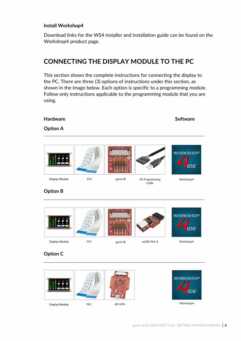
CONNECTING THE DISPLAY MODULE TO THE PC This section shows the complete instructions for connecting the display to the PC. There are three (3) options of instructions under this section, as shown in the image below. Each option is specific to a programming module. Follow only instructions applicable to the programming module that you are using.
Hardware Software
Option A
Option B
Option C
Display Module
FFC
Workshop4 gen4-IB
4D Programming Cable
Display Module
Display Module
FFC
FFC
gen4-IB
4D-UPA
uUSB-PA5-II
Workshop4
Workshop4
gen4-uLCD-XXDT/DCT-CLB - GETTING STARTED MANUAL | 7
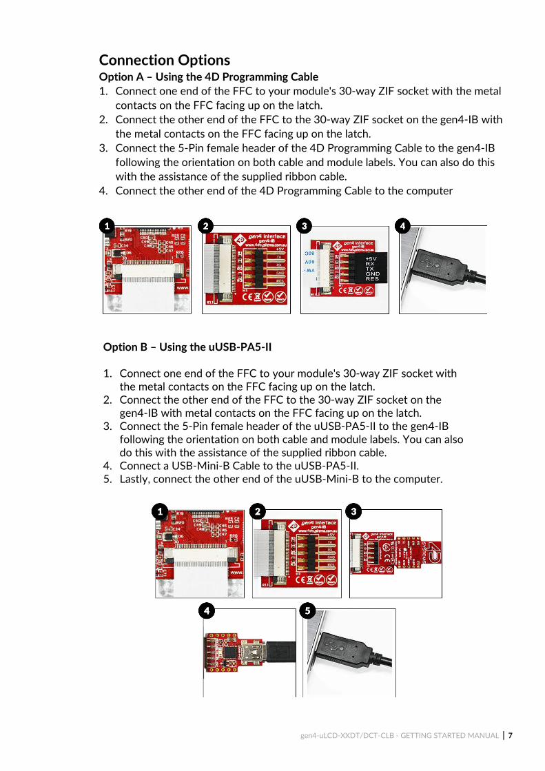
Connection Options Option A – Using the 4D Programming Cable 1. Connect one end of the FFC to your module's 30-way ZIF socket with the metal
contacts on the FFC facing up on the latch. 2. Connect the other end of the FFC to the 30-way ZIF socket on the gen4-IB with
the metal contacts on the FFC facing up on the latch. 3. Connect the 5-Pin female header of the 4D Programming Cable to the gen4-IB
following the orientation on both cable and module labels. You can also do this with the assistance of the supplied ribbon cable.
4. Connect the other end of the 4D Programming Cable to the computer
Option B – Using the uUSB-PA5-II
1. Connect one end of the FFC to your module's 30-way ZIF socket with the metal contacts on the FFC facing up on the latch.
2. Connect the other end of the FFC to the 30-way ZIF socket on the gen4-IB with metal contacts on the FFC facing up on the latch.
3. Connect the 5-Pin female header of the uUSB-PA5-II to the gen4-IB following the orientation on both cable and module labels. You can also do this with the assistance of the supplied ribbon cable.
4. Connect a USB-Mini-B Cable to the uUSB-PA5-II. 5. Lastly, connect the other end of the uUSB-Mini-B to the computer.

gen4-uLCD-XXDT/DCT-CLB - GETTING STARTED MANUAL | 8
Option C – Using the 4D-UPA
1. Connect one end of the FFC to your module’s 30 way ZIF socket with
the metal contacts on the FFC facing up on the latch. 2. Connect the other end of the FFC to the 30-way ZIF socket on the 4D-
UPA with the metal contacts on the FFC facing up on the latch. 3. Connect the USB-Micro-B Cable to the 4D-UPA. 4. Lastly, connect the other end of the USB-Micro-B Cable to the
computer.
Let WS4 Identify the Display Module
After following the appropriate set of instructions in the previous section, you now need to configure and setup Workshop4 to make sure that it identifies and connects to the correct display module.
1. Open Workshop4 IDE and create a new project. 2. Select the display module you’re using from the list. 3. Select your desired orientation for your project. 4. Click next. 5. Choose a WS4 Programming Environment. Only the compatible
programming environment for the display module will be enabled.

gen4-uLCD-XXDT/DCT-CLB - GETTING STARTED MANUAL | 9
6. Click on the COMMS tab, select the COM port the display module is connected to from the dropdown list.
7. Click on the RED Dot to start scanning for the display module. A YELLOW dot will show while scanning. Make sure that your module is connected properly.
8. Lastly, a successful detection will give you a BLUE Dot with the name of the display module shown alongside it.
9. Click on the Home tab to start creating your project.

gen4-uLCD-XXDT/DCT-CLB - GETTING STARTED MANUAL | 10
GETTING STARTED WITH A SIMPLE PROJECT
After successfully connecting the display module to the PC using your programming module, you can now start creating a basic application. This section shows how to design a simple user interface using the ViSi-Genie environment and utilizing the slider and gauge widgets. The resulting project consists of a slider (an input widget) controlling a gauge (an output widget). The widgets can also be configured to send event messages to an external host device through the serial port.
Create a New Visi-Genie Project You can create a Visi-Genie project by opening Workshop and by choosing the display type and the environment that you want to work with. This project will be using the Visi-Genie environment. 1. Open Workshop4 by double-clicking the icon. 2. Create New Project with the New Tab. 3. Choose your display type. 4. Click Next. 5. Choose Visi-Genie Environment.

gen4-uLCD-XXDT/DCT-CLB - GETTING STARTED MANUAL | 11
Add a Slider Widget To add a slider widget, simply click on the Home tab and choose the Inputs Widgets. From the list, you may choose the type of widget that you want to use. In this case, the slider widget is selected.
Simply drag-and-drop the widget towards the What-You-See-Is-What-You-Get (WYSIWYG) section.
Add a Gauge Widget To add a gauge widget, go to the Gauges section and choose the gauge type that you want to use. In this case the Coolgauge widget is selected.
Drag and drop it towards the WYSIWYG section to proceed.

gen4-uLCD-XXDT/DCT-CLB - GETTING STARTED MANUAL | 12
Link the Widget Input widgets can be configured to control an output widget. To do this, just click on the input (in this example, the slider widget) and go to its Object Inspector Section and click the Events Tab. There are two events available under the events tab of an input widget - OnChanged and OnChanging. These events are triggered by touch actions performed on the input widget. The OnChanged event is triggered every time an input widget is released. On the other hand, the OnChanging event is continuously triggered while an input widget is being touched. In this example, the OnChanging event is used. Set the event handler by clicking on the ellipsis symbol for the OnChanging event handler.
The on-event selection window appears. Select coolgauge0Set, then click OK.
Configure the Input Widget to Send Messages to a Host An external host, connected to the display module through the serial port, can be made aware of the status of a widget. This can be achieved by configuring the widget to send event messages to the serial port. To do this, set the OnChanged event handler of the slider widget to Report Message.

gen4-uLCD-XXDT/DCT-CLB - GETTING STARTED MANUAL | 13
Build and Compile the Project To Build/Upload the project, click the (Build) Copy/Load icon.
Copy the Required Files to the microSD Card Graphics data for the widgets will actually be stored to a microSD card, which will be accessed by the graphics processor of the display module during runtime. The graphics processor will then render the widgets on the display.
At this point, WS4 generates the required graphics files and will prompt you for the drive to which the microSD card is mounted. Make sure that the microSD card is properly mounted to the PC, then select the correct drive in the Copy Confirmation window, as shown in the image below.
Click OK after the files are transferred to the microSD card. Unmount the microSD Card from the PC and insert it to the display module's microSD Card slot.
gen4-uLCD-XXDT/DCT-CLB - GETTING STARTED MANUAL | 14
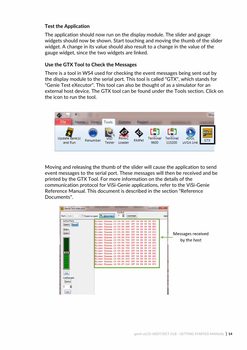
Test the Application The application should now run on the display module. The slider and gauge widgets should now be shown. Start touching and moving the thumb of the slider widget. A change in its value should also result to a change in the value of the gauge widget, since the two widgets are linked. Use the GTX Tool to Check the Messages There is a tool in WS4 used for checking the event messages being sent out by the display module to the serial port. This tool is called "GTX", which stands for "Genie Test eXecutor". This tool can also be thought of as a simulator for an external host device. The GTX tool can be found under the Tools section. Click on the icon to run the tool.
Moving and releasing the thumb of the slider will cause the application to send event messages to the serial port. These messages will then be received and be printed by the GTX Tool. For more information on the details of the communication protocol for ViSi-Genie applications, refer to the ViSi-Genie Reference Manual. This document is described in the section "Reference Documents".

gen4-uLCD-XXDT/DCT-CLB - GETTING STARTED MANUAL | 15
2.2 Workshop4 Pro Standard Workshop4 has its capabilities to make a UI design, but a richer and more interactive design can be achieved with Worskhop4 Pro. The Workshop4 PRO License unlocks Genie Magic for the ViSi-Genie environment, along with the Smart Widget Editor for both ViSi and ViSi-Genie Environment. New features and additions continue to be developed, and updates are made available for free once the license has been purchased.
Genie Magic
Genie Magic is an upgraded version of the standard ViSi-Genie environment. With this advanced environment, the user can overcome the limitation of the standard ViSi-Genie environment which is its strictly drag-and-drop and event-adding type of programming; while the code can be added using another microcontroller (i.e. Arduino) interfaced to a 4D Systems display. Genie Magic brings the ability to add standard 4DGL code to various points within the ViSi-Genie environment. This enables you to have all the advantages of ViSi-Genie but with the new ability to add extra 4DGL where you want it.
The Magic tab automatically appears once the Workshop4 Pro License has been purchased.
Smart Widgets Editor
Smart Widget Editor brings a comprehensive tool which allows you to create and animate Gauges, Sliders, Knobs and more, using the tools provided. This allows you to easily add custom graphics and build customised widgets, exactly as you want them.
Smart Widgets are custom widgets designed using the Smart Widgets Editor and Workshop4 Pro comes with 30+ different examples of smart widgets.
Note: Workshop4 PRO is an OPTIONAL upgrade to unlock advanced features. Workshop4 is still FREE to download and use, however, the PRO features requires a paid license to unlock the additional features. To know more about Workshop4 Pro and on how to purchase the license, you may go to Workshop4 PRO product page.

gen4-uLCD-XXDT/DCT-CLB - GETTING STARTED MANUAL | 16
APPLICATION NOTES
App Note Title Description Supported Environment
4D-AN-00117 Designer Getting Started - First Project
This application note shows how to create a new project using the Designer Environment. It also introduces the basics of 4DGL (4D Graphics Language).
Designer
4D-AN-00119 ViSi Getting Started - First Project for Picaso and Diablo16
This application note shows how to create a new project using the ViSi Environment. It also introduces the basics of 4DGL (4D Graphics Language and the basic use of the WYSIWYG (What-You-See-Is-What-You-Get) screen.
ViSi
4D-AN-00001 ViSi-Genie Getting Started - First Project for Picaso Display Modules
The simple project developed in this application note demonstrates basic touch functionality and object interaction using the ViSi-Genie Environment. The project illustrates how input objects are configured to send messages to an external host controller and how these messages are interpreted.
ViSi-Genie
4D-AN-00090 Serial Picaso Getting Started - The SPE Application
This application note shows how to configure a 4D display to act as a serial slave and how to use the Serial Commander (one of the several tools available in Workshop) to send commands to the display. This knowledge will then allow the user to properly program any external host controller for the display module.
Serial

gen4-uLCD-XXDT/DCT-CLB - GETTING STARTED MANUAL | 17
REFERENCE DOCUMENTS ViSi-Genie is the environment recommended for beginners. This environment doesn't necessarily involve coding, which makes it the most user-friendly platform among the four environments. However, ViSi-Genie has its limitations. For users wanting more control and flexibility during application design and development, the Designer, ViSi, or Serial environment is recommended. ViSi and Designer allow users to write the code for their applications. The programming language used with 4D Systems graphics processors is called "4DGL". The Serial environment, on the other hand, transforms the display module into a slave serial device, allowing the user to control the display using any external host with a serial port. Essential reference documents that can be utilized for further study of the different environments are listed below. ViSi-Genie Reference Manual
ViSi-Genie does all the background coding, no 4DGL to learn, it does it all for you. This document covers the ViSi-Genie functions available for the PICASO and the DIABLO16 Processors and the communications protocol used known as the Genie Standard Protocol.
4DGL Programmer Reference Manual
4DGL is a graphics oriented language allowing rapid application development. An extensive library of graphics, text and file system functions and the ease of use of a language that combines the best elements and syntax structure of languages such as C, Basic, Pascal, etc. This document covers the language style, the syntax and flow control.
Internal Functions Manual
4DGL has a number of internal functions that can be used for easier programming. This document covers the internal (chip-resident) functions available for the Diablo16 Processor.
Diablo16 Processor Serial Reference Manual This document describes the Serial Environment, discusses how to configure a display module as a slave serial device, and describes all the commands available for controlling the display module with an external host.
gen4-uLCD-XXDT/DCT-CLB - GETTING STARTED MANUAL | 18
gen4-uLCD-24DT Datasheet
This document contains detailed information about the gen4-uLCD-24DT integrated display modules.
gen4-uLCD-28DT Datasheet
This document contains detailed information about the gen4-uLCD-28DT integrated display modules.
gen4-uLCD-32DT/DCT-CLB Datasheet
This document contains detailed information about the gen4-uLCD-32DT/DT-CLB integrated display modules.
gen4-uLCD-35DT/DCT-CLB Datasheet This document contains detailed information about the gen4-uLCD-35DT/DT-CLB integrated display modules.
gen4-uLCD-43DT/DCT-CLB Datasheet
This document contains detailed information about the gen4-uLCD-43DT/DT-CLB integrated display modules.
gen4-uLCD-50DT/DCT-CLB Datasheet
This document contains detailed information about the gen4-uLCD-50DT/DT-CLB integrated display modules.
gen4-uLCD-70DT/DCT-CLB Datasheet
This document contains detailed information about the gen4-uLCD-70DT/DT-CLB integrated display modules.
Workshop4 IDE User guide
This document provides an introduction to Workshop4, 4D Systems’ integrated development environment.
Note: For more information about Workshop4 in general, please refer to the Workshop4 IDE User Guide, available from the 4D Systems website.

gen4-uLCD-XXDT/DCT-CLB - GETTING STARTED MANUAL | 19
NOTES

gen4-uLCD-XXDT/DCT-CLB - GETTING STARTED MANUAL | 20
GLOSSARY
Hardware
1. 4D Programming Cable – is a USB to Serial-TTL UART converter cable. The cable provides a fast and simple way to connect all of the 4D devices that require TTL level serial interface to USB.
2. 4D-UPA – a universal programmer designed to work with multiple 4D Systems display modules.
3. Embedded System – is a programmed controlling and operating system with a dedicated function within a larger mechanical or electrical system, often with real-time computing constraints. It is embedded as part of a complete device often including hardware and mechanical parts.
4. Female Header – is a connector attached to a wire, cable, or piece of hardware, having one or more recessed holes with electrical terminals inside.
5. Micro USB cable – a type of cable used to connect the display to a computer.
6. microSD Card – a type of removable flash memory card used for storing information.
7. Processor – is a small chip that resides the 4D Systems displays. Its basic job is to receive input and provide the appropriate output.
8. Programming Adaptor – used for programming 4D Systems display modules, interfacing to a breadboard for prototyping, interfacing to Arduino and Raspberry Pi interfaces.
9. Resistive Touch Panel – is a touch-sensitive computer display composed of two flexible sheets coated with a resistive material and separated by an air gap or microdots.
10. uUSB-PA5-II – a USB to Serial-TTL UART bridge converter designed to work with 4D Systems display modules. It provides the user with multi baud rate serial data up to 3M baud rate.

gen4-uLCD-XXDT/DCT-CLB - GETTING STARTED MANUAL | 21
Software 1. Comm Port – a serial communication used to connect devices such as your
display.
2. Driver Device – is a particular form of software application that is designed to enable interaction with hardware devices. Without the required device driver, the corresponding hardware device fails to work.
3. Firmware – a specific class of computer software that provides the low-level control for the device's specific hardware.
4. GTX Tool – Genie Test Executor debugger. A tool used to check the data sent and received by the display.
5. GUI – It is a form of user interface that allows users to interact with electronic devices through graphical icons and visual indicators such as secondary notation, instead of text-based user interfaces, typed command labels or text navigation.
6. Image Files – are graphics files generated upon program compilation that should be saved into the microSD Card.
7. Object Inspector – a section in Workshop4 where the user can change the properties of a certain widget. This is where the widgets customization and Events configuration happen.
8. PmmC - The PmmC contains the low level micro-code information (analogy of that of a soft silicon) which define the characteristics and functionality of the PICASO processor. The chip-resident 4DGL functions are part of the PmmC configuration file and future proofing and enhancements are available via PmmC updates. The PmmC file is programmed into the module via the COM port.
9. Widget – graphical objects in Workshop4.
10. WYSIWYG – What-You-See-Is-What-You-Get. The Graphics Editor Section in Workshop4 where the user can drag and drop widgets.
Visit our website at: www.4dsystems.com.au
Technical Support: www.4dsystems.com.au/support
Sales Support: [email protected]
Copyright © 4D Systems, 2019, All Rights Reserved


![Design Considerations for Next Generation Wireless Power ......[Montanaro, JSSC ‘96] CLB CLB CLB CLB 65% 21% 9% 5% Interconnect Clock I/O CLB “Software” Energy Dissipation is](https://img.pdfslide.us/doc/110x75/6075f305565b1e4d845c5e4e/design-considerations-for-next-generation-wireless-power-montanaro-jssc.jpg)
![L16: Power Dissipation in Digital Systemsweb.mit.edu/6.111/www/s2006/LECTURES/l16.pdf · [Montanaro, JSSC ‘96] [A. Sinha, DAC] 65% 21% 9% 5% Interconnect Clock I/O CLB CLB CLB CLB](https://img.pdfslide.us/doc/110x75/6075f07be9a488213651b8cd/l16-power-dissipation-in-digital-montanaro-jssc-a96-a-sinha-dac-65-21.jpg)