Embed Size (px)
Citation preview
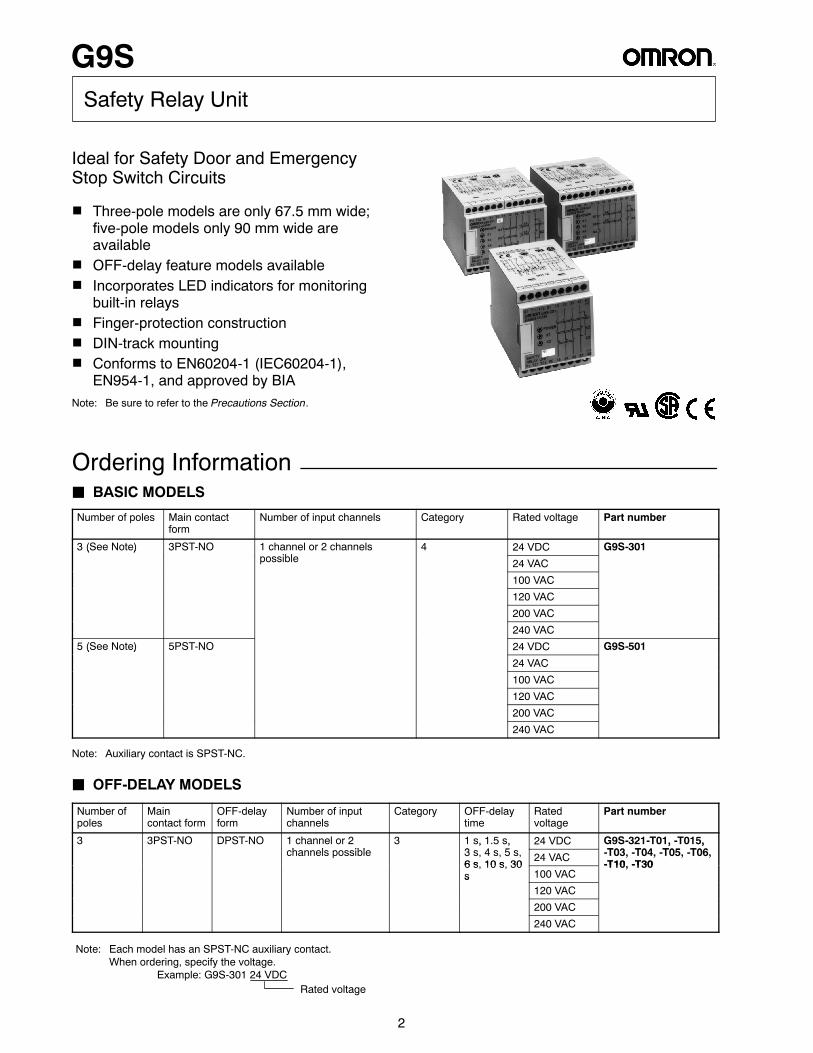
G9S
2
Safety Relay Unit
Ideal for Safety Door and EmergencyStop Switch Circuits
H Three-pole models are only 67.5 mm wide;five-pole models only 90 mm wide areavailable
H OFF-delay feature models availableH Incorporates LED indicators for monitoring
built-in relaysH Finger-protection constructionH DIN-track mountingH Conforms to EN60204-1 (IEC60204-1),
EN954-1, and approved by BIANote: Be sure to refer to the Precautions Section.
Ordering InformationJ BASIC MODELS
Number of poles Main contactform
Number of input channels Category Rated voltage Part number
3 (See Note) 3PST-NO 1 channel or 2 channelsibl
4 24 VDC G9S-301( )possible 24 VAC
100 VAC
120 VAC
200 VAC
240 VAC
5 (See Note) 5PST-NO 24 VDC G9S-501( )
24 VAC
100 VAC
120 VAC
200 VAC
240 VAC
Note: Auxiliary contact is SPST-NC.
J OFF-DELAY MODELS
Number ofpoles
Maincontact form
OFF-delayform
Number of inputchannels
Category OFF-delaytime
Ratedvoltage
Part number
3 3PST-NO DPST-NO 1 channel or 2h l ibl
3 1 s, 1.5 s,3 4 5
24 VDC G9S-321-T01, -T015,T03 T04 T05 T06channels possible
, ,3 s, 4 s, 5 s,6 s 10 s 30
24 VAC
, ,-T03, -T04, -T05, -T06,-T10 -T306 s, 10 s, 30
s 100 VAC-T10, -T30
s120 VAC
200 VAC
240 VAC
Rated voltage
Note: Each model has an SPST-NC auxiliary contact.When ordering, specify the voltage.
Example: G9S-301 24 VDC
G9S
3
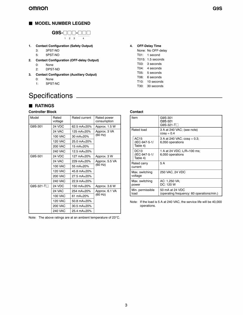
J MODEL NUMBER LEGEND
G9S-jjj-jjj1 2 3 4
1. Contact Configuration (Safety Output)3: 3PST-NO5: 5PST-NO
2. Contact Configuration (OFF-delay Output)0: None2: DPST-ND
3. Contact Configuration (Auxiliary Output)0: None1: SPST-NC
4. OFF-Delay TimeNone: No OFF-delayT01: 1 secondT015: 1.5 secondsT03: 3 secondsT04: 4 secondsT05: 5 secondsT06: 6 secondsT10: 10 secondsT30: 30 seconds
SpecificationsJ RATINGSController Block
Model Ratedvoltage
Rated current Rated powerconsumption
G9S-301 24 VDC 62.5 mA±20% Approx. 1.5 W
24 VAC 125 mA±20% Approx. 3 VA(60 H )100 VAC 30 mA±20%
pp(60 Hz)
120 VAC 25.0 mA±20%
200 VAC 15 mA±20%
240 VAC 12.5 mA±20%
G9S-501 24 VDC 127 mA±20% Approx. 3 W
24 VAC 229 mA±20% Approx. 5.5 VA(60 H )100 VAC 55 mA±20%
pp(60 Hz)
120 VAC 45.8 mA±20%
200 VAC 27.5 mA±20%
240 VAC 22.9 mA±20%
G9S-321-Tj 24 VDC 150 mA±20% Approx. 3.6 WG9S 3 j
24 VAC 254 mA±20% Approx. 6.1 VA(60 H )100 VAC 61 mA±20%
pp(60 Hz)
120 VAC 50.8 mA±20%
200 VAC 30.5 mA±20%
240 VAC 25.4 mA±20%
Note: The above ratings are at an ambient temperature of 23°C.
Contact
Item G9S-301G9S 501G9S-501G9S-321-Tj
Rated load 3 A at 240 VAC; (see note)cosφ = 0.4
AC15(IEC-947-5-1/Table 4)
3 A at 240 VAC; cosφ = 0.3;6,050 operations
DC13(IEC-947-5-1/Table 4)
1 A at 24 VDC; L/R=100 ms;6,050 operations
Rated carrycurrent
5 A
Max. switchingvoltage
250 VAC, 24 VDC
Max. switchingpower
AC: 1,250 VA;DC: 120 W
Min. permissibleload
50 mA at 24 VDC(operating frequency: 60 operations/min.)
Note: If the load is 5 A at 240 VAC, the service life will be 40,000operations.
G9S
4
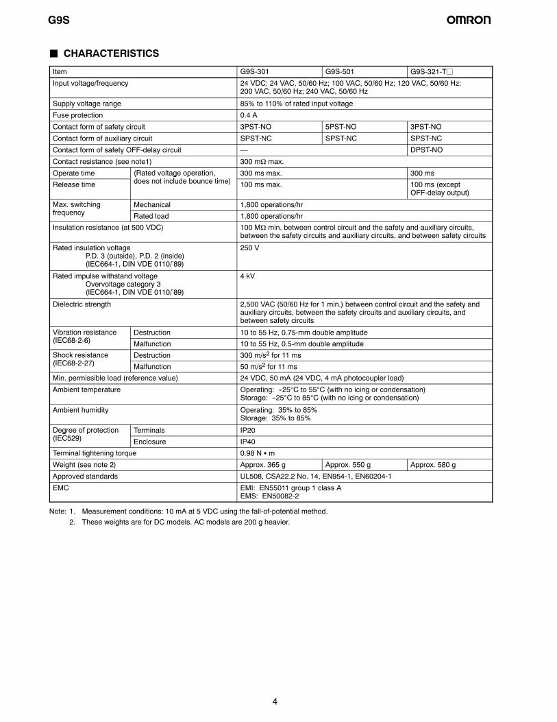
J CHARACTERISTICS
Item G9S-301 G9S-501 G9S-321-Tj
Input voltage/frequency 24 VDC; 24 VAC, 50/60 Hz; 100 VAC, 50/60 Hz; 120 VAC, 50/60 Hz;200 VAC, 50/60 Hz; 240 VAC, 50/60 Hz
Supply voltage range 85% to 110% of rated input voltage
Fuse protection 0.4 A
Contact form of safety circuit 3PST-NO 5PST-NO 3PST-NO
Contact form of auxiliary circuit SPST-NC SPST-NC SPST-NC
Contact form of safety OFF-delay circuit — DPST-NO
Contact resistance (see note1) 300 mΩ max.
Operate time (Rated voltage operation,d i l d b i )
300 ms max. 300 ms
Release time
( g p ,does not include bounce time) 100 ms max. 100 ms (except
OFF-delay output)
Max. switchingf
Mechanical 1,800 operations/hrgfrequency Rated load 1,800 operations/hr
Insulation resistance (at 500 VDC) 100 MΩ min. between control circuit and the safety and auxiliary circuits,between the safety circuits and auxiliary circuits, and between safety circuits
Rated insulation voltageP.D. 3 (outside), P.D. 2 (inside)(IEC664-1, DIN VDE 0110/’89)
250 V
Rated impulse withstand voltageOvervoltage category 3(IEC664-1, DIN VDE 0110/’89)
4 kV
Dielectric strength 2,500 VAC (50/60 Hz for 1 min.) between control circuit and the safety andauxiliary circuits, between the safety circuits and auxiliary circuits, andbetween safety circuits
Vibration resistance(IEC68 2 6)
Destruction 10 to 55 Hz, 0.75-mm double amplitude(IEC68-2-6) Malfunction 10 to 55 Hz, 0.5-mm double amplitude
Shock resistance(IEC68 2 27)
Destruction 300 m/s2 for 11 ms(IEC68-2-27) Malfunction 50 m/s2 for 11 ms
Min. permissible load (reference value) 24 VDC, 50 mA (24 VDC, 4 mA photocoupler load)
Ambient temperature Operating: --25°C to 55°C (with no icing or condensation)Storage: --25°C to 85°C (with no icing or condensation)
Ambient humidity Operating: 35% to 85%Storage: 35% to 85%
Degree of protection(IEC529)
Terminals IP20g p(IEC529) Enclosure IP40
Terminal tightening torque 0.98 N S m
Weight (see note 2) Approx. 365 g Approx. 550 g Approx. 580 g
Approved standards UL508, CSA22.2 No. 14, EN954-1, EN60204-1
EMC EMI: EN55011 group 1 class AEMS: EN50082-2
Note: 1. Measurement conditions: 10 mA at 5 VDC using the fall-of-potential method.2. These weights are for DC models. AC models are 200 g heavier.
G9S
5
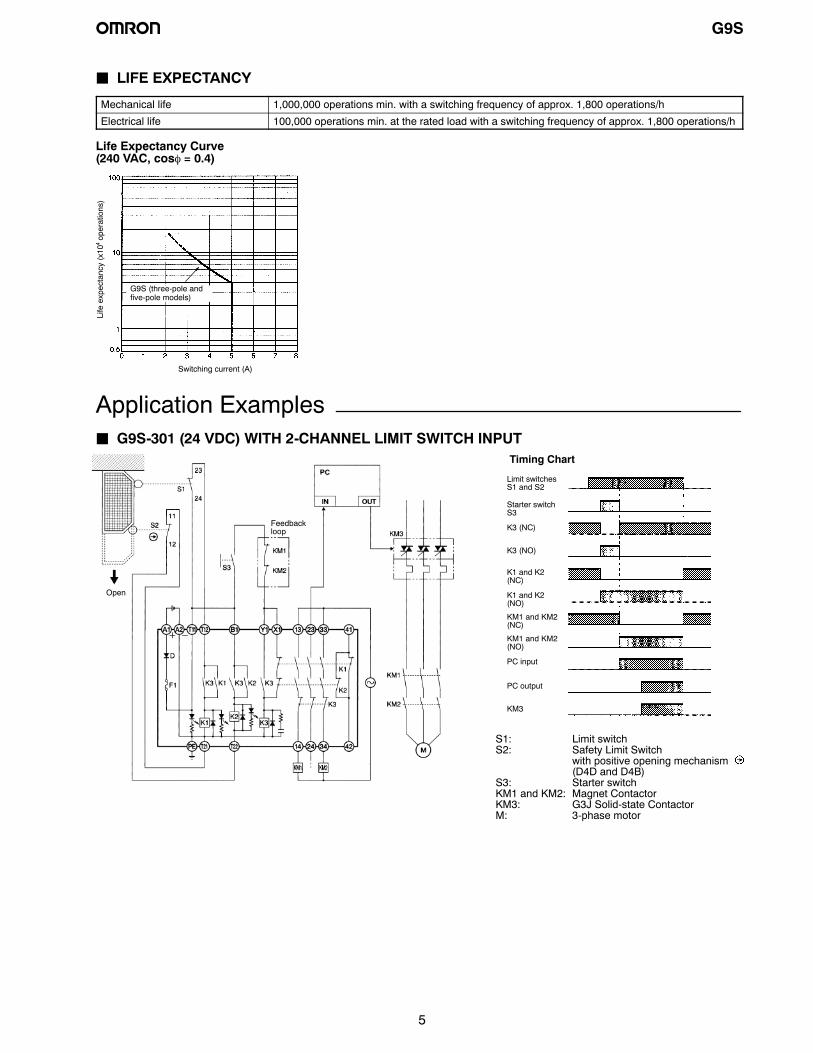
J LIFE EXPECTANCY
Mechanical life 1,000,000 operations min. with a switching frequency of approx. 1,800 operations/h
Electrical life 100,000 operations min. at the rated load with a switching frequency of approx. 1,800 operations/h
Life Expectancy Curve(240 VAC, cosφ = 0.4)
Switching current (A)
Lifeexpectancy
(x10
operations)
4
G9S (three-pole andfive-pole models)
Application ExamplesJ G9S-301 (24 VDC) WITH 2-CHANNEL LIMIT SWITCH INPUT
Feedbackloop
S1: Limit switchS2: Safety Limit Switch
with positive opening mechanism(D4D and D4B)
S3: Starter switchKM1 and KM2: Magnet ContactorKM3: G3J Solid-state ContactorM: 3-phase motor
Open
Limit switchesS1 and S2
Starter switchS3
K3 (NC)
K3 (NO)
K1 and K2(NC)
K1 and K2(NO)
KM1 and KM2(NC)
KM1 and KM2(NO)
PC input
PC output
KM3
Timing Chart
G9S
6
J G9S-501 (AC MODEL) WITH 2-CHANNEL LIMIT SWITCH INPUT
Feedbackloop
S1: Limit switchS2: Safety Limit Switch
with positive opening mechanism(D4D and D4B)
S3: Starter switchKM1 and KM2: Magnet ContactorM: 3-phase motor
Open
Timing Chart
Limit switchesS1 and S2
Starter switchS3
K3 (NC)
K3 (NO)
K1 and K2(NC)
K1 and K2(NO)
K4 and K5(NC)
K4 and K5(NO)
KM1 and KM2(NC)
KM1 and KM2(NO)
J G9S-321-Tj (24 VDC) WITH 2-CHANNEL LIMIT SWITCH INPUT
Feedback loop
S1: Limit switchS2: Safety Limit Switch
with positive opening mechanism(D4D and D4B)
S3: Starter switchKM1 and KM2: Magnet ContactorM: 3-phase motor
Operationinstruction
Motor controller
OFF-delaytimer
Open
Timing Chart
Limit switchesS1 and S2
Starter switchS3
K3 (NC)
K3 (NO)
K1 and K2(NC)
K1 and K2(NO)
K4 and K5(NC)
K4 and K5(NO)
KM1 and KM2(NC)
KM1 and KM2(NO)
Operationinstruction
Motor rotation
OFF-delay time
G9S
7
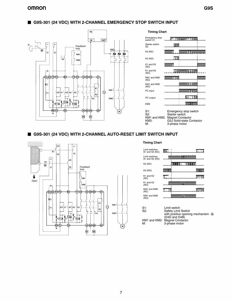
J G9S-301 (24 VDC) WITH 2-CHANNEL EMERGENCY STOP SWITCH INPUT
Feedbackloop
S1: Emergency stop switchS2: Starter switchKM1 and KM2: Magnet ContactorKM3: G3J Solid-state ContactorM: 3-phase motor
Emergency stopswitch S1
Starter switchS2
K3 (NC)
K3 (NO)
K1 and K2(NC)
K1 and K2(NO)
KM1 and KM2(NC)
KM1 and KM2(NO)
PC input
PC output
KM3
Timing Chart
J G9S-301 (24 VDC) WITH 2-CHANNEL AUTO-RESET LIMIT SWITCH INPUT
Feedbackloop
S1: Limit switchS2: Safety Limit Switch
with positive opening mechanism(D4D and D4B)
KM1 and KM2: Magnet ContactorM: 3-phase motor
Open
Limit switchesS1 and S2 (NC)
Limit switchesS1 and S2 (NO)
K3 (NC)
K3 (NO)
K1 and K2(NC)
K1 and K2(NO)
KM1 and KM2(NC)
KM1 and KM2(NO)
Timing Chart
G9S
8
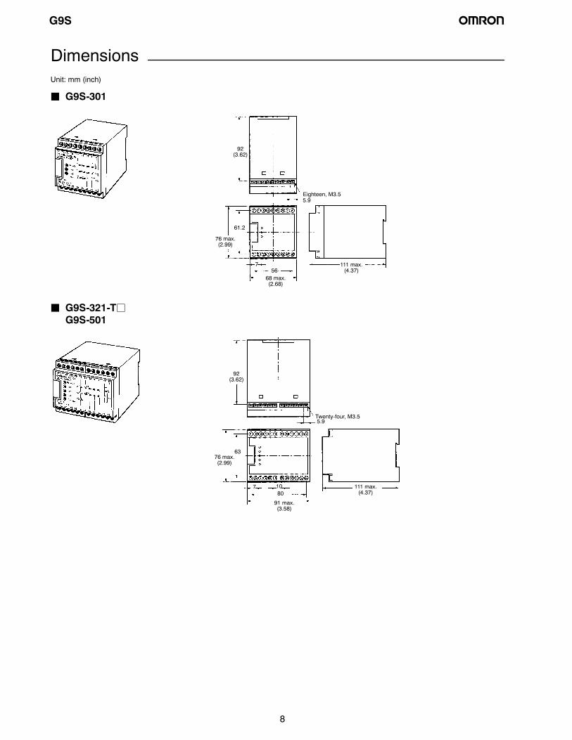
DimensionsUnit: mm (inch)
J G9S-301
76 max.(2.99)
68 max.(2.68)
Eighteen, M3.5
92(3.62)
111 max.(4.37)
61.2
56
5.9
7
J G9S-321-TjG9S-501
91 max.(3.58)
Twenty-four, M3.5
92(3.62)
76 max.(2.99)
111 max.(4.37)
63
5.9
80107
G9S
9
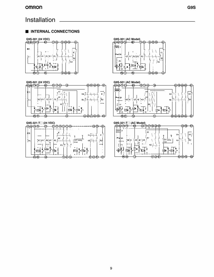
Installation
J INTERNAL CONNECTIONS
G9S-301 (24 VDC) G9S-301 (AC Model)
G9S-501 (24 VDC) G9S-501 (AC Model)
G9S-321-Tj (24 VDC) G9S-321-Tj (AC Model)
OFF-delaytimer
OFF-delaytimer
G9S
10
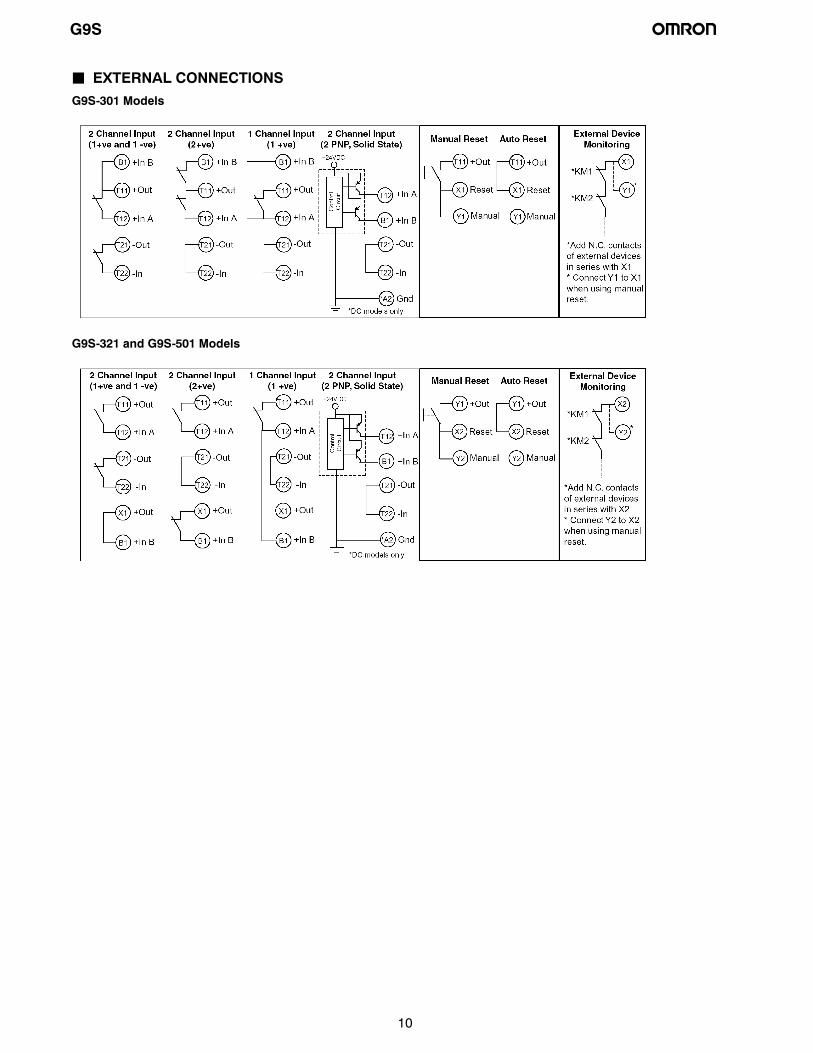
J EXTERNAL CONNECTIONSG9S-301 Models
G9S-321 and G9S-501 Models
G9S
11
Precautions
J WIRINGBe sure to turn off the G9S before wiring. Do not touch itsterminals while the power is turned on because the terminals arecharged and may cause an electric shock.
Use the following to wire the G9S.Strand wire: 0.75 to 1.5 mm2 16 to 18 AWGSteel wire: 1.0 to 1.5 mm2 16 to 18 AWG
Tighten each screw to a torque of 0.78 to 1.18 NSm (8 to12 kgfScm), or the G9S may malfunction or generate heat.
External inputs connected to T11 and T12 or T21 and T22 of theG9S-301 must be no-voltage contact inputs.
PE is a ground terminal.
When a machine is grounded at the positive, the PE terminalshould not be grounded.
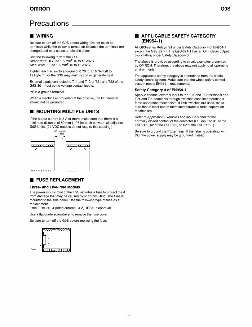
J MOUNTING MULTIPLE UNITSIf the output current is 3 A or more, make sure that there is aminimum distance of 50 mm (1.97 in) each between all adjacentG9S Units. (24-VDC models do not require this spacing.)
50 mm min.(1.97)
J FUSE REPLACEMENTThree- and Five-Pole ModelsThe power input circuit of the G9S includes a fuse to protect the itfrom damage that may be caused by short-circuiting. The fuse ismounted to the side panel. Use the following type of fuse as areplacement.Littel Fuse 218.4 (rated current 0.4 A), IEC127 approval.
Use a flat-blade screwdriver to remove the fuse cover.
Be sure to turn off the G9S before replacing the fuse.
Fuse
J APPLICABLE SAFETY CATEGORY(EN954-1)
All G9S-series Relays fall under Safety Category 4 of EN954-1except the G9S-321-T. The G9S-321-T has an OFF-delay outputblock falling under Safety Category 3.
The above is provided according to circuit examples presentedby OMRON. Therefore, the above may not apply to all operatingenvironments.
The applicable safety category is determined from the wholesafety control system. Make sure that the whole safety controlsystem meets EN954-1 requirements.
Safety Category 4 of EN954-1Apply 2-channel external input to the T11 and T12 terminals andT21 and T22 terminals through switches each incorporating aforce-separation mechanism. If limit switches are used, makesure that at least one of them incorporates a force-separationmechanism.
Refer to Application Examples and input a signal for thenormally-closed contact of the contactor (i.e., input to X1 of theG9S-301, X2 of the G9S-501, or X2 of the G9S-321-T).
Be sure to ground the PE terminal. If the relay is operating withDC, the power supply may be grounded instead.

OMRON ON-LINEGlobal - http://www.omron.comUSA - http://www.omron.com/oeiCanada - http://www.omron.ca
ALL DIMENSIONS SHOWN ARE IN MILLIMETERS. To convert millimeters into inches, divide by 25.4
Cat. No. GC SAFETY-2 Printed in USA
OMRON CANADA, INC.885 Milner AvenueToronto, Ontario M1B 5V8
416-286-6465
OMRON ELECTRONICS LLCOne Commerce DriveSchaumburg, IL 60173
847-843-7900For US technical support or other inquiries:
800-556-6766
2/03 Specifications subject to change without notice