Embed Size (px)
Citation preview

Safety Relay ModuleUser's Manual
-QS90SR2SP-Q-QS90SR2SN-Q-QS90SR2SP-CC-QS90SR2SN-CC-QS90SR2SP-EX-QS90SR2SN-EX


SAFETY PRECAUTIONS(Always read these instructions before using this equipment.)
Before using the product, please read this manual, the relevant manuals introduced in this manual,
standard programmable controller manuals, and the safety standards carefully and pay full attention to
safety to handle the product correctly.
In this manual, the safety instructions are ranked as " WARNING" and " CAUTION".
Note that the CAUTION level may lead to a serious consequence according to the circumstances.
Always follow the instructions of both levels because they are important to personal safety.
Please save this manual to make it accessible when required and always forward it to the end user.
[Design Precautions]
WARNING
● A safety relay module turns OFF all outputs by safety input or a failure of external power supply.
Create an external circuit to securely stop the power of hazard by turning OFF the outputs.
Incorrect configuration may result in an accident.
● When overcurrent due to such as load short-circuit or load current exceeding the rating flows for a
long time, it may cause smoke or fire. To prevent this, create external safety circuit such as a fuse.
● Create short-circuit current protection for a safety relay and a protection circuit such as a fuse and
breaker, outside a safety relay module.
● To inhibit a restart without manual operation after safety function of the safety relay module was
performed and outputs were turned OFF, create reset start-up circuit using such as a reset switch
outside the safety relay module.
● The safety relay module may consume excessive current due to a failure. If this occurs, the DC
power supply connected to the safety power supply part (+24V (SAFETY) and 24G (SAFETY)
terminals) of the module detects an overcurrent and may shut off the output. To the DC power supply
connected to the safety relay module, connect only the equipment and the devices that will not affect
the system even if they are simultaneously stopped due to power-off.
● Use an extension module whose input type is the same as that of the main module. The modules of
different input types (input P and N types) cannot be connected.
WARNING
CAUTION
Indicates that incorrect handling may cause hazardous conditions,
resulting in death or severe injury.
Indicates that incorrect handling may cause hazardous conditions,
resulting in minor or moderate injury or property damage.
A - 1
[Design Precautions]
[Installation Precautions]
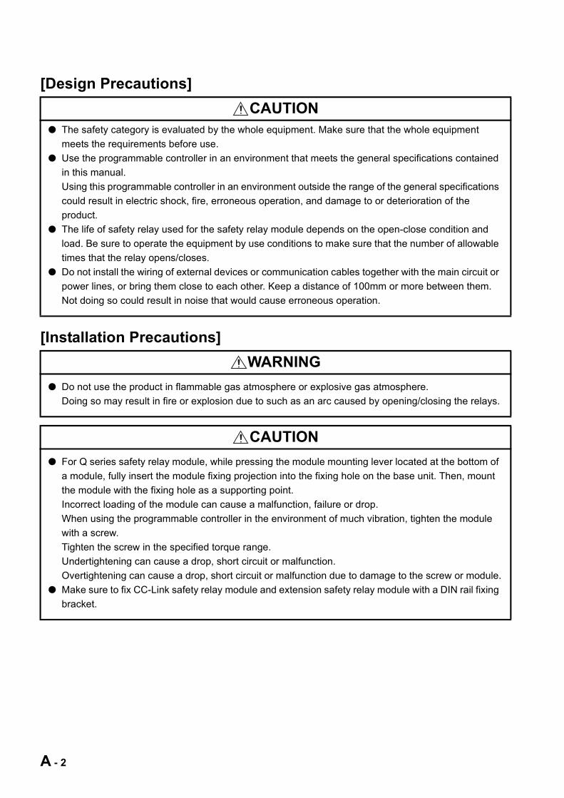
CAUTION● The safety category is evaluated by the whole equipment. Make sure that the whole equipment
meets the requirements before use.
● Use the programmable controller in an environment that meets the general specifications contained
in this manual.
Using this programmable controller in an environment outside the range of the general specifications
could result in electric shock, fire, erroneous operation, and damage to or deterioration of the
product.
● The life of safety relay used for the safety relay module depends on the open-close condition and
load. Be sure to operate the equipment by use conditions to make sure that the number of allowable
times that the relay opens/closes.
● Do not install the wiring of external devices or communication cables together with the main circuit or
power lines, or bring them close to each other. Keep a distance of 100mm or more between them.
Not doing so could result in noise that would cause erroneous operation.
WARNING
● Do not use the product in flammable gas atmosphere or explosive gas atmosphere.
Doing so may result in fire or explosion due to such as an arc caused by opening/closing the relays.
CAUTION
● For Q series safety relay module, while pressing the module mounting lever located at the bottom of
a module, fully insert the module fixing projection into the fixing hole on the base unit. Then, mount
the module with the fixing hole as a supporting point.
Incorrect loading of the module can cause a malfunction, failure or drop.
When using the programmable controller in the environment of much vibration, tighten the module
with a screw.
Tighten the screw in the specified torque range.
Undertightening can cause a drop, short circuit or malfunction.
Overtightening can cause a drop, short circuit or malfunction due to damage to the screw or module.
● Make sure to fix CC-Link safety relay module and extension safety relay module with a DIN rail fixing
bracket.
A - 2
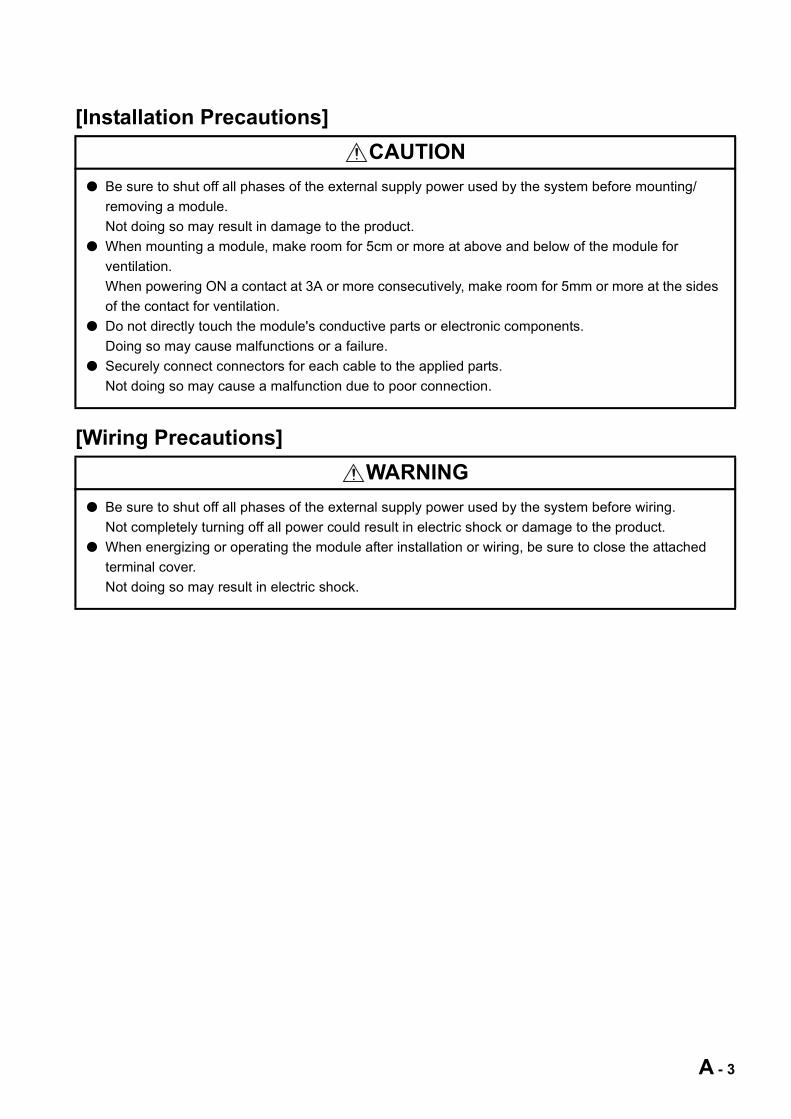
[Installation Precautions]
[Wiring Precautions]
CAUTION
● Be sure to shut off all phases of the external supply power used by the system before mounting/
removing a module.
Not doing so may result in damage to the product.
● When mounting a module, make room for 5cm or more at above and below of the module for
ventilation.
When powering ON a contact at 3A or more consecutively, make room for 5mm or more at the sides
of the contact for ventilation.
● Do not directly touch the module's conductive parts or electronic components.
Doing so may cause malfunctions or a failure.
● Securely connect connectors for each cable to the applied parts.
Not doing so may cause a malfunction due to poor connection.
WARNING
● Be sure to shut off all phases of the external supply power used by the system before wiring.
Not completely turning off all power could result in electric shock or damage to the product.
● When energizing or operating the module after installation or wiring, be sure to close the attached
terminal cover.
Not doing so may result in electric shock.
A - 3
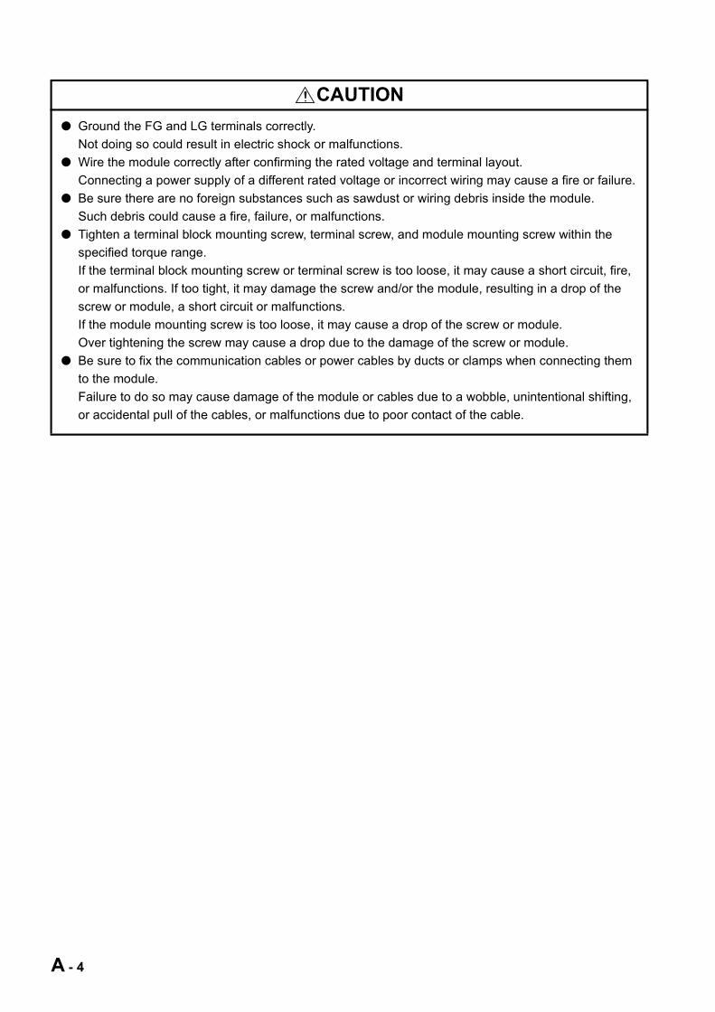
CAUTION
● Ground the FG and LG terminals correctly.
Not doing so could result in electric shock or malfunctions.
● Wire the module correctly after confirming the rated voltage and terminal layout.
Connecting a power supply of a different rated voltage or incorrect wiring may cause a fire or failure.
● Be sure there are no foreign substances such as sawdust or wiring debris inside the module.
Such debris could cause a fire, failure, or malfunctions.
● Tighten a terminal block mounting screw, terminal screw, and module mounting screw within the
specified torque range.
If the terminal block mounting screw or terminal screw is too loose, it may cause a short circuit, fire,
or malfunctions. If too tight, it may damage the screw and/or the module, resulting in a drop of the
screw or module, a short circuit or malfunctions.
If the module mounting screw is too loose, it may cause a drop of the screw or module.
Over tightening the screw may cause a drop due to the damage of the screw or module.
● Be sure to fix the communication cables or power cables by ducts or clamps when connecting them
to the module.
Failure to do so may cause damage of the module or cables due to a wobble, unintentional shifting,
or accidental pull of the cables, or malfunctions due to poor contact of the cable.
A - 4
[Wiring Precautions]
[Startup and Maintenance Precautions]
CAUTION
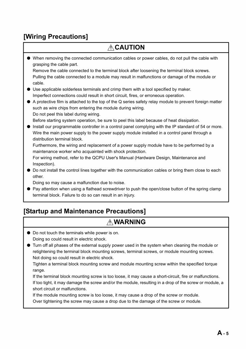
● When removing the connected communication cables or power cables, do not pull the cable with
grasping the cable part.
Remove the cable connected to the terminal block after loosening the terminal block screws.
Pulling the cable connected to a module may result in malfunctions or damage of the module or
cable.
● Use applicable solderless terminals and crimp them with a tool specified by maker.
Imperfect connections could result in short circuit, fires, or erroneous operation.
● A protective film is attached to the top of the Q series safety relay module to prevent foreign matter
such as wire chips from entering the module during wiring.
Do not peel this label during wiring.
Before starting system operation, be sure to peel this label because of heat dissipation.
● Install our programmable controller in a control panel complying with the IP standard of 54 or more.
Wire the main power supply to the power supply module installed in a control panel through a
distribution terminal block.
Furthermore, the wiring and replacement of a power supply module have to be performed by a
maintenance worker who acquainted with shock protection.
For wiring method, refer to the QCPU User's Manual (Hardware Design, Maintenance and
Inspection).
● Do not install the control lines together with the communication cables or bring them close to each
other.
Doing so may cause a malfunction due to noise.
● Pay attention when using a flathead screwdriver to push the open/close button of the spring clamp
terminal block. Failure to do so can result in an injury.
WARNING
● Do not touch the terminals while power is on.
Doing so could result in electric shock.
● Turn off all phases of the external supply power used in the system when cleaning the module or
retightening the terminal block mounting screws, terminal screws, or module mounting screws.
Not doing so could result in electric shock.
Tighten a terminal block mounting screw and module mounting screw within the specified torque
range.
If the terminal block mounting screw is too loose, it may cause a short-circuit, fire or malfunctions.
If too tight, it may damage the screw and/or the module, resulting in a drop of the screw or module, a
short circuit or malfunctions.
If the module mounting screw is too loose, it may cause a drop of the screw or module.
Over tightening the screw may cause a drop due to the damage of the screw or module.
A - 5
[Startup and Maintenance Precautions]
[Disposal Precautions]
CAUTION
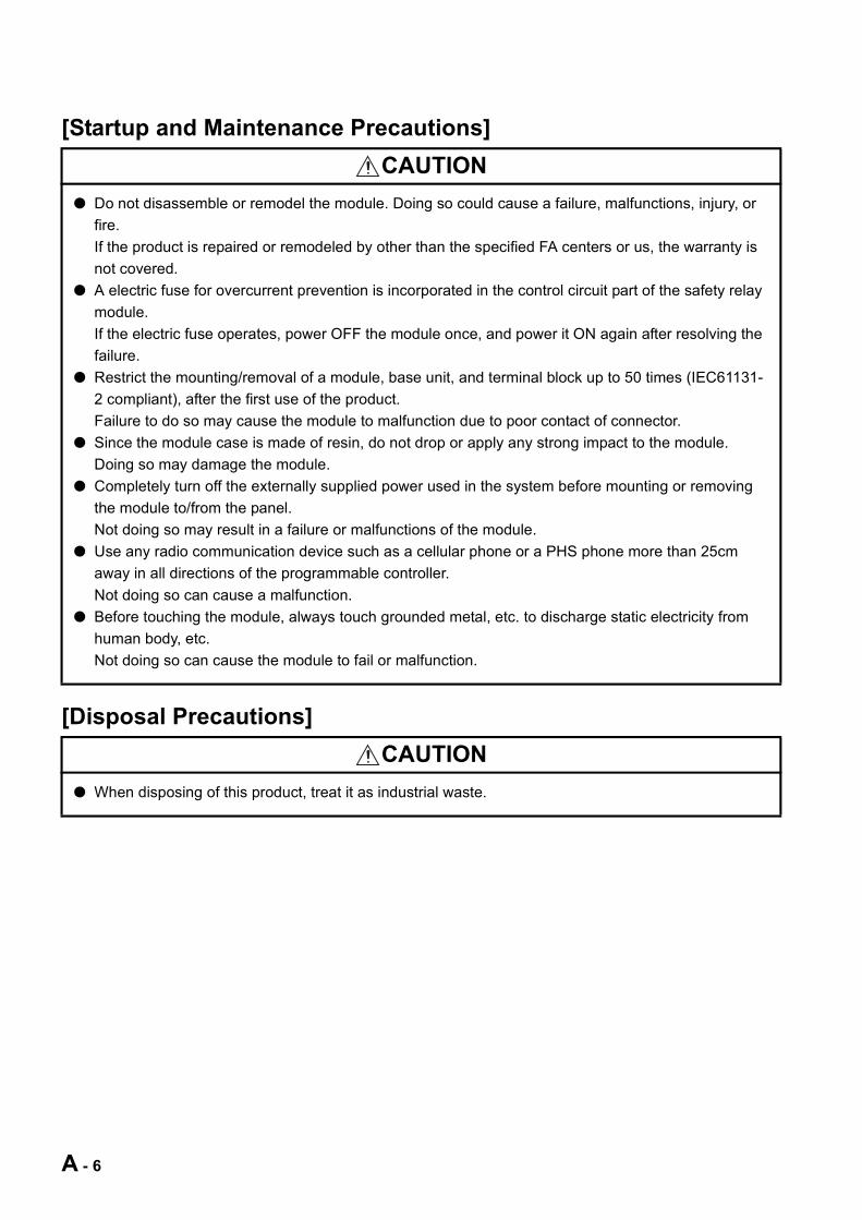
● Do not disassemble or remodel the module. Doing so could cause a failure, malfunctions, injury, or
fire.
If the product is repaired or remodeled by other than the specified FA centers or us, the warranty is
not covered.
● A electric fuse for overcurrent prevention is incorporated in the control circuit part of the safety relay
module.
If the electric fuse operates, power OFF the module once, and power it ON again after resolving the
failure.
● Restrict the mounting/removal of a module, base unit, and terminal block up to 50 times (IEC61131-
2 compliant), after the first use of the product.
Failure to do so may cause the module to malfunction due to poor contact of connector.
● Since the module case is made of resin, do not drop or apply any strong impact to the module.
Doing so may damage the module.
● Completely turn off the externally supplied power used in the system before mounting or removing
the module to/from the panel.
Not doing so may result in a failure or malfunctions of the module.
● Use any radio communication device such as a cellular phone or a PHS phone more than 25cm
away in all directions of the programmable controller.
Not doing so can cause a malfunction.
● Before touching the module, always touch grounded metal, etc. to discharge static electricity from
human body, etc.
Not doing so can cause the module to fail or malfunction.
CAUTION
● When disposing of this product, treat it as industrial waste.
A - 6
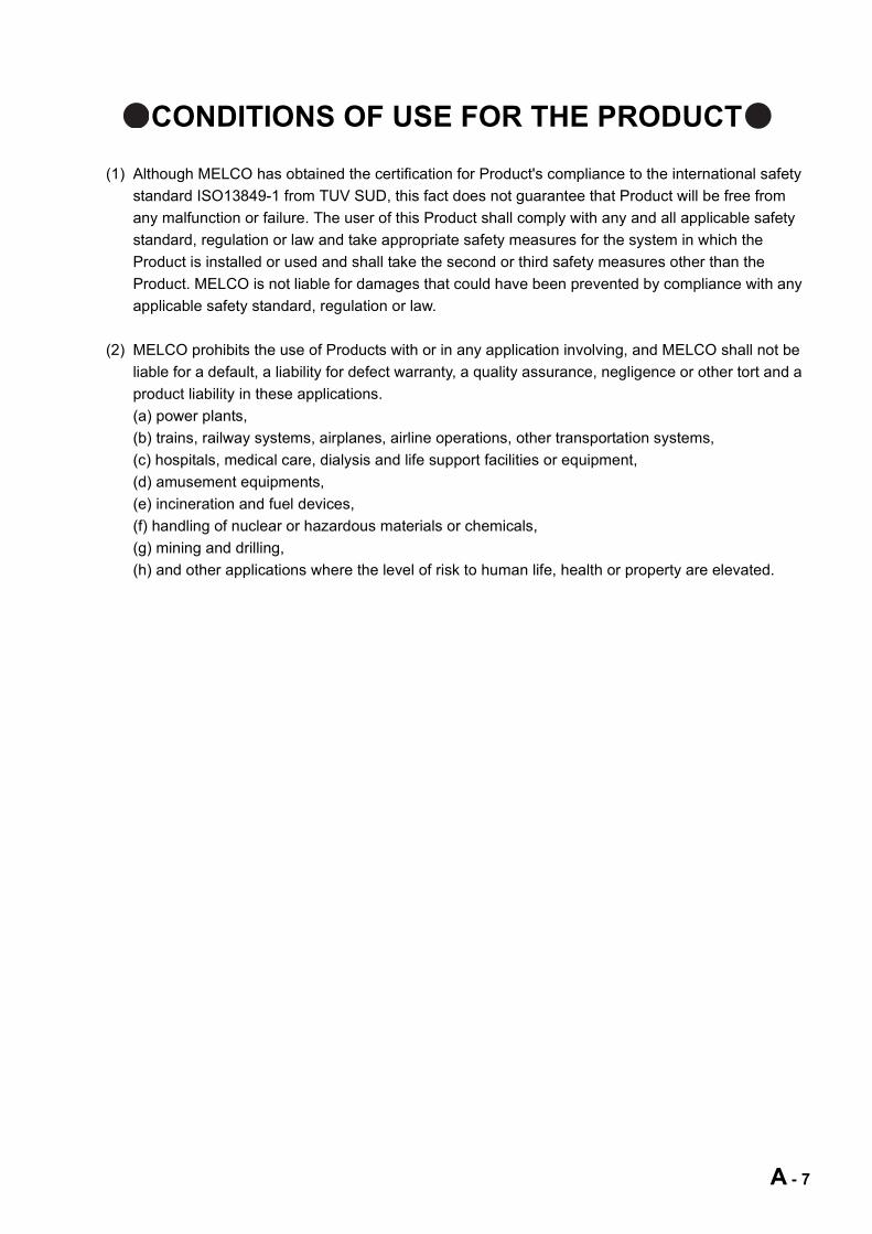
CONDITIONS OF USE FOR THE PRODUCT
(1) Although MELCO has obtained the certification for Product's compliance to the international safety
standard ISO13849-1 from TUV SUD, this fact does not guarantee that Product will be free from
any malfunction or failure. The user of this Product shall comply with any and all applicable safety
standard, regulation or law and take appropriate safety measures for the system in which the
Product is installed or used and shall take the second or third safety measures other than the
Product. MELCO is not liable for damages that could have been prevented by compliance with any
applicable safety standard, regulation or law.
(2) MELCO prohibits the use of Products with or in any application involving, and MELCO shall not be
liable for a default, a liability for defect warranty, a quality assurance, negligence or other tort and a
product liability in these applications.
(a) power plants,
(b) trains, railway systems, airplanes, airline operations, other transportation systems,
(c) hospitals, medical care, dialysis and life support facilities or equipment,
(d) amusement equipments,
(e) incineration and fuel devices,
(f) handling of nuclear or hazardous materials or chemicals,
(g) mining and drilling,
(h) and other applications where the level of risk to human life, health or property are elevated.
A - 7

REVISIONS
* The manual number is given on the bottom left of the back cover.
Japanese Manual Version SH-080745-G
2008 MITSUBISHI ELECTRIC CORPORATION
Print date *Manual number Revision
Apr., 2008 SH(NA)-080746ENG-A First edition
Jun., 2008 SH(NA)-080746ENG-B
COMPLIANCE WITH THE EMC AND LOW VOLTAGE DIRECTIVES,
Section 5.1.1, 5.1.4, 5.2.1, 5.3.1, 6.1.2, 6.2.2, 6.3.2
Nov., 2008 SH(NA)-080746ENG-C
Section 3.1, 3.2.2, 3.4.1, 5.4.1, 5.4.7
Jan., 2010 SH(NA)-080746ENG-D
Section 2.2, 3.1, 3.2.1, 3.2.2, 3.3.1, 3.3.2, 3.4.1, 3.4.2, 5.4.1, 5.4.7
Apr., 2015 SH(NA)-080746ENG-E
CONDITIONS OF USE FOR THE PRODUCT, Section 1.1, 2.3, 2.4
SAFETY PRECAUTIONS, ABOUT MANUALS, COMPLIANCE WITH THE EMC,
LOW VOLTAGE, AND MACHINERY DIRECTIVES, Section 1.3, 1.4, 2.2, 2.4,
3.1, 3.2.1, 3.3.1, 3.3.2, 3.4.2, 3.5, 3.6, Chapter 4, Section 4.3, 4.5, 5.1.1, 5.1.2,
5.1.3, 5.1.4, 5.2.1, 5.2.3, 5.2.4, 5.3.1, 5.3.2, 5.3.3, 5.4.1, 5.4.2, 5.4.3, 5.4.6, 5.4.7,
6.1.1, 6.1.2, 6.2.1, 6.2.2, 6.3.1, 6.3.2, APPENDIX 1.1
Dec., 2016 SH(NA)-080746ENG-F
COMPLIANCE WITH THE EMC, LOW VOLTAGE, AND MACHINERY
DIRECTIVES, Section 1.3, 2.4
This manual confers no industrial property rights or any rights of any other kind, nor does it confer any licenses.
Mitsubishi Electric Corporation cannot be held responsible for any problems involving industrial property rights which may
occur as a result of using the contents noted in this manual.
Partial corrections
Partial corrections
Partial corrections
Addition
Partial corrections
Partial corrections
A - 8
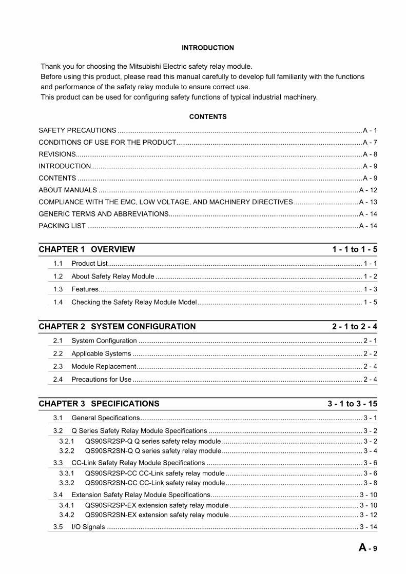
SAFETY PRECAUTIONS .................................................................................................................................A - 1
CONDITIONS OF USE FOR THE PRODUCT..................................................................................................A - 7
REVISIONS.......................................................................................................................................................A - 8
INTRODUCTION...............................................................................................................................................A - 9
CONTENTS ......................................................................................................................................................A - 9
ABOUT MANUALS .........................................................................................................................................A - 12
COMPLIANCE WITH THE EMC, LOW VOLTAGE, AND MACHINERY DIRECTIVES ..................................A - 13
GENERIC TERMS AND ABBREVIATIONS....................................................................................................A - 14
PACKING LIST ...............................................................................................................................................A - 14
CHAPTER 1 OVERVIEW 1 - 1 to 1 - 5
1.1 Product List...................................................................................................................................... 1 - 1
1.2 About Safety Relay Module ............................................................................................................. 1 - 2
1.3 Features........................................................................................................................................... 1 - 3
1.4 Checking the Safety Relay Module Model....................................................................................... 1 - 5
CHAPTER 2 SYSTEM CONFIGURATION 2 - 1 to 2 - 4
2.1 System Configuration ...................................................................................................................... 2 - 1
2.2 Applicable Systems ......................................................................................................................... 2 - 2
2.3 Module Replacement....................................................................................................................... 2 - 4
2.4 Precautions for Use ......................................................................................................................... 2 - 4
CHAPTER 3 SPECIFICATIONS 3 - 1 to 3 - 15
3.1 General Specifications..................................................................................................................... 3 - 1
3.2 Q Series Safety Relay Module Specifications ................................................................................. 3 - 2
3.2.1 QS90SR2SP-Q Q series safety relay module .......................................................................... 3 - 2
3.2.2 QS90SR2SN-Q Q series safety relay module.......................................................................... 3 - 4
3.3 CC-Link Safety Relay Module Specifications .................................................................................. 3 - 6
3.3.1 QS90SR2SP-CC CC-Link safety relay module ........................................................................ 3 - 6
3.3.2 QS90SR2SN-CC CC-Link safety relay module........................................................................ 3 - 8
3.4 Extension Safety Relay Module Specifications.............................................................................. 3 - 10
3.4.1 QS90SR2SP-EX extension safety relay module .................................................................... 3 - 10
3.4.2 QS90SR2SN-EX extension safety relay module.................................................................... 3 - 12
3.5 I/O Signals ..................................................................................................................................... 3 - 14
INTRODUCTION
Thank you for choosing the Mitsubishi Electric safety relay module.
Before using this product, please read this manual carefully to develop full familiarity with the functions
and performance of the safety relay module to ensure correct use.
This product can be used for configuring safety functions of typical industrial machinery.
CONTENTS
A - 9
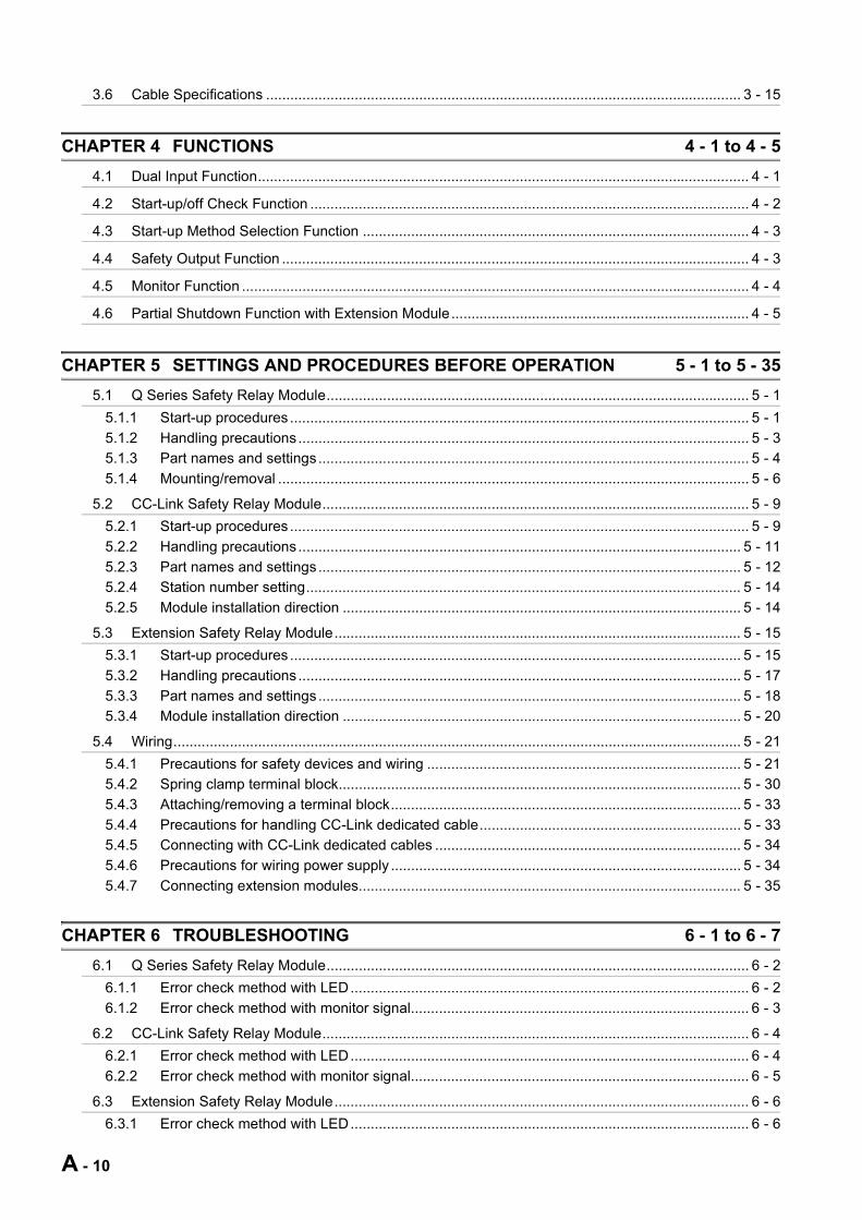
3.6 Cable Specifications ...................................................................................................................... 3 - 15
CHAPTER 4 FUNCTIONS 4 - 1 to 4 - 5
4.1 Dual Input Function.......................................................................................................................... 4 - 1
4.2 Start-up/off Check Function ............................................................................................................. 4 - 2
4.3 Start-up Method Selection Function ................................................................................................ 4 - 3
4.4 Safety Output Function .................................................................................................................... 4 - 3
4.5 Monitor Function .............................................................................................................................. 4 - 4
4.6 Partial Shutdown Function with Extension Module.......................................................................... 4 - 5
CHAPTER 5 SETTINGS AND PROCEDURES BEFORE OPERATION 5 - 1 to 5 - 35
5.1 Q Series Safety Relay Module......................................................................................................... 5 - 1
5.1.1 Start-up procedures .................................................................................................................. 5 - 1
5.1.2 Handling precautions................................................................................................................ 5 - 3
5.1.3 Part names and settings........................................................................................................... 5 - 4
5.1.4 Mounting/removal ..................................................................................................................... 5 - 6
5.2 CC-Link Safety Relay Module.......................................................................................................... 5 - 9
5.2.1 Start-up procedures .................................................................................................................. 5 - 9
5.2.2 Handling precautions.............................................................................................................. 5 - 11
5.2.3 Part names and settings......................................................................................................... 5 - 12
5.2.4 Station number setting............................................................................................................ 5 - 14
5.2.5 Module installation direction ................................................................................................... 5 - 14
5.3 Extension Safety Relay Module..................................................................................................... 5 - 15
5.3.1 Start-up procedures ................................................................................................................ 5 - 15
5.3.2 Handling precautions.............................................................................................................. 5 - 17
5.3.3 Part names and settings......................................................................................................... 5 - 18
5.3.4 Module installation direction ................................................................................................... 5 - 20
5.4 Wiring............................................................................................................................................. 5 - 21
5.4.1 Precautions for safety devices and wiring .............................................................................. 5 - 21
5.4.2 Spring clamp terminal block.................................................................................................... 5 - 30
5.4.3 Attaching/removing a terminal block....................................................................................... 5 - 33
5.4.4 Precautions for handling CC-Link dedicated cable................................................................. 5 - 33
5.4.5 Connecting with CC-Link dedicated cables ............................................................................ 5 - 34
5.4.6 Precautions for wiring power supply ....................................................................................... 5 - 34
5.4.7 Connecting extension modules............................................................................................... 5 - 35
CHAPTER 6 TROUBLESHOOTING 6 - 1 to 6 - 7
6.1 Q Series Safety Relay Module......................................................................................................... 6 - 2
6.1.1 Error check method with LED................................................................................................... 6 - 2
6.1.2 Error check method with monitor signal.................................................................................... 6 - 3
6.2 CC-Link Safety Relay Module.......................................................................................................... 6 - 4
6.2.1 Error check method with LED................................................................................................... 6 - 4
6.2.2 Error check method with monitor signal.................................................................................... 6 - 5
6.3 Extension Safety Relay Module....................................................................................................... 6 - 6
6.3.1 Error check method with LED................................................................................................... 6 - 6
A - 10
6.3.2 Error check method with monitor signal ................................................................................... 6 - 7
APPENDIX App - 1 to App - 4
Appendix 1 External Dimensions.........................................................................................................App - 1
Appendix 1.1 Q series safety relay module....................................................................................App - 1
Appendix 1.2 CC-Link safety relay module ....................................................................................App - 2
Appendix 1.3 Extension safety relay module .................................................................................App - 3
A - 11
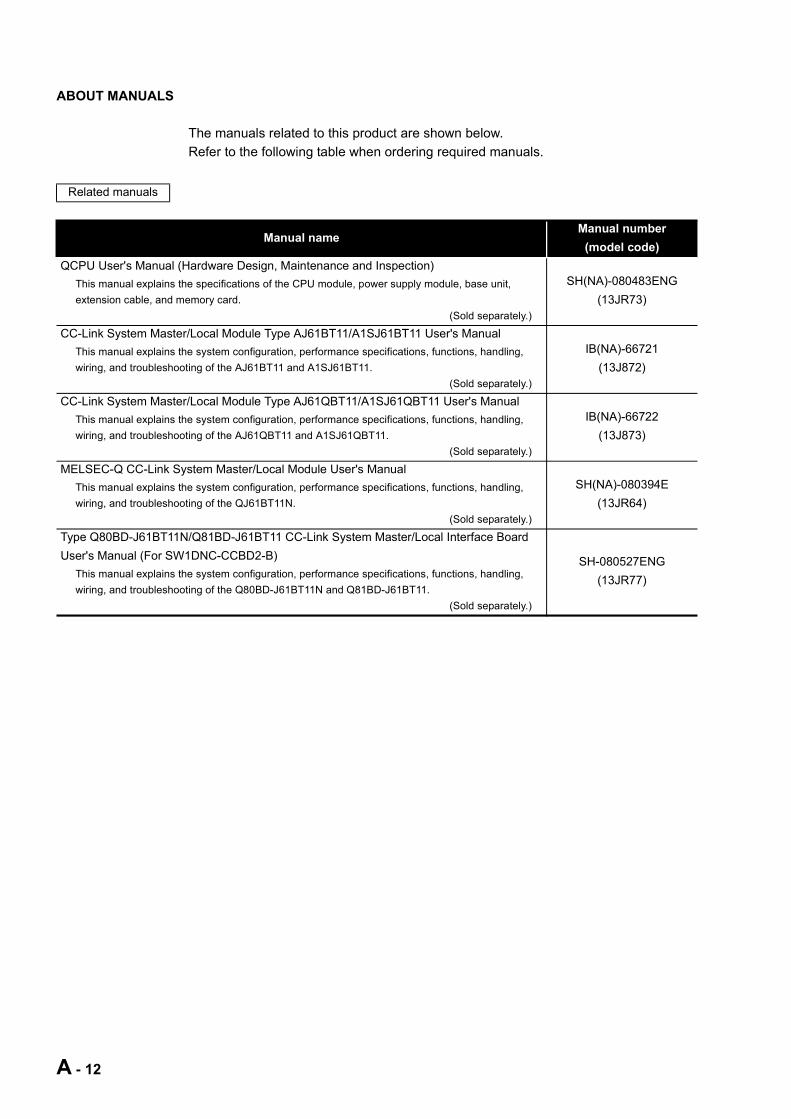
ABOUT MANUALS
The manuals related to this product are shown below.
Refer to the following table when ordering required manuals.
Related manuals
Manual nameManual number
(model code)
QCPU User's Manual (Hardware Design, Maintenance and Inspection)
This manual explains the specifications of the CPU module, power supply module, base unit,
extension cable, and memory card.
(Sold separately.)
SH(NA)-080483ENG
(13JR73)
CC-Link System Master/Local Module Type AJ61BT11/A1SJ61BT11 User's Manual
This manual explains the system configuration, performance specifications, functions, handling,
wiring, and troubleshooting of the AJ61BT11 and A1SJ61BT11.
(Sold separately.)
IB(NA)-66721
(13J872)
CC-Link System Master/Local Module Type AJ61QBT11/A1SJ61QBT11 User's Manual
This manual explains the system configuration, performance specifications, functions, handling,
wiring, and troubleshooting of the AJ61QBT11 and A1SJ61QBT11.
(Sold separately.)
IB(NA)-66722
(13J873)
MELSEC-Q CC-Link System Master/Local Module User's Manual
This manual explains the system configuration, performance specifications, functions, handling,
wiring, and troubleshooting of the QJ61BT11N.
(Sold separately.)
SH(NA)-080394E
(13JR64)
Type Q80BD-J61BT11N/Q81BD-J61BT11 CC-Link System Master/Local Interface Board
User's Manual (For SW1DNC-CCBD2-B)
This manual explains the system configuration, performance specifications, functions, handling,
wiring, and troubleshooting of the Q80BD-J61BT11N and Q81BD-J61BT11.
(Sold separately.)
SH-080527ENG
(13JR77)
A - 12

COMPLIANCE WITH THE EMC, LOW VOLTAGE, AND MACHINERY DIRECTIVES
(1) Method of ensuring complianceTo ensure that Mitsubishi programmable controllers maintain EMC, Low Voltage, and
Machinery Directives when incorporated into other machinery or equipment, certain
measures may be necessary. Please refer to one of the following manuals.
• User's manual for the CPU module used
• Safety Guidelines
(This manual is included with the base unit.)
The CE mark on the side of the programmable controller indicates compliance with
EMC, Low Voltage, and Machinery Directives.
(a) Sales representative in EU member states
The sales representative in EU member states is:
Company: MITSUBISHI ELECTRIC EUROPE B.V.
Address: Mitsubishi-Electric-Platz 1, 40882 Ratingen, Germany
(2) Additional measuresThis product complies with the EMC, Low Voltage, and Machinery Directives. Before
using this product, please read this manual, the relevant manuals, the manuals for
standard programmable controllers, and the safety standards carefully and pay full
attention to safety to handle the product correctly.
The descriptions are based on the requirements of the Directives and the harmonized
standards. However, they do not guarantee that the entire machinery constructed
according to the descriptions complies with the EMC, Low Voltage, and Machinery
Directives.
The manufacture of the machinery must determine the testing method for compliance
and declare conformity to the EMC, Low Voltage, and Machinery Directives.
A - 13
A - 14
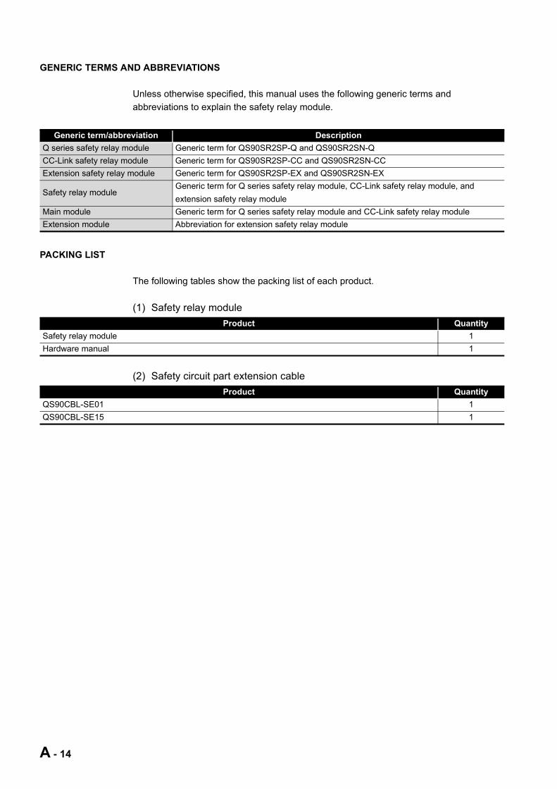
GENERIC TERMS AND ABBREVIATIONS
Unless otherwise specified, this manual uses the following generic terms and
abbreviations to explain the safety relay module.
PACKING LIST
The following tables show the packing list of each product.
(1) Safety relay module
(2) Safety circuit part extension cable
Generic term/abbreviation Description
Q series safety relay module Generic term for QS90SR2SP-Q and QS90SR2SN-Q
CC-Link safety relay module Generic term for QS90SR2SP-CC and QS90SR2SN-CC
Extension safety relay module Generic term for QS90SR2SP-EX and QS90SR2SN-EX
Safety relay moduleGeneric term for Q series safety relay module, CC-Link safety relay module, and
extension safety relay module
Main module Generic term for Q series safety relay module and CC-Link safety relay module
Extension module Abbreviation for extension safety relay module
Product Quantity
Safety relay module 1
Hardware manual 1
Product Quantity
QS90CBL-SE01 1
QS90CBL-SE15 1

1 OVERVIEW
1
OV
ER
VIE
W
2
SY
ST
EM
C
ON
FIG
UR
AT
ION
3
SP
EC
IFIC
AT
ION
S
4
FU
NC
TIO
NS
5
SE
TT
ING
S A
ND
P
RO
CE
DU
RE
S B
EF
OR
E
OP
ER
AT
ION
6
TR
OU
BL
ES
HO
OT
ING
AP
PE
ND
IX
CHAPTER 1 OVERVIEW
This manual explains specifications, handling, and wiring methods of the safety relay
module.
1.1 Product List
Table 1.1 Product list
Product name Model name Description
Q series safety relay module
QS90SR2SP-QA safety relay module mounted on a MELSEC-Q series base unit
Input P type (Dual input with positive commons)
QS90SR2SN-Q
A safety relay module mounted on a MELSEC-Q series base unit
Input N type (Dual input with positive common and negative
common)
CC-Link safety relay module
QS90SR2SP-CCA safety relay module connected to the CC-Link network
Input P type (Dual input with positive commons)
QS90SR2SN-CC
A safety relay module connected to the CC-Link network
Input N type (Dual input with positive common and negative
common)
Extension safety relay module
QS90SR2SP-EXAn extension safety relay module
Input P type (Dual input with positive commons)
QS90SR2SN-EX
An extension safety relay module
Input N type (Dual input with positive common and negative
common)
1.1 Product List
1 - 1

1 OVERVIEW
1.2 About Safety Relay Module
The safety relay module achieves basic safety functions for emergency stop only by
wiring, without programming.
It is safety check type module whose output does not turn ON until all conditions of the
safety input (normally closed contact), off check input (normally closed contact), and start-
up switch (normally open contact) are met.
Using the module helps to reduce the man-hour taken for configuring a safety check
system.
Figure 1.1 Safety relay module
Safety input
Start-up input
Safety input(such as emergency stop switch and light curtain)
Off check input
Start-up switch
Safety relay module
Such as electromagnetic switch
1 - 2 1.2 About Safety Relay Module

1 OVERVIEW
1
OV
ER
VIE
W
2
SY
ST
EM
C
ON
FIG
UR
AT
ION
3
SP
EC
IFIC
AT
ION
S
4
FU
NC
TIO
NS
5
SE
TT
ING
S A
ND
P
RO
CE
DU
RE
S B
EF
OR
E
OP
ER
AT
ION
6
TR
OU
BL
ES
HO
OT
ING
AP
PE
ND
IX
1.3 Features
This section explains features of the safety relay module.
(1) Obtaining the highest level of safety approvalThe safety relay module obtained the highest safety approval (Category 4 of EN
ISO13849-1/performance level E) that the programmable controller can be gained
(In some conditions, Category 3/performance level D can be gained).
A system ensuring higher safety can be configured.
(2) Category 3 and Category 4 compliantA system complying with Category 3 or Category 4 of EN ISO13849-1 can be
configured depending on the safety input device to be connected and rated current.
(3) Safety standardsUse this product according to the following safety standards.
(4) Monitoring safety control with the MELSEC-Q series is possible.Mounting/connecting the safety relay module on/to existing MELSEC-Q series
programmable controller allows monitoring operating status of the whole safety relay
module and error status of the module.
Table 1.2 Conditions for complying with each category
Condition
Safety input device to be
connectedRated current
Contact-type
input device
Type 4 light
curtain5.0A max. 3.6A max.
Dual input with positive
commons
(Input P type)
Category 3 Category 4 Category 3Category 3 or
Category 4
Dual input with positive
common and negative common
(Input N type)
Category 4Not
connectableCategory 3 Category 4
Table 1.3 Safety standards
Region Standard
Global ISO13849-1: 2015, IEC60204-1/A1: 2008, IEC61496-1: 2012
EuropeEN ISO13849-1: 2015, EN60204-1/A1: 2009, EN61496-1: 2013,
EN50178: 1997, EN55011/A1: 2010, EN61000-6-2: 2005
North America UL508
1.3 Features
1 - 3
1 OVERVIEW
(5) Small-scale safety controlThe safety relay module is suited for small-scale safety control whose number of I/O
points is around 10.
(a) Programming is unnecessary.
Safety circuits can be easily created only by wiring, without programming and
settings.
Since an inspection on programming by safety certification organization is
unnecessary, the man-hour taken for obtaining the safety approval can be
omitted.
(b) Extension of safety circuit with extension module
By connecting extension safety relay modules, maximum 4 points of safety input
and maximum 4 points of safety output can be controlled.
(c) Safety control can be performed by itself.
Since a communication circuit for Q series programmable controller and CC-Link
is separated from a circuit for achieving the safety function, the safety relay
module can perform safety control by itself, independent of a failure of the Q
series programmable controller or CC-Link communication status.
(6) Fail safeFail safe can be achieved by inhibiting the safety relay module from starting when an
error occurs in safety input, start-up input, and/or internal circuit of the safety relay
module.
(7) Improvement of efficiency in wiring workUsing spring clamp terminal block allows to skip screw tightening work and to reduce
wiring work significantly.
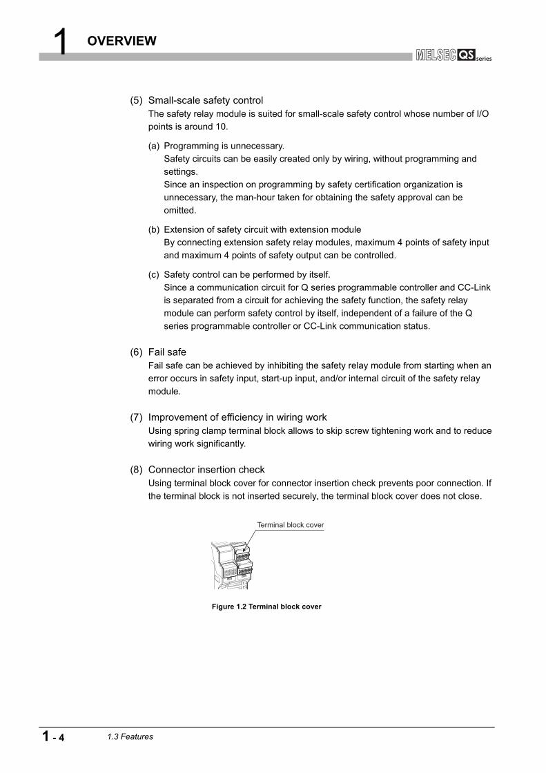
(8) Connector insertion checkUsing terminal block cover for connector insertion check prevents poor connection. If
the terminal block is not inserted securely, the terminal block cover does not close.
Figure 1.2 Terminal block cover
Terminal block cover
1 - 4 1.3 Features
1 OVERVIEW
1
OV
ER
VIE
W
2
SY
ST
EM
C
ON
FIG
UR
AT
ION
3
SP
EC
IFIC
AT
ION
S
4
FU
NC
TIO
NS
5
SE
TT
ING
S A
ND
P
RO
CE
DU
RE
S B
EF
OR
E
OP
ER
AT
ION
6
TR
OU
BL
ES
HO
OT
ING
AP
PE
ND
IX
1.4 Checking the Safety Relay Module Model
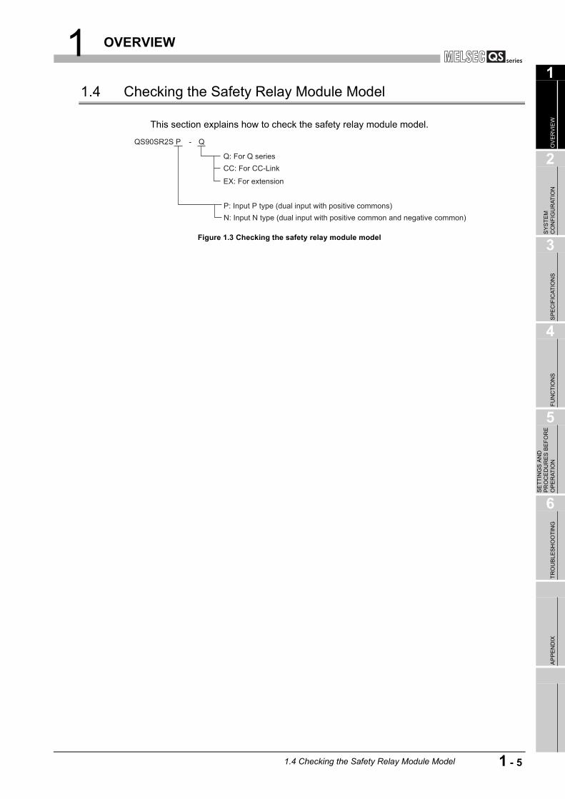
This section explains how to check the safety relay module model.
Figure 1.3 Checking the safety relay module model
N: Input N type (dual input with positive common and negative common)P: Input P type (dual input with positive commons)
EX: For extension
-
CC: For CC-LinkQ: For Q series
QS90SR2S P Q
1.4 Checking the Safety Relay Module Model
1 - 5

2 SYSTEM CONFIGURATION
CHAPTER 2 SYSTEM CONFIGURATION
This chapter explains the system configuration, precautions for use, and system
equipment of the safety relay module.
2.1 System Configuration
Figure 2.1 shows system configuration using the safety relay module.
Figure 2.1 System configuration
Po
we
r su
pp
ly m
od
ule
CP
U m
od
ule
Q s
erie
s s
afe
ty re
lay
mo
du
le
Ma
ste
r sta
tion
Extension
safety
relay module
Extension
safety
relay module
Extension
safety
relay module
Extension
safety
relay module
Extension
safety
relay module
Extension
safety
relay module
Extension
safety
relay module
Remote I/O
station
CC-Link safety
relay module
CC-Link safety
relay module
Safety part
Communication part
Safety part
Communication part
2 - 1 2.1 System Configuration

2 SYSTEM CONFIGURATION
1
OV
ER
VIE
W
2
SY
ST
EM
C
ON
FIG
UR
AT
ION
3
SP
EC
IFIC
AT
ION
S
4
FU
NC
TIO
NS
5
SE
TT
ING
S A
ND
P
RO
CE
DU
RE
S B
EF
OR
E
OP
ER
AT
ION
6
TR
OU
BL
ES
HO
OT
ING
AP
PE
ND
IX
2.2 Applicable Systems
(1) Mountable modules, the number of mountable modules, and mountable base units
(a) Q series safety relay module
1) When mounting to CPU module
The following table shows the mountable CPU modules, the number of
mountable modules, and mountable base units of the Q series safety relay
module.
Shortage of power capacity may occur depending on the combination with
other mounted modules or the number of mounted modules.
When mounting modules, pay attention to the power capacity.
When shortage of power capacity occurs, review the combination of modules
to be mounted.
: Mountable, : Not mountable * 1: Limited within the range of the number of I/O points for the CPU module. * 2: Mountable on any I/O slots of the mountable base unit.
Table 2.1 Applicable modules and the number of mountable modules
Mountable CPU module Number of
mountable
modules*1
Mountable base unit*2
CPU type CPU model Main base unitExtension base
unit
Programmable
controller CPU
Basic model QCPU
Q00JCPU Up to 8
Q00CPUUp to 12
Q01CPU
High Performance
model QCPU
Q02(H)CPU
Up to 32Q06HCPU
Q12HCPU
Q25HCPU
Process CPU
Q02PHCPU
Up to 32Q06PHCPU
Q12PHCPU
Q25PHCPU
Universal model
QCPU
Q00UJCPU Up to 8
Q00UCPUUp to 12
Q01UCPU
Q02UCPU Up to 18
Q03UD(E)CPU
Up to 32
Q04UD(E)HCPU
Q06UD(E)HCPU
Q10UD(E)HCPU
Q13UD(E)HCPU
Q20UD(E)HCPU
Q26UD(E)HCPU
Q50UDEHCPU
Q100UDEHCPU
Redundant CPUQ12PRHCPU
Up to 31Q25PRHCPU
C Controller module
Q06CCPU-V
Up to 32Q06CCPU-V-B
Q12DCCPU-V
2.2 Applicable Systems
2 - 2
2 SYSTEM CONFIGURATION
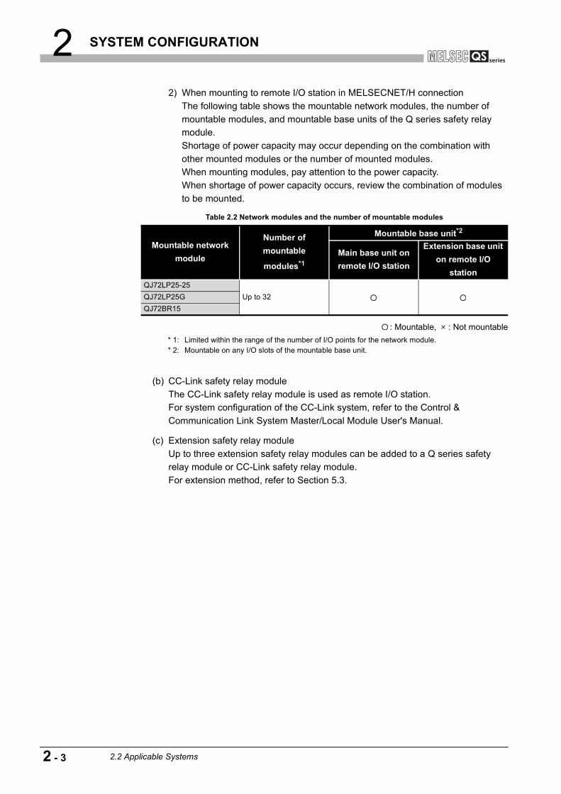
2) When mounting to remote I/O station in MELSECNET/H connection
The following table shows the mountable network modules, the number of
mountable modules, and mountable base units of the Q series safety relay
module.
Shortage of power capacity may occur depending on the combination with
other mounted modules or the number of mounted modules.
When mounting modules, pay attention to the power capacity.
When shortage of power capacity occurs, review the combination of modules
to be mounted.
: Mountable, : Not mountable
* 1: Limited within the range of the number of I/O points for the network module. * 2: Mountable on any I/O slots of the mountable base unit.
(b) CC-Link safety relay module
The CC-Link safety relay module is used as remote I/O station.
For system configuration of the CC-Link system, refer to the Control &
Communication Link System Master/Local Module User's Manual.
(c) Extension safety relay module
Up to three extension safety relay modules can be added to a Q series safety
relay module or CC-Link safety relay module.
For extension method, refer to Section 5.3.
Table 2.2 Network modules and the number of mountable modules
Mountable network
module
Number of
mountable
modules*1
Mountable base unit*2
Main base unit on
remote I/O station
Extension base unit
on remote I/O
station
QJ72LP25-25
Up to 32QJ72LP25G
QJ72BR15
2 - 3 2.2 Applicable Systems

2 SYSTEM CONFIGURATION
1
OV
ER
VIE
W
2
SY
ST
EM
C
ON
FIG
UR
AT
ION
3
SP
EC
IFIC
AT
ION
S
4
FU
NC
TIO
NS
5
SE
TT
ING
S A
ND
P
RO
CE
DU
RE
S B
EF
OR
E
OP
ER
AT
ION
6
TR
OU
BL
ES
HO
OT
ING
AP
PE
ND
IX
2.3 Module Replacement
Replace the product according to the replacement cycle shown in the table below.
2.4 Precautions for Use
Users must prove that their entire safety system complies with the safety standards and
the Machinery Directive. The third-party certification organization will validate the safety of
product for the entire safety system, including a safety relay module and safety
components.
To establish a safety system, calculate the target performance level (PL) for each safety
application (safety function) based on the MTTFd and DCavg values of the safety relay
module and connected safety components. The calculation equation is shown in
ISO13849-1: 2015.
MTTFd and DCavg of the safety relay module are shown in following.
Table 2.3 Module replacement cycle
Module Module replacement cycle
Q series/CC-Link/Extension safety relay module 10 years
Table 2.4 MTTFd and DCavg of the safety relay module
Module MTTFd DCavg
Safety relay module >100 years 99%
2.3 Module Replacement
2 - 4
3 SPECIFICATIONS
CHAPTER 3 SPECIFICATIONS
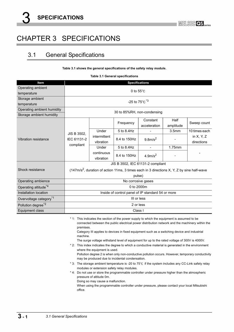
3.1 General Specifications
Table 3.1 shows the general specifications of the safety relay module.
* 1: This indicates the section of the power supply to which the equipment is assumed to be connected between the public electrical power distribution network and the machinery within the premises.Category III applies to devices in fixed equipment such as a switching device and industrial machine.The surge voltage withstand level of equipment for up to the rated voltage of 300V is 4000V.
* 2: This index indicates the degree to which a conductive material is generated in the environment
where the equipment is used.Pollution degree 2 is when only non-conductive pollution occurs. However, temporary conductivity may be produced due to incidental condensation.
* 3: The storage ambient temperature is -20 to 75 if the system includes any CC-Link safety relay
modules or extension safety relay modules. * 4: Do not use or store the programmable controller under pressure higher than the atmospheric
pressure of altitude 0m.Doing so may cause a malfunction.When using the programmable controller under pressure, please contact your local Mitsubishi office.
Table 3.1 General specifications
Item Specifications
Operating ambient
temperature0 to 55
Storage ambient
temperature-25 to 75 *3
Operating ambient humidity30 to 85%RH, non-condensing
Storage ambient humidity
Vibration resistance
JIS B 3502,
IEC 61131-2
compliant
FrequencyConstant
acceleration
Half
amplitudeSweep count
Under
intermittent
vibration
5 to 8.4Hz - 3.5mm 10 times each
in X, Y, Z
directions8.4 to 150Hz 9.8m/s2 -
Under
continuous
vibration
5 to 8.4Hz - 1.75mm
-8.4 to 150Hz 4.9m/s2 -
Shock resistance
JIS B 3502, IEC 61131-2 compliant
(147m/s2, duration of action 11ms, 3 times each in 3 directions X, Y, Z by sine half-wave
pulse)
Operating ambience No corrosive gases
Operating altitude*4 0 to 2000m
Installation location Inside of control panel of IP standard 54 or more
Overvoltage category*1 III or less
Pollution degree*2 2 or less
Equipment class Class I
3 - 1 3.1 General Specifications
3 SPECIFICATIONS
1
OV
ER
VIE
W
2
SY
ST
EM
C
ON
FIG
UR
AT
ION
3
SP
EC
IFIC
AT
ION
S
4
FU
NC
TIO
NS
5
SE
TT
ING
S A
ND
P
RO
CE
DU
RE
S B
EF
OR
E
OP
ER
AT
ION
6
TR
OU
BL
ES
HO
OT
ING
AP
PE
ND
IX
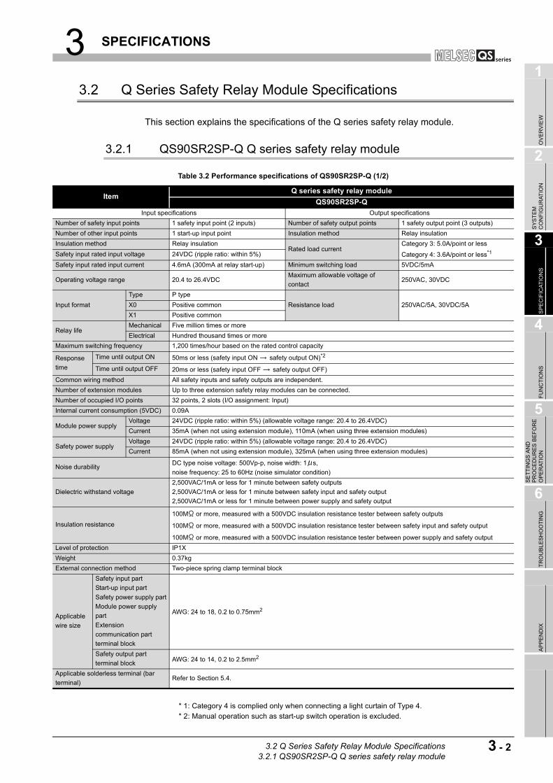
3.2 Q Series Safety Relay Module Specifications
This section explains the specifications of the Q series safety relay module.
3.2.1 QS90SR2SP-Q Q series safety relay module
* 1: Category 4 is complied only when connecting a light curtain of Type 4. * 2: Manual operation such as start-up switch operation is excluded.
Table 3.2 Performance specifications of QS90SR2SP-Q (1/2)
ItemQ series safety relay module
QS90SR2SP-Q
Input specifications Output specifications
Number of safety input points 1 safety input point (2 inputs) Number of safety output points 1 safety output point (3 outputs)
Number of other input points 1 start-up input point Insulation method Relay insulation
Insulation method Relay insulationRated load current
Category 3: 5.0A/point or less
Category 4: 3.6A/point or less*1Safety input rated input voltage 24VDC (ripple ratio: within 5%)
Safety input rated input current 4.6mA (300mA at relay start-up) Minimum switching load 5VDC/5mA
Operating voltage range 20.4 to 26.4VDCMaximum allowable voltage of
contact250VAC, 30VDC
Input format
Type P type
Resistance load 250VAC/5A, 30VDC/5AX0 Positive common
X1 Positive common
Relay lifeMechanical Five million times or more
Electrical Hundred thousand times or more
Maximum switching frequency 1,200 times/hour based on the rated control capacity
Response
time
Time until output ON 50ms or less (safety input ON safety output ON)*2
Time until output OFF 20ms or less (safety input OFF safety output OFF)
Common wiring method All safety inputs and safety outputs are independent.
Number of extension modules Up to three extension safety relay modules can be connected.
Number of occupied I/O points 32 points, 2 slots (I/O assignment: Input)
Internal current consumption (5VDC) 0.09A
Module power supplyVoltage 24VDC (ripple ratio: within 5%) (allowable voltage range: 20.4 to 26.4VDC)
Current 35mA (when not using extension module), 110mA (when using three extension modules)
Safety power supplyVoltage 24VDC (ripple ratio: within 5%) (allowable voltage range: 20.4 to 26.4VDC)
Current 85mA (when not using extension module), 325mA (when using three extension modules)
Noise durabilityDC type noise voltage: 500Vp-p, noise width: 1 s,
noise frequency: 25 to 60Hz (noise simulator condition)
Dielectric withstand voltage
2,500VAC/1mA or less for 1 minute between safety outputs
2,500VAC/1mA or less for 1 minute between safety input and safety output
2,500VAC/1mA or less for 1 minute between power supply and safety output
Insulation resistance
100M or more, measured with a 500VDC insulation resistance tester between safety outputs
100M or more, measured with a 500VDC insulation resistance tester between safety input and safety output
100M or more, measured with a 500VDC insulation resistance tester between power supply and safety output
Level of protection IP1X
Weight 0.37kg
External connection method Two-piece spring clamp terminal block
Applicable
wire size
Safety input part
Start-up input part
Safety power supply part
Module power supply
part
Extension
communication part
terminal block
AWG: 24 to 18, 0.2 to 0.75mm2
Safety output part
terminal blockAWG: 24 to 14, 0.2 to 2.5mm2
Applicable solderless terminal (bar
terminal)Refer to Section 5.4.
3.2 Q Series Safety Relay Module Specifications3.2.1 QS90SR2SP-Q Q series safety relay module
3 - 2
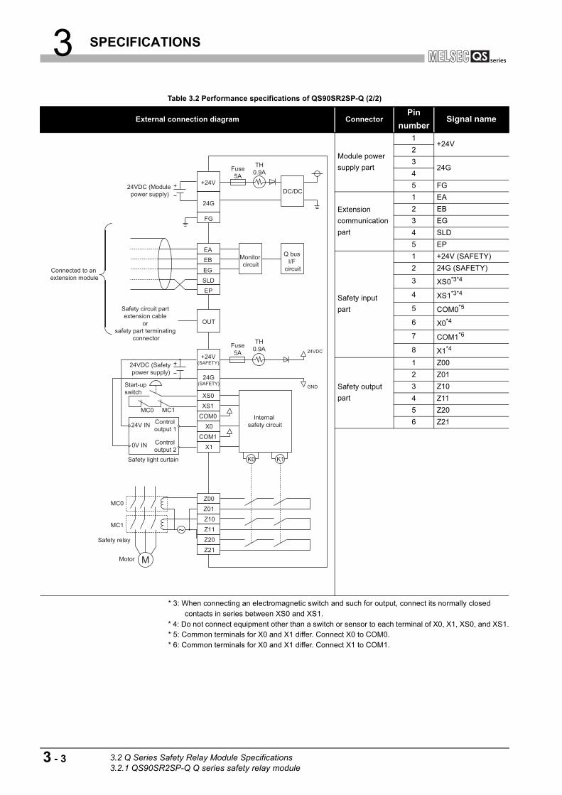
3 SPECIFICATIONS
* 3: When connecting an electromagnetic switch and such for output, connect its normally closed contacts in series between XS0 and XS1.
* 4: Do not connect equipment other than a switch or sensor to each terminal of X0, X1, XS0, and XS1. * 5: Common terminals for X0 and X1 differ. Connect X0 to COM0. * 6: Common terminals for X0 and X1 differ. Connect X1 to COM1.
Table 3.2 Performance specifications of QS90SR2SP-Q (2/2)
External connection diagram ConnectorPin
numberSignal name
Module power
supply part
1+24V
2
324G
4
5 FG
Extension
communication
part
1 EA
2 EB
3 EG
4 SLD
5 EP
Safety input
part
1 +24V (SAFETY)
2 24G (SAFETY)
3 XS0*3*4
4 XS1*3*4
5 COM0*5
6 X0*4
7 COM1*6
8 X1*4
Safety output
part
1 Z00
2 Z01
3 Z10
4 Z11
5 Z20
6 Z21
Safety relayZ21
M
Z20
Z11
Z10
Z01MC0
MC1
Z00
Motor
EP
SLD
EG
EBEA
COM1
X1
X0
24G(SAFETY)
+24V(SAFETY)24VDC (Safety
power supply)
24VDC (Module power supply)
COM024V IN
0V IN Control output 2
Control output 1
XS1
XS0
MC0 MC1
Start-up switch
24G
+24V
FG
K1K0
Internal safety circuit
24VDC
TH0.9AFuse
5A
TH0.9AFuse
5A
Monitor circuit
Q bus I/F
circuit
GND
DC/DC
Safety light curtain
OUT
Safety circuit part extension cable
or safety part terminating
connector
Connected to an extension module
3 - 3 3.2 Q Series Safety Relay Module Specifications3.2.1 QS90SR2SP-Q Q series safety relay module

3 SPECIFICATIONS
1
OV
ER
VIE
W
2
SY
ST
EM
C
ON
FIG
UR
AT
ION
3
SP
EC
IFIC
AT
ION
S
4
FU
NC
TIO
NS
5
SE
TT
ING
S A
ND
P
RO
CE
DU
RE
S B
EF
OR
E
OP
ER
AT
ION
6
TR
OU
BL
ES
HO
OT
ING
AP
PE
ND
IX
3.2.2 QS90SR2SN-Q Q series safety relay module
* 1: Manual operation such as start-up switch operation is excluded.
Table 3.3 Performance specifications of QS90SR2SN-Q (1/2)
ItemQ series safety relay module
QS90SR2SN-Q
Input specifications Output specifications
Number of safety input points 1 safety input point (2 inputs) Number of safety output points 1 safety output point (3 outputs)
Number of other input points 1 start-up input point Insulation method Relay insulation
Insulation method Relay insulationRated load current
Category 4: 3.6A/point or less
(Category 3: 5.0A/point or less)Safety input rated input voltage 24VDC (ripple ratio: within 5%)
Safety input rated input current 4.6mA (300mA at relay start-up) Minimum switching load 5VDC/5mA
Operating voltage range 20.4 to 26.4VDCMaximum allowable voltage of
contact250VAC, 30VDC
Input format
Type N type
Resistance load 250VAC/5A, 30VDC/5AX0 Positive common
X1 Negative common
Relay lifeMechanical Five million times or more
Electrical Hundred thousand times or more
Maximum switching frequency 1,200 times/hour based on the rated control capacity
Response
time
Time until output ON 50ms or less (safety input ON safety output ON)*1
Time until output OFF 20ms or less (safety input OFF safety output OFF)
Common wiring method All safety inputs and safety outputs are independent.
Number of extension modules Up to three extension safety relay modules can be connected.
Number of occupied I/O points 32 points, 2 slots (I/O assignment: Input)
Internal current consumption (5VDC) 0.09A
Module power supplyVoltage 24VDC (ripple ratio: within 5%) (allowable voltage range: 20.4 to 26.4VDC)
Current 35mA (when not using extension module), 110mA (when using three extension modules)
Safety power supplyVoltage 24VDC (ripple ratio: within 5%) (allowable voltage range: 20.4 to 26.4VDC)
Current 85mA (when not using extension module), 325mA (when using three extension modules)
Noise durabilityDC type noise voltage: 500Vp-p, noise width: 1 s,
noise frequency: 25 to 60Hz (noise simulator condition)
Dielectric withstand voltage
2,500VAC/1mA or less for 1 minute between safety outputs
2,500VAC/1mA or less for 1 minute between safety input and safety output
2,500VAC/1mA or less for 1 minute between power supply and safety output
Insulation resistance
100M or more, measured with a 500VDC insulation resistance tester between safety outputs
100M or more, measured with a 500VDC insulation resistance tester between safety input and safety output
100M or more, measured with a 500VDC insulation resistance tester between power supply and safety output
Level of protection IP1X
Weight 0.37kg
External connection method Two-piece spring clamp terminal block
Applicable
wire size
Safety input part
Start-up input part
Safety power supply part
Module power supply
part
Extension
communication part
terminal block
AWG: 24 to 18, 0.2 to 0.75mm2
Safety output part
terminal blockAWG: 24 to 14, 0.2 to 2.5mm2
Applicable solderless terminal (bar
terminal)Refer to Section 5.4.
3.2 Q Series Safety Relay Module Specifications3.2.2 QS90SR2SN-Q Q series safety relay module
3 - 4

3 SPECIFICATIONS
* 2: When connecting an electromagnetic switch and such for output, connect its normally closed contacts in series between XS0 and XS1.
* 3: Do not connect equipment other than a switch or sensor to each terminal of X0, X1, XS0, and XS1. * 4: Common terminals for X0 and X1 differ. Connect X0 to COM0. * 5: Common terminals for X0 and X1 differ. Connect X1 to COM1.
Table 3.3 Performance specifications of QS90SR2SN-Q (2/2)
External connection diagram ConnectorPin
numberSignal name
Module power
supply part
1+24V
2
324G
4
5 FG
Extension
communication
part
1 EA
2 EB
3 EG
4 SLD
5 EP
Safety input
part
1 +24V (SAFETY)
2 24G (SAFETY)
3 XS0*2*3
4 XS1*2*3
5 COM0*4
6 X0*3
7 COM1*5
8 X1*3
Safety output
part
1 Z00
2 Z01
3 Z10
4 Z11
5 Z20
6 Z21
Safety relayZ21
M
Z20
Z11
Z10
Z01MC0
MC1
Z00
Motor
EP
SLD
EG
EBEA
COM1
X1
X0
24G(SAFETY)
+24V(SAFETY)
24VDC (Module power supply)
COM0
XS1
XS0
MC0 MC1
Start-up switch
24G
+24V
FG
K1K0
Internal safety circuit
24VDC
TH0.9AFuse
5A
TH0.9AFuse
5A
Monitor circuit
Q bus I/F
circuit
GND
DC/DC
Safety doorOpen
24VDC (Safety power supply)
Safety limit switch
OUT
Safety circuit part extension cable
or safety part terminating
connector
Connected to an extension module
3 - 5 3.2 Q Series Safety Relay Module Specifications3.2.2 QS90SR2SN-Q Q series safety relay module

3 SPECIFICATIONS
1
OV
ER
VIE
W
2
SY
ST
EM
C
ON
FIG
UR
AT
ION
3
SP
EC
IFIC
AT
ION
S
4
FU
NC
TIO
NS
5
SE
TT
ING
S A
ND
P
RO
CE
DU
RE
S B
EF
OR
E
OP
ER
AT
ION
6
TR
OU
BL
ES
HO
OT
ING
AP
PE
ND
IX
3.3 CC-Link Safety Relay Module Specifications
This section explains the specifications of the CC-Link safety relay module.
3.3.1 QS90SR2SP-CC CC-Link safety relay module
* 1: Category 4 is complied only when connecting a light curtain of Type 4. * 2: Manual operation such as start-up switch operation is excluded.
Table 3.4 Performance specifications of QS90SR2SP-CC (1/2)
ItemCC-Link safety relay module
QS90SR2SP-CC
Input specifications Output specifications
Number of safety input points 1 safety input point (2 inputs) Number of safety output points 1 safety output point (3 outputs)
Number of other input points 1 start-up input point Insulation method Relay insulation
Insulation method Relay insulationRated load current
Category 3: 5.0A/point or less
Category 4: 3.6A/point or less*1Safety input rated input voltage 24VDC (ripple ratio: within 5%)
Safety input rated input current4.6mA (300mA at relay start-
up)Minimum switching load 5VDC/5mA
Operating voltage range 20.4 to 26.4VDC Maximum allowable voltage of contact 250VAC, 30VDC
Input format
Type P type
Resistance load 250VAC/5A, 30VDC/5AX0 Positive common
X1 Positive common
Relay lifeMechanical Five million times or more
Electrical Hundred thousand times or more
Maximum switching frequency 1,200 times/hour based on the rated control capacity
Response
time
Time until output ON 50ms or less (safety input ON safety output ON)*2
Time until output OFF 20ms or less (safety input OFF safety output OFF)
Common wiring method All safety inputs and safety outputs are independent.
Number of extension modules Up to three extension safety relay modules can be connected.
Number of occupied stations 32-point assigned per station (32 points used)
Module power supplyVoltage 24VDC (ripple ratio: within 5%) (allowable voltage range: 20.4 to 26.4VDC)
Current 70mA (when not using extension module), 145mA (when using three extension modules)
Safety power supplyVoltage 24VDC (ripple ratio: within 5%) (allowable voltage range: 20.4 to 26.4VDC)
Current 85mA (when not using extension module), 325mA (when using three extension modules)
Noise durabilityDC type noise voltage: 500Vp-p, noise width: 1 s,
noise frequency: 25 to 60Hz (noise simulator condition)
Dielectric withstand voltage
2,500VAC/1mA or less for 1 minute between safety outputs
2,500VAC/1mA or less for 1 minute between safety input and safety output
2,500VAC/1mA or less for 1 minute between power supply and safety output
Insulation resistance
100M or more, measured with a 500VDC insulation resistance tester between safety outputs
100M or more, measured with a 500VDC insulation resistance tester between safety input and safety
output
100M or more, measured with a 500VDC insulation resistance tester between power supply and safety
output
Level of protection IP1X
Weight 0.37kg
External connection method Two-piece spring clamp terminal block
Applicable
wire size
Safety input part
Start-up input part
Safety power supply part
Module power supply part
Safety output part terminal block
AWG: 24 to 14, 0.2 to 2.5mm2
CC-Link part
Extension communication part
terminal blockAWG: 24 to 16, 0.2 to 1.25mm2
Applicable solderless terminal (bar terminal) Refer to Section 5.4.
Applicable DIN rail TH35-7.5Fe, TH35-7.5Al (JIS C 2812 compliant)
3.3 CC-Link Safety Relay Module Specifications3.3.1 QS90SR2SP-CC CC-Link safety relay module
3 - 6

3 SPECIFICATIONS
* 3: When connecting an electromagnetic switch and such for output, connect its normally closed contacts in series between XS0 and XS1.
* 4: Do not connect equipment other than a switch or sensor to each terminal of X0, X1, XS0, and XS1. * 5: Common terminals for X0 and X1 differ. Pay attention to the printing on the module at wiring. In the
external connection diagram, they are represented as COM (X0) and COM (X1).
Table 3.4 Performance specifications of QS90SR2SP-CC (2/2)
External connection diagram ConnectorPin
numberSignal name
Module power
supply part
1+24V
2
324G
4
CC-Link part
1 DA
2 DB
3 DG
4 SLD
Extension
communication
part
1 EA
2 EB
3 EG
4 EP
Safety power
supply, start-up
input part
1 XS0*3*4
2 XS1*3*4
3 +24V (SAFETY)
4 24G (SAFETY)
Safety input
part
1 COM(X0)*5
2 X0*4
3 COM(X1)*5
4 X1*4
Safety output
part 1
1 Empty
2 Z00
3 Z10
4 Z20
Safety output
part 2
1 Empty
2 Z01
3 Z11
4 Z21
Safety relay
Z21
M
Z20
Z11
Z10
Z01MC0
MC1
Z00
Motor
EP
EG
EBEA
COM(X1)
X1
X0
24G(SAFETY)
+24V(SAFETY)24VDC (Safety
power supply)
24VDC (Module power supply)
COM(X0)24V IN
0V IN Control output 2
Control output 1
XS1
XS0
MC0 MC1
Start-up switch
24G
+24V
K1K0
Internal safety circuit
24VDC
TH0.9AFuse
5A
TH0.9AFuse
5A
Monitorcircuit
GND
DC/DC
SLD
DG
DBDA
CC-Linkcircuit
Safety light curtain
OUTSafety circuit part extension cable
or safety part terminating
connector
Connected to an extension module
COM(X0) COM(X1)
3 - 7 3.3 CC-Link Safety Relay Module Specifications3.3.1 QS90SR2SP-CC CC-Link safety relay module

3 SPECIFICATIONS
1
OV
ER
VIE
W
2
SY
ST
EM
C
ON
FIG
UR
AT
ION
3
SP
EC
IFIC
AT
ION
S
4
FU
NC
TIO
NS
5
SE
TT
ING
S A
ND
P
RO
CE
DU
RE
S B
EF
OR
E
OP
ER
AT
ION
6
TR
OU
BL
ES
HO
OT
ING
AP
PE
ND
IX
3.3.2 QS90SR2SN-CC CC-Link safety relay module
* 1: Manual operation such as start-up switch operation is excluded.
Table 3.5 Performance specifications of QS90SR2SN-CC (1/2)
ItemCC-Link safety relay module
QS90SR2SN-CC
Input specifications Output specifications
Number of safety input points 1 safety input point (2 inputs) Number of safety output points 1 safety output point (3 outputs)
Number of other input points 1 start-up input point Insulation method Relay insulation
Insulation method Relay insulationRated load current
Category 4: 3.6A/point or less
(Category 3: 5.0A/point or less)Safety input rated input voltage 24VDC (ripple ratio: within 5%)
Safety input rated input current 4.6mA (300mA at relay start-up) Minimum switching load 5VDC/5mA
Operating voltage range 20.4 to 26.4VDCMaximum allowable voltage of
contact250VAC, 30VDC
Input format
Type N type
Resistance load 250VAC/5A, 30VDC/5AX0 Positive common
X1 Negative common
Relay lifeMechanical Five million times or more
Electrical Hundred thousand times or more
Maximum switching frequency 1,200 times/hour based on the rated control capacity
Response timeTime until output ON 50ms or less (safety input ON safety output ON)*1
Time until output OFF 20ms or less (safety input OFF safety output OFF)
Common wiring method All safety inputs and safety outputs are independent.
Number of extension modules Up to three extension safety relay modules can be connected.
Number of occupied stations 32-point assigned per station (32 points used)
Module power supplyVoltage 24VDC (ripple ratio: within 5%) (allowable voltage range: 20.4 to 26.4VDC)
Current 70mA (when not using extension module), 145mA (when using three extension modules)
Safety power supplyVoltage 24VDC (ripple ratio: within 5%) (allowable voltage range: 20.4 to 26.4VDC)
Current 85mA (when not using extension module), 325mA (when using three extension modules)
Noise durabilityDC type noise voltage: 500Vp-p, noise width: 1 s,
noise frequency: 25 to 60Hz (noise simulator condition)
Dielectric withstand voltage
2,500VAC/1mA or less for 1 minute between safety outputs
2,500VAC/1mA or less for 1 minute between safety input and safety output
2,500VAC/1mA or less for 1 minute between power supply and safety output
Insulation resistance
100M or more, measured with a 500VDC insulation resistance tester between safety outputs
100M or more, measured with a 500VDC insulation resistance tester between safety input and safety
output
100M or more, measured with a 500VDC insulation resistance tester between power supply and safety
output
Level of protection IP1X
Weight 0.37kg
External connection method Two-piece spring clamp terminal block
Applicable wire
size
Safety input part
Start-up input part
Safety power supply part
Module power supply part
Safety output part terminal
block
AWG: 24 to 14, 0.2 to 2.5mm2
CC-Link part
Extension communication part
terminal blockAWG: 24 to 16, 0.2 to 1.25mm2
Applicable solderless terminal (bar terminal) Refer to Section 5.4.
Applicable DIN rail TH35-7.5Fe, TH35-7.5Al (JIS C 2812 compliant)
3.3 CC-Link Safety Relay Module Specifications3.3.2 QS90SR2SN-CC CC-Link safety relay module
3 - 8
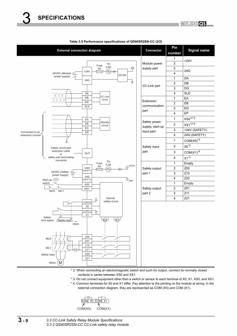
3 SPECIFICATIONS
* 2: When connecting an electromagnetic switch and such for output, connect its normally closed contacts in series between XS0 and XS1.
* 3: Do not connect equipment other than a switch or sensor to each terminal of X0, X1, XS0, and XS1. * 4: Common terminals for X0 and X1 differ. Pay attention to the printing on the module at wiring. In the
external connection diagram, they are represented as COM (X0) and COM (X1).
Table 3.5 Performance specifications of QS90SR2SN-CC (2/2)
External connection diagram ConnectorPin
numberSignal name
Module power
supply part
1+24V
2
324G
4
CC-Link part
1 DA
2 DB
3 DG
4 SLD
Extension
communication
part
1 EA
2 EB
3 EG
4 EP
Safety power
supply, start-up
input part
1 XS0*2*3
2 XS1*2*3
3 +24V (SAFETY)
4 24G (SAFETY)
Safety input
part
1 COM(X0)*4
2 X0*3
3 COM(X1)*4
4 X1*3
Safety output
part 1
1 Empty
2 Z00
3 Z10
4 Z20
Safety output
part 2
1 Empty
2 Z01
3 Z11
4 Z21
Safety relayZ21
M
Z20
Z11
Z10
Z01MC0
MC1
Z00
Motor
COM(X1)
X1
X0
24G(SAFETY)
+24V(SAFETY)
COM(X0)
XS1
XS0
MC0 MC1
Start-up switch
K1K0
Internal safety circuit
24VDC
TH0.9AFuse
5A
GND
Safety doorOpen
24VDC (Safety power supply)
Safety limit switch
EP
EG
EBEA
24VDC (Module power supply)
24G
+24V
TH0.9AFuse
5A
Monitorcircuit
DC/DC
SLD
DG
DBDA
CC-Linkcircuit
OUT
Safety circuit part extension cable
or safety part terminating
connector
Connected to an extension module
COM(X0) COM(X1)
3 - 9 3.3 CC-Link Safety Relay Module Specifications3.3.2 QS90SR2SN-CC CC-Link safety relay module
3 SPECIFICATIONS
1
OV
ER
VIE
W
2
SY
ST
EM
C
ON
FIG
UR
AT
ION
3
SP
EC
IFIC
AT
ION
S
4
FU
NC
TIO
NS
5
SE
TT
ING
S A
ND
P
RO
CE
DU
RE
S B
EF
OR
E
OP
ER
AT
ION
6
TR
OU
BL
ES
HO
OT
ING
AP
PE
ND
IX
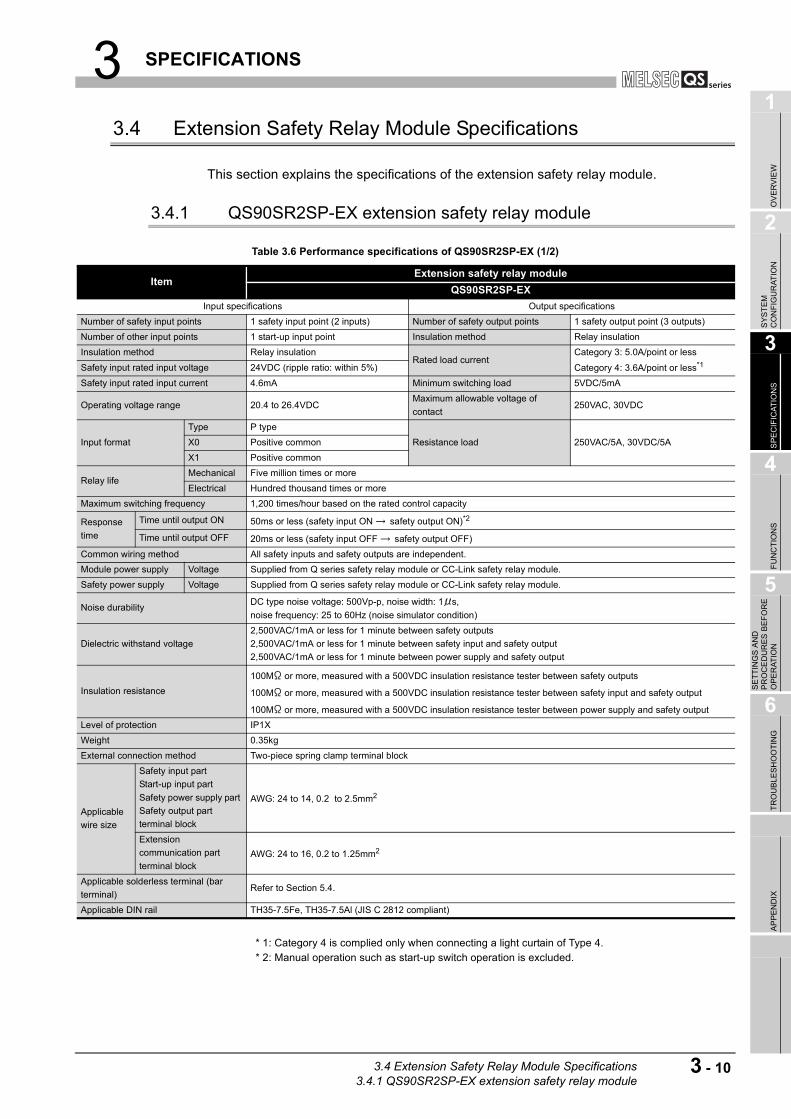
3.4 Extension Safety Relay Module Specifications
This section explains the specifications of the extension safety relay module.
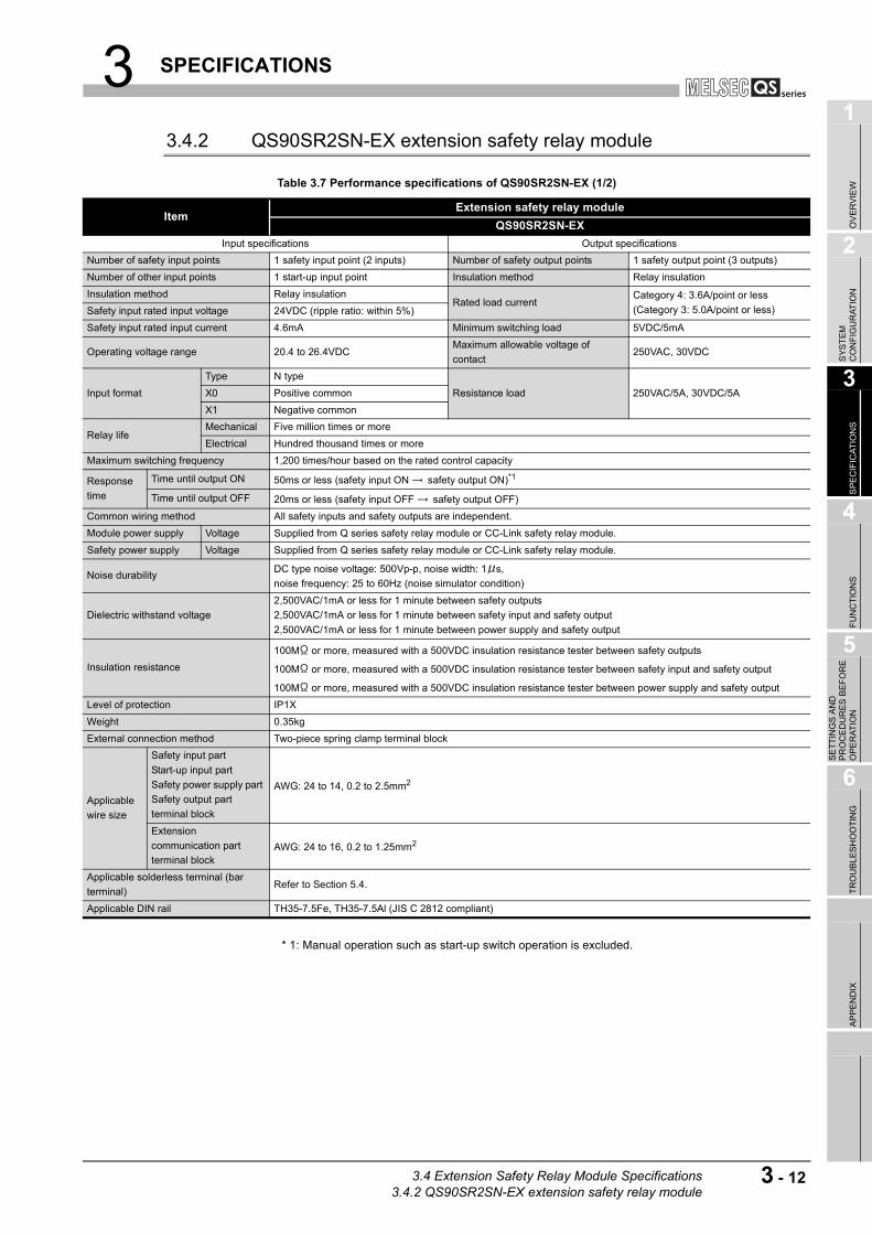
3.4.1 QS90SR2SP-EX extension safety relay module
* 1: Category 4 is complied only when connecting a light curtain of Type 4. * 2: Manual operation such as start-up switch operation is excluded.
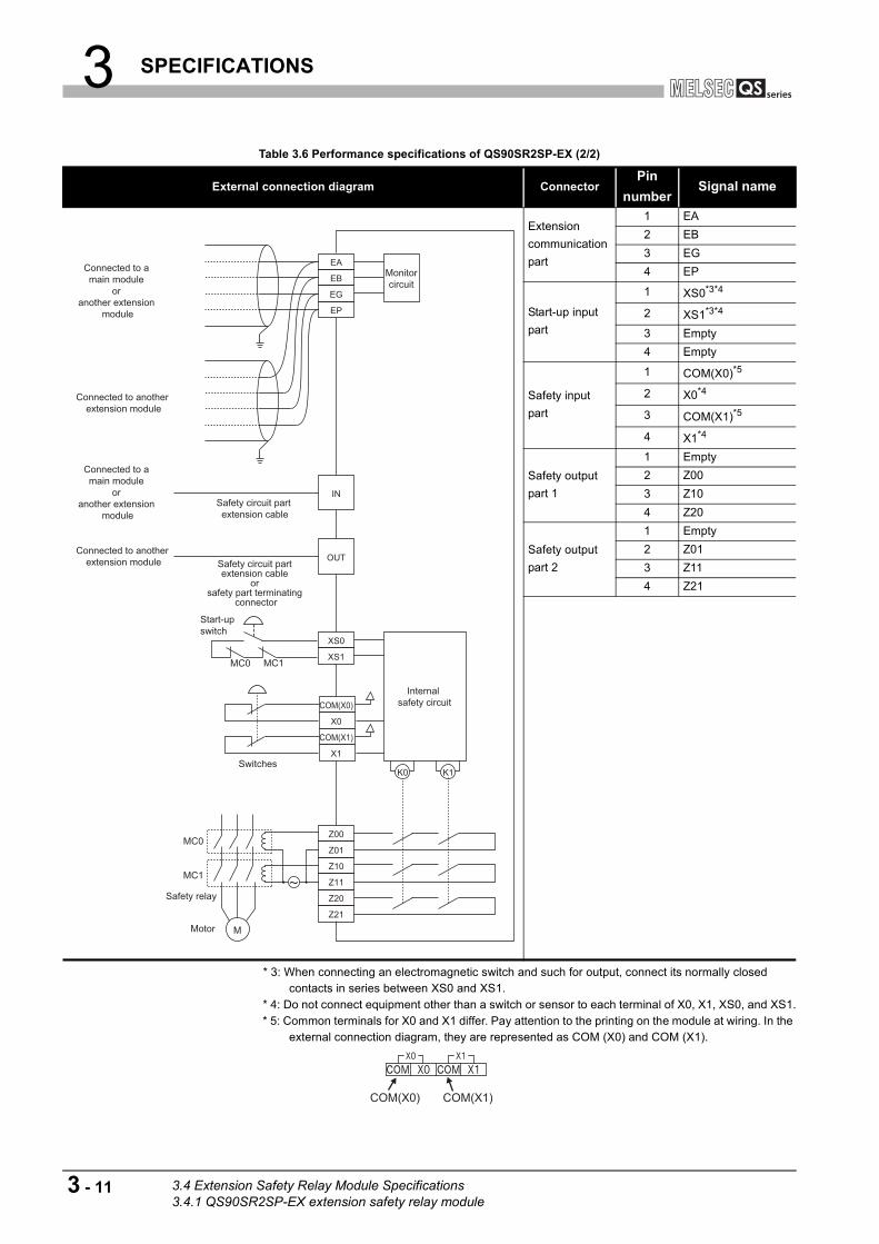
Table 3.6 Performance specifications of QS90SR2SP-EX (1/2)
ItemExtension safety relay module
QS90SR2SP-EX
Input specifications Output specifications
Number of safety input points 1 safety input point (2 inputs) Number of safety output points 1 safety output point (3 outputs)
Number of other input points 1 start-up input point Insulation method Relay insulation
Insulation method Relay insulationRated load current
Category 3: 5.0A/point or less
Category 4: 3.6A/point or less*1Safety input rated input voltage 24VDC (ripple ratio: within 5%)
Safety input rated input current 4.6mA Minimum switching load 5VDC/5mA
Operating voltage range 20.4 to 26.4VDCMaximum allowable voltage of
contact250VAC, 30VDC
Input format
Type P type
Resistance load 250VAC/5A, 30VDC/5AX0 Positive common
X1 Positive common
Relay lifeMechanical Five million times or more
Electrical Hundred thousand times or more
Maximum switching frequency 1,200 times/hour based on the rated control capacity
Response
time
Time until output ON 50ms or less (safety input ON safety output ON)*2
Time until output OFF 20ms or less (safety input OFF safety output OFF)
Common wiring method All safety inputs and safety outputs are independent.
Module power supply Voltage Supplied from Q series safety relay module or CC-Link safety relay module.
Safety power supply Voltage Supplied from Q series safety relay module or CC-Link safety relay module.
Noise durabilityDC type noise voltage: 500Vp-p, noise width: 1 s,
noise frequency: 25 to 60Hz (noise simulator condition)
Dielectric withstand voltage
2,500VAC/1mA or less for 1 minute between safety outputs
2,500VAC/1mA or less for 1 minute between safety input and safety output
2,500VAC/1mA or less for 1 minute between power supply and safety output
Insulation resistance
100M or more, measured with a 500VDC insulation resistance tester between safety outputs
100M or more, measured with a 500VDC insulation resistance tester between safety input and safety output
100M or more, measured with a 500VDC insulation resistance tester between power supply and safety output
Level of protection IP1X
Weight 0.35kg
External connection method Two-piece spring clamp terminal block
Applicable
wire size
Safety input part
Start-up input part
Safety power supply part
Safety output part
terminal block
AWG: 24 to 14, 0.2 to 2.5mm2
Extension
communication part
terminal blockAWG: 24 to 16, 0.2 to 1.25mm2
Applicable solderless terminal (bar
terminal)Refer to Section 5.4.
Applicable DIN rail TH35-7.5Fe, TH35-7.5Al (JIS C 2812 compliant)
3.4 Extension Safety Relay Module Specifications3.4.1 QS90SR2SP-EX extension safety relay module
3 - 10
3 SPECIFICATIONS
* 3: When connecting an electromagnetic switch and such for output, connect its normally closed contacts in series between XS0 and XS1.
* 4: Do not connect equipment other than a switch or sensor to each terminal of X0, X1, XS0, and XS1. * 5: Common terminals for X0 and X1 differ. Pay attention to the printing on the module at wiring. In the
external connection diagram, they are represented as COM (X0) and COM (X1).
Table 3.6 Performance specifications of QS90SR2SP-EX (2/2)
External connection diagram ConnectorPin
numberSignal name
Extension
communication
part
1 EA
2 EB
3 EG
4 EP
Start-up input
part
1 XS0*3*4
2 XS1*3*4
3 Empty
4 Empty
Safety input
part
1 COM(X0)*5
2 X0*4
3 COM(X1)*5
4 X1*4
Safety output
part 1
1 Empty
2 Z00
3 Z10
4 Z20
Safety output
part 2
1 Empty
2 Z01
3 Z11
4 Z21
COM(X0)
X0
X1
COM(X1)
Switches
Connected to a main module
or another extension
module
Connected to another extension module
Connected to a main module
or another extension
module
Connected to another extension module
Safety circuit part extension cable
Safety circuit part extension cable
or safety part terminating
connector
IN
OUT
Monitorcircuit
Internal safety circuit
K0 K1
Start-up switch
MC1MC0
XS0
XS1
EA
EB
EG
EP
Motor
Z00
MC1
MC0Z01
Z10
Z11
Z20
M
Z21
Safety relay
COM(X0) COM(X1)
3 - 11 3.4 Extension Safety Relay Module Specifications3.4.1 QS90SR2SP-EX extension safety relay module
3 SPECIFICATIONS
1
OV
ER
VIE
W
2
SY
ST
EM
C
ON
FIG
UR
AT
ION
3
SP
EC
IFIC
AT
ION
S
4
FU
NC
TIO
NS
5
SE
TT
ING
S A
ND
P
RO
CE
DU
RE
S B
EF
OR
E
OP
ER
AT
ION
6
TR
OU
BL
ES
HO
OT
ING
AP
PE
ND
IX
3.4.2 QS90SR2SN-EX extension safety relay module
* 1: Manual operation such as start-up switch operation is excluded.
Table 3.7 Performance specifications of QS90SR2SN-EX (1/2)
ItemExtension safety relay module
QS90SR2SN-EX
Input specifications Output specifications
Number of safety input points 1 safety input point (2 inputs) Number of safety output points 1 safety output point (3 outputs)
Number of other input points 1 start-up input point Insulation method Relay insulation
Insulation method Relay insulationRated load current
Category 4: 3.6A/point or less
(Category 3: 5.0A/point or less)Safety input rated input voltage 24VDC (ripple ratio: within 5%)
Safety input rated input current 4.6mA Minimum switching load 5VDC/5mA
Operating voltage range 20.4 to 26.4VDCMaximum allowable voltage of
contact250VAC, 30VDC
Input format
Type N type
Resistance load 250VAC/5A, 30VDC/5AX0 Positive common
X1 Negative common
Relay lifeMechanical Five million times or more
Electrical Hundred thousand times or more
Maximum switching frequency 1,200 times/hour based on the rated control capacity
Response
time
Time until output ON 50ms or less (safety input ON safety output ON)*1
Time until output OFF 20ms or less (safety input OFF safety output OFF)
Common wiring method All safety inputs and safety outputs are independent.
Module power supply Voltage Supplied from Q series safety relay module or CC-Link safety relay module.
Safety power supply Voltage Supplied from Q series safety relay module or CC-Link safety relay module.
Noise durabilityDC type noise voltage: 500Vp-p, noise width: 1 s,
noise frequency: 25 to 60Hz (noise simulator condition)
Dielectric withstand voltage
2,500VAC/1mA or less for 1 minute between safety outputs
2,500VAC/1mA or less for 1 minute between safety input and safety output
2,500VAC/1mA or less for 1 minute between power supply and safety output
Insulation resistance
100M or more, measured with a 500VDC insulation resistance tester between safety outputs
100M or more, measured with a 500VDC insulation resistance tester between safety input and safety output
100M or more, measured with a 500VDC insulation resistance tester between power supply and safety output
Level of protection IP1X
Weight 0.35kg
External connection method Two-piece spring clamp terminal block
Applicable
wire size
Safety input part
Start-up input part
Safety power supply part
Safety output part
terminal block
AWG: 24 to 14, 0.2 to 2.5mm2
Extension
communication part
terminal blockAWG: 24 to 16, 0.2 to 1.25mm2
Applicable solderless terminal (bar
terminal)Refer to Section 5.4.
Applicable DIN rail TH35-7.5Fe, TH35-7.5Al (JIS C 2812 compliant)
3.4 Extension Safety Relay Module Specifications3.4.2 QS90SR2SN-EX extension safety relay module
3 - 12

3 SPECIFICATIONS
* 2: When connecting an electromagnetic switch and such for output, connect its normally closed contacts in series between XS0 and XS1.
* 3: Do not connect equipment other than a switch or sensor to each terminal of X0, X1, XS0, and XS1. * 4: Common terminals for X0 and X1 differ. Pay attention to the printing on the module at wiring. In the
external connection diagram, they are represented as COM (X0) and COM (X1).
Table 3.7 Performance specifications of QS90SR2SN-EX (2/2)
External connection diagram ConnectorPin
numberSignal name
Extension
communication
part
1 EA
2 EB
3 EG
4 EP
Start-up input
part
1 XS0*2*3
2 XS1*2*3
3 Empty
4 Empty
Safety input
part
1 COM(X0)*4
2 X0*3
3 COM(X1)*4
4 X1*3
Safety output
part 1
1 Empty
2 Z00
3 Z10
4 Z20
Safety output
part 2
1 Empty
2 Z01
3 Z11
4 Z21
Safety relay
Z21
M
Z20
Z11
Z10
Z01MC0
MC1
Z00
Motor
XS1
XS0
MC0 MC1
Start-up switch
K1K0
Internal safety circuit
COM(X1)
X1
X0
COM(X0)
Safety door
Open
Safety limit switch
EP
EG
EB
EAMonitorcircuit
OUT
IN
Safety circuit part extension cable
or safety part terminating
connector
Safety circuit part extension cable
Connected to another extension module
Connected to a main module
or another extension
module
Connected to another extension module
Connected to a main module
or another extension
module
COM(X0) COM(X1)
3 - 13 3.4 Extension Safety Relay Module Specifications3.4.2 QS90SR2SN-EX extension safety relay module

3 SPECIFICATIONS
1
OV
ER
VIE
W
2
SY
ST
EM
C
ON
FIG
UR
AT
ION
3
SP
EC
IFIC
AT
ION
S
4
FU
NC
TIO
NS
5
SE
TT
ING
S A
ND
P
RO
CE
DU
RE
S B
EF
OR
E
OP
ER
AT
ION
6
TR
OU
BL
ES
HO
OT
ING
AP
PE
ND
IX
3.5 I/O Signals
The following table shows the I/O signals of the safety relay module.
* 1: The signal is always OFF regardless of the safety input status when the input of the main module is OFF.
* 2: K0RB and K1RB indicate whether the actual safety relay contacts K0 and K1 are ON, respectively. This allows a detection of welding of safety relay contact.
Table 3.8 List of I/O signals
Device numberSignal name
Description
Module Q series CC-Link ON OFF
Main module
X0 RX0 X0: Safety input 0 Input No input
X1 RX1 X1: Safety input 1 Input No input
X2 RX2 Z: Safety output Output No output
X3 RX3 XS: Start-up input Input No input
X4 RX4 K0: Internal safety relay K0 drive (coil) Relay drive No relay drive
X5 RX5 K1: Internal safety relay K1 drive (coil) Relay drive No relay drive
X6 RX6K0RB: Internal safety relay K0 output
(contact)*2Relay output No relay output
X7 RX7K1RB: Internal safety relay K1 output
(contact)*2Relay output No relay output
Extension module
(station number 1)
X8 RX8 X0: Safety input 0*1 Input No input
X9 RX9 X1: Safety input 1*1 Input No input
XA RXA Z: Safety output Output No output
XB RXB XS: Start-up input Input No input
XC RXC K0: Internal safety relay K0 drive (coil) Relay drive No relay drive
XD RXD K1: Internal safety relay K1 drive (coil) Relay drive No relay drive
XE RXEK0RB: Internal safety relay K0 output
(contact)*2Relay output No relay output
XF RXFK1RB: Internal safety relay K1 output
(contact)*2Relay output No relay output
Extension module
(station number 2)
X10 RX10 X0: Safety input 0*1 Input No input
X11 RX11 X1: Safety input 1*1 Input No input
X12 RX12 Z: Safety output Output No output
X13 RX13 XS: Start-up input Input No input
X14 RX14 K0: Internal safety relay K0 drive (coil) Relay drive No relay drive
X15 RX15 K1: Internal safety relay K1 drive (coil) Relay drive No relay drive
X16 RX16K0RB: Internal safety relay K0 output
(contact)*2Relay output No relay output
X17 RX17K1RB: Internal safety relay K1 output
(contact)*2Relay output No relay output
Extension module
(station number 3)
X18 RX18 X0: Safety input 0*1 Input No input
X19 RX19 X1: Safety input 1*1 Input No input
X1A RX1A Z: Safety output Output No output
X1B RX1B XS: Start-up input Input No input
X1C RX1C K0: Internal safety relay K0 drive (coil) Relay drive No relay drive
X1D RX1D K1: Internal safety relay K1 drive (coil) Relay drive No relay drive
X1E RX1EK0RB: Internal safety relay K0 output
(contact)*2Relay output No relay output
X1F RX1FK1RB: Internal safety relay K1 output
(contact)*2Relay output No relay output
3.5 I/O Signals
3 - 14
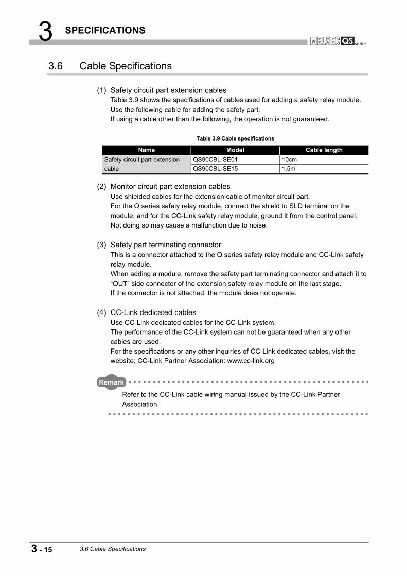
3 SPECIFICATIONS
3.6 Cable Specifications
(1) Safety circuit part extension cablesTable 3.9 shows the specifications of cables used for adding a safety relay module.
Use the following cable for adding the safety part.
If using a cable other than the following, the operation is not guaranteed.
(2) Monitor circuit part extension cablesUse shielded cables for the extension cable of monitor circuit part.
For the Q series safety relay module, connect the shield to SLD terminal on the
module, and for the CC-Link safety relay module, ground it from the control panel.
Not doing so may cause a malfunction due to noise.
(3) Safety part terminating connectorThis is a connector attached to the Q series safety relay module and CC-Link safety
relay module.
When adding a module, remove the safety part terminating connector and attach it to
“OUT” side connector of the extension safety relay module on the last stage.
If the connector is not attached, the module does not operate.
(4) CC-Link dedicated cablesUse CC-Link dedicated cables for the CC-Link system.
The performance of the CC-Link system can not be guaranteed when any other
cables are used.
For the specifications or any other inquiries of CC-Link dedicated cables, visit the
website; CC-Link Partner Association: www.cc-link.org
Remark
Refer to the CC-Link cable wiring manual issued by the CC-Link Partner
Association.
Table 3.9 Cable specifications
Name Model Cable length
Safety circuit part extension
cable
QS90CBL-SE01 10cm
QS90CBL-SE15 1.5m
3 - 15 3.6 Cable Specifications

4 FUNCTIONS
1
OV
ER
VIE
W
2
SY
ST
EM
C
ON
FIG
UR
AT
ION
3
SP
EC
IFIC
AT
ION
S
4
FU
NC
TIO
NS
5
SE
TT
ING
S A
ND
P
RO
CE
DU
RE
S B
EF
OR
E
OP
ER
AT
ION
6
TR
OU
BL
ES
HO
OT
ING
AP
PE
ND
IX
CHAPTER 4 FUNCTIONS
Table 4.1 shows the list of safety relay module functions.
4.1 Dual Input Function
This function doubles safety inputs to prevent damage of the safety functions due to a
single failure.
The doubled safety inputs operate after making sure that the internal module, external
devices, and wiring are normal by the start-up/off check function, Briefly, if a module,
external devices or wiring has a failure, the module does not start.
After module start-up, if one safety input does not turn OFF due to a failure, the output is
cut off by turn-OFF of the other safety input.
Figure 4.1 Dual input wiring
Table 4.1 Function list
Function Description Reference
Dual input function
Prevents damage of the safety functions due to a single failure by doubling
inputs.
•Input N type: Dual input with positive common and negative common
•Input P type: Dual input with positive commons
In case of input N type, when between dual inputs shorts, a short occurs
between the power supply and grounding, resulting in power-OFF with
electric fuse.
Section 4.1
Start-up/off check function Checks that status of the safety relay module and external device are normal. Section 4.2
Start-up method selection functionAllows to select the start-up method either auto mode or manual mode with
the start-up mode setting switch.Section 4.3
Safety output functionPrevents incorrect output due to a single failure by doubling safety relay
contacts internally.Section 4.4
Monitor function
Allows to check operating status of the whole safety relay modules including
extension safety relay modules by connecting with the programmable
controller using programming tool.
Section 4.5
Partial shutdown function with
extension module
Allows to shut off only the outputs of certain modules by using safety inputs of
extension module.Section 4.6
COM0 COM1 X0
Two inputs
One signal
VerificationSafety relay module
X1
4.1 Dual Input Function
4 - 1

4 FUNCTIONS
4.2 Start-up/off Check Function
This function is to start the system after making sure that status of the safety relay module
and external device are normal.
When the safety relay and electromagnetic switch are connected, connecting the normally
closed contacts to the start-up/off check terminal of the safety relay module inhibiting the
start-up at a failure such as contact welding.
Figure 4.2 Off check function
Figure 4.3 Timing chart
POINT
• Connect normally closed contact of forcibly guided type electromagnetic
switch to off check.
• If connecting normally closed contact of electromagnetic switch other
than forcibly guided type, contact separation of the electromagnetic
switch cannot be detected.
• Wire the start-up/off check input so that the external wiring length can be
50m or less.
• The timing of safety input and start-up/off check are inconstant.
Therefore, control using this timing cannot be made.
Safety relay
module
Off check
Start-up
command
Safety status
Safety
outputPower, etc.
Electromagnetic
switch
Non-safety part
Start-up switch
Emergency stop switch
Light curtain,
etc.
The start-up switch turns on.(Manual mode)
Short circuit OpenOpenShort circuit
OFFOFF ONONOFF
Short circuit OpenOpenShort circuit
Activation stateActivation state
Safety output
Start-up input(XS0-XS1)
Off check input
Safety input(X0-COM), (X1-COM)
4 - 2 4.2 Start-up/off Check Function
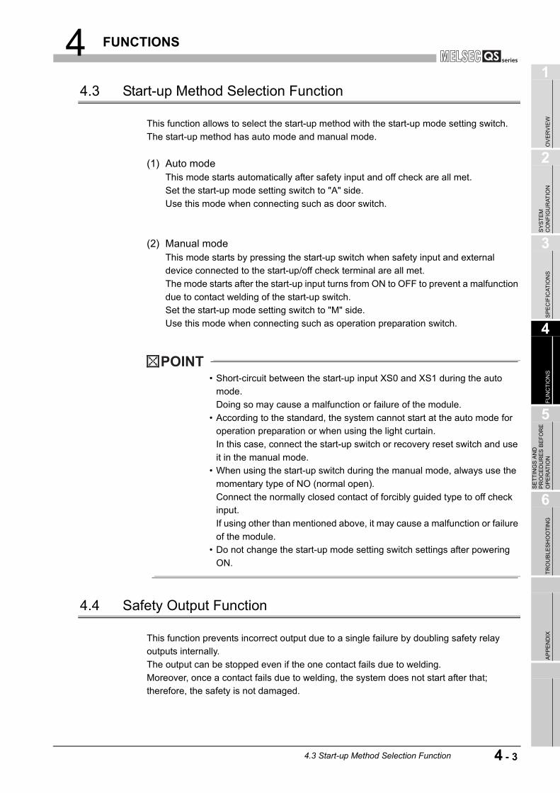
4 FUNCTIONS
1
OV
ER
VIE
W
2
SY
ST
EM
C
ON
FIG
UR
AT
ION
3
SP
EC
IFIC
AT
ION
S
4
FU
NC
TIO
NS
5
SE
TT
ING
S A
ND
P
RO
CE
DU
RE
S B
EF
OR
E
OP
ER
AT
ION
6
TR
OU
BL
ES
HO
OT
ING
AP
PE
ND
IX
4.3 Start-up Method Selection Function
This function allows to select the start-up method with the start-up mode setting switch.
The start-up method has auto mode and manual mode.
(1) Auto modeThis mode starts automatically after safety input and off check are all met.
Set the start-up mode setting switch to "A" side.
Use this mode when connecting such as door switch.
(2) Manual modeThis mode starts by pressing the start-up switch when safety input and external
device connected to the start-up/off check terminal are all met.
The mode starts after the start-up input turns from ON to OFF to prevent a malfunction
due to contact welding of the start-up switch.
Set the start-up mode setting switch to "M" side.
Use this mode when connecting such as operation preparation switch.
POINT
• Short-circuit between the start-up input XS0 and XS1 during the auto
mode.
Doing so may cause a malfunction or failure of the module.
• According to the standard, the system cannot start at the auto mode for
operation preparation or when using the light curtain.
In this case, connect the start-up switch or recovery reset switch and use
it in the manual mode.
• When using the start-up switch during the manual mode, always use the
momentary type of NO (normal open).
Connect the normally closed contact of forcibly guided type to off check
input.
If using other than mentioned above, it may cause a malfunction or failure
of the module.
• Do not change the start-up mode setting switch settings after powering
ON.
4.4 Safety Output Function
This function prevents incorrect output due to a single failure by doubling safety relay
outputs internally.
The output can be stopped even if the one contact fails due to welding.
Moreover, once a contact fails due to welding, the system does not start after that;
therefore, the safety is not damaged.
4.3 Start-up Method Selection Function
4 - 3

4 FUNCTIONS
4.5 Monitor Function
This function allows to check operating status of the whole safety relay modules including
extension safety relay modules by connecting with the programmable controller using
programming tool.
Each module status can be checked as 32-point input from the CPU module.
Figure 4.4 Monitor function
(1) Don’t in the monitor functionConfiguring a safety circuit using the monitor result of safety status with non-safety
device such as programmable controller is inhibited.
Do not use device information gained from the monitor function for controlling safety
devices.
POINT
If the module power supply is powered OFF, monitor signals are not displayed
properly.
Personal computer
(GX Developer)
Safety switch
M1
MC1
MC2Safety relay
module
Programmable
controller
Output
Electromagnetic switch
Device requiring safety control
L1 L2 L3
Non-safety
Monitor of safety information
CC-Link
4 - 4 4.5 Monitor Function

4 FUNCTIONS
1
OV
ER
VIE
W
2
SY
ST
EM
C
ON
FIG
UR
AT
ION
3
SP
EC
IFIC
AT
ION
S
4
FU
NC
TIO
NS
5
SE
TT
ING
S A
ND
P
RO
CE
DU
RE
S B
EF
OR
E
OP
ER
AT
ION
6
TR
OU
BL
ES
HO
OT
ING
AP
PE
ND
IX
4.6 Partial Shutdown Function with Extension Module
This function allows to shut off only the outputs of extension module by using safety inputs
of extension module.
By shutting off only the necessary parts, operating rate of equipment and production line
can be raised.
Figure 4.5 Partial shutdown with extension module
The following shows an operation example when the safety relay module system in Figure
4.5 is configured.
• If SW0, safety input switch of the main module, is pressed, the whole outputs
(M0, M1, M2, M3) are shut off.
• If SW1, safety input switch of the extension module on station number 1, is
pressed, only output of the extension module (M1) is shut off.
• By shorting the safety input of the extension module on station number 3, the
safety input is synchronized with the safety output of the main module and is
driven/shut off.
POINT
The safety output of the extension module can be synchronized only with main
module: therefore; it cannot be synchronized with another extension module.
SW0
SW0
SW1
SW1
SW2
SW2
M3M2
M2
M1
M3
M0
M1M0
Safety
input
Main
module
Extension
module
Station
number 1
Extension
module
Station
number 2
Extension
module
Station
number 3
Short circuit between
COM and input
Operation diagram
Safety
input
Safety
input
Safety
input
Safety
input
Safety
input
Safety
input
4.6 Partial Shutdown Function with Extension Module
4 - 5

5 SETTINGS AND PROCEDURES BEFORE OPERATION
CHAPTER 5 SETTINGS AND PROCEDURES BEFORE OPERATION
This chapter explains settings and procedures before operating the safety relay module.
5.1 Q Series Safety Relay Module
5.1.1 Start-up procedures
Figure 5.1 shows start-up procedures for the Q series safety relay module.
Figure 5.1 Start-up procedures (1/2) * 1: Refer to Section 5.3
Yes
No
Start
Set the extension module station number and extension communication terminating resistor setting switch.*1
Connect the main module and an extension module with a safety circuit part extension cable.*1
Mount a main module on the base unit and install it to a control panel or machine.
Connect an extension module?
Connect the monitor part (EA, EB, EG, EP) with shielded cable.
Connect a safety part terminating connector to the last module.
Set start-up mode with start-up input mode setting switch.
(To next page)
5 - 1 5.1 Q Series Safety Relay Module5.1.1 Start-up procedures

5 SETTINGS AND PROCEDURES BEFORE OPERATION
1
OV
ER
VIE
W
2
SY
ST
EM
C
ON
FIG
UR
AT
ION
3
SP
EC
IFIC
AT
ION
S
4
FU
NC
TIO
NS
5
SE
TT
ING
S A
ND
P
RO
CE
DU
RE
S B
EF
OR
E
OP
ER
AT
ION
6
TR
OU
BL
ES
HO
OT
ING
AP
PE
ND
IX
Figure 5.1 Start-up procedures (2/2)
POINT
When powering ON the system, make sure to power ON the safety power supply
first, and then the module power supply.
If the module power supply is powered ON first, monitor signals cannot be read
properly.
For details, refer to Section 6.1.
Connect the start-up switch between XS0 and XS1.
Connect normally closed contact of the electromagnetic switch to off check.
Yes
No
Start-up mode
(From previous page)
Start-up mode
Connect electromagnetic switch to output?
Auto mode
Auto mode
Manual mode
Manual mode
Check the wiring and settings.
Power-ON
Turn ON the start-up switch.
Check the operating status with LED and others.
End
5.1 Q Series Safety Relay Module5.1.1 Start-up procedures
5 - 2

5 SETTINGS AND PROCEDURES BEFORE OPERATION
5.1.2 Handling precautions
This section explains handling precautions for the Q series safety relay module.
(1) Module fixing screwTighten the module fixing screws and terminal block mounting screws within the
following torque range.
WARNING ● Do not touch the terminals while power is on.
Doing so could result in electric shock.
● Turn off all phases of the external supply power used in the
system when cleaning the module or retightening the
terminal block mounting screws or module mounting screws.
Not doing so could result in electric shock.
Tighten a terminal block mounting screw and module
mounting screw within the specified torque range.
If the terminal block mounting screw is too loose, it may
cause a short-circuit, fire or malfunctions.
If too tight, it may damage the screw and/or the module,
resulting in a drop of the screw or module, a short circuit, or
malfunctions.
If the module mounting screw is too loose, it may cause a
drop of the screw or module.
Over tightening the screw may cause a drop due to the
damage of the screw or module.
CAUTION ● Be sure there are no foreign substances such as sawdust or
wiring debris inside the module.
Such debris could cause a fire, failure, or malfunctions.
● Do not disassemble or remodel the module.
Doing so could cause a failure, malfunctions, injury, or fire.
If the product is repaired or remodeled by other than the
specified FA centers or us, the warranty is not covered.
● Do not directly touch the module's conductive parts or
electronic components.
Doing so may cause malfunctions or a failure.
● When disposing of this product, treat it as industrial waste.
Screw Specified torque range
Module fixing screw (M3) 0.36 to 0.48N m
Terminal block mounting screw (M2.6) 0.20 to 0.30N m
5 - 3 5.1 Q Series Safety Relay Module5.1.2 Handling precautions

5 SETTINGS AND PROCEDURES BEFORE OPERATION
1
OV
ER
VIE
W
2
SY
ST
EM
C
ON
FIG
UR
AT
ION
3
SP
EC
IFIC
AT
ION
S
4
FU
NC
TIO
NS
5
SE
TT
ING
S A
ND
P
RO
CE
DU
RE
S B
EF
OR
E
OP
ER
AT
ION
6
TR
OU
BL
ES
HO
OT
ING
AP
PE
ND
IX
5.1.3 Part names and settings
This section explains each part name of the Q series safety relay module.
Figure 5.2 Q series safety relay module
Table 5.1 Part names (1/2)
Number Name Description
1) Indicator LED
PW
Indicates status of module power supply.
ON: Module power supply is supplied.
OFF: Module power supply is cut off or electric fuse functions.
ERR.
Indicates an error of the station.
Flash: A self-diagnostics error has occurred or safety power supply is cut off.
OFF: Normal
Z
Indicates status of safety output.
ON: Safety output is generated (both K0 and K1 are ON).
OFF: Safety output is not generated.
X0 Indicates status of safety input (X0, X1).
ON: Safety input is generated.
OFF: Safety input is not generated.X1
S PW
Indicates status of safety power supply.
ON: Safety power supply is supplied.
OFF: Safety power supply is cut off or electric fuse functions.
K0
Indicates operating status of the internal safety relay K0 (coil status of K0).
ON: Operating status of the internal safety relay K0 is ON.
OFF: Operating status of the internal safety relay K0 is OFF.
K1
Indicates operating status of the internal safety relay K1 (coil status of K1).
ON: Operating status of the internal safety relay K1 is ON.
OFF: Operating status of the internal safety relay K1 is OFF.
8)
1)
6)
7)
2)
8)
4)
5)
3)
9)
5.1 Q Series Safety Relay Module5.1.3 Part names and settings
5 - 4

5 SETTINGS AND PROCEDURES BEFORE OPERATION
Table 5.1 Part names (2/2)
Number Name Description
2)Module power supply part
terminal blockPOWER
+ 24V: Module power supply + 24V terminal
24G: Module power supply 24G terminal
FG: Module power supply FG terminal
3)Extension communication part
terminal blockLOCAL COM
EA, EB, EG: Data terminal for extension communication
SLD: Shielding wire terminal
EP: Power supply terminal for extension module
4)Safety power supply, safety
input part terminal blockS INPUT
+ 24V: Safety part power supply + 24V terminal
24G: Safety part power supply 24G terminal
XS0, XS1: Start-up/off check terminal
X0: Safety input X0 input terminal
COM0: Safety input X0 COM terminal
X1: Safety input X1 input terminal
COM1: Safety input X1 COM terminal
5)Safety output part terminal
blockS OUTPUT
Z00, Z01: Safety relay output terminal
Z10, Z11: Safety relay output terminal
Z20, Z21: Safety relay output terminal
6) Start-up mode setting switch
A switch for setting start-up mode
"A" side: Auto mode
"M" side: Manual mode
7) Safety part extension connector OUT A connector for connecting an extension module
8) Module fixing hook A hook for fixing a module to a base unit (One-touch installation)
9) Module mounting lever A lever for mounting a module on a base unit
5 - 5 5.1 Q Series Safety Relay Module5.1.3 Part names and settings
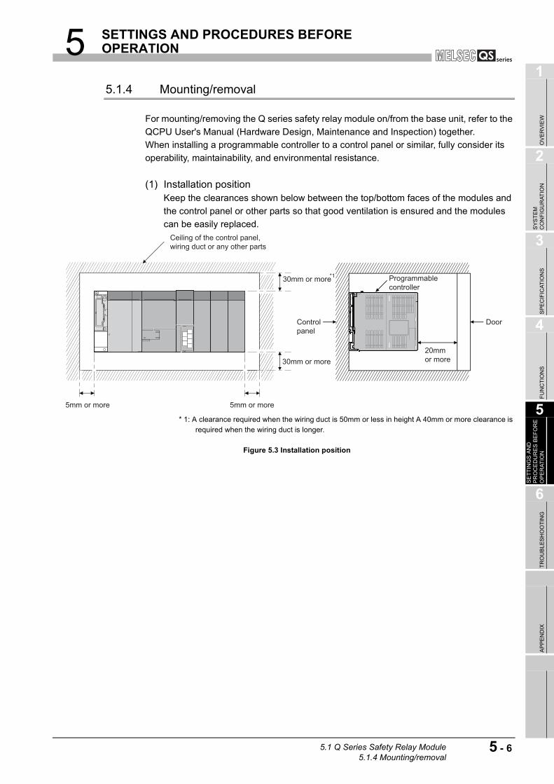
5 SETTINGS AND PROCEDURES BEFORE OPERATION
1
OV
ER
VIE
W
2
SY
ST
EM
C
ON
FIG
UR
AT
ION
3
SP
EC
IFIC
AT
ION
S
4
FU
NC
TIO
NS
5
SE
TT
ING
S A
ND
P
RO
CE
DU
RE
S B
EF
OR
E
OP
ER
AT
ION
6
TR
OU
BL
ES
HO
OT
ING
AP
PE
ND
IX
5.1.4 Mounting/removal
For mounting/removing the Q series safety relay module on/from the base unit, refer to the
QCPU User's Manual (Hardware Design, Maintenance and Inspection) together.
When installing a programmable controller to a control panel or similar, fully consider its
operability, maintainability, and environmental resistance.
(1) Installation positionKeep the clearances shown below between the top/bottom faces of the modules and
the control panel or other parts so that good ventilation is ensured and the modules
can be easily replaced.
* 1: A clearance required when the wiring duct is 50mm or less in height A 40mm or more clearance is required when the wiring duct is longer.
Figure 5.3 Installation position
*1
Ceiling of the control panel, wiring duct or any other parts
5mm or more 5mm or more
30mm or more
30mm or more20mm or more
Programmable controller
DoorControl panel
5.1 Q Series Safety Relay Module5.1.4 Mounting/removal
5 - 6
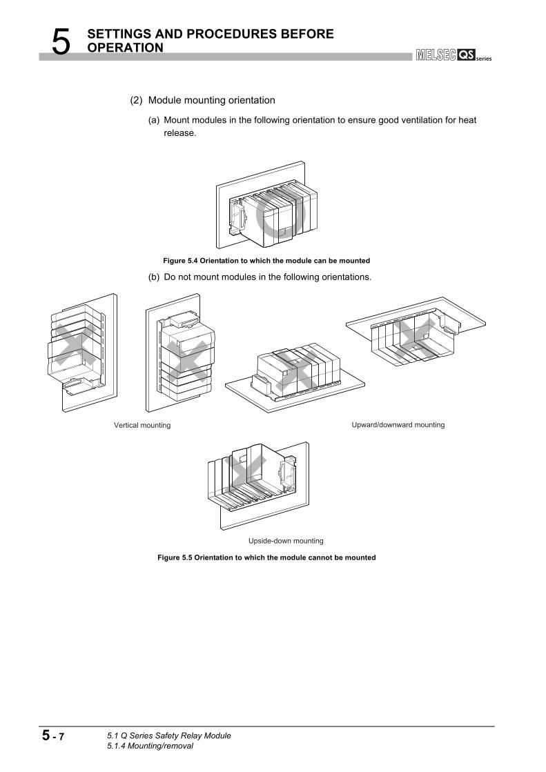
5 SETTINGS AND PROCEDURES BEFORE OPERATION
(2) Module mounting orientation
(a) Mount modules in the following orientation to ensure good ventilation for heat
release.
(b) Do not mount modules in the following orientations.
Figure 5.4 Orientation to which the module can be mounted
Figure 5.5 Orientation to which the module cannot be mounted
Vertical mounting Upward/downward mounting
Upside-down mounting
5 - 7 5.1 Q Series Safety Relay Module5.1.4 Mounting/removal
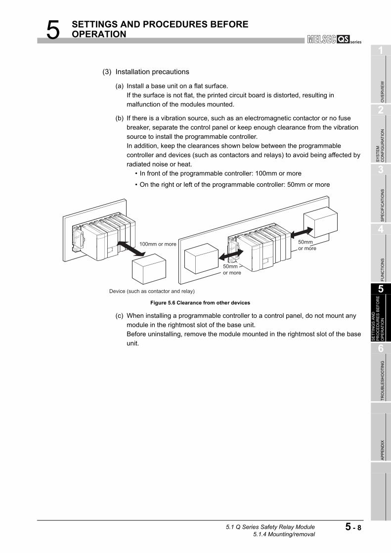
5 SETTINGS AND PROCEDURES BEFORE OPERATION
1
OV
ER
VIE
W
2
SY
ST
EM
C
ON
FIG
UR
AT
ION
3
SP
EC
IFIC
AT
ION
S
4
FU
NC
TIO
NS
5
SE
TT
ING
S A
ND
P
RO
CE
DU
RE
S B
EF
OR
E
OP
ER
AT
ION
6
TR
OU
BL
ES
HO
OT
ING
AP
PE
ND
IX
(3) Installation precautions
(a) Install a base unit on a flat surface.
If the surface is not flat, the printed circuit board is distorted, resulting in
malfunction of the modules mounted.
(b) If there is a vibration source, such as an electromagnetic contactor or no fuse
breaker, separate the control panel or keep enough clearance from the vibration
source to install the programmable controller.
In addition, keep the clearances shown below between the programmable
controller and devices (such as contactors and relays) to avoid being affected by
radiated noise or heat.
• In front of the programmable controller: 100mm or more
• On the right or left of the programmable controller: 50mm or more
(c) When installing a programmable controller to a control panel, do not mount any
module in the rightmost slot of the base unit.
Before uninstalling, remove the module mounted in the rightmost slot of the base
unit.
Figure 5.6 Clearance from other devices
50mm or more
50mm or more
Device (such as contactor and relay)
100mm or more
5.1 Q Series Safety Relay Module5.1.4 Mounting/removal
5 - 8
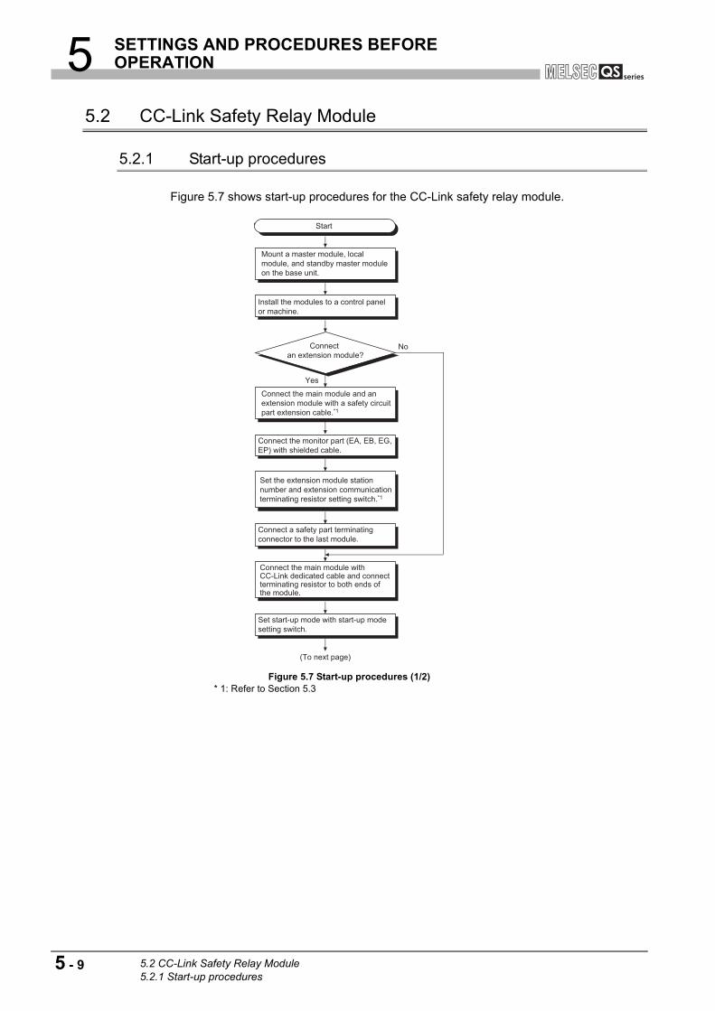
5 SETTINGS AND PROCEDURES BEFORE OPERATION
5.2 CC-Link Safety Relay Module
5.2.1 Start-up procedures
Figure 5.7 shows start-up procedures for the CC-Link safety relay module.
Figure 5.7 Start-up procedures (1/2) * 1: Refer to Section 5.3
Yes
No
Start
Install the modules to a control panel or machine.
Set the extension module station number and extension communication terminating resistor setting switch.*1
Connect the main module and an extension module with a safety circuit part extension cable.*1
Mount a master module, local module, and standby master module on the base unit.
Connect the main module with CC-Link dedicated cable and connect terminating resistor to both ends of the module.
Connect an extension module?
Connect the monitor part (EA, EB, EG, EP) with shielded cable.
Connect a safety part terminating connector to the last module.
Set start-up mode with start-up mode setting switch.
(To next page)
5 - 9 5.2 CC-Link Safety Relay Module5.2.1 Start-up procedures

5 SETTINGS AND PROCEDURES BEFORE OPERATION
1
OV
ER
VIE
W
2
SY
ST
EM
C
ON
FIG
UR
AT
ION
3
SP
EC
IFIC
AT
ION
S
4
FU
NC
TIO
NS
5
SE
TT
ING
S A
ND
P
RO
CE
DU
RE
S B
EF
OR
E
OP
ER
AT
ION
6
TR
OU
BL
ES
HO
OT
ING
AP
PE
ND
IX
Figure 5.7 Start-up procedures (2/2)
POINT
When powering ON the system, make sure to power ON the safety power supply
first, and then the module power supply.
If the module power supply is powered ON first, monitor signals cannot be read
properly.
For details, refer to Section 6.2.
Start-up modeAuto mode
Manual mode
Start-up modeAuto mode
Manual mode
Check the wiring and settings.
Power-ON
Turn ON the start-up switch.
Check the operating status with LED and others.
End
Connect the start-up switch between XS0 and XS1.
(From previous page)
Connect normally closed contact of the electromagnetic switch to off check.
Yes
No
Connect electromagnetic switch to output?
5.2 CC-Link Safety Relay Module5.2.1 Start-up procedures
5 - 10
5 SETTINGS AND PROCEDURES BEFORE OPERATION
5.2.2 Handling precautions
This section explains handling precautions for the CC-Link safety relay module.
(1) Mounting DIN railWhen mounting a DIN rail, pay attention to the following:
(a) Applicable DIN rail model (JIS C 2812 compliant)
TH35-7.5Fe
TH35-7.5Al
(b) DIN rail mounting screw interval
Mount the DIN rail with screws at intervals of 200mm or less.
(c) DIN rail fixing bracket
Securely fix a module with a DIN rail fixing bracket.
WARNING ● Do not touch the terminals while power is on.
Doing so could result in electric shock.
● Turn off all phases of the external supply power used in the
system when cleaning the module or retightening the
terminal block mounting screws.
Not doing so could result in electric shock.
Tighten a terminal block mounting screw within the specified
torque range.
If the terminal block mounting screw is too loose, it may
cause a short-circuit, fire or malfunctions.
If too tight, it may damage the screw and/or the module,
resulting in a drop of the screw or module, a short circuit or
malfunctions.
CAUTION ● Be sure there are no foreign substances such as sawdust or
wiring debris inside the module.
Such debris could cause a fire, failure, or malfunctions.
● Do not disassemble or remodel the module.
Doing so could cause a failure, malfunctions, injury, or fire.
If the product is repaired or remodeled by other than the
specified FA centers or us, the warranty is not covered.
● Do not directly touch the module's conductive parts or
electronic components.
Doing so may cause malfunctions or a failure.
● When disposing of this product, treat it as industrial waste.
5 - 11 5.2 CC-Link Safety Relay Module5.2.2 Handling precautions

5 SETTINGS AND PROCEDURES BEFORE OPERATION
1
OV
ER
VIE
W
2
SY
ST
EM
C
ON
FIG
UR
AT
ION
3
SP
EC
IFIC
AT
ION
S
4
FU
NC
TIO
NS
5
SE
TT
ING
S A
ND
P
RO
CE
DU
RE
S B
EF
OR
E
OP
ER
AT
ION
6
TR
OU
BL
ES
HO
OT
ING
AP
PE
ND
IX
5.2.3 Part names and settings
This section explains each part name of the CC-Link safety relay module.
Figure 5.8 CC-Link safety relay module
Table 5.2 Part names (1/2)
Number Name Description
1) Indicator LED
PW
Indicates status of the module power supply.
ON: Module power supply is supplied.
OFF: Module power supply is cut off or powered OFF with electric fuse.
ERR.
Indicates an error of the station.
Flash: A self-diagnostics error has occurred or safety power supply is cut
off.
OFF: Normal
L RUN
Indicates communication status of the CC-Link system.
ON: Normal communication
OFF: Communication is cut off (time over error).
SD ON: During data transmission
RD ON: During data reception
L ERR.
Indicates a communication error in the CC-Link system.
ON: A value set with station number setting switch or
transmission speed setting switch is out of range.
Flashing regularly: The station number setting switch or transmission
speed setting switch is changed during operation.
Flashing irregularly: A terminating resistor is not attached, is attached
wrongly or is influenced by noise.
OFF: Normal communication
S PW
Indicates the status of the safety power supply.
ON: Safety power supply is supplied.
OFF: Safety power supply is cut off or powered off with an electric fuse.
1)
7)11)
3)6)
8)
2)
5)
1)
9)
10)
4)
6)
5.2 CC-Link Safety Relay Module5.2.3 Part names and settings
5 - 12

5 SETTINGS AND PROCEDURES BEFORE OPERATION
Table 5.2 Part names (2/2)
Number Name Description
1) Indicator LED
Z
Indicates status of safety output Z.
ON:
OFF:
Safety output is generated (both K0 and K1 are ON).
Safety output is not generated.
X0 Indicates status of safety input (X0, X1).
X1ON:
OFF:
Safety output is generated.
Safety output is not generated.
K0
Indicates operating status of the internal safety relay K0 (coil status of K0).
ON: Operating status of the internal safety relay K0 is ON.
OFF: Operating status of the internal safety relay K0 is OFF.
K1
Indicates operating status of the internal safety relay K1 (coil status of K1).
ON: Operating status of the internal safety relay K1 is ON.
OFF: Operating status of the internal safety relay K1 is OFF.
2)CC-Link part, extension communication part
terminal block
DA, DB, DG: Data terminal for CC-Link cable
SLD: Shielding wire terminal of CC-Link cable
EA, EB, EG: Data terminal for extension communication
EP: Power supply terminal for extension module
3) Module power supply part terminal block+ 24V: Module power supply + 24V terminal
24G: Module power supply 24G terminal
4) Safety input part terminal block
X0X0: Safety input X0 input terminal
COM: Safety input X0 COM terminal
X1X1: Safety input X1 input terminal
COM: Safety input X1 COM terminal
5)Safety power supply, start-up
part terminal blockXS
XS0, XS1: Start-up off check terminal
+ 24V: Safety power supply + 24V terminal
24G: Safety power supply 24G terminal
6) Safety output part terminal block
Z00, Z01: Safety relay output terminal
Z10, Z11: Safety relay output terminal
Z20, Z21: Safety relay output terminal
7)
CC-Link transmission speed
terminating resistor setting
switch
1 to 4
A switch for setting transmission speed of the CC-Link system and if
terminating resistor is attached to the CC-Link system or not
•Transmission speed setting (Switch number from 1 to 3)
Set the transmission speed within the range from 0 to 4.
•Setting if CC-Link terminating resistor is attached or not (Switch number 4)
Setting switch LT
ON: Terminating resistor is attached.
OFF: Terminating resistor is not attached.
8)CC-Link station number setting
switchSTATION No.
A switch for setting the station number of CC-Link system
•Set tens place of the station number with " 10" of "STATION No.".
•Set ones place of the station number with " 1" of "STATION No.".
Set a station number within the range from 1 to 64.
(Repeat use of a station number is not possible.)
9) Start-up mode setting switch
A switch for setting start-up mode
"A" side: Auto mode
"M" side: Manual mode
10) Safety part extension connector OUT A connector for connecting an extension module
11) Serial number display A serial number same as the one shown on the rating plate
SettingSetting switch status (B RATE) Transmission
speed4 2 1
0 OFF OFF OFF 156kbps
1 OFF OFF ON 625kbps
2 OFF ON OFF 2.5Mbps
3 OFF ON ON 5Mbps
4 ON OFF OFF 10Mbps
5 - 13 5.2 CC-Link Safety Relay Module5.2.3 Part names and settings
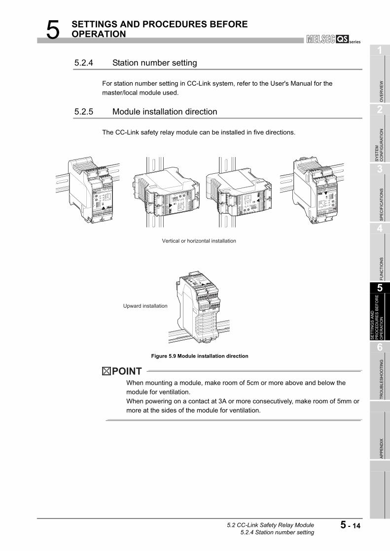
5 SETTINGS AND PROCEDURES BEFORE OPERATION
1
OV
ER
VIE
W
2
SY
ST
EM
C
ON
FIG
UR
AT
ION
3
SP
EC
IFIC
AT
ION
S
4
FU
NC
TIO
NS
5
SE
TT
ING
S A
ND
P
RO
CE
DU
RE
S B
EF
OR
E
OP
ER
AT
ION
6
TR
OU
BL
ES
HO
OT
ING
AP
PE
ND
IX
5.2.4 Station number setting
For station number setting in CC-Link system, refer to the User's Manual for the
master/local module used.
5.2.5 Module installation direction
The CC-Link safety relay module can be installed in five directions.
Figure 5.9 Module installation direction
POINT
When mounting a module, make room of 5cm or more above and below the
module for ventilation.
When powering on a contact at 3A or more consecutively, make room of 5mm or
more at the sides of the module for ventilation.
Upward installation
Vertical or horizontal installation
5.2 CC-Link Safety Relay Module5.2.4 Station number setting
5 - 14

5 SETTINGS AND PROCEDURES BEFORE OPERATION
5.3 Extension Safety Relay Module
5.3.1 Start-up procedures
Figure 5.10 shows start-up procedures for the extension safety relay module.
Figure 5.10 Start-up procedures (1/2)
Yes
No
Start
Connect a safety circuit part
terminating connector to the last
module.
Mount a module on a DIN rail or
control panel.
Connect safety circuit part extension
cable to the extension connector on
the front of the module (IN side).
Connect more
extension modules?
Set start-up mode with start-up mode
setting switch.
Set the terminating resistor switch
for extension communication.
Set the station number of extension
module communication.
Connect the monitor part (EA, EB, EG, EP) with shielded cable.
(To next page)
5 - 15 5.3 Extension Safety Relay Module5.3.1 Start-up procedures
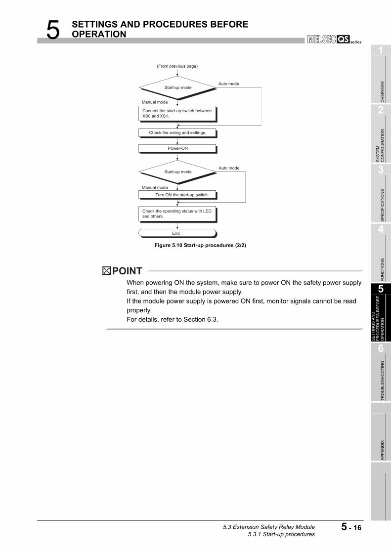
5 SETTINGS AND PROCEDURES BEFORE OPERATION
1
OV
ER
VIE
W
2
SY
ST
EM
C
ON
FIG
UR
AT
ION
3
SP
EC
IFIC
AT
ION
S
4
FU
NC
TIO
NS
5
SE
TT
ING
S A
ND
P
RO
CE
DU
RE
S B
EF
OR
E
OP
ER
AT
ION
6
TR
OU
BL
ES
HO
OT
ING
AP
PE
ND
IX
Figure 5.10 Start-up procedures (2/2)
POINT
When powering ON the system, make sure to power ON the safety power supply
first, and then the module power supply.
If the module power supply is powered ON first, monitor signals cannot be read
properly.
For details, refer to Section 6.3.
Connect the start-up switch between
XS0 and XS1.
Start-up mode
Start-up mode
Auto mode
Auto mode
Manual mode
Manual mode
Check the wiring and settings.
Power-ON
Turn ON the start-up switch.
Check the operating status with LED
and others.
End
(From previous page)
5.3 Extension Safety Relay Module5.3.1 Start-up procedures
5 - 16

5 SETTINGS AND PROCEDURES BEFORE OPERATION
5.3.2 Handling precautions
This section explains handling precautions for the extension safety relay module.
(1) Mounting DIN railWhen mounting a DIN rail, pay attention to the following:
(a) Applicable DIN rail model (JIS C 2812 compliant)
TH35-7.5Fe
TH35-7.5Al
(b) DIN rail mounting screw interval
Mount the DIN rail with screws at intervals of 200mm or less.
(c) DIN rail fixing bracket
Securely fix a module with a DIN rail fixing bracket.
WARNING ● Do not touch the terminals while power is on.
Doing so could result in electric shock.
● Turn off all phases of the external supply power used in the
system when cleaning the module or retightening the
terminal block mounting screws.
Not doing so could result in electric shock.
Tighten a terminal block mounting screw within the specified
torque range.
If the terminal block mounting screw is too loose, it may
cause a short-circuit, fire or malfunctions.
If too tight, it may damage the screw and/or the module,
resulting in a drop of the screw or module, a short circuit or
malfunctions.
● Use an extension module whose input type is the same as
that of the main module. The modules having different input
types (input P and N types) cannot be connected.
CAUTION ● Be sure there are no foreign substances such as sawdust or
wiring debris inside the module.
Such debris could cause a fire, failure, or malfunctions.
● Do not disassemble or remodel the module.
Doing so could cause a failure, malfunctions, injury, or fire.
If the product is repaired or remodeled by other than the
specified FA centers or us, the warranty is not covered.
● Do not directly touch the module's conductive parts or
electronic components.
Doing so may cause malfunctions or a failure.
● When disposing of this product, treat it as industrial waste.
5 - 17 5.3 Extension Safety Relay Module5.3.2 Handling precautions
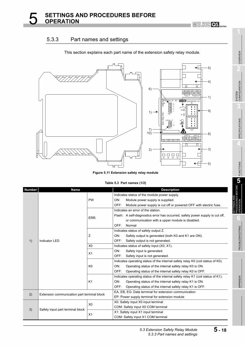
5 SETTINGS AND PROCEDURES BEFORE OPERATION
1
OV
ER
VIE
W
2
SY
ST
EM
C
ON
FIG
UR
AT
ION
3
SP
EC
IFIC
AT
ION
S
4
FU
NC
TIO
NS
5
SE
TT
ING
S A
ND
P
RO
CE
DU
RE
S B
EF
OR
E
OP
ER
AT
ION
6
TR
OU
BL
ES
HO
OT
ING
AP
PE
ND
IX
5.3.3 Part names and settings
This section explains each part name of the extension safety relay module.
Figure 5.11 Extension safety relay module
Table 5.3 Part names (1/2)
Number Name Description
1) Indicator LED
PW
Indicates status of the module power supply.
ON: Module power supply is supplied.
OFF: Module power supply is cut off or powered OFF with electric fuse.
ERR.
Indicates an error of the station.
Flash: A self-diagnostics error has occurred, safety power supply is cut off,
or communication with a upper module is disabled.
OFF: Normal
Z
Indicates status of safety output Z.
ON:
OFF:
Safety output is generated (both K0 and K1 are ON).
Safety output is not generated.
X0 Indicates status of safety input (X0, X1).
X1ON:
OFF:
Safety input is generated.
Safety input is not generated.
K0
Indicates operating status of the internal safety relay K0 (coil status of K0).
ON: Operating status of the internal safety relay K0 is ON.
OFF: Operating status of the internal safety relay K0 is OFF.
K1
Indicates operating status of the internal safety relay K1 (coil status of K1).
ON: Operating status of the internal safety relay K1 is ON.
OFF: Operating status of the internal safety relay K1 is OFF.
2) Extension communication part terminal blockEA, EB, EG: Data terminal for extension communication
EP: Power supply terminal for extension module
3) Safety input part terminal block
X0X0: Safety input X0 input terminal
COM: Safety input X0 COM terminal
X1X1: Safety input X1 input terminal
COM: Safety input X1 COM terminal
1)
7)10)
5)
6)
2)
4)
1)
8)
9)
3)
5)
5.3 Extension Safety Relay Module5.3.3 Part names and settings
5 - 18
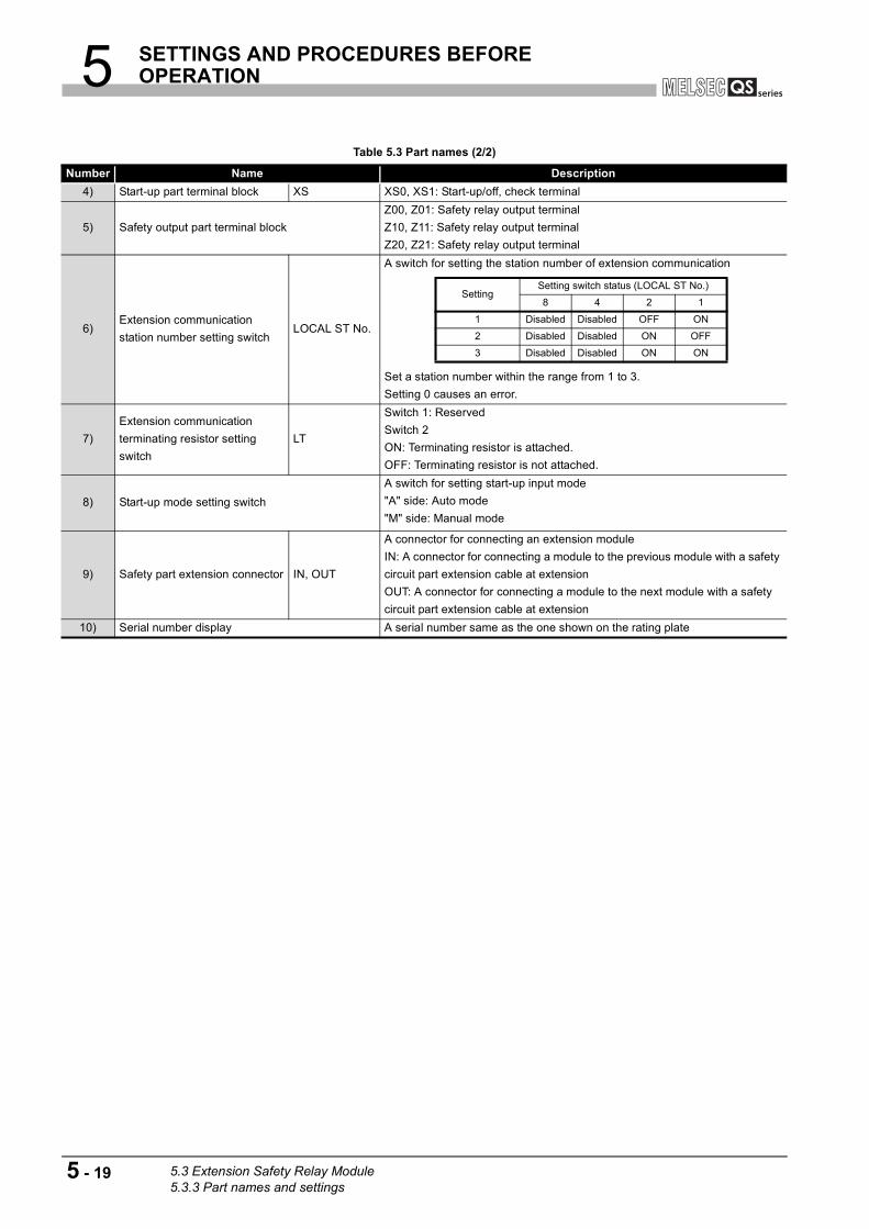
5 SETTINGS AND PROCEDURES BEFORE OPERATION
Table 5.3 Part names (2/2)
Number Name Description
4) Start-up part terminal block XS XS0, XS1: Start-up/off, check terminal
5) Safety output part terminal block
Z00, Z01: Safety relay output terminal
Z10, Z11: Safety relay output terminal
Z20, Z21: Safety relay output terminal
6)Extension communication
station number setting switchLOCAL ST No.
A switch for setting the station number of extension communication
Set a station number within the range from 1 to 3.
Setting 0 causes an error.
7)
Extension communication
terminating resistor setting
switch
LT
Switch 1: Reserved
Switch 2
ON: Terminating resistor is attached.
OFF: Terminating resistor is not attached.
8) Start-up mode setting switch
A switch for setting start-up input mode
"A" side: Auto mode
"M" side: Manual mode
9) Safety part extension connector IN, OUT
A connector for connecting an extension module
IN: A connector for connecting a module to the previous module with a safety
circuit part extension cable at extension
OUT: A connector for connecting a module to the next module with a safety
circuit part extension cable at extension
10) Serial number display A serial number same as the one shown on the rating plate
SettingSetting switch status (LOCAL ST No.)
8 4 2 1
1 Disabled Disabled OFF ON
2 Disabled Disabled ON OFF
3 Disabled Disabled ON ON
5 - 19 5.3 Extension Safety Relay Module5.3.3 Part names and settings
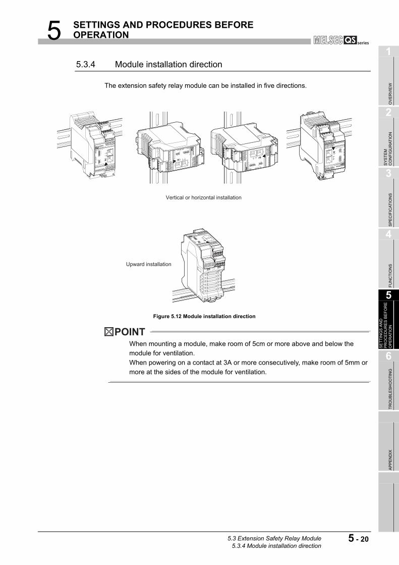
5 SETTINGS AND PROCEDURES BEFORE OPERATION
1
OV
ER
VIE
W
2
SY
ST
EM
C
ON
FIG
UR
AT
ION
3
SP
EC
IFIC
AT
ION
S
4
FU
NC
TIO
NS
5
SE
TT
ING
S A
ND
P
RO
CE
DU
RE
S B
EF
OR
E
OP
ER
AT
ION
6
TR
OU
BL
ES
HO
OT
ING
AP
PE
ND
IX
5.3.4 Module installation direction
The extension safety relay module can be installed in five directions.
Figure 5.12 Module installation direction
POINT
When mounting a module, make room of 5cm or more above and below the
module for ventilation.
When powering on a contact at 3A or more consecutively, make room of 5mm or
more at the sides of the module for ventilation.
Vertical or horizontal installation
Upward installation
5.3 Extension Safety Relay Module5.3.4 Module installation direction
5 - 20
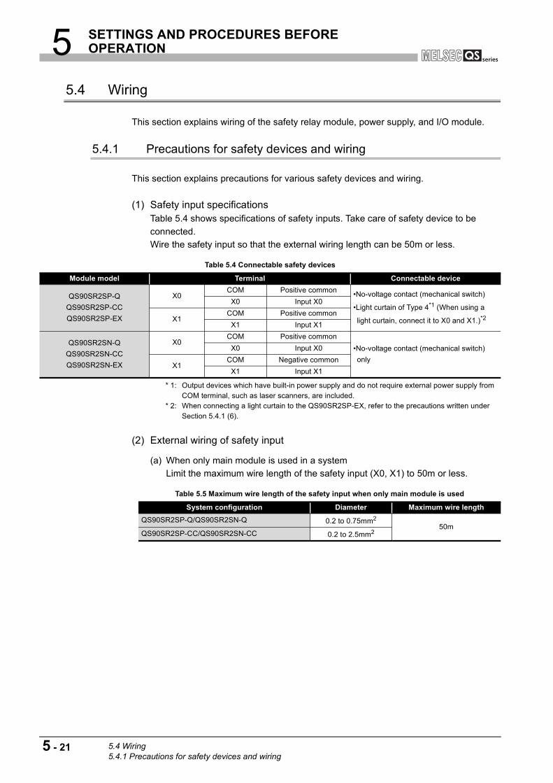
5 SETTINGS AND PROCEDURES BEFORE OPERATION
5.4 Wiring
This section explains wiring of the safety relay module, power supply, and I/O module.
5.4.1 Precautions for safety devices and wiring
This section explains precautions for various safety devices and wiring.
(1) Safety input specificationsTable 5.4 shows specifications of safety inputs. Take care of safety device to be
connected.
Wire the safety input so that the external wiring length can be 50m or less.
* 1: Output devices which have built-in power supply and do not require external power supply from COM terminal, such as laser scanners, are included.
* 2: When connecting a light curtain to the QS90SR2SP-EX, refer to the precautions written under Section 5.4.1 (6).
(2) External wiring of safety input
(a) When only main module is used in a system
Limit the maximum wire length of the safety input (X0, X1) to 50m or less.
Table 5.4 Connectable safety devices
Module model Terminal Connectable device
QS90SR2SP-Q
QS90SR2SP-CC
QS90SR2SP-EX
X0COM Positive common
•No-voltage contact (mechanical switch)
•Light curtain of Type 4*1 (When using a
light curtain, connect it to X0 and X1.)*2
X0 Input X0
X1COM Positive common
X1 Input X1
QS90SR2SN-Q
QS90SR2SN-CC
QS90SR2SN-EX
X0COM Positive common
•No-voltage contact (mechanical switch)
only
X0 Input X0
X1COM Negative common
X1 Input X1
Table 5.5 Maximum wire length of the safety input when only main module is used
System configuration Diameter Maximum wire length
QS90SR2SP-Q/QS90SR2SN-Q 0.2 to 0.75mm2
50mQS90SR2SP-CC/QS90SR2SN-CC 0.2 to 2.5mm2
5 - 21 5.4 Wiring5.4.1 Precautions for safety devices and wiring
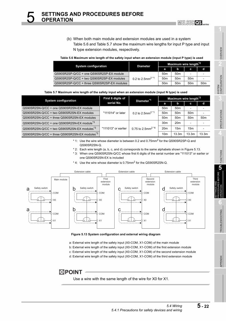
5 SETTINGS AND PROCEDURES BEFORE OPERATION
1
OV
ER
VIE
W
2
SY
ST
EM
C
ON
FIG
UR
AT
ION
3
SP
EC
IFIC
AT
ION
S
4
FU
NC
TIO
NS
5
SE
TT
ING
S A
ND
P
RO
CE
DU
RE
S B
EF
OR
E
OP
ER
AT
ION
6
TR
OU
BL
ES
HO
OT
ING
AP
PE
ND
IX
(b) When both main module and extension modules are used in a system
Table 5.6 and Table 5.7 show the maximum wire lengths for input P type and input
N type extension modules, respectively.
* 1: Use the wire whose diameter is between 0.2 and 0.75mm2 for the QS90SR2SP-Q and QS90SR2SN-Q.
* 2: Each wire length (a, b, c, and d) corresponds to the same alphabets shown in Figure 5.13. * 3: When one QS90SR2SN-Q/CC whose first 6 digits of the serial number are "111013" or earlier or
one QS90SR2SN-EX is included
* 4: Use the wire whose diameter is 0.75mm2 for the QS90SR2SN-Q.
Figure 5.13 System configuration and external wiring diagram
POINT
Use a wire with the same length of the wire for X0 for X1.
Table 5.6 Maximum wire length of the safety input when an extension module (input P type) is used
System configuration DiameterMaximum wire length*2
a b c d
QS90SR2SP-Q/CC + one QS90SR2SP-EX module
0.2 to 2.5mm2 *1
50m 50m - -
QS90SR2SP-Q/CC + two QS90SR2SP-EX modules 50m 50m 50m -
QS90SR2SP-Q/CC + three QS90SR2SP-EX modules 50m 50m 50m 50m
Table 5.7 Maximum wire length of the safety input when an extension module (input N type) is used
System configurationFirst 6 digits of
serial No.Diameter*1 Maximum wire length*2
a b c d
QS90SR2SN-Q/CC + one QS90SR2SN-EX module
"111014" or later 0.2 to 2.5mm2 *1
50m 50m - -
QS90SR2SN-Q/CC + two QS90SR2SN-EX modules 50m 50m 50m -
QS90SR2SN-Q/CC + three QS90SR2SN-EX modules 50m 50m 50m 50m
QS90SR2SN-Q/CC + one QS90SR2SN-EX module*3
"111013" or earlier 0.75 to 2.5mm2 *4
30m 20m - -
QS90SR2SN-Q/CC + two QS90SR2SN-EX modules*3 20m 15m 15m -
QS90SR2SN-Q/CC + three QS90SR2SN-EX modules*3 10m 13.3m 13.3m 13.3m
a: External wire length of the safety input (X0-COM, X1-COM) of the main module
b: External wire length of the safety input (X0-COM, X1-COM) of the first extension module
c: External wire length of the safety input (X0-COM, X1-COM) of the second extension module
d: External wire length of the safety input (X0-COM, X1-COM) of the third extension module
a b c d
a b c d
First extension
module
Extension cable Extension cable Extension cable
Second extension
module
Third extension
module
Main module
Safety switch Safety switch Safety switch Safety switch
COM
X0
X1
COM
COM
X0
X1
COM
COM
X0
X1
COM
COM
X0
X1
COM
5.4 Wiring5.4.1 Precautions for safety devices and wiring
5 - 22
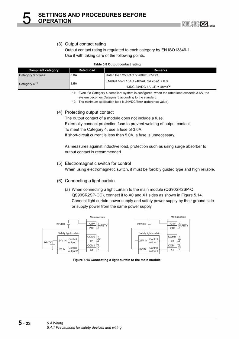
5 SETTINGS AND PROCEDURES BEFORE OPERATION
(3) Output contact ratingOutput contact rating is regulated to each category by EN ISO13849-1.
Use it with taking care of the following points.
* 1: Even if a Category 4 compliant system is configured, when the rated load exceeds 3.6A, the system becomes Category 3 according to the standard.
* 2: The minimum application load is 24VDC/5mA (reference value).
(4) Protecting output contactThe output contact of a module does not include a fuse.
Externally connect protection fuse to prevent welding of output contact.
To meet the Category 4, use a fuse of 3.6A.
If short-circuit current is less than 5.0A, a fuse is unnecessary.
As measures against inductive load, protection such as using surge absorber to
output contact is recommended.
(5) Electromagnetic switch for controlWhen using electromagnetic switch, it must be forcibly guided type and high reliable.
(6) Connecting a light curtain
(a) When connecting a light curtain to the main module (QS90SR2SP-Q,
QS90SR2SP-CC), connect it to X0 and X1 sides as shown in Figure 5.14.
Connect light curtain power supply and safety power supply by their ground side
or supply power from the same power supply.
Figure 5.14 Connecting a light curtain to the main module
Table 5.8 Output contact rating
Compliant category Rated load Remarks
Category 3 or less 5.0A Rated load 250VAC 50/60Hz 30VDC
EN60947-5-1 15AC 240VAC 2A cos = 0.3
13DC 24VDC 1A L/R = 48ms*2Category 4 *1 3.6A
COM1
X1
X0
24G
+24V24VDC
24VDC
COM0
24V IN
0V IN Control
output 2
Control
output 1
Safety light curtain
SAFETY
X0
X1COM1
X1
X0
24G
+24V24VDC
COM0
24V IN
0V IN Control
output 2
Control
output 1
Safety light curtain
SAFETY
X0
X1
Main moduleMain module
5 - 23 5.4 Wiring5.4.1 Precautions for safety devices and wiring

5 SETTINGS AND PROCEDURES BEFORE OPERATION
1
OV
ER
VIE
W
2
SY
ST
EM
C
ON
FIG
UR
AT
ION
3
SP
EC
IFIC
AT
ION
S
4
FU
NC
TIO
NS
5
SE
TT
ING
S A
ND
P
RO
CE
DU
RE
S B
EF
OR
E
OP
ER
AT
ION
6
TR
OU
BL
ES
HO
OT
ING
AP
PE
ND
IX
(b) When a light curtain is connected to the extension module (QS90SR2SP-EX),
safety shutdown from the main module may be disabled depending on the wiring
configuration.
Wire the cables referring to the connection diagram shown in Figure 5.15 and
according to the precautions below.
Figure 5.15 Connecting a light curtain to the extension module
Safety shutdown from the main module turns off inputs by cutting off input power
supplied to the COM terminal of the extension module.
That is, if the wiring is configured so that power of the light curtain is supplied from
the COM terminal of the extension module, power supply of the light curtain turns
off and outputs of the extension module stops consequently in the event of the
safety shutdown.
1) Precautions for selecting power supply
Power supply input of a light curtain will be connected to the COM terminal of
the extension module. Select a light curtain compatible with the specifications
for the COM terminal and X0/X1 terminals of the extension module.
* * 1: Current consumption = COM terminal output current (500[mA]) - ((X0 terminal input current
(40[mA]) + X1 terminal input current (40[mA])) Number of light curtains
The number of light curtains means the number of light curtains connected in one system.One system means the system configured with one main module and one or more extension module(s).
Specifications for the COM terminal of the extension module
Rated voltage: 23 10% [V]
Output current: Maximum 500[mA]
Specifications for the X0 and X1 terminals of the extension module
ON voltage: 20.0[V] or more
OFF voltage/current : 2.4[V] or less/2.0[mA] or less
Input current: Maximum 40[mA]
Input voltage: Maximum 26.4[V]
Table 5.9 Specifications for selectable light curtains
Rated voltage 23 10 [V]
Total amount of current consumption of light
curtain (receiver)*1One light curtain is connected: 420[mA] or less
Two light curtains are connected: 340[mA] or less
ON voltage 20.0[V] or more
OFF voltage/current 2.4[V] or less/2.0[mA] or less
Controloutput 1
Controloutput 2
Safety light curtain
To the main module 24G terminal 0V IN
24V INCOM0
X0
X1
COM1
Extension module
5.4 Wiring5.4.1 Precautions for safety devices and wiring
5 - 24

5 SETTINGS AND PROCEDURES BEFORE OPERATION
2) Precautions for selecting power supply
Power of a light curtain is supplied from power supply connected between
+24V(SAFETY) and 24G(SAFETY) of the main module via the COM terminal
of the extension module. If the current or voltage supplied from the COM
terminal is insufficient, operation of the light curtain cannot be guaranteed.
Select the power supply device which meets the following conditions.
Power supply output voltage : 24 10% [V]
Power supply output current : Main module current consumption (85[mA]) +
(Extension module current consumption (80[mA]) Number of extension
modules) + (Total amount of current consumption of light curtain*2) + ((X0
terminal input current (40[mA]) + X1 terminal input current (40[mA])) Number
of light curtains)[mA] or more * 2: Control output current is not included. If included, subtract the control output current amount.
[Calculation example]
A calculation example for the system with three extension modules and two
light curtains is shown below.
In the example, current consumption of each light curtain is assumed as
follows.
Current consumption of light curtain A (receiver): 120[mA]
Current consumption of light curtain B (receiver): 210[mA]
Safety relay module specifications
Main module current consumption: 85[mA]
Extension module current consumption: 80[mA]
X0/X1 terminal input current: 40[mA]
Power supply output current[mA] > 85[mA] + (80[mA] 3) + (120[mA] +
210[mA]) + ((40[mA] + 40[mA]) 2)
Power supply output current[mA] > 815[mA]
As a result of the calculation, it is concluded that power supply which has
output current 815[mA] or more is required for the system configuration in the
above example.
5 - 25 5.4 Wiring5.4.1 Precautions for safety devices and wiring

5 SETTINGS AND PROCEDURES BEFORE OPERATION
1
OV
ER
VIE
W
2
SY
ST
EM
C
ON
FIG
UR
AT
ION
3
SP
EC
IFIC
AT
ION
S
4
FU
NC
TIO
NS
5
SE
TT
ING
S A
ND
P
RO
CE
DU
RE
S B
EF
OR
E
OP
ER
AT
ION
6
TR
OU
BL
ES
HO
OT
ING
AP
PE
ND
IX
(c) Precautions for connecting a light curtain
When connecting a light curtain referring to the connection diagram shown in
Figure 5.15, pay attention to the following.
1) Light curtains cannot be connected to the main module and the extension
module respectively at the same. Only a switch*1 such as an emergency stop
can be connected as safety input of the main module.
2) Up to three extension modules can be connected to one main module. In this
case, however, up to two extension modules are available for connecting a
light curtain (one light curtain per module).
For the third extension module, only a switch*1 such as an emergency stop can
be connected.
3) Power supply of a light curtain is cut off by turning on (opening the contact of)
the switch which is connected to the input X0 and X1 of the main module.
Check the time required for the light curtain to restart in the specification and
provide an interlock until the restart of the light curtain is completed.
4) When connecting a switch to the X0 and X1 terminals of the main module, wire
the cables so that the cable length becomes within 10m for both between the
X0 and COM terminals and between the X1 and COM terminals. * 1: Switch means a device whose condition between the COM terminal and X0 or X1 terminal is
short-circuited when the switch is off (the contact is closed) and that has no load to develop voltage drop in the closed circuit.
5.4 Wiring5.4.1 Precautions for safety devices and wiring
5 - 26
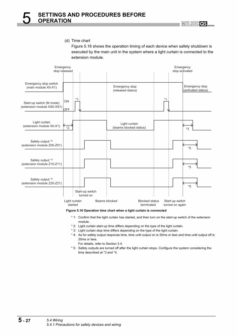
5 SETTINGS AND PROCEDURES BEFORE OPERATION
(d) Time chart
Figure 5.16 shows the operation timing of each device when safety shutdown is
executed by the main unit in the system where a light curtain is connected to the
extension module.
Figure 5.16 Operation time chart when a light curtain is connected
* 1: Confirm that the light curtain has started, and then turn on the start-up switch of the extension module.
* 2: Light curtain start-up time differs depending on the type of the light curtain. * 3: Light curtain stop time differs depending on the type of the light curtain. * 4: As for safety output response time, time until output on is 50ms or less and time until output off is
20ms or less.For details, refer to Section 3.4.
* 5: Safety outputs are turned off after the light curtain stops. Configure the system considering the time described at *3 and *4.
Safety output *4(extension module Z20-Z21)
Safety output *4(extension module Z10-Z11)
Safety output *4(extension module Z00-Z01)
Light curtain(extension module X0-X1)
Start-up switch (M mode)(extension module XS0-XS1)
Start-up switchturned on again
Blocked statusterminated
Beams blocked
*5
*5
*5
*3*2
OFF
ON *1*1
Emergency stop(released status)
Light curtain(beams blocked status)
Start-up switchturned on
Light curtainstarted
Emergency stop(activated status)
Emergencystop activated
Emergency stop released
Emergency stop switch(main module X0-X1)
5 - 27 5.4 Wiring5.4.1 Precautions for safety devices and wiring
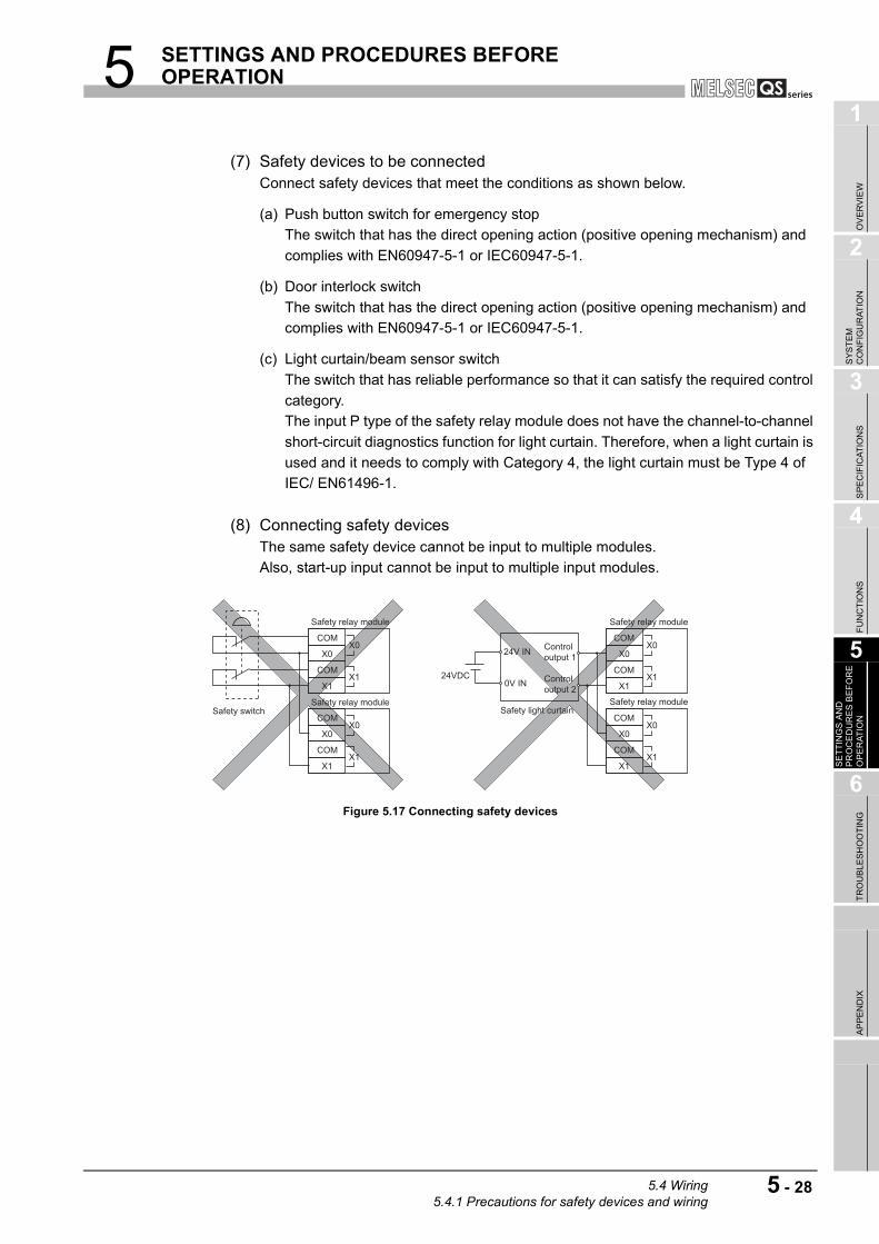
5 SETTINGS AND PROCEDURES BEFORE OPERATION
1
OV
ER
VIE
W
2
SY
ST
EM
C
ON
FIG
UR
AT
ION
3
SP
EC
IFIC
AT
ION
S
4
FU
NC
TIO
NS
5
SE
TT
ING
S A
ND
P
RO
CE
DU
RE
S B
EF
OR
E
OP
ER
AT
ION
6
TR
OU
BL
ES
HO
OT
ING
AP
PE
ND
IX
(7) Safety devices to be connectedConnect safety devices that meet the conditions as shown below.
(a) Push button switch for emergency stop
The switch that has the direct opening action (positive opening mechanism) and
complies with EN60947-5-1 or IEC60947-5-1.
(b) Door interlock switch
The switch that has the direct opening action (positive opening mechanism) and
complies with EN60947-5-1 or IEC60947-5-1.
(c) Light curtain/beam sensor switch
The switch that has reliable performance so that it can satisfy the required control
category.
The input P type of the safety relay module does not have the channel-to-channel
short-circuit diagnostics function for light curtain. Therefore, when a light curtain is
used and it needs to comply with Category 4, the light curtain must be Type 4 of
IEC/ EN61496-1.
(8) Connecting safety devices The same safety device cannot be input to multiple modules.
Also, start-up input cannot be input to multiple input modules.
Figure 5.17 Connecting safety devices
COM
X1
X0
COM24V IN
0V IN Control output 2
Control output 1
X0
X1
COM
X1
X0
COMX0
X1
COM
X1
X0
COMX0
X1
Safety relay module
Safety relay module
Safety relay module
Safety relay module
COM
X1
X0
COMX0
X1
24VDC
Safety switch Safety light curtain
5.4 Wiring5.4.1 Precautions for safety devices and wiring
5 - 28

5 SETTINGS AND PROCEDURES BEFORE OPERATION
(9) Safety stop and function stopWhen using safety relay module, ON/OFF operation is made with the function stop
according to control target. In this case, use it together with safety stop.
Since only function stop may not stop the system, not doing so may cause a
malfunction.
Connect safety devices to X0 and X1 sides and cut off the output on control target
side.
Figure 5.18 Safety stop and function stop
Safety switch
Control target
General relay
RY
Control part
Programmable controller, controller
Z00
Z01
Z10
Z11
Z20
Z21
Internalcircuit
M
Functionstop
Safetystop
Safety relay module
X1
X0COM
X0
X1COM
5 - 29 5.4 Wiring5.4.1 Precautions for safety devices and wiring

5 SETTINGS AND PROCEDURES BEFORE OPERATION
1
OV
ER
VIE
W
2
SY
ST
EM
C
ON
FIG
UR
AT
ION
3
SP
EC
IFIC
AT
ION
S
4
FU
NC
TIO
NS
5
SE
TT
ING
S A
ND
P
RO
CE
DU
RE
S B
EF
OR
E
OP
ER
AT
ION
6
TR
OU
BL
ES
HO
OT
ING
AP
PE
ND
IX
5.4.2 Spring clamp terminal block
(1) Method for connecting a cable to the spring clamp terminal block
(a) Connecting a cable
1) For module power supply part/safety power supply part/safety input part/safety
output part terminal block
While pressing the open/close button with a flathead screwdriver, insert a
cable into the insertion hole.
For use of bar terminals, the cable can be inserted without pressing the
open/close button.
Figure 5.19 Connecting a cable to module power supply/safety power supply part/safety input part/safety output part terminal block
2) For extension communication part terminal block
Insert a flathead screwdriver into the open/close button, and insert a cable into
the hole while pressing the driver.
For use of bar terminals, the cable can be inserted without pressing the
open/close button.
Figure 5.20 Connecting a cable to extension communication part terminal block
POINT
Pay attention when using a flathead screwdriver to push the open/close button of
the spring clamp terminal block. Failure to do so can result in an injury.
Insertion hole
Open/close button
Flathead screwdriver
Open/close button
Insertion hole
Flathead screwdriver
5.4 Wiring5.4.2 Spring clamp terminal block
5 - 30

5 SETTINGS AND PROCEDURES BEFORE OPERATION
(b) Disconnecting a cable
1) For module power supply part/safety power supply part/safety input part/safety
output part terminal block
While fully pressing the open/close button with a flathead screwdriver, pull out
the cable.
2) For extension communication part terminal block
While fully inserting a flathead screwdriver into the open/close button, pull out
the cable from the insertion hole.
(2) Method for processing the cable endThe cable strip length must be around 10mm.
If the cable is stripped too much, conductive part may stick out of the terminal block,
which leads to electric shock or short-circuit between adjacent terminal blocks.
If the stripped length is too short, sufficient contact may not be ensured.
Figure 5.21 Cable strip length
For use of bar terminals, pay attention to the following:
1) Select a bar terminal suitable for the cable size.
2) Use an appropriate crimp tool to crimp the bar terminal.
3) Insert the cable so that cable cores will stick out by 0 to 0.5mm from the sleeve
edge.
Figure 5.22 Bar terminal
4) Check an appearance of the bar terminal after crimping it. Do not use the
terminal if it is not crimped properly or the side is damaged (refer to Figure
5.23).
Figure 5.23 Example of incorrect bar terminal crimp
Around 10mm
Cable
Sleeve
ShellCable
0 to 0.5mm
Damaged Crushed edgeA cable is not inserted to a shell.
Stray wire
5 - 31 5.4 Wiring5.4.2 Spring clamp terminal block
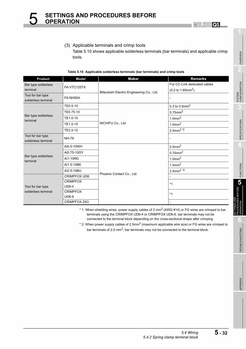
5 SETTINGS AND PROCEDURES BEFORE OPERATION
1
OV
ER
VIE
W
2
SY
ST
EM
C
ON
FIG
UR
AT
ION
3
SP
EC
IFIC
AT
ION
S
4
FU
NC
TIO
NS
5
SE
TT
ING
S A
ND
P
RO
CE
DU
RE
S B
EF
OR
E
OP
ER
AT
ION
6
TR
OU
BL
ES
HO
OT
ING
AP
PE
ND
IX
(3) Applicable terminals and crimp toolsTable 5.10 shows applicable solderless terminals (bar terminals) and applicable crimp
tools.
* 1: When shielding wires, power supply cables of 2 mm2 (AWG #14) or FG wires are crimped to bar terminals using the CRIMPFOX UD6-4 or CRIMPFOX UD6-6, bar terminals may not be connected to the terminal block depending on the cross-sectional shape after crimping.
* 2: When power supply cables of 2.5mm2 (maximum applicable wire size) or FG wires are crimped to
bar terminals of 2.5 mm2, bar terminals may not be connected to the terminal block.
Table 5.10 Applicable solderless terminals (bar terminals) and crimp tools
Product Model Maker Remarks
Bar type solderless
terminalFA-VTC125T9
Mitsubishi Electric Engineering Co., Ltd.
For CC-Link dedicated cables
(0.3 to 1.65mm2)
Tool for bar type
solderless terminalFA-NH65A -
Bar type solderless
terminal
TE0.5-10
NICHIFU Co., Ltd.
0.3 to 0.5mm2
TE0.75-10 0.75mm2
TE1.0-10 1.0mm2
TE1.5-10 1.5mm2
TE2.5-12 2.5mm2 *2
Tool for bar type
solderless terminalNH-79 -
Bar type solderless
terminal
AI0.5-10WH
Phoenix Contact Co., Ltd.
0.5mm2
AI0.75-10GY 0.75mm2
AI1-10RD 1.0mm2
AI1.5-10BK 1.5mm2
AI2.5-10BU 2.5mm2 *2
Tool for bar type
solderless terminal
CRIMPFOX UD6 -
CRIMPFOX
UD6-4*1
CRIMPFOX
UD6-6*1
CRIMPFOX ZA3 -
5.4 Wiring5.4.2 Spring clamp terminal block
5 - 32

5 SETTINGS AND PROCEDURES BEFORE OPERATION
5.4.3 Attaching/removing a terminal block
(1) Attaching a terminal block
(a) For Q series safety relay module
Insert a terminal block into the connector and tighten terminal block fixing screws
with a flathead screwdriver.
(b) For CC-Link safety relay module and extension safety relay module
As for the module power supply part/safety power supply part/safety input
part/safety output part terminal block, install the terminal block cover after the
insertion.
The terminal block cover cannot be installed if the terminal block is not fully
inserted.
Figure 5.24 Terminal block cover
(2) Removing a terminal block
(a) For Q series safety relay module
Loose the terminal block fixing screws with a flathead screwdriver, and pull out the
terminal block.
(b) For CC-Link safety relay module and extension safety relay module
As for the module power supply part/safety power supply part/safety input
part/safety output part terminal block, remove the terminal block cover before
pulling out the terminal block with a flathead screwdriver.
5.4.4 Precautions for handling CC-Link dedicated cable
This section explains precautions for handling the CC-Link dedicated cable.
Do not handle the cable in the following manner. Doing so may damage the cable.
• Squashing it with sharp tool
• Twisting it excessively
• Pulling it strongly (exceeding the allowable tensility)
• Treading it
• Placing an object on it
• Scratching a cable jacket
Terminal block cover
5 - 33 5.4 Wiring5.4.3 Attaching/removing a terminal block
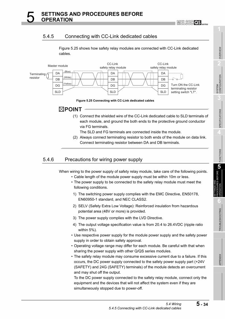
5 SETTINGS AND PROCEDURES BEFORE OPERATION
1
OV
ER
VIE
W
2
SY
ST
EM
C
ON
FIG
UR
AT
ION
3
SP
EC
IFIC
AT
ION
S
4
FU
NC
TIO
NS
5
SE
TT
ING
S A
ND
P
RO
CE
DU
RE
S B
EF
OR
E
OP
ER
AT
ION
6
TR
OU
BL
ES
HO
OT
ING
AP
PE
ND
IX
5.4.5 Connecting with CC-Link dedicated cables
Figure 5.25 shows how safety relay modules are connected with CC-Link dedicated
cables.
Figure 5.25 Connecting with CC-Link dedicated cables
POINT
(1) Connect the shielded wire of the CC-Link dedicated cable to SLD terminals of
each module, and ground the both ends to the protective ground conductor
via FG terminals.
The SLD and FG terminals are connected inside the module.
(2) Always connect terminating resistor to both ends of the module on data link.
Connect terminating resistor between DA and DB terminals.
5.4.6 Precautions for wiring power supply
When wiring to the power supply of safety relay module, take care of the following points.
• Cable length of the module power supply must be within 10m or less.
• The power supply to be connected to the safety relay module must meet the
following conditions.
1) The switching power supply complies with the EMC Directive, EN50178,
EN60950-1 standard, and NEC CLASS2.
2) SELV (Safety Extra Low Voltage): Reinforced insulation from hazardous
potential area (48V or more) is provided.
3) The power supply complies with the LVD Directive.
4) The output voltage specification value is from 20.4 to 26.4VDC (ripple ratio
within 5%).
• Use respective power supply for the module power supply and the safety power
supply in order to obtain safety approval.
• Operating voltage range may differ for each module. Be careful with that when
sharing the power supply with other Q/QS series modules.
• The safety relay module may consume excessive current due to a failure. If this
occurs, the DC power supply connected to the safety power supply part (+24V
(SAFETY) and 24G (SAFETY) terminals) of the module detects an overcurrent
and may shut off the output.
To the DC power supply connected to the safety relay module, connect only the
equipment and the devices that will not affect the system even if they are
simultaneously stopped due to power-off.
SLD
DG
DB
DA
SLD
DG
DB
DA
SLD
DG
DB
DATerminatingresistor
Turn ON the CC-Linkterminating resistorsetting switch "LT".
CC-Link safety relay module
CC-Link safety relay module
(Yellow)
(White)
(Blue)
Master module
5.4 Wiring5.4.5 Connecting with CC-Link dedicated cables
5 - 34
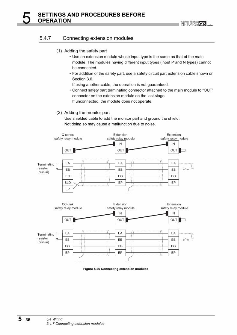
5 SETTINGS AND PROCEDURES BEFORE OPERATION
5.4.7 Connecting extension modules
(1) Adding the safety part • Use an extension module whose input type is the same as that of the main
module. The modules having different input types (input P and N types) cannot
be connected.
• For addition of the safety part, use a safety circuit part extension cable shown on
Section 3.6.
If using another cable, the operation is not guaranteed.
• Connect safety part terminating connector attached to the main module to “OUT”
connector on the extension module on the last stage.
If unconnected, the module does not operate.
(2) Adding the monitor partUse shielded cable to add the monitor part and ground the shield.
Not doing so may cause a malfunction due to noise.
Figure 5.26 Connecting extension modules
Extension safety relay module
Extension safety relay module
CC-Link safety relay module
OUT OUT
IN
OUT
IN
EP
EG
EB
EA
EP
EG
EB
EA
EP
EG
EB
EA
EP
EG
EB
EA
EP
EG
EB
EA
EA
EP
SLD
EG
EB
Extension safety relay module
Extension safety relay module
Terminatingresistor(built-in)
Terminatingresistor(built-in)
Q series safety relay module
OUT OUT
IN
OUT
IN
5 - 35 5.4 Wiring5.4.7 Connecting extension modules
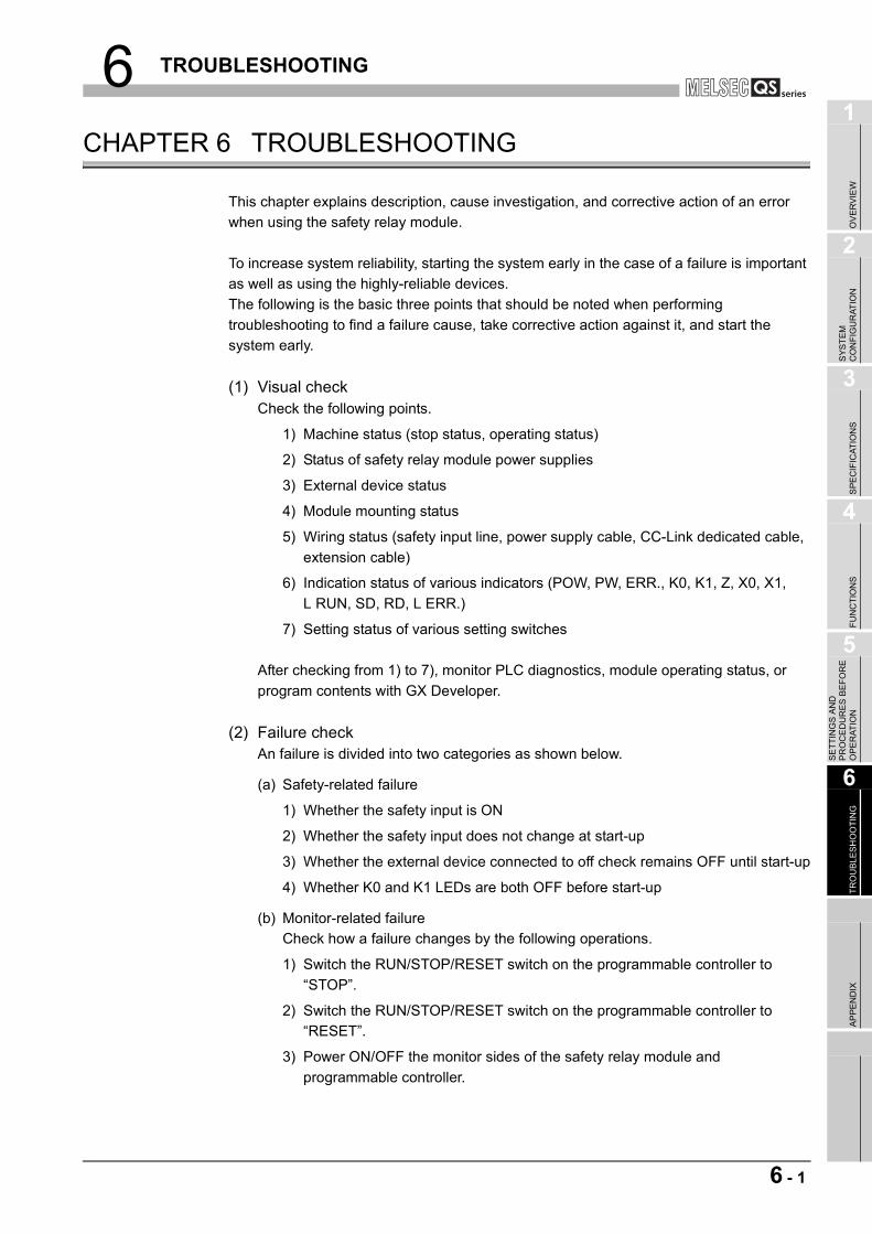
6 TROUBLESHOOTING
1
OV
ER
VIE
W
2
SY
ST
EM
C
ON
FIG
UR
AT
ION
3
SP
EC
IFIC
AT
ION
S
4
FU
NC
TIO
NS
5
SE
TT
ING
S A
ND
P
RO
CE
DU
RE
S B
EF
OR
E
OP
ER
AT
ION
6
TR
OU
BL
ES
HO
OT
ING
AP
PE
ND
IX
CHAPTER 6 TROUBLESHOOTING
This chapter explains description, cause investigation, and corrective action of an error
when using the safety relay module.
To increase system reliability, starting the system early in the case of a failure is important
as well as using the highly-reliable devices.
The following is the basic three points that should be noted when performing
troubleshooting to find a failure cause, take corrective action against it, and start the
system early.
(1) Visual checkCheck the following points.
1) Machine status (stop status, operating status)
2) Status of safety relay module power supplies
3) External device status
4) Module mounting status
5) Wiring status (safety input line, power supply cable, CC-Link dedicated cable,
extension cable)
6) Indication status of various indicators (POW, PW, ERR., K0, K1, Z, X0, X1,
L RUN, SD, RD, L ERR.)
7) Setting status of various setting switches
After checking from 1) to 7), monitor PLC diagnostics, module operating status, or
program contents with GX Developer.
(2) Failure checkAn failure is divided into two categories as shown below.
(a) Safety-related failure
1) Whether the safety input is ON
2) Whether the safety input does not change at start-up
3) Whether the external device connected to off check remains OFF until start-up
4) Whether K0 and K1 LEDs are both OFF before start-up
(b) Monitor-related failure
Check how a failure changes by the following operations.
1) Switch the RUN/STOP/RESET switch on the programmable controller to
“STOP”.
2) Switch the RUN/STOP/RESET switch on the programmable controller to
“RESET”.
3) Power ON/OFF the monitor sides of the safety relay module and
programmable controller.
6 - 1

6 TROUBLESHOOTING
(3) Narrowing down the trouble causeGuess the failure location to any of the following by checking (1) and (2) above.
1) Safety relay module or external device?
2) Main module, extension module or another module?
3) Programmable controller?
4) Sequence program?
6.1 Q Series Safety Relay Module
6.1.1 Error check method with LED
Table 6.1 shows description, cause investigation, and corrective action of errors
depending on LED display on the module.
: ON, : Flash, : OFF, *: ON or OFF
* 1: The status that start-up processing has been performed to the module
Table 6.1 Error handling of safety part with LED
LED signal Cause Corrective action
PW S PW ERR. Z K1 K0 X1 X0
Normal (before start-up) -
Normal (started up) -
* * * * * *The safety power supply is not
normally supplied.
•Check if the power supply is
normally supplied.
•Check between the power supplies
for short.
•In case of input N type, check
between the dual inputs for short.
* * *The module power supply is not
normally supplied.
•Check if the power supply is
normally supplied.
•Check between the power supplies
for short.
* * Contact welding of K0 and K1 relays
•Replace the module.
K0 and K1 relays do not turn ON.*1
* * Safety system 1 does not turn ON.*1
* * Safety system 2 does not turn ON.*1
Safety system 1 does not turn
OFF.*1
Safety system 2 does not turn
OFF.*1
* * * * * * * •System error occurred.•Check if the power supply is
normally supplied.
6 - 2 6.1 Q Series Safety Relay Module6.1.1 Error check method with LED

6 TROUBLESHOOTING
1
OV
ER
VIE
W
2
SY
ST
EM
C
ON
FIG
UR
AT
ION
3
SP
EC
IFIC
AT
ION
S
4
FU
NC
TIO
NS
5
SE
TT
ING
S A
ND
P
RO
CE
DU
RE
S B
EF
OR
E
OP
ER
AT
ION
6
TR
OU
BL
ES
HO
OT
ING
AP
PE
ND
IX
6.1.2 Error check method with monitor signal
Table 6.2 shows description, cause investigation, and corrective action of errors
depending on monitor signal.
: ON, : OFF, *: ON or OFF
POINT
If the safety power supply has not been powered ON, monitor signals that indicate
normal module operation are not displayed. (The fixed pattern shown in Table 6.2
is displayed.)
Check errors with monitor signals after powering ON the safety power supply.
Table 6.2 Error handling of safety part with monitor signal
I/O port
Cause Corrective actionX7 X6 X5 X4 X3 X2 X1 X0
Monitor signal K1RB K0RB K1 K0 XS Z X1 X0
* * * * Normal (before start-up) -
* Normal (started up) -
* * * Contact welding of K0 relay
•Replace the module.
* * * Contact welding of K1 relay
* * * Contact welding of K0 and K1 relays
*K0 relay does not turn ON.
(Due to a failure on the coil side)
*K1 relay does not turn ON.
(Due to a failure on the coil side)
*K0 and K1 relays do not turn ON.
(Due to a failure on the coil side)
* *At auto mode
Off check does not turn ON.
•Check if the wiring between start-
up inputs are normal.
•Check if the normally closed
contact connected to the off check
operates normally and the wiring is
normal.
•Check if setting of the start-up
mode is correct.
* *At manual mode
Off check does not turn OFF.
•Check if the wiring between start-
up inputs are normal.
•Check if the connected start-up
switch operates normally and the
wiring is normal.
•Check if setting of the start-up
mode is correct.
Safety system 1 does not turn ON.
•Replace the module.Safety system 2 does not turn ON.
Safety system 1 does not turn OFF.
Safety system 2 does not turn OFF.
*The safety input is incorrect.
•Check if the input device connected
to the safety input operates
normally and the wiring is normal.*
The safety power supply has not
been powered ON.Power ON the safety power supply.
6.1 Q Series Safety Relay Module6.1.2 Error check method with monitor signal
6 - 3

6 TROUBLESHOOTING
6.2 CC-Link Safety Relay Module
6.2.1 Error check method with LED
Table 6.3 shows description, cause investigation, and corrective action of errors
depending on LED display on the module.
: ON, : Flash, : OFF, *: ON or OFF
* 1: The status that start-up processing has been performed to the module
POINT
When L ERR. LED turns ON or is flashing, it indicates that an error occurred in the
CC-Link system.
For troubleshooting of the CC-Link system, refer to the following manual.
CC-Link System Compact Type Remote I/O Module User's Manual
Table 6.3 Error handling of safety part with LED
LED signal Cause Corrective action
PW S PW ERR. Z K1 K0 X1 X0
Normal (before start-up) -
Normal (started up) -
* * * * * *The safety power supply is not
normally supplied.
•Check if the power supply is
normally supplied.
•Check between the power supplies
for short.
•In case of input N type, check
between the dual inputs for short.
* * *The module power supply is not
normally supplied.
•Check if the power supply is
normally supplied.
•Check between the power supplies
for short.
* * Contact welding of K0 and K1 relays•Replace the module.
K0 and K1 relays do not turn ON.*1
Contact welding of K0 and K1 relays
•Replace the module.
K0 and K1 relays do not turn ON.*1
Safety system 1 does not turn
OFF.*1
Safety system 2 does not turn
OFF.*1
* * * * * * *
•System error occurred.
•No power supply on safety side
•Extension module communication
has not established.
•Extension module is disconnected.
•Check if the power supply is
normally supplied.
•Check between the power supplies
for short.
•Check if the extension module is
normally connected.
6 - 4 6.2 CC-Link Safety Relay Module6.2.1 Error check method with LED
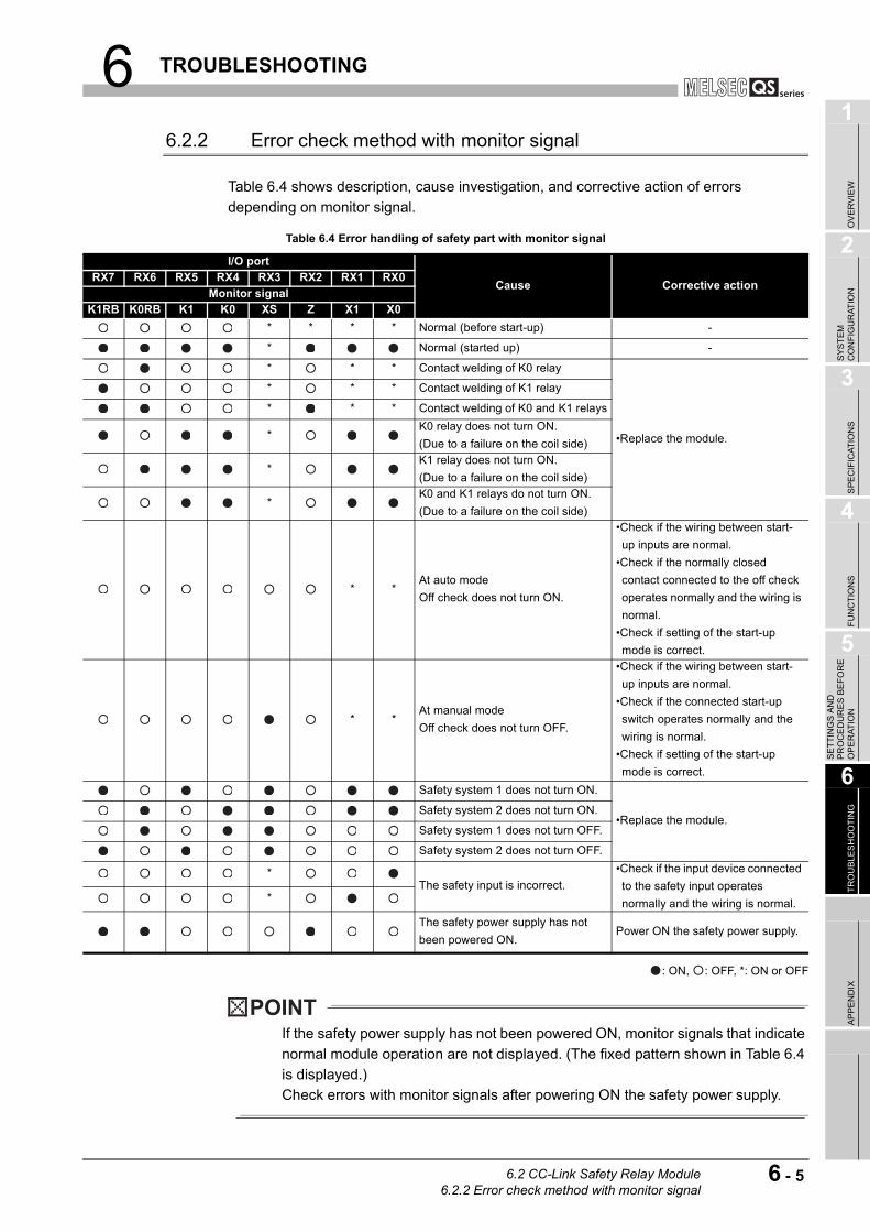
6 TROUBLESHOOTING
1
OV
ER
VIE
W
2
SY
ST
EM
C
ON
FIG
UR
AT
ION
3
SP
EC
IFIC
AT
ION
S
4
FU
NC
TIO
NS
5
SE
TT
ING
S A
ND
P
RO
CE
DU
RE
S B
EF
OR
E
OP
ER
AT
ION
6
TR
OU
BL
ES
HO
OT
ING
AP
PE
ND
IX
6.2.2 Error check method with monitor signal
Table 6.4 shows description, cause investigation, and corrective action of errors
depending on monitor signal.
: ON, : OFF, *: ON or OFF
POINT
If the safety power supply has not been powered ON, monitor signals that indicate
normal module operation are not displayed. (The fixed pattern shown in Table 6.4
is displayed.)
Check errors with monitor signals after powering ON the safety power supply.
Table 6.4 Error handling of safety part with monitor signal
I/O port
Cause Corrective actionRX7 RX6 RX5 RX4 RX3 RX2 RX1 RX0
Monitor signalK1RB K0RB K1 K0 XS Z X1 X0
* * * * Normal (before start-up) -
* Normal (started up) -
* * * Contact welding of K0 relay
•Replace the module.
* * * Contact welding of K1 relay
* * * Contact welding of K0 and K1 relays
*K0 relay does not turn ON.
(Due to a failure on the coil side)
*K1 relay does not turn ON.
(Due to a failure on the coil side)
*K0 and K1 relays do not turn ON.
(Due to a failure on the coil side)
* *At auto mode
Off check does not turn ON.
•Check if the wiring between start-
up inputs are normal.
•Check if the normally closed
contact connected to the off check
operates normally and the wiring is
normal.
•Check if setting of the start-up
mode is correct.
* *At manual mode
Off check does not turn OFF.
•Check if the wiring between start-
up inputs are normal.
•Check if the connected start-up
switch operates normally and the
wiring is normal.
•Check if setting of the start-up
mode is correct.
Safety system 1 does not turn ON.
•Replace the module.Safety system 2 does not turn ON.
Safety system 1 does not turn OFF.
Safety system 2 does not turn OFF.
*The safety input is incorrect.
•Check if the input device connected
to the safety input operates
normally and the wiring is normal.*
The safety power supply has not
been powered ON.Power ON the safety power supply.
6.2 CC-Link Safety Relay Module6.2.2 Error check method with monitor signal
6 - 5
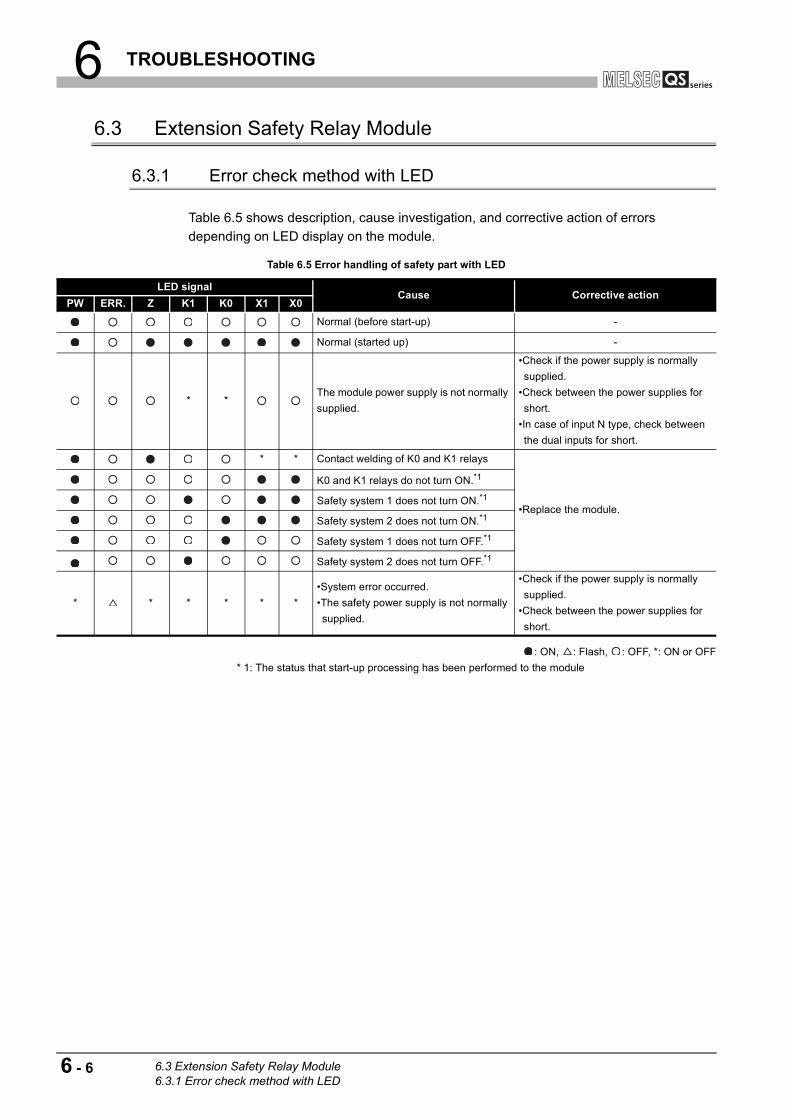
6 TROUBLESHOOTING
6.3 Extension Safety Relay Module
6.3.1 Error check method with LED
Table 6.5 shows description, cause investigation, and corrective action of errors
depending on LED display on the module.
: ON, : Flash, : OFF, *: ON or OFF
* 1: The status that start-up processing has been performed to the module
Table 6.5 Error handling of safety part with LED
LED signal Cause Corrective action
PW ERR. Z K1 K0 X1 X0
Normal (before start-up) -
Normal (started up) -
* *The module power supply is not normally
supplied.
•Check if the power supply is normally
supplied.
•Check between the power supplies for
short.
•In case of input N type, check between
the dual inputs for short.
* * Contact welding of K0 and K1 relays
•Replace the module.
K0 and K1 relays do not turn ON.*1
Safety system 1 does not turn ON.*1
Safety system 2 does not turn ON.*1
Safety system 1 does not turn OFF.*1
Safety system 2 does not turn OFF.*1
* * * * * *
•System error occurred.
•The safety power supply is not normally
supplied.
•Check if the power supply is normally
supplied.
•Check between the power supplies for
short.
6 - 6 6.3 Extension Safety Relay Module6.3.1 Error check method with LED

6 TROUBLESHOOTING
1
OV
ER
VIE
W
2
SY
ST
EM
C
ON
FIG
UR
AT
ION
3
SP
EC
IFIC
AT
ION
S
4
FU
NC
TIO
NS
5
SE
TT
ING
S A
ND
P
RO
CE
DU
RE
S B
EF
OR
E
OP
ER
AT
ION
6
TR
OU
BL
ES
HO
OT
ING
AP
PE
ND
IX
6.3.2 Error check method with monitor signal
Table 6.6 shows description, cause investigation, and corrective action of errors
depending on monitor signal.
: ON, : OFF, *: ON or OFF
POINT
If the safety power supply has not been powered ON, monitor signals that indicate
normal module operation are not displayed. (The fixed pattern shown in Table 6.6
is displayed.)
Check errors with monitor signals after powering ON the safety power supply.
If the same station number is set for the extension module, monitor signals are not
displayed properly.
Table 6.6 Error handling of safety part with monitor signal
I/O port
Cause Corrective action
X7 X6 X5 X4 X3 X2 X1 X0Monitor signal
K1R
B
K0R
BK1 K0 XS Z X1 X0
* * * Normal (before start-up) -
* Normal (started up) -
* * * Contact welding of K0 relay
•Replace the module.
* * * Contact welding of K1 relay
* * * Contact welding of K0 and K1 relays
*K0 relay does not turn ON.
(Due to a failure on the coil side)
*K1 relay does not turn ON.
(Due to a failure on the coil side)
*K0 and K1 relays do not turn ON.
(Due to a failure on the coil side)
* *At auto mode
Off check does not turn ON.
•Check if the wiring between start-up inputs are
normal.
•Check if the normally closed contact connected
to the off check operates normally and the wiring
is normal.
•Check if setting of the start-up mode is correct.
* *At manual mode
Off check does not turn OFF.
•Check if the wiring between start-up inputs are
normal.
•Check if the connected start-up switch operates
normally and the wiring is normal.
•Check if setting of the start-up mode is correct.
Safety system 1 does not turn ON.
•Replace the module.Safety system 2 does not turn ON.
Safety system 1 does not turn OFF.
Safety system 2 does not turn OFF.
*The safety input is incorrect.
•Check if the input device connected to the safety
input operates normally and the wiring is normal.*
The safety power supply has not
been powered ON.Power ON the safety power supply.
6.3 Extension Safety Relay Module6.3.2 Error check method with monitor signal
6 - 7

APPENDIX
APPENDIX
Appendix 1 External Dimensions
Appendix 1.1 Q series safety relay module
(1) QS90SR2SP-Q, QS90SR2SN-Q
Unit: mmFigure App.1 QS90SR2SP-Q, QS90SR2SN-Q
55.217.590
98
App - 1 Appendix 1 External DimensionsAppendix 1.1 Q series safety relay module

APPENDIX
1
OV
ER
VIE
W
2
SY
ST
EM
C
ON
FIG
UR
AT
ION
3
SP
EC
IFIC
AT
ION
S
4
FU
NC
TIO
NS
5
SE
TT
ING
S A
ND
P
RO
CE
DU
RE
S B
EF
OR
E
OP
ER
AT
ION
6
TR
OU
BL
ES
HO
OT
ING
AP
PE
ND
IX
Appendix 1.2 CC-Link safety relay module
(1) QS90SR2SP-CC, QS90SR2SN-CC
Unit: mmFigure App.2 QS90SR2SP-CC, QS90SR2SN-CC
113.5
6.511
2 2.4 45
Center of DIN rail
Appendix 1 External DimensionsAppendix 1.2 CC-Link safety relay module
App - 2
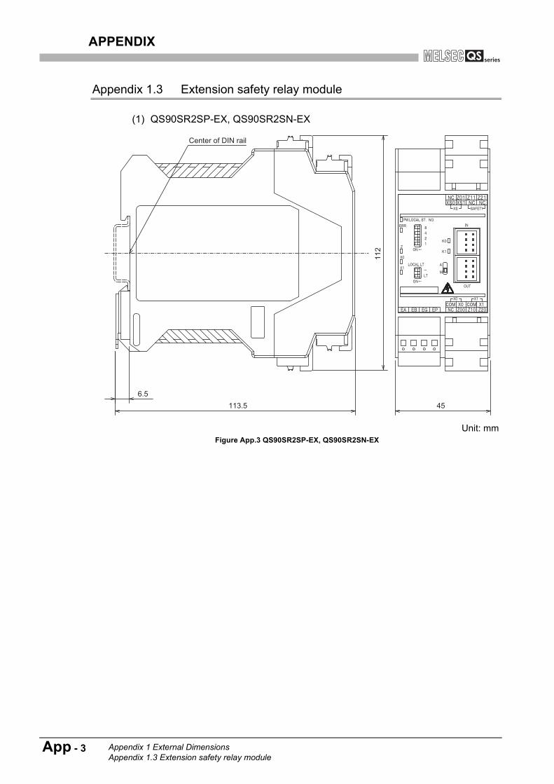
APPENDIX
Appendix 1.3 Extension safety relay module
(1) QS90SR2SP-EX, QS90SR2SN-EX
Unit: mmFigure App.3 QS90SR2SP-EX, QS90SR2SN-EX
113.56.5
112
45
Center of DIN rail
App - 3 Appendix 1 External DimensionsAppendix 1.3 Extension safety relay module

APPENDIX
1
OV
ER
VIE
W
2
SY
ST
EM
C
ON
FIG
UR
AT
ION
3
SP
EC
IFIC
AT
ION
S
4
FU
NC
TIO
NS
5
SE
TT
ING
S A
ND
P
RO
CE
DU
RE
S B
EF
OR
E
OP
ER
AT
ION
6
TR
OU
BL
ES
HO
OT
ING
AP
PE
ND
IX
Memo
Appendix 1 External DimensionsAppendix 1.3 Extension safety relay module
App - 4
WARRANTYPlease confirm the following product warranty details before using this product.
1. Limited Warranty and Product Support.a. Mitsubishi Electric Company ("MELCO") warrants that for a period of eighteen (18) months after date of delivery from the point
of manufacture or one year from date of Customer's purchase, whichever is less, Mitsubishi Safety relay module (the"Products") will be free from defects in material and workmanship.
b. At MELCO's option, for those Products MELCO determines are not as warranted, MELCO shall either repair or replace them orissue a credit or return the purchase price paid for them.
c. For this warranty to apply:(1) Customer shall give MELCO (i) notice of a warranty claim to MELCO and the authorized dealer or distributor from whom the
Products were purchased, (ii) the notice shall describe in reasonable details the warranty problem, (iii) the notice shall beprovided promptly and in no event later than thirty (30) days after the Customer knows or has reason to believe thatProducts are not as warranted, and (iv) in any event, the notice must given within the warranty period;
(2) Customer shall cooperate with MELCO and MELCO's representatives in MELCO's investigation of the warranty claim,including preserving evidence of the claim and its causes, meaningfully responding to MELCO's questions and investigationof the problem, grant MELCO access to witnesses, personnel, documents, physical evidence and records concerning thewarranty problem, and allow MELCO to examine and test the Products in question offsite or at the premises where they areinstalled or used; and
(3) If MELCO requests, Customer shall remove Products it claims are defective and ship them to MELCO or MELCO'sauthorized representative for examination and, if found defective, for repair or replacement. The costs of removal, shipmentto and from MELCO's designated examination point, and reinstallation of repaired or replaced Products shall be atCustomer's expense.
(4) If Customer requests and MELCO agrees to effect repairs onsite at any domestic or overseas location, the Customer willpay for the costs of sending repair personnel and shipping parts. MELCO is not responsible for any re-commissioning,maintenance, or testing on-site that involves repairs or replacing of the Products.
d. Repairs of Products located outside of Japan are accepted by MELCO's local authorized service facility centers ("FA Centers").Terms and conditions on which each FA Center offers repair services for Products that are out of warranty or not covered byMELCO's limited warranty may vary.
e. Subject to availability of spare parts, MELCO will offer Product repair services for (7) years after each Product model or line isdiscontinued, at MELCO's or its FA Centers' rates and charges and standard terms in effect at the time of repair. MELCOusually produces and retains sufficient spare parts for repairs of its Products for a period of seven (7) years after production isdiscontinued.
f. MELCO generally announces discontinuation of Products through MELCO's Technical Bulletins. Products discontinued andrepair parts for them may not be available after their production is discontinued.
2. Limits of Warranties.a. MELCO does not warrant or guarantee the design, specify, manufacture, construction or installation of the materials,
construction criteria, functionality, use, properties or other characteristics of the equipment, systems, or production lines intowhich the Products may be incorporated, including any safety, fail-safe and shut down systems using the Products.
b. MELCO is not responsible for determining the suitability of the Products for their intended purpose and use, includingdetermining if the Products provide appropriate safety margins and redundancies for the applications, equipment or systemsinto which they are incorporated.
c. Customer acknowledges that qualified and experienced personnel are required to determine the suitability, application, design,construction and proper installation and integration of the Products. MELCO does not supply such personnel.
d. MELCO is not responsible for designing and conducting tests to determine that the Product functions appropriately and meetsapplication standards and requirements as installed or incorporated into the end-user's equipment, production lines or systems.
e. MELCO does not warrant any Product:(1) repaired or altered by persons other than MELCO or its authorized engineers or FA Centers;(2) subjected to negligence, carelessness, accident, misuse, or damage;(3) improperly stored, handled, installed or maintained; (4) integrated or used in connection with improperly designed, incompatible or defective hardware or software;(5) that fails because consumable parts such as relay, batteries, backlights, or fuses were not tested, serviced or replaced;(6) operated or used with equipment, production lines or systems that do not meet applicable and commensurate legal, safety
and industry-accepted standards;(7) operated or used in abnormal applications;(8) installed, operated or used in contravention of instructions, precautions or warnings contained in MELCO's user, instruction
and/or safety manuals, technical bulletins and guidelines for the Products;(9) used with obsolete technologies or technologies not fully tested and widely accepted and in use at the time of the Product's
manufacture;(10) subjected to excessive heat or moisture, abnormal voltages, shock, excessive vibration, physical damage or other
improper environment; or(11) damaged or malfunctioning due to Acts of God, fires, acts of vandals, criminals or terrorists, communication or power
failures, or any other cause or failure that results from circumstances beyond MELCO's control.f. All Product information and specifications contained on MELCO's website and in catalogs, manuals, or technical information
materials provided by MELCO are subject to change without prior notice.

g. The Product information and statements contained on MELCO's website and in catalogs, manuals, technical bulletins or othermaterials provided by MELCO are provided as a guide for Customer's use. They do not constitute warranties and are notincorporated in the contract of sale for the Products.
h. These terms and conditions constitute the entire agreement between Customer and MELCO with respect to warranties,remedies and damages and supersede any other understandings, whether written or oral, between the parties. Customerexpressly acknowledges that any representations or statements made by MELCO or others concerning the Products outsidethese terms are not part of the basis of the bargain between the parties and are not factored into the pricing of the Products.
i. THE WARRANTIES AND REMEDIES SET FORTH IN THESE TERMS ARE THE EXCLUSIVE AND ONLY WARRANTIESAND REMEDIES THAT APPLY TO THE PRODUCTS.
j. MELCO DISCLAIMS THE IMPLIED WARRANTIES OF MERCHANTABILITY AND FITNESS FOR A PARTICULAR PURPOSE.
3. Limits on Damages.a. MELCO'S MAXIMUM CUMULATIVE LIABILITY BASED ON ANY CLAIMS FOR BREACH OF WARRANTY OR CONTRACT,
NEGLIGENCE, STRICT TORT LIABILITY OR OTHER THEORIES OF RECOVERY REGARDING THE SALE, REPAIR,REPLACEMENT, DELIVERY, PERFORMANCE, CONDITION, SUITABILITY, COMPLIANCE, OR OTHER ASPECTS OF THEPRODUCTS OR THEIR SALE, INSTALLATION OR USE SHALL BE LIMITED TO THE PRICE PAID FOR PRODUCTS NOT ASWARRANTED.
b. Although MELCO has obtained the certification for Product's compliance to the international safety standard ISO13849-1 fromTUV SUD, this fact does not guarantee that Product will be free from any malfunction or failure. The user of this Product shallcomply with any and all applicable safety standard, regulation or law and take appropriate safety measures for the system inwhich the Product is installed or used and shall take the second or third safety measures other than the Product. MELCO is notliable for damages that could have been prevented by compliance with any applicable safety standard, regulation or law.
c. MELCO prohibits the use of Products with or in any application involving power plants, trains, railway systems, airplanes, airlineoperations, other transportation systems, amusement equipments, hospitals, medical care, dialysis and life support facilities orequipment, incineration and fuel devices, handling of nuclear or hazardous materials or chemicals, mining and drilling, andother applications where the level of risk to human life, health or property are elevated.
d. MELCO SHALL NOT BE LIABLE FOR SPECIAL, INCIDENTAL, CONSEQUENTIAL, INDIRECT OR PUNITIVE DAMAGES,FOR LOSS OF PROFITS, SALES, OR REVENUE, FOR INCREASED LABOR OR OVERHEAD COSTS, FOR DOWNTIME ORLOSS OF PRODUCTION, FOR COST OVERRUNS, OR FOR ENVIRONMENTAL OR POLLUTION DAMAGES OR CLEAN-UPCOSTS, WHETHER THE LOSS IS BASED ON CLAIMS FOR BREACH OF CONTRACT OR WARRANTY, VIOLATION OFSTATUTE, NEGLIGENCE OR OTHER TORT, STRICT LIABILITY OR OTHERWISE.
e. In the event that any damages which are asserted against MELCO arising out of or relating to the Products or defects in them,consist of personal injury, wrongful death and/or physical property damages as well as damages of a pecuniary nature, thedisclaimers and limitations contained in these terms shall apply to all three types of damages to the fullest extent permitted bylaw. If, however, the personal injury, wrongful death and/or physical property damages cannot be disclaimed or limited by law orpublic policy to the extent provided by these terms, then in any such event the disclaimer of and limitations on pecuniary oreconomic consequential and incidental damages shall nevertheless be enforceable to the fullest extent allowed by law.
f. In no event shall any cause of action arising out of breach of warranty or otherwise concerning the Products be brought byCustomer more than one year after the cause of action accrues.
g. Each of the limitations on remedies and damages set forth in these terms is separate and independently enforceable,notwithstanding the unenforceability or failure of essential purpose of any warranty, undertaking, damage limitation, otherprovision of these terms or other terms comprising the contract of sale between Customer and MELCO.
4. Delivery/Force Majeure.a. Any delivery date for the Products acknowledged by MELCO is an estimated and not a promised date. MELCO will make all
reasonable efforts to meet the delivery schedule set forth in Customer's order or the purchase contract but shall not be liable forfailure to do so.
b. Products stored at the request of Customer or because Customer refuses or delays shipment shall be at the risk and expenseof Customer.
c. MELCO shall not be liable for any damage to or loss of the Products or any delay in or failure to deliver, service, repair orreplace the Products arising from shortage of raw materials, failure of suppliers to make timely delivery, labor difficulties of anykind, earthquake, fire, windstorm, flood, theft, criminal or terrorist acts, war, embargoes, governmental acts or rulings, loss ordamage or delays in carriage, acts of God, vandals or any other circumstances reasonably beyond MELCO's control.
5. Choice of Law/Jurisdiction.These terms and any agreement or contract between Customer and MELCO shall be governed by the laws of the State of NewYork without regard to conflicts of laws. To the extent any action or dispute is not arbitrated, the parties consent to the exclusivejurisdiction and venue of the federal and state courts located in the Southern District of the State of New York. Any judgment thereobtained may be enforced in any court of competent jurisdiction.
6. Arbitration.Any controversy or claim arising out of, or relating to or in connection with the Products, their sale or use or these terms, shall besettled by arbitration conducted in accordance with the Center for Public Resources (CPR) Rules for Non-Administered Arbitrationof International Disputes, by a sole arbitrator chosen from the CPR's panels of distinguished neutrals. Judgment upon the awardrendered by the Arbitrator shall be final and binding and may be entered by any court having jurisdiction thereof. The place of thearbitration shall be New York City, New York. The language of the arbitration shall be English. The neutral organization designatedto perform the functions specified in Rule 6 and Rules 7.7(b), 7.8 and 7.9 shall be the CPR.

The company names, system names and product names mentioned in this manual are either registered trademarks or
trademarks of their respective companies.
In some cases, trademark symbols such as '™' or '®' are not specified in this manual.
SH(NA)-080746ENG-F


SH(NA)-080746ENG-F(1612)MEE
MODEL: QS-SR-U-SY-E
MODEL CODE: 13JY62
Specifications subject to change without notice.
When exported from Japan, this manual does not require application to theMinistry of Economy, Trade and Industry for service transaction permission.
HEAD OFFICE : TOKYO BUILDING, 2-7-3 MARUNOUCHI, CHIYODA-KU, TOKYO 100-8310, JAPANNAGOYA WORKS : 1-14 , YADA-MINAMI 5-CHOME , HIGASHI-KU, NAGOYA , JAPAN