Embed Size (px)
Citation preview
Standing between workers and hazards
.
Mitsubishi Safety Programmable Controller/Safety Relay ModuleMELSEC Safety
Hazardous Zone
Machine Trouble
Human Risk
System Down
System Hazard
Hazardous Zone
Machine Trouble
Human Risk
System Down
System Hazard
Hazardous Zone
Machine Trouble
Human Risk
System Down
System Hazard
2 3
As many industries have expanded globally, it has become necessary to conform to international standards
such as ISO12100 (JIS B 9700) "Safety of machinery - basic concepts, general principles for design"
in order to ensure workplace safety. At the same time, the safety concept has shifted from
human intervention based "zero accidents" to risk assessment based "zero risk".
As a solution for this, Mitsubishi Electric has introduced the MELSEC-QS Safety programmable controller,
based on the world leading technology of the established Q Series Automation Platform.
This solution conforms to international safety standards and maintains compatibility with
other MELSEC programmable controllers while providing a comprehensive safety control solution.
The concept of safetyis shifting from
"zero accidents" to "zero risk."
P4
P6
P8
P10
P11
P16
P20
P26
P27
P29
P30
Safety Standards
Safety Solutions
P32
P34
P35
Partners
Warranty
Related Catalogs
Safety Programmable Controller
New Functions
Features
Application Examples
Specifications & External Dimensions
Safety Relay Module
Features
Application Examples
Specifications & External Dimensions
Safety Programm
able ControllerS
afety Relay M
odule
"Safety" is crucial on the shop floor.
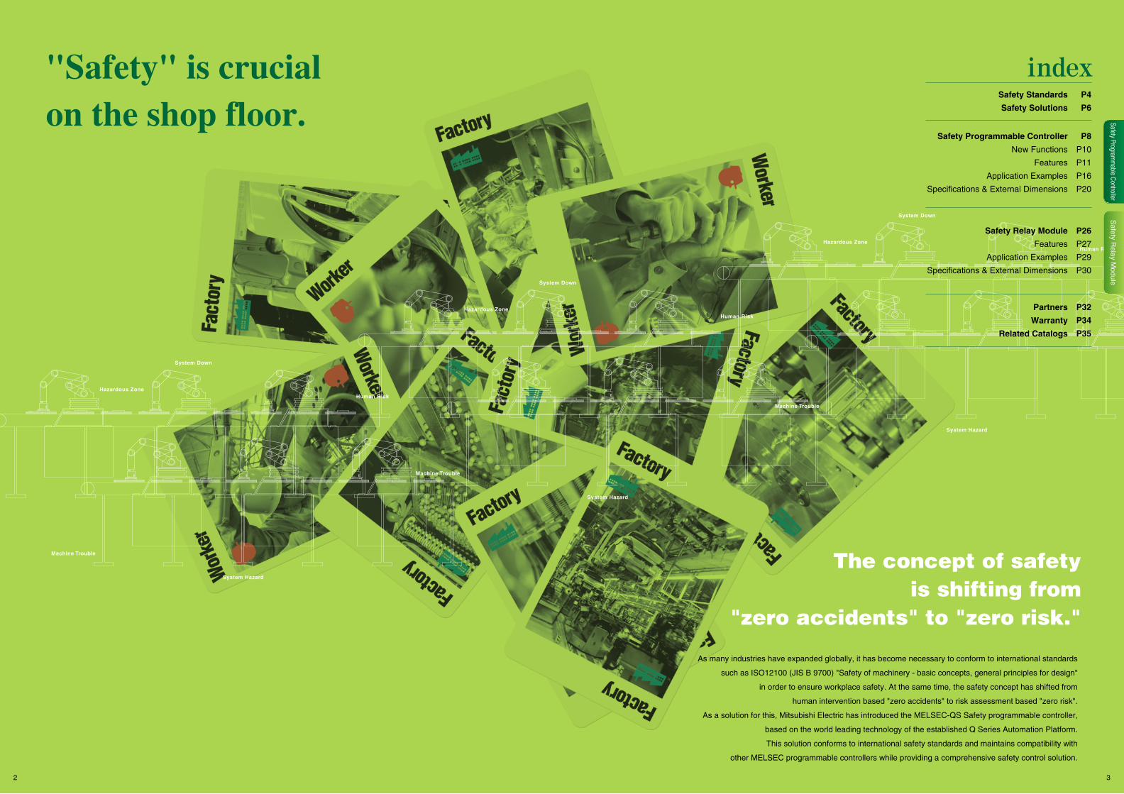
ISO13849-1:2006 Performance level
Functional safety standard IEC61508
1
S1
F1P1
PLr
a
b
c
d
e
P2
P1
P2
P1
P2
P1
P2
F2
F1
F2
S2
Risk chart in ISO13849-1:2006 and PLr for safety function
H
S
Severity of injury
F
Frequency or duration of exposure to risk
P
Possibility of avoiding or deterring risk
S1
Minor injury
F1
Rarely to low frequency or for a brief period
P1
Possible under certain conditions
S2
Serious injury
F2
Frequently to continuously or for a long period
P2
Almost impossible
International safety standards
L
Ensuring safety in manufacturing facilities around the world, while meeting growing demands for compliance with international standards.
"Risk assessment" refers to identifying potential hazards present in machinery and evaluating the degree of hazard (risk).
(Risk assessment procedure)
ISO14121 (JIS B 9702) Risk assessment
Risk analysis
Risk assessment
Risk reduction
Inherently safe design
Safety protection by system STOP
Safety protection by risk isolation
Safety fence
Safety device (1)
Safety device (2)
Safety fence
Emergency stop component
Securing zero-energy condition
Risk status displays and warnings
Appended documentationand operation manuals
Safegurads
Safety measures
Additional safety measures
Information for use (residual risks)
YES
NO
ISO12100 (JIS B 9700) Risk reduction and safety measures
Identification of useand foreseeable misuse
Start
End
Hazard identification
Risk estimation
Risk evaluation
Was tolerable risk attained?
International standards for machinery safety are hierarchically classified into the following types: Type A standards (basic safety standards): ISO12100 and ISO14121 Type B standards (group safety standards): ISO13849-1, IEC61508, etc. Type C standards: Individual product standards
Performance levels for safety-related parts of control systems have been revised in ISO13849-1:2006. Based on the original safety categories, frequency of a dangerous failure occurrence (the safety function does not work when needed), rate of a failure detection by diagnostics, etc. were added to evaluate comprehensively. The evaluation result is classified into five levels from "a" to "e" by the performance level (PL). The categories and the safety integrity level (SIL) described in the functional safety standard IEC61508 can be referred to each
other via the PL. Like the safety categories, the risk is evaluated from a perspective of "S: Severity of injury," "F: Frequency or duration of
exposure to risk," and "P: Possibility of avoidance."
In the past, a safety function of control systems were realized by safety relays and mechanical safety components. The safety function was standardized in the international safety standard ISO13849-1 (EN954-1) and classified by categories. But ISO13849-1 applied to only parts and components with a clear failure mode. Besides, the safety standards for electrical equipment of machines, such as IEC60204-1, stipulated that emergency stop circuits should be hard wired.In recent years, however, with progress of microprocessor technologies, widespread IT, more complex control, etc., demands for configuring safety systems using microprocessors and software have been increased. To meet such demands of the time, the functional safety concept was developed, and the functional safety standard IEC61508 (electrical/electronic/programmable electronic safety-related systems), which applies to programmable controllers, was issued in 2000.
Risk analysis
Serious injury
Minor injury(abrasion)
Avoidable
Unavoidable
Possibility of avoidance
Avoidable
Unavoidable
Possibility of avoidance
Frequency/durationof exposure to risk
Severity of injury
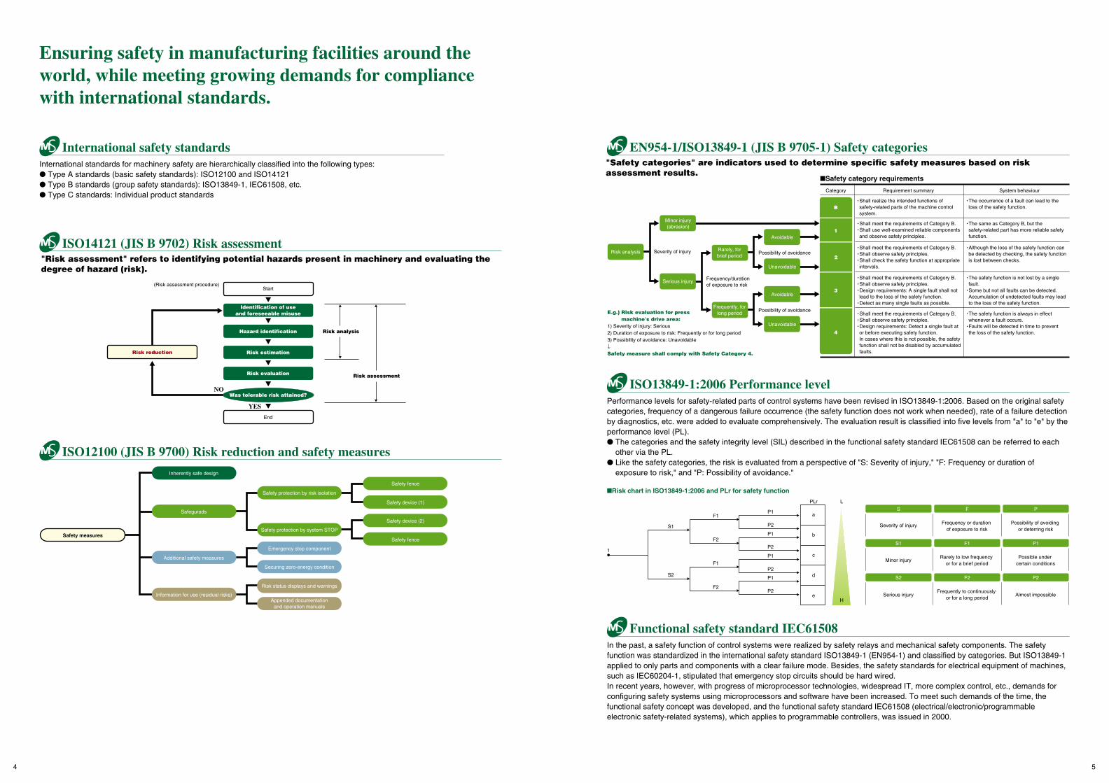
E.g.) Risk evaluation for press machine's drive area:
1) Severity of injury: Serious2) Duration of exposure to risk: Frequently or for long period3) Possibility of avoidance: Unavoidable↓Safety measure shall comply with Safety Category 4.
Category Requirement summary System behaviour
• Shall realize the intended functions of safety-related parts of the machine control system.
• Shall meet the requirements of Category B.• Shall use well-examined reliable components and observe safety principles.
• The occurrence of a fault can lead to the loss of the safety function.
• The same as Category B, but the safety-related part has more reliable safety function.
• Shall meet the requirements of Category B.• Shall observe safety principles.• Shall check the safety function at appropriateintervals.
• Although the loss of the safety function can be detected by checking, the safety function is lost between checks.
• Shall meet the requirements of Category B.• Shall observe safety principles.• Design requirements: A single fault shall not lead to the loss of the safety function.
• Detect as many single faults as possible.
• The safety function is not lost by a single fault.
• Some but not all faults can be detected. Accumulation of undetected faults may lead to the loss of the safety function.
• Shall meet the requirements of Category B.• Shall observe safety principles.• Design requirements: Detect a single fault at or before executing safety function.In cases where this is not possible, the safety function shall not be disabled by accumulated faults.
• The safety function is always in effect whenever a fault occurs.
• Faults will be detected in time to prevent the loss of the safety function.
"Safety categories" are indicators used to determine specific safety measures based on risk assessment results.
Safety category requirements
B
1
2
3
4
EN954-1/ISO13849-1 (JIS B 9705-1) Safety categories
Rarely, forbrief period
Frequently, forlong period
4 5
User applicationService user layer
Application layer
User application
Safety transmission
Structure control
Standardtransmission
Structurecontrol
Safetytransmission
CC-Link data link protocol CC-Link data link protocol
RS-485 compliant
Data link layer
Physical layer RS-485 compliant
GX Developer safety compliant engineering environment
CC-Link Safety open field network
AdministratorsDevelopersUsers
Login authentication screenUser sets the access level Functions restricted accordingto the access level
CPU access password verification
Repeated reception of old message
Missing message
Message insertion
Wrong message order
Incorrect message content
Failure to arrive at specified time
Separation of safety information andnon-safety information
The same as CC-Link:standard remote stations and
remote device stations connectable
Safety master station(Supportes CC-Link Safety)
Safety slave station(Supports CC-Link)
Communication errordetection function
GX Developer
CPU access passwordAuthorized
Rejected
CPU access password
CPU access password
"ABC123" "ABC123"
"DEF123"
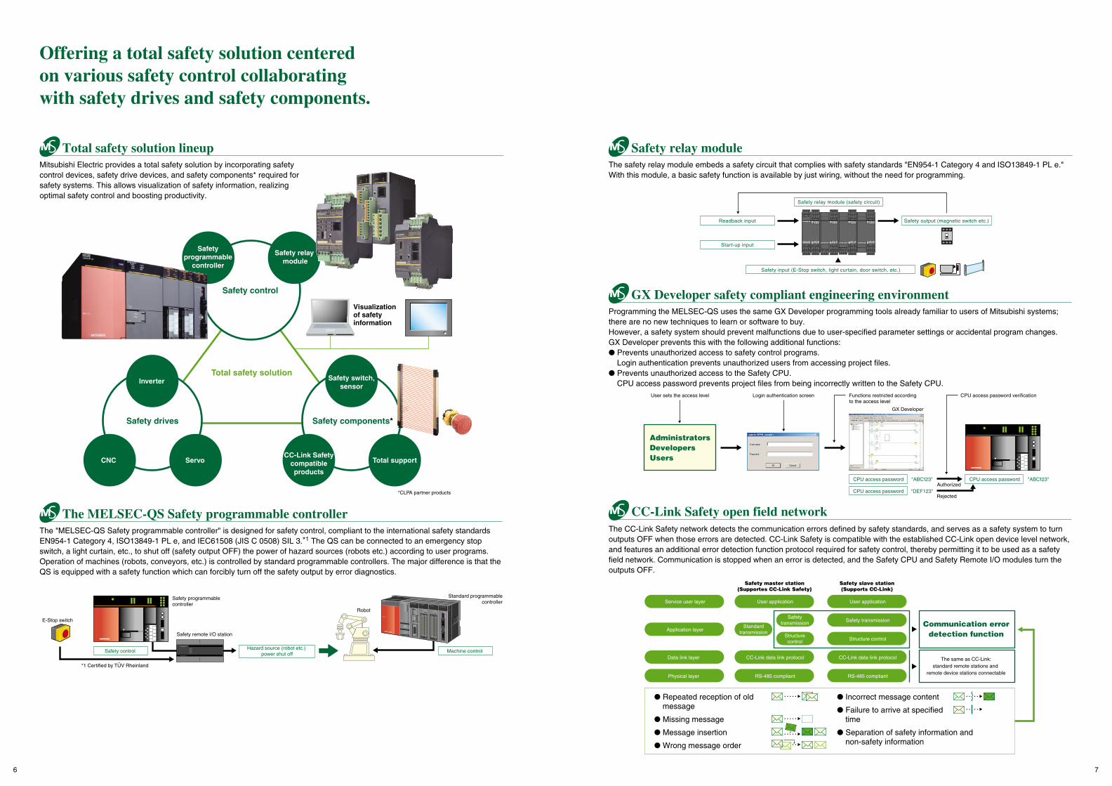
Programming the MELSEC-QS uses the same GX Developer programming tools already familiar to users of Mitsubishi systems; there are no new techniques to learn or software to buy. However, a safety system should prevent malfunctions due to user-specified parameter settings or accidental program changes. GX Developer prevents this with the following additional functions: Prevents unauthorized access to safety control programs.
Login authentication prevents unauthorized users from accessing project files. Prevents unauthorized access to the Safety CPU.
CPU access password prevents project files from being incorrectly written to the Safety CPU.
The CC-Link Safety network detects the communication errors defined by safety standards, and serves as a safety system to turn outputs OFF when those errors are detected. CC-Link Safety is compatible with the established CC-Link open device level network, and features an additional error detection function protocol required for safety control, thereby permitting it to be used as a safety field network. Communication is stopped when an error is detected, and the Safety CPU and Safety Remote I/O modules turn the outputs OFF.
Readback input Safety output (magnetic switch etc.)
Start-up input
Safety input (E-Stop switch, light curtain, door switch, etc.)
Safety relay module (safety circuit)
*CLPA partner products
Total safety solution lineup Safety relay module
Total safety solution
Safety control
Safety components*
CC-Link Safetycompatibleproducts
Total support
Safety switch,sensor
Safety drives
CNC Servo
Inverter
Visualization of safety information
Safetyprogrammable
controller
Safety relay module
Offering a total safety solution centered on various safety control collaborating with safety drives and safety components.
Mitsubishi Electric provides a total safety solution by incorporating safety control devices, safety drive devices, and safety components* required for safety systems. This allows visualization of safety information, realizing optimal safety control and boosting productivity.
QY42P
PULL
POWERQ25HCPU
USB
QY42P
PULL
MODERUNERR
USERBAT
BOOT
RS-232
QJ71LP21-25
The MELSEC-QS Safety programmable controller
Safety programmablecontroller
Standard programmablecontroller
Robot
Machine controlSafety controlHazard source (robot etc.)
power shut off
E-Stop switch
Safety remote I/O station
*1 Certified by TUV Rheinland
The "MELSEC-QS Safety programmable controller" is designed for safety control, compliant to the international safety standards EN954-1 Category 4, ISO13849-1 PL e, and IEC61508 (JIS C 0508) SIL 3.*1 The QS can be connected to an emergency stop switch, a light curtain, etc., to shut off (safety output OFF) the power of hazard sources (robots etc.) according to user programs. Operation of machines (robots, conveyors, etc.) is controlled by standard programmable controllers. The major difference is that the QS is equipped with a safety function which can forcibly turn off the safety output by error diagnostics.
The safety relay module embeds a safety circuit that complies with safety standards "EN954-1 Category 4 and ISO13849-1 PL e." With this module, a basic safety function is available by just wiring, without the need for programming.
6 7
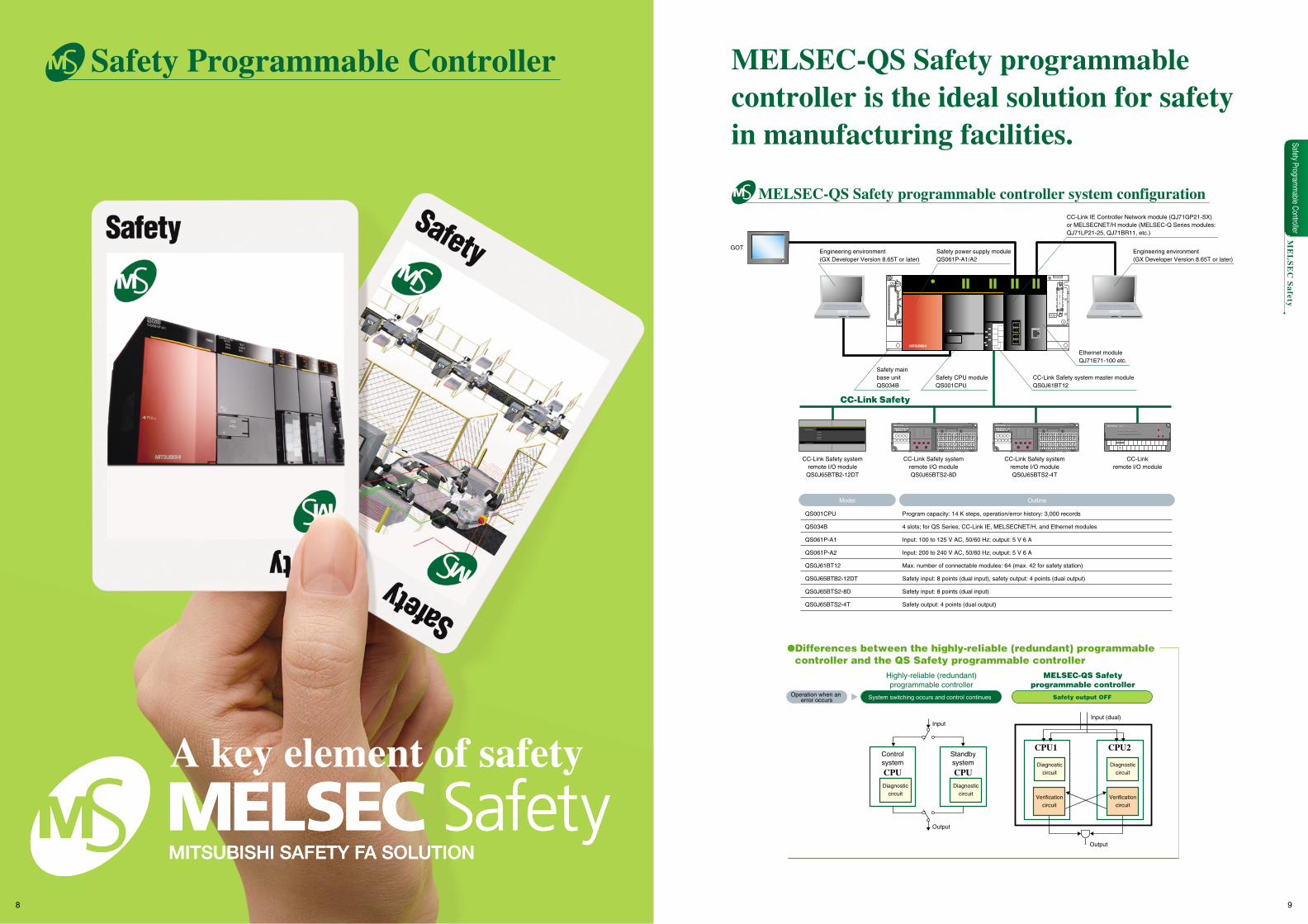
MELSEC-QS Safety programmablecontroller is the ideal solution for safety in manufacturing facilities.
Verificationcircuit
Verificationcircuit
Differences between the highly-reliable (redundant) programmable controller and the QS Safety programmable controller
Standbysystem
CPUDiagnostic
circuitDiagnostic
circuit
Diagnosticcircuit
Diagnosticcircuit
Controlsystem
CPU
Input (dual)Input
Output
Output
CPU2CPU1
Highly-reliable (redundant)programmable controller
MELSEC-QS Safetyprogrammable controller
Operation when an error occurs System switching occurs and control continues Safety output OFF
CC-Linkremote I/O module
Model
QS001CPU
QS034B
QS061P-A1
QS061P-A2
QS0J61BT12
QS0J65BTB2-12DT
QS0J65BTS2-8D
QS0J65BTS2-4T
Program capacity: 14 K steps, operation/error history: 3,000 records
4 slots; for QS Series, CC-Link IE, MELSECNET/H, and Ethernet modules
Input: 100 to 125 V AC, 50/60 Hz; output: 5 V 6 A
Input: 200 to 240 V AC, 50/60 Hz; output: 5 V 6 A
Max. number of connectable modules: 64 (max. 42 for safety station)
Safety input: 8 points (dual input), safety output: 4 points (dual output)
Safety input: 8 points (dual input)
Safety output: 4 points (dual output)
Outline
CC-Link Safety systemremote I/O module
QS0J65BTB2-12DT
Safety power supply moduleQS061P-A1/A2
Safety CPU moduleQS001CPU
CC-Link IE Controller Network module (QJ71GP21-SX) or MELSECNET/H module (MELSEC-Q Series modules: QJ71LP21-25, QJ71BR11, etc.)
CC-Link Safety system master moduleQS0J61BT12
Engineering environment(GX Developer Version 8.65T or later)
GOTEngineering environment(GX Developer Version 8.65T or later)
CC-Link Safety
MELSEC-QS Safety programmable controller system configuration
ME
LS
EC
Safety
STATION NO.X10 X1
5
0 1
46
23
5
0 1
46
9237
8
0 1
4
23
AJ65BTB1-16D
0
PW
1 2 3 4 5 6 7 8 9 A B C D E F
L RUN SD RD L ERR.
DA DG
DB SLD
(FG)
1 3 5 7 9 11 13 15 17 19 21 23 25 27
2 4 6 8 10 12 14 16 18 20 22 24 26
+24V 24G
B RATE
CC-Link Safety systemremote I/O moduleQS0J65BTS2-8D
CC-Link Safety systemremote I/O moduleQS0J65BTS2-4T
Safety main base unitQS034B
NC
NCNC Y2+ NC Y2- NC Y3+ NC Y3-Y1-NCY1+NCNC Y0-Y0+NC
COM- I/O 24GI/O 24VNC
321Y0
x1x10
SETRESET
B RATESTATION NO.
432
10987
0 123
456
0 123
456
10
6 5 4
237
ELLBT
LINK ID
RD
SD
L ERR.
L RUN
ERR.
SAFETY
RUN
POWER(FG)SLDDB
24G+24VDGDA
QS0J65BTS2-4T
NC
NCNC Y2+ NC Y2- NC Y3+ NC Y3-Y1-NCY1+NCNC Y0-Y0+NC
COM- I/O 24GI/O 24VNC
321Y0
x1x10
SETRESET
B RATESTATION NO.
432
10987
0 123
456
0 123
456
10
6 5 4
237
ELLBT
LINK ID
RD
SD
L ERR.
L RUN
ERR.
SAFETY
RUN
POWER(FG)SLDDB
24G+24VDGDA
QS0J65BTS2-4T
Ethernet moduleQJ71E71-100 etc.
A key element of safety
Safety Programm
able Controller
8 9
Safety Programmable Controller
QY42P
PULL
POWERQ25HCPU
USB
QY42P
PULL
MODERUNERR
USERBAT
BOOT
RS-232
QJ71LP21-25
NC
NCNC Y2+ NC Y2- NC Y3+ NC Y3-Y1-NCY1+NCNC Y0-Y0+NC
COM- I/O 24GI/O 24VNC
321Y0
x1x10
SETRESET
B RATESTATION NO.
432
10987
0 123
456
0 123
456
10
6 5 4
237
ELLBT
LINK ID
RD
SD
L ERR.
L RUN
ERR.
SAFETY
RUN
POWER(FG)SLDDB
24G+24VDGDA
QS0J65BTS2-4T
New Functions Solutions
Ethernet, CC-Link IE
CC-Link Safety
GOT MELSEC (standard control)
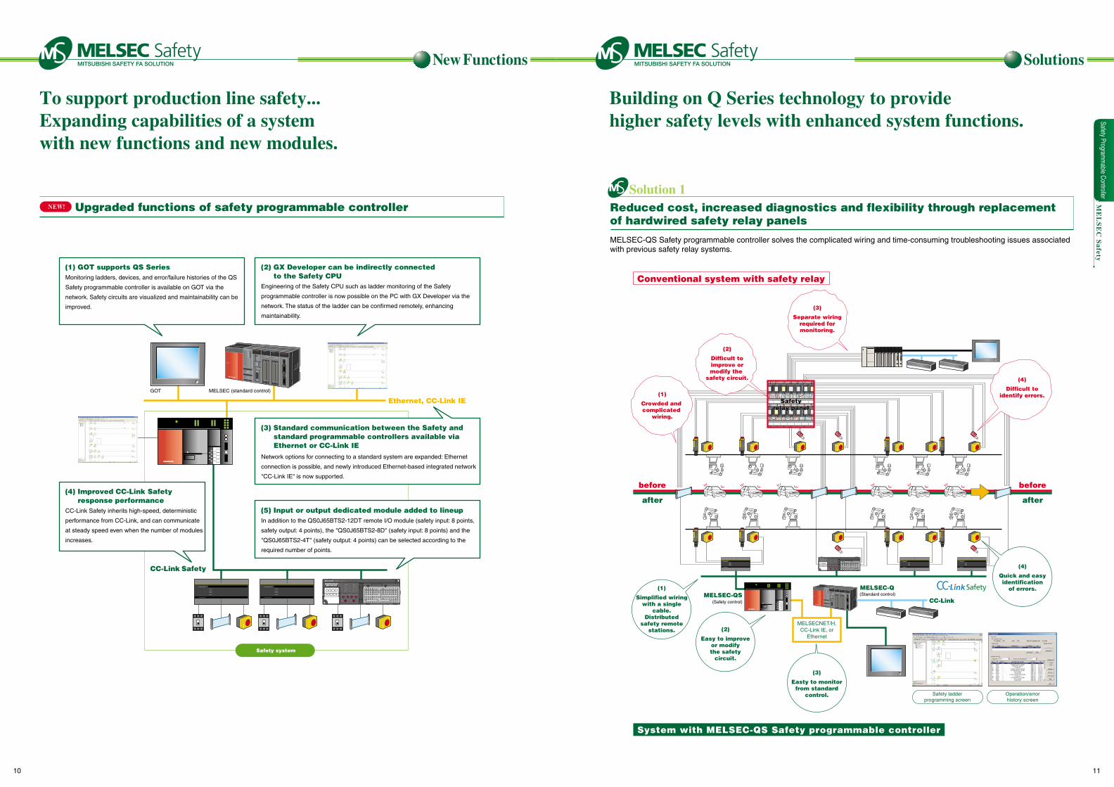
Upgraded functions of safety programmable controller
(1) GOT supports QS SeriesMonitoring ladders, devices, and error/failure histories of the QS
Safety programmable controller is available on GOT via the
network. Safety circuits are visualized and maintainability can be
improved.
(2) GX Developer can be indirectly connected to the Safety CPU
Engineering of the Safety CPU such as ladder monitoring of the Safety
programmable controller is now possible on the PC with GX Developer via the
network. The status of the ladder can be confirmed remotely, enhancing
maintainability.
Safety system
ME
LS
EC
Safety
NC
NCNC Y2+ NC Y2- NC Y3+ NC Y3-Y1-NCY1+NCNC Y0-Y0+NC
COM- I/O 24GI/O 24VNC
321Y0
x1x10
SETRESET
B RATESTATION NO.
432
10987
0 123
456
0 123
456
10
6 5 4
237
ELLBT
LINK ID
RD
SD
L ERR.
L RUN
ERR.
SAFETY
RUN
POWER(FG)SLDDB
24G+24VDGDA
QS0J65BTS2-4T
Network options for connecting to a standard system are expanded: Ethernet
connection is possible, and newly introduced Ethernet-based integrated network
"CC-Link IE" is now supported.
In addition to the QS0J65BTS2-12DT remote I/O module (safety input: 8 points,
safety output: 4 points), the "QS0J65BTS2-8D" (safety input: 8 points) and the
"QS0J65BTS2-4T" (safety output: 4 points) can be selected according to the
required number of points.
(3) Standard communication between the Safety and standard programmable controllers available via Ethernet or CC-Link IE
(5) Input or output dedicated module added to lineup
(4) Improved CC-Link Safety response performance
CC-Link Safety inherits high-speed, deterministic
performance from CC-Link, and can communicate
at steady speed even when the number of modules
increases.
To support production line safety...Expanding capabilities of a system with new functions and new modules.
before
after
before
after
AX10A4UCPUA62P AX10 AX10 AX10 AY11 AY11 AJ71BR11 AJ71BR11
QY42P
PULL
POWERQ25HCPU
USB
QY42P
PULL
MODERUNERR
USERBAT
BOOT
RS-232
QJ71LP21-25
Safetyrelay panel
Safetyrelay panel
Building on Q Series technology to provide higher safety levels with enhanced system functions.
Solution 1Reduced cost, increased diagnostics and flexibility through replacementof hardwired safety relay panels
MELSEC-QS Safety programmable controller solves the complicated wiring and time-consuming troubleshooting issues associated with previous safety relay systems.
Conventional system with safety relay
System with MELSEC-QS Safety programmable controller
(2)
Difficult toimprove ormodify the
safety circuit. (4)
Difficult toidentify errors.
(1)
Simplified wiringwith a single
cable.Distributed
safety remotestations.
(1)
Crowded and complicated
wiring.
(4)
Quick and easyidentification
of errors.
(3)
Easty to monitorfrom standard
control.
(2)
Easy to improveor modifythe safety
circuit.
(3)
Separate wiringrequired formonitoring.
MELSEC-QSMELSEC-Q
CC-Link
MELSECNET/H,CC-Link IE, or
Ethernet
(Safety control)
(Standard control)
Safety ladderprogramming screen
Operation/errorhistory screen
Safety Programm
able Controller
10 11
Solution 2
Solution 3
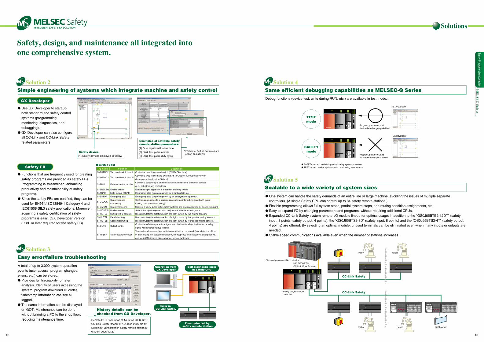
Simple engineering of systems which integrate machine and safety control
Easy error/failure troubleshooting
Error detected by safety remote station
* Parameter setting examples are shown on page 16.
(1) Safety devices displayed in yellow.
Safety device(1) Dual input verification time
(2) Dark test pulse enable
(3) Dark test pulse duty cycle
Examples of settable safetyremote station parameters:
History details can be checked from GX Developer.
· Remote STOP operation at 14:12 on 2006-12-19
· CC-Link Safety timeout at 15:20 on 2006-12-19
· Dual input verification in safety remote station at
0:10 on 2006-12-20
Use GX Developer to start up both standard and safety control systems (programming, monitoring, diagnostics, and debugging).
GX Developer can also configure all CC-Link and CC-Link Safety related parameters.
Functions that are frequently used for creating safety programs are provided as safety FBs. Programming is streamlined, enhancing productivity and maintainability of safety programs.
Since the safety FBs are certified, they can be used for EN954/ISO13849-1 Category 4 and IEC61508 SIL3 safety applications. Moreover, acquiring a safety certification of safety programs is easy. (GX Developer Version 8.58L or later required for the safety FB)
A total of up to 3,000 system operation events (user access, program changes, errors, etc.) can be stored. Provides full traceability for later
analysis. Identity of users accessing the system, program download ID codes, timestamp information etc. are all logged.
The same information can be displayed on GOT. Maintenance can be done without bringing a PC to the shop floor, reducing maintenance time.
Solution 4Same efficient debugging capabilities as MELSEC-Q Series
Solution 5Scalable to a wide variety of system sizes
Program, parameter, and device data changes allowed.
SAFETYmode
GX Developer
Program, parameter, anddevice data changes prohibited.
TESTmode
GX Developer
SAFETY mode: Used during actual safety system operation. TEST mode: Used at system startup and during maintenance.
Debug functions (device test, write during RUN, etc.) are available in test mode.
One system can handle the safety demands of an entire line or large machine, avoiding the issues of multiple separate controllers. (A single Safety CPU can control up to 84 safety remote stations.)
Flexible programming allows full system stops, partial system stops, and muting condition assignments, etc. Easy to expand I/O by changing parameters and programs, without requiring additional CPUs. Expanded CC-Link Safety system remote I/O module lineup for optimal usage: in addition to the "QS0J65BTB2-12DT" (safety
input: 8 points, safety output: 4 points), the "QS0J65BTS2-8D" (safety input: 8 points) and the "QS0J65BTS2-4T" (safety output: 4 points) are offered. By selecting an optimal module, unused terminals can be eliminated even when many inputs or outputs are needed.
Stable speed communications available even when the number of stations increases.
QY42P
PULL
POWERQ25HCPU
USB
QY42P
PULL
MODERUNERR
USERBAT
BOOT
RS-232
QJ71LP21-25
NC
NCNC Y2+ NC Y2- NC Y3+ NC Y3-Y1-NCY1+NCNC Y0-Y0+NC
COM- I/O 24GI/O 24VNC
321Y0
x1x10
SETRESET
B RATESTATION NO.
432
10987
0 123
456
0 123
456
10
6 5 4
237
ELLBT
LINK ID
RD
SD
L ERR.
L RUN
ERR.
SAFETY
RUN
POWER(FG)SLDDB
24G+24VDGDA
QS0J65BTS2-4T
NC
NCNC Y2+ NC Y2- NC Y3+ NC Y3-Y1-NCY1+NCNC Y0-Y0+NC
COM- I/O 24GI/O 24VNC
321Y0
x1x10
SETRESET
B RATESTATION NO.
432
10987
0 123
456
0 123
456
10
6 5 4
237
ELLBT
LINK ID
RD
SD
L ERR.
L RUN
ERR.
SAFETY
RUN
POWER(FG)SLDDB
24G+24VDGDA
QS0J65BTS2-4T
Standard programmable controller
MELSECNET/H, CC-Link IE, or Ethernet
Safety programmablecontroller
Robot Robot
Robot Robot Light curtain
CC-Link Safety
CC-Link Safety
Solutions
Operation from GX Developer
Error in CC-Link Safety
Self-diagnostic errorin Safety CPU
Safety FB
GX Developer
ME
LS
EC
Safety
S+2HAND2
S+2HAND3
S+EDM
S+ENBLSW
S+ESPE
S+ESTOP
S+GLOCK
S+GMON
S+MODSEL
S+MUTE2
S+MUTEP
S+MUTES
S+OUTC
S+TSSEN
Two hand switch type II
Two hand switch type III
External device monitor
Enable switch
Light curtain (ESPE)
Emergency stop
Guard lock and
interlocking
Guard monitoring
Mode selector
Muting with 2 sensors
Parallel muting
Sequential muting
Output control
Safety testable sensor
Controls a type II two-hand switch (EN574 Chapter 4).
Controls a type III two-hand switch (EN574 Chapter 4, doubling detection
discrepancy time fixed to 500 ms).
Controls a safety output and monitors controlled safety shutdown devices
(e.g., actuators and contactors).
Evaluates input signals of a 3-position enabling switch.
Emergency stop (stop category 0) by a light curtain etc.
Emergency stop (stop category 0) by an emergency stop switch.
Controls an entrance to a hazardous area by an interlocking guard with guard
locking (four state interlocking).
Monitors a safety guard by two safety switches and discrepancy time for closing the guard.
Selects the system operation mode (manual, semi-automatic, etc.).
Blocks (mutes) the safety function of a light curtain by two muting sensors.
Blocks (mutes) the safety function of a light curtain by four parallel muting sensors.
Blocks (mutes) the safety function of a light curtain by four series muting sensors.
Controls a safety output with a signal from the functional application and a safety
signal with optional startup inhibits.
Tests external sensors (light curtains etc.) that can be tested. (e.g., detection of loss
of the sensing unit detection capability, the response time exceeding that specified,
and static ON signal in single-channel sensor systems)
Safety FB list
FB name Function Description
Safety Programm
able Controller
12 13
Safety, design, and maintenance all integrated intoone comprehensive system.
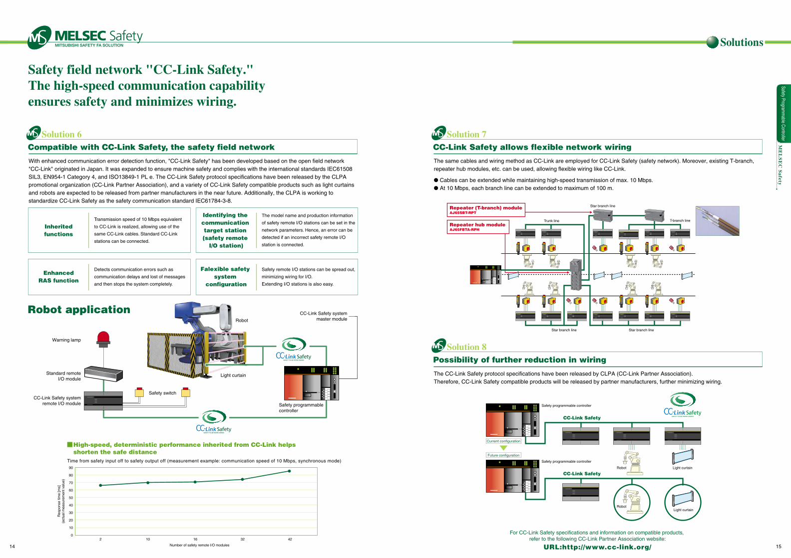
Safety field network "CC-Link Safety."The high-speed communication capability ensures safety and minimizes wiring.
Inheritedfunctions
Warning lamp
Robot
Light curtain
Safety switchCC-Link Safety system
remote I/O module Safety programmable controller
Standard remoteI/O module
CC-Link Safety systemmaster module
Robot application
Identifying the communication target station (safety remote
I/O station)
The model name and production information
of safety remote I/O stations can be set in the
network parameters. Hence, an error can be
detected if an incorrect safety remote I/O
station is connected.
Transmission speed of 10 Mbps equivalent
to CC-Link is realized, allowing use of the
same CC-Link cables. Standard CC-Link
stations can be connected.
EnhancedRAS function
Detects communication errors such as
communication delays and lost of messages
and then stops the system completely.
Falexible safety system
configuration
Safety remote I/O stations can be spread out,
minimizing wiring for I/O.
Extending I/O stations is also easy.
With enhanced communication error detection function, "CC-Link Safety" has been developed based on the open field network "CC-Link" originated in Japan. It was expanded to ensure machine safety and complies with the international standards IEC61508 SIL3, EN954-1 Category 4, and ISO13849-1 PL e. The CC-Link Safety protocol specifications have been released by the CLPA promotional organization (CC-Link Partner Association), and a variety of CC-Link Safety compatible products such as light curtains and robots are expected to be released from partner manufacturers in the near future. Additionally, the CLPA is working to standardize CC-Link Safety as the safety communication standard IEC61784-3-8.
URL:http://www.cc-link.org/
Solutions
Time from safety input off to safety output off (measurement example: communication speed of 10 Mbps, synchronous mode)90
80
70
60
50
40
30
20
10
02 10 16 32 42
Number of safety remote I/O modules
Res
pons
e tim
e [m
s](a
ctua
l mea
sure
men
t val
ue)
High-speed, deterministic performance inherited from CC-Link helps shorten the safe distance
ME
LS
EC
Safety
Solution 6Compatible with CC-Link Safety, the safety field network
Solution 7CC-Link Safety allows flexible network wiring
Solution 8Possibility of further reduction in wiring
Star branch lineStar branch line
Star branch line
Trunk line T-branch line
Repeater (T-branch) moduleAJ65SBT-RPT
Repeater hub moduleAJ65FBTA-RPH
Safety programmable controller
Robot Light curtain
Light curtainRobot
Safety programmable controller
CC-Link Safety
CC-Link Safety
Current configuration
Future configuration
The same cables and wiring method as CC-Link are employed for CC-Link Safety (safety network). Moreover, existing T-branch, repeater hub modules, etc. can be used, allowing flexible wiring like CC-Link.
Cables can be extended while maintaining high-speed transmission of max. 10 Mbps. At 10 Mbps, each branch line can be extended to maximum of 100 m.
The CC-Link Safety protocol specifications have been released by CLPA (CC-Link Partner Association). Therefore, CC-Link Safety compatible products will be released by partner manufacturers, further minimizing wiring.
Safety Programm
able Controller
14 15
For CC-Link Safety specifications and information on compatible products, refer to the following CC-Link Partner Association website:
Setting Examples
ME
LS
EC
Safety
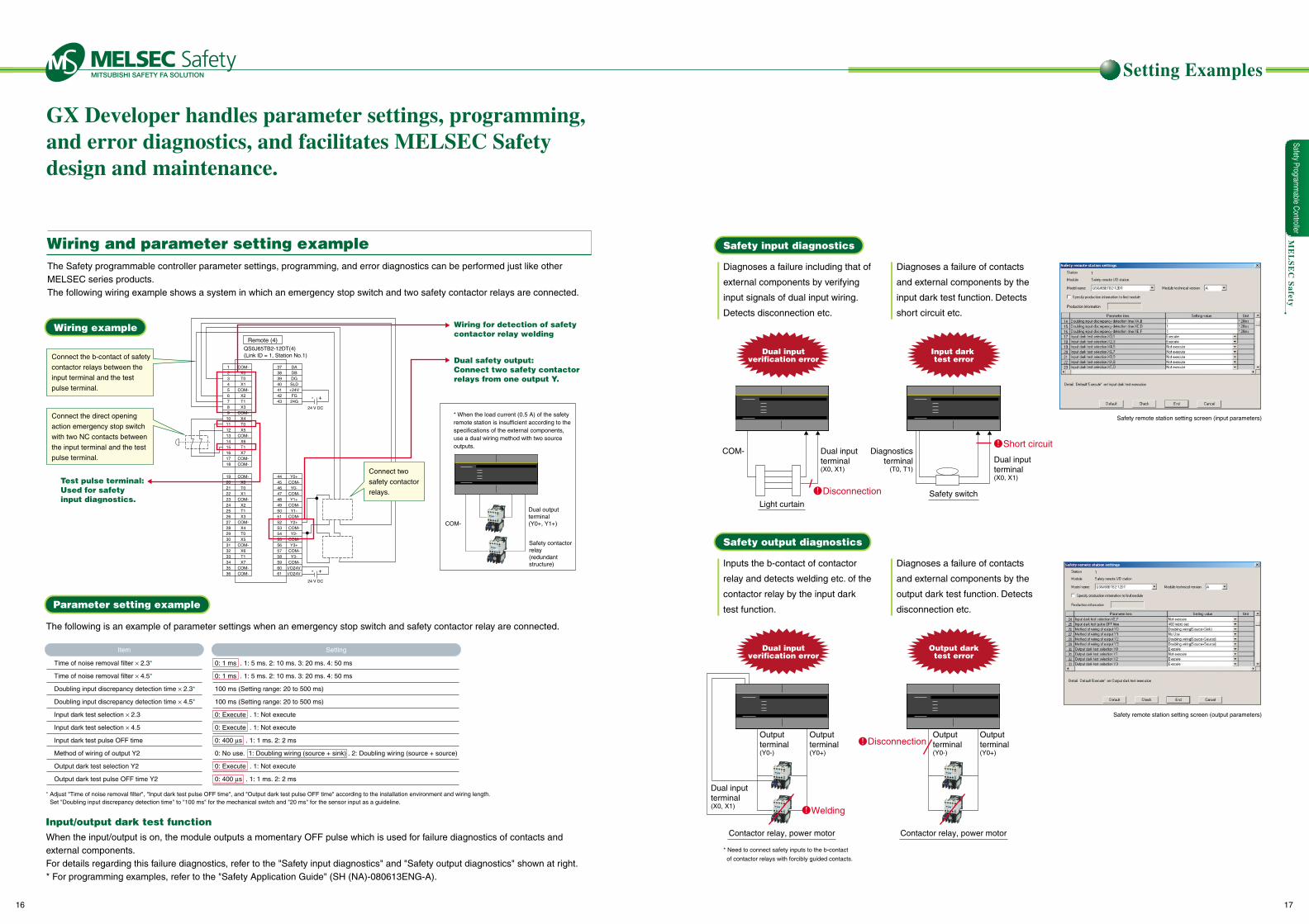
GX Developer handles parameter settings, programming, and error diagnostics, and facilitates MELSEC Safety design and maintenance.
Wiring and parameter setting example
Wiring example
Parameter setting example
Connect two
safety contactor
relays.
Connect the b-contact of safety
contactor relays between the
input terminal and the test
pulse terminal.
Connect the direct opening
action emergency stop switch
with two NC contacts between
the input terminal and the test
pulse terminal.
Test pulse terminal: Used for safety input diagnostics.
Wiring for detection of safetycontactor relay welding
Dual safety output: Connect two safety contactor relays from one output Y.
* When the load current (0.5 A) of the safety remote station is insufficient according to the specifications of the external components, use a dual wiring method with two source outputs.
The following is an example of parameter settings when an emergency stop switch and safety contactor relay are connected.
When the input/output is on, the module outputs a momentary OFF pulse which is used for failure diagnostics of contacts and external components. For details regarding this failure diagnostics, refer to the "Safety input diagnostics" and "Safety output diagnostics" shown at right.* For programming examples, refer to the "Safety Application Guide" (SH (NA)-080613ENG-A).
Input/output dark test function
* Adjust "Time of noise removal filter", "Input dark test pulse OFF time", and "Output dark test pulse OFF time" according to the installation environment and wiring length. Set "Doubling input discrepancy detection time" to "100 ms" for the mechanical switch and "20 ms" for the sensor input as a guideline.
Time of noise removal filter × 2.3*
Time of noise removal filter × 4.5*
Doubling input discrepancy detection time × 2.3*
Doubling input discrepancy detection time × 4.5*
Input dark test selection × 2.3
Input dark test selection × 4.5
Input dark test pulse OFF time
Method of wiring of output Y2
Output dark test selection Y2
Output dark test pulse OFF time Y2
0: 1 ms . 1: 5 ms. 2: 10 ms. 3: 20 ms. 4: 50 ms
0: 1 ms . 1: 5 ms. 2: 10 ms. 3: 20 ms. 4: 50 ms
100 ms (Setting range: 20 to 500 ms)
100 ms (Setting range: 20 to 500 ms)
0: Execute . 1: Not execute
0: Execute . 1: Not execute
0: 400 µs . 1: 1 ms. 2: 2 ms
0: No use. 1: Doubling wiring (source + sink) . 2: Doubling wiring (source + source)
0: Execute . 1: Not execute
0: 400 µs . 1: 1 ms. 2: 2 ms
Item Setting
Safety input diagnostics
Safety output diagnostics
Safety remote station setting screen (input parameters)
Safety remote station setting screen (output parameters)
* Need to connect safety inputs to the b-contact
of contactor relays with forcibly guided contacts.
Dual output terminal(Y0+, Y1+)
Dual input terminal(X0, X1)
Dual input terminal(X0, X1)
Diagnosticsterminal
(T0, T1)
Output terminal(Y0-)
Output terminal(Y0-)
Output terminal(Y0+)
Output terminal(Y0+)
Dual input terminal(X0, X1)
Safety contactor relay (redundant structure)
COM-
COM-
Light curtain
Contactor relay, power motor Contactor relay, power motor
Safety switch
Dual inputverification error
Dual inputverification error
Output darktest error
Input dark test error
Disconnection
Welding
Disconnection
Short circuit
Y0+COM-Y0-
COM-Y1+
COM-Y1-
COM-Y2+
COM-Y2-
COM-Y3+
COM-Y3-
COM-I/O24VI/O24V
QS0J65TB2-12DT(4) (Link ID = 1, Station No.1)
123456789101112131415161718
COM-X0T0X1
COM-X2T1X3
COM-X4T0X5
COM-X6T1X7
COM-COM-
37383940414243
444546474849505152535455565758596061
DADBDGSLD+24VFG24G
192021222324252627282930313233343536
COM-X0T0X1
COM-X2T1X3
COM-X4T0X5
COM-X6T1X7
COM-COM-
- +
24 V DC
- +
24 V DC
Remote (4)
The Safety programmable controller parameter settings, programming, and error diagnostics can be performed just like other MELSEC series products. The following wiring example shows a system in which an emergency stop switch and two safety contactor relays are connected.
Diagnoses a failure including that of
external components by verifying
input signals of dual input wiring.
Detects disconnection etc.
Inputs the b-contact of contactor
relay and detects welding etc. of the
contactor relay by the input dark
test function.
Diagnoses a failure of contacts
and external components by the
input dark test function. Detects
short circuit etc.
Diagnoses a failure of contacts
and external components by the
output dark test function. Detects
disconnection etc.
Safety Programm
able Controller
16 17
Application Examples
ME
LS
EC
Safety
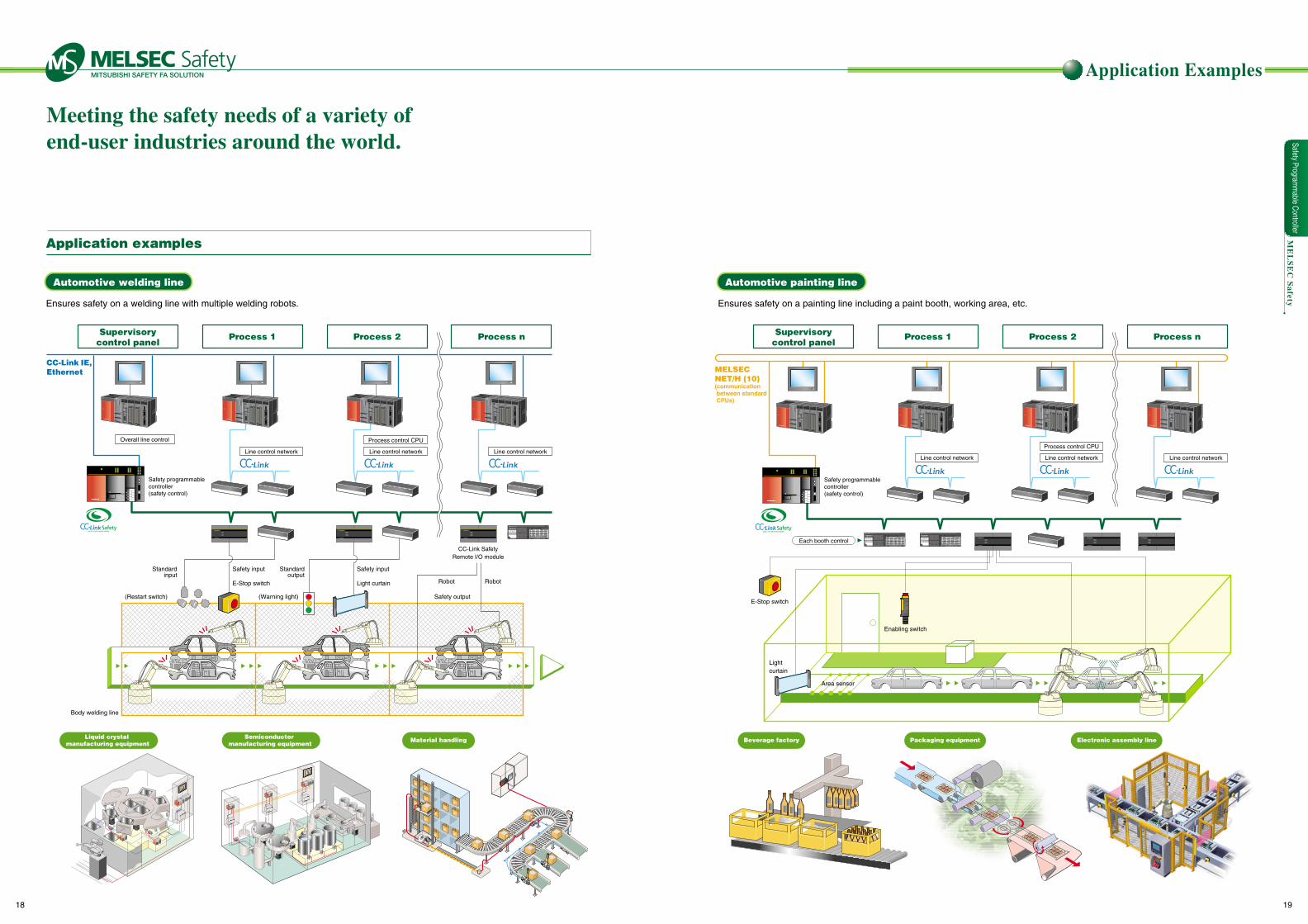
Meeting the safety needs of a variety of end-user industries around the world.
Application examples
Automotive welding line Automotive painting line
Supervisorycontrol panel
Process 1 Process 2 Process n Supervisorycontrol panel
Process 1 Process 2 Process n
Overall line control
Line control network Line control network
Process control CPU
Line control networkLine control network Line control network
Process control CPU
Line control network
Liquid crystal manufacturing equipment
Semiconductor manufacturing equipment
Material handling
Safety Programm
able Controller
18 19
Standardinput
E-Stop switch
Safety input Safety input
Safety output
Light curtain
Standardoutput
Robot Robot
QY42P
PULL
POWERQ25HCPU
USB
QY42P
PULL
MODERUNERR
USERBAT
BOOT
RS-232
QJ71LP21-25QY42P
PULL
POWERQ25HCPU
USB
QY42P
PULL
MODERUNERR
USERBAT
BOOT
RS-232
QJ71LP21-25QY42P
PULL
POWERQ25HCPU
USB
QY42P
PULL
MODERUNERR
USERBAT
BOOT
RS-232
QJ71LP21-25QY42P
PULL
POWERQ25HCPU
USB
QY42P
PULL
MODERUNERR
USERBAT
BOOT
RS-232
QJ71LP21-25
(Restart switch) (Warning light)
Safety programmable controller (safety control)
QY42P
PULL
POWERQ25HCPU
USB
QY42P
PULL
MODERUNERR
USERBAT
BOOT
RS-232
QJ71LP21-25QY42P
PULL
POWERQ25HCPU
USB
QY42P
PULL
MODERUNERR
USERBAT
BOOT
RS-232
QJ71LP21-25QY42P
PULL
POWERQ25HCPU
USB
QY42P
PULL
MODERUNERR
USERBAT
BOOT
RS-232
QJ71LP21-25QY42P
PULL
POWERQ25HCPU
USB
QY42P
PULL
MODERUNERR
USERBAT
BOOT
RS-232
QJ71LP21-25
Safety programmable controller (safety control)
AJ65SBT-CLB
40 20 108 4 2 14 2 12 1 2 12 1
PWL RUNL ERR.
STATION NO.B RATENOSTSTMODEB RATENC
ONCC-Link
CC-Link/LT
1 2 3 4 5 6 7 8 9 10 1 2 3 4 5 6 7 8
CC-LinkL RUNL ERR.L ERR.
CC-Link/LT
CC-Link
CC-Link/LT
AJ65SBT-CLB
40 20 108 4 2 14 2 12 1 2 12 1
PWL RUNL ERR.
STATION NO.B RATENOSTSTMODEB RATENC
ONCC-Link
CC-Link/LT
1 2 3 4 5 6 7 8 9 10 1 2 3 4 5 6 7 8
CC-LinkL RUNL ERR.L ERR.
CC-Link/LT
CC-Link
CC-Link/LT
QJ71E71-100
Q01CPU
RUN
ERR
PULL
RS-232
QJ71C24-R2QJ61BT-11
Q61SP
QJ71E71-100
Q01CPU
RUN
ERR
PULL
RS-232
QJ71C24-R2QJ61BT-11
Q61SP
PPC-HDD-5
CONTEC
QJ71E71-100
QJ71C24-R2
QJ61BT-11QJ61BT-11
QJ71WS96
QY42P
QX42-S1
PULL
Q25HCPU
MODE
RUN
ERR
USER
BAT
BOOT
POWER
Q61P-A1
Q12PHCPU
MODE
RUN
ERR
USER
BAT
BOOT
Q172CPU
MODE
RUN
ERR
USER
BAT
BOOT
USBUSBPULL
RS-232
USBUSBPULL
RS-232
USBUSBPULL
CH1
CH2FRONT
SSCNET
RS-232
PPC-CPU686
CONTEC
AJ65SBT-CLB
40 20 108 4 2 14 2 12 12 12 1
PWL RUNL ERR.STATION NO.B RATENOSTSTMODEB RATENC
ON
CC-Link
CC-Link/LT 1 2 3 4 5 6 7 8 9 10 1 2 3 4 5 6 7 8
CC-Link L RUNL ERR.L ERR.CC-Link/LT
CC-LinkCC-Link/LT
AJ65SBT-CLB
40 20 108 4 2 14 2 12 12 12 1
PWL RUNL ERR.STATION NO.B RATENOSTSTMODEB RATENC
ON
CC-Link
CC-Link/LT 1 2 3 4 5 6 7 8 9 10 1 2 3 4 5 6 7 8
CC-Link L RUNL ERR.L ERR.CC-Link/LT
CC-LinkCC-Link/LT
Q172CPU
MODE
RUN
ERR
USERBAT
BOOT
USBUSBPULL
CH1
CH2FRONT
SSCNET
RS-232
QJ61BT-11
PULL
POWER
Q64P-A1
Q12HCPU
MODE
RUN
ERR
USERBAT
BOOT
USBUSBPULL
RS-232
QJ71LP21-25
Q172CPU
MODE
RUN
ERR
USERBAT
BOOT
USBUSBPULL
CH1
CH2FRONT
SSCNET
RS-232
QJ61BT-11
PULL
POWER
Q64P-A1
Q12HCPU
MODE
RUN
ERR
USERBAT
BOOT
USBUSBPULL
RS-232
QJ71LP21-25
PULL
POWER
Q64P
PPC-HDD-5
CONTEC
Q172CPU
MODE
RUN
ERR
USERBAT
BOOT
USBUSBPULL
CH1
CH2FRONT
SSCNET
RS-232
PPC-CPU686
CONTEC
QJ71C24-R2
QJ61BT-11
Q25HCPU
MODE
RUN
ERR
USERBAT
BOOT
USBUSBPULL
RS-232
QJ71LP21-25
QJ61CL12
ON
TESTMODEB RATE
87654321
SW
POINTSI/O
E-Stop switch
Area sensorArea sensorArea sensor
NC
NCNC Y2+ NC Y2- NC Y3+ NC Y3-Y1-NCY1+NCNC Y0-Y0+NC
COM- I/O 24GI/O 24VNC
321Y0
x1x10
SETRESET
B RATESTATION NO.
432
10987
0 123
456
0 123
456
10
6 5 4
237
ELLBT
LINK ID
RD
SD
L ERR.
L RUN
ERR.
SAFETY
RUN
POWER(FG)SLDDB
24G+24VDGDA
QS0J65BTS2-4T
NC
NCNC Y2+ NC Y2- NC Y3+ NC Y3-Y1-NCY1+NCNC Y0-Y0+NC
COM- I/O 24GI/O 24VNC
321Y0
x1x10
SETRESET
B RATESTATION NO.
432
10987
0 123
456
0 123
456
10
6 5 4
237
ELLBT
LINK ID
RD
SD
L ERR.
L RUN
ERR.
SAFETY
RUN
POWER(FG)SLDDB
24G+24VDGDA
QS0J65BTS2-4T
NC
NCNC Y2+ NC Y2- NC Y3+ NC Y3-Y1-NCY1+NCNC Y0-Y0+NC
COM- I/O 24GI/O 24VNC
321Y0
x1x10
SETRESET
B RATESTATION NO.
432
10987
0 123
456
0 123
456
10
6 5 4
237
ELLBT
LINK ID
RD
SD
L ERR.
L RUN
ERR.
SAFETY
RUN
POWER(FG)SLDDB
24G+24VDGDA
QS0J65BTS2-4T
Ensures safety on a welding line with multiple welding robots. Ensures safety on a painting line including a paint booth, working area, etc.
Each booth controlCC-Link Safety
Remote I/O module
Enabling switch
CC-Link IE,Ethernet MELSEC
NET/H (10) (communication between standard CPUs)
Body welding line
Lightcurtain
Packaging equipment Electronic assembly lineBeverage factory
Specifications
ME
LS
EC
Safety
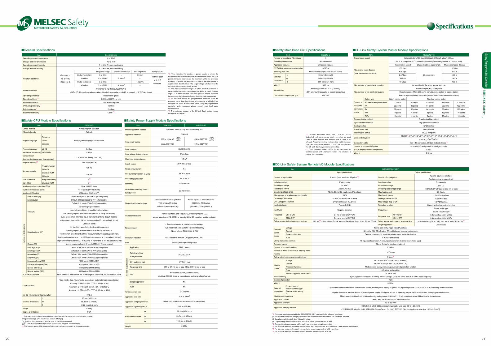
Operating ambient temperature
Storage ambient temperature
Operating ambient humidity
Storage ambient humidity
Vibration resistance
Shock resistance
Operating ambience
Operating altitude*3
Installation location
Overvoltage category*1
Pollution degree*2
Equipment category
Specifications
0 to 55°C
-40 to 75°C
5 to 95% RH, non-condensing
5 to 95% RH, non-condensing
Conforms to JIS B 3502, IEC61131-2
(147 m/s2, 11 ms shock pulse duration, shine half-wave pulse applied 3 times each in X, Y, Z directions.)
No corrosive gases
2,000 m (6562 ft.) or less
Inside control panel
II or less
2 or less
Class I*4
Conforms to
JIS B 3502,
IEC61131-2
Under intermittent
vibration
Under continuous
vibration
Frequency range
5 to 9 Hz
9 to 150 Hz
5 to 9 Hz
9 to 150 Hz
Constant acceleration
–
9.8 m/s2
–
4.9 m/s2
Half amplitude
3.5 mm
–
1.75 mm
–
Sweep count
10 times each
in X, Y, Z
directions
Mounting position on base
Applicable base unit
Input power supply
Input frequency
Input voltage distortion factor
Max. input apparent power
Inrush current
Rated output current
Overcurrent protection
Overvoltage protection
Efficiency
Allowable momentary power
failure period
Dielectric withstand voltage
Insulation resistance
Noise immunity
Operation indication
Fuse
Terminal screw size
Applicable wire size
Applicable crimping terminal
Applicable tightening torque
Weight
Application
Rated switching
voltage/current
Min. switching load
Response time
Life
Surge suppressor
Fuse
5 V DC
H
W
D
QS Series power supply module mounting slot
QS034B
50/60 Hz ± 5%
5% or less
125 VA
20 A 8 ms or less
6 A
6.6 A or more
5.5 to 6.5 V
70% or more
20 ms or less
Across Inputs/LG and outputs/FG, across inputs and LG,
across outputs and FG: 10 MΩ or more by 500 V DC insulation resistance tester
• By noise simulator of 1500 Vp-p noise voltage,
1 µs pulse width, and 25 to 60 Hz noise frequency
• Noise voltage IEC61000-4-4, 2 kV
LED indicators (Normal: ON [green]; error: OFF)
Built-in (unchangeable by user)
ERR. contact
24 V DC, 0.5 A
5 V DC, 1 mA
OFF to ON: 10 ms or less, ON to OFF: 12 ms or less
Mechanical: 20,000,000 times more;
electrical: 100,000 times or more at rated switching voltage/current.
No
No
M3.5 screw
0.75 to 2 mm2
RAV1.25-3.5, RAV2-3.5 (thickness of 0.8 mm or less)
0.66 to 0.89 N·m
98 mm (3.86 inch)
55.2 mm (2.17 inch)
115 mm (4.53 inch)
0.40 kg
100 to 120 V AC
(85 to 132 V AC)
+10%–15%
+10%–15%200 to 240 V AC
(170 to 264 V AC)
Item QS061P-A1 QS061P-A2
Control method
I/O control mode
Program language
Processing speed
(sequence instruction)
Constant scan
(function that keeps scan time constant)
Program capacity*1
Memory capacity
Max. number of
stored files
Number of writes to standard ROM
Number of I/O device points
Number of I/O points
RUN/PAUSE contact
Clock function
5 V DC internal current consumption
External dimensions
Weight
Degree of protection
Internal relay [M]
Link relay [B]
Timer [T]
Retentive timer [ST]
Counter [C]
Data register [D]
Link register [W]
Annunciator [F]
Edge relay [V]
Link special relay [SB]
Link special register [SW]
Special relay [SM]
Special register [SD]
Sequence
control
language
LD X0
MOV D0 D1
Program memory
(Drive 0)
Standard ROM
(Drive 4)
Program memory
Standard ROM
H
W
D
Cyclic program execution
Refresh
Relay symbol language, function block
0.10 µs
0.35 µs
1 to 2,000 ms (setting unit: 1 ms)
14 k steps (56 KB)
128 KB
128 KB
3*2
3*2
Max. 100,000 times
6144 points (X/Y0 to 17FF)
1024 points (X/Y0 to 3FF)
Default: 6144 points (M0 to 6143) (changeable)
Default: 2048 points (B0 to 7FF) (changeable)
Default: 512 points (T0 to 511) (changeable)
(for low-/high-speed timer)
Low-/high-speed timer is specified by instructions.
The low-/high-speed timer measurement unit is set by parameters.
(Low-speed timer: 1 to 1000 ms, in increments of 1 ms; default: 100 ms)
(High-speed timer: 0.1 to 100 ms, in increments of 0.1 ms; default: 10 ms)
Default: 0 points
(for low-/high-speed retentive timer) (changeable)
Low-/high-speed retentive timer is specified by instructions.
The low-/high-speed retentive timer measurement unit is set by parameters.
(Low-speed retentive timer: 1 to 1000 ms, in increments of 1 ms; default: 100 ms)
(High-speed retentive timer: 0.1 to 100 ms, in increments of 0.1 ms; default: 10 ms)
Normal counter default: 512 points (C0 to 511) (changeable)
Default: 6144 points (D0 to 6143) (changeable)
Default: 2048 points (W0 to 7FF) (changeable)
Default: 1024 points (F0 to 1023) (changeable)
Default: 1024 points (V0 to 1023) (changeable)
1536 points (SB0 to 5FF)
1536 points (SW0 to 5FF)
5120 points (SM0 to 5119)
5120 points (SD0 to 5119)
RUN contact: 1 point can be set in the range of X0 to 17FF, PAUSE contact: None
Year, month, date, hour, minute, second, day (automatic leap-year detection)
Accuracy: -3.18 to +5.25 s (TYP. +2.14 s)/d at 0°C
Accuracy: -3.18 to +2.59 s (TYP. +2.07 s)/d at 25°C
Accuracy: -12.97 to +3.63 s (TYP. +3.16 s)/d at 55°C
0.43 A
98 mm (3.86 inch)
55.2 mm (2.17 inch)
113.8 mm (4.48 inch)
0.29 kg
IP2X
Item
Item
QS001CPU
Num
ber o
f dev
ice
poin
ts
Con
tact
out
put s
ectio
n
*1: This indicates the section of power supply to which the
equipment is assumed to be connected between the public electrical
power distribution network and the machinery within the premises.
Category II applies to equipment for which electrical power is
supplied from fixed facilities. The surge voltage withstand level for
up to the rated voltage of 300 V is 2500 V.
*2: This index indicates the degree to which conductive material is
generated in the environment where the device is used. Pollution
degree 2 is when only non-conductive pollution occurs. However,
temporary conductivity caused by condensation is to be expected.
*3: Do not store or use the programmable controller under the
pressure higher than the atmospheric pressure of altitude 0 m.
Doing so can cause a malfunction. When using the programmable
controller under pressure, please consult your local sales
representative.
*4: The equipment category of the CC-Link Safety system remote
I/O module is Class III.
*1: The maximum number of executable sequence steps is calculated using the following formula:
(Program capacity) - (File header size [default: 34 steps])
For details of program capacity and file, refer to the following manual.
QSCPU User's Manual (Function Explanations, Program Fundamentals).
*2: The memory stores 1 file for each of parameter, sequence program, and device comment.
External dimensions
General Specifications
Safety Power Supply Module SpecificationsSafety CPU Module Specifications
Across inputs/LG and outputs/FG
2830 Vrms AC/3 cycles
(Altitude: 2,000 m [6562 ft.])
Across inputs/LG and outputs/FG
1780 Vrms AC/3 cycles
(Altitude: 2,000 m [6562 ft.])
Number of mountable I/O modules
Possibility of extension
Applicable modules
5 V DC internal current consumption
Mounting hole size
External
dimensions
Weight
Accessories
DIN rail mounting adaptor type
H
W
D
4
Not extendable
QS Series modules
0.095 A
M4 screw hole or φ4.5 hole (for M4 screw)
98 mm (3.86 inch)
245 mm (9.65 inch)
44.1 mm (1.74 inch)
0.28 kg
Mounting screws M4 × 14 (4 screws)
(DIN rail mounting adaptor to be sold separately)
Q6DIN2
Item QS034B-E
Number of input points
Isolation method
Rated input voltage
Rated input current
Operating voltage range
Max. number of simultaneous input points
On voltage/ON current
OFF voltage/OFF current
Input resistance
Input type
Response
time
Safety remote station input response time
External
power
supply*1
Wiring method for common
Common current
Number of occupied stations
Number of writes to nonvolatile memory inside
module
Safety refresh response processing time
Module
power*1
Noise immunity
Degree of protection
Weight
Module mounting screw
Applicable DIN rail
Applicable wire size
Applicable crimping terminal
Number of output points
Isolation method
Rated load voltage
Operating load voltage range
Max. load current
Max. inrush current
Leakage current at OFF
Max. voltage drop at ON
Protection function
Output type
Response time
Safety remote station output response time
Surge suppressor
OFF to ON
ON to OFF
Voltage
Current
Protection function
Fuse
Voltage
Current
Protection function
Fuse
Momentary power failure period
OFF to ON
ON to OFF
8 points (input terminals: 16 points*2)
Photocoupler
24 V DC
Approx. 4.6 mA
19.2 to 28.8 V DC (ripple ratio: 5% or less)
100%
15 V DC or more/2 mA or more
5 V DC or less/0.5 mA or less
Approx. 5.6 kΩ
Negative common
0.4 ms or less (at 24 V DC)
0.4 ms or less (at 24 V DC)
11.2 ms*3 or less + time of noise removal filter (1 ms, 5 ms, 10 ms, 20 ms, 50 ms)
19.2 to 28.8 V DC (ripple ratio: 5% or less)
60 mA (at 24 V DC, all points ON, not including external load current)
External power supply overvoltage/overcurrent protection function
8 A (not replaceable)
16 input points/common, 4 output points/common (terminal block 2-wire type)
Max. 4 A (total of inputs and outputs)
1 station
1012 times
9.6 ms*5
19.2 to 28.8 V DC (ripple ratio: 5% or less)
140 mA or less (at 24 V DC, all points ON)
Module power supply overvoltage/overcurrent protection function
0.8 A (not replaceable)
10 ms or less
By DC-type noise simulator of 500 Vp-p noise voltage, 1µs pulse width, and 25 to 60 Hz noise frequency
IP2X
0.67 kg
M4 screw with polished, round flat washer (tightening torque: 0.824 to 1.11 N·m); mountable with a DIN rail, and in 6 orientations.
TH35-7.5Fe, TH35-7.5AI (JIS C 2812 compliant)
0.3 to 2.0 mm2
• RAV1.25-3 (JIS C 2805 compliant) [applicable wire size: 0.3 to 1.25 mm2]
• V2-MS3 (JST Mfg. Co., Ltd.), RAP2-3SL (Nippon Tanshi Co., Ltd.), TGV2-3N (Nichifu) [applicable wire size: 1.25 to 2.0 mm2]
4 points (source + sink type)
2 points (source + source type)
Photocoupler
24 V DC
19.2 to 28.8 V DC (ripple ratio: 5% or less)
0.5 A/point
1.0 A 10 ms or less
0.5 mA or less
1.0 V DC or less
Output overload protection function
Source + sink type
Source + source type
0.4 ms or less (at 24 V DC)
0.4 ms or less (at 24 V DC)
10.4 ms or less (ON to OFF), 11.2 ms or less (OFF to ON)*4
Zener diode
Input specifications Output specifications
Item QS0J65BTB2-12DT
*1: CC-Link dedicated cable (Ver. 1.00) or CC-Link
dedicated high-performance cable can also be used.
Using a cable together with another type of cable is not
allowed. Attach terminating resistors that match the cable
type. Two terminating resistors (110 Ω) are included with
the CC-Link Safety system master module.
*2: Error detection using CRC32 is not performed for
communication with standard remote I/O stations or
remote device stations.
*1: The power supply connected to the QS0J65BTB2-12DT must satisfy the following conditions:
(1) SELV (Safety Extra Low Voltage): Reinforced insulation from hazardous areas (48 V or more) required.
(2) Compliance with the LVD (Low Voltage Directive).
(3) Output voltage specification must be 19.2 to 28.8 V DC (ripple rate: 5% or less).
*2: Two input terminals are assigned for each input since dual wiring is supported.
*3: For technical version A, the safety remote station input response time is 32 ms or less + time of noise removal filter.
*4: For technical version A, the safety remote station output response time is 32 ms or less.
*5: For technical version A, the safety refresh response processing time is 38 ms.
External
connections
Communication,module power supply
External power supply,I/O
7-point detachable terminal block [transmission circuits, module power supply, FG] M3 × 5.2; tightening torque: 0.425 to 0.575 N·m; 2 crimping terminals or less
18-point detachable terminal block × 3 [external power supply, I/O signals] M3 × 5.2; tightening torque: 0.425 to 0.575 N·m; 2 crimping terminals or less
Transmission speed
Max. overall cable distance
(max. transmission distance)
Max. number of connectable modules
Max. number of link points per system
Number of
link points
per remote
station
Communication method
Synchronization method
Coding method
Transmission path
Transmission format
Error control system
Connection cable
Number of occupied I/O points
5 V DC internal current consumption
Weight
Selectable from 156 kbps/625 kbps/2.5 Mbps/5 Mbps/10 Mbps
Ver. 1.10 compatible, CC-Link dedicated cable (Terminating resistor of 110 Ω is used)
64 modules (42 for safety remote stations)
Remote I/O (RX, RY): 2048 points
Remote register (RWr): 256 points (remote device station to master station)
Remote register (RWw): 256 points (master station to remote device station)
Broadcast polling method
Flag synchronous method
NRZI method
Bus (RS-485)
HDLC compliant
CRC32*2 (X32+X26+X23+X22+X16+X12+X11+X10+X8+X7+X5+X4+X2+X+1)
CRC16 (X16+X12+X5+1)
Ver. 1.10 compatible, CC-Link dedicated cable*1
32 points (I/O assignment: 32 intelligent points)
0.46 A
0.12 kg
Safety remote station
1 station
32 points
32 points
0 points
0 points
1 station
32 points
32 points
4 points
4 points
2 stations
64 points
64 points
8 points
8 points
3 stations
96 points
96 points
12 points
12 points
4 stations
128 points
128 points
16 points
16 points
Standard remote stationStation type
Number of occupied stations
RX
RY
RWr
RWw
Item QS0J61BT12
Transmission speed
156 kbps
625 kbps
2.5 Mbps
5 Mbps
10 Mbps
Station-to-station cable length
20 cm or more
Max. overall cable distance
1200 m
900 m
400 m
160 m
100 m
Safety Main Base Unit Specifications
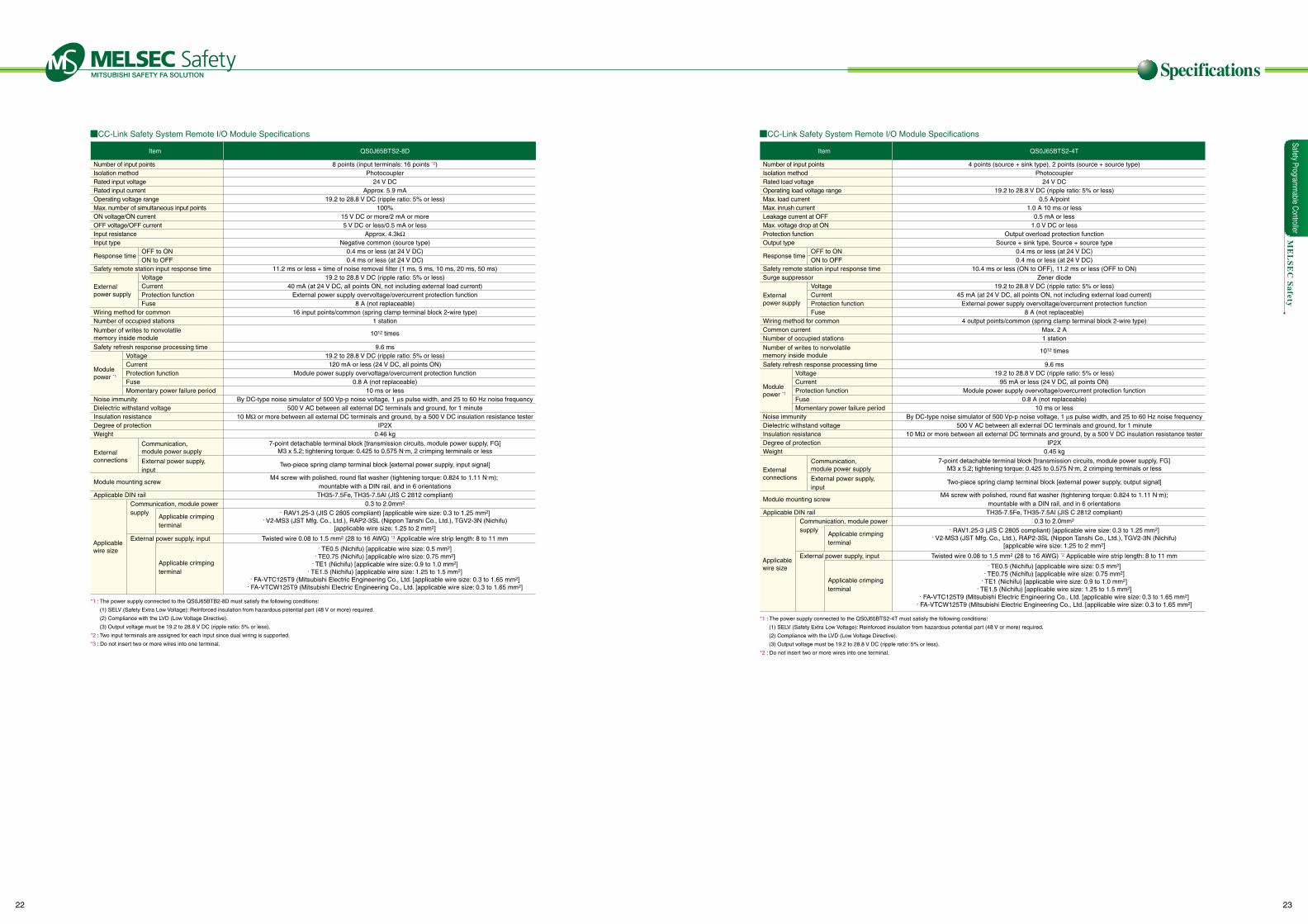
CC-Link Safety System Remote I/O Module Specifications
CC-Link Safety System Master Module Specifications
Safety Programm
able Controller
20 21
Specifications
ME
LS
EC
Safety
Number of input pointsIsolation methodRated input voltageRated input currentOperating voltage rangeMax. number of simultaneous input pointsON voltage/ON currentOFF voltage/OFF currentInput resistanceInput type
Safety remote station input response time
Wiring method for commonNumber of occupied stations
Safety refresh response processing time
Noise immunityDielectric withstand voltageInsulation resistanceDegree of protectionWeight
Module mounting screw
Applicable DIN rail
8 points (input terminals: 16 points *2)Photocoupler
24 V DCApprox. 5.9 mA
19.2 to 28.8 V DC (ripple ratio: 5% or less)100%
15 V DC or more/2 mA or more5 V DC or less/0.5 mA or less
Approx. 4.3kΩNegative common (source type)
0.4 ms or less (at 24 V DC)0.4 ms or less (at 24 V DC)
11.2 ms or less + time of noise removal filter (1 ms, 5 ms, 10 ms, 20 ms, 50 ms)19.2 to 28.8 V DC (ripple ratio: 5% or less)
40 mA (at 24 V DC, all points ON, not including external load current)External power supply overvoltage/overcurrent protection function
8 A (not replaceable)16 input points/common (spring clamp terminal block 2-wire type)
1 station
9.6 ms19.2 to 28.8 V DC (ripple ratio: 5% or less)120 mA or less (24 V DC, all points ON)
Module power supply overvoltage/overcurrent protection function0.8 A (not replaceable)
10 ms or lessBy DC-type noise simulator of 500 Vp-p noise voltage, 1 µs pulse width, and 25 to 60 Hz noise frequency
500 V AC between all external DC terminals and ground, for 1 minute10 MΩ or more between all external DC terminals and ground, by a 500 V DC insulation resistance tester
IP2X0.46 kg
M4 screw with polished, round flat washer (tightening torque: 0.824 to 1.11 N·m); mountable with a DIN rail, and in 6 orientations
TH35-7.5Fe, TH35-7.5Al (JIS C 2812 compliant)0.3 to 2.0mm2
Twisted wire 0.08 to 1.5 mm2 (28 to 16 AWG) *3 Applicable wire strip length: 8 to 11 mm
Item QS0J65BTS2-8D
*1 : The power supply connected to the QS0J65BTB2-8D must satisfy the following conditions:
(1) SELV (Safety Extra Low Voltage): Reinforced insulation from hazardous potential part (48 V or more) required.
(2) Compliance with the LVD (Low Voltage Directive).
(3) Output voltage must be 19.2 to 28.8 V DC (ripple ratio: 5% or less).
*2 : Two input terminals are assigned for each input since dual wiring is supported.
*3 : Do not insert two or more wires into one terminal.
Response time
Externalpower supply
External connections
Applicable wire size
Module power *1
Number of writes to nonvolatile memory inside module
OFF to ONON to OFF
Voltage CurrentProtection functionFuse
VoltageCurrentProtection functionFuseMomentary power failure period
Communication,module power supply
Applicable crimping terminal
Applicable crimping terminal
Communication, module power supply
External power supply, input
External power supply,input
1012 times
7-point detachable terminal block [transmission circuits, module power supply, FG]M3 x 5.2; tightening torque: 0.425 to 0.575 N·m, 2 crimping terminals or less
· TE0.5 (Nichifu) [applicable wire size: 0.5 mm2]· TE0.75 (Nichifu) [applicable wire size: 0.75 mm2]
· TE1 (Nichifu) [applicable wire size: 0.9 to 1.0 mm2]· TE1.5 (Nichifu) [applicable wire size: 1.25 to 1.5 mm2]
· FA-VTC125T9 (Mitsubishi Electric Engineering Co., Ltd. [applicable wire size: 0.3 to 1.65 mm2]· FA-VTCW125T9 (Mitsubishi Electric Engineering Co., Ltd. [applicable wire size: 0.3 to 1.65 mm2]
· RAV1.25-3 (JIS C 2805 compliant) [applicable wire size: 0.3 to 1.25 mm2]· V2-MS3 (JST Mfg. Co., Ltd.), RAP2-3SL (Nippon Tanshi Co., Ltd.), TGV2-3N (Nichifu)
[applicable wire size: 1.25 to 2 mm2]
Two-piece spring clamp terminal block [external power supply, input signal]
Number of input pointsIsolation methodRated load voltageOperating load voltage rangeMax. load currentMax. inrush currentLeakage current at OFFMax. voltage drop at ONProtection functionOutput type
Safety remote station input response timeSurge suppressor
Wiring method for commonCommon currentNumber of occupied stations
Safety refresh response processing time
Noise immunityDielectric withstand voltageInsulation resistanceDegree of protectionWeight
Module mounting screw
Applicable DIN rail
4 points (source + sink type), 2 points (source + source type)Photocoupler
24 V DC19.2 to 28.8 V DC (ripple ratio: 5% or less)
0.5 A/point1.0 A 10 ms or less
0.5 mA or less1.0 V DC or less
Output overload protection functionSource + sink type, Source + source type
0.4 ms or less (at 24 V DC)0.4 ms or less (at 24 V DC)
10.4 ms or less (ON to OFF), 11.2 ms or less (OFF to ON)Zener diode
19.2 to 28.8 V DC (ripple ratio: 5% or less)45 mA (at 24 V DC, all points ON, not including external load current)
External power supply overvoltage/overcurrent protection function8 A (not replaceable)
4 output points/common (spring clamp terminal block 2-wire type)Max. 2 A1 station
9.6 ms19.2 to 28.8 V DC (ripple ratio: 5% or less)
95 mA or less (24 V DC, all points ON)Module power supply overvoltage/overcurrent protection function
0.8 A (not replaceable)10 ms or less
By DC-type noise simulator of 500 Vp-p noise voltage, 1 µs pulse width, and 25 to 60 Hz noise frequency500 V AC between all external DC terminals and ground, for 1 minute
10 MΩ or more between all external DC terminals and ground, by a 500 V DC insulation resistance testerIP2X
0.45 kg
M4 screw with polished, round flat washer (tightening torque: 0.824 to 1.11 N·m);mountable with a DIN rail, and in 6 orientations
TH35-7.5Fe, TH35-7.5Al (JIS C 2812 compliant)0.3 to 2.0mm2
Twisted wire 0.08 to 1.5 mm2 (28 to 16 AWG) *2 Applicable wire strip length: 8 to 11 mm
Item QS0J65BTS2-4T
*1 : The power supply connected to the QS0J65BTS2-4T must satisfy the following conditions:
(1) SELV (Safety Extra Low Voltage): Reinforced insulation from hazardous potential part (48 V or more) required.
(2) Compliance with the LVD (Low Voltage Directive).
(3) Output voltage must be 19.2 to 28.8 V DC (ripple ratio: 5% or less).
*2 : Do not insert two or more wires into one terminal.
Response time
External power supply
External connections
Applicable wire size
Module power *1
Number of writes to nonvolatile memory inside module
OFF to ONON to OFF
VoltageCurrentProtection functionFuse
VoltageCurrentProtection functionFuseMomentary power failure period
Communication,module power supply
Applicable crimping terminal
Applicable crimping terminal
Communication, module power supply
External power supply, input
External power supply,input
1012 times
7-point detachable terminal block [transmission circuits, module power supply, FG]M3 x 5.2; tightening torque: 0.425 to 0.575 N·m, 2 crimping terminals or less
· TE0.5 (Nichifu) [applicable wire size: 0.5 mm2]· TE0.75 (Nichifu) [applicable wire size: 0.75 mm2]
· TE1 (Nichifu) [applicable wire size: 0.9 to 1.0 mm2]· TE1.5 (Nichifu) [applicable wire size: 1.25 to 1.5 mm2]
· FA-VTC125T9 (Mitsubishi Electric Engineering Co., Ltd. [applicable wire size: 0.3 to 1.65 mm2]· FA-VTCW125T9 (Mitsubishi Electric Engineering Co., Ltd. [applicable wire size: 0.3 to 1.65 mm2]
· RAV1.25-3 (JIS C 2805 compliant) [applicable wire size: 0.3 to 1.25 mm2]· V2-MS3 (JST Mfg. Co., Ltd.), RAP2-3SL (Nippon Tanshi Co., Ltd.), TGV2-3N (Nichifu)
[applicable wire size: 1.25 to 2 mm2]
Two-piece spring clamp terminal block [external power supply, output signal]
CC-Link Safety System Remote I/O Module Specifications CC-Link Safety System Remote I/O Module Specifications
Safety Programm
able Controller
22 23
Specifications
Unit: mm (inch)
QS0J65BTB2-12DT
QS0J65BTS2-8D
QS0J65BTS2-4T
Safety Programmable Controller Lineup
ME
LS
EC
Safety
47 (
1.85
)47
(1.8
5)
44 (
1.73
)56
(2.
20)
74.5
(2.
93)
44 (
1.73
)
74.5
(2.
93)
65 (
2.56
)
56 (
2.20
)
65 (
2.56
)
188.4 (7.42)
188.4 (7.42)
2-ø4.5M4
2-ø4.5M4
9 (0.35)
4.5 (0.18)
32.5
(1.2
8)
4.5 (0.18)
32.5
(1.2
8)
197 (7.76)
197 (7.76)
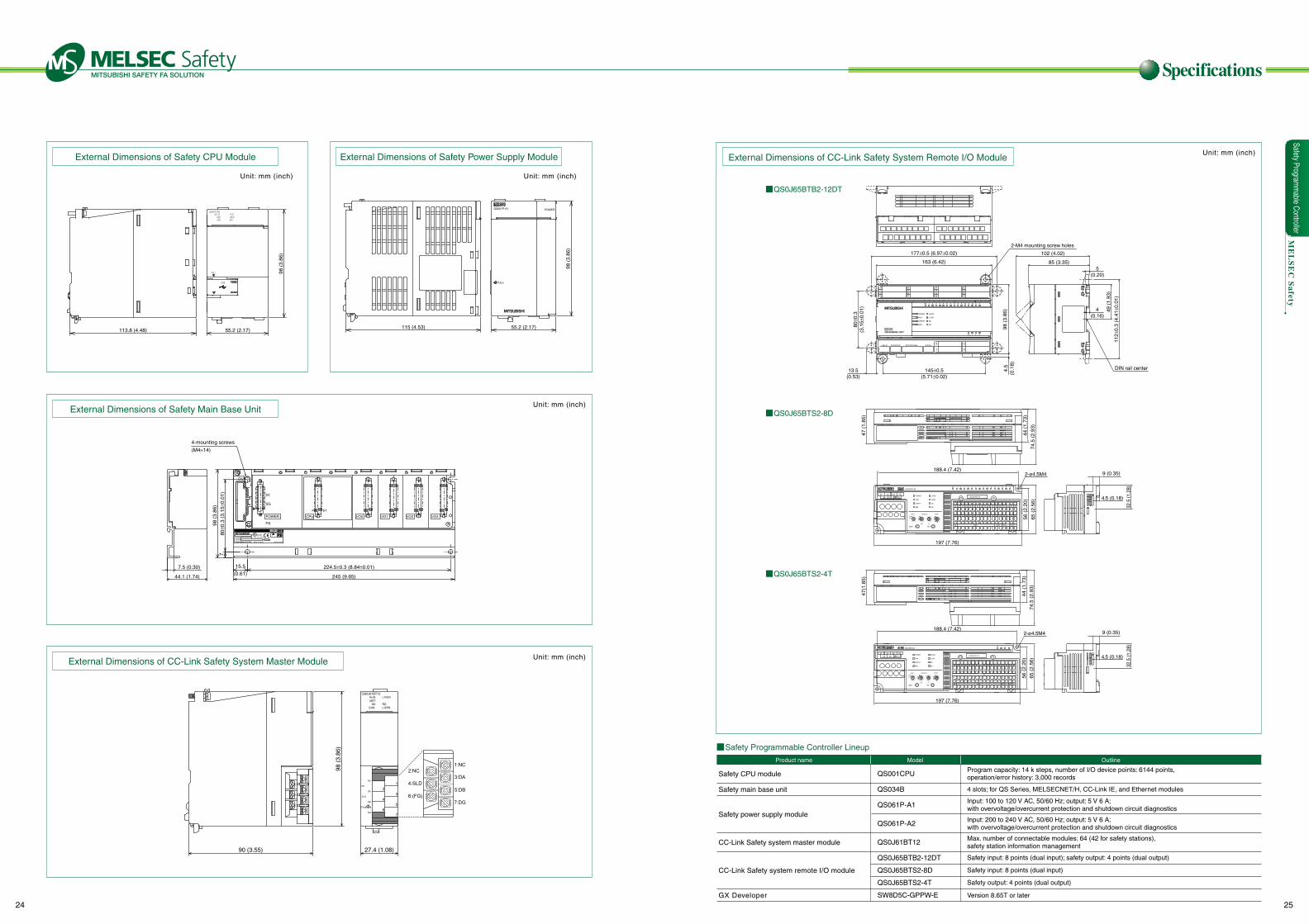
External Dimensions of Safety Power Supply ModuleExternal Dimensions of Safety CPU Module
Unit: mm (inch) Unit: mm (inch)
113.8 (4.48) 55.2 (2.17)
98 (
3.86
)
QS061P-A1 POWER
PULL
115 (4.53) 55.2 (2.17)
98 (
3.86
)
External Dimensions of Safety Main Base Unit
External Dimensions of CC-Link Safety System Master Module
OUT
5V
FG
I/O3I/O2I/O1I/O0CPUPOWER
SG
b1a1
245 (9.65)
224.5±0.3 (8.84±0.01)15.5(0.61)
780
±0.3
(3.
15±0
.01)
98 (
3.86
)
BD992C202H01
80M1 IND.CONT.E Q.
SERIALMODEL
MADE IN JAPAN
PASSED
4-mounting screws
(M4×14)
44.1 (1.74)
7.5 (0.30)
Unit: mm (inch)
Unit: mm (inch)
90 (3.55) 27.4 (1.08)
98 (
3.86
)
External Dimensions of CC-Link Safety System Remote I/O Module
POWER
RUN
SAFETY
ERR.
L.RUN
L.ERR.
SD
RD
LINK ID STATION NO. STATION NAME B RATE0
1
2
3
X0 1 2 3 4 5 6 7 8 9 A B C D E F
Y0 1 2 3
0123
4567
89AB
CDEF
2-M4 mounting screw holes
DIN rail center
163 (6.42)
145±0.5(5.71±0.02)
13.5(0.53)
177±0.5 (6.97±0.02)
98 (
3.86
)4.
5(0
.18)
80±0
.3(3
.15±
0.01
)
85 (3.35)
102 (4.02)
4(0.16)
49 (
1.93
)
5(0.20)
112±
0.3
(4.4
1±0.
01)
9 (0.35)
Safety CPU module
Safety main base unit
Safety power supply module
CC-Link Safety system master module
CC-Link Safety system remote I/O module
GX Developer
Product name Model Outline
QS001CPU
QS034B
QS061P-A1
QS061P-A2
QS0J61BT12
QS0J65BTB2-12DT
QS0J65BTS2-8D
QS0J65BTS2-4T
SW8D5C-GPPW-E Version 8.65T or later
Program capacity: 14 k steps, number of I/O device points: 6144 points,operation/error history: 3,000 records
4 slots; for QS Series, MELSECNET/H, CC-Link IE, and Ethernet modules
Input: 100 to 120 V AC, 50/60 Hz; output: 5 V 6 A; with overvoltage/overcurrent protection and shutdown circuit diagnostics
Input: 200 to 240 V AC, 50/60 Hz; output: 5 V 6 A; with overvoltage/overcurrent protection and shutdown circuit diagnostics
Max. number of connectable modules: 64 (42 for safety stations), safety station information management
Safety input: 8 points (dual input); safety output: 4 points (dual output)
Safety input: 8 points (dual input)
Safety output: 4 points (dual output)
Safety Programm
able Controller
24 25
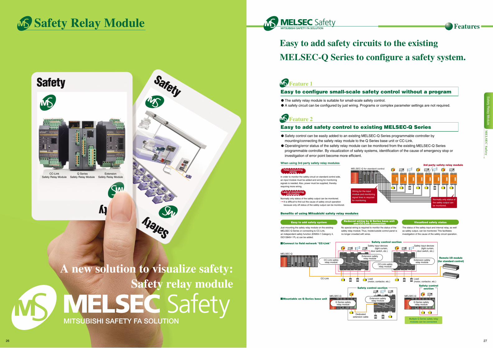
Q SeriesSafety Relay Module
CC-LinkSafety Relay Module
ExtensionSafety Relay Module
Feature 1Easy to configure small-scale safety control without a program
Feature 2Easy to add safety control to existing MELSEC-Q Series
Features
ME
LS
EC
Safety
When using 3rd party safety relay modules
Benefits of using Mitsubishi safety relay modules
ZX10X1
PW ERR.
QS90SR2SN-Q
K1K2
S PW
In order to monitor the safety circuit on standard control side, an input module must be added and wiring for monitoring signals is needed. Also, power must be supplied, thereby requiring more wiring.
Multiple Q Series safety relaymodules can be connected.
EXT.PW
EXT.PW
+24V
24G
(FG)
PULL
POWERQ61P ST.NO.
× 100 10 1
RUNMODE
SDERR.
PRMD LINKRD
QJ71GP21-SXQJ71E71-100RUNINIT
OPENSD
ERRCOM.ERR100MRD
10BASE-T/100BASE-TX
MELSEC-QEXT.PW
EXT.PW
+24V
24G
(FG)
ST.NO.
X 100 10 1
RUNMODE
SDERR.
PRMD LINKRD
QJ71GP21S-SX
PULL
POWERQ61P
QJ71LP21-25RUN
MODESD
ERR.
PRMD LINKRD
0123456789ABCDEF
QX40
0123456789ABCDEF
QY40PQJ61BT11N
STATION NO.
X10
X1
MODE
NC
DA
DB
DG
1
3
5
7
6
4
2
RUNMODE
SDERR.
PRMD LINKRD
ST.NO.
X 100 10 1
RUNMODE
SDERR.
PRMD LINKRD
QJ71GP21-SXQJ71E71-100RUNINIT
OPENSD
ERRCOM.ERR100MRD
10BASE-T/100BASE-TX
MELSEC-Q for standard control
MELSEC-QMELSEC-Q
PULL
POWERQ61P ST.NO.
X 100 10 1
RUNMODE
SDERR.
PRMD LINKRD
QJ71GP21-SXQJ71E71-100RUNINIT
OPENSD
ERRCOM.ERR100MRD
10BASE-T/100BASE-TX
Connect to field network "CC-Link"
Mountable on Q Series base unit
Easy to add safety system Reduced wiring by Q Series base unit and CC-Link connection Visualized safety status
Normally only status of the safety output can be monitored.It is difficult to find out the cause of safety circuit operation because only off status of the safety output can be monitored.
Lack of monitoringinformation
Time-consumingwiring
Just mounting the safety relay module on the existing MELSEC-Q Series or connecting to CC-Link, an independent safety function (EN954-1 Category 4, ISO13849-1 PL e) can be added.
No special wiring is required to monitor the status of the safety relay module. Thus, Inside/outside control panel is no longer crowded with wires.
The status of the safety input and internal relay, as well as safety output, can be monitored. This facilitates investigation of the cause of the safety circuit operation.
Safety control section
Safety controlsectionSafety control section
Remote I/O module(for standard control)
3rd party safety relay module
CC-Link safetyrelay module
Safety input devices(light curtain,
door switch, etc.)
Load (motor, contactor, etc.)
CC-Link
Safety input devices(light curtain,
door switch, etc.)
Load (motor, contactor, etc.)
Dedicatedextension cable
Normally only status of the safety output can be monitored.
Wiring for the input module and monitoring signal lines is required for monitoring.
QJ71LP21-25RUN
MODESD
ERR.
PRMD LINKRD
PULL
POWERQ61PQY42 QY42 QY42P
Extension safetyrelay module
CC-Link safetyrelay module
Extension safetyrelay module
Extension safetyrelay module
ZX10X1
PW ERR.
QS90SR2SN-Q
K1K2
S PWZX10X1
PW ERR.
QS90SR2SN-Q
K1K2
S PW
Q Series safetyrelay module
Q Series safetyrelay module
Safety Relay Module
A new solution to visualize safety:Safety relay module
Easy to add safety circuits to the existing
MELSEC-Q Series to configure a safety system.
The safety relay module is suitable for small-scale safety control. A safety circuit can be configured by just wiring. Programs or complex parameter settings are not required.
Safety control can be easily added to an existing MELSEC-Q Series programmable controller by mounting/connecting the safety relay module to the Q Series base unit or CC-Link.
Operating/error status of the safety relay module can be monitored from the existing MELSEC-Q Series programmable controller. By visualization of safety systems, identification of the cause of emergency stop or investigation of error point become more efficient.
Safety R
elay Module
26 27
MELSEC-Q
PULL
POWERQ61P ST.NO.
× 100 10 1
RUNMODESDERR.
PRMD LINKRD
QJ71GP21-SXQJ71E71-100RUNINITOPENSD
ERRCOM.ERR100MRD
10BASE-T/100BASE-TX
ZX10X1
PW ERR.
QS90SR2SN-Q
K1K2
S PW
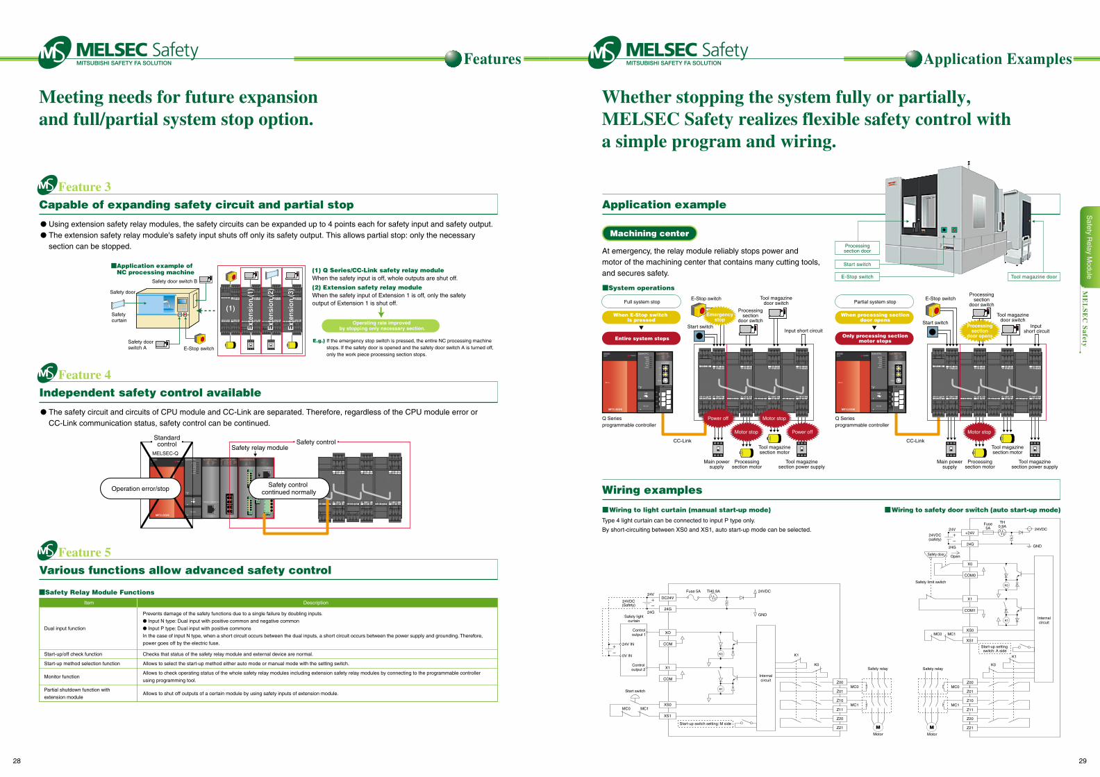
Feature 3Capable of expanding safety circuit and partial stop
Feature 4Independent safety control available
Feature 5Various functions allow advanced safety control
Safety relay module
Standardcontrol Safety control
Operation error/stop
Application example
Wiring examples
Machining center
At emergency, the relay module reliably stops power and motor of the machining center that contains many cutting tools, and secures safety.
X1
COMZ00
Z01
Z10
Z11
Z20
Z21
Start switch
24G
XO
COM
XS0
XS1
MC1
MC0
DC24V
Internalcircuit
MC0 MC1
Controloutput 1
Controloutput 2
24V IN
0V IN
24VDC(Safety)
24V
24GSafety light
curtain
GND
24VDC
K0
K1
MMotor
Safety relay
Fuse 5A TH0.9A
K1
K0
Start-up switch setting: M side
Wiring to light curtain (manual start-up mode) Wiring to safety door switch (auto start-up mode)
System operations
PULL
POWERQ61PQJ61BT11N
STATION NO.
X10
X1
MODE
NC
DA
DB
DG
1
3
5
7
6
4
2
RUNMODESDERR.
PRMD LINKRD
E-Stop switch
Start switch
Q Series programmable controller
CC-Link
Motor stop
Main powersupply
Processingsection motor
Tool magazinesection motor
Tool magazinesection power supply
Input short circuit
Tool magazinedoor switch
Processingsection
door switch
Processingsection
door opens
Partial system stop
When processing sectiondoor opens
Only processing sectionmotor stops
PULL
POWERQ61PQJ61BT11N
STATION NO.
X10
X1
MODE
NC
DA
DB
DG
1
3
5
7
6
4
2
RUNMODESDERR.
PRMD LINKRD
E-Stop switch
Q Series programmable controller
CC-Link
Motor stop Power off
Motor stopPower off
Main powersupply
Processingsection motor
Tool magazinesection motor
Tool magazinesection power supply
Input short circuit
Tool magazinedoor switch
Emergencystop
Full system stop
When E-Stop switch is pressedOperating rate improved
by stopping only necessary section.
Entire system stops
Start switch
Processingsection
door switch
Features Application Examples
ME
LS
EC
Safety
Safety door
Safety curtain
Safety door switch A
E.g.) If the emergency stop switch is pressed, the entire NC processing machine stops. If the safety door is opened and the safety door switch A is turned off, only the work piece processing section stops.
Safety door switch B When the safety input is off, whole outputs are shut off.
When the safety input of Extension 1 is off, only the safety output of Extension 1 is shut off.
Application example of NC processing machine (1) Q Series/CC-Link safety relay module
(2) Extension safety relay module
E-Stop switch
Start-up/off check function
Start-up method selection function
Monitor function
Partial shutdown function with
extension module
Dual input function
Checks that status of the safety relay module and external device are normal.
Allows to select the start-up method either auto mode or manual mode with the setting switch.
Allows to check operating status of the whole safety relay modules including extension safety relay modules by connecting to the programmable controller
using programming tool.
Allows to shut off outputs of a certain module by using safety inputs of extension module.
Prevents damage of the safety functions due to a single failure by doubling inputs.
Input N type: Dual input with positive common and negative common
Input P type: Dual input with positive commons
In the case of input N type, when a short circuit occurs between the dual inputs, a short circuit occurs between the power supply and grounding. Therefore,
power goes off by the electric fuse.
Safety Relay Module FunctionsItem Description
Type 4 light curtain can be connected to input P type only.
By short-circuiting between XS0 and XS1, auto start-up mode can be selected.
Safety relay
Z00
Z01
Z10
Z11
Z20
Z21
MC1
MC0
Internalcircuit
K0
MC0 MC1
MMotor
24G
+24V24V
24G GND
24VDC(safety)
OpenSafety door
Safety limit switch
24VDCFuse5A
TH0.9A
K1
K0
K1
Start-up setting switch: A side
XS0
XS1
COM1
X1
COM0
X0
Processingsection door
Start switch
Tool magazine doorE-Stop switch
Safety control continued normally
Meeting needs for future expansion and full/partial system stop option.
Whether stopping the system fully or partially, MELSEC Safety realizes flexible safety control with a simple program and wiring.
Using extension safety relay modules, the safety circuits can be expanded up to 4 points each for safety input and safety output. The extension safety relay module's safety input shuts off only its safety output. This allows partial stop: only the necessary
section can be stopped.
The safety circuit and circuits of CPU module and CC-Link are separated. Therefore, regardless of the CPU module error or CC-Link communication status, safety control can be continued.
Ext
ensi
on (1
)E
xten
sion
(1)
(1)(1)
Ext
ensi
on (2
)E
xten
sion
(2)
Ext
ensi
on (3
)E
xten
sion
(3)
Safety R
elay Module
28 29
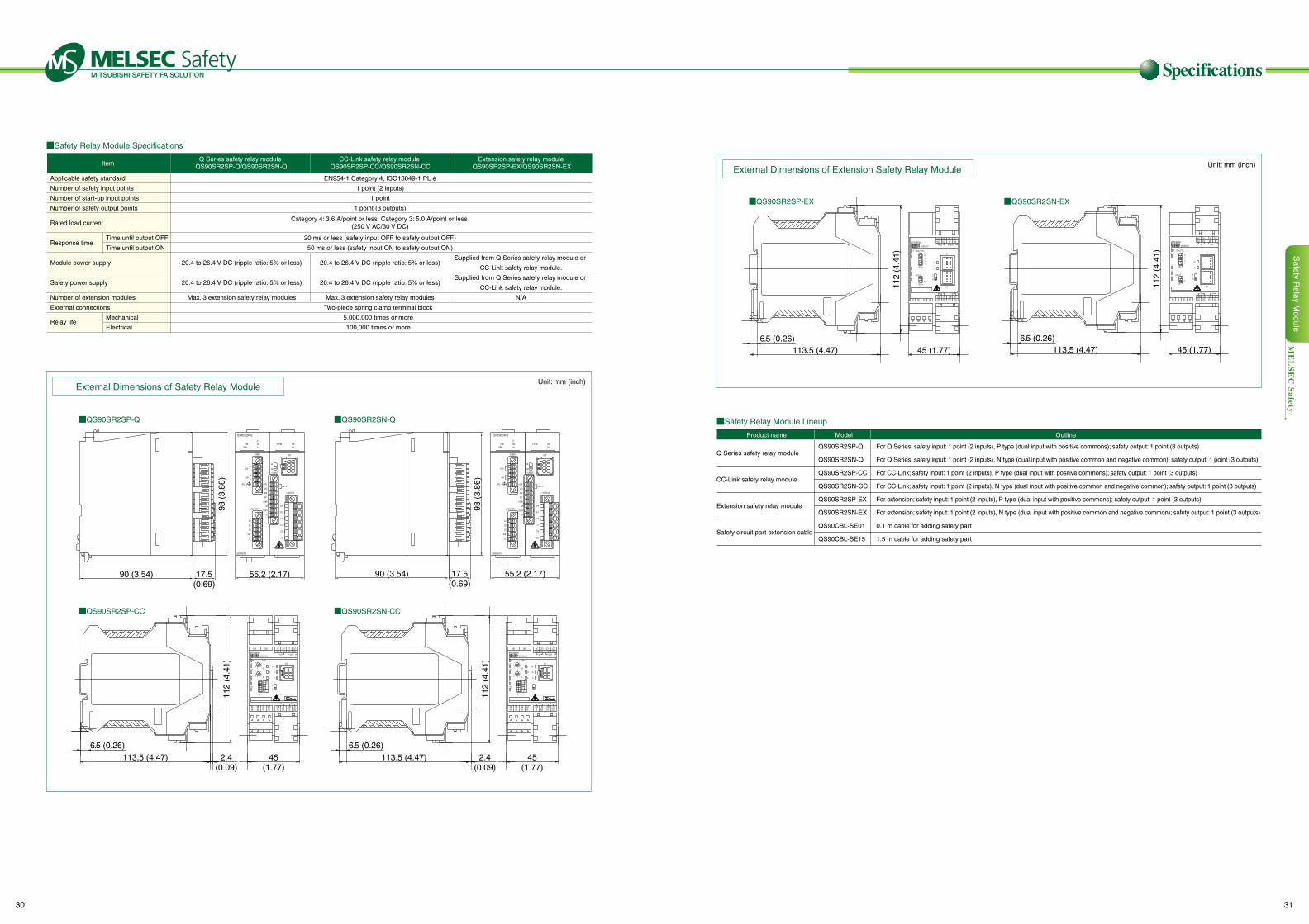
Safety Relay Module Specifications
Specifications
Safety Relay Module Lineup
ME
LS
EC
Safety
External Dimensions of Extension Safety Relay Module
External Dimensions of Safety Relay Module
QS90SR2SP-EX QS90SR2SN-EX
QS90SR2SP-Q QS90SR2SN-Q
QS90SR2SP-CC QS90SR2SN-CC
Unit: mm (inch)
Unit: mm (inch)ItemCC-Link safety relay module
QS90SR2SP-CC/QS90SR2SN-CCQ Series safety relay module
QS90SR2SP-Q/QS90SR2SN-QExtension safety relay module
QS90SR2SP-EX/QS90SR2SN-EX
Applicable safety standard
Number of safety input points
Number of start-up input points
Number of safety output points
Module power supply
Safety power supply
Number of extension modules
External connections
Rated load current
Response time
Relay life
Time until output OFF
Time until output ON
Mechanical
Electrical
EN954-1 Category 4, ISO13849-1 PL e
1 point (2 inputs)
1 point
1 point (3 outputs)
20 ms or less (safety input OFF to safety output OFF)
50 ms or less (safety input ON to safety output ON)
20.4 to 26.4 V DC (ripple ratio: 5% or less)
20.4 to 26.4 V DC (ripple ratio: 5% or less)
Max. 3 extension safety relay modules
Two-piece spring clamp terminal block
5,000,000 times or more
100,000 times or more
Category 4: 3.6 A/point or less, Category 3: 5.0 A/point or less(250 V AC/30 V DC)
20.4 to 26.4 V DC (ripple ratio: 5% or less)
20.4 to 26.4 V DC (ripple ratio: 5% or less)
Max. 3 extension safety relay modules
Supplied from Q Series safety relay module or
CC-Link safety relay module.
Supplied from Q Series safety relay module or
CC-Link safety relay module.
N/A
90 (3.54) 90 (3.54)17.5(0.69)
17.5(0.69)
55.2 (2.17)
113.5 (4.47)
113.5 (4.47) 113.5 (4.47)
113.5 (4.47)
112
(4.4
1)
112
(4.4
1)
112
(4.4
1)
112
(4.4
1)
2.4(0.09)
2.4(0.09)
45(1.77)
45 (1.77) 45 (1.77)
45(1.77)
6.5 (0.26)
55.2 (2.17)
98 (
3.86
)
98 (
3.86
)
Product name Model Outline
Q Series safety relay module
CC-Link safety relay module
Extension safety relay module
Safety circuit part extension cable
QS90SR2SP-Q
QS90SR2SN-Q
QS90SR2SP-CC
QS90SR2SN-CC
QS90SR2SP-EX
QS90SR2SN-EX
QS90CBL-SE01
QS90CBL-SE15
For Q Series; safety input: 1 point (2 inputs), P type (dual input with positive commons); safety output: 1 point (3 outputs)
For Q Series; safety input: 1 point (2 inputs), N type (dual input with positive common and negative common); safety output: 1 point (3 outputs)
For CC-Link; safety input: 1 point (2 inputs), P type (dual input with positive commons); safety output: 1 point (3 outputs)
For CC-Link; safety input: 1 point (2 inputs), N type (dual input with positive common and negative common); safety output: 1 point (3 outputs)
For extension; safety input: 1 point (2 inputs), P type (dual input with positive commons); safety output: 1 point (3 outputs)
For extension; safety input: 1 point (2 inputs), N type (dual input with positive common and negative common); safety output: 1 point (3 outputs)
0.1 m cable for adding safety part
1.5 m cable for adding safety part
6.5 (0.26)
6.5 (0.26) 6.5 (0.26)
Safety R
elay Module
30 31
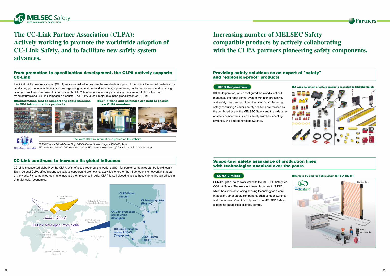
Partners
Providing safety solutions as an expert of "safety" and "explosion-proof" products
Supporting safety assurance of production lines with technologies acquired over the years
IDEC Corporation
SUNX Limited
Light cur tain
Safety components
Remote I/O unit for light curtain (SF-CL1T264T)
A wide selection of safety products essential to MELSEC Safety
From promotion to specification development, the CLPA actively supports CC-Link
The CC-Link Partner Association (CLPA): Actively working to promote the worldwide adoption of CC-Link Safety, and to facilitate new safety system advances.
Increasing number of MELSEC Safety compatible products by actively collaborating with the CLPA partners pioneering safety components.
6F Meiji Yasuda Seimei Ozone Bldg. 3-15-58 Ozone, Kita-ku, Nagoya 462-0825, JapanTEL: +81-52-919-1588 FAX: +81-52-916-8655 URL: http://www.cc-link.org/ E-mail: [email protected]
Conformance test to support the rapid increase in CC-Link compatible products.
Exhibitions and seminars are held to recruit new CLPA members.
The latest CC-Link information is posted on the website.
CC-Link continues to increase its global influence
The CC-Link Partner Association (CLPA) was established to promote the worldwide adoption of the CC-Link open field network. By conducting promotional activities, such as organizing trade shows and seminars, implementing conformance tests, and providing catalogs, brochures, and website information, the CLPA has been successfully increasing the number of CC-Link partner manufacturers and CC-Link compatible products. The CLPA takes a major role in the globalization of CC-Link.
IDEC Corporation, which configured the world's first cell
manufacturing robot control system with high productivity
and safety, has been providing the latest "manufacturing
safety consulting." Various safety solutions are realized by
the combined use of the MELSEC Safety and the wide array
of safety components, such as safety switches, enabling
switches, and emergency stop switches.
SUNX's light curtains work well with the MELSEC Safety via
CC-Link Safety. The excellent lineup is unique to SUNX,
which has been developing sensing technology as a core.
In addition, other safety components such as door switches
and the remote I/O unit flexibly link to the MELSEC Safety,
expanding capabilities of safety control.
CC-Link is supported globally by the CLPA. With offices throughout the world, support for partner companies can be found locally. Each regional CLPA office undertakes various support and promotional activities to further the influence of the network in that part of the world. For companies looking to increase their presence in Asia, CLPA is well placed to assist these efforts through offices in all major Asian economies.
CC-Link Partner Association
CC-Link: More open, more global More open, more globalCC-Link: More open, more global
CLPA-Korea (Seoul)
CC-Link promotion center China(Shanghai)
CC-Link promotion center ASEAN(Singapore)
CLPA-Headquarter (Nagoya)
CLPA-Taiwan (Taipei)
32 33
Others
Mitsubishi Programmable Controller Catalog
Related catalogs
Mitsubishi Electric's world class programmable
controller "MELSEC-Q Series" is introduced in
this catalog. It includes features of various
types of Q Series CPU and interface,
application examples, and detailed
specifications.
Open Field Network CC-Link Compatible Product Catalog
This catalog provides overview and
specifications of a worldwide open field
network (device level network) "CC-Link," a
sensor level network "CC-Link/LT," and a safety
network "CC-Link Safety" compatible products.
34 35
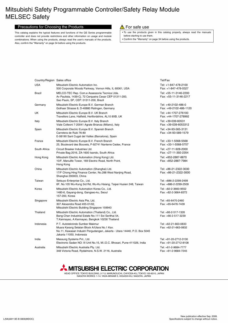
Mitsubishi Safety Programmable Controller/Safety Relay ModuleMELSEC Safety
This catalog explains the typical features and functions of the QS Series programmable controller and does not provide restrictions and other information on usage and module combinations. When using the products, always read the user's manuals of the products. Also, confirm the "Warranty" on page 34 before using the products.
To use the products given in this catalog properly, always read the manuals before starting to use them.Confirm the "Warranty" on page 34 before using the products.
L(NA)08113E-B 0809(MDOC)New publication effective Sep. 2008.
Specifications subject to change without notice.
HEAD OFFICE: TOKYO BUILDING, 2-7-3, MARUNOUCHI, CHIYODA-KU, TOKYO 100-8310, JAPANNAGOYA WORKS: 1-14, YADA-MINAMI 5, HIGASHI-KU, NAGOYA, JAPAN
Sales office
Mitsubishi Electric Automation Inc.500 Corporate Woods Parkway, Vernon Hills, IL 60061, USA
MELCO-TEC Rep. Com.e Assessoria Tecnica Ltda. Av Paulista, 1439-Cj. 72 Cerqueira Cesar CEP 01311-200,Sao Paulo, SP, CEP: 01311-200, Brazil
Mitsubishi Electric Europe B.V. German BranchGothaer Strasse 8, D-40880 Ratingen, Germany
Mitsubishi Electric Europe B.V. UK Branch Travellers Lane, Hatfield, Hertfordshire, AL10 8XB, UK
Mitsubishi Electric Europe B.V. Italy Branch Viale Colleoni 7-20041 Agrate Brianza (Milano), Italy
Mitsubishi Electric Europe B.V. Spanish BranchCarretera de Rubi 76-80E-08190 Sant Cugat del Valles (Barcelona), Spain
Mitsubishi Electric Europe B.V. French Branch25, Boulevard des Bouvets, F-92741 Nanterre Cedex, France
Circuit Breaker Industries Ltd.Private Bag 2016, ZA-1600 Isando, South Africa
Mitsubishi Electric Automation (Hong Kong) Ltd.10/F, Manulife Tower, 169 Electric Road, North Point, Hong Kong
Mitsubishi Electric Automation (Shanghai) Ltd.17/F Chong Hing Finance Center, No.288 West Nanjing Road,Shanghai 200003, China
Setsuyo Enterprise Co., Ltd.6F, No.105 Wu-Kung 3rd Rd, Wu-Ku Hsiang, Taipei Husien 248, Taiwan
Mitsubishi Electric Automation Korea Co., Ltd.1480-6, Gayang-dong, Gangseo-ku, Seoul 157-200, Korea
Mitsubishi Electric Asia Pte, Ltd.307 Alexandra Road #05-01/02, Mitsubishi Electric Building Singapore 159943
Mitsubishi Electric Automation (Thailand) Co., Ltd.Bang-Chan Industrial Estate No.111 Soi Serithai 54,T.Kannayao, A.Kannayao, Bangkok 10230 Thailand
P.T. Autoteknindo Sumber MakmurMuara Karang Selatan Block A/Utara No.1 Kav.No.11, Kawasan Industri Pergudangan, Jakarta - Utara 14440, P.O. Box 5045 Jakarta 11050, Indonesia
Messung Systems Pvt., Ltd.Electronic Sadan NO: III Unit No.15, M.I.D.C. Bhosari, Pune-411026, India
Mitsubishi Electric Australia Pty. Ltd.348 Victoria Road, Rydalmere, N.S.W. 2116, Australia
Country/Region
USA
Brazil
Germany
UK
Italy
Spain
France
South Africa
Hong Kong
China
Taiwan
Korea
Singapore
Thailand
Indonesia
India
Australia
Tel/Fax
Tel: +1-847-478-2100Fax: +1-847-478-0327
Tel: +55-11-3146-2200Fax: +55-11-3146-2217
Tel: +49-2102-486-0Fax: +49-2102-486-1120
Tel: +44-1707-276100Fax: +44-1707-278992
Tel: +39-039-60531Fax: +39-039-6053312
Tel: +34-93-565-3131Fax: +34-93-589-1579
Tel: +33-1-5568-5568Fax: +33-1-5568-5757
Tel: +27-11-928-2000Fax: +27-11-392-2354
Tel: +852-2887-8870Fax: +852-2887-7984
Tel: +86-21-2322-3030Fax: +86-21-2322-3000
Tel: +886-2-2299-2499Fax: +886-2-2299-2509
Tel: +82-2-3660-9552Fax: +82-2-3664-8372
Tel: +65-6470-2460Fax: +65-6476-7439
Tel: +66-2-517-1326Fax: +66-2-517-3239
Tel: +62-21-663-0833Fax: +62-21-663-0832
Tel: +91-20-2712-3130Fax: +91-20-2712-8108
Tel: +61-2-9684-7777Fax: +61-2-9684-7245