Embed Size (px)
Citation preview

Installation Sheets Manual 121Gas Combustion Combination Controls and Systems G
Technical Bulletin G77xIssue Date 0600
© 2000 Johnson Controls, Inc. 1Part No. 24-8143-588, Rev. A www.johnsoncontrols.comCode No. LIT-121250
Figure 1: G77x Intermittent Pilot Ignition Controls
The G77x family of controls is designed for indirect ignition of naturalgas, Liquefied Petroleum (LP) gas, manufactured gas, mixed gas, orLP gas-air mixtures.
Following are the application requirements of the G77x control.
• The G77x can be used on gas-fired equipment with a maximum firingrate of 117 kW (400,000 Btu/hr). Any application over 117 kW(400,000 Btu/hr) must have written approval in advance from theJohnson Controls Heating Products Engineering Department.
• All G77x applications must use a redundant gas valve system wherethe pilot and main valve seats are in series and opened in sequence forintermittent pilot ignition.
G77x Intermittent Pilot Ignition Controls
Description
ApplicationRequirements
2 GG77x Intermittent Pilot Ignition Controls Technical Bulletin
Table 1: SpecificationsIgnition Type Indirect
Ignition Source High voltage spark, capacitive discharge
High Voltage CableMaximum Length
1,220 mm (48 in.)
Flame Sense CableMaximum Length
1,220 mm (48 in.)
Flame Detection Means Flame rectification
Flame Detection Types Integral and remote
Minimum Flame Current 0.15 microampere
Flame Failure ResponseTime
0.8 second maximum1.5 seconds maximum (G776_G models only)
Spark Gap 2.5 mm (0.1 in.) nominal
Ignition Trials 1 or 3
Ignition Trial Times 8, 25, 50, 85, or 120 seconds*
Prepurge Times 0, 4, 15, or 30 seconds*
Interpurge 0, 15, or 30 seconds*
Automatic Recycle DelayPeriod
No recycle (G770, G777)5 minutes* (G775, G779)60 minutes* (G776, G778)
Power Requirements Control: 24 VAC, 60 Hz, nominalOperation Current: 0.2A nominal + valves
Contact Rating Main Valve: 2A continuous, 5A inrushPilot Valve: 2A continuous, 5A inrush
Ambient Operating andStorage Temperature
-40 to 70°C (-40 to 160°F) standard models-40 to 80°C (-40 to 175°F) high temperature models
Humidity 95% RH non-condensing
Wiring Connections Spark: Spike, Rajah, or 6.35 mm (1/4 in.) male spadeControl: 6.35 mm (1/4 in.) male spade
4.76 mm (3/16 in.) male spade optional
Types of Gas Natural, Liquefied Petroleum (LP), manufactured, mixed, orLP gas-air mixture
Packaging Bulk pack supplied to original equipment manufacturer(individual pack optional).
Bulk Pack Quantity 50
Bulk Pack Weight 15 kg (33 lb)
Agency Listing CSA (AGA/CGA) Certificate Number 164933-1073441Australian Gas Certificate Number 4524 (G770 models only)
Specification Standards ANSI Standard Z21.20, Z21.20a, Z21.20bCAN/CSA-C22.2 No.199
*Timings listed are for 60 Hz operation. Timings increase 20% for 50 Hz operation.
The performance specifications are nominal and conform to acceptable industrystandards. For application at conditions beyond these specifications, consult the localJohnson Controls office. Johnson Controls, Inc. shall not be liable for damages resultingfrom misapplication or misuse of its products.
Refer to the G77x Series Product Bulletin (LIT-4350430) for necessary information on operatingand performance specifications of this product.
GG77x Intermittent Pilot Ignition Controls Technical Bulletin 3
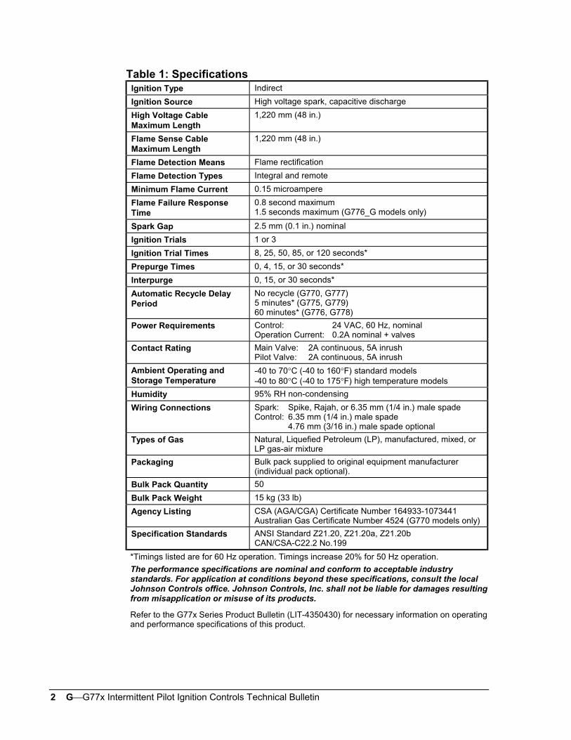
The following definitions describe operating conditions:
• Prepurge--Initial time delay between thermostat contact closure andtrial for ignition.
• Trial for Ignition--Period during which the pilot valve and spark areactivated, attempting to ignite gas at the pilot burner. The controlattempts to prove flame at the pilot burner within the trial-for-ignitiontime.
• Run--Pilot and main gas valves remain energized and spark is turnedoff after successful ignition.
• Shutoff--Pilot gas did not ignite within the trial-for-ignition time. Thecontrol de-energizes the spark circuit and pilot valve, and entersautomatic recycle period.
• Automatic Recycle--If shutoff occurs, the control delays for a specificrecycle delay period before beginning another trial for ignition (modelswith recycle only).
• Interpurge--Period between trials for ignition when both the gas valveand spark are deactivated to allow unburned gas to escape before thenext trial. Interpurge occurs between unsuccessful trials on a multi-trialcontrol or after a flameout (if the control has an interpurge).
• Ignition Lockout--Pilot gas did not ignite within the finaltrial-for-ignition time. Open thermostat contacts for 30 seconds, thenclose, to restart the sequence of operation. (Models with an optionalLight-Emitting Diode (LED) will flash the LED to indicate ignitionlockout.)
• Flameout--Loss of proven flame.
• Hard Lockout--The control detected a fault. Open thermostat contactsfor 30 seconds, then close to restart the sequence of operation. (Modelswith an optional LED will turn off the LED to indicate a hard lockout.)
OperatingModeDefinitions
4 GG77x Intermittent Pilot Ignition Controls Technical Bulletin
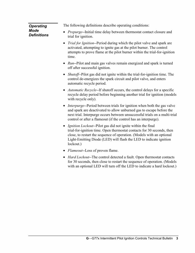
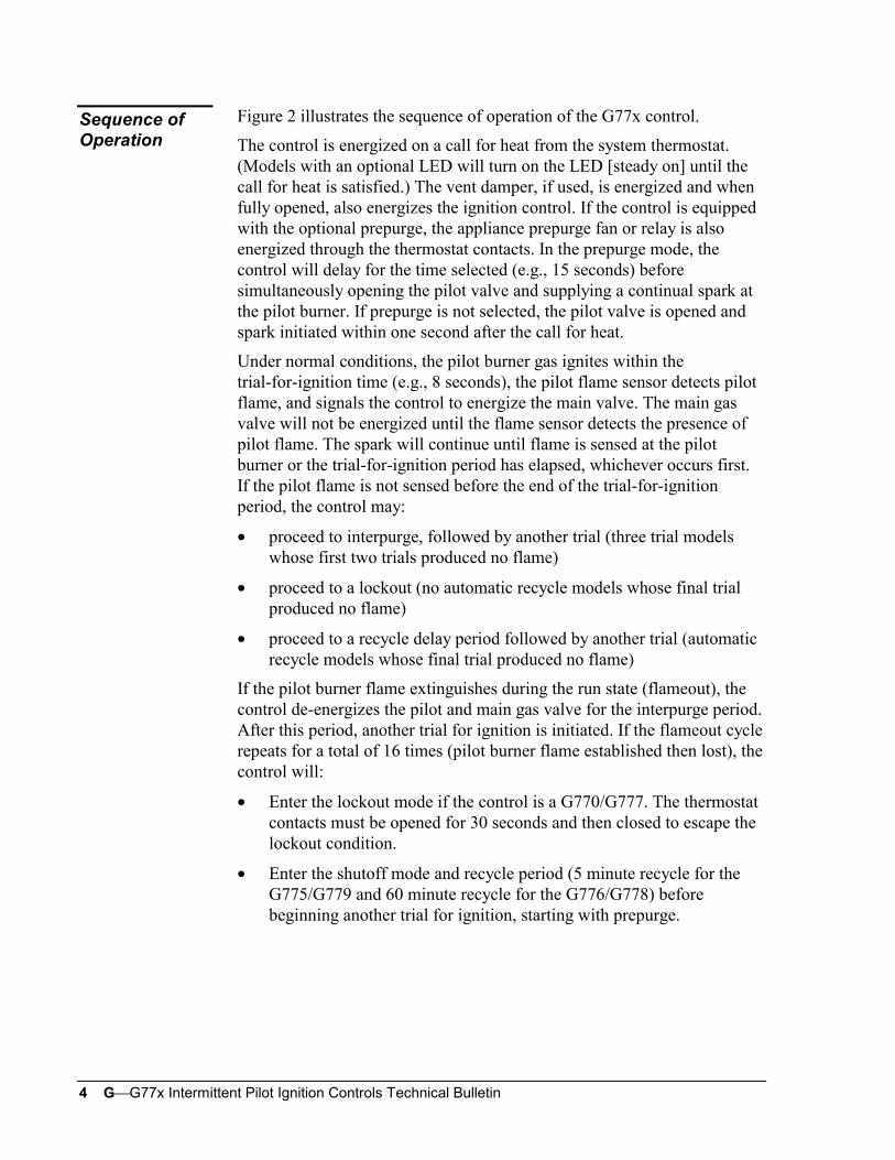
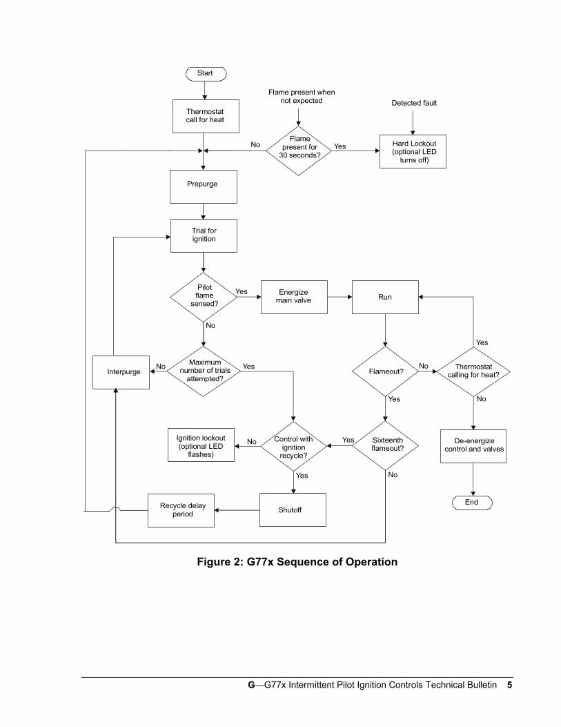
Figure 2 illustrates the sequence of operation of the G77x control.
The control is energized on a call for heat from the system thermostat.(Models with an optional LED will turn on the LED [steady on] until thecall for heat is satisfied.) The vent damper, if used, is energized and whenfully opened, also energizes the ignition control. If the control is equippedwith the optional prepurge, the appliance prepurge fan or relay is alsoenergized through the thermostat contacts. In the prepurge mode, thecontrol will delay for the time selected (e.g., 15 seconds) beforesimultaneously opening the pilot valve and supplying a continual spark atthe pilot burner. If prepurge is not selected, the pilot valve is opened andspark initiated within one second after the call for heat.
Under normal conditions, the pilot burner gas ignites within thetrial-for-ignition time (e.g., 8 seconds), the pilot flame sensor detects pilotflame, and signals the control to energize the main valve. The main gasvalve will not be energized until the flame sensor detects the presence ofpilot flame. The spark will continue until flame is sensed at the pilotburner or the trial-for-ignition period has elapsed, whichever occurs first.If the pilot flame is not sensed before the end of the trial-for-ignitionperiod, the control may:
• proceed to interpurge, followed by another trial (three trial modelswhose first two trials produced no flame)
• proceed to a lockout (no automatic recycle models whose final trialproduced no flame)
• proceed to a recycle delay period followed by another trial (automaticrecycle models whose final trial produced no flame)
If the pilot burner flame extinguishes during the run state (flameout), thecontrol de-energizes the pilot and main gas valve for the interpurge period.After this period, another trial for ignition is initiated. If the flameout cyclerepeats for a total of 16 times (pilot burner flame established then lost), thecontrol will:
• Enter the lockout mode if the control is a G770/G777. The thermostatcontacts must be opened for 30 seconds and then closed to escape thelockout condition.
• Enter the shutoff mode and recycle period (5 minute recycle for theG775/G779 and 60 minute recycle for the G776/G778) beforebeginning another trial for ignition, starting with prepurge.
Sequence ofOperation
GG77x Intermittent Pilot Ignition Controls Technical Bulletin 5
No Yes
Yes
NoMaximum
number of trialsattempted?
Yes
No
Yes No
Yes
No
Yes
De-energizecontrol and valves
No
Sixteenthflameout?
Control withignition
recycle?
Ignition lockout(optional LED
flashes)
Yes
No
Recycle delayperiod Shutoff
Flame present whennot expected
Hard Lockout(optional LED
turns off)
Start
Thermostatcall for heat
Prepurge
Flamepresent for
30 seconds?
Detected fault
Trial forignition
Pilotflame
sensed?
Energizemain valve Run
Thermostatcalling for heat?Flameout?Interpurge
End
Figure 2: G77x Sequence of Operation
6 GG77x Intermittent Pilot Ignition Controls Technical Bulletin
IMPORTANT: These instructions are intended as a guide forqualified personnel installing or servicingJohnson Controls ignition controls. Carefully followall instructions in this bulletin and all instructions onthe appliance. Limit repairs, adjustments, andservicing to the operations listed in this bulletin or onthe appliance.
! WARNING: Fire or Explosion Hazard. Avoid serious injury by
carefully following precautions in this bulletin andall instructions on the appliance. Limit repairs,adjustments, and servicing to the operations listed inthis bulletin or on the appliance.
! WARNING: Fire or Explosion Hazard. If the control is installed
in an area that is exposed to water (dripping,spraying, rain, etc.), it must be protected. If thecontrol has been exposed to water in any way, do notuse it.
! WARNING: Shock Hazard. Avoid electrical shock and
equipment damage. Disconnect electrical power andturn off gas before wiring control into circuit.
! CAUTION: Equipment Damage Hazard. Do not mount the
control where it will be exposed to direct infraredradiation from the main burner or to temperatures inexcess of the maximum product temperature rating.
Choose a location that provides the shortest, direct cable route to the sparkelectrode, pilot burner/igniter-sensor assembly. Easy access to theterminals is desired for wiring and servicing. The control may be mountedin any position. Mount the control on a grounded metal surface with metalscrews or bolts through the mounting holes provided in the enclosure.
Installation andWiring
Location andMounting
GG77x Intermittent Pilot Ignition Controls Technical Bulletin 7
! CAUTION: Equipment Damage Hazard. Connect the high
voltage cable to the spark transformer terminal andspark electrode (pilot burner assembly) beforeapplying power to the control. Be certain the groundwire is attached to the pilot burner and control groundterminal strip.
! CAUTION: Equipment Damage Hazard. Locate all limit and
operating controls in series with the thermostatterminal (THS 2) on the ignition control.
Check the voltage rating marked on the control and make sure it is suitedto the application. Use a National Electrical Code (NEC) Class 2transformer to provide 24 VAC under maximum load, including valves.A transformer having excessive primary impedance due to poor couplingwill affect the ignition potential.
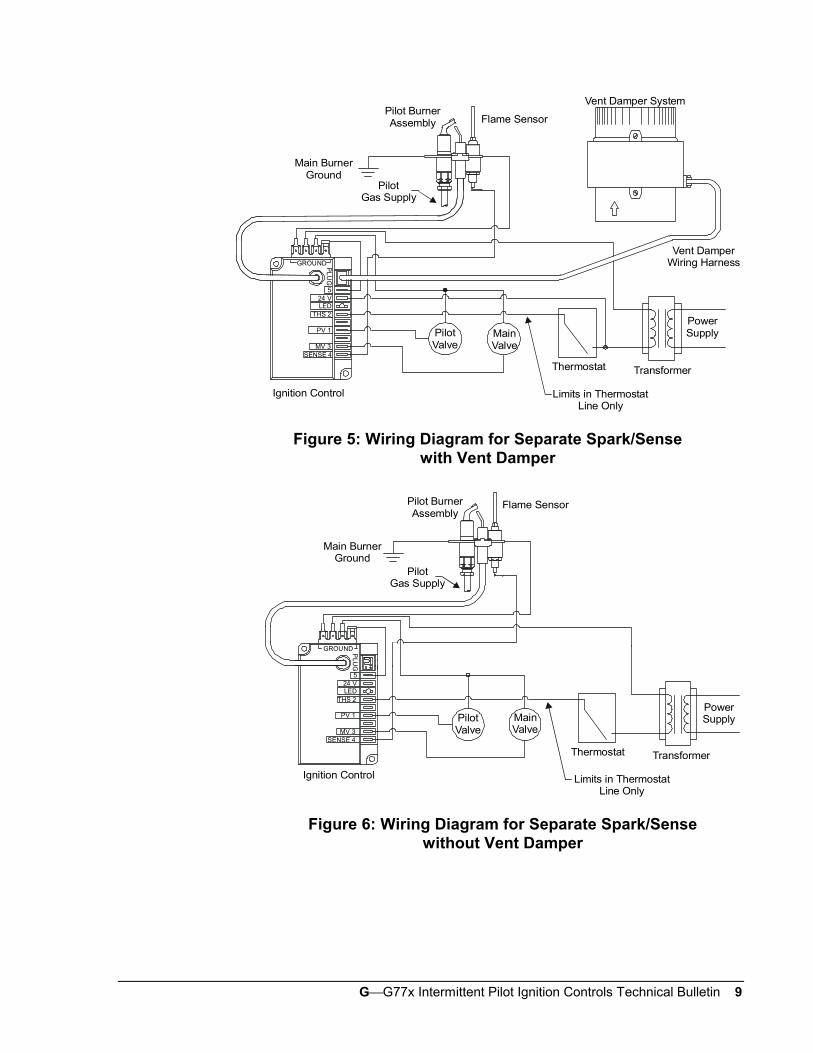
Refer to Figures 3 through 7 for wiring diagrams. All wiring should be inaccordance with the NEC and all other local codes and regulations. Thehigh voltage spark transformer cable must not be in continuous contactwith a metal surface. Use standoff insulators. Ensure that the flame sensorwire and the high voltage spark transformer cable are separated fromone another a minimum of 6.35 mm (1/4 in.) and not wrapped around anypipe, other wiring, or accessories.
ElectricalConnections

8 GG77x Intermittent Pilot Ignition Controls Technical Bulletin
Vent Damper System
Thermostat
PLU
G
GROUND
524 V
LED THS 2
PV 1
MV 3
Transformer
PowerSupply
Vent DamperWiring Harness
Ignition Control Limits in ThermostatLine Only
Pilot BurnerAssembly
IntegralIgniter/Sensor
Main BurnerGround
PilotGas Supply
PilotValve
MainValve
Figure 3: Wiring Diagram for Integral Spark/Sensewith Vent Damper
Thermostat
PLU
G
GROUND
524 V
LED THS 2
PV 1
MV 3
Transformer
Pilot BurnerAssembly Integral
Igniter/Sensor
Main BurnerGround
PilotGas Supply
Ignition Control Limits in ThermostatLine Only
PilotValve
MainValve
Figure 4: Wiring Diagram for Integral Spark/Sensewithout Vent Damper
GG77x Intermittent Pilot Ignition Controls Technical Bulletin 9
Flame Sensor
Thermostat
Vent Damper System
Transformer
PL
UG
5 24 V LED
THS 2
PV 1
MV 3SENSE 4
GROUND
Ignition Control Limits in ThermostatLine Only
PowerSupply
Vent DamperWiring Harness
Pilot BurnerAssembly
Main BurnerGround
PilotGas Supply
PilotValve
MainValve
Figure 5: Wiring Diagram for Separate Spark/Sensewith Vent Damper
Flame Sensor
Thermostat Transformer
PLU
G
5 24 V LED
THS 2
PV 1
MV 3SENSE 4
GROUND
Ignition Control
PilotValve
MainValve
Limits in ThermostatLine Only
PowerSupply
Main BurnerGround
PilotGas Supply
Pilot BurnerAssembly
Figure 6: Wiring Diagram for Separate Spark/Sensewithout Vent Damper
10 GG77x Intermittent Pilot Ignition Controls Technical Bulletin
Main BurnerGround
PilotGas Supply
Pilot BurnerAssembly
Flame Sensor
Limits in ThermostatLine Only
Thermostat Transformer
PowerSupplyMain
ValvePilotValve
RolloutSwitch
Ignition Control
SENSE 4MV 3
PV 1R1R.O. SWH
THS 2
5
GROUND
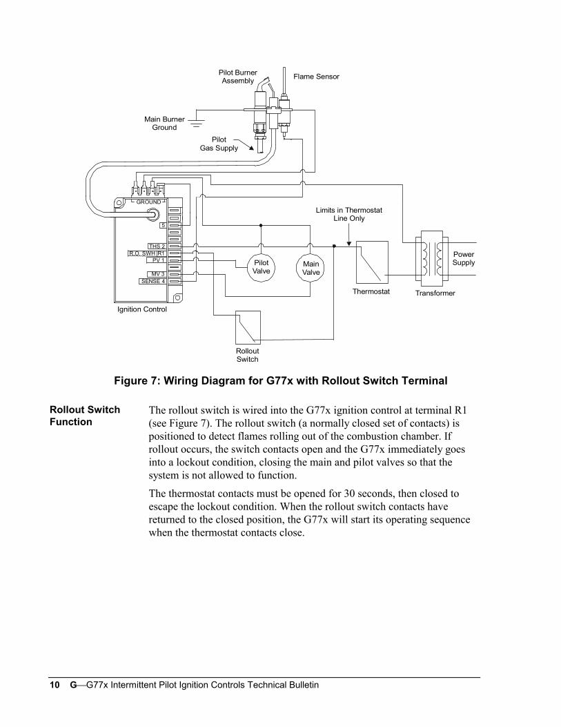
Figure 7: Wiring Diagram for G77x with Rollout Switch Terminal
The rollout switch is wired into the G77x ignition control at terminal R1(see Figure 7). The rollout switch (a normally closed set of contacts) ispositioned to detect flames rolling out of the combustion chamber. Ifrollout occurs, the switch contacts open and the G77x immediately goesinto a lockout condition, closing the main and pilot valves so that thesystem is not allowed to function.
The thermostat contacts must be opened for 30 seconds, then closed toescape the lockout condition. When the rollout switch contacts havereturned to the closed position, the G77x will start its operating sequencewhen the thermostat contacts close.
Rollout SwitchFunction
GG77x Intermittent Pilot Ignition Controls Technical Bulletin 11
Instructions for installing the spark electrode and sensor assembly aretypically provided by the appliance manufacturer. It is important to followthose instructions. If such information is not included, use the followingbasic instructions.
Location/Mounting
The pilot burner/igniter-sensor must be positioned for easy access andsecurely mounted to the main burner to ensure that the pilot burner flameremains properly positioned with respect to the main burner flame. Thepilot burner must be located such that the flame receives an ample supplyof air free from the products of combustion. The flame must not beexposed to draft conditions, the full force of main burner ignition, orfalling scale, which could otherwise impede ignition of main burner flame.
The pilot burner/igniter-sensor should be securely mounted to the mainburner with metal screws at a distance approximately 9.52 mm (3/8 in.)above and 6.35 mm (1/4 in.) away from center of the nearest main burnerport. Ensure that the main burner flames do not impinge on any part of thepilot burner.
Make sure that the flame sensor wire and the high voltage sparktransformer cable are separated from one another by a minimum distanceof 6.35 mm (1/4 in.) and not wrapped around any pipe, other wiring, ordevices.
PilotBurner/Igniter-Sensor
12 GG77x Intermittent Pilot Ignition Controls Technical Bulletin
! WARNING: Fire or Explosion Hazard. Avoid personal injury orproperty damage by making sure the controlfunctions properly and there are no gas leaks. Followthis checkout and startup procedure before leavingthe installation.
! WARNING: Fire or Explosion Hazard. Do not attempt to checkout this system by manually lighting the pilot. Thiscould energize the main valve.
Make sure all components function properly by performing the followingshutoff test.
1. With the gas and thermostat off, turn on power to the appliance.
2. Turn the thermostat to the highest setting and verify that the controlgoes through the operating sequence to a shutoff condition.
Note: The burner will not light because the gas is off.
3. Turn off the thermostat.
4. Turn on the gas and purge gas lines of all air.
5. Check for gas leaks on all pipe joints upstream of the gas valve with asoap solution.
6. Turn the thermostat to the highest setting and verify successfulignition and a normal run condition for at least three minutes. If theappliance fails to run, see the Service Checkout Procedures section.
7. Check for gas leaks on all pipe joints downstream of the gas valvewith a soap solution.
8. Turn the thermostat down for at least 30 seconds, and then back upagain. Verify successful ignition at least three times.
9. Return the thermostat to a normal temperature setting before leavingthe installation.
Checkout andStartupProcedure
GG77x Intermittent Pilot Ignition Controls Technical Bulletin 13
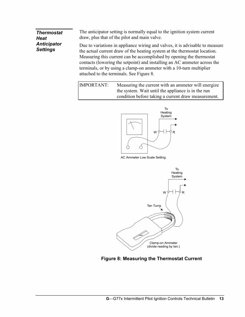
The anticipator setting is normally equal to the ignition system currentdraw, plus that of the pilot and main valve.
Due to variations in appliance wiring and valves, it is advisable to measurethe actual current draw of the heating system at the thermostat location.Measuring this current can be accomplished by opening the thermostatcontacts (lowering the setpoint) and installing an AC ammeter across theterminals, or by using a clamp-on ammeter with a 10-turn multiplierattached to the terminals. See Figure 8.
IMPORTANT: Measuring the current with an ammeter will energizethe system. Wait until the appliance is in the runcondition before taking a current draw measurement.
Ten Turns
W R
W R
AC Ammeter Low Scale Setting
ToHeatingSystem
ToHeatingSystem
Clamp-on Ammeter(divide reading by ten.)
Figure 8: Measuring the Thermostat Current
ThermostatHeatAnticipatorSettings
14 GG77x Intermittent Pilot Ignition Controls Technical Bulletin
! WARNING: Shock Hazard. Avoid electrical shock andequipment damage. Disconnect electrical power andturn off the gas before wiring the control into thecircuit.
! CAUTION: Equipment Damage Hazard. Label all wires priorto disconnection when servicing controls. Wiringerrors can cause improper and dangerous operation.Verify proper operation after servicing.
Perform the following procedure to replace the existing intermittent pilotignition control.
1. Shut off power to the appliance.
2. Turn off the gas at the manual shutoff valve adjacent to the appliance.
3. Label each wire with the correct terminal designation prior todisconnection.
4. Disconnect the power supply (transformer) and the thermostat leadwire at the ignition control.
5. Disconnect the sensing probe lead from Terminal 4 on the ignitioncontrol (separate spark/sense models only).
6. Disconnect the high voltage cable from the spark transformer.
7. Disconnect the Pilot Valve 1 and Main Valve 3 leads from the ignitioncontrol.
8. Disconnect any wires connected to the ground terminals.
9. Remove the screws holding the ignition control assembly in place.
10. Remove the ignition control and discard.
11. Using the same holes as the old ignition, mount the new control withmetal screws or bolts through the mounting holes in the enclosure.
12. Refer to the Installation and Wiring section for electrical connectionsand wiring information. The replacement G77x control has a Spiketransformer connection. Refer to the Modifying Existing Ignition Cablesection for connection to a Spike transformer.
13. Perform the Checkout and Startup Procedure before leaving theinstallation.
ReplacementProcedure
GG77x Intermittent Pilot Ignition Controls Technical Bulletin 15
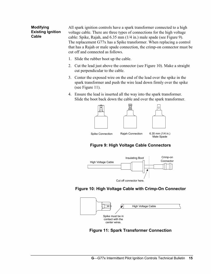
All spark ignition controls have a spark transformer connected to a highvoltage cable. There are three types of connections for the high voltagecable: Spike, Rajah, and 6.35 mm (1/4 in.) male spade (see Figure 9).The replacement G77x has a Spike transformer. When replacing a controlthat has a Rajah or male spade connection, the crimp-on connector must becut off and connected as follows.
1. Slide the rubber boot up the cable.
2. Cut the lead just above the connector (see Figure 10). Make a straightcut perpendicular to the cable.
3. Center the exposed wire on the end of the lead over the spike in thespark transformer and push the wire lead down firmly over the spike(see Figure 11).
4. Ensure the lead is inserted all the way into the spark transformer.Slide the boot back down the cable and over the spark transformer.
Spike Connection Rajah Connection 6.35 mm (1/4 in.)Male Spade
Figure 9: High Voltage Cable Connectors
High Voltage Cable
Insulating Boot Crimp-onConnector
Cut off connector here.
Figure 10: High Voltage Cable with Crimp-On Connector
High Voltage Cable
Spike must be incontact with the
center wires.
Figure 11: Spark Transformer Connection
ModifyingExisting IgnitionCable
16 GG77x Intermittent Pilot Ignition Controls Technical Bulletin
! WARNING: Fire or Explosion Hazard. Do not attempt servicingor troubleshooting when the LED is flashing (recyclemode or ignition lockout). The control automaticallyenergizes the system and could cause personal injuryor property damage.
If the system does not function properly, determine the cause using theprocedures in this section.
Before proceeding with troubleshooting the system, check the following:
• Are all mechanical and electrical connections tight?
• Is the system wired correctly?
• Is gas inlet pressure per manufacturer’s specifications?
• Is the system powered?
• Is the thermostat calling for heat?
• Is the optional LED flashing? If so, the control is in recycle mode or ithas entered an ignition lockout.
• Is the optional LED off? If so, the control is not receiving power, or ithas detected a fault. Faults are:
- flame present for more than 30 seconds at call for heat
- a defective control
There are three potential system failure conditions:
• No spark present, and system does not work.
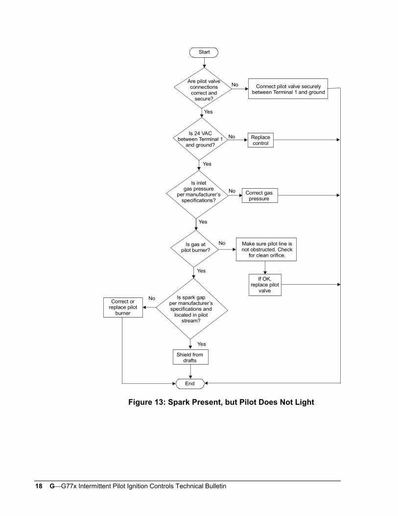
• Spark is present, but pilot does not light.
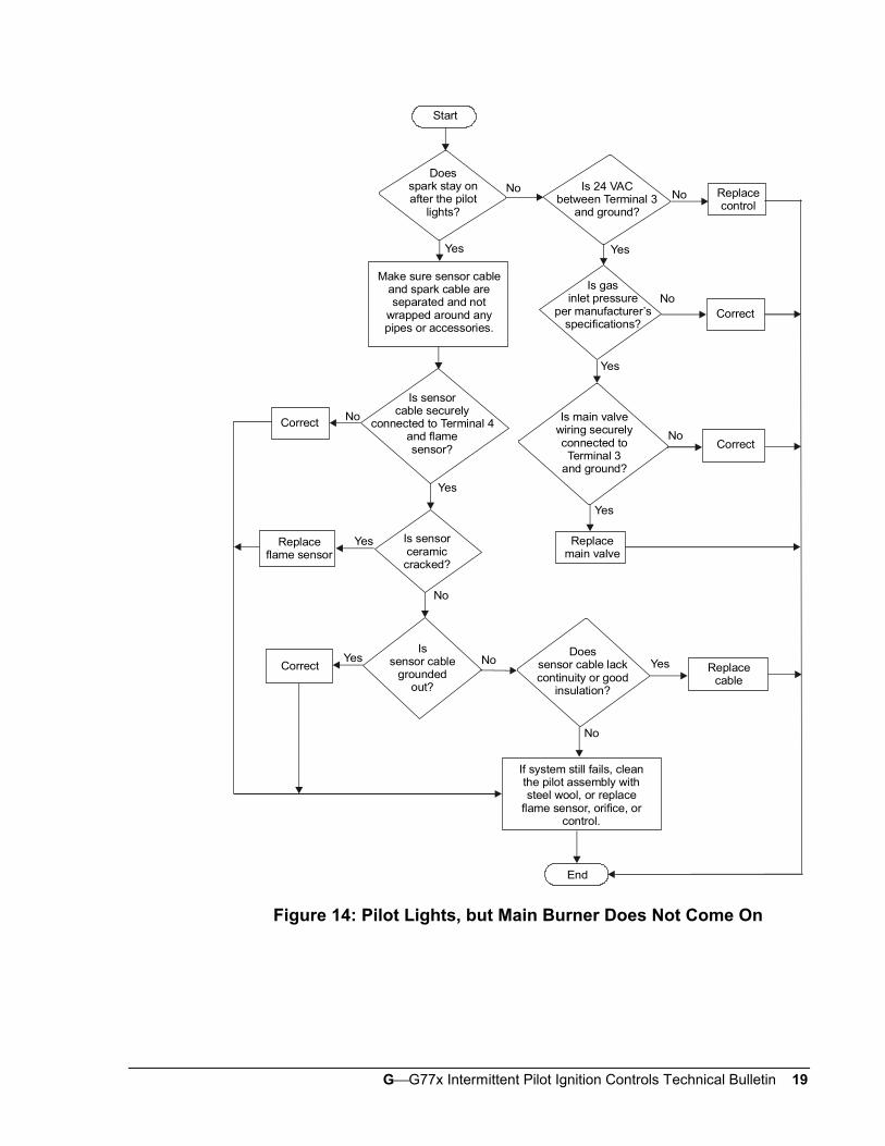
• Pilot lights, but main burner does not come on.
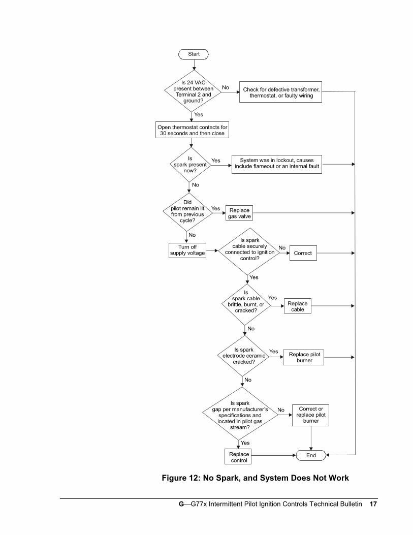
Determine the failure condition, then use the respective flowchart on thefollowing pages to troubleshoot the system. Perform the procedures in theCheckout and Startup Procedure section after any servicing.
ServiceCheckoutProcedures
PreliminaryChecks
FailureConditions andCorrectiveAction
GG77x Intermittent Pilot Ignition Controls Technical Bulletin 17
Start
Check for defective transformer,thermostat, or faulty wiring
Is 24 VACpresent betweenTerminal 2 and
ground?
Open thermostat contacts for30 seconds and then close
Yes
Isspark present
now?
Yes
No
System was in lockout, causesinclude flameout or an internal fault
Didpilot remain litfrom previous
cycle?
Replacegas valve
Turn offsupply voltage
Yes
No
No
Is sparkcable securely
connected to ignitioncontrol?
Is spark cable
brittle, burnt, orcracked?
Is sparkelectrode ceramic
cracked?
Is sparkgap per manufacturer’s
specifications andlocated in pilot gas
stream?
Replacecontrol
End
Yes
No
No
Correct orreplace pilot
burner
Yes Replace pilotburner
No
YesReplace
cable
Yes
NoCorrect
Figure 12: No Spark, and System Does Not Work
18 GG77x Intermittent Pilot Ignition Controls Technical Bulletin
Start
Connect pilot valve securelybetween Terminal 1 and ground
Are pilot valveconnectionscorrect and
secure?
Yes
Is 24 VACbetween Terminal 1
and ground?
No Replacecontrol
Yes
No
No
End
Yes
No
Yes
Yes
No
Is inletgas pressure
per manufacturer’sspecifications?
Correct gaspressure
Is gas atpilot burner?
Make sure pilot line isnot obstructed. Check
for clean orifice.
If OK,replace pilot
valveIs spark gap
per manufacturer’sspecifications and
located in pilotstream?
Correct orreplace pilot
burner
Shield fromdrafts
Figure 13: Spark Present, but Pilot Does Not Light
GG77x Intermittent Pilot Ignition Controls Technical Bulletin 19
Start
Doesspark stay onafter the pilot
lights?
Yes
No
No
No
End
YesNo
Yes
Yes
No
Is sensorcable securely
connected to Terminal 4and flamesensor?
Is sensorceramiccracked?
Is 24 VACbetween Terminal 3
and ground?
No Replacecontrol
Yes
Make sure sensor cableand spark cable areseparated and not
wrapped around anypipes or accessories.
Is gasinlet pressure
per manufacturer’sspecifications?
Correct
Correct
Yes
Is main valvewiring securelyconnected toTerminal 3
and ground?
CorrectNo
Yes
Replacemain valve
Replaceflame sensor
YesIs
sensor cablegrounded
out?
CorrectDoes
sensor cable lackcontinuity or good
insulation?
No
Replacecable
If system still fails, cleanthe pilot assembly withsteel wool, or replace
flame sensor, orifice, orcontrol.
Figure 14: Pilot Lights, but Main Burner Does Not Come On

20 GG77x Intermittent Pilot Ignition Controls Technical Bulletin
! CAUTION: Label all wires prior to disconnection when servicingcontrols. Wiring errors can cause improper anddangerous operation. Verify proper operation afterservicing.
The G77x controls are not field repairable. Do not attempt field repairs.Use only an exact or factory recommended replacement control.
All other accessories, such as flame sensors, electrode assemblies, pilotassemblies, and leads can be obtained through the original equipmentmanufacturer or a Johnson Controls distributor.
Repairs andReplacement
Controls Group www.johnsoncontrols.com507 E. Michigan Street FAN 121P.O. Box 423 Installation Sheets ManualMilwaukee, WI 53201 Printed in U.S.A.