Embed Size (px)
Citation preview
INSTALLATION INSTRUCTIONS
69-1954-01
®
Automatic Ignition SystemsANSI Z21.20
S8600B,C,H,M; S8610B,C,H,M; S8670D,E,J,K Intermittent Pilot Gas Ignition Control
APPLICATION
The 8600 family of ignition controls provide ignition sequence, flame monitoring and safety shutoff for intermittent pilot gas fired heating appliances. These controls provide flame sense and operating sequences suitable for the application.
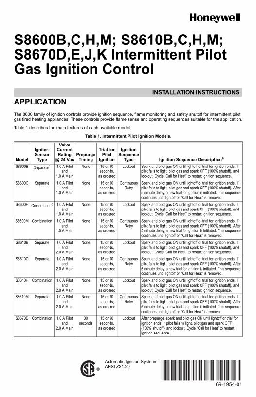
Table 1 describes the main features of each available model.
Table 1. Intermittent Pilot Ignition Models.
Model
Igniter-Sensor
Type
Valve Current Rating
@ 24 VacPrepurge
Timing
Trial for Pilot
Ignition
Ignition Sequence
Type Ignition Sequence Descriptiona
S8600B Separateb 1.0 A Pilotand
1.0 A Main
None 15 or 90 seconds,
as ordered
Lockout Spark and pilot gas ON until lightoff or trial for ignition ends. If pilot fails to light, pilot gas and spark OFF (100% shutoff), and lockout. Cycle “Call for Heat” to restart ignition sequence.
S8600C Separate 1.0 A Pilotand
1.0 A Main
None 15 or 90 seconds,
as ordered
ContinuousRetry
Spark and pilot gas ON until lightoff or trial for ignition ends. If pilot fails to light, pilot gas and spark OFF (100% shutoff). After 5 minute delay, a new trial for ignition is initiated. This sequence continues until lightoff or “Call for Heat” is removed.
S8600H Combinationc 1.0 A Pilotand
1.0 A Main
None 15 or 90 seconds,
as ordered
Lockout Spark and pilot gas ON until lightoff or trial for ignition ends. If pilot fails to light, pilot gas and spark OFF (100% shutoff), and lockout. Cycle “Call for Heat” to restart ignition sequence.
S8600M Combination 1.0 A Pilotand
1.0 A Main
None 15 or 90 seconds,
as ordered
ContinuousRetry
Spark and pilot gas ON until lightoff or trial for ignition ends. If pilot fails to light, pilot gas and spark OFF (100% shutoff). After 5 minute delay, a new trial for ignition is initiated. This sequence continues until lightoff or “Call for Heat” is removed.
S8610B Separate 1.0 A Pilotand
2.0 A Main
None 15 or 90 seconds,
as ordered
Lockout Spark and pilot gas ON until lightoff or trial for ignition ends. If pilot fails to light, pilot gas and spark OFF (100% shutoff), and lockout. Cycle “Call for Heat” to restart ignition sequence.
S8610C Separate 1.0 A Pilotand
2.0 A Main
None 15 or 90 seconds,
as ordered
ContinuousRetry
Spark and pilot gas ON until lightoff or trial for ignition ends. If pilot fails to light, pilot gas and spark OFF (100% shutoff). After 5 minute delay, a new trial for ignition is initiated. This sequence continues until lightoff or “Call for Heat” is removed.
S8610H Combination 1.0 A Pilotand
2.0 A Main
None 15 or 90 seconds,
as ordered
Lockout Spark and pilot gas ON until lightoff or trial for ignition ends. If pilot fails to light, pilot gas and spark OFF (100% shutoff), and lockout. Cycle “Call for Heat” to restart ignition sequence.
S8610M Separate 1.0 A Pilotand
2.0 A Main
None 15 or 90 seconds,
as ordered
ContinuousRetry
Spark and pilot gas ON until lightoff or trial for ignition ends. If pilot fails to light, pilot gas and spark OFF (100% shutoff). After 5 minute delay, a new trial for ignition is initiated. This sequence continues until lightoff or “Call for Heat” is removed.
S8670D Combination 1.0 A Pilotand
2.0 A Main
30seconds
15 or 90 seconds,
as ordered
Lockout After prepurge, spark and pilot gas ON until lightoff or trial for ignition ends. If pilot fails to light, pilot gas and spark OFF (100% shutoff), and lockout. Cycle “Call for Heat” to restart ignition sequence.
S8600B,C,H,M; S8610B,C,H,M; S8670D,E,J,K INTERMITTENT PILOT GAS IGNITION CONTROL
69-1954—01 2
All models provide:
• Natural or LP gas.• Pilot burner ignition using a high voltage spark.• Flame rectification circuit to monitor flame presence.• Monitoring of 24 Vac, pilot, and main gas valve.• LED indicator for flame presence/strength and system
status/errors.• Connections for flame reading via standard micro-
ammeter.• Optional: Alarm Output dry contacts (Lockout models
Only).
SPECIFICATIONS
Control Voltage: 24V (18-30 Vac) 50/60 HzCurrent Draw: 0.1 A plus valve load @ 24VacTrial for Ignition: 15 or 90 seconds (depends on model)Prepurge: See Table 1.Ignition Sequence: See Table 1.Retry Delay: 5 minutes (C, M, E, and K models only)Flame Failure Response Time: 2 seconds maximumLED: The green status LED provides system status, error
codes, and flame strength indication when in run mode.
Gas Control: Honeywell models VR8204 and VR8304Operating Temperature:
Minimum ambient temperature rating is -40°F (-40°C). Maximum ambient rating for S8600 used with 1.0A main valve is 175°F (79°C). Maximum ambient rating for S8610 and S8670 used with 2.0A main valve is 165°F (74°C).
Relative humidity: 0% to 95% noncondensing
PLANNING THE INSTALLATION
WARNINGFire or Explosion Hazard.Can cause severe injury, death or property damage.1. Plan the installation as outlined below.2. Plan for frequent maintenance as described in
the Maintenance section.
Intermittent pilot systems are used on a wide variety of central heating equipment and on heating appliances such as commercial cookers, agricultural equipment, industrial heating equipment and pool heaters. Some of these applications may make heavy demands on the controls, either because of frequent cycling, or because of moisture, corrosive chemicals, dust or excessive heat in the environment. In these situations, special steps may be required to prevent nuisance shutdowns and premature control failure. These applications require special Honeywell review; contact your Honeywell Sales Representative for assistance.
Review the following conditions that can apply to your specific installation and take the precautionary steps suggested.
Frequent CyclingThese controls are designed for use on appliances that typically cycle three to four times an hour only during the heating season. In year-round applications with greater cycling rates, the control can wear out more quickly; perform a monthly checkout.
Water or Steam CleaningIf the control gets wet, replace it. If the appliance is likely to be cleaned with water or steam, protect (cover) the controls and wiring from water or steam flow. Mount the controls high enough above the bottom of the cabinet so they do not get wet during normal cleaning procedures. Use a NEMA 4 enclosure for the ignition control.
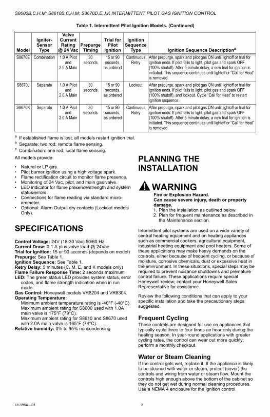
S8670E Combination 1.0 A Pilotand
2.0 A Main
30 seconds
15 or 90 seconds,
as ordered
ContinuousRetry
After prepurge, spark and pilot gas ON until lightoff or trial for ignition ends. If pilot fails to light, pilot gas and spark OFF (100% shutoff). After 5 minute delay, a new trial for ignition is initiated. This sequence continues until lightoff or “Call for Heat” is removed.
S8670J Separate 1.0 A Pilotand
2.0 A Main
30seconds
15 or 90 seconds,
as ordered
Lockout After prepurge, spark and pilot gas ON until lightoff or trial for ignition ends. If pilot fails to light, pilot gas and spark OFF (100% shutoff), and lockout. Cycle “Call for Heat” to restart ignition sequence.
S8670K Separate 1.0 A Pilot and
2.0 A Main
30seconds
15 or 90 seconds,
as ordered
ContinuousRetry
After prepurge, spark and pilot gas ON until lightoff or trial for ignition ends. If pilot fails to light, pilot gas and spark OFF (100% shutoff). After 5 minute delay, a new trial for ignition is initiated. This sequence continues until lightoff or “Call for Heat” is removed.
a If established flame is lost, all models restart ignition trial.b Separate: two rod; remote flame sensing.c Combination: one rod; local flame sensing.
Table 1. Intermittent Pilot Ignition Models. (Continued)
Model
Igniter-Sensor
Type
Valve Current Rating
@ 24 VacPrepurge
Timing
Trial for Pilot
Ignition
Ignition Sequence
Type Ignition Sequence Descriptiona
S8600B,C,H,M; S8610B,C,H,M; S8670D,E,J,K INTERMITTENT PILOT GAS IGNITION CONTROL
3 69-1954—01
High Humidity or Dripping WaterDripping water can cause the control to fail. Never install an appliance where water can drip on the controls.
In addition, high ambient humidity can damage the control.
If the appliance is in a humid atmosphere, make sure air circulation around the controls is adequate to prevent condensation. Also, regularly check out the system. A NEMA 4 enclosure is recommended for the ignition module.
Corrosive ChemicalsCorrosive chemicals can attack the module and gas control, eventually causing a failure. If chemicals are used for routine cleaning, make sure they do not reach the controls. Where chemicals are suspended in air, as in some industrial or agricultural applications, use a NEMA 4 enclosure for the ignition module.
Dust or Grease AccumulationHeavy accumulations of dust or grease can cause controls to malfunction. Where dust or grease can be a problem, provide covers for the module and the gas control to limit contamination. A NEMA 4 enclosure is recommended for the ignition module.
HeatExcessively high temperatures can damage controls. Make sure the maximum ambient temperature at the control does not exceed the rating of the control. If the appliance operates at very high temperatures, use insulation, shielding, and air circulation, as necessary, to protect the controls. Proper insulation or shielding should be provided by the appliance manufacturer; verify proper air circulation is maintained when the appliance is installed.
INSTALLATION
When Installing This Product…1. Read these instructions carefully. Failure to follow
them could damage the product or cause a hazard-ous condition.
2. Check the ratings given in these instructions to make sure the control is suitable for yourapplication.
3. Installer must be a trained, experienced service technician.
4. After installation is complete, check out operation as provided in these instructions.
WARNINGFire or Explosion Hazard.Can cause severe injury, death or property damage.1. The module can malfunction if it gets wet,
leading to accumulation of explosive gas.— Never install where water can flood, drip or
condense on the module.— Never try to use a module that has been wet—
replace it.2. Liquefied petroleum (LP) gas is heavier than air
and will not naturally vent upward.— Do not operate electric switches, lights, or
appliances until you are sure the appliance area is free of gas.
WARNINGElectrical Shock Hazard.Can cause severe injury, death or property damage.Disconnect power supply before beginning wiring or making wiring connections to prevent electrical shock or equipment damage.
CAUTION1. If a new gas control is to be installed, turn off
the gas supply before starting installation. Conduct a Gas Leak Test according to the gas control manufacturer instructions after the gas control is installed.
2. Wiring errors can cause improper appliance operation and dangerous conditions such as bypassing safety features.
CAUTIONEquipment Damage Hazard.Water can cause equipment damage or malfunction.If the module must be mounted near water or moisture, provide suitable waterproof enclosure.
Maintenance Requirements in Severe EnvironmentsRegular preventive maintenance is important in any application.
WARNINGFire or Explosion Hazard.May cause severe injury, death or property damage.Do not attempt to take the module apart or to clean it. Improper reassembly and cleaning may cause unreliable operation.
Maintenance frequency must be determined individually for each application. Some considerations are:
• Cycling frequency. Appliances that may cycle more than 20,000 times annually should be checked monthly.
• Intermittent use. Appliances that are used seasonally should be checked before shutdown and again before the next use.
• Consequence of unexpected shutdown. Where the cost of an unexpected shutdown would be high, the system should be checked more often.
• Dusty, wet, or corrosive environment. Since these environments can cause the modules to deteriorate more rapidly, the system should be checked more often.
Any module should be replaced if it does not perform properly on checkout or troubleshooting. In addition, replace any module if it is wet or looks like it has ever been wet. Protective enclosures as outlined under “Planning the Installation” are recommended regardless of checkout frequency.
LocationThe mounting location must provide:
— Good, clear access to the field wiring terminals.
S8600B,C,H,M; S8610B,C,H,M; S8670D,E,J,K INTERMITTENT PILOT GAS IGNITION CONTROL
69-1954—01 4
— Operating ambient temperatures between -40°F and 175°F (-40°C and 79°C); (165°F [74°C] for S8610 and S8670 models).
— Relative humidity below 95% noncondensing.— Protection from water, steam or corrosive chemicals
that are used to clean the appliance.— Protection from dripping water, such as from an
overfilled humidifier or from condensation.— Protection from dust or grease accumulation.
Mount the Ignition ModuleSelect a location close enough to the burner to allow a short (3 ft. [0.9 m] max.), direct cable route to the pilot burner. Ambient temperature at the module must be within the range listed under Operating Temperature, on page 2. The module must be protected from water, moisture, corrosive chemicals and excessive dust and grease.
Mount the module with the terminals down to protect them from dripping water and dust. As an alternative, it can also be mounted with the terminals on either side.
IMPORTANTDo not mount with terminals facing up.
Fig. 1. Incorrect Mounting (Model S8600M shown).
Fasten securely with four No. 6-32 machine or No. 8 sheet metal screws.
Mount the System ControlsMount any required controls, such as the gas control, spark igniter, flame sensor, thermostat, limit, and transformer according to manufacturer’s instructions.
Wire the System
CAUTIONEquipment Damage Hazard.Disconnect power supply before beginning wiring or making wiring connections to prevent electrical shock or equipment damage.
All wiring must comply with local codes and ordinances. See Fig. 2 and Table 4 for proper wiring connections.
IMPORTANT1. As shown in the wiring diagrams, a common
ground is required on:aThe pilot burner mounting bracket, andbThe GND(BURNER) terminal on the ignition
module. Failure to use the GND(BURNER) terminal may result in intermittent loss of spark and/or loss of flame current sensitivity.
2. Make sure the transformer has adequate VA. The ignition module requires at least 0.1 A at 24 Vac. Add the current draws of all other devices in the control circuit, including the pilot and main valves in the gas control, and multiply by 24 to determine the total VA requirement of these components. Add this total to 2.4 VA (for the igni-tion module). The result is the minimum trans-former VA rating. Use a Class II transformer if replacement is required.
CONNECT IGNITION CABLEUse Honeywell ignition cable or construct an ignition cable that conforms to suitable national standards such as Underwriters Laboratories Inc. See Table 2 and Table 3.
.
Cable must be no longer than 36 in. (0.9 m). Solid conductor cable recommended. To construct a cable, fit one end of ignition cable with 1/4 in. diameter Rajah connector receptacle and the other with a 1/4 in. female quick connect. Protect both ends with insulated boots.
NOTE: The cable must not run in continuous contact with a metal surface or spark voltage will be greatly reduced. Use ceramic or plastic standoff insulators as required. Resistive spark cable reduces spark voltage and may impact appliance performance.
To install:
(1) Connect one end of the cable to the male quick connect SPARK terminal on the igni-tion module.
(2) Connect the other end of the cable to the igniter or igniter-sensor stud on the pilot burner/igniter-sensor.
CONNECT IGNITION MODULE
NOTE: Refer to Fig. 2 and Table 4 for the location of each connection.
M29897
Table 2. Honeywell Pre-assembled Ignition Cables (UL Style 3257).
CABLEPART
NUMBER LENGTHMODULE
ENDPILOT
BURNER
394800-30 30 inches 1/4 inch quick connect, insulated
Rajah connector receptacle, 90 degree rubber boot
394801-30 30 inches 1/4 inch quick connect, insulated
Rajah connector receptacle, straight rubber boot
Table 3. Recommended Ignition Cable for Field Assembly.
CABLE TYPEVOLTAGE
RATING (rms)TEMPERATURE
RATING
UL Style 3217 10,000 302°F (150°C)
UL Style 3257 10,000 484°F (250°C)
S8600B,C,H,M; S8610B,C,H,M; S8670D,E,J,K INTERMITTENT PILOT GAS IGNITION CONTROL
5 69-1954—01
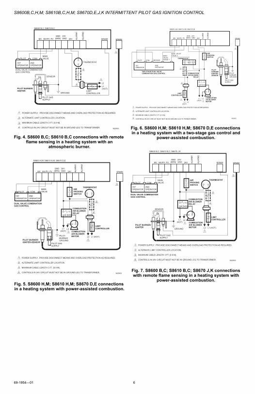
Connect remaining system components to the ignition module terminals as shown in the appropriate wiring diagram.• Fig. 3 is a basic circuit for the H and M models used in
heating systems with atmospheric burners.• Fig. 4 shows the basic circuit for the B and C models
with separate sensor and igniter in a heating system with atmospheric burners.
• Fig. 5—8 show typical circuits for power assisted combustion applications and two-stage gas control with power assisted combustion applications.
MAKE FLAME SENSE CONNECTION
For B, C, J, and K models:These models have remote flame sensing (two rod). Connect the flame sensor wire from the Pilot burner/igniter to the SENSE connector on the ignition module.
For H, M, D, and E models:These models have local flame sensing (single rod). The spark lead carries the flame signal.
CONNECT GAS CONTROLUse 18-gauge solid or stranded wire. Use 1/4 in. female quick connects for module connections. Connect to gas control terminals as shown in wiring diagrams, using terminals appropriate to the gas control.
GROUND CONTROL SYSTEMThe igniter, flame sensor and ignition module must share a common ground with the pilot burner. Use thermoplastic insulated wire with a minimum rating of 221°F (105°C) for the ground wire; asbestos insulation is not acceptable. If necessary, use a shield to protect the wire from radiant heat generated by the burner. Connect the ground wire as follows:
1. Fit one end of the ground wire with a female 1/4 in. quick-connect terminal and connect it to the male quick-connect BRN GND terminal on the ignition module.
2. Strip the other end of the wire and fasten it under the pilot burner bracket mounting screw. If neces-sary, use a shield to protect the ground wire from radiant heat.
3. The pilot burner serves as the common grounding area. If there is not good metal-to-metal contact between the pilot burner and ground, run a lead from the pilot burner to ground.
NOTE: Earth ground is not required.
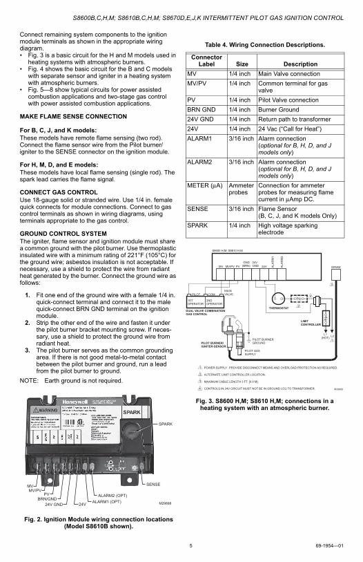
Fig. 2. Ignition Module wiring connection locations (Model S8610B shown).
Fig. 3. S8600 H,M; S8610 H,M; connections in a heating system with an atmospheric burner.
SPARK
MV
24V GND
MV/PV PV
BRN/GND
SENSE
ALARM2 (OPT) ALARM1 (OPT) 24V M29898
Table 4. Wiring Connection Descriptions.
ConnectorLabel Size Description
MV 1/4 inch Main Valve connection
MV/PV 1/4 inch Common terminal for gas valve
PV 1/4 inch Pilot Valve connection
BRN GND 1/4 inch Burner Ground
24V GND 1/4 inch Return path to transformer
24V 1/4 inch 24 Vac (“Call for Heat”)
ALARM1 3/16 inch Alarm connection (optional for B, H, D, and J models only)
ALARM2 3/16 inch Alarm connection (optional for B, H, D, and J models only)
METER (μA) Ammeter probes
Connection for ammeter probes for measuring flame current in μAmp DC.
SENSE 3/16 inch Flame Sensor (B, C, J, and K models Only)
SPARK 1/4 inch High voltage sparking electrode
THERMOSTAT
L1 (HOT) L2
1
LIMIT CONTROLLER
2
4 2ND OPERATOR
1ST OPERATOR
PILOT COM MAIN VALVE
DUAL VALVE COMBINATION GAS CONTROL
PILOT BURNER GROUND
PILOT GAS SUPPLY
PILOT BURNER/ IGNITER-SENSOR
3
POWER SUPPLY. PROVIDE DISCONNECT MEANS AND OVERLOAD PROTECTION AS REQUIRED. ALTERNATE LIMIT CONTROLLER LOCATION. MAXIMUM CABLE LENGTH 3 FT. [0.9 M]. CONTROLS IN 24V CIRCUIT MUST NOT BE IN GROUND LEG TO TRANSFORMER.
1
2
3
4 M29899
MV MV/PV PV GND
(BRN) 24V GND 24V SPARK
S8600 H,M; S8610 H,M
ALA
RM
1
ALA
RM
2
S8600B,C,H,M; S8610B,C,H,M; S8670D,E,J,K INTERMITTENT PILOT GAS IGNITION CONTROL
69-1954—01 6
Fig. 4. S8600 B,C; S8610 B,C connections with remote flame sensing in a heating system with an
atmospheric burner.
Fig. 5. S8600 H,M; S8610 H,M; S8670 D,E connections in a heating system with power-assisted combustion.
Fig. 6. S8600 H,M; S8610 H,M; S8670 D,E connections in a heating system with a two-stage gas control and
power-assisted combustion.
Fig. 7. S8600 B,C; S8610 B,C; S8670 J,K connections with remote flame sensing in a heating system with
power-assisted combustion.
POWER SUPPLY. PROVIDE DISCONNECT MEANS AND OVERLOAD PROTECTION AS REQUIRED. ALTERNATE LIMIT CONTROLLER LOCATION. MAXIMUM CABLE LENGTH 3 FT. [0.9 M]. CONTROLS IN 24V CIRCUIT MUST NOT BE IN GROUND LEG TO TRANSFORMER.
1
2
3
4 M29900
GROUND
PILOT GAS SUPPLY
2
4
3
SENSOR
L1 (HOT)
1
L2
LIMIT CONTROLLER
THERMOSTAT 2ND OPERATOR
1ST OPERATOR
PILOT COM MAIN VALVE
DUAL VALVE COMBINATION GAS CONTROL
MV MV/PV PV GND
(BRN) 24V GND 24V SPARK
S8600 B,C; S8610 B,C
SENSE ALA
RM
1
ALA
RM
2
PILOT BURNER/ IGNITER
THERMOSTAT
L1 (HOT) L2 1
LIMIT CONTROLLER
2
4
3
POWER SUPPLY. PROVIDE DISCONNECT MEANS AND OVERLOAD PROTECTION AS REQUIRED. ALTERNATE LIMIT CONTROLLER LOCATION. MAXIMUM CABLE LENGTH 3 FT. [0.9 M]. CONTROLS IN 24V CIRCUIT MUST NOT BE IN GROUND LEG TO TRANSFORMER.
1
2
3
4 M29901
AIR PROVING SWITCH
COMBUSTION AIR BLOWER RELAY
L1 (HOT)
L2 1 COMBUSTION
AIR BLOWER MOTOR
2ND OPERATOR
1ST OPERATOR
PILOT COM MAIN VALVE
DUAL VALVE COMBINATION GAS CONTROL
PILOT BURNER GROUND
PILOT GAS SUPPLY
PILOT BURNER/ IGNITER-SENSOR
MV MV/PV PV GND
(BRN) 24V GND 24V SPARK
S8600 H,M; S8610 H,M; S8670 D,E
ALA
RM
1
ALA
RM
2
PILOT BURNER GROUND
PILOT GAS SUPPLY
PILOT BURNER/ IGNITER- SENSOR
3
POWER SUPPLY. PROVIDE DISCONNECT MEANS AND OVERLOAD PROTECTION AS REQUIRED. ALTERNATE LIMIT CONTROLLER LOCATION. MAXIMUM CABLE LENGTH 3 FT. [0.9 M]. CONTROLS IN 24V CIRCUIT MUST NOT BE IN GROUND LEG TO TRANSFORMER.
1
2
3
4 M29902
AIR PROVING SWITCH
COMBUSTION AIR BLOWER
RELAY
L1 (HOT)
L2 1
COMBUSTION AIR BLOWER MOTOR
THERMOSTAT
L2 1
LIMIT CONTROLLER
L1 (HOT)
R W2 W1
2ND OPERATOR
1ST OPERATOR
COM
MAIN VALVE STAGE 1
TWO STAGE DUAL VALVE COMBINATION GAS CONTROL
PILOT GROUND
MAIN VALVE STAGE 2
4
2
MV MV/PV PV GND
(BRN) 24V GND 24V SPARK
S8600 H,M; S8610 H,M; S8670 D,E
ALA
RM
1
ALA
RM
2
THERMOSTAT
L1 (HOT) L2 1
LIMIT CONTROLLER
2
4
3
POWER SUPPLY. PROVIDE DISCONNECT MEANS AND OVERLOAD PROTECTION AS REQUIRED. ALTERNATE LIMIT CONTROLLER LOCATION. MAXIMUM CABLE LENGTH 3 FT. [0.9 M]. CONTROLS IN 24V CIRCUIT MUST NOT BE IN GROUND LEG TO TRANSFORMER.
1
2
3
4 M29903
AIR PROVING SWITCH
COMBUSTION AIR BLOWER RELAY
L1 (HOT)
L2 1 COMBUSTION
AIR BLOWER MOTOR
2ND OPERATOR
1ST OPERATOR
PILOT COM MAIN VALVE
DUAL VALVE COMBINATION GAS CONTROL
GROUND
PILOT GAS SUPPLY
MV MV/PV PV GND
(BRN) 24V GND 24V SPARK
S8600 B,C; S8610 B,C; S8670 J,K
SENSE ALA
RM
1
ALA
RM
2
SENSOR
PILOT BURNER/ IGNITER
S8600B,C,H,M; S8610B,C,H,M; S8670D,E,J,K INTERMITTENT PILOT GAS IGNITION CONTROL
7 69-1954—01
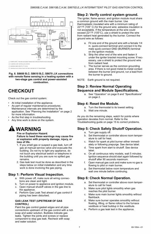
Fig. 8. S8600 B,C; S8610 B,C; S8670 J,K connections with remote flame sensing in a heating system with a
two-stage gas control and power-assisted combustion.
CHECKOUT
Check out the gas control system:
• At initial installation of the appliance.• As part of regular maintenance procedures.
Maintenance intervals are determined by the application. See “Planning the Installation” on page 2 for more information.
• As the first step in troubleshooting.• Any time work is done on the system.
WARNINGFire or Explosion Hazard.Failure to heed these warnings may cause fire or explosion with property damage, injury, or loss of life.1. If you smell gas or suspect a gas leak, turn off
gas at manual service valve and evacuate the building. Do not try to light any appliance, do not touch any electrical switch or telephone in the building until you are sure no spilled gas remains.
2. Gas leak test must be done as described in the steps below on initial installation and any time work is done involving the gas piping.
Step 1: Perform Visual Inspection.a. With power off, make sure all wiring connec-
tions are clean and tight.b. Turn on power to appliance and ignition module.c. Open manual shutoff valves in the gas line to
the appliance.d. Perform Gas Leak Test ahead of gas control if
piping has been disturbed.
GAS LEAK TEST (UPSTREAM OF GAS CONTROL)Paint the gas control gasket edges and all pipe connections upstream of the gas control with a rich soap and water solution. Bubbles indicate gas leaks. Tighten the joints and screws or replace component to stop gas leak. Recheck with soap and water solution.
Step 2: Verify control system ground.The igniter, flame sensor, and ignition module must share a common ground with the main burner. Use thermoplastic insulated wire with a minimum rating of 221°F (105° C) for the ground wire; asbestos insulation is not acceptable. If the temperature at the wire could exceed 221°F (105°C), use a shield to protect the wire from radiant heat generated by the burner. Connect the ground wire as follows:
a. Fit one end of the ground wire with a female 1/4 in. quick-connect terminal and connect it to the male quick-connect GND (BURNER) terminal on the ignition module.
b. Strip the other end of the wire and fasten it under the igniter bracket mounting screw. If nec-essary, use a shield to protect the ground wire from radiant heat.
c. The burner serves as the common grounding area. If there is not good metal-to-metal contact between the burner and ground, run a lead from the burner to ground.
NOTE: Earth ground is not required.
Step 3: Review Normal Operating Sequence and Module Specifications.
a. See “Operation” on page 8 and “Specifications” on page 2.
Step 4: Reset the Module.a. Turn the thermostat to its lowest setting.b. Wait one minute.
As you do the remaining steps, watch for points where operation deviates from normal. Refer to the Troubleshooting guide on page 15 to correct problems.
Step 5: Check Safety Shutoff Operation.a. Turn gas supply off.b. Set thermostat or controller above room temper-
ature to call for heat.c. Watch for spark at pilot burner either immedi-
ately or following prepurge. See device label.d. Time spark from start to shutoff. See device
label.e. On all continuous retry models, wait 5 minutes.
Ignition sequence should start again followed by shutoff after 90 seconds maximum.
f. Open manual gas cock and make sure no gas is flowing to pilot or main burner.
g. Set thermostat below room temperature and wait one minute before continuing.
Step 6: Check Normal Operation.a. Set thermostat or controller above room temper-
ature to call for heat.b. Make sure pilot lights smoothly when gas
reaches the pilot burner.c. Make sure main burner lights smoothly without
flashback.d. Make sure burner operates smoothly without
floating, lifting, or flame rollout to the furnace vestibule or heat buildup in the vestibule.
e. Perform a gas leak test in the appliance.
GROUND
PILOT GAS SUPPLY
3
POWER SUPPLY. PROVIDE DISCONNECT MEANS AND OVERLOAD PROTECTION AS REQUIRED. ALTERNATE LIMIT CONTROLLER LOCATION. MAXIMUM CABLE LENGTH 3 FT. [0.9 M]. CONTROLS IN 24V CIRCUIT MUST NOT BE IN GROUND LEG TO TRANSFORMER.
1
2
3
4 M29904
AIR PROVING SWITCH
COMBUSTION AIR BLOWER
RELAY
L1 (HOT)
L2 1
COMBUSTION AIR BLOWER MOTOR
THERMOSTAT
L2 1
LIMIT CONTROLLER
L1 (HOT)
R W2 W1
2ND OPERATOR
1ST OPERATOR
COM
MAIN VALVE STAGE 1
TWO STAGE DUAL VALVE COMBINATION GAS CONTROL
PILOT GROUND
MAIN VALVE STAGE 2
4
2
MV MV/PV PV GND
(BRN) 24V GND 24V SPARK
S8600 B,C; S8610 B,C; S8670 J,K
SENSE ALA
RM
1
ALA
RM
2
SENSOR
PILOT BURNER/ IGNITER
S8600B,C,H,M; S8610B,C,H,M; S8670D,E,J,K INTERMITTENT PILOT GAS IGNITION CONTROL
69-1954—01 8
GAS LEAK TEST (DOWNSTREAM OF GAS CONTROL)Paint the gas control gasket edges and all pipe connections downstream of the gas control, including the pilot tubing connections, with a rich soap and water solution. Bubbles indicate gas leaks. Tighten the joints and screws or replace component to stop gas leak. Recheck with soap and water solution.
f. Turn the thermostat or controller below the room temperature. Make sure the main burner and pilot flames go out.
OPERATION
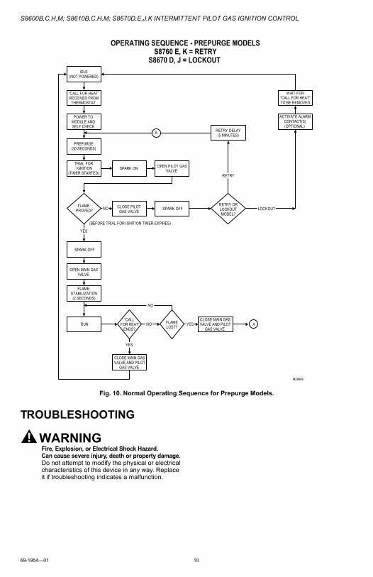
Module operation can be conveniently divided into two phases for the S8600 and S8610 and three phases for the S8670.
The phases are:
• Prepurge (S8670 models only)—See Fig. 10• Trial for ignition (all models)• Main burner operation (all models)
Fig. 9-10 summarize the normal operating sequences of all the models.
Prepurge (S8670 models Only)When an S8670 model is used in a fan-assisted combustion system, the combustion air blower starts on a call for heat. On proof of airflow, the air proving switch closes and energizes the S8670. When this model is used in an atmospheric system, the “Call for Heat” energizes the module.
In either case, the module first initiates a 30 second delay to allow system prepurge. After prepurge, the module starts the trial for pilot ignition sequence.
Trial for Pilot IgnitionOn a “Call for Heat” (and after prepurge on S8670 models), the module energizes the spark source and the pilot valve relay simultaneously. The pilot valve opens, allowing gas to flow to the pilot burner for the ignition trial time. The spark lights the pilot flame when pilot gas is present. A flame rectification circuit confirms the presence of the pilot flame, shuts off the spark source, and energizes the main valve relay.
The S8600 family uses a two-level pilot flame proving sequence. When a sufficient flame current is sensed, the spark is turned OFF. However, the pilot flame must generate a higher level of flame current to energize the main valve. This approach assures a stable pilot flame to support reliable burner lightoff. If the pilot flame is weak or unstable, the spark may turn back ON. However, the trial for pilot ignition will not exceed the stated ignition trial time
Main Burner OperationWhen the main valve opens, gas flows to the main burner where it is lit by the pilot flame. There is a short flame stabilization period as the main valve opens to allow the pilot flame to stabilize as the main gas lights. The system is now in the run mode with the presence of the pilot flame continuously monitored by the flame rectification circuit. If the pilot flame goes out, the control senses loss of pilot flame and shuts off both the pilot valve relay and the main valve relay. Flow of gas to pilot and main burners stops as the valves close.
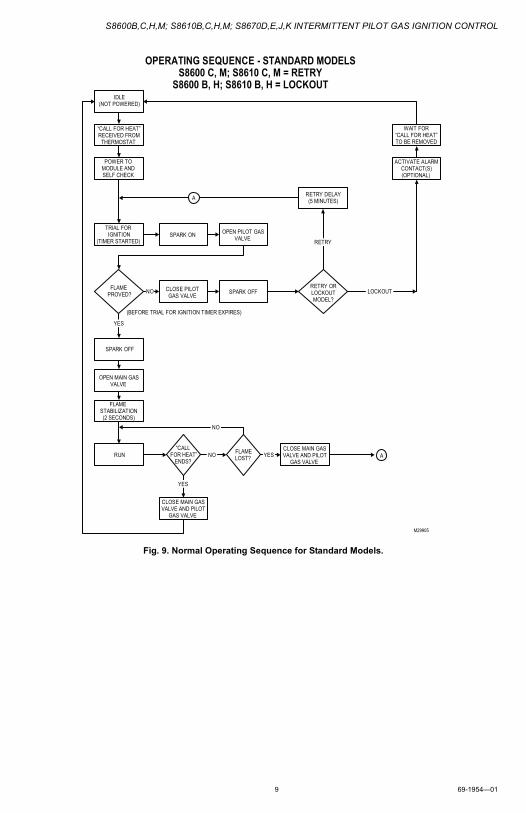
FAILED TRIAL FOR PILOT IGNITION
Lockout Models—S8600B,H; S8610B,H; S8670D,JLockout models provide a single trial for pilot ignition sequence. If the pilot flame is not lit and sensed before the end of the ignition trial time, the control shuts off the pilot valve (100% shutoff) and goes to lockout. The control remains in lockout until power to the control is cycled by the system thermostat or by removing and restoring system power.
Continuous Retry Models—S8600C,M; S8610C,M; S8670E,JContinuous retry models provide multiple trials for ignition. If the pilot is not lit or sensed before the end of the trial for ignition time, the control shuts off the spark and pilot gas (100% shutoff). There is a 5 minute delay before another ignition sequence is initiated. The pattern of ignition sequence followed by a 5 minute delay continues until the pilot lights and is proved or the “Call for Heat” ends. The 5 minute delay time can be bypassed by cycling the system thermostat or removing and restoring system power.
S8600B,C,H,M; S8610B,C,H,M; S8670D,E,J,K INTERMITTENT PILOT GAS IGNITION CONTROL
9 69-1954—01
Fig. 9. Normal Operating Sequence for Standard Models.
OPERATING SEQUENCE - STANDARD MODELS S8600 C, M; S8610 C, M = RETRY
S8600 B, H; S8610 B, H = LOCKOUT
“CALL FOR HEAT” RECEIVED FROM
THERMOSTAT
POWER TO MODULE AND SELF CHECK
IDLE (NOT POWERED)
RUN YES
WAIT FOR “CALL FOR HEAT” TO BE REMOVED
TRIAL FOR IGNITION
(TIMER STARTED) SPARK ON OPEN PILOT GAS
VALVE
FLAME PROVED?
FLAME STABILIZATION (2 SECONDS)
YES
NO
RETRY
RETRY OR LOCKOUT MODEL?
LOCKOUT
OPEN MAIN GAS VALVE
CLOSE MAIN GAS VALVE AND PILOT
GAS VALVE
ACTIVATE ALARM CONTACT(S) (OPTIONAL)
FLAME LOST?
NO
CLOSE PILOT GAS VALVE SPARK OFF
“CALL FOR HEAT”
ENDS?
YES
NO
RETRY DELAY (5 MINUTES)
SPARK OFF
A
(BEFORE TRIAL FOR IGNITION TIMER EXPIRES)
CLOSE MAIN GAS VALVE AND PILOT
GAS VALVE
M29905
A
S8600B,C,H,M; S8610B,C,H,M; S8670D,E,J,K INTERMITTENT PILOT GAS IGNITION CONTROL
69-1954—01 10
Fig. 10. Normal Operating Sequence for Prepurge Models.
TROUBLESHOOTING
WARNINGFire, Explosion, or Electrical Shock Hazard.Can cause severe injury, death or property damage.Do not attempt to modify the physical or electrical characteristics of this device in any way. Replace it if troubleshooting indicates a malfunction.
OPERATING SEQUENCE - PREPURGE MODELS S8760 E, K = RETRY
S8670 D, J = LOCKOUT
RUN YES
SPARK ON
FLAME PROVED?
YES
NO
RETRY
NO
SPARK OFF
YES
NO
SPARK OFF
A
(BEFORE TRIAL FOR IGNITION TIMER EXPIRES)
PREPURGE (30 SECONDS)
LOCKOUT
“CALL FOR HEAT” RECEIVED FROM
THERMOSTAT
POWER TO MODULE AND SELF CHECK
IDLE (NOT POWERED)
TRIAL FOR IGNITION
(TIMER STARTED) OPEN PILOT GAS
VALVE
RETRY OR LOCKOUT MODEL?
RETRY DELAY (5 MINUTES)
WAIT FOR “CALL FOR HEAT” TO BE REMOVED
ACTIVATE ALARM CONTACT(S) (OPTIONAL)
CLOSE PILOT GAS VALVE
FLAME STABILIZATION (2 SECONDS)
OPEN MAIN GAS VALVE
“CALL FOR HEAT”
ENDS?
CLOSE MAIN GAS VALVE AND PILOT
GAS VALVE
CLOSE MAIN GAS VALVE AND PILOT
GAS VALVE FLAME LOST?
M29906
A
S8600B,C,H,M; S8610B,C,H,M; S8670D,E,J,K INTERMITTENT PILOT GAS IGNITION CONTROL
11 69-1954—01
IMPORTANT1. The following service procedures are provided
as a general guide. Follow appliance manufac-turer’s service instructions if available.
2. Meter readings between the gas control and igni-tion control must be taken within the trial for igni-tion period. Once the ignition control shuts off, lockout models must be reset by setting the ther-mostat down for at least 30 seconds before con-tinuing. On retry models, wait for retry or reset at the thermostat.
3. If any component does not function properly, make sure it is correctly installed and wired before replacing it.
4. The ignition module cannot be repaired. If it mal-functions, it must be replaced.
5. Only trained, experienced service technicians should service intermittent pilot systems.
6. After troubleshooting, check out the system again to be sure it is operating normally.
General troubleshooting process is as follows:
1. Refer to “LED Status and Troubleshooting” on page 12 for LED status codes.
2. Perform the “Checkout” on page 7 as the first step in troubleshooting.
3. Check the troubleshooting guide (Fig. 14) to pin-point the cause of the problem.
4. If troubleshooting indicates an ignition problem, see Ignition System Checks below to isolate and correct the problem.
5. Following troubleshooting, perform the “Checkout” on page 7 again to be sure system is operating nor-mally.
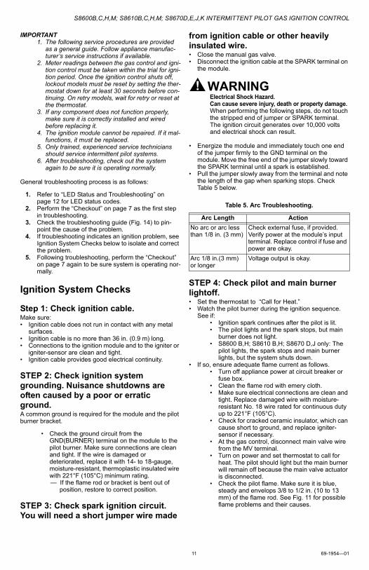
Ignition System Checks
Step 1: Check ignition cable.Make sure:• Ignition cable does not run in contact with any metal
surfaces.• Ignition cable is no more than 36 in. (0.9 m) long.• Connections to the ignition module and to the igniter or
igniter-sensor are clean and tight.• Ignition cable provides good electrical continuity.
STEP 2: Check ignition system grounding. Nuisance shutdowns are often caused by a poor or erratic ground.A common ground is required for the module and the pilot burner bracket.
• Check the ground circuit from the GND(BURNER) terminal on the module to the pilot burner. Make sure connections are clean and tight. If the wire is damaged or deteriorated, replace it with 14- to 18-gauge, moisture-resistant, thermoplastic insulated wire with 221°F (105°C) minimum rating.— If the flame rod or bracket is bent out of
position, restore to correct position.
STEP 3: Check spark ignition circuit. You will need a short jumper wire made
from ignition cable or other heavily insulated wire.• Close the manual gas valve.• Disconnect the ignition cable at the SPARK terminal on
the module.
WARNINGElectrical Shock Hazard.Can cause severe injury, death or property damage.When performing the following steps, do not touch the stripped end of jumper or SPARK terminal. The ignition circuit generates over 10,000 volts and electrical shock can result.
• Energize the module and immediately touch one end of the jumper firmly to the GND terminal on the module. Move the free end of the jumper slowly toward the SPARK terminal until a spark is established.
• Pull the jumper slowly away from the terminal and note the length of the gap when sparking stops. Check Table 5 below.
STEP 4: Check pilot and main burner lightoff.• Set the thermostat to “Call for Heat.”• Watch the pilot burner during the ignition sequence.
See if:• Ignition spark continues after the pilot is lit.• The pilot lights and the spark stops, but main
burner does not light.• S8600 B,H; S8610 B,H; S8670 D,J only: The
pilot lights, the spark stops and main burner lights, but the system shuts down.
• If so, ensure adequate flame current as follows.• Turn off appliance power at circuit breaker or
fuse box.• Clean the flame rod with emery cloth.• Make sure electrical connections are clean and
tight. Replace damaged wire with moisture-resistant No. 18 wire rated for continuous duty up to 221°F (105°C).
• Check for cracked ceramic insulator, which can cause short to ground, and replace igniter-sensor if necessary.
• At the gas control, disconnect main valve wire from the MV terminal.
• Turn on power and set thermostat to call for heat. The pilot should light but the main burner will remain off because the main valve actuator is disconnected.
• Check the pilot flame. Make sure it is blue, steady and envelops 3/8 to 1/2 in. (10 to 13 mm) of the flame rod. See Fig. 11 for possible flame problems and their causes.
Table 5. Arc Troubleshooting.
Arc Length Action
No arc or arc less than 1/8 in. (3 mm)
Check external fuse, if provided.Verify power at the module’s input terminal. Replace control if fuse and power are okay.
Arc 1/8 in.(3 mm) or longer
Voltage output is okay.
S8600B,C,H,M; S8610B,C,H,M; S8670D,E,J,K INTERMITTENT PILOT GAS IGNITION CONTROL
69-1954—01 12
• If necessary, adjust pilot flame by turning the pilot adjustment screw on the gas control clockwise to decrease or counterclockwise to increase pilot flame. Following adjustment, always replace pilot adjustment cover screw and tighten firmly to assure proper gas control operation.
• Set thermostat below room temperature to end call for heat.
Fig. 11. Examples of unsatisfactory pilot flames.
• Recheck ignition sequence as follows.• Reconnect main valve wire.• Set thermostat to call for heat.• Watch ignition sequence at burner.• If spark still doesn’t stop after pilot lights,
replace ignition control.• If main burner doesn’t light or if main burner
lights but system locks out, check the control, ground wire and gas control as described in “Troubleshooting” on page 10 and refer to the Troubleshooting Guide (Fig. 14).
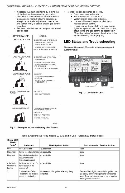
LED Status and Troubleshooting
The control has one LED used for flame sensing and system status:
Fig. 12. Location of LED.
LAZY YELLOW FLAME
WAVING BLUE FLAME
NOISY LIFTING BLOWING FLAME
HARD SHARP FLAME
SMALL BLUE FLAME CHECK FOR LACK OF GAS FROM:
• CLOGGED ORIFICE FILTER• CLOGGED PILOT FILTER
• LOW GAS SUPPLY PRESSURE
• PILOT ADJUSTMENT AT MINIMUM
CHECK FOR LACK OF AIR FROM:
• DIRTY ORIFICE
• DIRTY LINT SCREEN, IF USED
• DIRTY PRIMARY AIR OPENING, IF THERE IS ONE
• PILOT ADJUSTMENT AT MINIMUM
CHECK FOR:
• EXCESSIVE DRAFT AT PILOT LOCATION
• RECIRCULATING PRODUCTS OF COMBUSTION
CHECK FOR:
• HIGH GAS PRESSURE
THIS FLAME IS CHARACTERISTIC OF MANUFACTURED GAS
CHECK FOR:
• HIGH GAS PRESSURE
• ORIFICE TOO SMALL
M2233B
APPEARANCE CAUSE
STATUS LED M29907
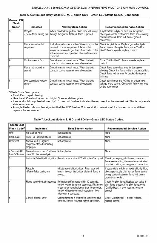
Table 6. Continuous Retry Models C, M, E, and K Only—Green LED Status Codes.
Green LEDFlash Codea Indicates Next System Action Recommended Service Action
OFF No “Call for Heat” Not applicable None
Flash Fast Power up - internal check Not applicable None
Heartbeat Normal startup - ignition sequence started (including prepurge)
Not applicable None
4 Seconds ON then “x” flashes
Device in run mode. “x” = flame current to the nearest μA.
Not applicable None
2 5 minute Retry Delay - Pilot flame not detected during trial for ignition
Initiate new trial for ignition after retry delay completed.
If system fails to light on next trial for ignition check gas supply, pilot burner, spark and flame sense wiring, flame rod contaminated or out of position, burner ground connection.
S8600B,C,H,M; S8610B,C,H,M; S8670D,E,J,K INTERMITTENT PILOT GAS IGNITION CONTROL
13 69-1954—01
3 Recycle - Flame failed during run
Initiate new trial for ignition. Flash code will remain through the ignition trial until flame is proved.
If system fails to light on next trial for ignition, check gas supply, pilot burner, flame sense wiring, contamination of flame rod, burner ground connection.
4 Flame sensed out of sequence
If situation self corrects within 10 seconds, control returns to normal sequence. If flame out of sequence remains longer than 10 seconds, control will resume normal operation 1 hour after error is corrected.
Check for pilot flame. Replace gas valve if pilot flame present. If no pilot flame, cycle “Call for Heat.” If error repeats, replace control.
6 Control Internal Error Control remains in wait mode. When the fault corrects, control resumes normal operation.
Cycle “Call for Heat”. If error repeats, replace control.
7 Flame rod shorted to ground
Control remains in wait mode. When the fault corrects, control resumes normal operation.
Check flame sense lead wire for damage or shorting. Check that flame rod is in proper position. Check flame rod ceramic for cracks, damage or tracking.
8 Low secondary voltage supply
Control remains in wait mode. When the fault corrects, control resumes normal operation.
Check transformer and AC line for proper input voltage to the control. Check with full system load on the transformer.
a Flash Code Descriptions:- Flash Fast: rapid blinking.- Heartbeat: Constant ½ second bright, ½ second dim cycles.- 4 second solid on pulse followed by “x” 1 second flashes indicates flame current to the nearest μA. This is only avail-
able in run mode.- A single flash code number signifies that the LED flashes X times at 2Hz, remains off for two seconds, and then
repeats the sequence.
Table 7. Lockout Models B, H D, and J Only—Green LED Status Codes.
Green LEDFlash Codea Indicates Next System Action Recommended Service Action
OFF No “Call for Heat” Not applicable None
Flash Fast Power up - internal check Not applicable None
Heartbeat Normal startup - ignition sequence started (including prepurge)
Not applicable None
4 Seconds ON then “x” flashes
Device in run mode. “x” = flame current to the nearest μA.
Not applicable None
2 Lockout - Failed trial for ignition Remain in lockout until “Call for Heat” is cycled. Check gas supply, pilot burner, spark and flame sense wiring, flame rod contaminated or out of position, burner ground connection.
3 Recycle - Flame failed during run
Initiate new trial for ignition. Flash code will remain through the ignition trial until flame is proved.
If system fails to light on next trial for ignition, check gas supply, pilot burner, flame sense wiring, contamination of flame rod, burner ground connection.
4 Flame sensed out of sequence If situation self corrects within 10 seconds, control returns to normal sequence. If flame out of sequence remains longer than 10 seconds, control will resume normal operation 1 hour after error is corrected.
Check for pilot flame. Replace gas valve if pilot flame present. If no pilot flame, cycle “Call for Heat.” If error repeats, replace control.
6 Control Internal Error Control remains in wait mode. When the fault corrects, control resumes normal operation.
Cycle “Call for Heat”. If error repeats, replace control.
Table 6. Continuous Retry Models C, M, E, and K Only—Green LED Status Codes. (Continued)
Green LEDFlash Codea Indicates Next System Action Recommended Service Action
S8600B,C,H,M; S8610B,C,H,M; S8670D,E,J,K INTERMITTENT PILOT GAS IGNITION CONTROL
69-1954—01 14
a Flash Code Descriptions:- Flash Fast: rapid blinking.- Heartbeat: Constant ½ second bright, ½ second dim cycles.- 4 second solid on pulse followed by “x” 1 second flashes indicates flame current to the nearest μA. This is only
available in run mode.- A single flash code number signifies that the LED flashes X times at 2Hz, remains off for two seconds, and then
repeats the sequence.
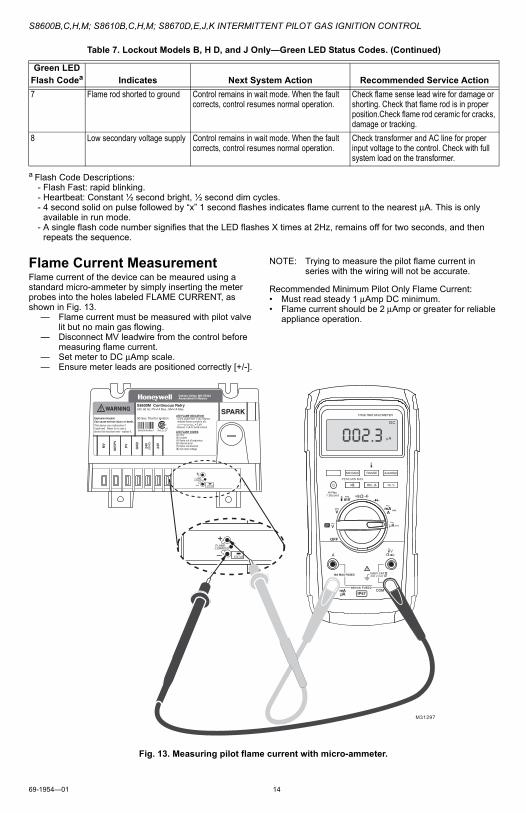
Flame Current MeasurementFlame current of the device can be meaured using a standard micro-ammeter by simply inserting the meter probes into the holes labeled FLAME CURRENT, as shown in Fig. 13.
— Flame current must be measured with pilot valve lit but no main gas flowing.
— Disconnect MV leadwire from the control before measuring flame current.
— Set meter to DC μAmp scale.— Ensure meter leads are positioned correctly [+/-].
NOTE: Trying to measure the pilot flame current in series with the wiring will not be accurate.
Recommended Minimum Pilot Only Flame Current:• Must read steady 1 μAmp DC minimum.• Flame current should be 2 μAmp or greater for reliable
appliance operation.
Fig. 13. Measuring pilot flame current with micro-ammeter.
7 Flame rod shorted to ground Control remains in wait mode. When the fault corrects, control resumes normal operation.
Check flame sense lead wire for damage or shorting. Check that flame rod is in proper position.Check flame rod ceramic for cracks, damage or tracking.
8 Low secondary voltage supply Control remains in wait mode. When the fault corrects, control resumes normal operation.
Check transformer and AC line for proper input voltage to the control. Check with full system load on the transformer.
Table 7. Lockout Models B, H D, and J Only—Green LED Status Codes. (Continued)
Green LEDFlash Codea Indicates Next System Action Recommended Service Action
+
–FLAMECURRENT
+
–FLAMECURRENT
M31297
002.3DC
µA
50043739-003 Rev. A
S8600M Continuous Retry24V, 60 Hz; PV=1A Max.; MV=1A Max.
90 Sec. Trial for Ignition
WARNING!Explosion Hazard.Can cause serious injury or death.This device can malfunction ifit gets wet. Never try to use adevice that has been wet - replace it.
MV
MV
/PV
PV
GN
D
24V
(GN
D)
24V
SPARK
Golden Valley, MN 55422Assembled in Mexico
®
C USANSI Z21.20
LED FLAME INDICATION:- 4 sec. pulse then 1 sec. flashes indicate flame current in uA: = 3 uA- Ensure 1 uA to avoid lockout
LED FLASH CODES:(2) retry(3) recycle(4) flame out of sequence(6) internal error(7) flame rod shorted(8) low input voltage
STATUS
STATUS
S8600B,C,H,M; S8610B,C,H,M; S8670D,E,J,K INTERMITTENT PILOT GAS IGNITION CONTROL
15 69-1954—01
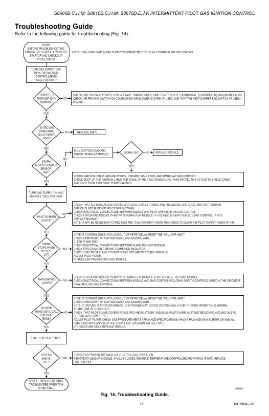
Troubleshooting GuideRefer to the following guide for troubleshooting (Fig. 14).
Fig. 14. Troubleshooting Guide.
POWER TOMODULE? (24 V
NOMINAL)
PILOT BURNERLIGHTS?
SPARKSTOPS WHEN
PILOT IS LIT?
MAIN BURNER LIGHTS?
SYSTEMRUNS UNTIL “CALL
FOR HEAT”ENDS?
“CALL FOR HEAT” ENDS
SYSTEMSHUTSOFF?
REPEAT PROCEDURE UNTIL TROUBLE FREE OPERATION
IS OBTAINED.
NO
CHECK IGNITION CABLE, GROUND WIRING, CERAMIC INSULATOR, AND SPARK GAP AND CORRECT. CHECK BOOT OF THE IGNITION CABLE FOR SIGNS OF MELTING OR BUCKLING. TAKE PROTECTIVE ACTION TO SHIELD CABLE AND BOOT FROM EXCESSIVE TEMPERATURES.
CHECK THAT ALL MANUAL GAS VALVES ARE OPEN, SUPPLY TUBING AND PRESSURES ARE GOOD, AND PILOT BURNER ORIFICE IS NOT BLOCKED (PILOT GAS FLOWING). CHECK ELECTRICAL CONNECTIONS BETWEEN MODULE AND PILOT OPERATOR ON GAS CONTROL. CHECK FOR 24 VAC ACROSS PV-MV/PV TERMINALS ON MODULE. IF VOLTAGE IS OKAY, REPLACE GAS CONTROL. IF NOT, REPLACE MODULE.NOTE: IT MAY BE NECESSARY TO RECYCLE THE “CALL FOR HEAT” MORE THAN ONCE TO CLEAR THE PILOT SUPPLY TUBES OF AIR.
CHECK FOR 24 VAC ACROSS PV-MV/PV TERMINALS ON MODULE. IF NO VOLTAGE, REPLACE MODULE.CHECK ELECTRICAL CONNECTIONS BETWEEN MODULE AND GAS CONTROL INCLUDING SAFETY CONTROLS WIRED IN THE CIRCUIT. IF OKAY, REPLACE GAS CONTROL.
CHECK FOR PROPER THERMOSTAT (CONTROLLER) OPERATION.REMOVE MV LEAD AT MODULE. IF VALVE CLOSES, RECHECK TEMPERATURE CONTROLLER AND WIRING. IF NOT, REPLACE GAS CONTROL.
SPARK OK?
NO
NO
NO
NO
NO
NO
NO
YES
YES
YES
YES
YES
YES
YES
YES
REPLACE S8670NO
REPLACE MODULE
YES
NOTE: “CALL FOR HEAT” 24 VAC SUPPLY IS CONNECTED TO THE 24 V TERMINAL ON THE CONTROL.
STARTBEFORE TROUBLESHOOTING,
FAMILIARIZE YOURSELF WITH THESTARTUP AND CHECKOUT
PROCEDURES.
TURN GAS SUPPLY OFF.TURN THERMOSTAT (CONTROLLER)TO “CALL FOR HEAT.”
CHECK LINE VOLTAGE POWER, LOW VOLTAGE TRANSFORMER, LIMIT CONTROLLER, THERMOSTAT (CONTROLLER), AND WIRING. ALSO, CHECK AIR PROVING SWITCH ON COMBUSTION AIR BLOWER SYSTEM (IF USED) AND THAT THE VENT DAMPER END SWITCH (IF USED) IS MADE.
30 SECONDPREPURGE
DELAY?(S8670 ONLY)
SPARKACROSS IGNITER/
SENSOR GAP?
PULL IGNITION LEAD AND CHECK SPARK AT MODULE.
TURN GAS SUPPLY ON AND RECYCLE “CALL FOR HEAT.”
NOTE: IF CONTROL GOES INTO LOCKOUT OR RETRY DELAY, RESET THE “CALL FOR HEAT.” CHECK CONTINUITY OF IGNITION CABLE AND GROUND WIRE.CLEAN FLAME ROD.CHECK ELECTRICAL CONNECTIONS BETWEEN FLAME ROD AND MODULE.CHECK FOR CRACKED CERAMIC FLAME ROD INSULATOR.CHECK THAT PILOT FLAME COVERS FLAME ROD AND IS STEADY AND BLUE.ADJUST PILOT FLAME.IF PROBLEM PERSISTS, REPLACE MODULE.
NOTE: IF CONTROL GOES INTO LOCKOUT OR RETRY DELAY, RESET THE “CALL FOR HEAT.”CHECK CONTINUITY OF IGNITION CABLE AND GROUND WIRE.NOTE: IF GROUND IS POOR OR ERRATIC, SHUTDOWNS MAY OCCUR OCCASIONALLY EVEN THOUGH OPERATION IS NORMAL AT THE TIME OF CHECKOUT.CHECK THAT PILOT FLAME COVERS FLAME ROD AND IS STEADY AND BLUE. PILOT FLAME MUST NOT BE MOVING AROUND DUE TO OUTSIDE AIR FLOWS, ETC.ADJUST PILOT FLAME. CHECK GAS PRESSURE MEETS APPLIANCE SPECIFICATIONS WHILE APPLIANCE MAIN BURNER ON AND ALL OTHER GAS APPLIANCES ON THE SUPPLY ARE OPERATING AT FULL RATE.IF CHECKS ARE OKAY, REPLACE MODULE.
M29921
S8600B,C,H,M; S8610B,C,H,M; S8670D,E,J,K INTERMITTENT PILOT GAS IGNITION CONTROL
Automation and Control Solutions
Honeywell International Inc.
1985 Douglas Drive North
Golden Valley, MN 55422
Honeywell Limited-Honeywell Limitée
35 Dynamic Drive
Toronto, Ontario M1V 4Z9
customer.honeywell.com
® U.S. Registered Trademark© 2010 Honeywell International Inc.69-1954—01 M.S. Rev. 03-10 Printed in U.S.A.


![ADESTE FIDELES - marcovoli.it Adeste fideles.pdf · 2 Adeste Fideles [2:00] Riesling aD dn l l k k k k j kz ks k k k k j kz k t bD dk j k k k kj k k k k j kz ks Ae ter- ni- Pa ren-](https://img.pdfslide.us/doc/110x75/5c6cec5809d3f21b2e8b7986/adeste-fideles-adeste-fidelespdf-2-adeste-fideles-200-riesling-ad-dn-l.jpg)

![I J : < B L ? E V K L < H K K B C K ? > ? J : P B B · 2015-12-07 · I J : < B L ? E V K L < H K K B C K ? > ? J : P B B N _ ^ _ j Z e v g h ] h k m ^ Z j k l \](https://img.pdfslide.us/doc/110x75/5f16584e76281f7454308154/i-j-b-l-e-v-k-l-h-k-k-b-c-k-j-p-b-b-2015-12-07-i-j-.jpg)


![J Z [ h q j h ] j j ^ f l « l h j b h k k b b», « k h [ s ...ksosch.ucoz.ru/svedeniya-o-shk/OBRAZOVANIE/program... · J Z [ h q j h ] j j _ ^ f _ l « l h j b h k k b b», « k](https://img.pdfslide.us/doc/110x75/5f8607572f15b865c01d8a43/j-z-h-q-j-h-j-j-f-l-l-h-j-b-h-k-k-b-b-k-h-s-j-z-h-q-j-h-.jpg)