Embed Size (px)
Citation preview

American Flame AF-4000 Series Intermittent Pilot Ignition System
Trouble Shooting Guide
Contents
IPI System Overview Pgs. 2-5 Module Audible Alerts Pgs. 6-7 Module Error Codes Pgs. 8-9 Extension Module Pg. 10 AC Adaptor Pg. 10
Troubleshooting IPI System Pgs. 10-12 Reference Guide Pg. 18 Wiring Diagrams Pgs. 19
In order to trouble shoot any product it is important to understand the basic operation and functions of that product. The follow information will assist you through this process.
2
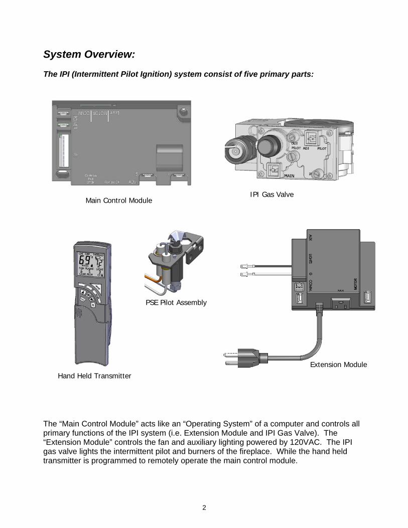
System Overview: The IPI (Intermittent Pilot Ignition) system consist of five primary parts:
The “Main Control Module” acts like an “Operating System” of a computer and controls all primary functions of the IPI system (i.e. Extension Module and IPI Gas Valve). The “Extension Module” controls the fan and auxiliary lighting powered by 120VAC. The IPI gas valve lights the intermittent pilot and burners of the fireplace. While the hand held transmitter is programmed to remotely operate the main control module.
Main Control Module IPI Gas Valve
Extension Module Hand Held Transmitter
PSE Pilot Assembly
3
Standard features of the IPI Control System are:
ON/OFF manual function of the fireplace system
Spark to pilot ignition system with continuous pilot option
Main Control Module that will learn up to three transmitters. Options of Wireless Wall mounted transmitters are also available.
Control System has a maximum Room Temperature Limit Shutdown feature of 95°F
whether the control is in manual ON or Thermostat ON mode, within the hand held transmitter
Communication and Thermal Safety within the Main Control Module, at 170°F, within the main control module
All 120V items controlled by the Extension Module are connected to the Main Control Module via a 12-inch long communication wire with 4-pin connectors on both ends
Optional battery back up (via four AA batteries) if electrical power is lost to provide
power to burn the fireplace, however fan and light kit will not function.
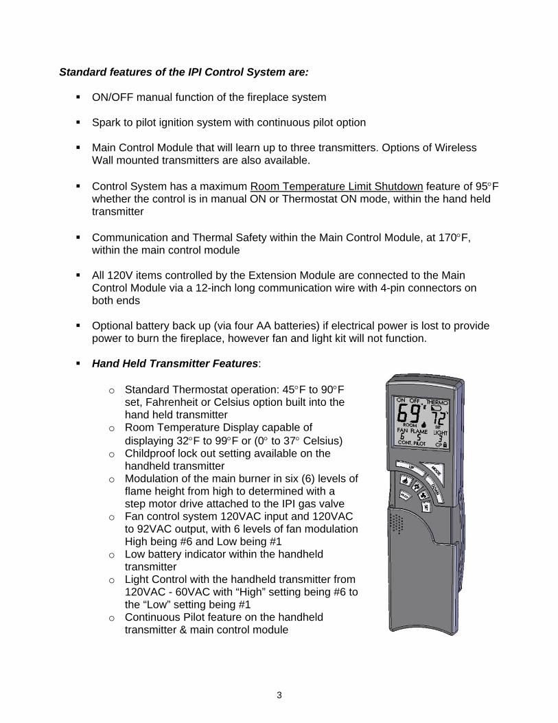
Hand Held Transmitter Features:
o Standard Thermostat operation: 45°F to 90°F set, Fahrenheit or Celsius option built into the hand held transmitter
o Room Temperature Display capable of displaying 32°F to 99°F or (0° to 37° Celsius)
o Childproof lock out setting available on the handheld transmitter
o Modulation of the main burner in six (6) levels of flame height from high to determined with a step motor drive attached to the IPI gas valve
o Fan control system 120VAC input and 120VAC to 92VAC output, with 6 levels of fan modulation High being #6 and Low being #1
o Low battery indicator within the handheld transmitter
o Light Control with the handheld transmitter from 120VAC - 60VAC with “High” setting being #6 to the “Low” setting being #1
o Continuous Pilot feature on the handheld transmitter & main control module

4
Operating the IPI System Once the Main Control Module “learns” the hand held transmitter the operation of the system is as follows: Mode Button - Hand Held Transmitter (offers over 1,000,000 security codes) Push Mode Button one time for Manual ON, the flame ICON will be visible on the LCD screen. Pushing the Mode Button a second time will change control to THERMO mode. Pushing the Mode Button a third time to turn the fireplace OFF. Note: The Mode Button operates “ON”, “THERMO” & “OFF” only. Manual Position – When the fireplace is turned “ON” manually the word ON will appear in the screen, when turned “OFF” the word OFF will appear. Thermostat (THERMO) Position – The working range for the room temperature readout it 32-90°F and the room temperature will always display on the LCD screen. The working range for set temperature is 45-90°F. It is factory set at 45°F. The user must use the UP/DOWN button to set the desired temperature. Remember: The set temperature will only appear when the hand held remote is in the THERMO mode. Flame Icon – The flame icon will be visible all any time the main burner is ON, whether it is under Manual ON or THERMO mode.
5
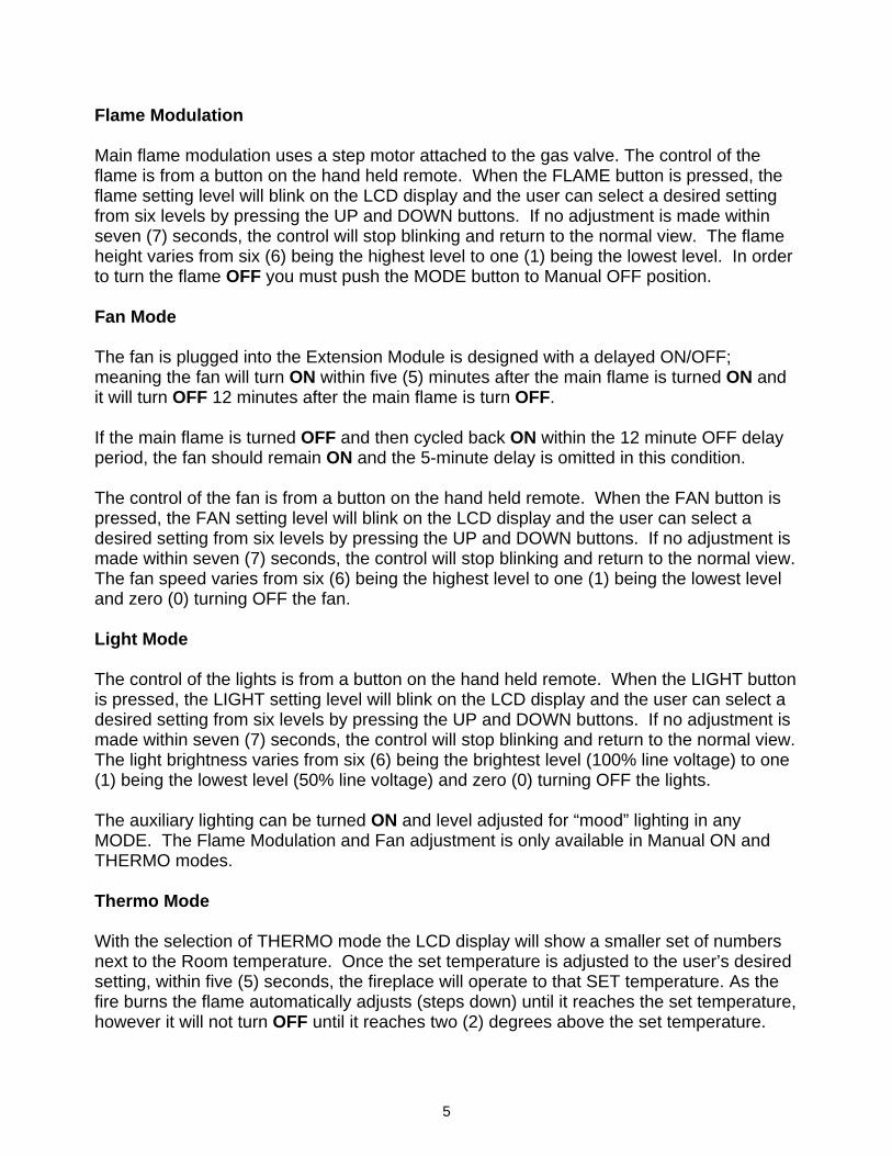
Flame Modulation Main flame modulation uses a step motor attached to the gas valve. The control of the flame is from a button on the hand held remote. When the FLAME button is pressed, the flame setting level will blink on the LCD display and the user can select a desired setting from six levels by pressing the UP and DOWN buttons. If no adjustment is made within seven (7) seconds, the control will stop blinking and return to the normal view. The flame height varies from six (6) being the highest level to one (1) being the lowest level. In order to turn the flame OFF you must push the MODE button to Manual OFF position. Fan Mode The fan is plugged into the Extension Module is designed with a delayed ON/OFF; meaning the fan will turn ON within five (5) minutes after the main flame is turned ON and it will turn OFF 12 minutes after the main flame is turn OFF. If the main flame is turned OFF and then cycled back ON within the 12 minute OFF delay period, the fan should remain ON and the 5-minute delay is omitted in this condition. The control of the fan is from a button on the hand held remote. When the FAN button is pressed, the FAN setting level will blink on the LCD display and the user can select a desired setting from six levels by pressing the UP and DOWN buttons. If no adjustment is made within seven (7) seconds, the control will stop blinking and return to the normal view. The fan speed varies from six (6) being the highest level to one (1) being the lowest level and zero (0) turning OFF the fan. Light Mode The control of the lights is from a button on the hand held remote. When the LIGHT button is pressed, the LIGHT setting level will blink on the LCD display and the user can select a desired setting from six levels by pressing the UP and DOWN buttons. If no adjustment is made within seven (7) seconds, the control will stop blinking and return to the normal view. The light brightness varies from six (6) being the brightest level (100% line voltage) to one (1) being the lowest level (50% line voltage) and zero (0) turning OFF the lights. The auxiliary lighting can be turned ON and level adjusted for “mood” lighting in any MODE. The Flame Modulation and Fan adjustment is only available in Manual ON and THERMO modes. Thermo Mode With the selection of THERMO mode the LCD display will show a smaller set of numbers next to the Room temperature. Once the set temperature is adjusted to the user’s desired setting, within five (5) seconds, the fireplace will operate to that SET temperature. As the fire burns the flame automatically adjusts (steps down) until it reaches the set temperature, however it will not turn OFF until it reaches two (2) degrees above the set temperature.
6
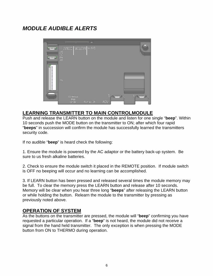
MODULE AUDIBLE ALERTS LEARNING TRANSMITTER TO MAIN CONTROLMODULE Push and release the LEARN button on the module and listen for one single “beep”. Within 10 seconds push the MODE button on the transmitter to ON; after which four rapid “beeps” in succession will confirm the module has successfully learned the transmitters security code. If no audible “beep” is heard check the following: 1. Ensure the module is powered by the AC adaptor or the battery back-up system. Be sure to us fresh alkaline batteries. 2. Check to ensure the module switch it placed in the REMOTE position. If module switch is OFF no beeping will occur and no learning can be accomplished. 3. If LEARN button has been pressed and released several times the module memory may be full. To clear the memory press the LEARN button and release after 10 seconds. Memory will be clear when you hear three long “beeps” after releasing the LEARN button or while holding the button. Relearn the module to the transmitter by pressing as previously noted above. OPERATION OF SYSTEM As the buttons on the transmitter are pressed, the module will “beep” confirming you have requested a particular operation. If a “beep” is not heard, the module did not receive a signal from the hand held transmitter. The only exception is when pressing the MODE button from ON to THERMO during operation.
7
GAS TYPE SELECTION When converting the appliance from NG (Natural Gas) to LP (Liquid Propane) the appropriate step motor modulations must be changed by the following: Push and hold the LEARN button for 20 seconds. When you hear a single short “beep” (1 second in length you have selected LP type gas. When you hear a single long “beep” (3 seconds in length) you have selected NG type gas.
8
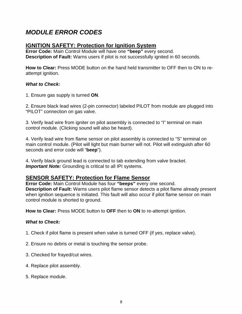
MODULE ERROR CODES IGNITION SAFETY: Protection for Ignition System Error Code: Main Control Module will have one “beep” every second. Description of Fault: Warns users if pilot is not successfully ignited in 60 seconds. How to Clear: Press MODE button on the hand held transmitter to OFF then to ON to re-attempt ignition. What to Check: 1. Ensure gas supply is turned ON. 2. Ensure black lead wires (2-pin connector) labeled PILOT from module are plugged into “PILOT” connection on gas valve. 3. Verify lead wire from igniter on pilot assembly is connected to “I” terminal on main control module. (Clicking sound will also be heard). 4. Verify lead wire from flame sensor on pilot assembly is connected to “S” terminal on main control module. (Pilot will light but main burner will not. Pilot will extinguish after 60 seconds and error code will “beep”). 4. Verify black ground lead is connected to tab extending from valve bracket. Important Note: Grounding is critical to all IPI systems. SENSOR SAFETY: Protection for Flame Sensor Error Code: Main Control Module has four “beeps” every one second. Description of Fault: Warns users pilot flame sensor detects a pilot flame already present when ignition sequence is initiated. This fault will also occur if pilot flame sensor on main control module is shorted to ground. How to Clear: Press MODE button to OFF then to ON to re-attempt ignition. What to Check: 1. Check if pilot flame is present when valve is turned OFF (if yes, replace valve). 2. Ensure no debris or metal is touching the sensor probe. 3. Checked for frayed/cut wires. 4. Replace pilot assembly. 5. Replace module.
9
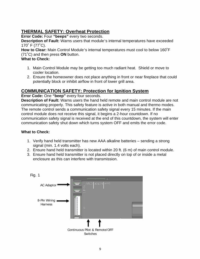
AC Adaptor
8-Pin Wiring Harness
Continuous Pilot & Remote/OFF Switches
THERMAL SAFETY: Overheat Protection Error Code: Four “beeps” every two seconds. Description of Fault: Warns users that module’s internal temperatures have exceeded 170˚ F (77˚C). How to Clear: Main Control Module’s internal temperatures must cool to below 160˚F (71˚C) and then press ON button. What to Check:
1. Main Control Module may be getting too much radiant heat. Shield or move to cooler location.
2. Ensure the homeowner does not place anything in front or near fireplace that could potentially block or inhibit airflow in front of lower grill area.
COMMUNICATION SAFETY: Protection for Ignition System Error Code: One “beep” every four seconds. Description of Fault: Warns users the hand held remote and main control module are not communicating properly. This safety feature is active in both manual and thermo modes. The remote control sends a communication safety signal every 15 minutes. If the main control module does not receive this signal, it begins a 2-hour countdown. If no communication safety signal is received at the end of this countdown, the system will enter communication safety shut down which turns system OFF and emits the error code. What to Check:
1. Verify hand held transmitter has new AAA alkaline batteries – sending a strong signal (min. 1.4 volts each).
2. Ensure hand held transmitter is located within 20 ft. (6 m) of main control module. 3. Ensure hand held transmitter is not placed directly on top of or inside a metal
enclosure as this can interfere with transmission.
Fig. 1

10
AC Power Adaptor AC adaptor is a transformer that converts VAC to VDC power. Ensure the electrical circuit you are using has 120VAC power. The adaptor is rated at 7.5 VDC and must produce a minimum of 5.4 VDC in order to operate an IPI system. Extension Module The Extension Module controls both the fan and the lights and is connected by a 4-Pin COMM wire set to the MAIN Control Module. The main flame must be turned ON for a minimum of 5 minutes (“warm up period”) before the fan will come ON. IMPORTANT NOTE: If the transmitter turns appliance OFF then back ON the during the “warm up” period, the 5 minute time frame starts over again. This can cause some users to believe the fan is not operating properly if time exceeds 10 minutes.
To AC Power
Fan Outlet
Not Currently Used
Fig. 4
Fig. 2
Fig. 3
11
TROUBLE SHOOTING SECTION Before trouble shooting be sure you look for obvious things such as frayed/damage wires, loose or disconnected wires and properly connected components. In addition double check the low rate screw and verify the valve and module switches for the appliance your are servicing with the reference guide on page 18. Main Control Module Will Not Learn Hand Held Transmitter 1. Ensure the REMOTE/OFF switch, on the side of the Main Control Module (See fig. 1, pg. 9) is set to REMOTE. 2. Make sure the batteries in the hand held transmitter are installed in the proper direction and are not weak. Individual battery voltage should be no less than 1.4V for AA or AAA. 3. Verify the hand held transmitter is sending a signal. With hand held transmitters the LCD display should indicate ON or OFF depending which button is being pressed. Buttons should be pressed and held for 1 to 2 seconds to ensure that a complete signal is sent and an audible “beep” can be heard. 4. Make sure that the hand held transmitter is within the 20-foot operational range of the receiver. 5. Check the A/C Power Adaptor; make sure the leads from the adaptor are securely connected to the POWER terminals on the control module (See fig. 1, pg. 9). Test adaptor using a multi-meter. Unplug the two (2) spade connectors from the module at the POWER connection. Ensure the adaptor is plugged into 120VAC. Using meter in VDC setting insert leads into each of the spade connectors. Voltage should be 7.5 VDC, minimum of 5.4 VDC. If voltage is less than 5.4 VDC, replace the adaptor. 6. Press the learn button on the Main Control Module and release after 10 seconds. You should hear three (3) long audible beeps indicating all codes have cleared. Next press and release the learn button (you should hear a single audible beep from the receiver), immediately press the MODE button on the hand held transmitter (you should hear a series of four rapid “beeps” in succession indicating the hand held transmitter code has been learned). If no “beeps” are heard at anytime, replace module. Ignitor Will Not Spark 1. Ensure ignitor is connected to Main Module properly. “I” for ignitor and “S” for sensor (See pg. 6). 2. Ensure power is supplied from AC adaptor. See “Main Control Module Will Not Learn Hand Held Transmitter” section; Step # 5 to test adaptor. 3. Listen to ensure communication is heard by a “beep” when hand held transmitter MODE button is pressed ON.
12
Ignitor Will Not Spark Continued 4. Listen to module, if “ticking” is occurring inside Main Control Module check for loose wires, reversed wires or no ground. 5. Ensure ground wire from module is connected to unpainted metal surface, which also grounds the pilot assembly 6. Check for any wire extensions, cuts or frayed wire. 7. Spark gap at pilot assembly may be too large or too small. Proper gap should be approximately 1/8” (3mm) from probe to pilot hood. 8. Check ceramic insulators around probe and sensor of pilot assembly. Ensure insulator is not cracked or broken. If so, replace pilot assembly. 9. Ignitor cannot touch any metal surface. If so, adjust as needed. 10. Test continuity of pilot assembly using a multi-meter. Remove the pilot assembly wires from module at “I” (ignitor) and “S” (sensor). Using a meter set on continuity touch one lead to spade connector of sensor wire and the other to the sensor probe. Meter should have an audible sound verifying continuity. Test ignitor wire in same manner. If no continuity is found replace the pilot assembly. Pilot Will Not Light or Stay Lit (Ignitor Will Not Spark or is Intermittent)
It’s important to understand the functions of the pilot assembly. The Pilot Hood is the path where the gas flows to be ignited. The pilot orifice inside the pilot assembly controls the gas flow. The function of the Ignitor is to spark across the pilot hood igniting the gas when it arrives. The function of the Sensor is to recognize when the flame is present, rectify the flame, turning off the ignitor and simultaneously sending VDC current to open the valve allowing gas to flow into main burner. NOTE: IPI pilot assemblies can be subject to “siliconization”. This is a process that can occur when silicone sealants are used inside a sealed chamber. When heated these sealants can emit air-borne particles inside a firebox that can adhere to the ignitor and sensor rods of a pilot assembly. This in turn can cause pilots not to function properly or operate intermittently. Until the firebox is used for a period of time the only course of action is to use emery cloth to clean the rods. Pilot Will Not Light or Stay Lit (Ignitor Will Not Spark or is Intermittent) 1. Verify that gas supply is turned ON. 2. Verify the Main Control Module is receiving the signal from the hand held transmitter by listening for a “beep” from the module when MODE is pressed on the transmitter. If you do not hear a beep, try again or re-learn module to the hand held transmitter. NOTE: It is recommended to turn ON continuous pilot at the main control module during heating season to keep firebox warm. 3. Ensure the lead wire from the pilot assembly igniter is securely connected to terminal labeled “I” and the sensor lead wire from the flame rectification sensor is securely connected to the terminal
13
labeled “S” on the Main Control Module (See pg. 6). 4. Ensure the black GROUND wire is securely connected to an appropriate metal portion of the valve or pilot assembly. A proper ground is essential to spark igniter operation. 5. Ensure pilot adjustment screw is not closed. Pilot screw is should be almost “flush” to the cast port. If pilot screw is recessed more than approximately 3/16” it is most likely closed and will not allow gas flow. Open by turning counter clockwise. 6. Make certain that the pilot flame is touching the flame rectification sensor rod on the pilot assembly. This gas valve is equipped with a pilot flame adjustment screw (See IPI Valve Pg. 2). If the pilot flame is too small it may not contact the flame rectification sensor and will not complete the safety circuit. Adjust pilot flame if needed. 7. Make sure that the 2-pin connector leads from the Main Control Module are securely connected to the terminals labeled “PILOT” on the gas valve body (See IPI Valve Pg. 2). Note: 2-pin connectors are not polarity sensitive. 8. Check the resistance of PILOT coil at the gas valve. Remove the 2-pin connector labeled PILOT from the gas valve. Using a multi-meter touch one lead to each pin and measure resistance of the two pins. A good reading should be 990-Ohms to 1230-Ohms. If the resistance falls outside of these limits, replace the gas valve. 9. Test power to gas valve. Using a multi-meter set for VDC in insert each test lead wire into the 2-pin connector on gas valve labeled PILOT. Turn the appliance ON and watch voltage on mute-meter. For approximately one second there should be 6VDC then drop down to 1.5 VDC. Same voltage will occur on MAIN side of gas valve. If no voltage present to valve; check the AC adaptor on page 10. If voltage is present at gas valve and you have confirmed power from AC adaptor then replace the 8-pin wiring harness. Pilot Flame is ON / Will Not Extinguish 1. Check the hand held transmitter display for the words “CONT. PILOT” on the LCD screen. If this is displayed, press and hold the PILOT button on the hand held transmitter for approximately 10 seconds to turn OFF the Continuous Pilot mode. NOTE: IF “Continuous Pilot-OFF/On” switch is activated ON at the Main Control Module the hand held transmitter will not turn OFF the continuous pilot on the appliance even though it is not displayed on the LCD screen (See pg. 3 & Fig. #1 pg. 9) Temperature Display on Hand Held Transmitter is Not Correct 1. Ensure the hand held transmitter was not recently stored in a different environment (air-conditioned, heated) from that in which the transmitter is being tested. It may take up to 3 hours for the temperature inside a packaged transmitter, and several minutes for an unpackaged transmitter, to equalize with the room temperature. 2. If LCD display continues to show incorrect temperatures or numbers then replace the batteries. If new batteries do not make a change then replace the hand held transmitter.

14
Main Burner Won’t Light 1. Ensure the hand held transmitter is “learned” to the Main Control Module (See pg 6) and you can hear a “beep” from the module. 2. Ensure the pilot is burning and ignitor has stopped sparking. 3. Check the Main Control Module to ensure the REMOTE/OFF switch is in the REMOTE position. 4. Check for power to the module by testing the AC Power Adaptor. See “Main Control Module Will Not Learn Hand Held Transmitter” section; Step # 5.
5. Test voltage at gas valve. Use a multi-meter set for VDC in insert each test lead wire into the 2-pin connector on the gas valve labeled MAIN. Turn appliance ON and watch for voltage to occur. For approximately one second there should be 6VDC then drop down to 1.5 VDC. Same voltage will occur on PILOT side of gas valve. If no voltage occurs to the valve, check the AC adaptor on page 10. Replace AC adaptor if no voltage is present. See fig. 5. 6. Check the resistance of Main burner coil at the gas valve. Remove the 2-pin connector labeled MAIN from the gas valve. Using a multi-meter touch one lead to each pin and measure coil resistance. A good reading should be 990-Ohms to 1230-Ohms. If the resistance falls outside of these limits, replace the gas valve. See fig. 6. Transmitter Will Not Operate in THERMO Mode 1. Ensure the hand held transmitter is within the 20-foot operational range. 2. THERMO mode only operates when the LCD screen reads THERMO in the upper portion of the screen. Push MODE button on hand held transmitter until you see the word THERMO. 3. Verify set temperature on the hand held transmitter is at least 2 degrees above or below the room temperature. THERMO will not turn ON when less than 2 degrees of the set temperature.
Fig. 5
Fig. 6
Fig. 6
15
Transmitter Will Not Operate in THERMO Mode Continued 4. If THERMO mode fails to operate correctly, then clear the codes from the Main Control Module and re-learn the hand held transmitter to the module. See page 6. 5. Replace hand held transmitter If THERMO mode fails to operate after re-learning. Fan Will Not Turn ON 1. Ensure the main flame has been turned ON for at least 5 minutes and the hand held transmitter reads “6” below FAN on the LCD display. 2. Plug the fan directly into an energized 120VAC wall outlet to check if motor functions properly when powered external from the appliance. 3. Check the communication wire (COMM) & connections for any defects. Disconnect the communication wire (COMM) from both the Main Control module and the Extension Module. Look at both ends of the wire connectors and make sure the wire colors are in the same order on both connectors. If colors do not match, replace COMM wire. Make sure the wires are firmly seated in the plastic connectors and not pushed out. 4. Make sure no wires appear to be broken or frayed. Make sure that all of the pins on the mating connectors of the Main Control and Extension Modules are intact, not bent, damaged. 5. Use a multi-meter to check the continuity of each of the 4 wires in the wire harness, checking the same color wire on each end (be sure to use meter leads with sharp enough tips to make contact with the metal tabs in the plastic connector). 6. Firmly plug the communication wire back into the Main Control Module and Extension Module then re-check fan operation. 7. Check the LIGHT output by disconnecting the extension module from AC power for safety. Place the LIGHT setting on the hand held transmitter to “0” or OFF. 8. Connect an approved light kit to the LIGHT output of the extension module. Ensure the connections to the LIGHT output are not touching each other or any other metal. 9. Plug the extension module back into the AC power supply. The light should be OFF. Place the LIGHT setting on hand held transmitter to “6” or HI. Light should turn ON. NOTE: A multi-meter cannot be used for this test unless a light (load) is connected to the output. If the LIGHT output can be turned ON and OFF from the steps above, the problem is LIGHT output circuit on the extension module is not operating and the extension module should be replaced. 10. If the light out put functions properly, the problem is with the FAN output of the Extension Module. Replace Extension Module. 11. If the LIGHT output does not function either, and no defects were found with the
16
Fan Will Not Turn ON Continued communication wire, the problem is likely a communication issue between the Main Control Module and Extension Module caused by an internal problem with one of the two modules. If the problem still persists, replace the Main Module. Lights Will Not Turn ON NOTE: Not all appliances are equipped with a light kit therefore this section will not be applicable to all products. 1. Ensure the Extension Module is plugged into an energized 120VAC outlet and 4-Pin COMM wire harness is connected to the Main Control Module. 2. Be sure the transmitter has been “learned” to the Main Control Module for proper communication. 3. Check the individual light bulb/s to ensure they are not broken and properly installed into the light socket/s. Ensure the connection from light kit to the Extension Module is securely wired properly according to product wiring diagram (See pgs.19-20). 4. Check the communication wire (COMM) & connections for any defects. Make sure no wires appear to be broken or frayed. 5. Firmly plug the communication wire back into the Main Control Module and the Extension Module then re-check light operation. 6. With light plugged in, test VAC power at the two lead (red & white) wires from the Extension Module by pressing the LIGHT button on the hand held transmitter and adjust LIGHT to “6” or HI. Using a multi-meter on VAC check to ensure 120VAC is present. Replace the Extension Module if no power is present. 7. Test the varying voltage (dimming of lights) by pressing the hand held transmitter LIGHT button (watch number “blink") then press down button to test for a drop in voltage. Ensure a “beep” is heard from Main Control Module to recognize command.
17
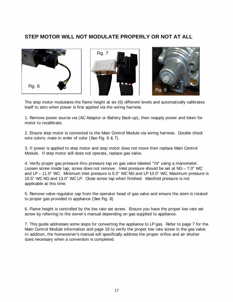
STEP MOTOR WILL NOT MODULATE PROPERLY OR NOT AT ALL
The step motor modulates the flame height at six (6) different levels and automatically calibrates itself to zero when power is first applied via the wiring harness. 1. Remove power source via (AC Adaptor or Battery Back-up), then reapply power and listen for motor to recalibrate. 2. Ensure step motor is connected to the Main Control Module via wiring harness. Double check wire colors; mate in order of color (See Fig. 6 & 7). 3. If power is applied to step motor and step motor does not move then replace Main Control Module. If step motor still does not operate, replace gas valve. 4. Verify proper gas pressure thru pressure tap on gas valve labeled “IN” using a manometer. Loosen screw inside tap; screw does not remove. Inlet pressure should be set at NG – 7.0” WC and LP – 11.0” WC. Minimum inlet pressure is 5.0” WC NG and LP 10.0” WC. Maximum pressure is 10.5” WC NG and 13.0” WC LP. Close screw tap when finished. Manifold pressure is not applicable at this time. 5. Remove valve regulator cap from the operator head of gas valve and ensure the stem is rotated to proper gas provided to appliance (See Fig. 8) 6. Flame height is controlled by the low rate set screw. Ensure you have the proper low rate set screw by referring to the owner’s manual depending on gas supplied to appliance. 7. This guide addresses some steps for converting the appliance to LP gas. Refer to page 7 for the Main Control Module information and page 18 to verify the proper low rate screw in the gas valve. In addition, the homeowner’s manual will specifically address the proper orifice and air shutter sizes necessary when a conversion is completed.
Fig. 6
Fig. 7
Fig. 8
18
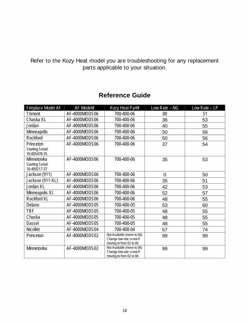
Refer to the Kozy Heat model you are troubleshooting for any replacement parts applicable to your situation.
Reference Guide Fireplace Model AF AF Model# Kozy Heat Part# Low Rate – NG Low Rate – LP Trimont AF-4000MODS06 700-400-06 00 51 Chaska XL AF-4000MODS06 700-400-06 36 53 Jordan AF-4000MODS06 700-400-06 40 55 Minneapolis AF-4000MODS06 700-400-06 50 56 Rockford AF-4000MODS06 700-400-06 50 56 Princeton Starting Serial: 10-005478-35
AF-4000MODS06 700-400-06 37 54
Minnetonka Starting Serial: 10-409217-37
AF-4000MODS06 700-400-06 35 53
Jackson (911) AF-4000MODS06 700-400-06 0 50 Jackson (911-XL) AF-4000MODS06 700-400-06 35 51 Jordan XL AF-4000MODS06 700-400-06 42 53 Minneapolis XL AF-4000MODS06 700-400-06 52 57 Rockford XL AF-4000MODS06 700-400-06 48 55 Delano AF-4000MODS05 700-400-05 53 60 TRF AF-4000MODS05 700-400-05 48 55 Chaska AF-4000MODS05 700-400-05 48 55 Dassel AF-4000MODS05 700-400-05 48 55 Nicollet AF-4000MODS04 700-400-04 57 74 Princeton AF-4000MODS02 Not Available (move to 06)
Change low rate screw if moving to from 02 to 06
99 99
Minnetonka AF-4000MODS02 Not Available (move to 06) Change low rate screw if moving to from 02 to 06
99 99
19
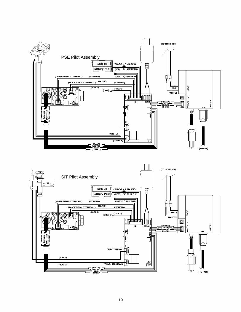
PSE Pilot Assembly
SIT Pilot Assembly