Embed Size (px)
Citation preview
CONTENTS..........................................................................PAGE
Dimensions ..................................................................................2
Gas Orifice Sizes ........................................................................2
Installation Requirements:
Boiler Location ........................................................................3
Boiler Foundation ....................................................................3
Chimney Requirements ..........................................................3
Minimum Clearance ....................................................................4
Vent Piping ..............................................................................4
Gas Piping ..................................................................................4
Electrical Controls and Wiring ................................................5
Boiler Room Air Supply and Ventilation ..................................5
Draft Hood Installation ............................................................5
Piping at Boiler—Water Boilers ..............................................5
Vent Damper Installation ........................................................6
Operating Instructions..................................................................7
Filling and Venting Water Systems..........................................7
Initial Start, Safety & Lighting Instructions ..............................8
Burner Adjustment, Checking Gas Input ................................8
Controls, Safety Check ..........................................................9
Care and Maintenance ................................................................9
Safety Check for Control System..........................................10
Protection From Freezing......................................................10
Water Treatment ....................................................................10
Sequence of Operations ............................................................11
Wiring Diagram ..........................................................................12
Trouble Shooting Guide ............................................................13
Piping a Heating and Cooling System ......................................14
Replacement Parts ....................................................................14
Appendix A ................................................................................15
IMPORTANTREAD ALL OF THE FOLLOWING WARNINGSAND STATEMENTS BEFORE READING THE
INSTALLATION INSTRUCTIONS
WARNINGLIQUEFIED PETROLEUM (L.P.)
PROPANE FIRED GAS BOILERS
Installation location ONLY as permitted in paragraph entitled"LIQUEFIED PETROLEUM (L.P.) PROPANE GAS FIREDBOILER LOCATION" on page 3 of this instruction book.The above warning does not apply to NATURAL gas fired boilers.
The installation must conform to the requirements of the authori-ty having jurisdiction or, in the absence of such requirements, tothe National Fuel Gas Code, ANSI Z223.1-latest edition. Theinstallation must also conform to the additional requirements inthis Slant/Fin Instruction Book.
In addition, where required by the authority having jurisdiction,the installation must conform to American Society of MechanicalEngineers Safety Code for Controls and Safety Devices forAutomatically Fired Boilers, No. CSD-1.
This manual must be left with owner and should be hung on oradjacent to the boiler for reference.
WARNINGThis boiler, gas piping and accessories must be installed, con-nected, serviced and repaired by a trained, experienced servicetechnician, familiar with all precautions required for gas firedequipment and licensed or otherwise qualified, in compliancewith the authority having jurisdiction.
HOT WATER—Models GG-300 through GG-399HES
INSTALLATION AND OPERATING INSTRUCTIONSGALAXY GAS-FIRED CAST IRON BOILERS FOR NATURAL
AND L.P. PROPANE GASESINTERMITTENT PILOT IGNITION™
Printed in U.S.A. 516 PUBLICATION GG-40SPart No. 41-2842
Heating Contractor
Address
Phone Number
Boiler Model Number
Boiler Serial Number
Installation Date
CANADIAN ENERGYPERFORMANCE
VERIFIEDRENDEMENT
ENERGETIQUEVERIFIE
2 GALAXY
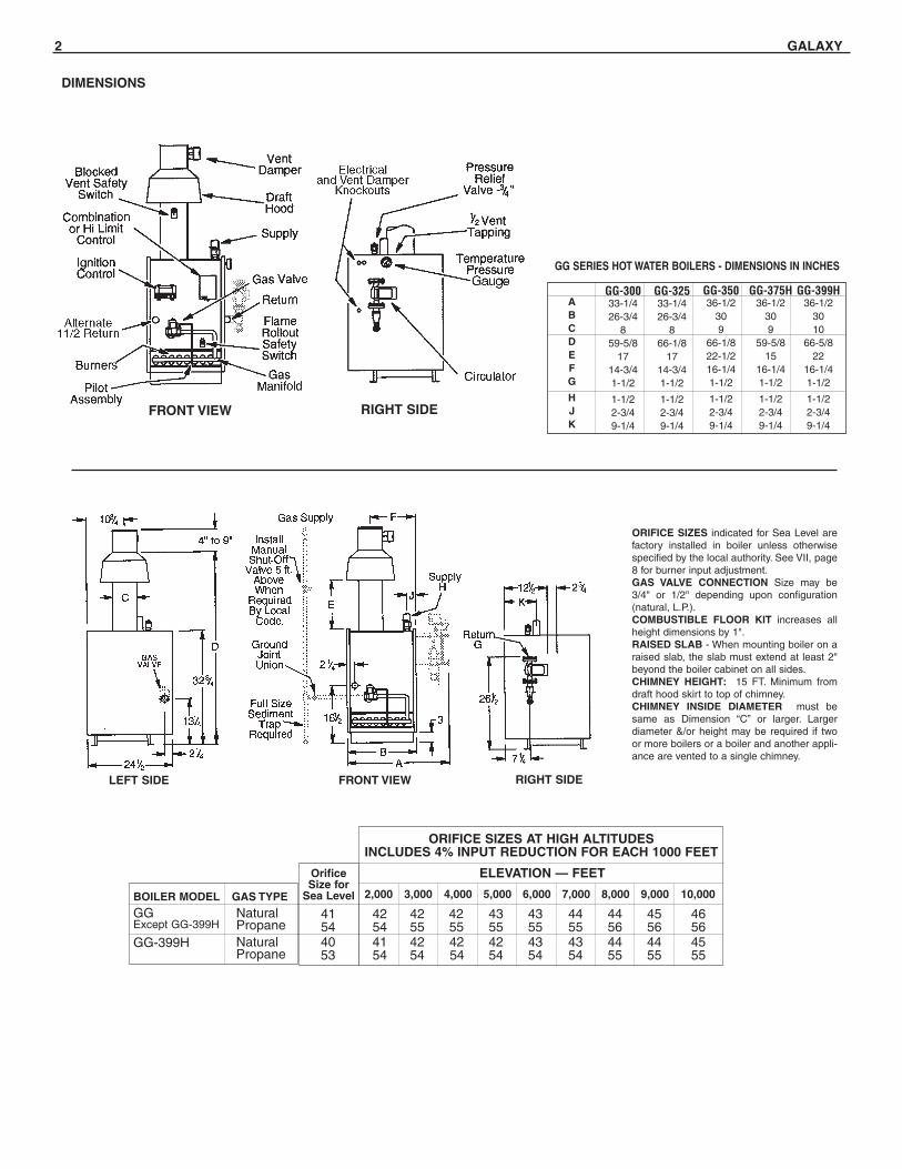
ORIFICE SIZES indicated for Sea Level arefactory installed in boiler unless otherwisespecified by the local authority. See VII, page8 for burner input adjustment.GAS VALVE CONNECTION Size may be3/4" or 1/2" depending upon configuration(natural, L.P.).COMBUSTIBLE FLOOR KIT increases allheight dimensions by 1".RAISED SLAB - When mounting boiler on araised slab, the slab must extend at least 2"beyond the boiler cabinet on all sides.CHIMNEY HEIGHT: 15 FT. Minimum fromdraft hood skirt to top of chimney. CHIMNEY INSIDE DIAMETER must besame as Dimension “C” or larger. Largerdiameter &/or height may be required if twoor more boilers or a boiler and another appli-ance are vented to a single chimney.
ORIFICE SIZES AT HIGH ALTITUDESINCLUDES 4% INPUT REDUCTION FOR EACH 1000 FEET
ELEVATION — FEET
BOILER MODEL
GGExcept GG-399H
GG-399H
GAS TYPE
NaturalPropaneNaturalPropane
OrificeSize for
Sea Level
41544053
42544154
42554254
42554254
43554254
43554354
44554354
44564455
45564455
46564555
2,000 3,000 4,000 5,000 6,000 7,000 8,000 9,000 10,000
ABCDEFG
HJK
GG-30033-1/426-3/4
859-5/8
1714-3/41-1/2
1-1/22-3/49-1/4
GG-32533-1/426-3/4
866-1/8
1714-3/41-1/2
1-1/22-3/49-1/4
GG-35036-1/2
309
66-1/822-1/216-1/41-1/2
1-1/22-3/49-1/4
GG-375H36-1/2
309
59-5/815
16-1/41-1/2
1-1/22-3/49-1/4
GG-399H36-1/2
3010
66-5/822
16-1/41-1/2
1-1/22-3/49-1/4
GG SERIES HOT WATER BOILERS - DIMENSIONS IN INCHES
FRONT VIEW
LEFT SIDE FRONT VIEW
RIGHT SIDE
RIGHT SIDE
DIMENSIONS
GALAXY 3
INSTALLATION REQUIREMENTSThe installation must conform to the requirements of the author-ity having jurisdiction or, in the absence of such requirements,to the National Fuel Gas Code, ANSI Z223.1-latest edition.
This installation must also conform to the additional require-ments in this Slant/Fin instruction book. Installation and serviceto be performed by a qualified installer, service agency or thegas supplier.
NATURAL GAS FIRED BOILER LOCATION—
Provide a level, solid foundation for the boiler. Location shouldbe as near the chimney as possible so that the flue pipe fromboiler to chimney is short and direct.
Automatic gas ignition system components shall be installed sothese components will not be subjected to dripping water duringinstallation or service.
CHIMNEY REQUIREMENTS—A. Galaxy boilers may be vented into a masonry vitreous tile-
lined chimney or UL LISTED type “B” venting system NOTEXPOSED to the OUTDOORS below the roof line.Venting and sizing of venting system must be in accordancewith Part 7, Part 11 and Appendix G of the National FuelGas Code ANSI Z223.1, NFPA 54, -latest edition which willbe referred to as the National Fuel Gas Code. Local codesapply.If a masonry chimney is exposed to the outdoors on one ormore sides below the roof line (exterior chimney), ONE ofthe following options apply:1. Chimney must be re-lined with a UL LISTED metallic liner.
When this is done, the chimney will be considered NOTexposed to the outdoors and the requirements of theNational Fuel Gas Code for NON-exposed chimneysand/or local codes will apply.
2. If an exposed tile-lined chimney is to be used WITHOUT aUL LISTED metallic liner, the boiler must meet the require-ments of the National Fuel Gas Code:
B. If an existing boiler is removed from a common venting sys-tem, the common venting system may be too large for prop-er venting of the remaining appliances connected to thecommon vent. Follow the test procedure shown in Appendix"A" on page 15 of this manual to insure proper operation ofventing system and appliances.
C. Inspect for proper and tight construction. Any restrictions orobstructions must be removed. An existing chimney mayrequire cleaning.
D.Chimney or vent must extend at least 3 feet above its pas-sage through a roof and at least 2 feet above any ridge within10 feet of the chimney.
BOILER FOUNDATION
A. Provide a solid, level foundation, capable of supporting theweight of the boiler filled with water, and extending at least2" past the jacket on all sides. See dimensions of boilers,page 2.
B. For installation on non-combustible floors only.*
C. If boiler is to be located over buried conduit containing elec-tric wires or telephone cables, consult local codes or theNational Board of Fire Underwriters for specific require-ments.* The Combustible Floor Kit part number printed on the boiler rating plate is
the only one to be used when installing on combustible floors. The boilermust not be installed on carpeting.
WARNINGSPECIAL ATTENTION FOR LIQUEFIED PETROLEUM
(L.P.) PROPANE GAS-FIRED BOILER INSTALLATIONS
LPG appliances (boilers) shall be installed in accordancewith applicable provisions of NFPA 58 ( Liquefied PetroleumGas Code) latest edition for installations in US andCAN/CGA B149.1 latest edition for installations in Canada.
Liquefied Petroleum (LP) propane gas is heavier than airtherefore Propane gas accumulate at floor level. If you sus-pect a leak, do not attempt to operate boiler. A spark orflame from the appliance (boiler) or other sources may ignitethe accumulated propane gas causing an explosion or fire.It is recommended that inspections for gas leaks be per-formed periodically by licensed professional and that leakdetection devices be installed as a further safety measure.
4 GALAXY
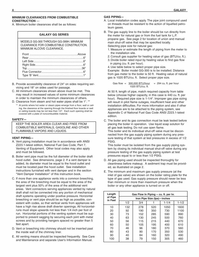
MINIMUM CLEARANCES FROM COMBUSTIBLECONSTRUCTION — A. Minimum boiler clearances shall be as follows:
B. Provide accessibility clearance of 24" on sides requiring ser-vicing and 18" on sides used for passage.
C. All minimum clearances shown above must be met. Thismay result in increased values of some minimum clearancesin order to maintain the minimum clearances of others.
D. Clearance from steam and hot water pipes shall be 1". **** At points where hot water or steam pipes emerge from a floor, wall or ceil-
ing, the clearance at the opening through the finished floor boards or wallor ceiling boards may be not less than 1/2". Each such opening shall becovered with a plate of noncombustible material.
SAFETY—
KEEP THE BOILER AREA CLEAR AND FREE FROM COMBUSTIBLE MATERIALS, GASOLINE AND OTHER FLAMMABLE VAPORS AND LIQUIDS.
VENT PIPING—A. Vent piping installation must be in accordance with ANSI
Z223.1-latest edition, National Fuel Gas Code, Part 7,Venting of Equipment. Other local codes may also applyand must be followed.
B. Boiler vent pipe must be the full diameter of the boiler drafthood outlet. See dimensions, page 2. If a vent damper isadded, its diameter must be equal to the hood outlet andmust be located past the hood outlet. See installationinstructions furnished with vent damper and in the section"Vent Damper Installation" of this instruction book.
C. If more than one appliance vents into a common breeching,the area of the breeching must be equal to the area of thelargest vent plus 50% of the area of the additional ventareas. Vent connectors serving appliances vented by naturaldraft shall not be connected into any portion of mechanicaldraft systems operating under positive pressure. Horizontalbreeching or vent pipe should be as high as possible, con-sistent with codes, so that vertical vents from appliances willhave a high rise above draft diverter openings. All horizontal-runs must slope upwards not less than 1/4 inch per foot ofrun. Horizontal portions of the venting system must be sup-ported to prevent sagging by securing each joint with metalscrews and by providing hangers spaced no greater than 5feet apart.
D. Vent or breeching into chimney should not be inserted pastthe inside wall of the chimney liner.
E. All venting means should be inspected frequently. See Careand Maintenance and separate User's Information Manual.
GAS PIPING—A. Local installation codes apply. The pipe joint compound used
on threads must be resistant to the action of liquefied petro-leum gases.
B. The gas supply line to the boiler should be run directly fromthe meter for natural gas or from the fuel tank for L.P.propane gas. See page 2 for location of union and manualmain shut-off valve that may be specified locally.Selecting pipe size for natural gas:1. Measure or estimate the length of piping from the meter to
the installation site.2. Consult gas supplier for heating value of gas (BTU/cu. ft.).3. Divide boiler rated input by heating value to find gas flow
in piping (cu. ft. per hour).4. Use table below to select proper pipe size.Example: Boiler model GG-300 is to be installed. Distancefrom gas meter to the boiler is 50 ft. Heating value of naturalgas is 1020 BTU/cu. ft. Select proper pipe size.
At 50 ft. length of pipe, match required capacity from tablebelow (choose higher capacity, in this case is 440 cu. ft. perhour). Required pipe size is 1-1/4". Improper gas pipe sizingwill result in pilot flame outages, insufficient heat and otherinstallation difficulties. For more information and also if otherappliances are to be attached to the piping system, seeAppendix C of National Fuel Gas Code ANSI Z223.1-latestedition.
C. The boiler and its gas connection must be leak tested beforeplacing the boiler in operation. Use liquid soap solution forall gas leak testing. Do not use open flame.This boiler and its individual shut-off valve must be discon-nected from the gas supply piping system during any pres-sure testing of that system at test pressures in excess of 1/2PSIG.This boiler must be isolated from the gas supply piping sys-tem by closing its individual manual shut-off valve during anypressure testing of the gas supply piping system at testpressures equal to or less than 1/2 PSIG.
D. All gas piping used should be inspected thoroughly forcleanliness before makeup. A sediment trap must be provid-ed, as illustrated on page 2.
E. The minimum and maximum gas supply pressure (at theinlet of gas valve) are shown on the boiler rating plate for thetype of gas used. Gas supply pressure should never be lessthan minimum or more than maximum pressure when theboiler or any other appliance is turned on or off.
1/2 3/4 1 1-1/4 1-1/2
10 132 278 520 1050 160020 92 190 350 730 110030 73 152 285 590 89040 63 130 245 500 76050 56 115 215 440 67060 50 105 195 400 61070 46 96 180 370 56080 43 90 170 350 53090 40 84 160 320 490
100 38 79 150 305 460
Lengthof Pipein Feet
Gas Flow In Piping -- cu. ft. per hr.
Iron Pipe Size (Ips)—inches
Gas flow = 300,000 BTU/hour = 294 cu. ft. per hour1020 BTU/cu. ft.
GALAXY GG SERIES
MODELS GG-300 THROUGH GG-399H. MINIMUMCLEARANCE FOR COMBUSTIBLE CONSTRUCTION.MINIMUM ALCOVE CLEARANCE.
Front ..............................................................AlcoveRear ......................................................................6"Left Side ................................................................6"Right Side..............................................................6"Top ......................................................................36"Flue Connector......................................................6"Type 'B' Vent..........................................................1"
GALAXY 5
ELECTRICAL WIRINGDANGER: Before wiring, always turn off electric power supply, otherwise shock or death can result.
Power SupplyA separately fused circuit is recommended. Use a standard 15 Amp. fuse or breaker and 14 gauge conductors in BX cable or circuit.Provide disconnect means and overload protec-tion as required. See boiler wiring diagram (Figure 6). Boilermust be electrically grounded in accordance with requirementsof the authority having jurisdiction, or, in the absence of suchrequirements, with the National Electrical Code, ANSI/NFPA70-latest edition.
BOILER ROOM AIR SUPPLY AND VENTILATIONAn ample supply of air is required to obtain combustion andventilation. Room temperature over 100°F may cause nuisancetripping of the Blocked Vent Safety Switch.
ALL AIR MUST COME FROM OUTSIDE, directly through wallopenings to the boiler or through unsealed openings aroundwindows, doors, etc. in the whole building. When buildings areinsulated, caulked and weather-stripped, now or later on, directopening to outside may be required and should be provided. Ifthe boiler is not on an outside wall, air may be ducted to it fromoutside wall openings.
The National Fuel Gas Code, ANSI Z223.1-latest edition speci-fies openings for air under various conditions. Local codes may
specify minimum opening sizes and locations. The followingrecommendation applies to buildings of energy-saving construc-tion, fully caulked and weather stripped:
Provide one GRILLED opening near the floor and one near theceiling on an outside wall near the boiler (or duct from suchopenings to the boiler), EACH opening to be a minimum of onesquare inch per 2000 Btuh input to ALL APPLIANCES in thearea. For a total appliance input of 200,000 Btuh, each open-ing will be 100 square inches. A grilled opening 10" x 10" has100 square inches of area. If fly screen must be used overopenings, double the area and inspect and clean the screenfrequently.
Openings must NEVER be reduced or closed. If doors or win-dows are used for air supply, they must be locked open.Protect against closure of openings by snow and debris.Inspect frequently.
NO MECHANICAL DRAFT EXHAUST OR SUPPLY FANS ARETO BE USED IN OR NEAR THE BOILER AREA.
The flow of combustion and ventilating air to the boiler mustNOT be obstructed.
DRAFT HOOD—The draft hood supplied is part of the listed boiler assembly.DO NOT alter the hood. See dimensions, page 2.
Attach the hood to the boiler flue outlet. Connect flue pipe fullsize of hood outlet. If a vent damper is added, it must beinstalled on the outlet side of the hood. See Vent Piping,
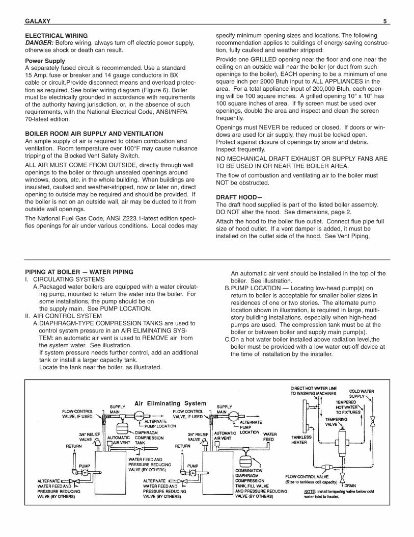
PIPING AT BOILER — WATER PIPINGI. CIRCULATING SYSTEMS
A.Packaged water boilers are equipped with a water circulat-ing pump, mounted to return the water into the boiler. Forsome installations, the pump should be on the supply main. See PUMP LOCATION.
II. AIR CONTROL SYSTEMA.DIAPHRAGM-TYPE COMPRESSION TANKS are used to
control system pressure in an AIR ELIMINATING SYS-TEM: an automatic air vent is used to REMOVE air fromthe system water. See illustration.If system pressure needs further control, add an additionaltank or install a larger capacity tank.Locate the tank near the boiler, as illustrated.
An automatic air vent should be installed in the top of theboiler. See illustration.
B.PUMP LOCATION — Locating low-head pump(s) onreturn to boiler is acceptable for smaller boiler sizes inresidences of one or two stories. The alternate pumplocation shown in illustration, is required in large, multi-story building installations, especially when high-headpumps are used. The compression tank must be at theboiler or between boiler and supply main pump(s).
C.On a hot water boiler installed above radiation level,theboiler must be provided with a low water cut-off device atthe time of installation by the installer.
6 GALAXY
VENT DAMPER INSTALLATION The vent damper referred to in the following instructions is theSlant/Fin Corporation vent damper.I. This device is design certified by C.S.A. for use ONLY on
specific Slant/Fin Corp. gas boiler models. These boilersmust also be equipped with a plate which states that theboiler must or may be used with a Slant/Fin Corp. automaticvent damper device and indicates the proper vent dampermodel number.
II. A.INSTALLATION INSTRUCTIONS BEFORE YOU STARTTO INSTALL1. Read this installation manual, the "DANGER" plate
attached to the top of the boiler, the "WARNING" on thewiring diagrams, vent damper carton and operatorcover.
2. Perform pre-installation inspection as required by ANSIspecification Z21.66.
3. Turn off all electrical power, gas supply and wait for sys-tem to cool (for previously installed boilers).
4. Select a proper, convenient location (see figures 1 & 2).5. Carefully unpack the unit. DO NOT FORCE IT OPEN
OR CLOSED! Forcing the damper may damage thegear train and void the warranty.
WARNING—DANGEROnce you have begun vent damper installation procedure, DONOT restore electric power and gas supply until installation andinspection have been completed (in order to prevent the mainburners from operating). DO NOT operate the boiler until thevent damper harness "RECEPTACLE B" is plugged into "MALEPLUG" (as described in the installation instructions), and thevent damper installation and checkout procedures have beencompleted. Failure to observe this warning may create a haz-ardous condition that could cause an explosion or carbonmonoxide poisoning.
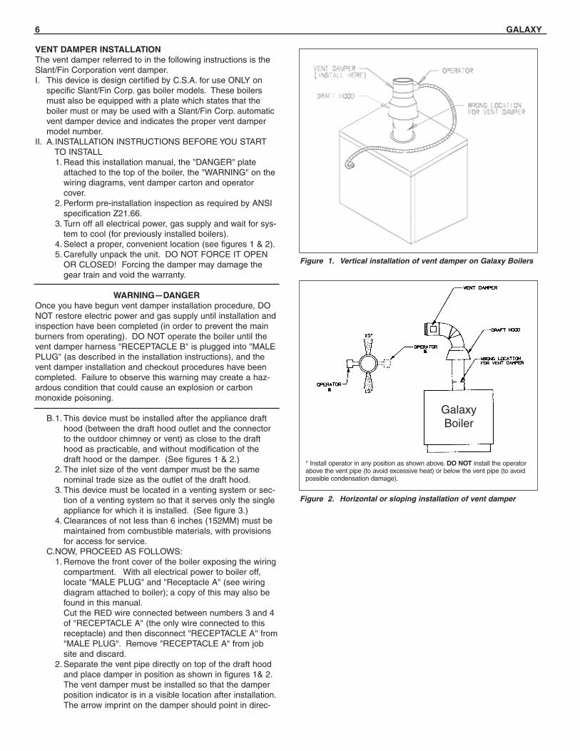
B.1. This device must be installed after the appliance drafthood (between the draft hood outlet and the connectorto the outdoor chimney or vent) as close to the drafthood as practicable, and without modification of thedraft hood or the damper. (See figures 1 & 2.)
2. The inlet size of the vent damper must be the samenominal trade size as the outlet of the draft hood.
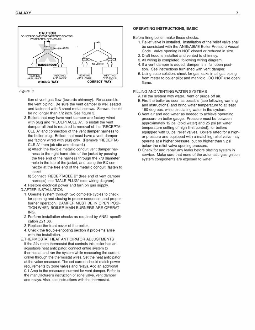
3. This device must be located in a venting system or sec-tion of a venting system so that it serves only the singleappliance for which it is installed. (See figure 3.)
4. Clearances of not less than 6 inches (152MM) must bemaintained from combustible materials, with provisionsfor access for service.
C.NOW, PROCEED AS FOLLOWS:1. Remove the front cover of the boiler exposing the wiring
compartment. With all electrical power to boiler off,locate "MALE PLUG" and "Receptacle A" (see wiringdiagram attached to boiler); a copy of this may also befound in this manual. Cut the RED wire connected between numbers 3 and 4 of "RECEPTACLE A" (the only wire connected to this receptacle) and then disconnect "RECEPTACLE A" from "MALE PLUG". Remove "RECEPTACLE A" from job site and discard.
2. Separate the vent pipe directly on top of the draft hoodand place damper in position as shown in figures 1& 2.The vent damper must be installed so that the damperposition indicator is in a visible location after installation.The arrow imprint on the damper should point in direc-
Figure 1. Vertical installation of vent damper on Galaxy Boilers
Figure 2. Horizontal or sloping installation of vent damper
* Install operator in any position as shown above. DO NOT install the operatorabove the vent pipe (to avoid excessive heat) or below the vent pipe (to avoidpossible condensation damage).
GalaxyBoiler
GALAXY 7
tion of vent gas flow (towards chimney). Re-assemblethe vent piping. Be sure the vent damper is well seatedand fastened with 3 sheet metal screws. Screws shouldbe no longer than 1/2 inch. See figure 3.
3. Boilers that may have vent damper are factory wiredwith plug and "RECEPTACLE A". To install the ventdamper all that is required is removal of the "RECEPTA-CLE A" and connection of the vent damper harness tothe boiler plug. Boilers that must have a vent damperare factory wired with plug only. (Remove "RECEPTA-CLE A" from job site and discard.)a)Attach the flexible metallic conduit vent damper har-
ness to the right hand side of the jacket by passingthe free end of the harness through the 7/8 diameterhole in the top of the jacket, and using the BX con-nector at the free end of the metallic conduit, fasten tojacket.
b)Connect "RECEPTACLE B" (free end of vent damperharness) into "MALE PLUG" (see wiring diagram).
4. Restore electrical power and turn on gas supply.D.AFTER INSTALLATION:
1. Operate system through two complete cycles to checkfor opening and closing in proper sequence, and properburner operation. DAMPER MUST BE IN OPEN POSI-TION WHEN BOILER MAIN BURNERS ARE OPERAT-ING.
2. Perform installation checks as required by ANSI specifi-cation Z21.66.
3. Replace the front cover of the boiler.4. Check the trouble-shooting section if problems arise
with the installation.E.THERMOSTAT HEAT ANTICIPATOR ADJUSTMENTS
If the 24v room thermostat that controls this boiler has an adjustable heat anticipator, connect entire system tothermostat and run the system while measuring the current drawn through the thermostat wires. Set the heat anticipator at the value measured. The set current should match power requirements by zone valves and relays. Add an additional 0.1 Amp to the measured currrent for vent damper. Refer to the manufacturer’s instruction of zone valve, vent damper and relays. Also, see instructions with the thermostat.
Figure 3.
OPERATING INSTRUCTIONS, BASIC
Before firing boiler, make these checks:1. Relief valve is installed. Installation of the relief valve shall
be consistent with the ANSI/ASME Boiler Pressure VesselCode. Valve opening is NOT closed or reduced in size.
2. Draft hood is installed and vented to chimney.3. All wiring is completed, following wiring diagram.4. If a vent damper is added, damper is in full open posi-
tion. See instructions furnished with vent damper.5. Using soap solution, check for gas leaks in all gas piping
from meter to boiler pilot and manifold. DO NOT use openflame.
FILLING AND VENTING WATER SYSTEMSA.Fill the system with water. Vent or purge off air.B.Fire the boiler as soon as possible (see following warning
and instructions) and bring water temperature to at least180 degrees, while circulating water in the system.
C.Vent air and add water as needed to achieve operatingpressure on boiler gauge. Pressure must be betweenapproximately 12 psi (cold water) and 25 psi (at watertemperature setting of high limit control), for boilersequipped with 30 psi relief valves. Boilers rated for a high-er pressure and equipped with a matching relief valve mayoperate at a higher pressure, but no higher than 5 psibelow the relief valve opening pressure.
D.Check for and repair any leaks before placing system inservice. Make sure that none of the automatic gas ignitionsystem components are exposed to water.
8 GALAXY
BURNER ADJUSTMENTA.Adjust gas input rate:
1. Consult gas supplier for heating value of gas (Btu/cu.ft.).2. Set thermostat high enough so that boiler will remain on
while checking rate.3. Measure manifold pressure at 1/8" tapping. Correct
manifold pressure for gas used is printed on boiler rat-ing plate. NOTE: Gas pressure may be adjusted byturning pressure regulator screw on combination gasvalve (Turn clockwise to increase pressure, counterclockwise to decrease pressure).a. Input for PROPANE is approximately at rating shown
on rating plate when manifold pressure is 9-1/2" watercolumn.
b. Input for NATURAL GAS is approximately at ratingwhen manifold pressure is 3-1/2" water column, butshould be checked on the gas meter:Btuh Input = Btuh/cu. ft. x cu. ft. metered in 3 minutes
x 20
SAFETY INFORMATIONFOR YOUR SAFETY READ BEFORE OPERATING
WARNING: If you do not follow these instructionsexactly, a fire or explosion may result causing propertydamage, personal injury or loss of life.
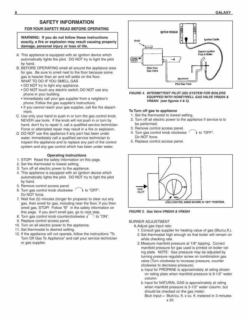
A. This appliance is equipped with an ignition device whichautomatically lights the pilot. DO NOT try to light the pilotby hand.
B. BEFORE OPERATING smell all around the appliance areafor gas. Be sure to smell next to the floor because somegas is heavier than air and will settle on the floor.WHAT TO DO IF YOU SMELL GAS• DO NOT try to light any appliance.• DO NOT touch any electric switch; DO NOT use any
phone in your building.• Immediately call your gas supplier from a neighbor's
phone. Follow the gas supplier's instructions.• If you cannot reach your gas supplier, call the fire depart-
ment.C. Use only your hand to push in or turn the gas control knob.
NEVER use tools. If the knob will not push in or turn byhand, don't try to repair it, call a qualified service technician.Force or attempted repair may result in a fire or explosion.
D. DO NOT use this appliance if any part has been underwater. Immediately call a qualified service technician toinspect the appliance and to replace any part of the controlsystem and any gas control which has been under water.
Operating Instructions1. STOP! Read the safety information on this page.2. Set the thermostat to lowest setting.3. Turn off all electric power to the appliance.4. This appliance is equipped with an ignition device which
automatically lights the pilot. DO NOT try to light the pilotby hand.
5. Remove control access panel. 6. Turn gas control knob clockwise to "OFF".
Do NOT force.7. Wait five (5) minutes (longer for propane) to clear out any
gas, then smell for gas, including near the floor. If you thensmell gas, STOP! Follow "B" in the safety information onthis page. If you don't smell gas, go to next step.
8. Turn gas control knob counterclockwise to "ON".9. Replace control access panel.
10. Turn on all electric power to the appliance.11. Set thermostat to desired setting.12. If the appliance will not operate, follow the instructions "To
Turn Off Gas To Appliance" and call your service technicianor gas supplier.
FIGURE 4. INTERMITTENT PILOT (IID) SYSTEM FOR BOILERSEQUIPPED WITH HONEYWELL GAS VALVE VR8204 &VR8304 (see figures 4 & 5).
FIGURE 5. Gas Valve VR8204 & VR8304
To Turn off gas to appliance1. Set the thermostat to lowest setting.2. Turn off all electric power to the appliance if service is to
be performed.3. Remove control access panel.4. Turn gas control knob clockwise to "OFF".
Do NOT force.5. Replace control access panel.
GALAXY 9
C. Main Burner Ignition Check-out and Pilot Adjustment1. The pilot flame must not smother or snuff out when tested
as follows:a. Main burner ignition from cold start-repeat.b. Continued operation of main burner.c. Main burner ignition with appliance at maximum operating
temperature after prolonged operation.NOTE: Observe operation of the pilot burner with appli-ance doors in the final operating position. Use of a mirrormay be helpful.
2. Safety Shutdown Check-outa. Make certain the pilot burner holds in, and opens properly,
when the pilot is burning normally; and that safety shut-down occurs within 2-1/2 minutes after the pilot flame isextinguished. Observe operation for at least one cycleunder automatic control to be sure the system is function-ing normally.
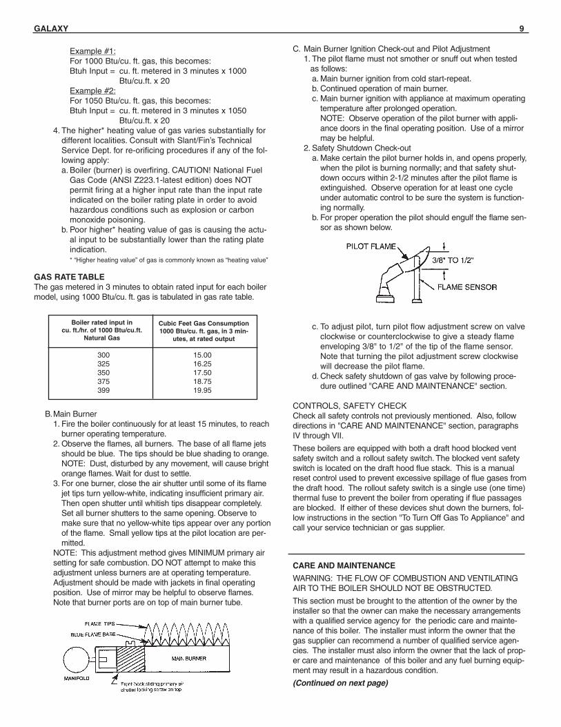
b. For proper operation the pilot should engulf the flame sen-sor as shown below.
c. To adjust pilot, turn pilot flow adjustment screw on valveclockwise or counterclockwise to give a steady flameenveloping 3/8" to 1/2" of the tip of the flame sensor.Note that turning the pilot adjustment screw clockwisewill decrease the pilot flame.
d. Check safety shutdown of gas valve by following proce-dure outlined "CARE AND MAINTENANCE" section.
CONTROLS, SAFETY CHECKCheck all safety controls not previously mentioned. Also, followdirections in "CARE AND MAINTENANCE" section, paragraphsIV through VII.
These boilers are equipped with both a draft hood blocked ventsafety switch and a rollout safety switch. The blocked vent safetyswitch is located on the draft hood flue stack. This is a manualreset control used to prevent excessive spillage of flue gases fromthe draft hood. The rollout safety switch is a single use (one time)thermal fuse to prevent the boiler from operating if flue passagesare blocked. If either of these devices shut down the burners, fol-low instructions in the section "To Turn Off Gas To Appliance" andcall your service technician or gas supplier.
CARE AND MAINTENANCE
WARNING: THE FLOW OF COMBUSTION AND VENTILATINGAIR TO THE BOILER SHOULD NOT BE OBSTRUCTED.
This section must be brought to the attention of the owner by theinstaller so that the owner can make the necessary arrangementswith a qualified service agency for the periodic care and mainte-nance of this boiler. The installer must inform the owner that thegas supplier can recommend a number of qualified service agen-cies. The installer must also inform the owner that the lack of prop-er care and maintenance of this boiler and any fuel burning equip-ment may result in a hazardous condition.
(Continued on next page)
300 15.00325 16.25350 17.50375 18.75399 19.95
Boiler rated input incu. ft./hr. of 1000 Btu/cu.ft.
Natural Gas
Cubic Feet Gas Consumption1000 Btu/cu. ft. gas, in 3 min-
utes, at rated output
B.Main Burner1. Fire the boiler continuously for at least 15 minutes, to reach
burner operating temperature.2. Observe the flames, all burners. The base of all flame jets
should be blue. The tips should be blue shading to orange.NOTE: Dust, disturbed by any movement, will cause brightorange flames. Wait for dust to settle.
3. For one burner, close the air shutter until some of its flamejet tips turn yellow-white, indicating insufficient primary air.Then open shutter until whitish tips disappear completely.Set all burner shutters to the same opening. Observe tomake sure that no yellow-white tips appear over any portionof the flame. Small yellow tips at the pilot location are per-mitted.
NOTE: This adjustment method gives MINIMUM primary airsetting for safe combustion. DO NOT attempt to make thisadjustment unless burners are at operating temperature.Adjustment should be made with jackets in final operatingposition. Use of mirror may be helpful to observe flames.Note that burner ports are on top of main burner tube.
Example #1:For 1000 Btu/cu. ft. gas, this becomes:Btuh Input = cu. ft. metered in 3 minutes x 1000
Btu/cu.ft. x 20 Example #2:For 1050 Btu/cu. ft. gas, this becomes:Btuh Input = cu. ft. metered in 3 minutes x 1050
Btu/cu.ft. x 20 4. The higher* heating value of gas varies substantially for
different localities. Consult with Slant/Fin’s TechnicalService Dept. for re-orificing procedures if any of the fol-lowing apply:a. Boiler (burner) is overfiring. CAUTION! National Fuel
Gas Code (ANSI Z223.1-latest edition) does NOTpermit firing at a higher input rate than the input rateindicated on the boiler rating plate in order to avoidhazardous conditions such as explosion or carbonmonoxide poisoning.
b. Poor higher* heating value of gas is causing the actu-al input to be substantially lower than the rating plateindication.* “Higher heating value” of gas is commonly known as “heating value”
GAS RATE TABLEThe gas metered in 3 minutes to obtain rated input for each boilermodel, using 1000 Btu/cu. ft. gas is tabulated in gas rate table.
10 GALAXY
I. GENERAL MAINTENANCE These operations are recommended to be performed at regularintervals:A.BOILER HEATING SURFACES: clean off all coatings found.B.BOILER CONTROLS: check contacts, settings, correct func-
tioning.C.PIPING: check piping and accessories for leaks.D.CHIMNEY and BREECHING: check for obstructions and
leaks.E.BOILER ROOM AIR SUPPLY: check air vents for continued
POSITIVE supply of air as required. Air needs are greatest incold weather. Air vents must be open and free of obstruction.
F. WATER SYSTEM: check1. System to be full of water, and pressure to remain stable at
correct setting on gauge.2. Air-control system: noise and air binding in radiation should
not occur.3. Water lines: slightest leaks should be corrected.4. Low water cut-off, for operation (see instructions furnished
with unit.)
II. WATER LEVEL CHECK DURING HEATING SEASON:Regular loss of water from water boiler system may indicate either a system leak, or a faulty air-control system, or a faulty automatic fill valve.
III. ANNUAL INSPECTION AND CLEANING:A.It is important that this boiler be inspected by a competent
serviceperson to help insure safe and reliable operation.B.Check for gas leaks from valve and gas piping to burners and
pilot. If leaks are found, repair or replace as required.C.This inspection should include:
1. Controls check. See SAFETY CHECK, IV.2. Recheck of input gas rate to burners. See "Initial Start"
paragraph in "Operating Instructions" section.3. Re-adjusting for best flame characteristics of main flame
and pilot.See "Initial Start" paragraph in "Operating Instructions" sec-tion and see "Burner Adjustment" section.
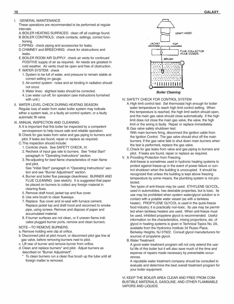
4. Burner and boiler flue passage cleanliness: BURNER ANDFLUE CLEANING (see sketch). It is suggested that paperbe placed on burners to collect any foreign material incleaning flues.
5. Remove draft hood, jacket top and flue cover.6. Use wire brush to clean flueways.7. Replace flue cover and re-seal with furnace cement.
Replace jacket top and draft hood and reconnect to smokepipe, using screws. Remove and dispose of paper andaccumulated material.
8. If burner surfaces are not clean, or if uneven flame indi-cates plugged burner ports, remove and clean burners.
NOTE—TO REMOVE BURNERS:a. Remove holding wire clip at orifice.b. Disconnect pilot at pilot mount, or disconnect pilot gas line at
gas valve, before removing burners next to pilot.c. Lift rear of burner and remove burner from orifice. d. Clean and replace burners* and pilot. Adjust burners as
described on “Burner Adjustment”.* To clean burners run a clean flue brush up the tube until all
foreign matter is removed.
Boiler Cleaning
IV. SAFETY CHECK FOR CONTROL SYSTEMA.High limit control test: Set thermostat high enough for boiler
water temperature to reach high limit control setting. Whenthis temperature is reached, the high limit switch should open,and the main gas valve should close automatically. If the highlimit does not close the main gas valve, the valve, the highlimit or the wiring is faulty. Repair or replace immediately.
B.Gas valve safety shutdown test:With main burners firing, disconnect the ignition cable from the Ignition Control. The gas valve should shut off the main burners. If the gas valve fails to shut down main burners whenthe test is performed, replace the gas valve.
C.Check for gas leaks from valve and gas piping to burners andpilot. If leaks are found, repair or replace as required.
V. A.Providing Protection from Freezing.Anti-freeze is sometimes used in hydronic heating systems toprotect against freeze-up in the event of power failure or con-trol shutdown when the building is unoccupied. It should berecognized that unless the building is kept above freezingtemperature by some means, the plumbing system is not pro-tected.Two types of anti-freeze may be used: ETHYLENE GLYCOL,used in automobiles, has desirable properties, but is toxic. Itsuse may be prohibited when system water/glycol solution is incontact with a potable water vessel (as with a tanklessheater). PROPYLENE GLYCOL is used in the quick-freezefood industry; it is practically non-toxic. Its use may be permit-ted when tankless heaters are used. When anti-freeze mustbe used, inhibited propylene glycol is recommended. Usefulinformation on the characteristics, mixing proportions, etc. ofglycol in heating systems is given in Technical Topics No. 2A,available from the Hydronics Institute 34 Russo Place,Berkeley Heights, NJ 07922. Consult glycol manufacturers forsources of propylene glycol.
B.Water Treatment:A good water treatment program will not only extend the use-ful life of this boiler but it will also save much of the time andexpense of repairs made necessary by preventable occur-rences.A reputable water treatment company should be consulted toevaluate and determine the best overall treatment program foryour boiler equipment.
VI. KEEP THE BOILER AREA CLEAR AND FREE FROM COM-BUSTIBLE MATERIALS, GASOLINE, AND OTHER FLAMMABLEVAPORS AND LIQUIDS.
GALAXY 11
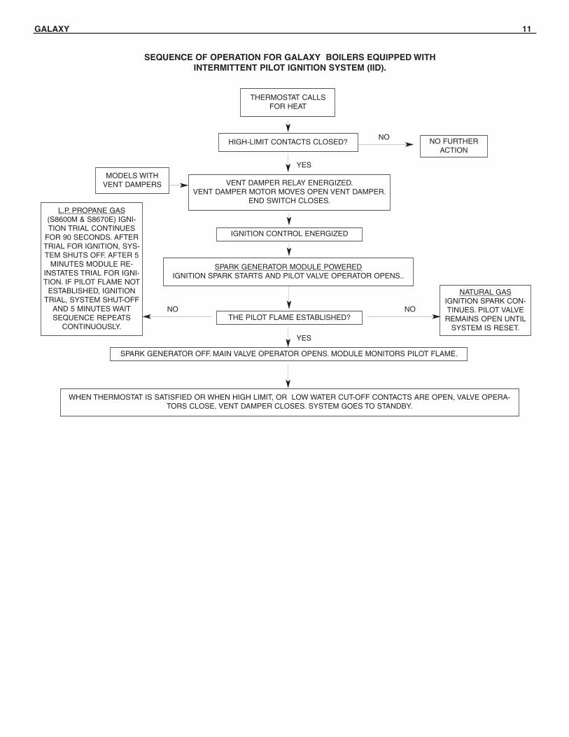
SEQUENCE OF OPERATION FOR GALAXY BOILERS EQUIPPED WITHINTERMITTENT PILOT IGNITION SYSTEM (IID).
HIGH-LIMIT CONTACTS CLOSED?
VENT DAMPER RELAY ENERGIZED.VENT DAMPER MOTOR MOVES OPEN VENT DAMPER.
END SWITCH CLOSES.
IGNITION CONTROL ENERGIZED
SPARK GENERATOR MODULE POWEREDIGNITION SPARK STARTS AND PILOT VALVE OPERATOR OPENS..
L.P. PROPANE GAS(S8600M & S8670E) IGNI-TION TRIAL CONTINUES
FOR 90 SECONDS. AFTERTRIAL FOR IGNITION, SYS-TEM SHUTS OFF. AFTER 5
MINUTES MODULE RE-INSTATES TRIAL FOR IGNI-TION. IF PILOT FLAME NOT
ESTABLISHED, IGNITIONTRIAL, SYSTEM SHUT-OFF
AND 5 MINUTES WAITSEQUENCE REPEATS
CONTINUOUSLY.
NATURAL GASIGNITION SPARK CON-TINUES. PILOT VALVE
REMAINS OPEN UNTILSYSTEM IS RESET.
SPARK GENERATOR OFF. MAIN VALVE OPERATOR OPENS. MODULE MONITORS PILOT FLAME.
THERMOSTAT CALLSFOR HEAT
MODELS WITHVENT DAMPERS
THE PILOT FLAME ESTABLISHED?
WHEN THERMOSTAT IS SATISFIED OR WHEN HIGH LIMIT, OR LOW WATER CUT-OFF CONTACTS ARE OPEN, VALVE OPERA-TORS CLOSE, VENT DAMPER CLOSES. SYSTEM GOES TO STANDBY.
NO FURTHERACTION
NO
NONO
YES
YES
12 GALAXY
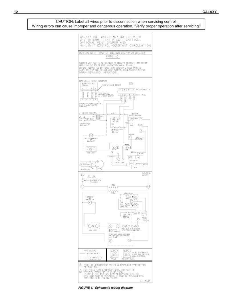
CAUTION: Label all wires prior to disconnection when servicing control.Wiring errors can cause improper and dangerous operation. “Verify proper operation after servicing.”
FIGURE 6. Schematic wiring diagram
GALAXY 13
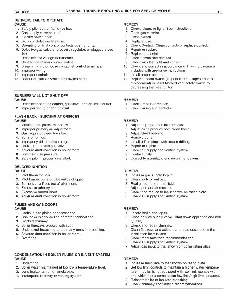
BURNERS FAIL TO OPERATECAUSE1. Safety pilot out, or flame too low.2. Gas supply valve shut off.3. Electric switch open.4. Blown or defective line fuse.5. Operating or limit control contacts open or dirty.6. Defective gas valve or pressure regulator; or plugged bleed
line.7. Defective low voltage transformer.8. Obstruction at main burner orifice.9. Break in wiring or loose contact at control terminals.
10. Improper wiring.11. Improper controls.12. Rollout or blocked vent safety switch open.
BURNERS WILL NOT SHUT OFFCAUSE1. Defective operating control, gas valve, or high limit control.2. Improper wiring or short circuit.
FLASH BACK - BURNING AT ORIFICESCAUSE1. Manifold gas pressure too low.2. Improper primary air adjustment.3. Gas regulator bleed too slow.4. Burrs on orifice.5. Improperly drilled orifice plugs.6. Leaking automatic gas valve.7. Adverse draft condition in boiler room.8. Low main gas pressure.9. Safety pilot improperly installed.
DELAYED IGNITIONCAUSE1. Pilot flame too low.2. Pilot burner ports or pilot orifice clogged.3. Burners or orifices out of alignment.4. Excessive primary air.5. Excessive burner input.6. Adverse draft condition in boiler room.
FUMES AND GAS ODORSCAUSE1. Leaks in gas piping or accessories.2. Gas leaks in service line or meter connections.3. Blocked chimney.4. Boiler flueways blocked with soot.5. Undersized breeching or too many turns in breeching.6. Adverse draft condition in boiler room.7. Overfiring.
CONDENSATION IN BOILER FLUES OR IN VENT SYSTEMCAUSE1. Underfiring.2. Boiler water maintained at too low a temperature level.3. Long horizontal run of smokepipe.4. Inadequate chimney or venting system.
REMEDY1. Check, clean, re-light. See instructions.2. Open gas valve(s).3. Close Switch.4. Replace fuse.5. Check Control. Clean contacts or replace control.6. Repair or replace.7. Replace aquastat.8. Check, clean and reinstall.9. Check with test-light and correct.
10. Check and correct in accordance with wiring diagramsincluded with appliance instructions.
11. Install proper controls.12. Replace rollout switch (inspect flue passages prior to
replacement) or reset blocked vent safety switch bydepressing the reset button
REMEDY1. Check, repair or replace.2. Check wiring and controls.
REMEDY1. Adjust to proper manifold pressure.2. Adjust air to produce soft, clean flame.3. Adjust bleed opening.4. Remove burrs.5. Install orifice plugs with proper drilling.6. Repair or replace.7. Check air supply and venting system.8. Contact utility.9. Correct to manufacturer's recommendations.
REMEDY1. Increase gas supply to pilot.2. Clean ports or orifices.3. Realign burners or manifold.4. Adjust primary air shutters.5. Check and reduce to input shown on rating plate.6. Check air supply and venting system.
REMEDY1. Locate leaks and repair.2. Close service supply valve - shut down appliance and noti-
fy utility.3. Check and repair chimney.4. Clean flueways and adjust burners as described in the
installation instructions.5. Check manufacturer's recommendations.6. Check air supply and venting system.7. Adjust gas input to that shown on boiler rating plate.
REMEDY1. Increase firing rate to that shown on rating plate.2. Set low limit controls to maintain a higher water tempera-
ture. If boiler is not equipped with low limit replace withone which has a combination low limit/high limit aquastat.
3. Relocate boiler or insulate breeching.4. Check chimney and venting recommendations.
GENERAL TROUBLE SHOOTING GUIDE FOR SERVICEPEOPLE
14 GALAXY
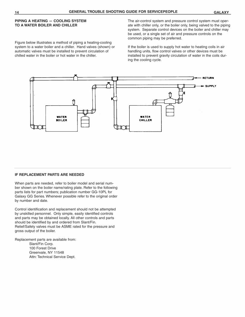
PIPING A HEATING — COOLING SYSTEMTO A WATER BOILER AND CHILLER
Figure below illustrates a method of piping a heating-coolingsystem to a water boiler and a chiller. Hand valves (shown) orautomatic valves must be installed to prevent circulation ofchilled water in the boiler or hot water in the chiller.
IF REPLACEMENT PARTS ARE NEEDED
When parts are needed, refer to boiler model and serial num-ber shown on the boiler name/rating plate. Refer to the followingparts lists for part numbers; publication number GG-10PL forGalaxy GG Series. Whenever possible refer to the original orderby number and date.
Control identification and replacement should not be attemptedby unskilled personnel. Only simple, easily identified controlsand parts may be obtained locally. All other controls and partsshould be identified by and ordered from Slant/Fin.Relief/Safety valves must be ASME rated for the pressure andgross output of the boiler.
Replacement parts are available from:Slant/Fin Corp.100 Forest DriveGreenvale, NY 11548Attn: Technical Service Dept.
The air-control system and pressure control system must oper-ate with chiller only, or the boiler only, being valved to the pipingsystem. Separate control devices on the boiler and chiller maybe used, or a single set of air and pressure controls on thecommon piping may be preferred.
If the boiler is used to supply hot water to heating coils in airhandling units, flow control valves or other devices must beinstalled to prevent gravity circulation of water in the coils dur-ing the cooling cycle.
GENERAL TROUBLE SHOOTING GUIDE FOR SERVICEPEOPLE
GALAXY 15
APPENDIX A
Removal of Existing Boiler from Common Vent System
"At the time of removal of an existing boiler, the following steps shall be followed with each appliance remaining connected to the com-mon venting system placed in operation, while the other appliances remaining connected to the common venting system are not inoperation."
(a) Seal any unused openings in the common venting system.
(b) Visually inspect the venting system for proper size and hori-zontal pitch and determine there is no blockage or restric-tion, leakage, corrosion and other deficiencies which couldcause an unsafe condition.
(c) Insofar as is practical, close all building doors and windowsand all doors between the space in which the appliancesremaining connected to the common venting system arelocated and other spaces of the building. Turn on clothesdryers and any appliance not connected to the commonventing system. Turn on any exhaust fans, such as rangehoods and bathroom exhausts, so they will operate at maxi-mum speed. DO NOT operate a summer exhaust fan.Close fireplace dampers.
(d) Place in operation the appliance being inspected. Followthe lighting instructions. Adjust thermostat so appliance willoperate continuously.
(e) Test for spillage at the draft hood relief opening after 5 min-
utes of main burner operation. Use the flame of a match orcandle, or smoke from a cigarette, cigar or pipe.
(f) After it has been determined that each appliance remainingconnected to the common venting system properly ventswhen tested as outlined above, return doors, windows,exhaust fans, fireplace dampers and any other gas-burningappliance to their previous conditions of use."
(g) Any improper operation of the common venting systemshould be corrected so the installation conforms with theNational Fuel Gas Code, ANSI Z223.1-latest edition. Whenresizing any portion of the common venting system, thecommon venting system should be resized to approach theminimum size as determined using the appropriate tables inAppendix G in the National Fuel Gas Code, ANSI Z223.1-latest edition.

©Slant/Fin Corp. 2016 • Printed in U.S.A. 516 • Publication GG-40S
U.S.A.Slant/Fin Corporation • 100 Forest DriveGreenvale, NY 11548 • 516-484-0933www.slantfin.com
CanadaSlant/Fin LTD/LTEE • 400 Ambassador Drive,Mississauga, Ontario L5T 2 J3 • 905-677-8400www.slantfin.ca


![GAS-FIRED STEAM BOILERS · GAS-FIRED STEAM BOILERS INSTALLATION, OPERATION & MAINTENANCE MANUAL P/N# 240009572, Rev. B [07/2012] MODEL PEGDID Electronic Intermittent Ignition An ISO](https://img.pdfslide.us/doc/110x75/5d5f2dac88c993e3528b930c/gas-fired-steam-boilers-gas-fired-steam-boilers-installation-operation-maintenance.jpg)


![Installation & Maintenance Manualurbanfp.ca/.../2015/11/H-Series-Installation-Manual.pdf · · 2016-10-20Improper installation, adjustment, ... [Intermittent Pilot Ignition] Jumper](https://img.pdfslide.us/doc/110x75/5aa5409a7f8b9a517d8cf9fd/installation-maintenance-installation-adjustment-intermittent-pilot-ignition.jpg)
![Installation & Maintenance Manual - Urban Fireplaces installation, adjustment, ... [Intermittent Pilot Ignition] Jumper Cable Installation ... frequent cleaning may be required due](https://img.pdfslide.us/doc/110x75/5aa534887f8b9ab4788cd955/installation-maintenance-manual-urban-fireplaces-installation-adjustment-.jpg)