Embed Size (px)
Citation preview
3C3-28199-11
FZS10WFZS10WC
OWNER’S MANUAL
LIT-11626-20-54
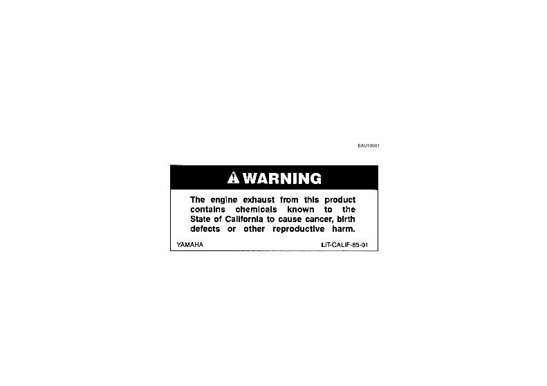
EAU10041
U3C311E0.book Page 1 Monday, September 11, 2006 1:18 PM
INTRODUCTIONEAU10080
Congratulations on your purchase of the Yamaha FZS10W/FZS10WC. This model is the result of Yamaha’s vast experiencein the production of fine sporting, touring, and pacesetting racing machines. It represents the high degree of craftsmanshipand reliability that have made Yamaha a leader in these fields.This manual will give you an understanding of the operation, inspection, and basic maintenance of this motorcycle. If youhave any questions concerning the operation or maintenance of your motorcycle, please consult a Yamaha dealer.The design and manufacture of this Yamaha motorcycle fully comply with the emissions standards for clean air applicable atthe date of manufacture. Yamaha has met these standards without reducing the performance or economy of operation of themotorcycle. To maintain these high standards, it is important that you and your Yamaha dealer pay close attention to therecommended maintenance schedules and operating instructions contained within this manual.
U3C311E0.book Page 1 Monday, September 11, 2006 1:18 PM
IMPORTANT MANUAL INFORMATIONEAU10131
Particularly important information is distinguished in this manual by the following notations:
NOTE:� This manual should be considered a permanent part of this motorcycle and should remain with it even if the motorcycle
is subsequently sold.� Yamaha continually seeks advancements in product design and quality. Therefore, while this manual contains the most
current product information available at the time of printing, there may be minor discrepancies between your motorcycleand this manual. If you have any questions concerning this manual, please consult your Yamaha dealer.
WARNINGEWA10010
PLEASE READ THIS MANUAL AND THE “YOU AND YOUR MOTORCYCLE: RIDING TIPS” BOOKLET CAREFULLYAND COMPLETELY BEFORE OPERATING THIS MOTORCYCLE. DO NOT ATTEMPT TO OPERATE THIS MOTOR-CYCLE UNTIL YOU HAVE ATTAINED ADEQUATE KNOWLEDGE OF ITS CONTROLS AND OPERATING FEATURES
The Safety Alert Symbol means ATTENTION! BECOME ALERT! YOUR SAFETY IS INVOLVED!
Failure to follow WARNING instructions could result in severe injury or death to the motorcycle operator, a bystander or a person inspecting or repairing the motor-cycle.
A CAUTION indicates special precautions that must be taken to avoid damage to the motorcycle.
A NOTE provides key information to make procedures easier or clearer.
WARNING
CAUTION:
NOTE:
U3C311E0.book Page 1 Monday, September 11, 2006 1:18 PM
IMPORTANT MANUAL INFORMATIONAND UNTIL YOU HAVE BEEN TRAINED IN SAFE AND PROPER RIDING TECHNIQUES. REGULAR INSPECTIONSAND CAREFUL MAINTENANCE, ALONG WITH GOOD RIDING SKILLS, WILL ENSURE THAT YOU SAFELY ENJOYTHE CAPABILITIES AND THE RELIABILITY OF THIS MOTORCYCLE.
*Product and specifications are subject to change without notice.
U3C311E0.book Page 2 Monday, September 11, 2006 1:18 PM
IMPORTANT MANUAL INFORMATION
EAU10192
FZS10W/FZS10WCOWNER’S MANUAL
©2006 by Yamaha Motor Corporation, U.S.A.1st edition, September 2006
All rights reserved.Any reprinting or unauthorized use without the written permission of Yamaha Motor Corporation, U.S.A.
is expressly prohibited.Printed in Japan.
P/N LIT-11626-20-54
AFFIX DEALER
LABEL HERE
U3C311E0.book Page 3 Monday, September 11, 2006 1:18 PM
TABLE OF CONTENTSSAFETY INFORMATION ..................1-1
Location of important labels ...........1-5
DESCRIPTION ..................................2-1Left view ..........................................2-1Right view........................................2-2Controls and instruments ................2-3
INSTRUMENT AND CONTROL FUNCTIONS .......................................3-1
Main switch/steering lock ................3-1Indicator and warning lights ............3-2Multi-function meter unit .................3-4Handlebar switches ........................3-8Clutch lever ....................................3-9Shift pedal ......................................3-9Brake lever ...................................3-10Brake pedal ..................................3-10Fuel tank cap ................................3-10Fuel ..............................................3-11Catalytic converter ........................3-12Seats ............................................3-12Storage compartment ...................3-14Adjusting the front fork .................3-14Adjusting the shock absorber
assembly ...................................3-16Luggage strap holders ..................3-18EXUP system ...............................3-18Sidestand .....................................3-18Ignition circuit cut-off system ........3-19
PRE-OPERATION CHECKS ............. 4-1Pre-operation check list ................. 4-2
OPERATION AND IMPORTANT RIDING POINTS ................................ 5-1
Starting the engine ......................... 5-1Shifting ........................................... 5-2Engine break-in .............................. 5-4Parking ........................................... 5-4
PERIODIC MAINTENANCE AND MINOR REPAIR................................. 6-1
PERIODIC MAINTENANCE .......... 6-1Owner’s tool kit .............................. 6-1Periodic maintenance chart for the
emission control system ............. 6-3General maintenance and
lubrication chart .......................... 6-4Removing and installing panels ..... 6-8Checking the spark plugs .............. 6-9Canister (for California only) ........ 6-10Engine oil and oil filter cartridge ... 6-10Coolant ........................................ 6-13Replacing the air filter element .... 6-15Checking the throttle cable free
play ........................................... 6-17Valve clearance ........................... 6-17Tires ............................................. 6-17Cast wheels ................................. 6-20Accessories and replacement
parts ......................................... 6-20
Adjusting the clutch lever free play ........................................... 6-21
Adjusting the rear brake light switch ........................................6-22
Checking the front and rear brake pads ................................ 6-22
Checking the brake fluid level ...... 6-23Changing the brake fluid .............. 6-24Drive chain slack .......................... 6-24Cleaning and lubricating the
drive chain ................................ 6-25Checking and lubricating the
cables ....................................... 6-26Checking and lubricating the
throttle grip and cable ............... 6-26Checking and lubricating the
brake and shift pedals ............... 6-27Checking and lubricating the
brake and clutch levers .............6-27Checking and lubricating the
centerstand and sidestand ........6-28Checking the front fork ................. 6-28Checking the steering ..................6-29Checking the wheel bearings .......6-30Battery .......................................... 6-30Replacing the fuses ...................... 6-31Replacing a headlight bulb ........... 6-33Replacing the tail/brake light
bulb ........................................... 6-34Replacing a turn signal light
bulb ........................................... 6-35
U3C311E0.book Page 1 Monday, September 11, 2006 1:18 PM
TABLE OF CONTENTSReplacing the license plate light
bulb ...........................................6-36Front wheel ...................................6-36Rear wheel ...................................6-38Troubleshooting ............................6-39Troubleshooting charts .................6-40
MOTORCYCLE CARE AND STORAGE ..........................................7-1
Matte color caution .........................7-1Care ................................................7-1Storage ...........................................7-3
SPECIFICATIONS .............................8-1
CONSUMER INFORMATION.............9-1Identification numbers ....................9-1Reporting safety defects .................9-3Motorcycle noise regulation ............9-4Maintenance record ........................9-5YAMAHA MOTOR CORPORATION,
U.S.A. STREET AND ENDURO MOTORCYCLE LIMITED WARRANTY ................................9-7
YAMAHA EXTENDED SERVICE (Y.E.S.) ........................................9-9
U3C311E0.book Page 2 Monday, September 11, 2006 1:18 PM
1-1
1
SAFETY INFORMATIONEAU10281
MOTORCYCLES ARE SINGLETRACK VEHICLES. THEIR SAFE USEAND OPERATION ARE DEPENDENTUPON THE USE OF PROPER RIDINGTECHNIQUES AS WELL AS THE EX-PERTISE OF THE OPERATOR. EV-ERY OPERATOR SHOULD KNOWTHE FOLLOWING REQUIREMENTSBEFORE RIDING THIS MOTOR-CYCLE.HE OR SHE SHOULD:
� OBTAIN THOROUGH INSTRUC-TIONS FROM A COMPETENTSOURCE ON ALL ASPECTS OFMOTORCYCLE OPERATION.
� OBSERVE THE WARNINGS ANDMAINTENANCE REQUIRE-MENTS IN THE OWNER’S MAN-UAL.
� OBTAIN QUALIFIED TRAININGIN SAFE AND PROPER RIDINGTECHNIQUES.
� OBTAIN PROFESSIONAL TECH-NICAL SERVICE AS INDICATEDBY THE OWNER’S MANUAL
AND/OR WHEN MADE NECES-SARY BY MECHANICAL CONDI-TIONS.
Safe riding� Always make pre-operation
checks. Careful checks may helpprevent an accident.
� This motorcycle is designed to car-ry the operator and a passenger.
� The failure of motorists to detectand recognize motorcycles in traf-fic is the predominating cause ofautomobile/motorcycle accidents.Many accidents have been causedby an automobile driver who didnot see the motorcycle. Makingyourself conspicuous appears tobe very effective in reducing thechance of this type of accident.Therefore:• Wear a brightly colored jacket.• Use extra caution when you are
approaching and passingthrough intersections, since in-tersections are the most likelyplaces for motorcycle accidentsto occur.
• Ride where other motorists cansee you. Avoid riding in anothermotorist’s blind spot.
� Many accidents involve inexperi-enced operators. In fact, many op-erators who have been involved inaccidents do not even have a cur-rent motorcycle license.• Make sure that you are qualified
and that you only lend yourmotorcycle to other qualified op-erators.
• Know your skills and limits.Staying within your limits mayhelp you to avoid an accident.
• We recommend that you prac-tice riding your motorcyclewhere there is no traffic until youhave become thoroughly famil-iar with the motorcycle and all ofits controls.
� Many accidents have been causedby error of the motorcycle opera-tor. A typical error made by the op-erator is veering wide on a turn
U3C311E0.book Page 1 Monday, September 11, 2006 1:18 PM
SAFETY INFORMATION
1-2
1
due to EXCESSIVE SPEED or un-dercornering (insufficient lean an-gle for the speed).• Always obey the speed limit and
never travel faster than warrant-ed by road and traffic conditions.
• Always signal before turning orchanging lanes. Make sure thatother motorists can see you.
� The posture of the operator andpassenger is important for propercontrol.• The operator should keep both
hands on the handlebar andboth feet on the operator foot-rests during operation to main-tain control of the motorcycle.
• The passenger should alwayshold onto the operator, the seatstrap or grab bar, if equipped,with both hands and keep bothfeet on the passenger footrests.
• Never carry a passenger unlesshe or she can firmly place bothfeet on the passenger footrests.
� Never ride under the influence ofalcohol or other drugs.
� This motorcycle is designed for on-road use only. It is not suitable foroff-road use.
Protective apparelThe majority of fatalities from motor-cycle accidents are the result of headinjuries. The use of a safety helmet isthe single most critical factor in the pre-vention or reduction of head injuries.
� Always wear an approved helmet.� Wear a face shield or goggles.
Wind in your unprotected eyescould contribute to an impairmentof vision that could delay seeing ahazard.
� The use of a jacket, heavy boots,trousers, gloves, etc., is effective inpreventing or reducing abrasionsor lacerations.
� Never wear loose-fitting clothes,otherwise they could catch on thecontrol levers, footrests, or wheelsand cause injury or an accident.
� Never touch the engine or exhaustsystem during or after operation.They become very hot and can
cause burns. Always wear protec-tive clothing that covers your legs,ankles, and feet.
� A passenger should also observethe above precautions.
ModificationsModifications made to this motorcyclenot approved by Yamaha, or the re-moval of original equipment, may ren-der the motorcycle unsafe for use andmay cause severe personal injury.Modifications may also make yourmotorcycle illegal to use.
Loading and accessoriesAdding accessories or cargo to yourmotorcycle can adversely affect stabili-ty and handling if the weight distributionof the motorcycle is changed. To avoidthe possibility of an accident, use ex-treme caution when adding cargo oraccessories to your motorcycle. Useextra care when riding a motorcyclethat has added cargo or accessories.Here are some general guidelines tofollow if loading cargo or adding acces-sories to your motorcycle:
U3C311E0.book Page 2 Monday, September 11, 2006 1:18 PM
SAFETY INFORMATION
1-3
1
LoadingThe total weight of the operator, pas-senger, accessories and cargo mustnot exceed the maximum load limit.
When loading within this weight limit,keep the following in mind:
� Cargo and accessory weightshould be kept as low and close tothe motorcycle as possible. Makesure to distribute the weight asevenly as possible on both sides ofthe motorcycle to minimize imbal-ance or instability.
� Shifting weights can create a sud-den imbalance. Make sure that ac-cessories and cargo are securelyattached to the motorcycle beforeriding. Check accessory mountsand cargo restraints frequently.
� Never attach any large or heavyitems to the handlebar, front fork,or front fender. These items, in-cluding such cargo as sleeping
bags, duffel bags, or tents, cancreate unstable handling or a slowsteering response.
AccessoriesGenuine Yamaha accessories havebeen specifically designed for use onthis motorcycle. Since Yamaha cannottest all other accessories that may beavailable, you must personally be re-sponsible for the proper selection, in-stallation and use of non-Yamahaaccessories. Use extreme cautionwhen selecting and installing any ac-cessories.Keep the following guidelines in mind,as well as those provided under “Load-ing” when mounting accessories.
� Never install accessories or carrycargo that would impair the perfor-mance of your motorcycle. Care-fully inspect the accessory beforeusing it to make sure that it doesnot in any way reduce groundclearance or cornering clearance,
limit suspension travel, steeringtravel or control operation, or ob-scure lights or reflectors.• Accessories fitted to the handle-
bar or the front fork area cancreate instability due to improperweight distribution or aerody-namic changes. If accessoriesare added to the handlebar orfront fork area, they must be aslightweight as possible andshould be kept to a minimum.
• Bulky or large accessories mayseriously affect the stability ofthe motorcycle due to aerody-namic effects. Wind may at-tempt to lift the motorcycle, orthe motorcycle may become un-stable in cross winds. These ac-cessories may also causeinstability when passing or beingpassed by large vehicles.
• Certain accessories can dis-place the operator from his orher normal riding position. Thisimproper position limits the free-dom of movement of the opera-
Maximum load:189 kg (417 lb) (CAL)190 kg (419 lb) (U49)
U3C311E0.book Page 3 Monday, September 11, 2006 1:18 PM
SAFETY INFORMATION
1-4
1
tor and may limit control ability,therefore, such accessories arenot recommended.
� Use caution when adding electri-cal accessories. If electrical acces-sories exceed the capacity of themotorcycle’s electrical system, anelectric failure could result, whichcould cause a dangerous loss oflights or engine power.
Gasoline and exhaust gas� GASOLINE IS HIGHLY FLAMMA-
BLE:• Always turn the engine off when
refueling.• Take care not to spill any gaso-
line on the engine or exhaustsystem when refueling.
• Never refuel while smoking or inthe vicinity of an open flame.
� Never start the engine or let it runfor any length of time in a closedarea. The exhaust fumes are poi-sonous and may cause loss ofconsciousness and death within ashort time. Always operate yourmotorcycle in an area that has ad-equate ventilation.
� Always turn the engine off beforeleaving the motorcycle unattendedand remove the key from the mainswitch. When parking the motor-cycle, note the following:• The engine and exhaust system
may be hot, therefore, park themotorcycle in a place where pe-destrians or children are not like-ly to touch these hot areas.
• Do not park the motorcycle on aslope or soft ground, otherwise itmay fall over.
• Do not park the motorcycle neara flammable source, (e.g., a ker-osene heater, or near an openflame), otherwise it could catchfire.
� When transporting the motorcyclein another vehicle, make sure thatit is kept upright. If the motorcycleshould lean over, gasoline mayleak out of the fuel tank.
� If you should swallow any gaso-line, inhale a lot of gasoline vapor,or allow gasoline to get into youreyes, see your doctor immediately.If any gasoline spills on your skin
or clothing, immediately wash theaffected area with soap and waterand change your clothes.
U3C311E0.book Page 4 Monday, September 11, 2006 1:18 PM
SAFETY INFORMATION
1-5
1
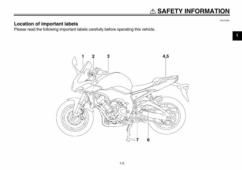
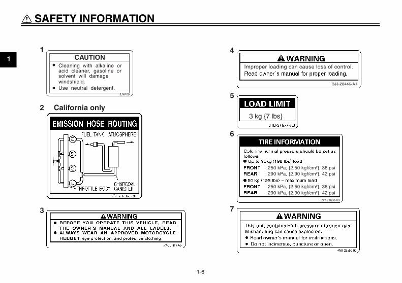
EAU10381
Location of important labels Please read the following important labels carefully before operating this vehicle.
U3C311E0.book Page 5 Monday, September 11, 2006 1:18 PM
SAFETY INFORMATION
1-6
11
3
2
5
4
6
7
CAUTIONCleaning with alkaline oracid cleaner, gasoline orsolvent will damagewindshield.Use neutral detergent.
5JW-00
California only
U3C311E0.book Page 6 Monday, September 11, 2006 1:18 PM
DESCRIPTION
2-1
2
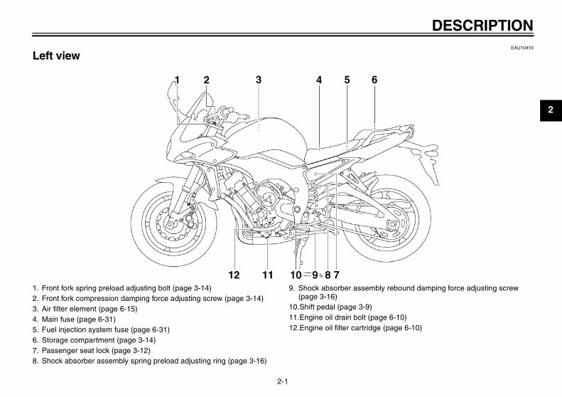
EAU10410
Left view
1. Front fork spring preload adjusting bolt (page 3-14)2. Front fork compression damping force adjusting screw (page 3-14)3. Air filter element (page 6-15)4. Main fuse (page 6-31)5. Fuel injection system fuse (page 6-31)6. Storage compartment (page 3-14)7. Passenger seat lock (page 3-12)8. Shock absorber assembly spring preload adjusting ring (page 3-16)
9. Shock absorber assembly rebound damping force adjusting screw (page 3-16)
10.Shift pedal (page 3-9)11.Engine oil drain bolt (page 6-10)12.Engine oil filter cartridge (page 6-10)
U3C311E0.book Page 1 Monday, September 11, 2006 1:18 PM
DESCRIPTION
2-2
2
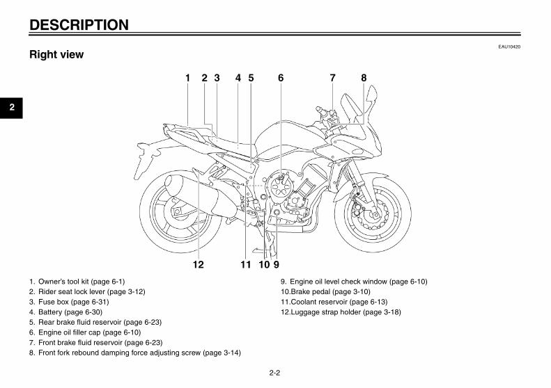
EAU10420
Right view
1. Owner’s tool kit (page 6-1)2. Rider seat lock lever (page 3-12)3. Fuse box (page 6-31)4. Battery (page 6-30)5. Rear brake fluid reservoir (page 6-23)6. Engine oil filler cap (page 6-10)7. Front brake fluid reservoir (page 6-23)8. Front fork rebound damping force adjusting screw (page 3-14)
9. Engine oil level check window (page 6-10)10.Brake pedal (page 3-10)11.Coolant reservoir (page 6-13)12.Luggage strap holder (page 3-18)
U3C311E0.book Page 2 Monday, September 11, 2006 1:18 PM
DESCRIPTION
2-3
2
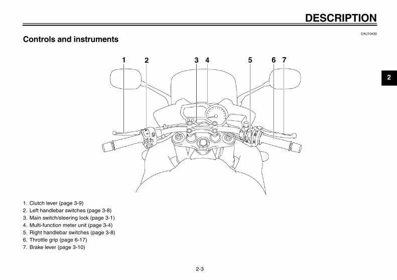
EAU10430
Controls and instruments
1. Clutch lever (page 3-9)2. Left handlebar switches (page 3-8)3. Main switch/steering lock (page 3-1)4. Multi-function meter unit (page 3-4)5. Right handlebar switches (page 3-8)6. Throttle grip (page 6-17)7. Brake lever (page 3-10)
U3C311E0.book Page 3 Monday, September 11, 2006 1:18 PM
INSTRUMENT AND CONTROL FUNCTIONS
3-1
3
EAU10460
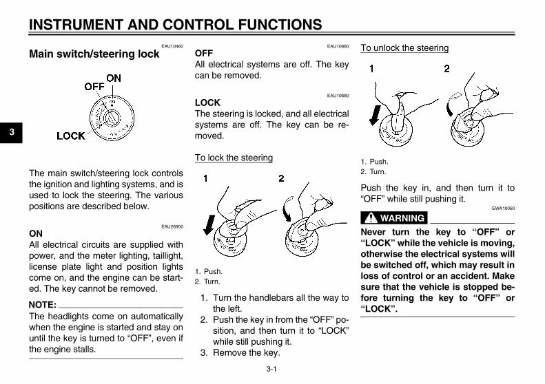
Main switch/steering lock
The main switch/steering lock controlsthe ignition and lighting systems, and isused to lock the steering. The variouspositions are described below.
EAU26900
ONAll electrical circuits are supplied withpower, and the meter lighting, taillight,license plate light and position lightscome on, and the engine can be start-ed. The key cannot be removed.
NOTE:The headlights come on automaticallywhen the engine is started and stay onuntil the key is turned to “OFF”, even ifthe engine stalls.
EAU10660
OFFAll electrical systems are off. The keycan be removed.
EAU10680
LOCKThe steering is locked, and all electricalsystems are off. The key can be re-moved.
To lock the steering
1. Turn the handlebars all the way tothe left.
2. Push the key in from the “OFF” po-sition, and then turn it to “LOCK”while still pushing it.
3. Remove the key.
To unlock the steering
Push the key in, and then turn it to“OFF” while still pushing it.
WARNINGEWA10060
Never turn the key to “OFF” or“LOCK” while the vehicle is moving,otherwise the electrical systems willbe switched off, which may result inloss of control or an accident. Makesure that the vehicle is stopped be-fore turning the key to “OFF” or“LOCK”.
1. Push.2. Turn.
1. Push.2. Turn.
U3C311E0.book Page 1 Monday, September 11, 2006 1:18 PM
INSTRUMENT AND CONTROL FUNCTIONS
3-2
3
EAU11003
Indicator and warning lights
EAU11030
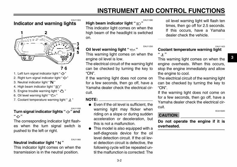
Turn signal indicator lights “ ” and “ ” The corresponding indicator light flash-es when the turn signal switch ispushed to the left or right.
EAU11060
Neutral indicator light “ ” This indicator light comes on when thetransmission is in the neutral position.
EAU11080
High beam indicator light “ ” This indicator light comes on when thehigh beam of the headlight is switchedon.
EAU11250
Oil level warning light “ ” This warning light comes on when theengine oil level is low.The electrical circuit of the warning lightcan be checked by turning the key to“ON”.If the warning light does not come onfor a few seconds, then go off, have aYamaha dealer check the electrical cir-cuit.
NOTE:� Even if the oil level is sufficient, the
warning light may flicker whenriding on a slope or during suddenacceleration or deceleration, butthis is not a malfunction.
� This model is also equipped with aself-diagnosis device for the oillevel detection circuit. If the oil lev-el detection circuit is defective, thefollowing cycle will be repeated un-til the malfunction is corrected: The
oil level warning light will flash tentimes, then go off for 2.5 seconds.If this occurs, have a Yamahadealer check the vehicle.
EAU11423
Coolant temperature warning light “ ” This warning light comes on when theengine overheats. When this occurs,stop the engine immediately and allowthe engine to cool.The electrical circuit of the warning lightcan be checked by turning the key to“ON”.If the warning light does not come onfor a few seconds, then go off, have aYamaha dealer check the electrical cir-cuit.
CAUTION:ECA10020
Do not operate the engine if it isoverheated.
1. Left turn signal indicator light “ ”2. Right turn signal indicator light “ ”3. Neutral indicator light “ ”4. High beam indicator light “ ”5. Engine trouble warning light “ ”6. Oil level warning light “ ”7. Coolant temperature warning light “ ”
U3C311E0.book Page 2 Monday, September 11, 2006 1:18 PM
INSTRUMENT AND CONTROL FUNCTIONS
3-3
3
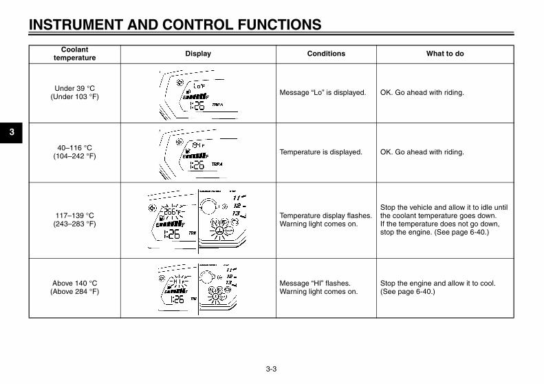
Coolant temperature Display Conditions What to do
Under 39 °C (Under 103 °F) Message “Lo” is displayed. OK. Go ahead with riding.
40–116 °C (104–242 °F) Temperature is displayed. OK. Go ahead with riding.
117–139 °C (243–283 °F)
Temperature display flashes.Warning light comes on.
Stop the vehicle and allow it to idle until the coolant temperature goes down.If the temperature does not go down, stop the engine. (See page 6-40.)
Above 140 °C (Above 284 °F)
Message “HI” flashes.Warning light comes on.
Stop the engine and allow it to cool. (See page 6-40.)
U3C311E0.book Page 3 Monday, September 11, 2006 1:18 PM
INSTRUMENT AND CONTROL FUNCTIONS
3-4
3
EAU11530
Engine trouble warning light “ ” This warning light comes on or flasheswhen an electrical circuit monitoring theengine is defective. When this occurs,have a Yamaha dealer check the self-diagnosis system. (See page 3-4 for anexplanation of the self-diagnosis de-vice.)The electrical circuit of the warning lightcan be checked by turning the key to“ON”. If the warning light does not comeon for a few seconds, then go off, havea Yamaha dealer check the electricalcircuit.
EAU40172
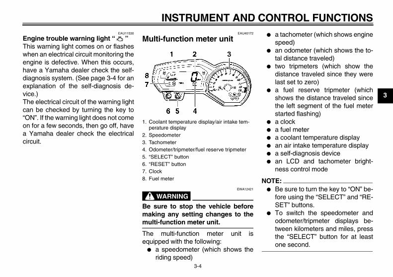
Multi-function meter unit
WARNINGEWA12421
Be sure to stop the vehicle beforemaking any setting changes to themulti-function meter unit.
The multi-function meter unit isequipped with the following:
� a speedometer (which shows theriding speed)
� a tachometer (which shows enginespeed)
� an odometer (which shows the to-tal distance traveled)
� two tripmeters (which show thedistance traveled since they werelast set to zero)
� a fuel reserve tripmeter (whichshows the distance traveled sincethe left segment of the fuel meterstarted flashing)
� a clock� a fuel meter� a coolant temperature display� an air intake temperature display� a self-diagnosis device� an LCD and tachometer bright-
ness control mode
NOTE:� Be sure to turn the key to “ON” be-
fore using the “SELECT” and “RE-SET” buttons.
� To switch the speedometer andodometer/tripmeter displays be-tween kilometers and miles, pressthe “SELECT” button for at leastone second.
1. Coolant temperature display/air intake tem-perature display
2. Speedometer3. Tachometer4. Odometer/tripmeter/fuel reserve tripmeter5. “SELECT” button6. “RESET” button7. Clock8. Fuel meter
U3C311E0.book Page 4 Monday, September 11, 2006 1:18 PM
INSTRUMENT AND CONTROL FUNCTIONS
3-5
3
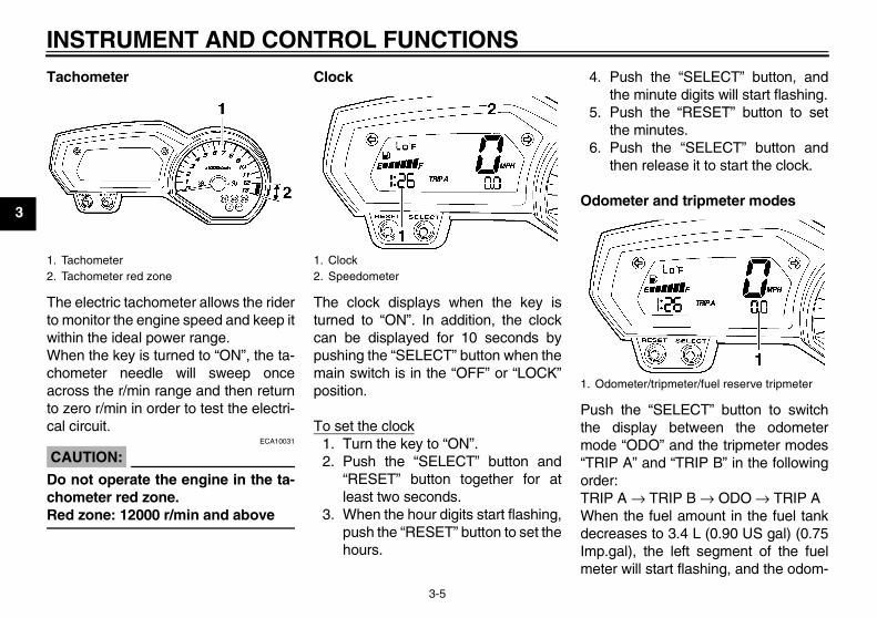
Tachometer
The electric tachometer allows the riderto monitor the engine speed and keep itwithin the ideal power range.When the key is turned to “ON”, the ta-chometer needle will sweep onceacross the r/min range and then returnto zero r/min in order to test the electri-cal circuit.
CAUTION:ECA10031
Do not operate the engine in the ta-chometer red zone.Red zone: 12000 r/min and above
Clock
The clock displays when the key isturned to “ON”. In addition, the clockcan be displayed for 10 seconds bypushing the “SELECT” button when themain switch is in the “OFF” or “LOCK”position.
To set the clock1. Turn the key to “ON”.2. Push the “SELECT” button and
“RESET” button together for atleast two seconds.
3. When the hour digits start flashing,push the “RESET” button to set thehours.
4. Push the “SELECT” button, andthe minute digits will start flashing.
5. Push the “RESET” button to setthe minutes.
6. Push the “SELECT” button andthen release it to start the clock.
Odometer and tripmeter modes
Push the “SELECT” button to switchthe display between the odometermode “ODO” and the tripmeter modes“TRIP A” and “TRIP B” in the followingorder:TRIP A → TRIP B → ODO → TRIP AWhen the fuel amount in the fuel tankdecreases to 3.4 L (0.90 US gal) (0.75Imp.gal), the left segment of the fuelmeter will start flashing, and the odom-
1. Tachometer2. Tachometer red zone
1. Clock2. Speedometer
1. Odometer/tripmeter/fuel reserve tripmeter
U3C311E0.book Page 5 Monday, September 11, 2006 1:18 PM
INSTRUMENT AND CONTROL FUNCTIONS
3-6
3
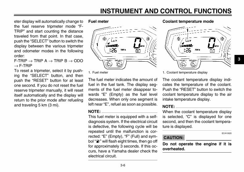
eter display will automatically change tothe fuel reserve tripmeter mode “F-TRIP” and start counting the distancetraveled from that point. In that case,push the “SELECT” button to switch thedisplay between the various tripmeterand odometer modes in the followingorder:F-TRIP → TRIP A → TRIP B → ODO→ F-TRIPTo reset a tripmeter, select it by push-ing the “SELECT” button, and thenpush the “RESET” button for at leastone second. If you do not reset the fuelreserve tripmeter manually, it will resetitself automatically and the display willreturn to the prior mode after refuelingand traveling 5 km (3 mi).
Fuel meter
The fuel meter indicates the amount offuel in the fuel tank. The display seg-ments of the fuel meter disappear to-wards “E” (Empty) as the fuel leveldecreases. When only one segment isleft near “E”, refuel as soon as possible.
NOTE:This fuel meter is equipped with a self-diagnosis system. If the electrical circuitis defective, the following cycle will berepeated until the malfunction is cor-rected: “E” (Empty), “F” (Full) and sym-bol “ ” will flash eight times, then go offfor approximately 3 seconds. If this oc-curs, have a Yamaha dealer check theelectrical circuit.
Coolant temperature mode
The coolant temperature display indi-cates the temperature of the coolant.Push the “RESET” button to switch thecoolant temperature display to the airintake temperature display.
NOTE:When the coolant temperature displayis selected, “C” is displayed for onesecond, and then the coolant tempera-ture is displayed.
CAUTION:ECA10020
Do not operate the engine if it isoverheated.
1. Fuel meter 1. Coolant temperature display
U3C311E0.book Page 6 Monday, September 11, 2006 1:18 PM
INSTRUMENT AND CONTROL FUNCTIONS
3-7
3
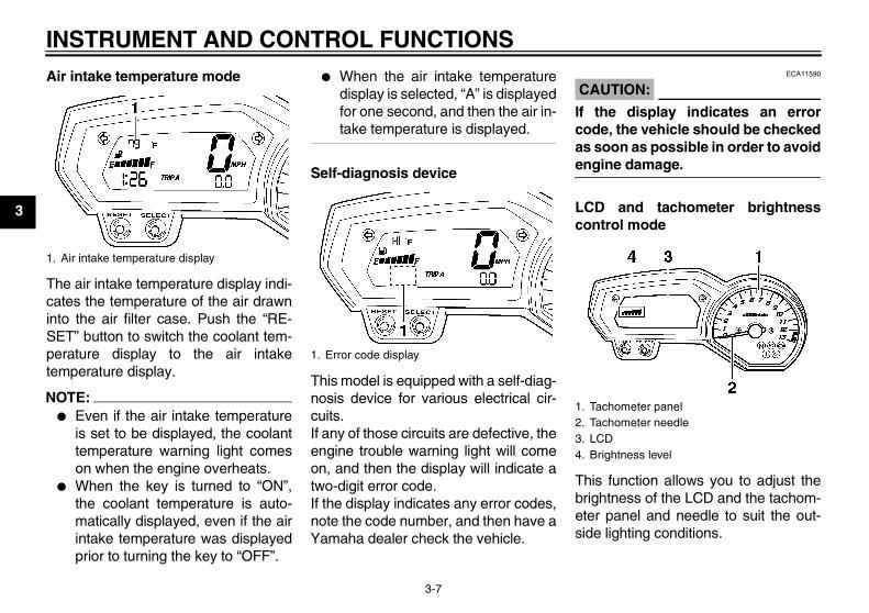
Air intake temperature mode
The air intake temperature display indi-cates the temperature of the air drawninto the air filter case. Push the “RE-SET” button to switch the coolant tem-perature display to the air intaketemperature display.
NOTE:� Even if the air intake temperature
is set to be displayed, the coolanttemperature warning light comeson when the engine overheats.
� When the key is turned to “ON”,the coolant temperature is auto-matically displayed, even if the airintake temperature was displayedprior to turning the key to “OFF”.
� When the air intake temperaturedisplay is selected, “A” is displayedfor one second, and then the air in-take temperature is displayed.
Self-diagnosis device
This model is equipped with a self-diag-nosis device for various electrical cir-cuits.If any of those circuits are defective, theengine trouble warning light will comeon, and then the display will indicate atwo-digit error code.If the display indicates any error codes,note the code number, and then have aYamaha dealer check the vehicle.
CAUTION:ECA11590
If the display indicates an errorcode, the vehicle should be checkedas soon as possible in order to avoidengine damage.
LCD and tachometer brightnesscontrol mode
This function allows you to adjust thebrightness of the LCD and the tachom-eter panel and needle to suit the out-side lighting conditions.
1. Air intake temperature display
1. Error code display
1. Tachometer panel2. Tachometer needle3. LCD4. Brightness level
U3C311E0.book Page 7 Monday, September 11, 2006 1:18 PM
INSTRUMENT AND CONTROL FUNCTIONS
3-8
3
To set the brightness1. Turn the key to “OFF”.2. Push and hold the “SELECT” but-
ton.3. Turn the key to “ON”, and then re-
lease the “SELECT” button afterfive seconds.
4. Push the “RESET” button to selectthe desired brightness level.
5. Push the “SELECT” button to con-firm the selected brightness level.The display will return to the odom-eter or tripmeter mode.
EAU12347
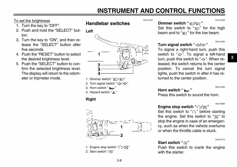
Handlebar switches
Left
Right
EAU12400
Dimmer switch “ / ” Set this switch to “ ” for the highbeam and to “ ” for the low beam.
EAU12460
Turn signal switch “ / ” To signal a right-hand turn, push thisswitch to “ ”. To signal a left-handturn, push this switch to “ ”. When re-leased, the switch returns to the centerposition. To cancel the turn signallights, push the switch in after it has re-turned to the center position.
EAU12500
Horn switch “ ” Press this switch to sound the horn.
EAU12660
Engine stop switch “ / ” Set this switch to “ ” before startingthe engine. Set this switch to “ ” tostop the engine in case of an emergen-cy, such as when the vehicle overturnsor when the throttle cable is stuck.
EAU12710
Start switch “ ” Push this switch to crank the enginewith the starter.
1. Dimmer switch “ / ”2. Turn signal switch “ / ”3. Horn switch “ ”4. Hazard switch “ ”
1. Engine stop switch “ / ”2. Start switch “ ”
U3C311E0.book Page 8 Monday, September 11, 2006 1:18 PM
INSTRUMENT AND CONTROL FUNCTIONS
3-9
3
CAUTION:ECA10050
See page 5-1 for starting instruc-tions prior to starting the engine.
EAU41700
The engine trouble warning light willcome on when the key is turned to “ON”and the start switch is pushed, but thisdoes not indicate a malfunction.
EAU12764
Hazard switch “ ” With the key in the “ON” position, turnthis switch to “ ” to turn on the hazardlights (simultaneous flashing of all turnsignal lights).The hazard lights are used in case ofan emergency or to warn other driverswhen your vehicle is stopped where itmight be a traffic hazard.
CAUTION:ECA10061
Do not use the hazard lights for anextended length of time with the en-gine not running, otherwise the bat-tery may discharge.
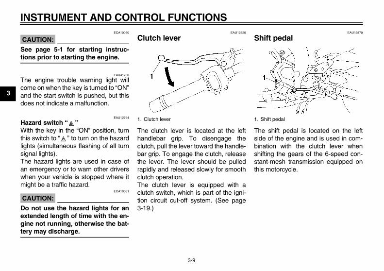
EAU12820
Clutch lever
The clutch lever is located at the lefthandlebar grip. To disengage theclutch, pull the lever toward the handle-bar grip. To engage the clutch, releasethe lever. The lever should be pulledrapidly and released slowly for smoothclutch operation.The clutch lever is equipped with aclutch switch, which is part of the igni-tion circuit cut-off system. (See page3-19.)
EAU12870
Shift pedal
The shift pedal is located on the leftside of the engine and is used in com-bination with the clutch lever whenshifting the gears of the 6-speed con-stant-mesh transmission equipped onthis motorcycle.
1. Clutch lever 1. Shift pedal
U3C311E0.book Page 9 Monday, September 11, 2006 1:18 PM
INSTRUMENT AND CONTROL FUNCTIONS
3-10
3
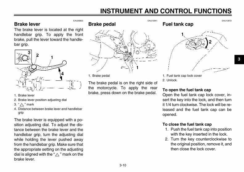
EAU26822
Brake lever The brake lever is located at the righthandlebar grip. To apply the frontbrake, pull the lever toward the handle-bar grip.
The brake lever is equipped with a po-sition adjusting dial. To adjust the dis-tance between the brake lever and thehandlebar grip, turn the adjusting dialwhile holding the lever pushed awayfrom the handlebar grip. Make sure thatthe appropriate setting on the adjustingdial is aligned with the “ ” mark on thebrake lever.
EAU12941
Brake pedal
The brake pedal is on the right side ofthe motorcycle. To apply the rearbrake, press down on the brake pedal.
EAU13072
Fuel tank cap
To open the fuel tank capOpen the fuel tank cap lock cover, in-sert the key into the lock, and then turnit 1/4 turn clockwise. The lock will be re-leased and the fuel tank cap can beopened.
To close the fuel tank cap1. Push the fuel tank cap into position
with the key inserted in the lock.2. Turn the key counterclockwise to
the original position, remove it, andthen close the lock cover.
1. Brake lever2. Brake lever position adjusting dial3. “ ” mark4. Distance between brake lever and handlebar
grip
1. Brake pedal 1. Fuel tank cap lock cover2. Unlock.
U3C311E0.book Page 10 Monday, September 11, 2006 1:18 PM
INSTRUMENT AND CONTROL FUNCTIONS
3-11
3
NOTE:The fuel tank cap cannot be closed un-less the key is in the lock. In addition,the key cannot be removed if the cap isnot properly closed and locked.
WARNINGEWA11090
Make sure that the fuel tank cap isproperly closed before riding.
EAU13220
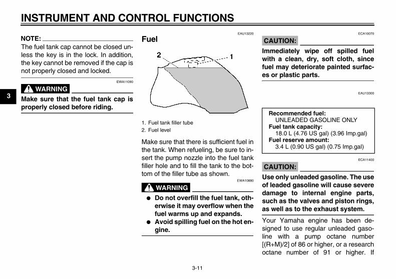
Fuel
Make sure that there is sufficient fuel inthe tank. When refueling, be sure to in-sert the pump nozzle into the fuel tankfiller hole and to fill the tank to the bot-tom of the filler tube as shown.
WARNINGEWA10880
� Do not overfill the fuel tank, oth-erwise it may overflow when thefuel warms up and expands.
� Avoid spilling fuel on the hot en-gine.
CAUTION:ECA10070
Immediately wipe off spilled fuelwith a clean, dry, soft cloth, sincefuel may deteriorate painted surfac-es or plastic parts.
EAU13300
CAUTION:ECA11400
Use only unleaded gasoline. The useof leaded gasoline will cause severedamage to internal engine parts,such as the valves and piston rings,as well as to the exhaust system.
Your Yamaha engine has been de-signed to use regular unleaded gaso-line with a pump octane number[(R+M)/2] of 86 or higher, or a researchoctane number of 91 or higher. If
1. Fuel tank filler tube2. Fuel level
Recommended fuel:UNLEADED GASOLINE ONLY
Fuel tank capacity:18.0 L (4.76 US gal) (3.96 Imp.gal)
Fuel reserve amount:3.4 L (0.90 US gal) (0.75 Imp.gal)
U3C311E0.book Page 11 Monday, September 11, 2006 1:18 PM
INSTRUMENT AND CONTROL FUNCTIONS
3-12
3
knocking (or pinging) occurs, use agasoline of a different brand or premi-um unleaded fuel. Use of unleaded fuelwill extend spark plug life and reducemaintenance costs.GasoholThere are two types of gasohol: gaso-hol containing ethanol and that contain-ing methanol. Gasohol containingethanol can be used if the ethanol con-tent does not exceed 10%. Gasoholcontaining methanol is not recom-mended by Yamaha because it cancause damage to the fuel system or ve-hicle performance problems.
EAU13441
Catalytic converter This vehicle is equipped with catalyticconverters in the exhaust system.
WARNINGEWA10860
The exhaust system is hot after op-eration. Make sure that the exhaustsystem has cooled down before do-ing any maintenance work.
CAUTION:ECA10700
The following precautions must beobserved to prevent a fire hazard orother damages.
� Use only unleaded gasoline.The use of leaded gasoline willcause unrepairable damage tothe catalytic converter.
� Never park the vehicle near pos-sible fire hazards such as grassor other materials that easilyburn.
� Do not allow the engine to idletoo long.
EAU39322
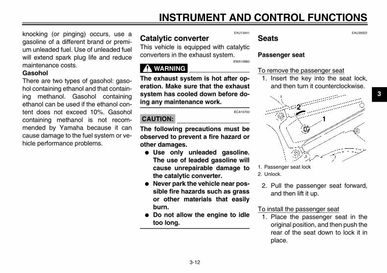
Seats
Passenger seat
To remove the passenger seat1. Insert the key into the seat lock,
and then turn it counterclockwise.
2. Pull the passenger seat forward,and then lift it up.
To install the passenger seat1. Place the passenger seat in the
original position, and then push therear of the seat down to lock it inplace.
1. Passenger seat lock2. Unlock.
U3C311E0.book Page 12 Monday, September 11, 2006 1:18 PM
INSTRUMENT AND CONTROL FUNCTIONS
3-13
3
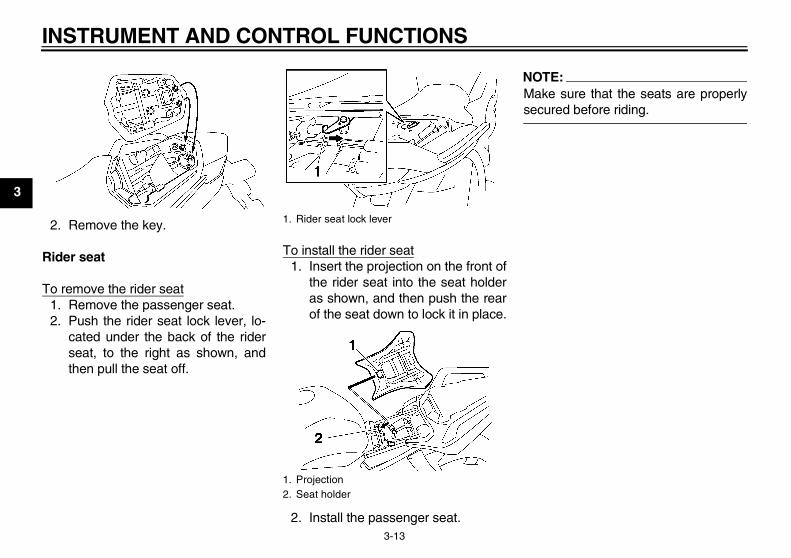
2. Remove the key.
Rider seat
To remove the rider seat1. Remove the passenger seat.2. Push the rider seat lock lever, lo-
cated under the back of the riderseat, to the right as shown, andthen pull the seat off.
To install the rider seat1. Insert the projection on the front of
the rider seat into the seat holderas shown, and then push the rearof the seat down to lock it in place.
2. Install the passenger seat.
NOTE:Make sure that the seats are properlysecured before riding.
1. Rider seat lock lever
1. Projection2. Seat holder
U3C311E0.book Page 13 Monday, September 11, 2006 1:18 PM
INSTRUMENT AND CONTROL FUNCTIONS
3-14
3
EAU14461
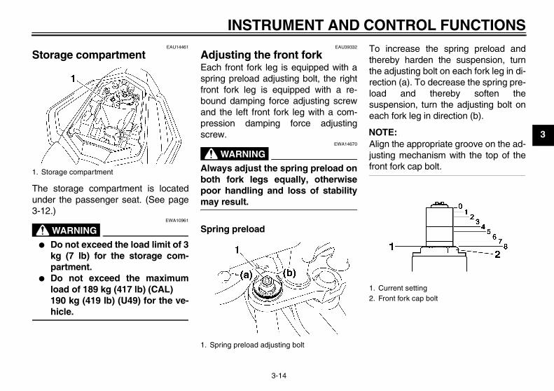
Storage compartment
The storage compartment is locatedunder the passenger seat. (See page3-12.)
WARNINGEWA10961
� Do not exceed the load limit of 3kg (7 lb) for the storage com-partment.
� Do not exceed the maximumload of 189 kg (417 lb) (CAL)190 kg (419 lb) (U49) for the ve-hicle.
EAU39332
Adjusting the front fork Each front fork leg is equipped with aspring preload adjusting bolt, the rightfront fork leg is equipped with a re-bound damping force adjusting screwand the left front fork leg with a com-pression damping force adjustingscrew.
WARNINGEWA14670
Always adjust the spring preload onboth fork legs equally, otherwisepoor handling and loss of stabilitymay result.
Spring preload
To increase the spring preload andthereby harden the suspension, turnthe adjusting bolt on each fork leg in di-rection (a). To decrease the spring pre-load and thereby soften thesuspension, turn the adjusting bolt oneach fork leg in direction (b).
NOTE:Align the appropriate groove on the ad-justing mechanism with the top of thefront fork cap bolt.
1. Storage compartment
1. Spring preload adjusting bolt
1. Current setting2. Front fork cap bolt
U3C311E0.book Page 14 Monday, September 11, 2006 1:18 PM
INSTRUMENT AND CONTROL FUNCTIONS
3-15
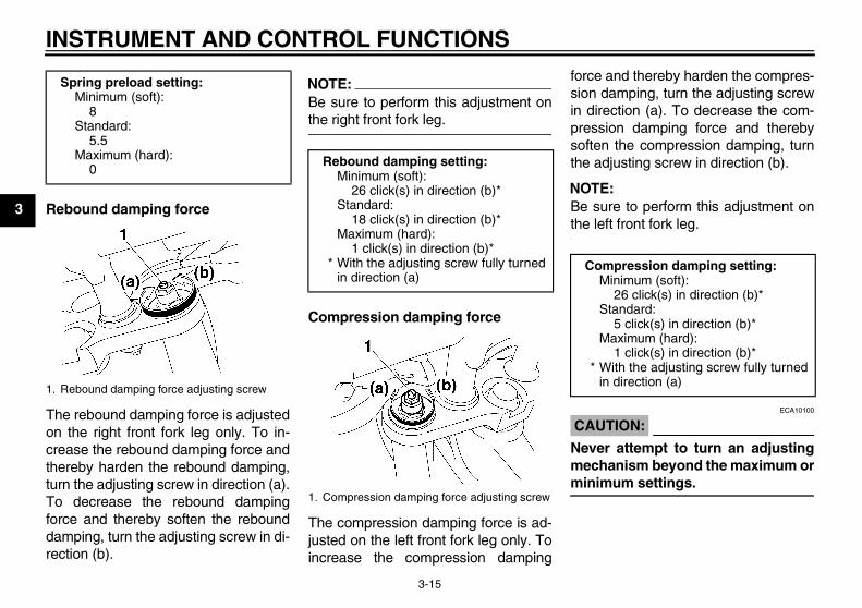
3 Rebound damping force
The rebound damping force is adjustedon the right front fork leg only. To in-crease the rebound damping force andthereby harden the rebound damping,turn the adjusting screw in direction (a).To decrease the rebound dampingforce and thereby soften the rebounddamping, turn the adjusting screw in di-rection (b).
NOTE:Be sure to perform this adjustment onthe right front fork leg.
Compression damping force
The compression damping force is ad-justed on the left front fork leg only. Toincrease the compression damping
force and thereby harden the compres-sion damping, turn the adjusting screwin direction (a). To decrease the com-pression damping force and therebysoften the compression damping, turnthe adjusting screw in direction (b).
NOTE:Be sure to perform this adjustment onthe left front fork leg.
CAUTION:ECA10100
Never attempt to turn an adjustingmechanism beyond the maximum orminimum settings.
Spring preload setting:Minimum (soft):
8Standard:
5.5Maximum (hard):
0
1. Rebound damping force adjusting screw
Rebound damping setting:Minimum (soft):
26 click(s) in direction (b)*Standard:
18 click(s) in direction (b)*Maximum (hard):
1 click(s) in direction (b)** With the adjusting screw fully turned
in direction (a)
1. Compression damping force adjusting screw
Compression damping setting:Minimum (soft):
26 click(s) in direction (b)*Standard:
5 click(s) in direction (b)*Maximum (hard):
1 click(s) in direction (b)** With the adjusting screw fully turned
in direction (a)
U3C311E0.book Page 15 Monday, September 11, 2006 1:18 PM
INSTRUMENT AND CONTROL FUNCTIONS
3-16
3
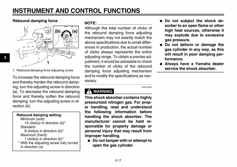
NOTE:Although the total number of clicks of adamping force adjusting mechanismmay not exactly match the above spec-ifications due to small differences inproduction, the actual number of clicksalways represents the entire adjustingrange. To obtain a precise adjustment,it would be advisable to check the num-ber of clicks of each damping force ad-justing mechanism and to modify thespecifications as necessary.
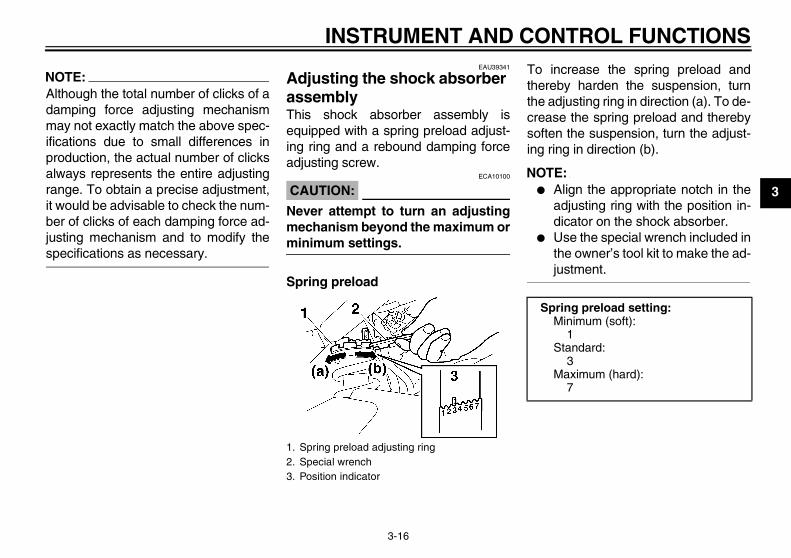
EAU39341
Adjusting the shock absorber assembly This shock absorber assembly isequipped with a spring preload adjust-ing ring and a rebound damping forceadjusting screw.
CAUTION:ECA10100
Never attempt to turn an adjustingmechanism beyond the maximum orminimum settings.
Spring preload
To increase the spring preload andthereby harden the suspension, turnthe adjusting ring in direction (a). To de-crease the spring preload and therebysoften the suspension, turn the adjust-ing ring in direction (b).
NOTE:� Align the appropriate notch in the
adjusting ring with the position in-dicator on the shock absorber.
� Use the special wrench included inthe owner’s tool kit to make the ad-justment.
1. Spring preload adjusting ring2. Special wrench3. Position indicator
Spring preload setting:Minimum (soft):
1Standard:
3Maximum (hard):
7
U3C311E0.book Page 16 Monday, September 11, 2006 1:18 PM
INSTRUMENT AND CONTROL FUNCTIONS
3-17
3
Rebound damping force
To increase the rebound damping forceand thereby harden the rebound damp-ing, turn the adjusting screw in direction(a). To decrease the rebound dampingforce and thereby soften the rebounddamping, turn the adjusting screw in di-rection (b).
NOTE:Although the total number of clicks ofthe rebound damping force adjustingmechanism may not exactly match theabove specifications due to small differ-ences in production, the actual numberof clicks always represents the entireadjusting range. To obtain a precise ad-justment, it would be advisable to checkthe number of clicks of the rebounddamping force adjusting mechanismand to modify the specifications as nec-essary.
WARNINGEWA10220
This shock absorber contains highlypressurized nitrogen gas. For prop-er handling, read and understandthe following information beforehandling the shock absorber. Themanufacturer cannot be held re-sponsible for property damage orpersonal injury that may result fromimproper handling.
� Do not tamper with or attempt toopen the gas cylinder.
� Do not subject the shock ab-sorber to an open flame or otherhigh heat sources, otherwise itmay explode due to excessivegas pressure.
� Do not deform or damage thegas cylinder in any way, as thiswill result in poor damping per-formance.
� Always have a Yamaha dealerservice the shock absorber.1. Rebound damping force adjusting screw
Rebound damping setting:Minimum (soft):
12 click(s) in direction (b)*Standard:
8 click(s) in direction (b)*Maximum (hard):
1 click(s) in direction (b)** With the adjusting screw fully turned
in direction (a)
U3C311E0.book Page 17 Monday, September 11, 2006 1:18 PM
INSTRUMENT AND CONTROL FUNCTIONS
3-18
3
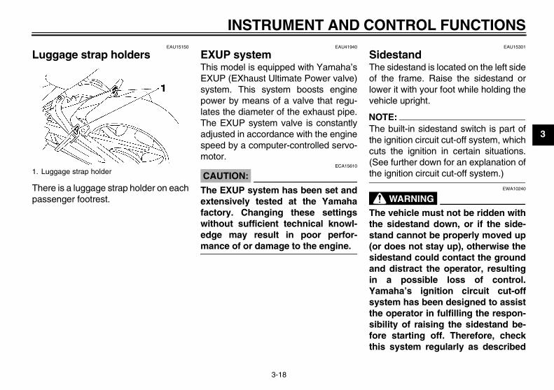
EAU15150
Luggage strap holders
There is a luggage strap holder on eachpassenger footrest.
EAU41940
EXUP system This model is equipped with Yamaha’sEXUP (EXhaust Ultimate Power valve)system. This system boosts enginepower by means of a valve that regu-lates the diameter of the exhaust pipe.The EXUP system valve is constantlyadjusted in accordance with the enginespeed by a computer-controlled servo-motor.
CAUTION:ECA15610
The EXUP system has been set andextensively tested at the Yamahafactory. Changing these settingswithout sufficient technical knowl-edge may result in poor perfor-mance of or damage to the engine.
EAU15301
Sidestand The sidestand is located on the left sideof the frame. Raise the sidestand orlower it with your foot while holding thevehicle upright.
NOTE:The built-in sidestand switch is part ofthe ignition circuit cut-off system, whichcuts the ignition in certain situations.(See further down for an explanation ofthe ignition circuit cut-off system.)
WARNINGEWA10240
The vehicle must not be ridden withthe sidestand down, or if the side-stand cannot be properly moved up(or does not stay up), otherwise thesidestand could contact the groundand distract the operator, resultingin a possible loss of control.Yamaha’s ignition circuit cut-offsystem has been designed to assistthe operator in fulfilling the respon-sibility of raising the sidestand be-fore starting off. Therefore, checkthis system regularly as described
1. Luggage strap holder
U3C311E0.book Page 18 Monday, September 11, 2006 1:18 PM
INSTRUMENT AND CONTROL FUNCTIONS
3-19
3
below and have a Yamaha dealer re-pair it if it does not function proper-ly.
EAU15321
Ignition circuit cut-off system The ignition circuit cut-off system (com-prising the sidestand switch, clutchswitch and neutral switch) has the fol-lowing functions.
� It prevents starting when the trans-mission is in gear and the side-stand is up, but the clutch lever isnot pulled.
� It prevents starting when the trans-mission is in gear and the clutch le-ver is pulled, but the sidestand isstill down.
� It cuts the running engine when thetransmission is in gear and the sid-estand is moved down.
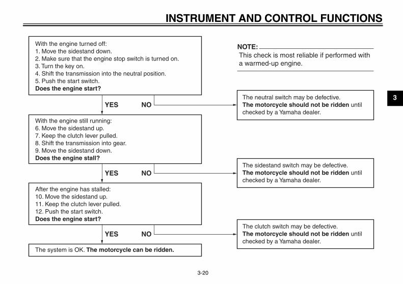
Periodically check the operation of theignition circuit cut-off system accordingto the following procedure.
WARNINGEWA10260
� The vehicle must be placed onthe centerstand during this in-spection.
� If a malfunction is noted, have aYamaha dealer check the sys-tem before riding.
U3C311E0.book Page 19 Monday, September 11, 2006 1:18 PM
INSTRUMENT AND CONTROL FUNCTIONS
3-20
3
With the engine turned off:1. Move the sidestand down.2. Make sure that the engine stop switch is turned on.3. Turn the key on. 4. Shift the transmission into the neutral position.5. Push the start switch.Does the engine start?
With the engine still running:6. Move the sidestand up.7. Keep the clutch lever pulled.8. Shift the transmission into gear.9. Move the sidestand down.Does the engine stall?
After the engine has stalled:10. Move the sidestand up.11. Keep the clutch lever pulled.12. Push the start switch.Does the engine start?
The system is OK. The motorcycle can be ridden.
This check is most reliable if performed witha warmed-up engine.
The neutral switch may be defective.The motorcycle should not be ridden untilchecked by a Yamaha dealer.
The sidestand switch may be defective.The motorcycle should not be ridden untilchecked by a Yamaha dealer.
The clutch switch may be defective.The motorcycle should not be ridden untilchecked by a Yamaha dealer.
YES NO
YES NO
YES NO
NOTE:
U3C311E0.book Page 20 Monday, September 11, 2006 1:18 PM
PRE-OPERATION CHECKS
4-1
4
EAU15592
The condition of a vehicle is the owner’s responsibility. Vital components can start to deteriorate quickly and unexpectedly,even if the vehicle remains unused (for example, as a result of exposure to the elements). Any damage, fluid leakage or lossof tire air pressure could have serious consequences. Therefore, it is very important, in addition to a thorough visual inspec-tion, to check the following points before each ride.
NOTE:Pre-operation checks should be made each time the vehicle is used. Such an inspection can be accomplished in a very shorttime; and the added safety it assures is more than worth the time involved.
WARNINGEWA11150
If any item in the Pre-operation check list is not working properly, have it inspected and repaired before operatingthe vehicle.
U3C311E0.book Page 1 Monday, September 11, 2006 1:18 PM
PRE-OPERATION CHECKS
4-2
4
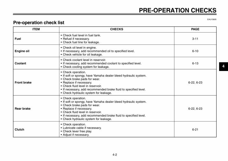
EAU15605
Pre-operation check list ITEM CHECKS PAGE
Fuel• Check fuel level in fuel tank.• Refuel if necessary.• Check fuel line for leakage.
3-11
Engine oil• Check oil level in engine.• If necessary, add recommended oil to specified level.• Check vehicle for oil leakage.
6-10
Coolant• Check coolant level in reservoir.• If necessary, add recommended coolant to specified level.• Check cooling system for leakage.
6-13
Front brake
• Check operation.• If soft or spongy, have Yamaha dealer bleed hydraulic system.• Check brake pads for wear.• Replace if necessary.• Check fluid level in reservoir.• If necessary, add recommended brake fluid to specified level.• Check hydraulic system for leakage.
6-22, 6-23
Rear brake
• Check operation.• If soft or spongy, have Yamaha dealer bleed hydraulic system.• Check brake pads for wear.• Replace if necessary.• Check fluid level in reservoir.• If necessary, add recommended brake fluid to specified level.• Check hydraulic system for leakage.
6-22, 6-23
Clutch
• Check operation.• Lubricate cable if necessary.• Check lever free play.• Adjust if necessary.
6-21
U3C311E0.book Page 2 Monday, September 11, 2006 1:18 PM
PRE-OPERATION CHECKS
4-3
4
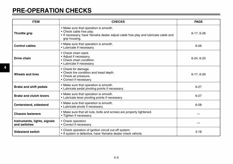
Throttle grip
• Make sure that operation is smooth.• Check cable free play.• If necessary, have Yamaha dealer adjust cable free play and lubricate cable and
grip housing.
6-17, 6-26
Control cables • Make sure that operation is smooth.• Lubricate if necessary. 6-26
Drive chain
• Check chain slack.• Adjust if necessary.• Check chain condition.• Lubricate if necessary.
6-24, 6-25
Wheels and tires
• Check for damage.• Check tire condition and tread depth.• Check air pressure.• Correct if necessary.
6-17, 6-20
Brake and shift pedals • Make sure that operation is smooth.• Lubricate pedal pivoting points if necessary. 6-27
Brake and clutch levers • Make sure that operation is smooth.• Lubricate lever pivoting points if necessary. 6-27
Centerstand, sidestand • Make sure that operation is smooth.• Lubricate pivots if necessary. 6-28
Chassis fasteners • Make sure that all nuts, bolts and screws are properly tightened.• Tighten if necessary. —
Instruments, lights, signals and switches
• Check operation.• Correct if necessary. —
Sidestand switch • Check operation of ignition circuit cut-off system.• If system is defective, have Yamaha dealer check vehicle. 3-18
ITEM CHECKS PAGE
U3C311E0.book Page 3 Monday, September 11, 2006 1:18 PM
OPERATION AND IMPORTANT RIDING POINTS
5-1
5
EAU15950
WARNINGEWA10270
� Become thoroughly familiarwith all operating controls andtheir functions before riding.Consult a Yamaha dealer re-garding any control or functionthat you do not thoroughly un-derstand.
� Never start the engine or oper-ate it in a closed area for anylength of time. Exhaust fumesare poisonous, and inhalingthem can cause loss of con-sciousness and death within ashort time. Always make surethat there is adequate ventila-tion.
� Before starting out, make surethat the sidestand is up. If thesidestand is not raised com-pletely, it could contact theground and distract the opera-tor, resulting in a possible lossof control.
EAU40190
Starting the engine In order for the ignition circuit cut-offsystem to enable starting, one of thefollowing conditions must be met.
� The transmission is in the neutralposition.
� The transmission is in gear withthe clutch lever pulled and the sid-estand up.
WARNINGEWA10290
� Before starting the engine,check the function of the igni-tion circuit cut-off system ac-cording to the proceduredescribed on page 3-19.
� Never ride with the sidestanddown.
1. Turn the key to “ON” and makesure that the engine stop switch isset to “ ”.
CAUTION:ECA15480
The following warning lights and in-dicator light should come on for afew seconds, then go off.
� Oil level warning light
� Coolant temperature warninglight
� Engine trouble warning lightIf a warning or indicator light doesnot go off, see page 3-2 for the corre-sponding warning and indicatorlight circuit check.
2. Shift the transmission into the neu-tral position.
NOTE:When the transmission is in the neutralposition, the neutral indicator lightshould be on, otherwise have aYamaha dealer check the electrical cir-cuit.
3. Start the engine by pushing thestart switch.
NOTE:If the engine fails to start, release thestart switch, wait a few seconds, andthen try again. Each starting attemptshould be as short as possible to pre-serve the battery. Do not crank the en-gine more than 10 seconds on any oneattempt.
U3C311E0.book Page 1 Monday, September 11, 2006 1:18 PM
OPERATION AND IMPORTANT RIDING POINTS
5-2
5
CAUTION:ECA15490
� If the oil level warning light flick-ers or remains on after starting,immediately stop the engine,and then check the engine oillevel and the vehicle for oil leak-age. If necessary, add engineoil, and then check the warninglight again.
� If the coolant temperature warn-ing light flickers or remains onafter starting, immediately stopthe engine, and then check thecoolant level and the vehicle forcoolant leakage. If necessary,add coolant, and then check thewarning light again.
� If the engine trouble warninglight flashes or remains on afterstarting, immediately stop theengine, and have a Yamahadealer check the cause.
CAUTION:ECA11130
For maximum engine life, alwayswarm the engine up before startingoff. Never accelerate hard when theengine is cold!
NOTE:The engine is warm when it quickly re-sponds to the throttle.
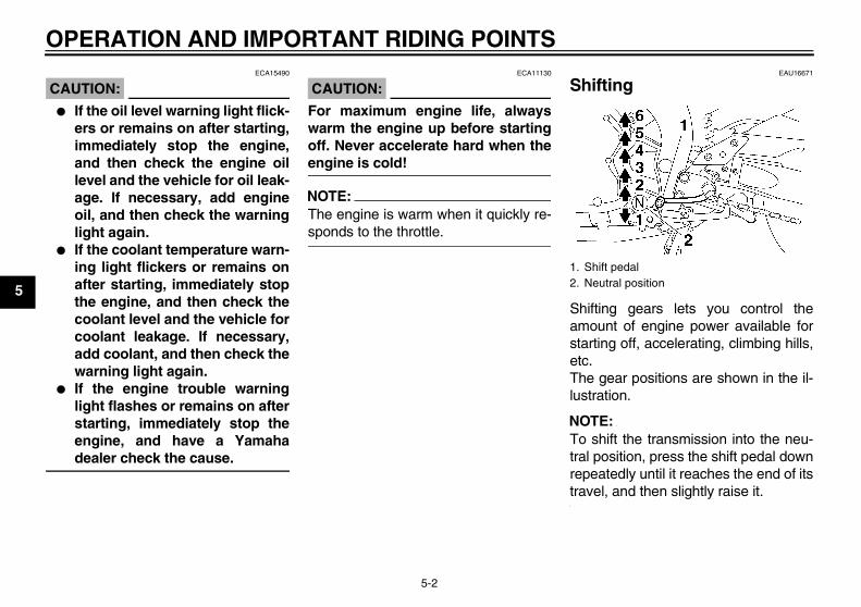
EAU16671
Shifting
Shifting gears lets you control theamount of engine power available forstarting off, accelerating, climbing hills,etc.The gear positions are shown in the il-lustration.
NOTE:To shift the transmission into the neu-tral position, press the shift pedal downrepeatedly until it reaches the end of itstravel, and then slightly raise it.
1. Shift pedal2. Neutral position
U3C311E0.book Page 2 Monday, September 11, 2006 1:18 PM
OPERATION AND IMPORTANT RIDING POINTS
5-3
5
CAUTION:ECA10260
� Even with the transmission inthe neutral position, do notcoast for long periods of timewith the engine off, and do nottow the motorcycle for long dis-tances. The transmission isproperly lubricated only whenthe engine is running. Inade-quate lubrication may damagethe transmission.
� Always use the clutch whilechanging gears to avoid damag-ing the engine, transmission,and drive train, which are notdesigned to withstand theshock of forced shifting.
EAU16680
To start out and accelerate1. Pull the clutch lever to disengage
the clutch.2. Shift the transmission into first
gear. The neutral indicator lightshould go out.
3. Open the throttle gradually, and atthe same time, release the clutchlever slowly.
4. At the recommended shift pointsshown in the following table, closethe throttle, and at the same time,quickly pull the clutch lever in.
5. Shift the transmission into secondgear. (Make sure not to shift thetransmission into the neutral posi-tion.)
6. Open the throttle part way andgradually release the clutch lever.
7. Follow the same procedure whenshifting to the next higher gear.
NOTE:Always shift gears at the recommendedshift points.
EAU16700
To decelerate1. Apply both the front and the rear
brakes to slow the motorcycle.2. Shift the transmission into first
gear when the motorcycle reaches25 km/h (15.5 mi/h). If the engine isabout to stall or runs very roughly,pull the clutch lever in and use thebrakes to stop the motorcycle.
3. Shift the transmission into the neu-tral position when the motorcycleis almost completely stopped. Theneutral indicator light should comeon.
EAU16740
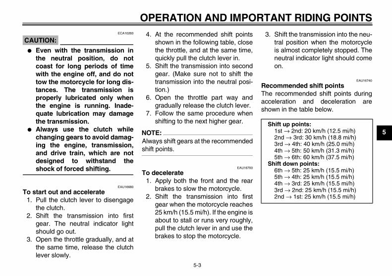
Recommended shift pointsThe recommended shift points duringacceleration and deceleration areshown in the table below.
Shift up points:1st → 2nd: 20 km/h (12.5 mi/h)2nd → 3rd: 30 km/h (18.8 mi/h)3rd → 4th: 40 km/h (25.0 mi/h)4th → 5th: 50 km/h (31.3 mi/h)5th → 6th: 60 km/h (37.5 mi/h)
Shift down points:6th → 5th: 25 km/h (15.5 mi/h)5th → 4th: 25 km/h (15.5 mi/h)4th → 3rd: 25 km/h (15.5 mi/h)3rd → 2nd: 25 km/h (15.5 mi/h)2nd → 1st: 25 km/h (15.5 mi/h)
U3C311E0.book Page 3 Monday, September 11, 2006 1:18 PM
OPERATION AND IMPORTANT RIDING POINTS
5-4
5
EAU16841
Engine break-in There is never a more important periodin the life of your engine than the periodbetween 0 and 1600 km (1000 mi). Forthis reason, you should read the follow-ing material carefully.Since the engine is brand new, do notput an excessive load on it for the first1600 km (1000 mi). The various parts inthe engine wear and polish themselvesto the correct operating clearances.During this period, prolonged full-throt-tle operation or any condition that mightresult in engine overheating must beavoided.
EAU17091
0–1000 km (0–600 mi)Avoid prolonged operation above 6000r/min.1000–1600 km (600–1000 mi)Avoid prolonged operation above 7200r/min.
CAUTION:ECA10301
After 1000 km (600 mi) of operation,the engine oil must be changed andthe oil filter cartridge or element re-placed.
1600 km (1000 mi) and beyondThe vehicle can now be operated nor-mally.
CAUTION:ECA10310
� Keep the engine speed out ofthe tachometer red zone.
� If any engine trouble should oc-cur during the engine break-inperiod, immediately have aYamaha dealer check the vehi-cle.
EAU17212
Parking When parking, stop the engine, andthen remove the key from the mainswitch.
WARNINGEWA10310
� Since the engine and exhaustsystem can become very hot,park in a place where pedestri-ans or children are not likely totouch them.
� Do not park on a slope or on softground, otherwise the vehiclemay overturn.
CAUTION:ECA10380
Never park in an area where thereare fire hazards such as grass orother flammable materials.
U3C311E0.book Page 4 Monday, September 11, 2006 1:18 PM

PERIODIC MAINTENANCE AND MINOR REPAIR
6-1
6
EAU17231
Safety is an obligation of the owner. Pe-riodic inspection, adjustment and lubri-cation will keep your vehicle in thesafest and most efficient condition pos-sible. The most important points ofmotorcycle inspection, adjustment, andlubrication are explained on the follow-ing pages.Maintenance, replacement, or repairof the emission control devices andsystems may be performed by anyrepair establishment or individualthat is certified (if applicable).
WARNINGEWA10320
If you are not familiar with mainte-nance work, have a Yamaha dealerdo it for you.
EAU17301
PERIODIC MAINTENANCE PROPER PERIODIC MAINTENANCEOF YOUR VEHICLE IS IMPORTANTIN ORDER TO ENJOY LONG, PLEA-SURABLE SERVICE. ESPECIALLYIMPORTANT ARE THE MAINTE-NANCE SERVICES RELATED TOEMISSIONS CONTROL. THESECONTROLS NOT ONLY FUNCTIONTO ENSURE CLEANER AIR, BUTARE ALSO VITAL TO PROPER EN-GINE OPERATION AND MAXIMUMPERFORMANCE. IN THE FOLLOW-ING PERIODIC MAINTENANCECHARTS, THE SERVICES RELATEDTO EMISSIONS CONTROL AREGROUPED SEPARATELY. THESESERVICES REQUIRE SPECIALIZEDDATA, KNOWLEDGE, AND EQUIP-MENT. YAMAHA DEALERS ARETRAINED AND EQUIPPED TO PER-FORM THESE PARTICULAR SER-VICES.
EAU17531
Owner’s tool kit
The owner’s tool kit is located under thepassenger seat. (See page 3-12.)The service information included in thismanual and the tools provided in theowner’s tool kit are intended to assistyou in the performance of preventivemaintenance and minor repairs. How-ever, additional tools such as a torquewrench may be necessary to performcertain maintenance work correctly.
NOTE:If you do not have the tools or experi-ence required for a particular job, havea Yamaha dealer perform it for you.
1. Owner’s tool kit
U3C311E0.book Page 1 Monday, September 11, 2006 1:18 PM
PERIODIC MAINTENANCE AND MINOR REPAIR
6-2
6
WARNINGEWA10340
Modifications not approved byYamaha may cause loss of perfor-mance, excessive emissions, andrender the vehicle unsafe for use.Consult a Yamaha dealer before at-tempting any changes.
U3C311E0.book Page 2 Monday, September 11, 2006 1:18 PM
PERIODIC MAINTENANCE AND MINOR REPAIR
6-3
6
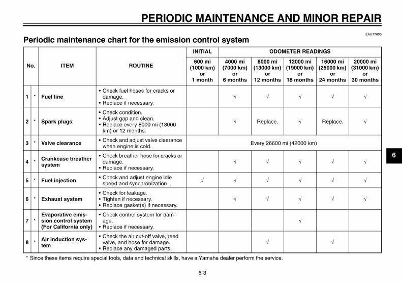
EAU17600
Periodic maintenance chart for the emission control system
* Since these items require special tools, data and technical skills, have a Yamaha dealer perform the service.
No. ITEM ROUTINE
INITIAL ODOMETER READINGS
600 mi (1000 km)
or 1 month
4000 mi (7000 km)
or 6 months
8000 mi (13000 km)
or 12 months
12000 mi (19000 km)
or 18 months
16000 mi (25000 km)
or 24 months
20000 mi (31000 km)
or 30 months
1 * Fuel line• Check fuel hoses for cracks or
damage.• Replace if necessary.
√ √ √ √ √
2 * Spark plugs
• Check condition.• Adjust gap and clean.• Replace every 8000 mi (13000
km) or 12 months.
√ Replace. √ Replace. √
3 * Valve clearance • Check and adjust valve clearance when engine is cold. Every 26600 mi (42000 km)
4 * Crankcase breather system
• Check breather hose for cracks or damage.
• Replace if necessary.√ √ √ √ √
5 * Fuel injection • Check and adjust engine idle speed and synchronization. √ √ √ √ √ √
6 * Exhaust system• Check for leakage.• Tighten if necessary.• Replace gasket(s) if necessary.
√ √ √ √ √
7 *Evaporative emis-sion control system (For California only)
• Check control system for dam-age.
• Replace if necessary.√
8 * Air induction sys-tem
• Check the air cut-off valve, reed valve, and hose for damage.
• Replace any damaged parts.√ √
U3C311E0.book Page 3 Monday, September 11, 2006 1:18 PM
PERIODIC MAINTENANCE AND MINOR REPAIR
6-4
6
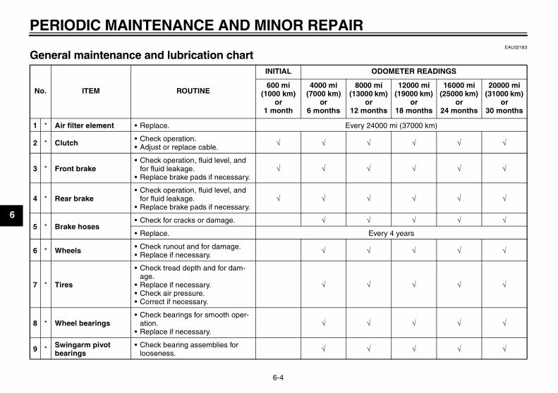
EAU32183
General maintenance and lubrication chart
No. ITEM ROUTINE
INITIAL ODOMETER READINGS
600 mi (1000 km)
or 1 month
4000 mi (7000 km)
or 6 months
8000 mi (13000 km)
or 12 months
12000 mi (19000 km)
or 18 months
16000 mi (25000 km)
or 24 months
20000 mi (31000 km)
or 30 months
1 * Air filter element • Replace. Every 24000 mi (37000 km)
2 * Clutch • Check operation.• Adjust or replace cable. √ √ √ √ √ √
3 * Front brake• Check operation, fluid level, and
for fluid leakage.• Replace brake pads if necessary.
√ √ √ √ √ √
4 * Rear brake• Check operation, fluid level, and
for fluid leakage.• Replace brake pads if necessary.
√ √ √ √ √ √
5 * Brake hoses• Check for cracks or damage. √ √ √ √ √
• Replace. Every 4 years
6 * Wheels • Check runout and for damage.• Replace if necessary. √ √ √ √ √
7 * Tires
• Check tread depth and for dam-age.
• Replace if necessary.• Check air pressure.• Correct if necessary.
√ √ √ √ √
8 * Wheel bearings• Check bearings for smooth oper-
ation.• Replace if necessary.
√ √ √ √ √
9 * Swingarm pivot bearings
• Check bearing assemblies for looseness. √ √ √ √ √
U3C311E0.book Page 4 Monday, September 11, 2006 1:18 PM
PERIODIC MAINTENANCE AND MINOR REPAIR
6-5
6
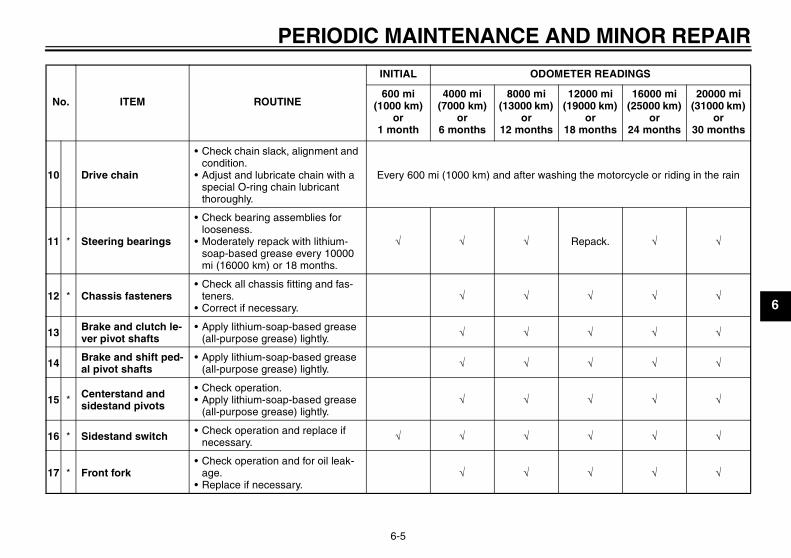
10 Drive chain
• Check chain slack, alignment and condition.
• Adjust and lubricate chain with a special O-ring chain lubricant thoroughly.
Every 600 mi (1000 km) and after washing the motorcycle or riding in the rain
11 * Steering bearings
• Check bearing assemblies for looseness.
• Moderately repack with lithium-soap-based grease every 10000 mi (16000 km) or 18 months.
√ √ √ Repack. √ √
12 * Chassis fasteners• Check all chassis fitting and fas-
teners.• Correct if necessary.
√ √ √ √ √
13 Brake and clutch le-ver pivot shafts
• Apply lithium-soap-based grease (all-purpose grease) lightly. √ √ √ √ √
14 Brake and shift ped-al pivot shafts
• Apply lithium-soap-based grease (all-purpose grease) lightly. √ √ √ √ √
15 * Centerstand and sidestand pivots
• Check operation.• Apply lithium-soap-based grease
(all-purpose grease) lightly.√ √ √ √ √
16 * Sidestand switch • Check operation and replace if necessary. √ √ √ √ √ √
17 * Front fork• Check operation and for oil leak-
age.• Replace if necessary.
√ √ √ √ √
No. ITEM ROUTINE
INITIAL ODOMETER READINGS
600 mi (1000 km)
or 1 month
4000 mi (7000 km)
or 6 months
8000 mi (13000 km)
or 12 months
12000 mi (19000 km)
or 18 months
16000 mi (25000 km)
or 24 months
20000 mi (31000 km)
or 30 months
U3C311E0.book Page 5 Monday, September 11, 2006 1:18 PM
PERIODIC MAINTENANCE AND MINOR REPAIR
6-6
6
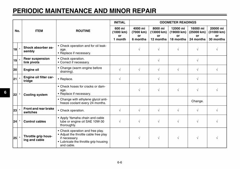
18 * Shock absorber as-sembly
• Check operation and for oil leak-age.
• Replace if necessary.√ √ √ √ √
19 * Rear suspension link pivots
• Check operation.• Correct if necessary. √ √
20 Engine oil • Change (warm engine before draining). √ √ √ √ √ √
21 * Engine oil filter car-tridge • Replace. √ √ √
22 * Cooling system
• Check hoses for cracks or dam-age.
• Replace if necessary.√ √ √ √ √
• Change with ethylene glycol anti-freeze coolant every 24 months. Change.
23 * Front and rear brake switches • Check operation. √ √ √ √ √ √
24 * Control cables• Apply Yamaha chain and cable
lube or engine oil SAE 10W-30 thoroughly.
√ √ √ √ √ √
25 * Throttle grip hous-ing and cable
• Check operation and free play.• Adjust the throttle cable free play
if necessary.• Lubricate the throttle grip housing
and cable.
√ √ √ √ √
No. ITEM ROUTINE
INITIAL ODOMETER READINGS
600 mi (1000 km)
or 1 month
4000 mi (7000 km)
or 6 months
8000 mi (13000 km)
or 12 months
12000 mi (19000 km)
or 18 months
16000 mi (25000 km)
or 24 months
20000 mi (31000 km)
or 30 months
U3C311E0.book Page 6 Monday, September 11, 2006 1:18 PM
PERIODIC MAINTENANCE AND MINOR REPAIR
6-7
6
* Since these items require special tools, data and technical skills, have a Yamaha dealer perform the service.
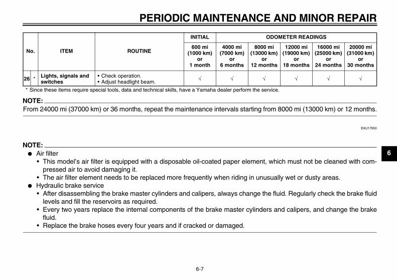
NOTE:From 24000 mi (37000 km) or 36 months, repeat the maintenance intervals starting from 8000 mi (13000 km) or 12 months.
EAU17650
NOTE:� Air filter
• This model’s air filter is equipped with a disposable oil-coated paper element, which must not be cleaned with com-pressed air to avoid damaging it.
• The air filter element needs to be replaced more frequently when riding in unusually wet or dusty areas.� Hydraulic brake service
• After disassembling the brake master cylinders and calipers, always change the fluid. Regularly check the brake fluidlevels and fill the reservoirs as required.
• Every two years replace the internal components of the brake master cylinders and calipers, and change the brakefluid.
• Replace the brake hoses every four years and if cracked or damaged.
26 * Lights, signals and switches
• Check operation.• Adjust headlight beam. √ √ √ √ √ √
No. ITEM ROUTINE
INITIAL ODOMETER READINGS
600 mi (1000 km)
or 1 month
4000 mi (7000 km)
or 6 months
8000 mi (13000 km)
or 12 months
12000 mi (19000 km)
or 18 months
16000 mi (25000 km)
or 24 months
20000 mi (31000 km)
or 30 months
U3C311E0.book Page 7 Monday, September 11, 2006 1:18 PM
PERIODIC MAINTENANCE AND MINOR REPAIR
6-8
6
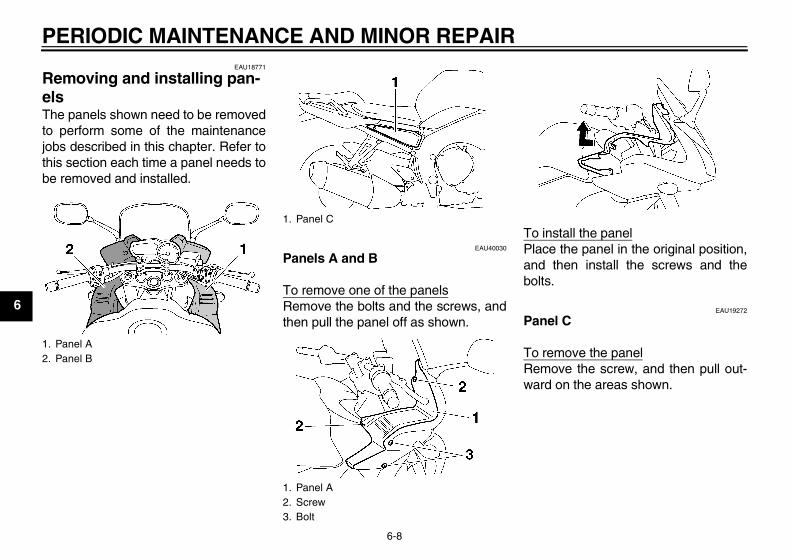
EAU18771
Removing and installing pan-els The panels shown need to be removedto perform some of the maintenancejobs described in this chapter. Refer tothis section each time a panel needs tobe removed and installed.
EAU40030
Panels A and B
To remove one of the panelsRemove the bolts and the screws, andthen pull the panel off as shown.
To install the panelPlace the panel in the original position,and then install the screws and thebolts.
EAU19272
Panel C
To remove the panelRemove the screw, and then pull out-ward on the areas shown.
1. Panel A2. Panel B
1. Panel C
1. Panel A2. Screw3. Bolt
U3C311E0.book Page 8 Monday, September 11, 2006 1:18 PM
PERIODIC MAINTENANCE AND MINOR REPAIR
6-9
6
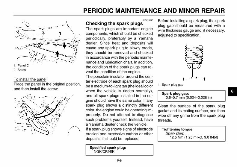
To install the panelPlace the panel in the original position,and then install the screw.
EAU19652
Checking the spark plugs The spark plugs are important enginecomponents, which should be checkedperiodically, preferably by a Yamahadealer. Since heat and deposits willcause any spark plug to slowly erode,they should be removed and checkedin accordance with the periodic mainte-nance and lubrication chart. In addition,the condition of the spark plugs can re-veal the condition of the engine.The porcelain insulator around the cen-ter electrode of each spark plug shouldbe a medium-to-light tan (the ideal colorwhen the vehicle is ridden normally),and all spark plugs installed in the en-gine should have the same color. If anyspark plug shows a distinctly differentcolor, the engine could be operating im-properly. Do not attempt to diagnosesuch problems yourself. Instead, havea Yamaha dealer check the vehicle.If a spark plug shows signs of electrodeerosion and excessive carbon or otherdeposits, it should be replaced.
Before installing a spark plug, the sparkplug gap should be measured with awire thickness gauge and, if necessary,adjusted to specification.
Clean the surface of the spark pluggasket and its mating surface, and thenwipe off any grime from the spark plugthreads.
1. Panel C2. Screw
Specified spark plug:NGK/CR9EK
1. Spark plug gap
Spark plug gap:0.6–0.7 mm (0.024–0.028 in)
Tightening torque:Spark plug:
12.5 Nm (1.25 m·kgf, 9.0 ft·lbf)
U3C311E0.book Page 9 Monday, September 11, 2006 1:18 PM
PERIODIC MAINTENANCE AND MINOR REPAIR
6-10
6
NOTE:If a torque wrench is not available wheninstalling a spark plug, a good estimateof the correct torque is 1/4–1/2 turnpast finger tight. However, the sparkplug should be tightened to the speci-fied torque as soon as possible.
CAUTION:ECA10840
Do not use any tools to remove or in-stall the spark plug cap, otherwisethe ignition coil coupler may getdamaged. The spark plug cap maybe difficult to remove because therubber seal on the end of the cap fitstightly. To remove the spark plugcap, simply twist it back and forthwhile pulling it out; to install it, twistit back and forth while pushing it in.
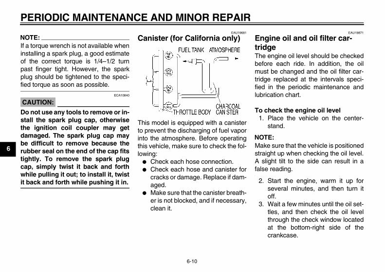
EAU19681
Canister (for California only)
This model is equipped with a canisterto prevent the discharging of fuel vaporinto the atmosphere. Before operatingthis vehicle, make sure to check the fol-lowing:
� Check each hose connection.� Check each hose and canister for
cracks or damage. Replace if dam-aged.
� Make sure that the canister breath-er is not blocked, and if necessary,clean it.
EAU19871
Engine oil and oil filter car-tridge The engine oil level should be checkedbefore each ride. In addition, the oilmust be changed and the oil filter car-tridge replaced at the intervals speci-fied in the periodic maintenance andlubrication chart.
To check the engine oil level1. Place the vehicle on the center-
stand.
NOTE:Make sure that the vehicle is positionedstraight up when checking the oil level.A slight tilt to the side can result in afalse reading.
2. Start the engine, warm it up forseveral minutes, and then turn itoff.
3. Wait a few minutes until the oil set-tles, and then check the oil levelthrough the check window locatedat the bottom-right side of thecrankcase.
U3C311E0.book Page 10 Monday, September 11, 2006 1:18 PM
PERIODIC MAINTENANCE AND MINOR REPAIR
6-11
6
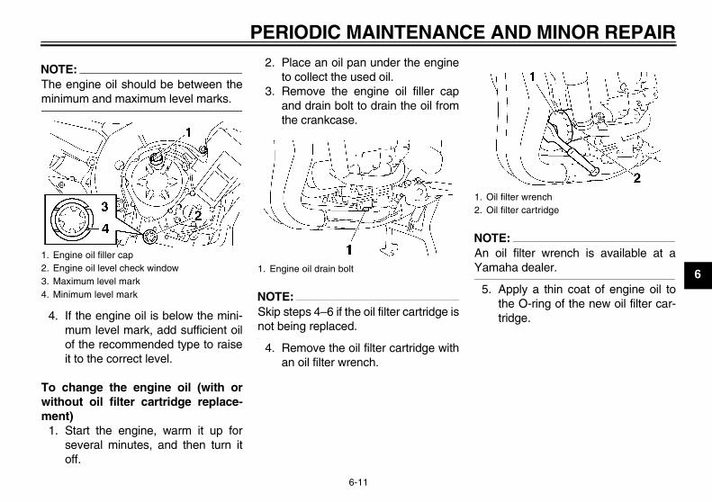
NOTE:The engine oil should be between theminimum and maximum level marks.
4. If the engine oil is below the mini-mum level mark, add sufficient oilof the recommended type to raiseit to the correct level.
To change the engine oil (with orwithout oil filter cartridge replace-ment)
1. Start the engine, warm it up forseveral minutes, and then turn itoff.
2. Place an oil pan under the engineto collect the used oil.
3. Remove the engine oil filler capand drain bolt to drain the oil fromthe crankcase.
NOTE:Skip steps 4–6 if the oil filter cartridge isnot being replaced.
4. Remove the oil filter cartridge withan oil filter wrench.
NOTE:An oil filter wrench is available at aYamaha dealer.
5. Apply a thin coat of engine oil tothe O-ring of the new oil filter car-tridge.
1. Engine oil filler cap2. Engine oil level check window3. Maximum level mark4. Minimum level mark
1. Engine oil drain bolt
1. Oil filter wrench2. Oil filter cartridge
U3C311E0.book Page 11 Monday, September 11, 2006 1:18 PM
PERIODIC MAINTENANCE AND MINOR REPAIR
6-12
6
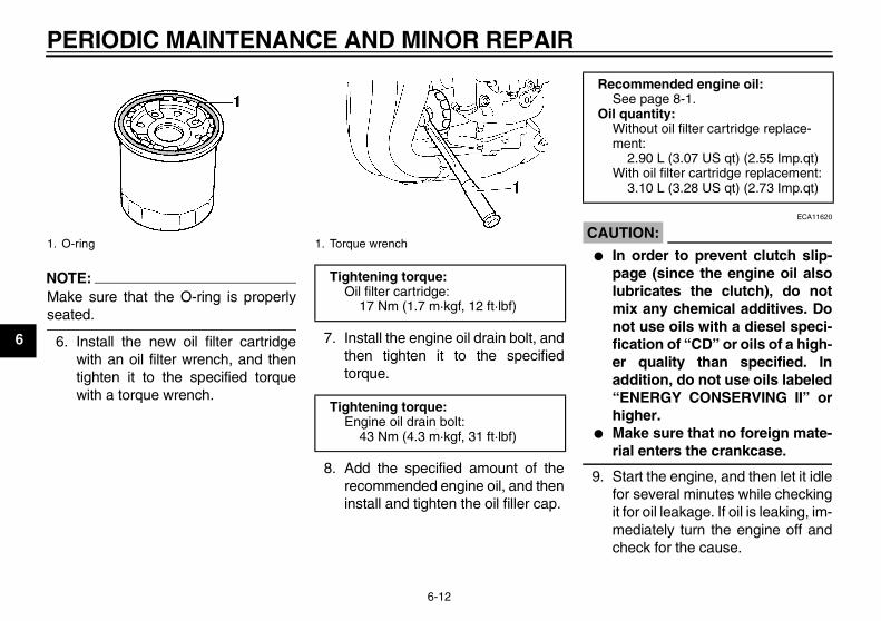
NOTE:Make sure that the O-ring is properlyseated.
6. Install the new oil filter cartridgewith an oil filter wrench, and thentighten it to the specified torquewith a torque wrench.
7. Install the engine oil drain bolt, andthen tighten it to the specifiedtorque.
8. Add the specified amount of therecommended engine oil, and theninstall and tighten the oil filler cap.
CAUTION:ECA11620
� In order to prevent clutch slip-page (since the engine oil alsolubricates the clutch), do notmix any chemical additives. Donot use oils with a diesel speci-fication of “CD” or oils of a high-er quality than specified. Inaddition, do not use oils labeled“ENERGY CONSERVING II” orhigher.
� Make sure that no foreign mate-rial enters the crankcase.
9. Start the engine, and then let it idlefor several minutes while checkingit for oil leakage. If oil is leaking, im-mediately turn the engine off andcheck for the cause.
1. O-ring 1. Torque wrench
Tightening torque:Oil filter cartridge:
17 Nm (1.7 m·kgf, 12 ft·lbf)
Tightening torque:Engine oil drain bolt:
43 Nm (4.3 m·kgf, 31 ft·lbf)
Recommended engine oil:See page 8-1.
Oil quantity:Without oil filter cartridge replace-ment:
2.90 L (3.07 US qt) (2.55 Imp.qt)With oil filter cartridge replacement:
3.10 L (3.28 US qt) (2.73 Imp.qt)
U3C311E0.book Page 12 Monday, September 11, 2006 1:18 PM
PERIODIC MAINTENANCE AND MINOR REPAIR
6-13
6
NOTE:After the engine is started, the engineoil level warning light should go off if theoil level is sufficient.
CAUTION:ECA10400
If the oil level warning light flickersor remains on, immediately turn theengine off and have a Yamaha dealercheck the vehicle.
10. Turn the engine off, and thencheck the oil level and correct it ifnecessary.
EAU20070
Coolant The coolant level should be checkedbefore each ride. In addition, the cool-ant must be changed at the intervalsspecified in the periodic maintenanceand lubrication chart.
EAU40041
To check the coolant level1. Place the vehicle on the center-
stand.
NOTE:� The coolant level must be checked
on a cold engine since the levelvaries with engine temperature.
� Make sure that the vehicle is posi-tioned straight up when checkingthe coolant level. A slight tilt to theside can result in an incorrectreading.
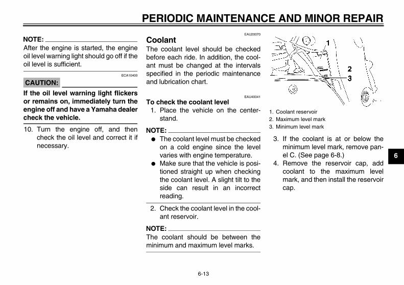
2. Check the coolant level in the cool-ant reservoir.
NOTE:The coolant should be between theminimum and maximum level marks.
3. If the coolant is at or below theminimum level mark, remove pan-el C. (See page 6-8.)
4. Remove the reservoir cap, addcoolant to the maximum levelmark, and then install the reservoircap.
1. Coolant reservoir2. Maximum level mark3. Minimum level mark
U3C311E0.book Page 13 Monday, September 11, 2006 1:18 PM
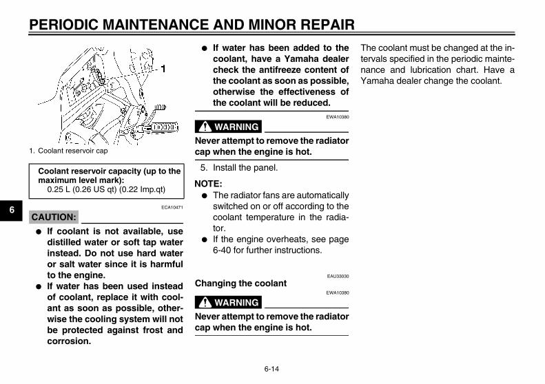
PERIODIC MAINTENANCE AND MINOR REPAIR
6-14
6CAUTION:
ECA10471
� If coolant is not available, usedistilled water or soft tap waterinstead. Do not use hard wateror salt water since it is harmfulto the engine.
� If water has been used insteadof coolant, replace it with cool-ant as soon as possible, other-wise the cooling system will notbe protected against frost andcorrosion.
� If water has been added to thecoolant, have a Yamaha dealercheck the antifreeze content ofthe coolant as soon as possible,otherwise the effectiveness ofthe coolant will be reduced.
WARNINGEWA10380
Never attempt to remove the radiatorcap when the engine is hot.
5. Install the panel.
NOTE:� The radiator fans are automatically
switched on or off according to thecoolant temperature in the radia-tor.
� If the engine overheats, see page6-40 for further instructions.
EAU33030
Changing the coolant
WARNINGEWA10380
Never attempt to remove the radiatorcap when the engine is hot.
The coolant must be changed at the in-tervals specified in the periodic mainte-nance and lubrication chart. Have aYamaha dealer change the coolant.
1. Coolant reservoir cap
Coolant reservoir capacity (up to the maximum level mark):
0.25 L (0.26 US qt) (0.22 Imp.qt)
U3C311E0.book Page 14 Monday, September 11, 2006 1:18 PM
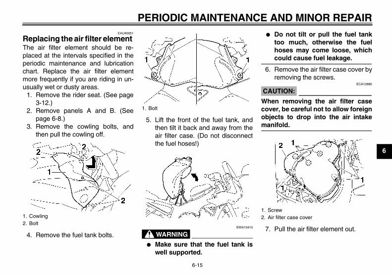
PERIODIC MAINTENANCE AND MINOR REPAIR
6-15
6
EAU40051
Replacing the air filter element The air filter element should be re-placed at the intervals specified in theperiodic maintenance and lubricationchart. Replace the air filter elementmore frequently if you are riding in un-usually wet or dusty areas.
1. Remove the rider seat. (See page3-12.)
2. Remove panels A and B. (Seepage 6-8.)
3. Remove the cowling bolts, andthen pull the cowling off.
4. Remove the fuel tank bolts.
5. Lift the front of the fuel tank, andthen tilt it back and away from theair filter case. (Do not disconnectthe fuel hoses!)
WARNINGEWA10410
� Make sure that the fuel tank iswell supported.
� Do not tilt or pull the fuel tanktoo much, otherwise the fuelhoses may come loose, whichcould cause fuel leakage.
6. Remove the air filter case cover byremoving the screws.
CAUTION:ECA12880
When removing the air filter casecover, be careful not to allow foreignobjects to drop into the air intakemanifold.
7. Pull the air filter element out.
1. Cowling2. Bolt
1. Bolt
1. Screw2. Air filter case cover
U3C311E0.book Page 15 Monday, September 11, 2006 1:18 PM
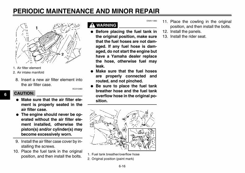
PERIODIC MAINTENANCE AND MINOR REPAIR
6-16
6
8. Insert a new air filter element intothe air filter case.
CAUTION:ECA10480
� Make sure that the air filter ele-ment is properly seated in theair filter case.
� The engine should never be op-erated without the air filter ele-ment installed, otherwise thepiston(s) and/or cylinder(s) maybecome excessively worn.
9. Install the air filter case cover by in-stalling the screws.
10. Place the fuel tank in the originalposition, and then install the bolts.
WARNINGEWA11360
� Before placing the fuel tank inthe original position, make surethat the fuel hoses are not dam-aged. If any fuel hose is dam-aged, do not start the engine buthave a Yamaha dealer replacethe hose, otherwise fuel mayleak.
� Make sure that the fuel hosesare properly connected androuted, and not pinched.
� Be sure to place the fuel tankbreather hose and the fuel tankoverflow hose in the original po-sition.
11. Place the cowling in the originalposition, and then install the bolts.
12. Install the panels.13. Install the rider seat.
1. Air filter element2. Air intake manifold
1. Fuel tank breather/overflow hose2. Original position (paint mark)
U3C311E0.book Page 16 Monday, September 11, 2006 1:18 PM
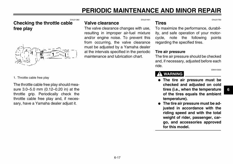
PERIODIC MAINTENANCE AND MINOR REPAIR
6-17
6
EAU21382
Checking the throttle cable free play
The throttle cable free play should mea-sure 3.0–5.0 mm (0.12–0.20 in) at thethrottle grip. Periodically check thethrottle cable free play and, if neces-sary, have a Yamaha dealer adjust it.
EAU21401
Valve clearance The valve clearance changes with use,resulting in improper air-fuel mixtureand/or engine noise. To prevent thisfrom occurring, the valve clearancemust be adjusted by a Yamaha dealerat the intervals specified in the periodicmaintenance and lubrication chart.
EAU21750
Tires To maximize the performance, durabil-ity, and safe operation of your motor-cycle, note the following pointsregarding the specified tires.
Tire air pressureThe tire air pressure should be checkedand, if necessary, adjusted before eachride.
WARNINGEWA10500
� The tire air pressure must bechecked and adjusted on coldtires (i.e., when the temperatureof the tires equals the ambienttemperature).
� The tire air pressure must be ad-justed in accordance with theriding speed and with the totalweight of rider, passenger, car-go, and accessories approvedfor this model.
1. Throttle cable free play
U3C311E0.book Page 17 Monday, September 11, 2006 1:18 PM
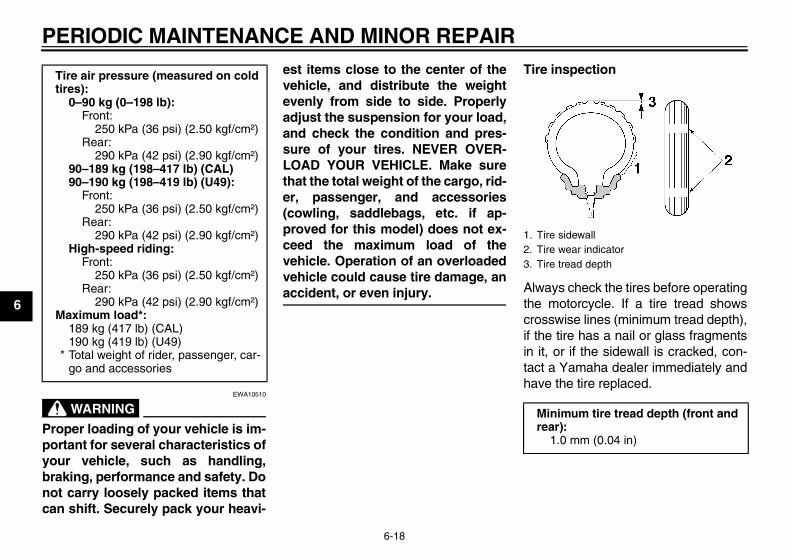
PERIODIC MAINTENANCE AND MINOR REPAIR
6-18
6
WARNINGEWA10510
Proper loading of your vehicle is im-portant for several characteristics ofyour vehicle, such as handling,braking, performance and safety. Donot carry loosely packed items thatcan shift. Securely pack your heavi-
est items close to the center of thevehicle, and distribute the weightevenly from side to side. Properlyadjust the suspension for your load,and check the condition and pres-sure of your tires. NEVER OVER-LOAD YOUR VEHICLE. Make surethat the total weight of the cargo, rid-er, passenger, and accessories(cowling, saddlebags, etc. if ap-proved for this model) does not ex-ceed the maximum load of thevehicle. Operation of an overloadedvehicle could cause tire damage, anaccident, or even injury.
Tire inspection
Always check the tires before operatingthe motorcycle. If a tire tread showscrosswise lines (minimum tread depth),if the tire has a nail or glass fragmentsin it, or if the sidewall is cracked, con-tact a Yamaha dealer immediately andhave the tire replaced.
Tire air pressure (measured on cold tires):
0–90 kg (0–198 lb):Front:
250 kPa (36 psi) (2.50 kgf/cm²)Rear:
290 kPa (42 psi) (2.90 kgf/cm²)90–189 kg (198–417 lb) (CAL)90–190 kg (198–419 lb) (U49):
Front:250 kPa (36 psi) (2.50 kgf/cm²)
Rear:290 kPa (42 psi) (2.90 kgf/cm²)
High-speed riding:Front:
250 kPa (36 psi) (2.50 kgf/cm²)Rear:
290 kPa (42 psi) (2.90 kgf/cm²)Maximum load*:
189 kg (417 lb) (CAL)190 kg (419 lb) (U49)
* Total weight of rider, passenger, car-go and accessories
1. Tire sidewall2. Tire wear indicator3. Tire tread depth
Minimum tire tread depth (front and rear):
1.0 mm (0.04 in)
U3C311E0.book Page 18 Monday, September 11, 2006 1:18 PM
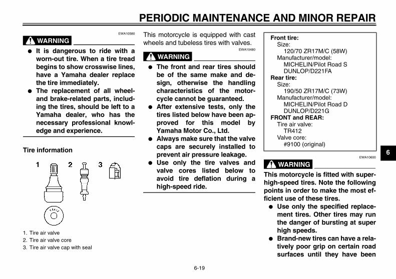
PERIODIC MAINTENANCE AND MINOR REPAIR
6-19
6
WARNINGEWA10580
� It is dangerous to ride with aworn-out tire. When a tire treadbegins to show crosswise lines,have a Yamaha dealer replacethe tire immediately.
� The replacement of all wheel-and brake-related parts, includ-ing the tires, should be left to aYamaha dealer, who has thenecessary professional knowl-edge and experience.
Tire information
This motorcycle is equipped with castwheels and tubeless tires with valves.
WARNINGEWA10480
� The front and rear tires shouldbe of the same make and de-sign, otherwise the handlingcharacteristics of the motor-cycle cannot be guaranteed.
� After extensive tests, only thetires listed below have been ap-proved for this model byYamaha Motor Co., Ltd.
� Always make sure that the valvecaps are securely installed toprevent air pressure leakage.
� Use only the tire valves andvalve cores listed below toavoid tire deflation during ahigh-speed ride.
WARNINGEWA10600
This motorcycle is fitted with super-high-speed tires. Note the followingpoints in order to make the most ef-ficient use of these tires.
� Use only the specified replace-ment tires. Other tires may runthe danger of bursting at superhigh speeds.
� Brand-new tires can have a rela-tively poor grip on certain roadsurfaces until they have been
1. Tire air valve2. Tire air valve core3. Tire air valve cap with seal
Front tire:Size:
120/70 ZR17M/C (58W)Manufacturer/model:
MICHELIN/Pilot Road SDUNLOP/D221FA
Rear tire:Size:
190/50 ZR17M/C (73W)Manufacturer/model:
MICHELIN/Pilot Road DDUNLOP/D221G
FRONT and REAR:Tire air valve:
TR412Valve core:
#9100 (original)
U3C311E0.book Page 19 Monday, September 11, 2006 1:18 PM
PERIODIC MAINTENANCE AND MINOR REPAIR
6-20
6
“broken in”. Therefore, it is ad-visable before doing any high-speed riding to ride conserva-tively for approximately 100 km(60 mi) after installing a new tire.
� The tires must be warmed upbefore a high-speed run.
� Always adjust the tire air pres-sure according to the operatingconditions.
EAU21960
Cast wheels To maximize the performance, durabil-ity, and safe operation of your vehicle,note the following points regarding thespecified wheels.
� The wheel rims should be checkedfor cracks, bends or warpage be-fore each ride. If any damage isfound, have a Yamaha dealer re-place the wheel. Do not attempteven the smallest repair to thewheel. A deformed or crackedwheel must be replaced.
� The wheel should be balancedwhenever either the tire or wheelhas been changed or replaced. Anunbalanced wheel can result inpoor performance, adverse han-dling characteristics, and a short-ened tire life.
� Ride at moderate speeds afterchanging a tire since the tire sur-face must first be “broken in” for itto develop its optimal characteris-tics.
EAU22011
Accessories and replacement parts
WARNINGEWA10621
This vehicle is not designed to pull atrailer or to be attached to a sidecar.The accessories or replacementparts you choose for your vehicleshould be designed specifically forthis model, and they must be se-curely mounted to maintain the in-herent stability of the originaldesign. Genuine Yamaha Parts andAccessories are designed and test-ed to be compatible with your vehi-cle. Please consider GenuineYamaha Parts and Accessories be-fore making a purchase. Use of non-Yamaha-approved accessories orreplacement parts may cause loss ofhandling stability and riding safety.Since Yamaha cannot control thequality of accessories or parts man-ufactured by other companies,Yamaha cannot be held liable for
U3C311E0.book Page 20 Monday, September 11, 2006 1:18 PM
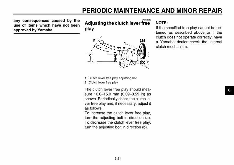
PERIODIC MAINTENANCE AND MINOR REPAIR
6-21
6
any consequences caused by theuse of items which have not beenapproved by Yamaha.
EAU22080
Adjusting the clutch lever free play
The clutch lever free play should mea-sure 10.0–15.0 mm (0.39–0.59 in) asshown. Periodically check the clutch le-ver free play and, if necessary, adjust itas follows.To increase the clutch lever free play,turn the adjusting bolt in direction (a).To decrease the clutch lever free play,turn the adjusting bolt in direction (b).
NOTE:If the specified free play cannot be ob-tained as described above or if theclutch does not operate correctly, havea Yamaha dealer check the internalclutch mechanism.
1. Clutch lever free play adjusting bolt2. Clutch lever free play
U3C311E0.book Page 21 Monday, September 11, 2006 1:18 PM
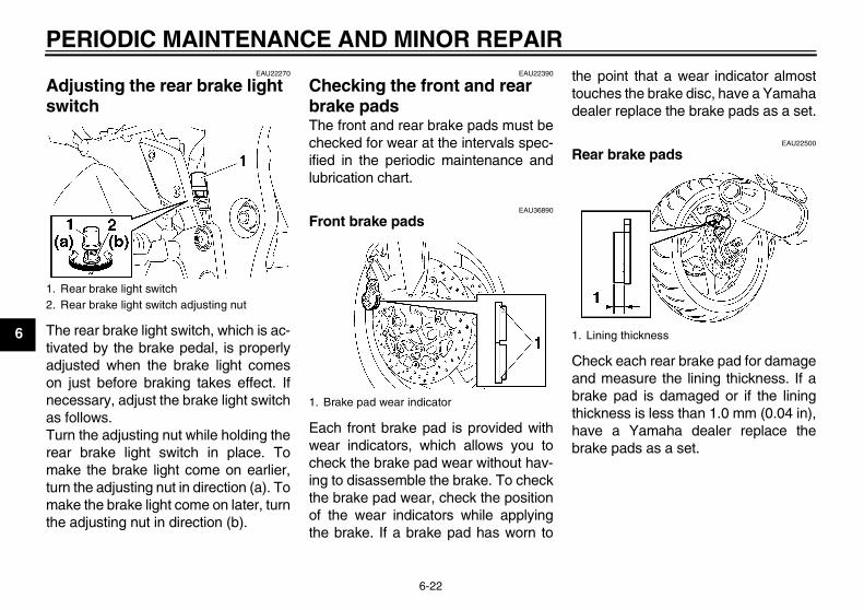
PERIODIC MAINTENANCE AND MINOR REPAIR
6-22
6
EAU22270
Adjusting the rear brake light switch
The rear brake light switch, which is ac-tivated by the brake pedal, is properlyadjusted when the brake light comeson just before braking takes effect. Ifnecessary, adjust the brake light switchas follows.Turn the adjusting nut while holding therear brake light switch in place. Tomake the brake light come on earlier,turn the adjusting nut in direction (a). Tomake the brake light come on later, turnthe adjusting nut in direction (b).
EAU22390
Checking the front and rear brake pads The front and rear brake pads must bechecked for wear at the intervals spec-ified in the periodic maintenance andlubrication chart.
EAU36890
Front brake pads
Each front brake pad is provided withwear indicators, which allows you tocheck the brake pad wear without hav-ing to disassemble the brake. To checkthe brake pad wear, check the positionof the wear indicators while applyingthe brake. If a brake pad has worn to
the point that a wear indicator almosttouches the brake disc, have a Yamahadealer replace the brake pads as a set.
EAU22500
Rear brake pads
Check each rear brake pad for damageand measure the lining thickness. If abrake pad is damaged or if the liningthickness is less than 1.0 mm (0.04 in),have a Yamaha dealer replace thebrake pads as a set.
1. Rear brake light switch2. Rear brake light switch adjusting nut
1. Brake pad wear indicator
1. Lining thickness
U3C311E0.book Page 22 Monday, September 11, 2006 1:18 PM
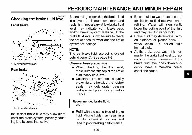
PERIODIC MAINTENANCE AND MINOR REPAIR
6-23
6
EAU22571
Checking the brake fluid level
Front brake
Rear brake
Insufficient brake fluid may allow air toenter the brake system, possibly caus-ing it to become ineffective.
Before riding, check that the brake fluidis above the minimum level mark andreplenish if necessary. A low brake fluidlevel may indicate worn brake padsand/or brake system leakage. If thebrake fluid level is low, be sure to checkthe brake pads for wear and the brakesystem for leakage.
NOTE:The rear brake fluid reservoir is locatedbehind panel C. (See page 6-8.)
Observe these precautions:� When checking the fluid level,
make sure that the top of the brakefluid reservoir is level.
� Use only the recommended qualitybrake fluid, otherwise the rubberseals may deteriorate, causingleakage and poor braking perfor-mance.
� Refill with the same type of brakefluid. Mixing fluids may result in aharmful chemical reaction andlead to poor braking performance.
� Be careful that water does not en-ter the brake fluid reservoir whenrefilling. Water will significantlylower the boiling point of the fluidand may result in vapor lock.
� Brake fluid may deteriorate paint-ed surfaces or plastic parts. Al-ways clean up spilled fluidimmediately.
� As the brake pads wear, it is nor-mal for the brake fluid level to grad-ually go down. However, if thebrake fluid level goes down sud-denly, have a Yamaha dealercheck the cause.
1. Minimum level mark
1. Minimum level mark
Recommended brake fluid:DOT 4
U3C311E0.book Page 23 Monday, September 11, 2006 1:18 PM
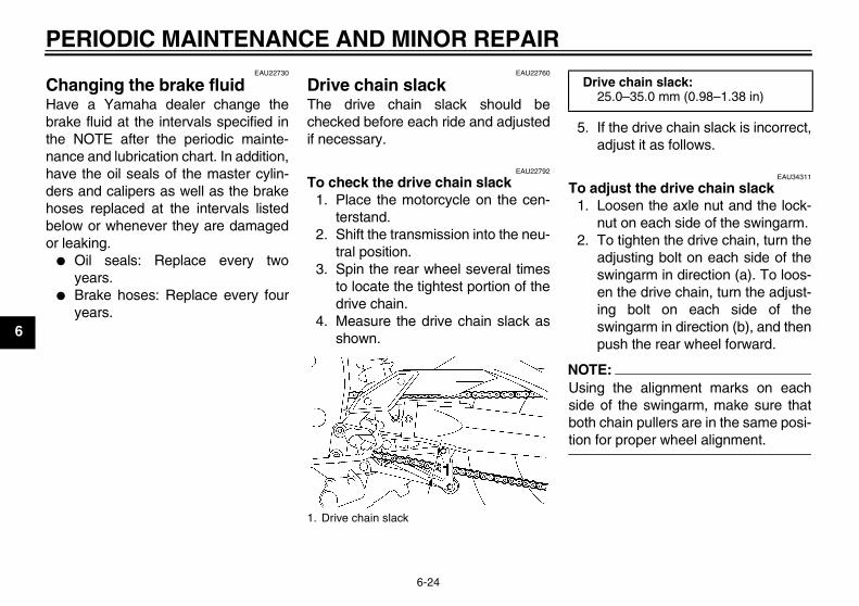
PERIODIC MAINTENANCE AND MINOR REPAIR
6-24
6
EAU22730
Changing the brake fluid Have a Yamaha dealer change thebrake fluid at the intervals specified inthe NOTE after the periodic mainte-nance and lubrication chart. In addition,have the oil seals of the master cylin-ders and calipers as well as the brakehoses replaced at the intervals listedbelow or whenever they are damagedor leaking.
� Oil seals: Replace every twoyears.
� Brake hoses: Replace every fouryears.
EAU22760
Drive chain slack The drive chain slack should bechecked before each ride and adjustedif necessary.
EAU22792
To check the drive chain slack1. Place the motorcycle on the cen-
terstand.2. Shift the transmission into the neu-
tral position.3. Spin the rear wheel several times
to locate the tightest portion of thedrive chain.
4. Measure the drive chain slack asshown.
5. If the drive chain slack is incorrect,adjust it as follows.
EAU34311
To adjust the drive chain slack1. Loosen the axle nut and the lock-
nut on each side of the swingarm.2. To tighten the drive chain, turn the
adjusting bolt on each side of theswingarm in direction (a). To loos-en the drive chain, turn the adjust-ing bolt on each side of theswingarm in direction (b), and thenpush the rear wheel forward.
NOTE:Using the alignment marks on eachside of the swingarm, make sure thatboth chain pullers are in the same posi-tion for proper wheel alignment.
1. Drive chain slack
Drive chain slack:25.0–35.0 mm (0.98–1.38 in)
U3C311E0.book Page 24 Monday, September 11, 2006 1:18 PM
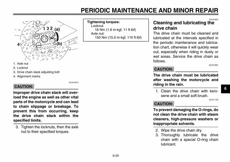
PERIODIC MAINTENANCE AND MINOR REPAIR
6-25
6CAUTION:ECA10570
Improper drive chain slack will over-load the engine as well as other vitalparts of the motorcycle and can leadto chain slippage or breakage. Toprevent this from occurring, keepthe drive chain slack within thespecified limits.
3. Tighten the locknuts, then the axlenut to their specified torques.
EAU23022
Cleaning and lubricating the drive chain The drive chain must be cleaned andlubricated at the intervals specified inthe periodic maintenance and lubrica-tion chart, otherwise it will quickly wearout, especially when riding in dusty orwet areas. Service the drive chain asfollows.
CAUTION:ECA10581
The drive chain must be lubricatedafter washing the motorcycle andriding in the rain.
1. Clean the drive chain with kero-sene and a small soft brush.
CAUTION:ECA11120
To prevent damaging the O-rings, donot clean the drive chain with steamcleaners, high-pressure washers orinappropriate solvents.
2. Wipe the drive chain dry.3. Thoroughly lubricate the drive
chain with a special O-ring chainlubricant.
1. Axle nut2. Locknut3. Drive chain slack adjusting bolt4. Alignment marks
Tightening torques:Locknut:
16 Nm (1.6 m·kgf, 11 ft·lbf)Axle nut:
150 Nm (15.0 m·kgf, 110 ft·lbf)
U3C311E0.book Page 25 Monday, September 11, 2006 1:18 PM
PERIODIC MAINTENANCE AND MINOR REPAIR
6-26
6
CAUTION:ECA11110
Do not use engine oil or any other lu-bricants for the drive chain, as theymay contain substances that coulddamage the O-rings.
EAU23091
Checking and lubricating the cables The operation of all control cables andthe condition of the cables should bechecked before each ride, and the ca-bles and cable ends should be lubricat-ed if necessary. If a cable is damagedor does not move smoothly, have aYamaha dealer check or replace it.
WARNINGEWA10710
Damage to the outer housing of ca-bles may result in internal rustingand cause interference with cablemovement. Replace damaged ca-bles as soon as possible to preventunsafe conditions.
EAU23111
Checking and lubricating the throttle grip and cable The operation of the throttle grip shouldbe checked before each ride. In addi-tion, the cable should be lubricated atthe intervals specified in the periodicmaintenance chart.
Recommended lubricant:Yamaha Chain and Cable Lube or engine oil SAE 10W-30
U3C311E0.book Page 26 Monday, September 11, 2006 1:18 PM
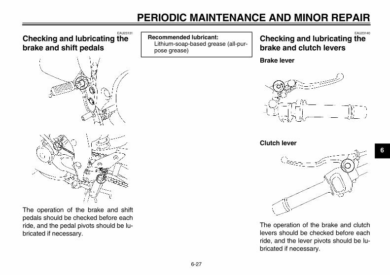
PERIODIC MAINTENANCE AND MINOR REPAIR
6-27
6
EAU23131
Checking and lubricating the brake and shift pedals
The operation of the brake and shiftpedals should be checked before eachride, and the pedal pivots should be lu-bricated if necessary.
EAU23140
Checking and lubricating the brake and clutch levers
Brake lever
Clutch lever
The operation of the brake and clutchlevers should be checked before eachride, and the lever pivots should be lu-bricated if necessary.
Recommended lubricant:Lithium-soap-based grease (all-pur-pose grease)
U3C311E0.book Page 27 Monday, September 11, 2006 1:18 PM
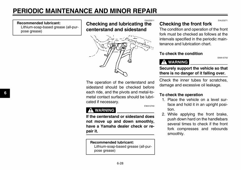
PERIODIC MAINTENANCE AND MINOR REPAIR
6-28
6
EAU23211
Checking and lubricating the centerstand and sidestand
The operation of the centerstand andsidestand should be checked beforeeach ride, and the pivots and metal-to-metal contact surfaces should be lubri-cated if necessary.
WARNINGEWA10740
If the centerstand or sidestand doesnot move up and down smoothly,have a Yamaha dealer check or re-pair it.
EAU23271
Checking the front fork The condition and operation of the frontfork must be checked as follows at theintervals specified in the periodic main-tenance and lubrication chart.
To check the condition
WARNINGEWA10750
Securely support the vehicle so thatthere is no danger of it falling over.
Check the inner tubes for scratches,damage and excessive oil leakage.
To check the operation1. Place the vehicle on a level sur-
face and hold it in an upright posi-tion.
2. While applying the front brake,push down hard on the handlebarsseveral times to check if the frontfork compresses and reboundssmoothly.
Recommended lubricant:Lithium-soap-based grease (all-pur-pose grease)
Recommended lubricant:Lithium-soap-based grease (all-pur-pose grease)
U3C311E0.book Page 28 Monday, September 11, 2006 1:18 PM

PERIODIC MAINTENANCE AND MINOR REPAIR
6-29
6
CAUTION:ECA10590
If any damage is found or the frontfork does not operate smoothly,have a Yamaha dealer check or re-pair it.
EAU23280
Checking the steering Worn or loose steering bearings maycause danger. Therefore, the operationof the steering must be checked as fol-lows at the intervals specified in the pe-riodic maintenance and lubricationchart.
1. Place a stand under the engine toraise the front wheel off theground.
WARNINGEWA10750
Securely support the vehicle so thatthere is no danger of it falling over.
2. Hold the lower ends of the frontfork legs and try to move them for-ward and backward. If any freeplay can be felt, have a Yamahadealer check or repair the steering.
U3C311E0.book Page 29 Monday, September 11, 2006 1:18 PM
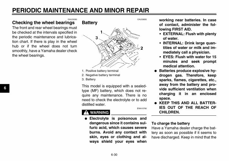
PERIODIC MAINTENANCE AND MINOR REPAIR
6-30
6
EAU23290
Checking the wheel bearings The front and rear wheel bearings mustbe checked at the intervals specified inthe periodic maintenance and lubrica-tion chart. If there is play in the wheelhub or if the wheel does not turnsmoothly, have a Yamaha dealer checkthe wheel bearings.
EAU33650
Battery
This model is equipped with a sealed-type (MF) battery, which does not re-quire any maintenance. There is noneed to check the electrolyte or to adddistilled water.
WARNINGEWA10760
� Electrolyte is poisonous anddangerous since it contains sul-furic acid, which causes severeburns. Avoid any contact withskin, eyes or clothing and al-ways shield your eyes when
working near batteries. In caseof contact, administer the fol-lowing FIRST AID.• EXTERNAL: Flush with plenty
of water.• INTERNAL: Drink large quan-
tities of water or milk and im-mediately call a physician.
• EYES: Flush with water for 15minutes and seek promptmedical attention.
� Batteries produce explosive hy-drogen gas. Therefore, keepsparks, flames, cigarettes, etc.,away from the battery and pro-vide sufficient ventilation whencharging it in an enclosedspace.
� KEEP THIS AND ALL BATTER-IES OUT OF THE REACH OFCHILDREN.
To charge the batteryHave a Yamaha dealer charge the bat-tery as soon as possible if it seems tohave discharged. Keep in mind that the
1. Positive battery terminal2. Negative battery terminal3. Battery
U3C311E0.book Page 30 Monday, September 11, 2006 1:18 PM
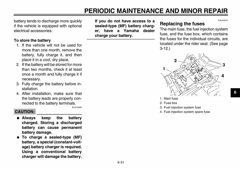
PERIODIC MAINTENANCE AND MINOR REPAIR
6-31
6
battery tends to discharge more quicklyif the vehicle is equipped with optionalelectrical accessories.
To store the battery1. If the vehicle will not be used for
more than one month, remove thebattery, fully charge it, and thenplace it in a cool, dry place.
2. If the battery will be stored for morethan two months, check it at leastonce a month and fully charge it ifnecessary.
3. Fully charge the battery before in-stallation.
4. After installation, make sure thatthe battery leads are properly con-nected to the battery terminals.
CAUTION:ECA10630
� Always keep the batterycharged. Storing a dischargedbattery can cause permanentbattery damage.
� To charge a sealed-type (MF)battery, a special (constant-volt-age) battery charger is required.Using a conventional batterycharger will damage the battery.
If you do not have access to asealed-type (MF) battery charg-er, have a Yamaha dealercharge your battery.
EAU43010
Replacing the fuses The main fuse, the fuel injection systemfuse, and the fuse box, which containsthe fuses for the individual circuits, arelocated under the rider seat. (See page3-12.)
1. Main fuse2. Fuse box3. Fuel injection system fuse4. Fuel injection system spare fuse
U3C311E0.book Page 31 Monday, September 11, 2006 1:18 PM
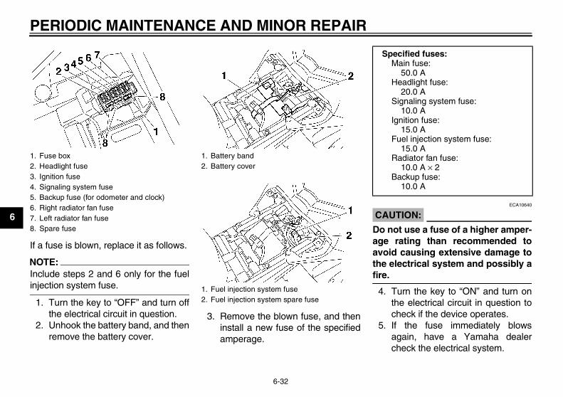
PERIODIC MAINTENANCE AND MINOR REPAIR
6-32
6
If a fuse is blown, replace it as follows.
NOTE:Include steps 2 and 6 only for the fuelinjection system fuse.
1. Turn the key to “OFF” and turn offthe electrical circuit in question.
2. Unhook the battery band, and thenremove the battery cover.
3. Remove the blown fuse, and theninstall a new fuse of the specifiedamperage.
CAUTION:ECA10640
Do not use a fuse of a higher amper-age rating than recommended toavoid causing extensive damage tothe electrical system and possibly afire.
4. Turn the key to “ON” and turn onthe electrical circuit in question tocheck if the device operates.
5. If the fuse immediately blowsagain, have a Yamaha dealercheck the electrical system.
1. Fuse box2. Headlight fuse3. Ignition fuse4. Signaling system fuse5. Backup fuse (for odometer and clock)6. Right radiator fan fuse7. Left radiator fan fuse8. Spare fuse
1. Battery band2. Battery cover
1. Fuel injection system fuse2. Fuel injection system spare fuse
Specified fuses:Main fuse:
50.0 AHeadlight fuse:
20.0 ASignaling system fuse:
10.0 AIgnition fuse:
15.0 AFuel injection system fuse:
15.0 ARadiator fan fuse:
10.0 A × 2Backup fuse:
10.0 A
U3C311E0.book Page 32 Monday, September 11, 2006 1:18 PM
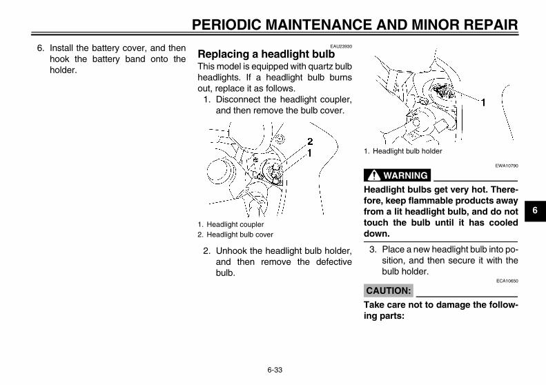
PERIODIC MAINTENANCE AND MINOR REPAIR
6-33
6
6. Install the battery cover, and thenhook the battery band onto theholder.
EAU23930
Replacing a headlight bulb This model is equipped with quartz bulbheadlights. If a headlight bulb burnsout, replace it as follows.
1. Disconnect the headlight coupler,and then remove the bulb cover.
2. Unhook the headlight bulb holder,and then remove the defectivebulb.
WARNINGEWA10790
Headlight bulbs get very hot. There-fore, keep flammable products awayfrom a lit headlight bulb, and do nottouch the bulb until it has cooleddown.
3. Place a new headlight bulb into po-sition, and then secure it with thebulb holder.
CAUTION:ECA10650
Take care not to damage the follow-ing parts:
1. Headlight coupler2. Headlight bulb cover
1. Headlight bulb holder
U3C311E0.book Page 33 Monday, September 11, 2006 1:18 PM
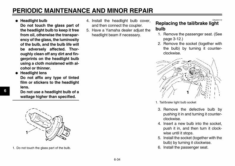
PERIODIC MAINTENANCE AND MINOR REPAIR
6-34
6
� Headlight bulbDo not touch the glass part ofthe headlight bulb to keep it freefrom oil, otherwise the transpar-ency of the glass, the luminosityof the bulb, and the bulb life willbe adversely affected. Thor-oughly clean off any dirt and fin-gerprints on the headlight bulbusing a cloth moistened with al-cohol or thinner.
� Headlight lensDo not affix any type of tintedfilm or stickers to the headlightlens.Do not use a headlight bulb of awattage higher than specified.
4. Install the headlight bulb cover,and then connect the coupler.
5. Have a Yamaha dealer adjust theheadlight beam if necessary.
EAU24112
Replacing the tail/brake light bulb
1. Remove the passenger seat. (Seepage 3-12.)
2. Remove the socket (together withthe bulb) by turning it counter-clockwise.
3. Remove the defective bulb bypushing it in and turning it counter-clockwise.
4. Insert a new bulb into the socket,push it in, and then turn it clock-wise until it stops.
5. Install the socket (together with thebulb) by turning it clockwise.
6. Install the passenger seat.1. Do not touch the glass part of the bulb.
1. Tail/brake light bulb socket
U3C311E0.book Page 34 Monday, September 11, 2006 1:18 PM
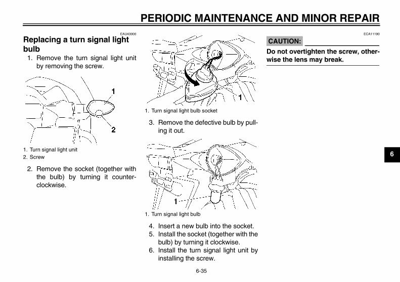
PERIODIC MAINTENANCE AND MINOR REPAIR
6-35
6
EAU43000
Replacing a turn signal light bulb
1. Remove the turn signal light unitby removing the screw.
2. Remove the socket (together withthe bulb) by turning it counter-clockwise.
3. Remove the defective bulb by pull-ing it out.
4. Insert a new bulb into the socket.5. Install the socket (together with the
bulb) by turning it clockwise.6. Install the turn signal light unit by
installing the screw.
CAUTION:ECA11190
Do not overtighten the screw, other-wise the lens may break.
1. Turn signal light unit2. Screw
1. Turn signal light bulb socket
1. Turn signal light bulb
U3C311E0.book Page 35 Monday, September 11, 2006 1:18 PM
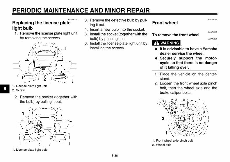
PERIODIC MAINTENANCE AND MINOR REPAIR
6-36
6
EAU24310
Replacing the license plate light bulb
1. Remove the license plate light unitby removing the screws.
2. Remove the socket (together withthe bulb) by pulling it out.
3. Remove the defective bulb by pull-ing it out.
4. Insert a new bulb into the socket.5. Install the socket (together with the
bulb) by pushing it in.6. Install the license plate light unit by
installing the screws.
EAU24360
Front wheel
EAU40200
To remove the front wheel
WARNINGEWA10820
� It is advisable to have a Yamahadealer service the wheel.
� Securely support the motor-cycle so that there is no dangerof it falling over.
1. Place the vehicle on the center-stand.
2. Loosen the front wheel axle pinchbolt, then the wheel axle and thebrake caliper bolts.
1. License plate light unit2. Screw
1. License plate light bulb
1. Front wheel axle pinch bolt2. Wheel axle
U3C311E0.book Page 36 Monday, September 11, 2006 1:18 PM
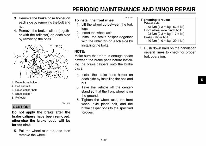
PERIODIC MAINTENANCE AND MINOR REPAIR
6-37
6
3. Remove the brake hose holder oneach side by removing the bolt andnut.
4. Remove the brake caliper (togeth-er with the reflector) on each sideby removing the bolts.
CAUTION:ECA11050
Do not apply the brake after thebrake calipers have been removed,otherwise the brake pads will beforced shut.
5. Pull the wheel axle out, and thenremove the wheel.
EAU40210
To install the front wheel1. Lift the wheel up between the fork
legs.2. Insert the wheel axle.3. Install the brake caliper (together
with the reflector) on each side byinstalling the bolts.
NOTE:Make sure that there is enough spacebetween the brake pads before install-ing the brake calipers onto the brakediscs.
4. Install the brake hose holder oneach side by installing the bolt andnut.
5. Take the vehicle off the center-stand so that the front wheel is onthe ground.
6. Tighten the wheel axle, the frontwheel axle pinch bolt, and thebrake caliper bolts to the specifiedtorques.
7. Push down hard on the handlebarseveral times to check for properfork operation.
1. Brake hose holder2. Bolt and nut3. Brake caliper bolt4. Brake caliper5. Reflector
Tightening torques:Wheel axle:
72 Nm (7.2 m·kgf, 52 ft·lbf)Front wheel axle pinch bolt:
23 Nm (2.3 m·kgf, 17 ft·lbf)Brake caliper bolt:
40 Nm (4.0 m·kgf, 29 ft·lbf)
U3C311E0.book Page 37 Monday, September 11, 2006 1:18 PM
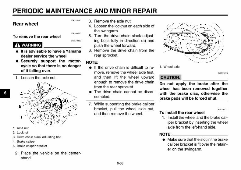
PERIODIC MAINTENANCE AND MINOR REPAIR
6-38
6
EAU25080
Rear wheel
EAU40020
To remove the rear wheel
WARNINGEWA10820
� It is advisable to have a Yamahadealer service the wheel.
� Securely support the motor-cycle so that there is no dangerof it falling over.
1. Loosen the axle nut.
2. Place the vehicle on the center-stand.
3. Remove the axle nut.4. Loosen the locknut on each side of
the swingarm.5. Turn the drive chain slack adjust-
ing bolts fully in direction (a) andpush the wheel forward.
6. Remove the drive chain from therear sprocket.
NOTE:� If the drive chain is difficult to re-
move, remove the wheel axle first,and then lift the wheel upwardenough to remove the drive chainfrom the rear sprocket.
� The drive chain cannot be disas-sembled.
7. While supporting the brake caliperbracket, pull the wheel axle out,and then remove the wheel.
CAUTION:ECA11070
Do not apply the brake after thewheel has been removed togetherwith the brake disc, otherwise thebrake pads will be forced shut.
EAU39411
To install the rear wheel1. Install the wheel and the brake cal-
iper bracket by inserting the wheelaxle from the left-hand side.
NOTE:� Make sure that the slot in the brake
caliper bracket is fit over the retain-er on the swingarm.
1. Axle nut2. Locknut3. Drive chain slack adjusting bolt4. Brake caliper5. Brake caliper bracket
1. Wheel axle
U3C311E0.book Page 38 Monday, September 11, 2006 1:18 PM
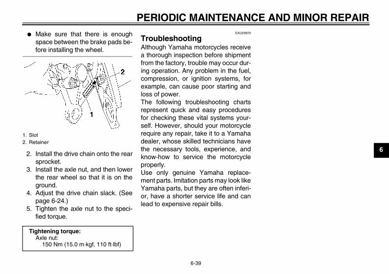
PERIODIC MAINTENANCE AND MINOR REPAIR
6-39
6
� Make sure that there is enoughspace between the brake pads be-fore installing the wheel.
2. Install the drive chain onto the rearsprocket.
3. Install the axle nut, and then lowerthe rear wheel so that it is on theground.
4. Adjust the drive chain slack. (Seepage 6-24.)
5. Tighten the axle nut to the speci-fied torque.
EAU25870
Troubleshooting Although Yamaha motorcycles receivea thorough inspection before shipmentfrom the factory, trouble may occur dur-ing operation. Any problem in the fuel,compression, or ignition systems, forexample, can cause poor starting andloss of power.The following troubleshooting chartsrepresent quick and easy proceduresfor checking these vital systems your-self. However, should your motorcyclerequire any repair, take it to a Yamahadealer, whose skilled technicians havethe necessary tools, experience, andknow-how to service the motorcycleproperly.Use only genuine Yamaha replace-ment parts. Imitation parts may look likeYamaha parts, but they are often inferi-or, have a shorter service life and canlead to expensive repair bills.
1. Slot2. Retainer
Tightening torque:Axle nut:
150 Nm (15.0 m·kgf, 110 ft·lbf)
U3C311E0.book Page 39 Monday, September 11, 2006 1:18 PM
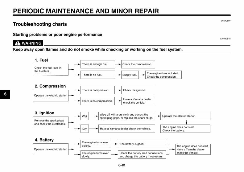
PERIODIC MAINTENANCE AND MINOR REPAIR
6-40
6
EAU42500
Troubleshooting charts
Starting problems or poor engine performance
WARNINGEWA10840
Keep away open flames and do not smoke while checking or working on the fuel system.
Check the fuel level inthe fuel tank.
1. FuelThere is enough fuel.
There is no fuel.
Check the compression.
Supply fuel. The engine does not start. Check the compression.
Operate the electric starter.
2. CompressionThere is compression.
There is no compression.
Check the ignition.
Have a Yamaha dealercheck the vehicle.
Remove the spark plugsand check the electrodes.
3. Ignition Wipe off with a dry cloth and correct thespark plug gaps, or replace the spark plugs.
Have a Yamaha dealer check the vehicle.
The engine does not start.Have a Yamaha dealercheck the vehicle.
The engine does not start.Check the battery.
Operate the electric starter.
4. BatteryThe engine turns over quickly.
The engine turns over slowly.
The battery is good.
Check the battery lead connections,and charge the battery if necessary.
Dry
Wet Operate the electric starter.
U3C311E0.book Page 40 Monday, September 11, 2006 1:18 PM
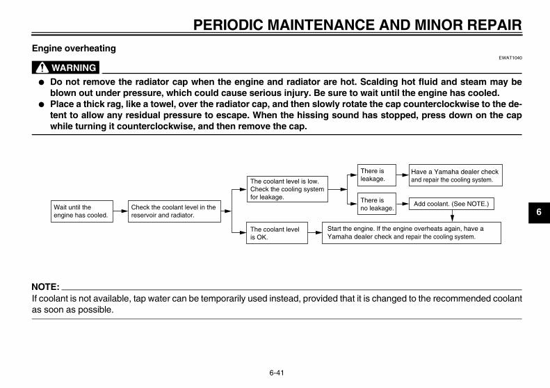
PERIODIC MAINTENANCE AND MINOR REPAIR
6-41
6
Engine overheating
WARNINGEWAT1040
� Do not remove the radiator cap when the engine and radiator are hot. Scalding hot fluid and steam may beblown out under pressure, which could cause serious injury. Be sure to wait until the engine has cooled.
� Place a thick rag, like a towel, over the radiator cap, and then slowly rotate the cap counterclockwise to the de-tent to allow any residual pressure to escape. When the hissing sound has stopped, press down on the capwhile turning it counterclockwise, and then remove the cap.
NOTE:If coolant is not available, tap water can be temporarily used instead, provided that it is changed to the recommended coolantas soon as possible.
Wait until the engine has cooled.
Check the coolant level in the reservoir and radiator.
The coolant level is OK.
The coolant level is low.Check the cooling systemfor leakage.
Have a Yamaha dealer checkand repair the cooling system.
Add coolant. (See NOTE.)
Start the engine. If the engine overheats again, have a Yamaha dealer check and repair the cooling system.
There isleakage.
There is no leakage.
U3C311E0.book Page 41 Monday, September 11, 2006 1:18 PM
MOTORCYCLE CARE AND STORAGE
7-1
7
EAU37833
Matte color caution
CAUTION:ECA15192
Some models are equipped withmatte colored finished parts. Besure to consult a Yamaha dealer foradvice on what products to use be-fore cleaning the vehicle. Using abrush, harsh chemical products orcleaning compounds when cleaningthese parts will scratch or damagetheir surface. Wax also should notbe applied to any matte colored fin-ished parts.
EAU26011
Care While the open design of a motorcyclereveals the attractiveness of the tech-nology, it also makes it more vulnera-ble. Rust and corrosion can developeven if high-quality components areused. A rusty exhaust pipe may go un-noticed on a car, however, it detractsfrom the overall appearance of a motor-cycle. Frequent and proper care doesnot only comply with the terms of thewarranty, but it will also keep yourmotorcycle looking good, extend its lifeand optimize its performance.
Before cleaning1. Cover the muffler outlet with a
plastic bag after the engine hascooled down.
2. Make sure that all caps and coversas well as all electrical couplersand connectors, including thespark plug caps, are tightly in-stalled.
3. Remove extremely stubborn dirt,like oil burnt onto the crankcase,with a degreasing agent and abrush, but never apply such prod-
ucts onto seals, gaskets, sprock-ets, the drive chain and wheelaxles. Always rinse the dirt and de-greaser off with water.
Cleaning
CAUTION:ECA10770
� Avoid using strong acidic wheelcleaners, especially on spokedwheels. If such products areused on hard-to-remove dirt, donot leave the cleaner on the af-fected area any longer than in-structed. Also, thoroughly rinsethe area off with water, immedi-ately dry it, and then apply a cor-rosion protection spray.
� Improper cleaning can damagewindshields, cowlings, panelsand other plastic parts. Use onlya soft, clean cloth or spongewith mild detergent and water toclean plastic.
� Do not use any harsh chemicalproducts on plastic parts. Besure to avoid using cloths orsponges which have been incontact with strong or abrasive
U3C311E0.book Page 1 Monday, September 11, 2006 1:18 PM
MOTORCYCLE CARE AND STORAGE
7-2
7
cleaning products, solvent orthinner, fuel (gasoline), rust re-movers or inhibitors, brake flu-id, antifreeze or electrolyte.
� Do not use high-pressure wash-ers or steam-jet cleaners sincethey cause water seepage anddeterioration in the following ar-eas: seals (of wheel and swing-arm bearings, fork and brakes),electric components (couplers,connectors, instruments,switches and lights), breatherhoses and vents.
� For motorcycles equipped witha windshield: Do not use strongcleaners or hard sponges asthey will cause dulling orscratching. Some cleaning com-pounds for plastic may leavescratches on the windshield.Test the product on a small hid-den part of the windshield tomake sure that it does not leaveany marks. If the windshield isscratched, use a quality plasticpolishing compound afterwashing.
After normal useRemove dirt with warm water, a milddetergent, and a soft, clean sponge,and then rinse thoroughly with cleanwater. Use a toothbrush or bottlebrushfor hard-to-reach areas. Stubborn dirtand insects will come off more easily ifthe area is covered with a wet cloth fora few minutes before cleaning.
After riding in the rain, near the sea oron salt-sprayed roadsSince sea salt or salt sprayed on roadsduring winter are extremely corrosive incombination with water, carry out thefollowing steps after each ride in therain, near the sea or on salt-sprayedroads.
NOTE:Salt sprayed on roads in the winter mayremain well into spring.
1. Clean the motorcycle with cold wa-ter and a mild detergent, after theengine has cooled down.
CAUTION:ECA10790
Do not use warm water since it in-creases the corrosive action of thesalt.
2. Apply a corrosion protection sprayon all metal, including chrome- andnickel-plated, surfaces to preventcorrosion.
After cleaning1. Dry the motorcycle with a chamois
or an absorbing cloth.2. Immediately dry the drive chain
and lubricate it to prevent it fromrusting.
3. Use a chrome polish to shinechrome, aluminum and stainless-steel parts, including the exhaustsystem. (Even the thermally in-duced discoloring of stainless-steel exhaust systems can be re-moved through polishing.)
4. To prevent corrosion, it is recom-mended to apply a corrosion pro-tection spray on all metal,including chrome- and nickel-plat-ed, surfaces.
U3C311E0.book Page 2 Monday, September 11, 2006 1:18 PM
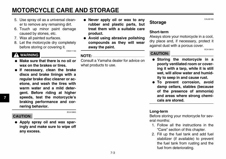
MOTORCYCLE CARE AND STORAGE
7-3
7
5. Use spray oil as a universal clean-er to remove any remaining dirt.
6. Touch up minor paint damagecaused by stones, etc.
7. Wax all painted surfaces.8. Let the motorcycle dry completely
before storing or covering it.
WARNINGEWA11130
� Make sure that there is no oil orwax on the brakes or tires.
� If necessary, clean the brakediscs and brake linings with aregular brake disc cleaner or ac-etone, and wash the tires withwarm water and a mild deter-gent. Before riding at higherspeeds, test the motorcycle’sbraking performance and cor-nering behavior.
CAUTION:ECA10800
� Apply spray oil and wax spar-ingly and make sure to wipe offany excess.
� Never apply oil or wax to anyrubber and plastic parts, buttreat them with a suitable careproduct.
� Avoid using abrasive polishingcompounds as they will wearaway the paint.
NOTE:Consult a Yamaha dealer for advice onwhat products to use.
EAU26180
Storage
Short-termAlways store your motorcycle in a cool,dry place and, if necessary, protect itagainst dust with a porous cover.
CAUTION:ECA10810
� Storing the motorcycle in apoorly ventilated room or cover-ing it with a tarp, while it is stillwet, will allow water and humid-ity to seep in and cause rust.
� To prevent corrosion, avoiddamp cellars, stables (becauseof the presence of ammonia)and areas where strong chemi-cals are stored.
Long-termBefore storing your motorcycle for sev-eral months:
1. Follow all the instructions in the“Care” section of this chapter.
2. Fill up the fuel tank and add fuelstabilizer (if available) to preventthe fuel tank from rusting and thefuel from deteriorating.
U3C311E0.book Page 3 Monday, September 11, 2006 1:18 PM
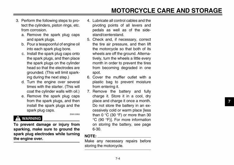
MOTORCYCLE CARE AND STORAGE
7-4
7
3. Perform the following steps to pro-tect the cylinders, piston rings, etc.from corrosion.a. Remove the spark plug caps
and spark plugs.b. Pour a teaspoonful of engine oil
into each spark plug bore.c. Install the spark plug caps onto
the spark plugs, and then placethe spark plugs on the cylinderhead so that the electrodes aregrounded. (This will limit spark-ing during the next step.)
d. Turn the engine over severaltimes with the starter. (This willcoat the cylinder walls with oil.)
e. Remove the spark plug capsfrom the spark plugs, and theninstall the spark plugs and thespark plug caps.
WARNINGEWA10950
To prevent damage or injury fromsparking, make sure to ground thespark plug electrodes while turningthe engine over.
4. Lubricate all control cables and thepivoting points of all levers andpedals as well as of the side-stand/centerstand.
5. Check and, if necessary, correctthe tire air pressure, and then liftthe motorcycle so that both of itswheels are off the ground. Alterna-tively, turn the wheels a little everymonth in order to prevent the tiresfrom becoming degraded in onespot.
6. Cover the muffler outlet with aplastic bag to prevent moisturefrom entering it.
7. Remove the battery and fullycharge it. Store it in a cool, dryplace and charge it once a month.Do not store the battery in an ex-cessively cold or warm place [lessthan 0 °C (30 °F) or more than 30°C (90 °F)]. For more informationon storing the battery, see page6-30.
NOTE:Make any necessary repairs beforestoring the motorcycle.
U3C311E0.book Page 4 Monday, September 11, 2006 1:18 PM
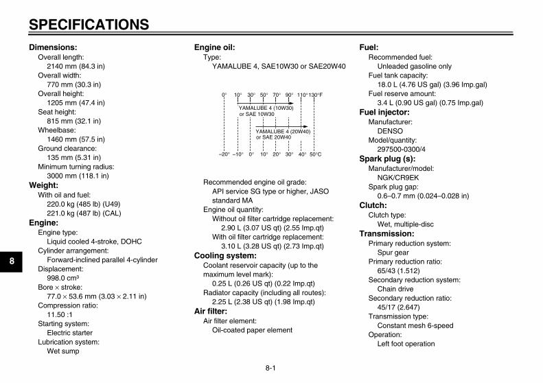
SPECIFICATIONS
8-1
8
Dimensions:Overall length:
2140 mm (84.3 in)Overall width:
770 mm (30.3 in)Overall height:
1205 mm (47.4 in)Seat height:
815 mm (32.1 in)Wheelbase:
1460 mm (57.5 in)Ground clearance:
135 mm (5.31 in)Minimum turning radius:
3000 mm (118.1 in)Weight:
With oil and fuel:220.0 kg (485 lb) (U49)221.0 kg (487 lb) (CAL)
Engine:Engine type:
Liquid cooled 4-stroke, DOHCCylinder arrangement:
Forward-inclined parallel 4-cylinderDisplacement:
998.0 cm³Bore × stroke:
77.0 × 53.6 mm (3.03 × 2.11 in)Compression ratio:
11.50 :1Starting system:
Electric starterLubrication system:
Wet sump
Engine oil:Type:
YAMALUBE 4, SAE10W30 or SAE20W40
Recommended engine oil grade:API service SG type or higher, JASO standard MA
Engine oil quantity:Without oil filter cartridge replacement:
2.90 L (3.07 US qt) (2.55 Imp.qt)With oil filter cartridge replacement:
3.10 L (3.28 US qt) (2.73 Imp.qt)Cooling system:
Coolant reservoir capacity (up to the maximum level mark):
0.25 L (0.26 US qt) (0.22 Imp.qt)Radiator capacity (including all routes):
2.25 L (2.38 US qt) (1.98 Imp.qt)Air filter:
Air filter element:Oil-coated paper element
Fuel:Recommended fuel:
Unleaded gasoline onlyFuel tank capacity:
18.0 L (4.76 US gal) (3.96 Imp.gal)Fuel reserve amount:
3.4 L (0.90 US gal) (0.75 Imp.gal)Fuel injector:
Manufacturer:DENSO
Model/quantity:297500-0300/4
Spark plug (s):Manufacturer/model:
NGK/CR9EKSpark plug gap:
0.6–0.7 mm (0.024–0.028 in)Clutch:
Clutch type:Wet, multiple-disc
Transmission:Primary reduction system:
Spur gearPrimary reduction ratio:
65/43 (1.512)Secondary reduction system:
Chain driveSecondary reduction ratio:
45/17 (2.647)Transmission type:
Constant mesh 6-speedOperation:
Left foot operation
10° 30° 50° 70° 90° 110°0° 130°F
YAMALUBE 4 (10W30)or SAE 10W30
YAMALUBE 4 (20W40)or SAE 20W40
–10° 0° 10° 20° 30° 40°–20° 50°C
U3C311E0.book Page 1 Monday, September 11, 2006 1:18 PM
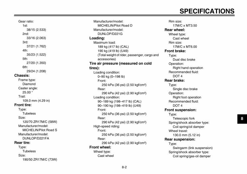
SPECIFICATIONS
8-2
8
Gear ratio:1st:
38/15 (2.533)2nd:
33/16 (2.063)3rd:
37/21 (1.762)4th:
35/23 (1.522)5th:
27/20 (1.350)6th:
29/24 (1.208)Chassis:
Frame type:Diamond
Caster angle:25.00 °
Trail:109.0 mm (4.29 in)
Front tire:Type:
TubelessSize:
120/70 ZR17M/C (58W)Manufacturer/model:
MICHELIN/Pilot Road SManufacturer/model:
DUNLOP/D221FARear tire:
Type:Tubeless
Size:190/50 ZR17M/C (73W)
Manufacturer/model:MICHELIN/Pilot Road D
Manufacturer/model:DUNLOP/D221G
Loading:Maximum load:
189 kg (417 lb) (CAL)190 kg (419 lb) (U49)(Total weight of rider, passenger, cargo and accessories)
Tire air pressure (measured on cold tires):
Loading condition:0–90 kg (0–198 lb)Front:
250 kPa (36 psi) (2.50 kgf/cm²)Rear:
290 kPa (42 psi) (2.90 kgf/cm²)Loading condition:
90–189 kg (198–417 lb) (CAL)90–190 kg (198–419 lb) (U49)Front:
250 kPa (36 psi) (2.50 kgf/cm²)Rear:
290 kPa (42 psi) (2.90 kgf/cm²)High-speed riding:
Front:250 kPa (36 psi) (2.50 kgf/cm²)
Rear:290 kPa (42 psi) (2.90 kgf/cm²)
Front wheel:Wheel type:
Cast wheel
Rim size:17M/C x MT3.50
Rear wheel:Wheel type:
Cast wheelRim size:
17M/C x MT6.00Front brake:
Type:Dual disc brake
Operation:Right hand operation
Recommended fluid:DOT 4
Rear brake:Type:
Single disc brakeOperation:
Right foot operationRecommended fluid:
DOT 4Front suspension:
Type:Telescopic fork
Spring/shock absorber type:Coil spring/oil damper
Wheel travel:130.0 mm (5.12 in)
Rear suspension:Type:
Swingarm (link suspension)Spring/shock absorber type:
Coil spring/gas-oil damper
U3C311E0.book Page 2 Monday, September 11, 2006 1:18 PM
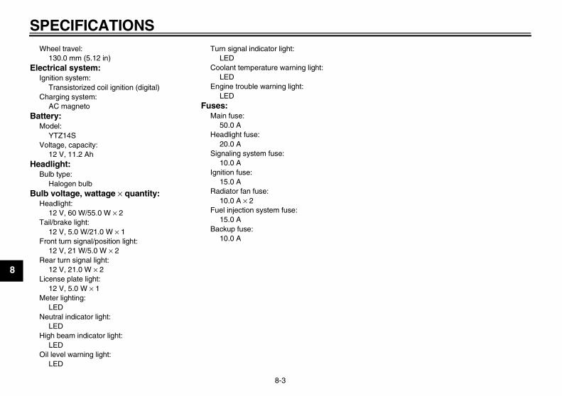
SPECIFICATIONS
8-3
8
Wheel travel:130.0 mm (5.12 in)
Electrical system:Ignition system:
Transistorized coil ignition (digital)Charging system:
AC magnetoBattery:
Model:YTZ14S
Voltage, capacity:12 V, 11.2 Ah
Headlight:Bulb type:
Halogen bulbBulb voltage, wattage × quantity:
Headlight:12 V, 60 W/55.0 W × 2
Tail/brake light:12 V, 5.0 W/21.0 W × 1
Front turn signal/position light:12 V, 21 W/5.0 W × 2
Rear turn signal light:12 V, 21.0 W × 2
License plate light:12 V, 5.0 W × 1
Meter lighting:LED
Neutral indicator light:LED
High beam indicator light:LED
Oil level warning light:LED
Turn signal indicator light:LED
Coolant temperature warning light:LED
Engine trouble warning light:LED
Fuses:Main fuse:
50.0 AHeadlight fuse:
20.0 ASignaling system fuse:
10.0 AIgnition fuse:
15.0 ARadiator fan fuse:
10.0 A × 2Fuel injection system fuse:
15.0 ABackup fuse:
10.0 A
U3C311E0.book Page 3 Monday, September 11, 2006 1:18 PM
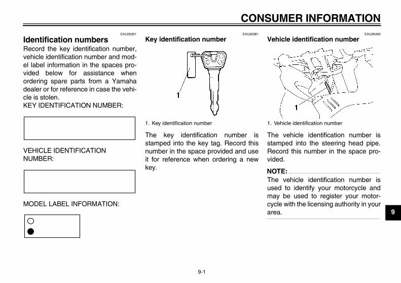
CONSUMER INFORMATION
9-1
9
EAU26351
Identification numbers Record the key identification number,vehicle identification number and mod-el label information in the spaces pro-vided below for assistance whenordering spare parts from a Yamahadealer or for reference in case the vehi-cle is stolen.KEY IDENTIFICATION NUMBER:
VEHICLE IDENTIFICATION NUMBER:
MODEL LABEL INFORMATION:
EAU26381
Key identification number
The key identification number isstamped into the key tag. Record thisnumber in the space provided and useit for reference when ordering a newkey.
EAU26400
Vehicle identification number
The vehicle identification number isstamped into the steering head pipe.Record this number in the space pro-vided.
NOTE:The vehicle identification number isused to identify your motorcycle andmay be used to register your motor-cycle with the licensing authority in yourarea.
1. Key identification number 1. Vehicle identification number
U3C311E0.book Page 1 Monday, September 11, 2006 1:18 PM
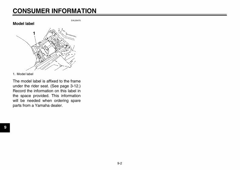
CONSUMER INFORMATION
9-2
9
EAU26470
Model label
The model label is affixed to the frameunder the rider seat. (See page 3-12.)Record the information on this label inthe space provided. This informationwill be needed when ordering spareparts from a Yamaha dealer.
1. Model label
U3C311E0.book Page 2 Monday, September 11, 2006 1:18 PM
CONSUMER INFORMATION
9-3
9
EAU26551
Reporting safety defects If you believe that your vehicle has a defect which could cause a crash or could cause injury or death, you should immediatelyinform the National Highway Traffic Safety Administration (NHTSA) in addition to notifying Yamaha Motor Corporation,U.S.A. If NHTSA receives similar complaints, it may open an investigation, and if it finds that a safety defect exists in a groupof vehicles, it may order a recall and remedy campaign. However, NHTSA cannot become involved in individual problemsbetween you, your dealer, or Yamaha Motor Corporation, U.S.A.To contact NHTSA, you may call the Vehicle Safety Hotline toll-free at 1-888-327-4236 (TTY: 1-800-424-9153); go tohttp://www.safercar.gov; or write to: Administrator, NHTSA, 400 Seventh Street, SW., Washington, DC 20590. You can alsoobtain other information about motor vehicle safety from http://www.safercar.gov.
U3C311E0.book Page 3 Monday, September 11, 2006 1:18 PM
CONSUMER INFORMATION
9-4
9
EAU26560
Motorcycle noise regulation TAMPERING WITH NOISE CONTROL SYSTEM PROHIBITED:Federal law prohibits the following acts or the causing thereof: (1) The removal or rendering inoperative by any person otherthan for purposes of maintenance, repair, or replacement of any device or element of design incorporated into any new ve-hicle for the purpose of noise control prior to its sale or delivery to the ultimate purchaser or while it is in use or (2) the use ofthe vehicle after such device or element of design has been removed or rendered inoperative by any person.“AMONG THOSE ACTS PRESUMED TO CONSTITUTE TAMPERING ARE THE ACTS LISTED BELOW”.These acts include tampering with the following systems; i.e., modification, removal, etc.
Exhaust system• Muffler• Exhaust pipe• Silencer
Intake system• Air cleaner case• Air cleaner element• Intake duct
U3C311E0.book Page 4 Monday, September 11, 2006 1:18 PM
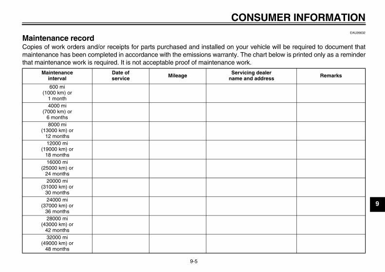
CONSUMER INFORMATION
9-5
9
EAU26632
Maintenance record Copies of work orders and/or receipts for parts purchased and installed on your vehicle will be required to document thatmaintenance has been completed in accordance with the emissions warranty. The chart below is printed only as a reminderthat maintenance work is required. It is not acceptable proof of maintenance work.
Maintenanceinterval
Date ofservice Mileage Servicing dealer
name and address Remarks
600 mi(1000 km) or
1 month4000 mi
(7000 km) or6 months8000 mi
(13000 km) or12 months12000 mi
(19000 km) or18 months16000 mi
(25000 km) or24 months20000 mi
(31000 km) or30 months24000 mi
(37000 km) or36 months28000 mi
(43000 km) or42 months32000 mi
(49000 km) or48 months
U3C311E0.book Page 5 Monday, September 11, 2006 1:18 PM
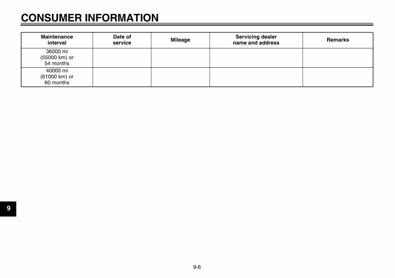
CONSUMER INFORMATION
9-6
9
36000 mi(55000 km) or
54 months40000 mi
(61000 km) or60 months
Maintenanceinterval
Date ofservice Mileage Servicing dealer
name and address Remarks
U3C311E0.book Page 6 Monday, September 11, 2006 1:18 PM
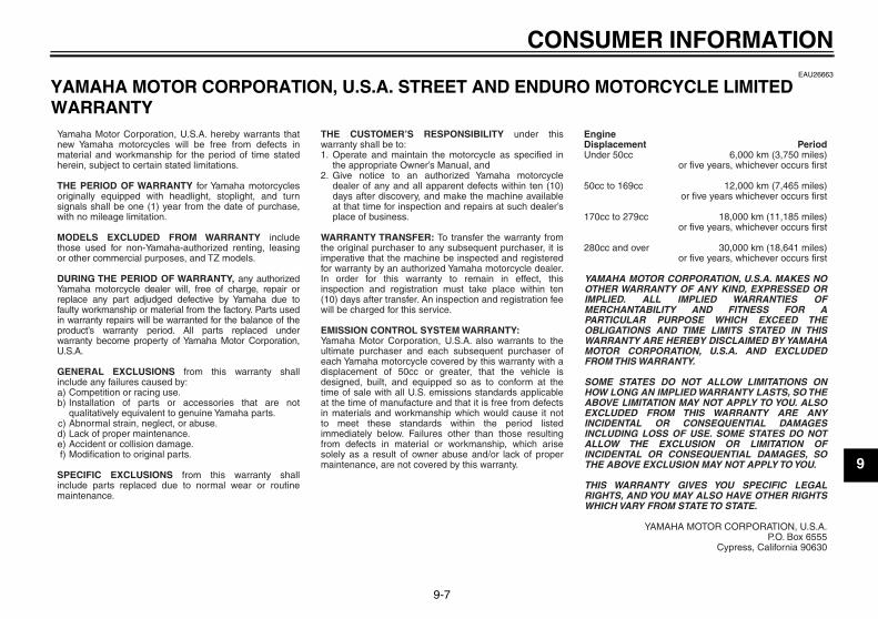
CONSUMER INFORMATION
9-7
9
EAU26663
YAMAHA MOTOR CORPORATION, U.S.A. STREET AND ENDURO MOTORCYCLE LIMITED WARRANTY
a)b)
c)d)e)f)
1.
2.
Yamaha Motor Corporation, U.S.A. hereby warrants that new Yamaha motorcycles will be free from defects in material and workmanship for the period of time stated herein, subject to certain stated limitations.
THE PERIOD OF WARRANTY for Yamaha motorcycles originally equipped with headlight, stoplight, and turn signals shall be one (1) year from the date of purchase, with no mileage limitation.
MODELS EXCLUDED FROM WARRANTY include those used for non-Yamaha-authorized renting, leasing or other commercial purposes, and TZ models.
DURING THE PERIOD OF WARRANTY, any authorized Yamaha motorcycle dealer will, free of charge, repair or replace any part adjudged defective by Yamaha due to faulty workmanship or material from the factory. Parts used in warranty repairs will be warranted for the balance of the product’s warranty period. All parts replaced under warranty become property of Yamaha Motor Corporation, U.S.A.
GENERAL EXCLUSIONS from this warranty shall include any failures caused by:
Competition or racing use.Installation of parts or accessories that are not qualitatively equivalent to genuine Yamaha parts.Abnormal strain, neglect, or abuse.Lack of proper maintenance.Accident or collision damage.Modification to original parts.
SPECIFIC EXCLUSIONS from this warranty shall include parts replaced due to normal wear or routine maintenance.
THE CUSTOMER’S RESPONSIBILITY under this warranty shall be to:
Operate and maintain the motorcycle as specified in the appropriate Owner’s Manual, andGive notice to an authorized Yamaha motorcycle dealer of any and all apparent defects within ten (10) days after discovery, and make the machine available at that time for inspection and repairs at such dealer’s place of business.
WARRANTY TRANSFER: To transfer the warranty from the original purchaser to any subsequent purchaser, it is imperative that the machine be inspected and registered for warranty by an authorized Yamaha motorcycle dealer. In order for this warranty to remain in effect, this inspection and registration must take place within ten (10) days after transfer. An inspection and registration fee will be charged for this service.
EMISSION CONTROL SYSTEM WARRANTY:Yamaha Motor Corporation, U.S.A. also warrants to the ultimate purchaser and each subsequent purchaser of each Yamaha motorcycle covered by this warranty with a displacement of 50cc or greater, that the vehicle is designed, built, and equipped so as to conform at the time of sale with all U.S. emissions standards applicable at the time of manufacture and that it is free from defects in materials and workmanship which would cause it not to meet these standards within the period listed immediately below. Failures other than those resulting from defects in material or workmanship, which arise solely as a result of owner abuse and/or lack of proper maintenance, are not covered by this warranty.
Period6,000 km (3,750 miles)
or five years, whichever occurs first
12,000 km (7,465 miles)or five years whichever occurs first
18,000 km (11,185 miles)or five years, whichever occurs first
30,000 km (18,641 miles)or five years, whichever occurs first
YAMAHA MOTOR CORPORATION, U.S.A. MAKES NO OTHER WARRANTY OF ANY KIND, EXPRESSED OR IMPLIED. ALL IMPLIED WARRANTIES OF MERCHANTABILITY AND FITNESS FOR A PARTICULAR PURPOSE WHICH EXCEED THE OBLIGATIONS AND TIME LIMITS STATED IN THIS WARRANTY ARE HEREBY DISCLAIMED BY YAMAHA MOTOR CORPORATION, U.S.A. AND EXCLUDED FROM THIS WARRANTY.
SOME STATES DO NOT ALLOW LIMITATIONS ON HOW LONG AN IMPLIED WARRANTY LASTS, SO THE ABOVE LIMITATION MAY NOT APPLY TO YOU. ALSO EXCLUDED FROM THIS WARRANTY ARE ANY INCIDENTAL OR CONSEQUENTIAL DAMAGES INCLUDING LOSS OF USE. SOME STATES DO NOT ALLOW THE EXCLUSION OR LIMITATION OF INCIDENTAL OR CONSEQUENTIAL DAMAGES, SO THE ABOVE EXCLUSION MAY NOT APPLY TO YOU.
THIS WARRANTY GIVES YOU SPECIFIC LEGAL RIGHTS, AND YOU MAY ALSO HAVE OTHER RIGHTS WHICH VARY FROM STATE TO STATE.
YAMAHA MOTOR CORPORATION, U.S.A.P.O. Box 6555
Cypress, California 90630
Engine Displacement Under 50cc
50cc to 169cc
170cc to 279cc
280cc and over
U3C311E0.book Page 7 Monday, September 11, 2006 1:18 PM
CONSUMER INFORMATION
9-8
9
WARRANTY QUESTIONS AND ANSWERS
What costs are my responsibility during the warranty period?The customer’s responsibility includes all costs of normal maintenance services, non-warranty repairs, accident and collision damages, and oil, oil filters, air filters, spark plugs, and brake shoes.
What are some examples of “abnormal” strain, neglect, or abuse?These terms are general and overlap each other in areas. Specific examples include: Running the machine out of oil, sustained high rpm, full-throttle, operating the machine with a broken or damaged part which causes another part to fail, damage or failure due to improper or careless transportation and/or tie-down. If you have any specific questions on operation or maintenance, please contact your dealer for advice.
Does the warranty cover incidental costs such as towing or transportation due toa failure?No. The warranty is limited to repair of the machine itself.
May I perform any or all of the recommended maintenance shown in the Owner’s Manual instead of having the dealer do them?Yes, if you are a qualified mechanic and follow the procedures specified in the Owner’s and Service Manual. We do recommend, however, that items requiring special tools or equipment be done by a Yamaha motorcycle dealer.
Will the warranty be void or cancelled if I do not operate or maintain my new motorcycle exactly as specified in the Owner’s Manual?No. The warranty on a new motorcycle cannot be “voided” or “cancelled.” However, if a particular failure is caused by operation or maintenance other than as described in the Owner’s Manual, that failure may not be covered under warranty.
What responsibility does my dealer have under this warranty?Each Yamaha motorcycle dealer is expected to:
Completely set up every new machine before sale.Explain the operation, maintenance, and warranty requirements to your satisfaction at the time of sale, and upon your request at any later date.Each Yamaha motorcycle dealer is held responsible for his setup, service and warranty repair work.
Is the warranty transferable to second owners?Yes. The remainder of the existing warranty can be transferred upon request. The unit has to be inspected and re-registered by an authorized Yamaha motorcycle dealer for the policy to remain effective.
CUSTOMER SERVICE
If your machine requires warranty service, you must take it to any authorized Yamaha motorcycle dealer within the continental United States. Be sure to bring your warranty registration card or other valid proof of the original date of purchase. If a question or problem arises regarding the warranty, first contact the owner of the dealership. Since all warranty matters are handled at the dealer level, this person is in the best position to help you. IF you are still not satisfied and require additional assistance, please write to:
YAMAHA MOTOR CORPORATION, U.S.A.CUSTOMER RELATIONS DEPARTMENT
P.O. Box 6555Cypress, California 90630
When contacting Yamaha Motor Corporation, U.S.A., don’t forget to include any important information such as names, addresses, model, V.I.N. (frame number), dates, and receipts.
CHANGE OF ADDRESS
The federal government requires each manufacturer of a motor vehicle to maintain a complete, up-to-date list of all first purchasers against the possibility of a safety-related defect and recall. This list is compiled from the purchase registrations sent to Yamaha Motor Corporation, U.S.A. by the selling dealer at the time of your purchase.
If you should move after you have purchased your new motorcycle, please advise us of your new address by sending a postcard listing your motorcycle model name, V.I.N. (frame number), dealer number (or dealer’s name) as it is shown on your warranty card, your name and new mailing address. Mail to:
YAMAHA MOTOR CORPORATION, U.S.A.P.O. Box 6555
Cypress, California 90630Attention: Warranty Department
This will ensure that Yamaha Motor Corporation, U.S.A. has an up-to-date registration record in accordance with federal law.
Q.A.
Q.A.
Q.
A.
Q.
A.
Q.
A.
Q.A.
1.2.
3.
Q.A.
U3C311E0.book Page 8 Monday, September 11, 2006 1:18 PM
CONSUMER INFORMATION
9-9
9
EAU26750
YAMAHA EXTENDED SERVICE (Y.E.S.) Keep your Yamaha protected even after your warranty expires with genuine Yamaha Extended Service (Y.E.S.).
Y.E.S. is designed and administered by Yamaha Motor Corporation to provide maximum owner satisfaction. You get uninterrupted factory-backed coverage for extra peace of mind.
Y.E.S. is flexible. You choose the plan that’s right foryou: 12 months, 24 months, 36 months or, on certain models, even 48 months beyond your warranty period.
Y.E.S. is designed and administered by the same Yamaha people who handle your warranty – and itshows in the comprehensive coverage benefits. There are no mileage limitations. Coverage isn’t limited to “moving parts” or the “drive train” like many other plans. And Y.E.S. covers manufacturing defects just like the warranty. See the sample contract at your Yamahadealer to see how comforting uninterrupted factory-backed protection can be.
You don’t have to pay anything for covered repairs. There’s no deductible to pay, and repairs aren’t“pro-rated.” You don’t have any “out-of-pocket” expenses for covered repairs.
In addition, Travel and Recreation Interruption Protection (TRIP) is included at no extra cost. TRIP gives you up to $150 reimbursement per occurrence for any reasonable expenses you incur because your Yamaha needs covered service: replacement vehicle rental, emergency towing, phone calls, even food and lodging when you are away from home. This superb coverage goes into effect when you purchase Y.E.S., so it applies to any warranty repairs as well as covered repairs during your entire Y.E.S. plan period.
Y.E.S. coverage is honored at any authorized Yamaha dealer nationwide.
Y.E.S. coverage is transferable to a new owner if yousell or trade-in. That can make your Yamaha much more valuable!
This excellent Y.E.S. plan coverage is only available to Yamaha owners like you, and only while your Yamaha is still within the Yamaha Limited Warranty period. So visit your authorized Yamaha dealer to get all the facts. He can show you how easy it is to protect your investment with Yamaha Extended Service.
U3C311E0.book Page 9 Monday, September 11, 2006 1:18 PM
CONSUMER INFORMATION
9-10
9
We urge you to act now. You’ll get the excellent benefits of TRIP coverage right away, and you’ll rest easy knowing you’ll have strong factory-backed protection even after your Yamaha Limited Warranty expires.
A special note:If visiting your dealer isn’t convenient, contact Yamaha with your Primary ID number (your frame number). We’ll be happy to help you get the Y.E.S. coverage you need.
Yamaha Service MarketingP.O. Box 6555Cypress, CA 906301-(866)-YES-EXTD (1-866-937-3983)
U3C311E0.book Page 10 Monday, September 11, 2006 1:18 PM
INDEXA
Accessories and replacement parts ..... 6-20Air filter element, replacing ................... 6-15
BBattery .................................................. 6-30Brake and clutch levers, checking
and lubricating .................................... 6-27Brake and shift pedals, checking
and lubricating .................................... 6-27Brake fluid, changing ............................ 6-24Brake fluid level, checking .................... 6-23Brake lever ........................................... 3-10Brake pedal .......................................... 3-10
CCables, checking and lubricating.......... 6-26Canister (for California only)................. 6-10Care........................................................ 7-1Catalytic converter................................ 3-12Centerstand and sidestand, checking
and lubricating .................................... 6-28Clutch lever............................................. 3-9Clutch lever free play, adjusting ........... 6-21Coolant ................................................. 6-13Coolant temperature warning light.......... 3-2
DDimmer switch ........................................ 3-8Drive chain, cleaning and lubricating.... 6-25Drive chain slack .................................. 6-24
EEngine break-in ...................................... 5-4Engine oil and oil filter cartridge ........... 6-10Engine stop switch.................................. 3-8Engine trouble warning light ................... 3-4EXUP system ....................................... 3-18
FFront and rear brake pads, checking ....6-22Front fork, adjusting ..............................3-14Front fork, checking...............................6-28Fuel .......................................................3-11Fuel tank cap.........................................3-10Fuses, replacing....................................6-31
HHandlebar switches.................................3-8Hazard switch..........................................3-9Headlight bulb, replacing.......................6-33High beam indicator light.........................3-2Horn switch .............................................3-8
IIdentification numbers .............................9-1Ignition circuit cut-off system.................3-19Indicator and warning lights ....................3-2
KKey identification number........................9-1
LLabels, location of ...................................1-5License plate light bulb, replacing .........6-36Luggage strap holders ..........................3-18
MMain switch/steering lock ........................3-1Maintenance and lubrication, periodic.....6-4Maintenance, emission control
system...................................................6-3Maintenance, periodic .............................6-1Maintenance record ................................9-5Matte color, caution.................................7-1Model label..............................................9-2Multi-function meter unit..........................3-4
NNeutral indicator light .............................. 3-2Noise regulation...................................... 9-4
OOil level warning light .............................. 3-2
PPanels, removing and installing .............. 6-8Parking.................................................... 5-4Part locations .......................................... 2-1Pre-operation check list .......................... 4-2
RRear brake light switch, adjusting ......... 6-22
SSafety defects, reporting......................... 9-3Safety information................................... 1-1Seats..................................................... 3-12Shifting.................................................... 5-2Shift pedal............................................... 3-9Shock absorber assembly, adjusting .... 3-16Sidestand.............................................. 3-18Spark plugs, checking............................. 6-9Specifications.......................................... 8-1Starting the engine.................................. 5-1Start switch ............................................. 3-8Steering, checking ................................ 6-29Storage ................................................... 7-3Storage compartment ........................... 3-14
TTail/brake light bulb, replacing .............. 6-34Throttle cable free play, checking ......... 6-17Throttle grip and cable, checking
and lubricating .................................... 6-26Tires...................................................... 6-17Tool kit .................................................... 6-1
U3C311E0.book Page 1 Monday, September 11, 2006 1:18 PM
INDEXTroubleshooting .................................... 6-39Troubleshooting charts ......................... 6-40Turn signal indicator lights ...................... 3-2Turn signal light bulb, replacing ............ 6-35Turn signal switch ................................... 3-8
VValve clearance .................................... 6-17Vehicle identification number .................. 9-1
WWarranty, extended................................. 9-9Warranty, limited ..................................... 9-7Wheel bearings, checking..................... 6-30Wheel (front) ......................................... 6-36Wheel (rear) .......................................... 6-38Wheels .................................................. 6-20
U3C311E0.book Page 2 Monday, September 11, 2006 1:18 PM

U3C311E0.book Page 3 Monday, September 11, 2006 1:18 PM
PRINTED IN JAPAN2006.09-0.8×1 CR
(E)
PRINTED ON RECYCLED PAPER YAMAHA MOTOR CO., LTD.