Embed Size (px)
Citation preview
1
Foreword
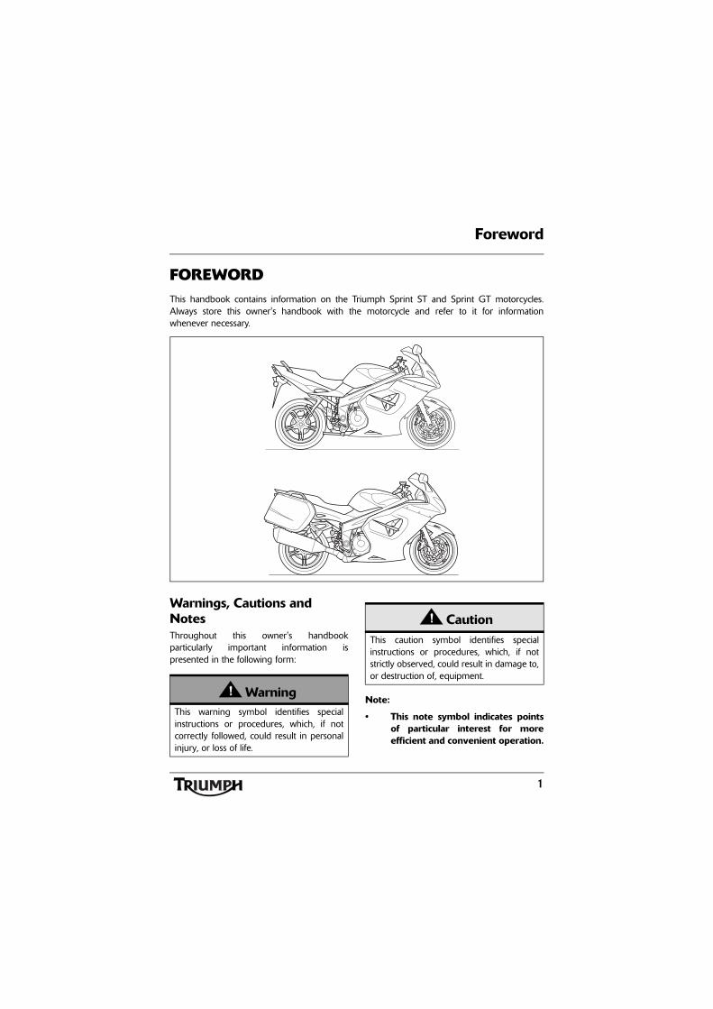
FOREWORDThis handbook contains information on the Triumph Sprint ST and Sprint GT motorcycles.Always store this owner's handbook with the motorcycle and refer to it for informationwhenever necessary.
Warnings, Cautions and NotesThroughout this owner's handbookparticularly important information ispresented in the following form:
Note:
• This note symbol indicates pointsof particular interest for moreefficient and convenient operation.
WarningThis warning symbol identifies specialinstructions or procedures, which, if notcorrectly followed, could result in personalinjury, or loss of life.
CautionThis caution symbol identifies specialinstructions or procedures, which, if notstrictly observed, could result in damage to,or destruction of, equipment.
2
Foreword
Warning LabelsAt certain areas of themotorcycle, the symbol (left)can be seen. The symbolmeans 'CAUTION: REFER TOTHE HANDBOOK' and willbe followed by a pictorialrepresentation of the subject
concerned.
Never attempt to ride the motorcycle ormake any adjustments without reference tothe relevant instructions contained in thishandbook.
See pages 10 and 11 for the location of alllabels bearing this symbol. Where necessary,this symbol will also appear on the pagescontaining the relevant information.
MaintenanceTo ensure a long, safe and trouble free life foryour motorcycle, maintenance should only becarried out by an authorised Triumph dealer.
Only an authorised Triumph dealer will havethe necessary knowledge, equipment andskills to maintain your Triumph motorcyclecorrectly.
To locate your nearest Triumph dealer, visitthe Triumph web site at www.triumph.co.ukor telephone the authorised distributor inyour country. Their address is given in theservice record book that accompanies thishandbook.
Noise Control SystemTampering with the Noise Control System isprohibited.
Owners are warned that the law mayprohibit:
a) The removal or renderinginoperative by any person other thanfor purposes of maintenance, repairor replacement, of any device orelement of design incorporated intoany new vehicle for the purpose ofnoise control prior to its sale ordelivery to the ultimate purchaser orwhile it is in use and,
b) the use of the vehicle after suchdevice or element of design hasbeen removed or renderedinoperative by any person.
3
Foreword
Owner's HandbookThank you for choosing a Triumphmotorcycle. This motorcycle is the product ofTriumph's use of proven engineering,exhaustive testing, and continuous striving forsuperior reliability, safety and performance.
Please read this owner's handbook beforeriding in order to become thoroughly familiarwith the correct operation of yourmotorcycle's controls, its features, capabilitiesand limitations.
This handbook includes safe riding tips, butdoes not contain all the techniques and skillsnecessary to ride a motorcycle safely.
Triumph strongly recommends that all ridersundertake the necessary training to ensuresafe operation of this motorcycle.
This handbook is also available from yourlocal dealer in:
• Dutch;
• French;
• German;
• Italian;
• Japanese;
• Spanish;
• Swedish.
Talk to TriumphOur relationship with you does not end withthe purchase of your Triumph. Your feedbackon the buying and ownership experience isvery important in helping us develop ourproducts and services for you. Please help usby ensuring your dealership has your E-mailaddress and registers this with us. You willthen receive an online customer satisfactionsurvey invitation to your E-mail addresswhere you can give us this feedback.
Your Triumph Team.
WarningThis owner's handbook, and all otherinstructions that are supplied with yourmotorcycle, should be considered apermanent part of your motorcycle andshould remain with it even if yourmotorcycle is subsequently sold.
All riders must read this owner's handbookand all other instructions which aresupplied with your motorcycle, beforeriding, in order to become thoroughlyfamiliar with the correct operation of yourmotorcycle's controls, its features,capabilities and limitations. Do not lendyour motorcycle to others as riding whennot familiar with your motorcycle'scontrols, features, capabilities andlimitations can lead to an accident.
Foreword
4
InformationThe information contained in this publication is based on the latest information available at thetime of printing. Triumph reserves the right to make changes at any time without prior notice, orobligation.
Not to be reproduced wholly or in part without the written permission of Triumph MotorcyclesLimited.
© Copyright 04.2010 Triumph Motorcycles Limited, Hinckley, Leicestershire, England.
Publication part number 3856156 issue 1.
Table of ContentsThis handbook contains a number of different sections. The table of contents below will helpyou find the beginning of each section where, in the case of the major sections, a further tableof contents will help you find the specific subject required.
Foreword. . . . . . . . . . . . . . . . . . . . . . . . . . . . . . . . . . . . . . . . . . . . . . . . . . . . . . . . . . . . . . . . . . . . 1
Warning Labels. . . . . . . . . . . . . . . . . . . . . . . . . . . . . . . . . . . . . . . . . . . . . . . . . . . . . . . . . . . . . . 10
Parts Identification. . . . . . . . . . . . . . . . . . . . . . . . . . . . . . . . . . . . . . . . . . . . . . . . . . . . . . . . . . . . 12
Serial Numbers. . . . . . . . . . . . . . . . . . . . . . . . . . . . . . . . . . . . . . . . . . . . . . . . . . . . . . . . . . . . . . 17
General Information . . . . . . . . . . . . . . . . . . . . . . . . . . . . . . . . . . . . . . . . . . . . . . . . . . . . . . . . . . 19
How to Ride the Motorcycle . . . . . . . . . . . . . . . . . . . . . . . . . . . . . . . . . . . . . . . . . . . . . . . . . . . 49
Accessories, Loading and Passengers . . . . . . . . . . . . . . . . . . . . . . . . . . . . . . . . . . . . . . . . . . . . 61
Maintenance and Adjustment . . . . . . . . . . . . . . . . . . . . . . . . . . . . . . . . . . . . . . . . . . . . . . . . . . 65
Storage . . . . . . . . . . . . . . . . . . . . . . . . . . . . . . . . . . . . . . . . . . . . . . . . . . . . . . . . . . . . . . . . . . . .115
Specifications . . . . . . . . . . . . . . . . . . . . . . . . . . . . . . . . . . . . . . . . . . . . . . . . . . . . . . . . . . . . . . .117
5
Foreword - Safety First
FOREWORD - SAFETY FIRST
The Motorcycle Fuel and Exhaust Fumes
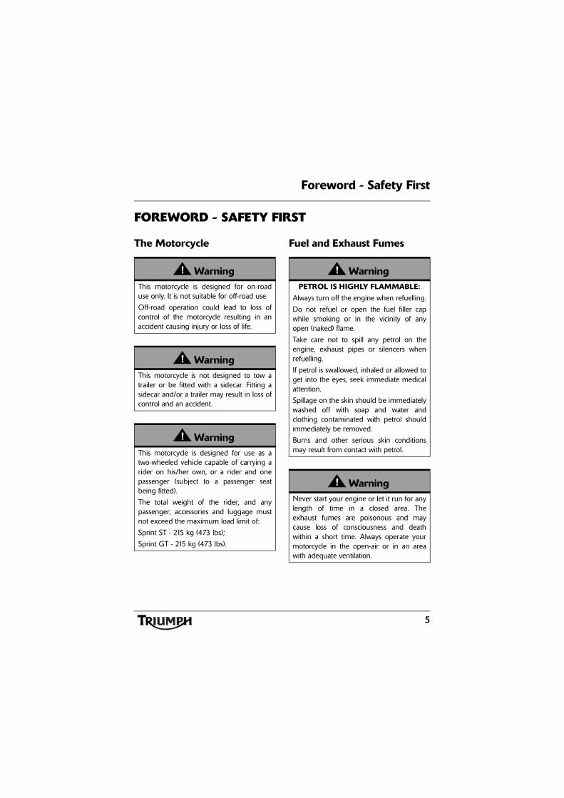
WarningThis motorcycle is designed for on-roaduse only. It is not suitable for off-road use.
Off-road operation could lead to loss ofcontrol of the motorcycle resulting in anaccident causing injury or loss of life.
WarningThis motorcycle is not designed to tow atrailer or be fitted with a sidecar. Fitting asidecar and/or a trailer may result in loss ofcontrol and an accident.
WarningThis motorcycle is designed for use as atwo-wheeled vehicle capable of carrying arider on his/her own, or a rider and onepassenger (subject to a passenger seatbeing fitted).
The total weight of the rider, and anypassenger, accessories and luggage mustnot exceed the maximum load limit of:
Sprint ST - 215 kg (473 lbs);
Sprint GT - 215 kg (473 lbs).
WarningPETROL IS HIGHLY FLAMMABLE:
Always turn off the engine when refuelling.
Do not refuel or open the fuel filler capwhile smoking or in the vicinity of anyopen (naked) flame.
Take care not to spill any petrol on theengine, exhaust pipes or silencers whenrefuelling.
If petrol is swallowed, inhaled or allowed toget into the eyes, seek immediate medicalattention.
Spillage on the skin should be immediatelywashed off with soap and water andclothing contaminated with petrol shouldimmediately be removed.
Burns and other serious skin conditionsmay result from contact with petrol.
WarningNever start your engine or let it run for anylength of time in a closed area. Theexhaust fumes are poisonous and maycause loss of consciousness and deathwithin a short time. Always operate yourmotorcycle in the open-air or in an areawith adequate ventilation.
6
Foreword - Safety First
Riding
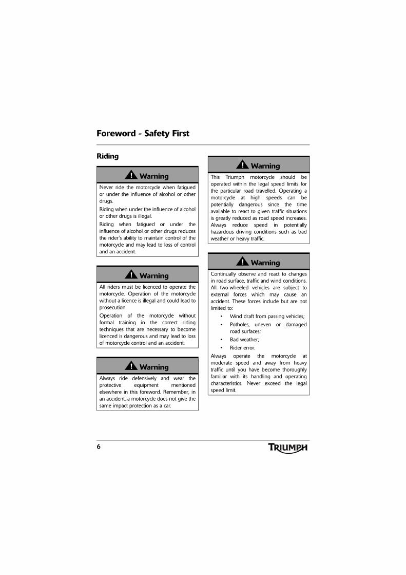
WarningNever ride the motorcycle when fatiguedor under the influence of alcohol or otherdrugs.
Riding when under the influence of alcoholor other drugs is illegal.
Riding when fatigued or under theinfluence of alcohol or other drugs reducesthe rider's ability to maintain control of themotorcycle and may lead to loss of controland an accident.
WarningAll riders must be licenced to operate themotorcycle. Operation of the motorcyclewithout a licence is illegal and could lead toprosecution.
Operation of the motorcycle withoutformal training in the correct ridingtechniques that are necessary to becomelicenced is dangerous and may lead to lossof motorcycle control and an accident.
WarningAlways ride defensively and wear theprotective equipment mentionedelsewhere in this foreword. Remember, inan accident, a motorcycle does not give thesame impact protection as a car.
WarningThis Triumph motorcycle should beoperated within the legal speed limits forthe particular road travelled. Operating amotorcycle at high speeds can bepotentially dangerous since the timeavailable to react to given traffic situationsis greatly reduced as road speed increases.Always reduce speed in potentiallyhazardous driving conditions such as badweather or heavy traffic.
WarningContinually observe and react to changesin road surface, traffic and wind conditions.All two-wheeled vehicles are subject toexternal forces which may cause anaccident. These forces include but are notlimited to:
• Wind draft from passing vehicles;
• Potholes, uneven or damagedroad surfaces;
• Bad weather;
• Rider error.
Always operate the motorcycle atmoderate speed and away from heavytraffic until you have become thoroughlyfamiliar with its handling and operatingcharacteristics. Never exceed the legalspeed limit.
7
Foreword - Safety First
Helmet and Clothing Handlebars and Footrests
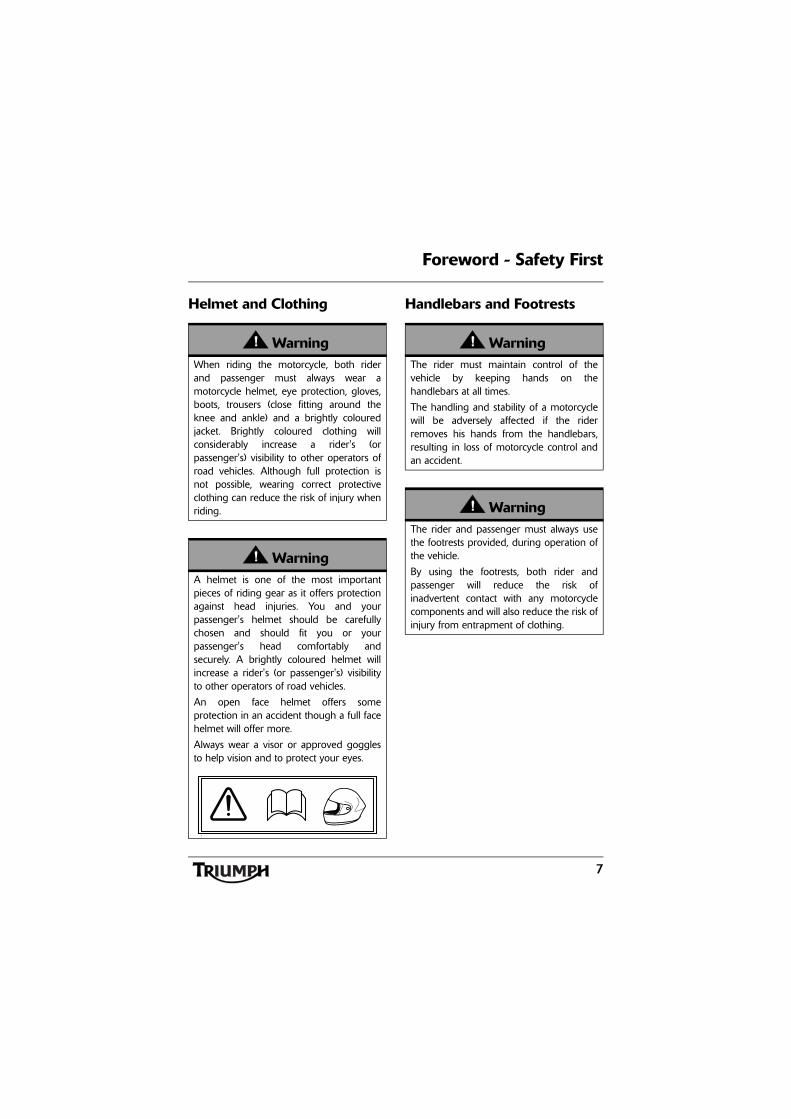
WarningWhen riding the motorcycle, both riderand passenger must always wear amotorcycle helmet, eye protection, gloves,boots, trousers (close fitting around theknee and ankle) and a brightly colouredjacket. Brightly coloured clothing willconsiderably increase a rider's (orpassenger's) visibility to other operators ofroad vehicles. Although full protection isnot possible, wearing correct protectiveclothing can reduce the risk of injury whenriding.
WarningA helmet is one of the most importantpieces of riding gear as it offers protectionagainst head injuries. You and yourpassenger's helmet should be carefullychosen and should fit you or yourpassenger's head comfortably andsecurely. A brightly coloured helmet willincrease a rider's (or passenger's) visibilityto other operators of road vehicles.
An open face helmet offers someprotection in an accident though a full facehelmet will offer more.
Always wear a visor or approved gogglesto help vision and to protect your eyes.
b
WarningThe rider must maintain control of thevehicle by keeping hands on thehandlebars at all times.
The handling and stability of a motorcyclewill be adversely affected if the riderremoves his hands from the handlebars,resulting in loss of motorcycle control andan accident.
WarningThe rider and passenger must always usethe footrests provided, during operation ofthe vehicle.
By using the footrests, both rider andpassenger will reduce the risk ofinadvertent contact with any motorcyclecomponents and will also reduce the risk ofinjury from entrapment of clothing.
8
Foreword - Safety First
Parking Parts and Accessories
Triumph does not accept any liabilitywhatsoever for defects caused by the fittingof non-approved parts, accessories orconversions or the fitting of any approvedparts, accessories or conversions bynon-approved personnel.
WarningAlways turn off the engine and remove theignition key before leaving the motorcycleunattended. By removing the key, the riskof use of the motorcycle by unauthorisedor untrained persons is reduced.
When parking the motorcycle, alwaysremember the following:
Engage first gear to help prevent themotorcycle from rolling off the stand.
The engine and exhaust system will be hotafter riding. DO NOT park wherepedestrians, animals and/or children arelikely to touch the motorcycle.
Do not park on soft ground or on a steeplyinclined surface. Parking under theseconditions may cause the motorcycle to fallover.
For further details, please refer to the 'Howto Ride the Motorcycle' section of thisowner's handbook.
WarningOwners should be aware that the onlyapproved parts, accessories andconversions for any Triumph motorcycleare those which carry official Triumphapproval and are fitted to the motorcycleby an authorised dealer.
In particular, it is extremely hazardous to fitor replace parts or accessories whose fittingrequires the dismantling of, or addition to,either the electrical or fuel systems and anysuch modification could cause a safetyhazard.
The fitting of any non-approved parts,accessories or conversions may adverselyaffect the handling, stability or other aspectof the motorcycle operation that may resultin an accident causing injury or death.
9
Foreword - Safety First
Maintenance/Equipment
WarningConsult your authorised Triumph dealerwhenever there is doubt as to the corrector safe operation of this Triumphmotorcycle.
Remember that continued operation of anincorrectly performing motorcycle mayaggravate a fault and may alsocompromise safety.
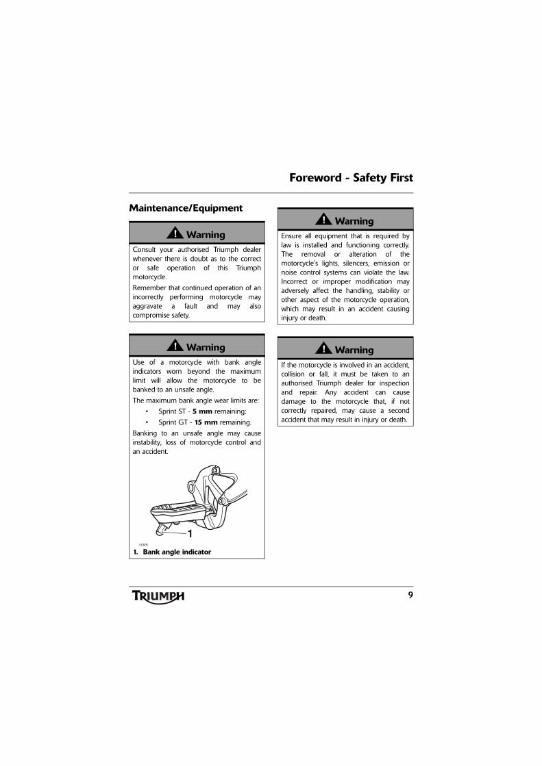
WarningUse of a motorcycle with bank angleindicators worn beyond the maximumlimit will allow the motorcycle to bebanked to an unsafe angle.
The maximum bank angle wear limits are:
• Sprint ST - 5 mm remaining;
• Sprint GT - 15 mm remaining.
Banking to an unsafe angle may causeinstability, loss of motorcycle control andan accident.
1. Bank angle indicatorccsm
1
WarningEnsure all equipment that is required bylaw is installed and functioning correctly.The removal or alteration of themotorcycle's lights, silencers, emission ornoise control systems can violate the law.Incorrect or improper modification mayadversely affect the handling, stability orother aspect of the motorcycle operation,which may result in an accident causinginjury or death.
WarningIf the motorcycle is involved in an accident,collision or fall, it must be taken to anauthorised Triumph dealer for inspectionand repair. Any accident can causedamage to the motorcycle that, if notcorrectly repaired, may cause a secondaccident that may result in injury or death.
Warning Labels
10
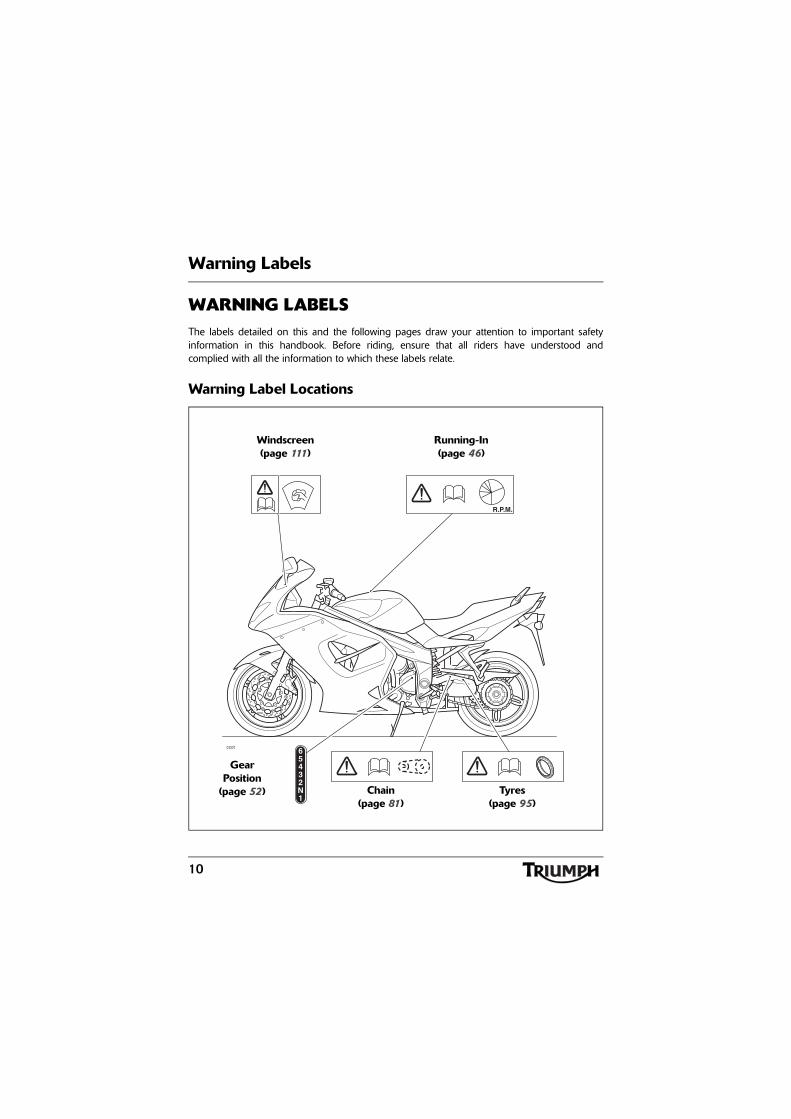
WARNING LABELSThe labels detailed on this and the following pages draw your attention to important safetyinformation in this handbook. Before riding, ensure that all riders have understood andcomplied with all the information to which these labels relate.
Warning Label Locations
ccot65432N1
R.P.M.
Running-In(page 46)
Windscreen(page 111)
Gear Position
(page 52) Chain(page 81)
Tyres(page 95)
Warning Labels
11
WARNING LABELS
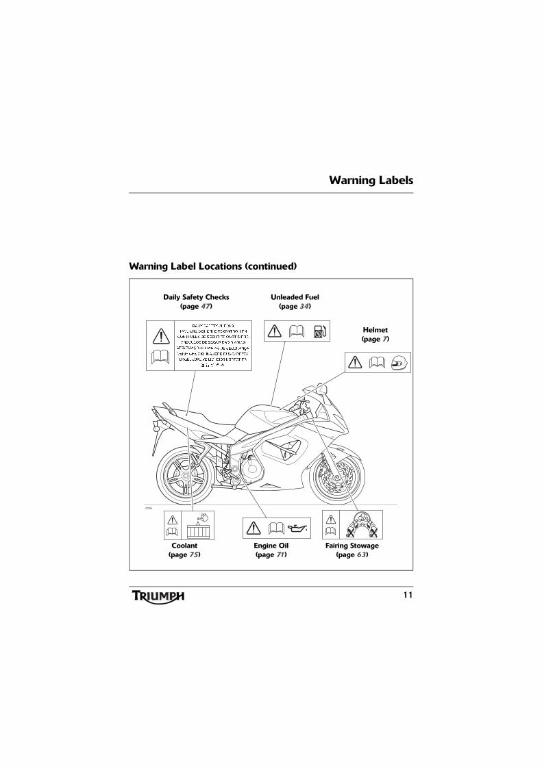
Warning Label Locations (continued)
ccou
Daily Safety Checks(page 47)
Unleaded Fuel(page 34)
Helmet(page 7)
Coolant(page 75)
Engine Oil(page 71)
Fairing Stowage(page 63)
12
Parts Identification
PARTS IDENTIFICATION
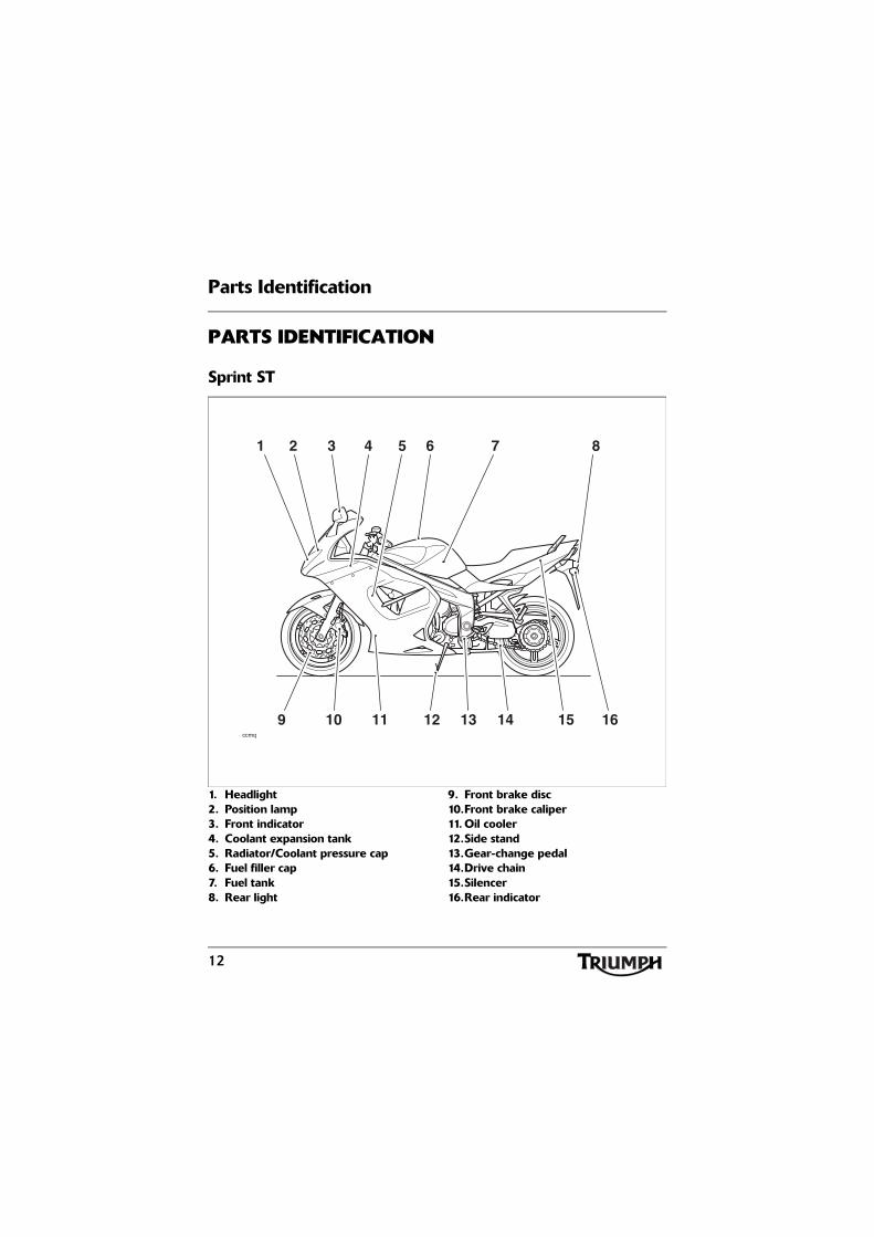
Sprint ST
1. Headlight2. Position lamp3. Front indicator4. Coolant expansion tank5. Radiator/Coolant pressure cap6. Fuel filler cap7. Fuel tank8. Rear light
9. Front brake disc10.Front brake caliper11. Oil cooler12.Side stand13.Gear-change pedal14.Drive chain15.Silencer16.Rear indicator
ccmq
52 6
15
3 74 8
141312 169 10 11
1
13
Parts Identification
PARTS IDENTIFICATION
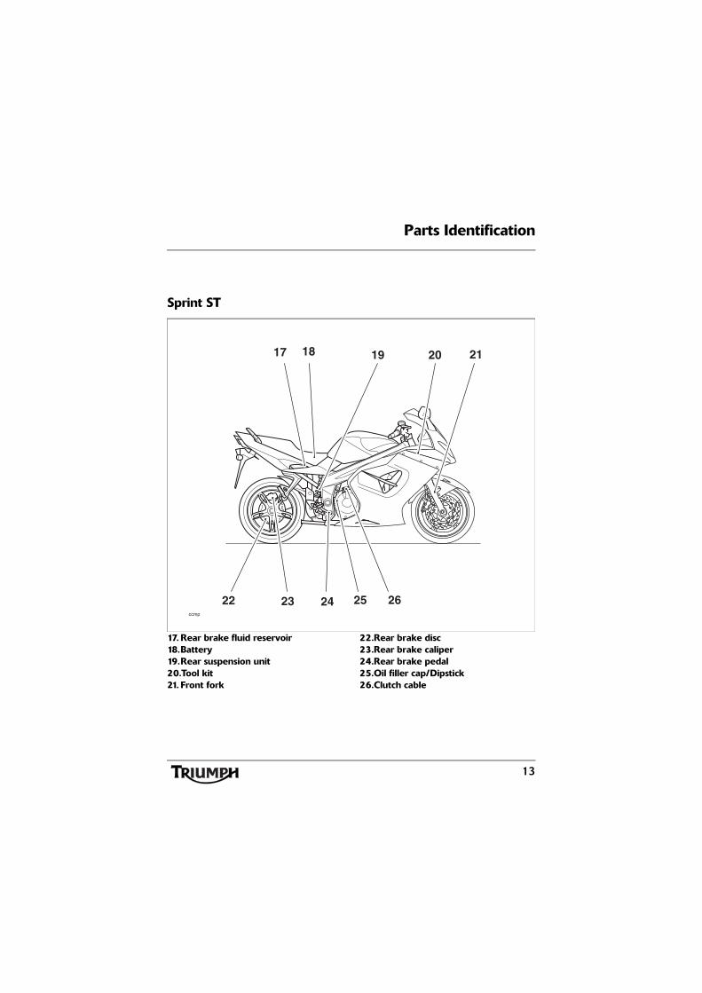
Sprint ST
17. Rear brake fluid reservoir18.Battery19.Rear suspension unit20.Tool kit21. Front fork
22.Rear brake disc23.Rear brake caliper24.Rear brake pedal25.Oil filler cap/Dipstick26.Clutch cable
20
2422
19 21
262523
17
ccmp
18
14
Parts Identification
PARTS IDENTIFICATION
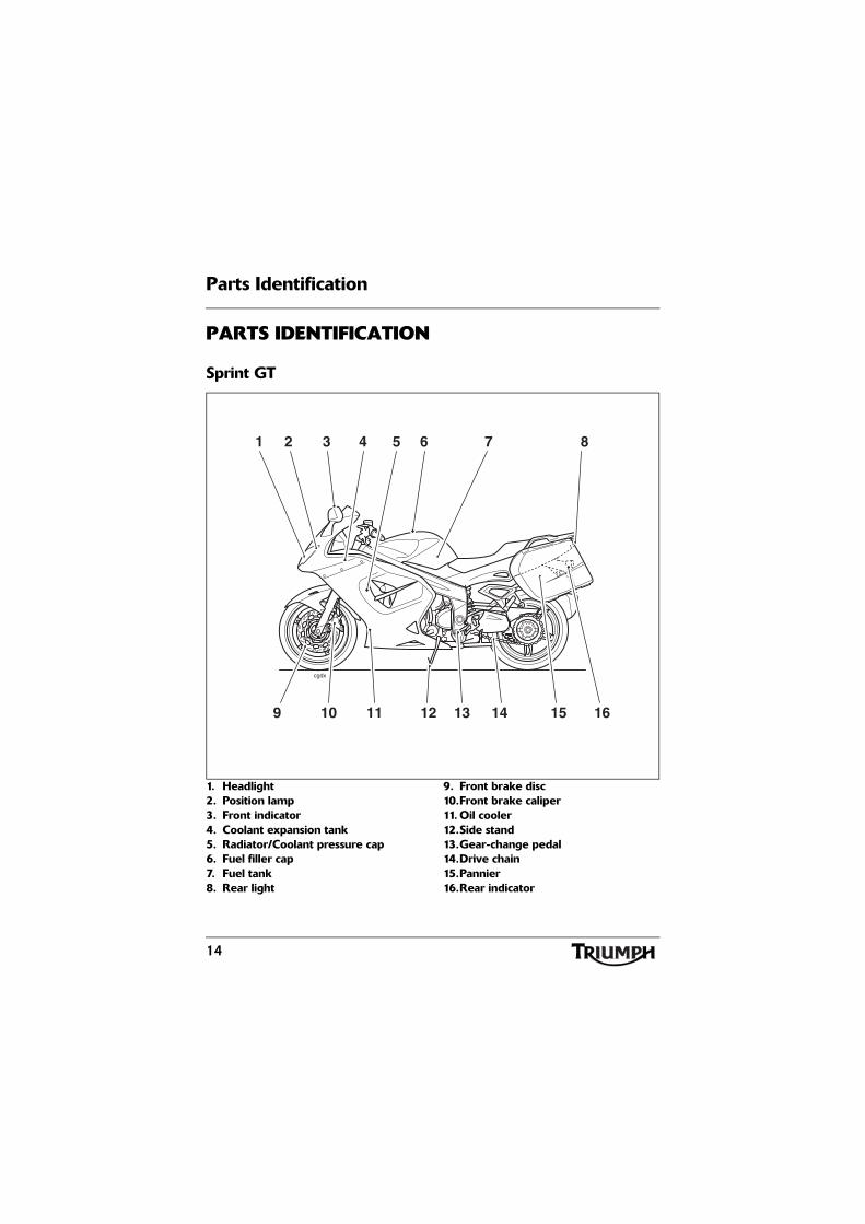
Sprint GT
1. Headlight2. Position lamp3. Front indicator4. Coolant expansion tank5. Radiator/Coolant pressure cap6. Fuel filler cap7. Fuel tank8. Rear light
9. Front brake disc10.Front brake caliper11. Oil cooler12.Side stand13.Gear-change pedal14.Drive chain15.Pannier16.Rear indicator
cgdx
51 6
15
3 74 8
141312 169 10 11
2
15
Parts Identification
PARTS IDENTIFICATION
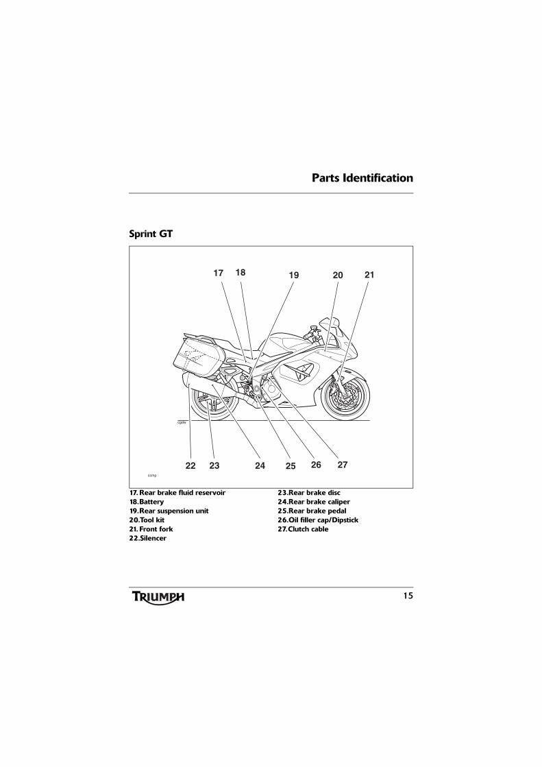
Sprint GT
17. Rear brake fluid reservoir18.Battery19.Rear suspension unit20.Tool kit21. Front fork22.Silencer
23.Rear brake disc24.Rear brake caliper25.Rear brake pedal26.Oil filler cap/Dipstick27.Clutch cable
cgdw
20
2523
19 21
272624
17
ccmp
18
22
16
Parts Identification
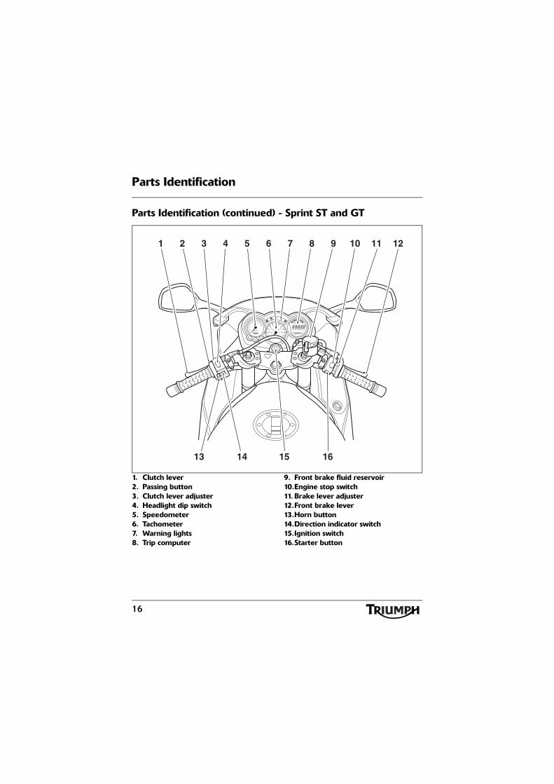
Parts Identification (continued) - Sprint ST and GT
1. Clutch lever2. Passing button3. Clutch lever adjuster4. Headlight dip switch5. Speedometer6. Tachometer7. Warning lights8. Trip computer
9. Front brake fluid reservoir10.Engine stop switch11. Brake lever adjuster12.Front brake lever13.Horn button14.Direction indicator switch15.Ignition switch16.Starter button
53 42 6 7 8 9 10 1211
15 1613 14
1
17
Serial Numbers
SERIAL NUMBERS
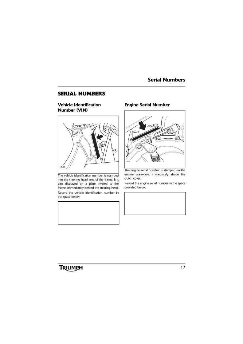
Vehicle Identification Number (VIN)
The vehicle identification number is stampedinto the steering head area of the frame. It isalso displayed on a plate, riveted to theframe, immediately behind the steering head.
Record the vehicle identification number inthe space below.
Engine Serial Number
The engine serial number is stamped on theengine crankcase, immediately above theclutch cover.
Record the engine serial number in the spaceprovided below.
ccmy

Serial Numbers
18
This page intentionally left blank
General Information
19
GENERAL INFORMATION
Table of ContentsInstrument Panel Layout. . . . . . . . . . . . . . . . . . . . . . . . . . . . . . . . . . . . . . . . . . . . . . . . . . . . . . . 21
Speedometer . . . . . . . . . . . . . . . . . . . . . . . . . . . . . . . . . . . . . . . . . . . . . . . . . . . . . . . . . . . . . . . 22
Tachometer . . . . . . . . . . . . . . . . . . . . . . . . . . . . . . . . . . . . . . . . . . . . . . . . . . . . . . . . . . . . . . . . . 22
Odometer/Trip Meter. . . . . . . . . . . . . . . . . . . . . . . . . . . . . . . . . . . . . . . . . . . . . . . . . . . . . . . . . 22
Clock/Trip Computer . . . . . . . . . . . . . . . . . . . . . . . . . . . . . . . . . . . . . . . . . . . . . . . . . . . . . . . . . 23
Instantaneous Fuel Consumption . . . . . . . . . . . . . . . . . . . . . . . . . . . . . . . . . . . . . . . . . . . . 23Average Fuel Consumption . . . . . . . . . . . . . . . . . . . . . . . . . . . . . . . . . . . . . . . . . . . . . . . . 23Range. . . . . . . . . . . . . . . . . . . . . . . . . . . . . . . . . . . . . . . . . . . . . . . . . . . . . . . . . . . . . . . . . . 23Journey Distance . . . . . . . . . . . . . . . . . . . . . . . . . . . . . . . . . . . . . . . . . . . . . . . . . . . . . . . . . 23Journey Time . . . . . . . . . . . . . . . . . . . . . . . . . . . . . . . . . . . . . . . . . . . . . . . . . . . . . . . . . . . . 23Average Speed . . . . . . . . . . . . . . . . . . . . . . . . . . . . . . . . . . . . . . . . . . . . . . . . . . . . . . . . . . 23Maximum Speed . . . . . . . . . . . . . . . . . . . . . . . . . . . . . . . . . . . . . . . . . . . . . . . . . . . . . . . . 23Trip Computer Operation . . . . . . . . . . . . . . . . . . . . . . . . . . . . . . . . . . . . . . . . . . . . . . . . . . 23Trip Computer Reset . . . . . . . . . . . . . . . . . . . . . . . . . . . . . . . . . . . . . . . . . . . . . . . . . . . . . . 24Clock Adjustment . . . . . . . . . . . . . . . . . . . . . . . . . . . . . . . . . . . . . . . . . . . . . . . . . . . . . . . . 24
Coolant Temperature Gauge . . . . . . . . . . . . . . . . . . . . . . . . . . . . . . . . . . . . . . . . . . . . . . . . . . . 25
Fuel Gauge . . . . . . . . . . . . . . . . . . . . . . . . . . . . . . . . . . . . . . . . . . . . . . . . . . . . . . . . . . . . . . . . . 26
Warning Lights . . . . . . . . . . . . . . . . . . . . . . . . . . . . . . . . . . . . . . . . . . . . . . . . . . . . . . . . . . . . . . 27
Direction Indicators . . . . . . . . . . . . . . . . . . . . . . . . . . . . . . . . . . . . . . . . . . . . . . . . . . . . . . . 27High Beam. . . . . . . . . . . . . . . . . . . . . . . . . . . . . . . . . . . . . . . . . . . . . . . . . . . . . . . . . . . . . . 27Low Fuel. . . . . . . . . . . . . . . . . . . . . . . . . . . . . . . . . . . . . . . . . . . . . . . . . . . . . . . . . . . . . . . . 27Neutral . . . . . . . . . . . . . . . . . . . . . . . . . . . . . . . . . . . . . . . . . . . . . . . . . . . . . . . . . . . . . . . . . 27Low Oil Pressure Warning Light . . . . . . . . . . . . . . . . . . . . . . . . . . . . . . . . . . . . . . . . . . . . . 27High Coolant Temperature Warning Light. . . . . . . . . . . . . . . . . . . . . . . . . . . . . . . . . . . . . 27Engine Management System Malfunction Indicator Light . . . . . . . . . . . . . . . . . . . . . . . . 28Alarm Indicator Light. . . . . . . . . . . . . . . . . . . . . . . . . . . . . . . . . . . . . . . . . . . . . . . . . . . . . . 28ABS (Anti-Lock Brake System) Indicator Light - Sprint GT only . . . . . . . . . . . . . . . . . . . . 29
Ignition Key . . . . . . . . . . . . . . . . . . . . . . . . . . . . . . . . . . . . . . . . . . . . . . . . . . . . . . . . . . . . . . . . . 29
Ignition Switch/Steering Lock. . . . . . . . . . . . . . . . . . . . . . . . . . . . . . . . . . . . . . . . . . . . . . . . . . . 30
Ignition Switch Positions . . . . . . . . . . . . . . . . . . . . . . . . . . . . . . . . . . . . . . . . . . . . . . . . . . . 30
General Information
20
Brake and Clutch Lever Adjusters . . . . . . . . . . . . . . . . . . . . . . . . . . . . . . . . . . . . . . . . . . . . . . . 31
Right Handlebar Switches . . . . . . . . . . . . . . . . . . . . . . . . . . . . . . . . . . . . . . . . . . . . . . . . . . . . . 32
Engine Stop Switch . . . . . . . . . . . . . . . . . . . . . . . . . . . . . . . . . . . . . . . . . . . . . . . . . . . . . . . 32Starter Button . . . . . . . . . . . . . . . . . . . . . . . . . . . . . . . . . . . . . . . . . . . . . . . . . . . . . . . . . . . 33
Left Handlebar Switches. . . . . . . . . . . . . . . . . . . . . . . . . . . . . . . . . . . . . . . . . . . . . . . . . . . . . . . 33
Headlight Dip Switch. . . . . . . . . . . . . . . . . . . . . . . . . . . . . . . . . . . . . . . . . . . . . . . . . . . . . . 33Direction Indicator Switch . . . . . . . . . . . . . . . . . . . . . . . . . . . . . . . . . . . . . . . . . . . . . . . . . . 34Horn Button. . . . . . . . . . . . . . . . . . . . . . . . . . . . . . . . . . . . . . . . . . . . . . . . . . . . . . . . . . . . . 34Pass Button . . . . . . . . . . . . . . . . . . . . . . . . . . . . . . . . . . . . . . . . . . . . . . . . . . . . . . . . . . . . . 34
Fuel Requirement/Refuelling . . . . . . . . . . . . . . . . . . . . . . . . . . . . . . . . . . . . . . . . . . . . . . . . . . . 34
Fuel Grade . . . . . . . . . . . . . . . . . . . . . . . . . . . . . . . . . . . . . . . . . . . . . . . . . . . . . . . . . . . . . . 34Fuel Tank Cap . . . . . . . . . . . . . . . . . . . . . . . . . . . . . . . . . . . . . . . . . . . . . . . . . . . . . . . . . . . 35Filling the Fuel Tank. . . . . . . . . . . . . . . . . . . . . . . . . . . . . . . . . . . . . . . . . . . . . . . . . . . . . . . 36
Stands . . . . . . . . . . . . . . . . . . . . . . . . . . . . . . . . . . . . . . . . . . . . . . . . . . . . . . . . . . . . . . . . . . . . . 37
Side Stand . . . . . . . . . . . . . . . . . . . . . . . . . . . . . . . . . . . . . . . . . . . . . . . . . . . . . . . . . . . . . . 37Centre Stand . . . . . . . . . . . . . . . . . . . . . . . . . . . . . . . . . . . . . . . . . . . . . . . . . . . . . . . . . . . . 37Lifting Handle . . . . . . . . . . . . . . . . . . . . . . . . . . . . . . . . . . . . . . . . . . . . . . . . . . . . . . . . . . . 38
Tool Kit and Handbook . . . . . . . . . . . . . . . . . . . . . . . . . . . . . . . . . . . . . . . . . . . . . . . . . . . . . . . 38
Seat - Sprint ST . . . . . . . . . . . . . . . . . . . . . . . . . . . . . . . . . . . . . . . . . . . . . . . . . . . . . . . . . . . . . . 39
Seat - Sprint GT . . . . . . . . . . . . . . . . . . . . . . . . . . . . . . . . . . . . . . . . . . . . . . . . . . . . . . . . . . . . . 39
Seat Care . . . . . . . . . . . . . . . . . . . . . . . . . . . . . . . . . . . . . . . . . . . . . . . . . . . . . . . . . . . . . . . 40
Helmet Hooks - Sprint GT . . . . . . . . . . . . . . . . . . . . . . . . . . . . . . . . . . . . . . . . . . . . . . . . . . . . . 40
Triumph Accessory D-lock Storage - Sprint GT models only . . . . . . . . . . . . . . . . . . . . . . . . . . 41
Pannier System - Sprint GT . . . . . . . . . . . . . . . . . . . . . . . . . . . . . . . . . . . . . . . . . . . . . . . . . . . . 41
Pannier Operation . . . . . . . . . . . . . . . . . . . . . . . . . . . . . . . . . . . . . . . . . . . . . . . . . . . . . . . . 43
Electrical Accessory Socket . . . . . . . . . . . . . . . . . . . . . . . . . . . . . . . . . . . . . . . . . . . . . . . . . . . . . 46
Running-In . . . . . . . . . . . . . . . . . . . . . . . . . . . . . . . . . . . . . . . . . . . . . . . . . . . . . . . . . . . . . . . . . 46
Safe Operation . . . . . . . . . . . . . . . . . . . . . . . . . . . . . . . . . . . . . . . . . . . . . . . . . . . . . . . . . . . . . . 47
Daily Safety Checks . . . . . . . . . . . . . . . . . . . . . . . . . . . . . . . . . . . . . . . . . . . . . . . . . . . . . . . 47
21
General Information
Instrument Panel Layout
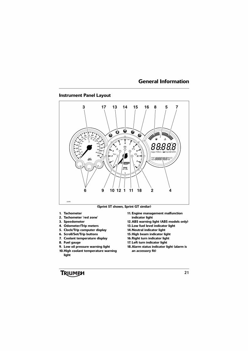
(Sprint ST shown, Sprint GT similar)
1. Tachometer2. Tachometer 'red zone'3. Speedometer4. Odometer/Trip meters5. Clock/Trip computer display6. Scroll/Set/Trip buttons7. Coolant temperature display8. Fuel gauge9. Low oil pressure warning light10.High coolant temperature warning
light
11. Engine management malfunction indicator light
12.ABS warning light (ABS models only)13.Low fuel level indicator light14.Neutral indicator light15.High beam indicator light16.Right turn indicator light17. Left turn indicator light18.Alarm status indicator light (alarm is
an accessory fit)
ccmk
km/h
17 15 1613 14 8 75
10 12 18111 2 46 9
3
22
General Information
SpeedometerThe speedometer indicates the road speed ofthe motorcycle.
TachometerThe tachometer shows the engine speed inrevolutions per minute - rpm (r/min). On theright side of the tachometer face is the'red zone'. Engine rpm (r/min) in the redzone is above maximum recommendedengine speed and is also above the range forbest performance.
Odometer/Trip Meter
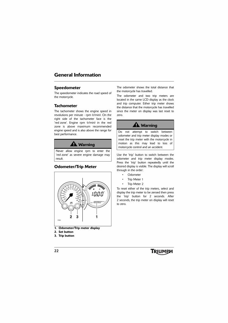
1. Odometer/Trip meter display2. Set button3. Trip button
The odometer shows the total distance thatthe motorcycle has travelled.
The odometer and two trip meters arelocated in the same LCD display as the clockand trip computer. Either trip meter showsthe distance that the motorcycle has travelledsince the meter on display was last reset tozero.
Use the 'trip' button to switch between theodometer and trip meter display modes.Press the 'trip' button repeatedly until thedesired display is visible. The display will scrollthrough in the order:
• Odometer
• Trip Meter 1
• Trip Meter 2
To reset either of the trip meters, select anddisplay the trip meter to be zeroed then pressthe 'trip' button for 2 seconds. After2 seconds, the trip meter on display will resetto zero.
WarningNever allow engine rpm to enter the'red zone' as severe engine damage mayresult.
km/h
12 3ccqu
WarningDo not attempt to switch betweenodometer and trip meter display modes orreset the trip meter with the motorcycle inmotion as this may lead to loss ofmotorcycle control and an accident.
23
General Information
Clock/Trip Computer
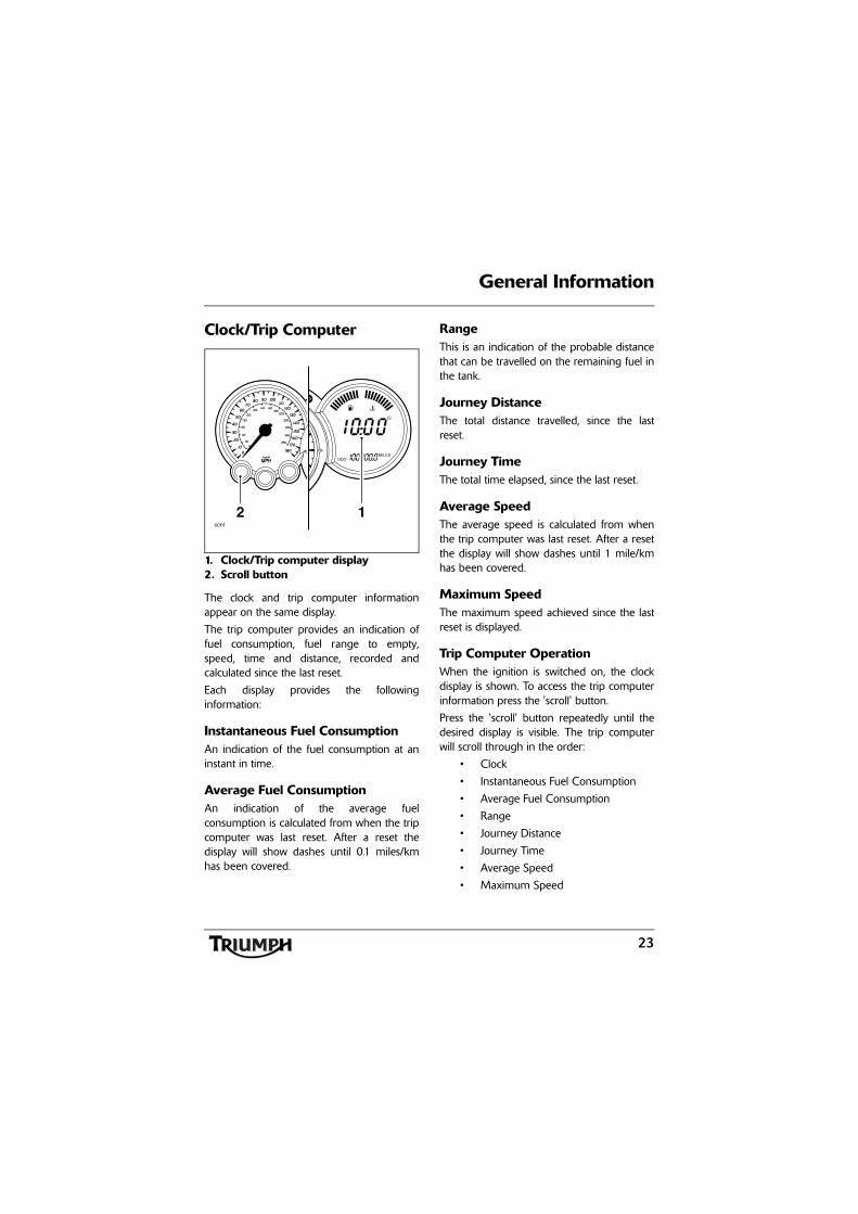
1. Clock/Trip computer display2. Scroll button
The clock and trip computer informationappear on the same display.
The trip computer provides an indication offuel consumption, fuel range to empty,speed, time and distance, recorded andcalculated since the last reset.
Each display provides the followinginformation:
Instantaneous Fuel ConsumptionAn indication of the fuel consumption at aninstant in time.
Average Fuel ConsumptionAn indication of the average fuelconsumption is calculated from when the tripcomputer was last reset. After a reset thedisplay will show dashes until 0.1 miles/kmhas been covered.
RangeThis is an indication of the probable distancethat can be travelled on the remaining fuel inthe tank.
Journey DistanceThe total distance travelled, since the lastreset.
Journey TimeThe total time elapsed, since the last reset.
Average SpeedThe average speed is calculated from whenthe trip computer was last reset. After a resetthe display will show dashes until 1 mile/kmhas been covered.
Maximum SpeedThe maximum speed achieved since the lastreset is displayed.
Trip Computer OperationWhen the ignition is switched on, the clockdisplay is shown. To access the trip computerinformation press the 'scroll' button.
Press the 'scroll' button repeatedly until thedesired display is visible. The trip computerwill scroll through in the order:
• Clock
• Instantaneous Fuel Consumption
• Average Fuel Consumption
• Range
• Journey Distance
• Journey Time
• Average Speed
• Maximum Speed
km/h
12ccnl
24
General Information
Trip Computer Reset
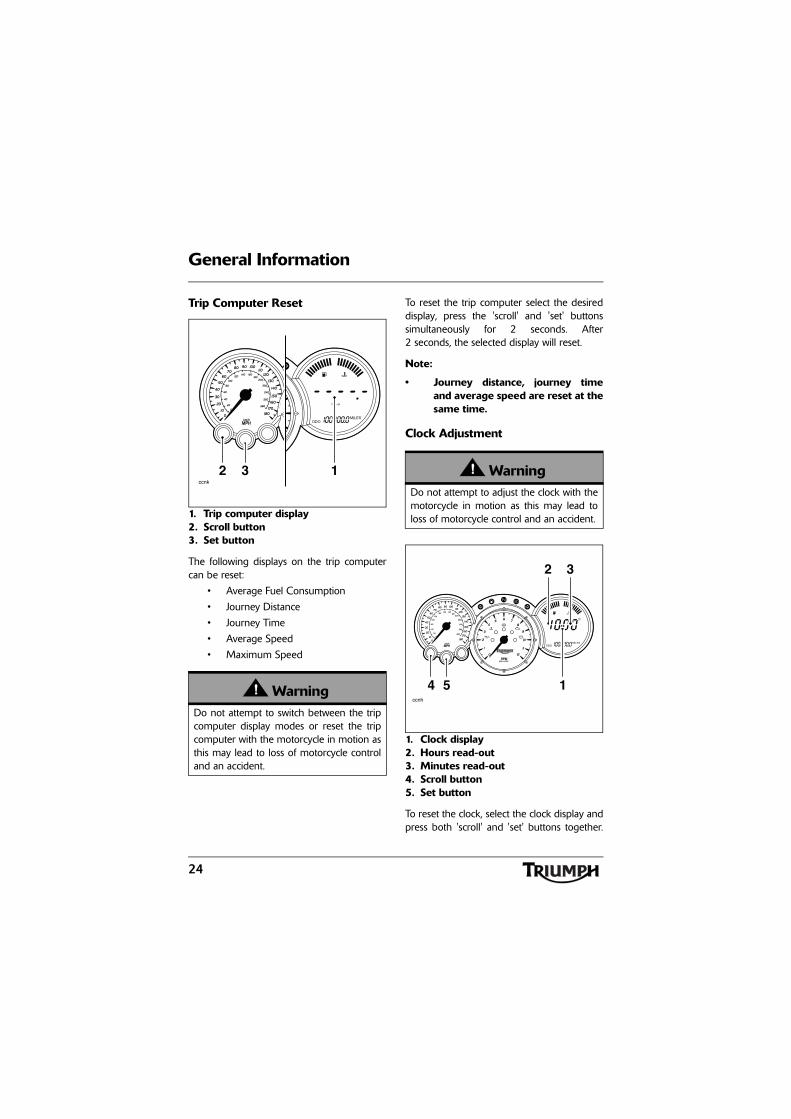
1. Trip computer display2. Scroll button3. Set button
The following displays on the trip computercan be reset:
• Average Fuel Consumption
• Journey Distance
• Journey Time
• Average Speed
• Maximum Speed
To reset the trip computer select the desireddisplay, press the 'scroll' and 'set' buttonssimultaneously for 2 seconds. After2 seconds, the selected display will reset.
Note:
• Journey distance, journey timeand average speed are reset at thesame time.
Clock Adjustment
1. Clock display2. Hours read-out3. Minutes read-out4. Scroll button5. Set button
To reset the clock, select the clock display andpress both 'scroll' and 'set' buttons together.
WarningDo not attempt to switch between the tripcomputer display modes or reset the tripcomputer with the motorcycle in motion asthis may lead to loss of motorcycle controland an accident.
ccnk
km/h
132 WarningDo not attempt to adjust the clock with themotorcycle in motion as this may lead toloss of motorcycle control and an accident.
ccnh
km/h
2 3
5 14
25
General Information
After a short time, the clock's hour display willstart to flash.
To reset the hour display, ensure that thehour display is still flashing then depress the'scroll' button to change the setting. Eachindividual press will change the setting byone digit. If the button is held, the display willcontinuously scroll through in single digitincrements.
When the correct hour display is shown,press the 'set' button. The minutes display willbegin to flash. The minutes display isadjusted in the same way as for the hours.
Once both hours and minutes are correctlyset, press the 'set' button to confirm thesetting. The display will cease to flash.
Coolant Temperature Gauge
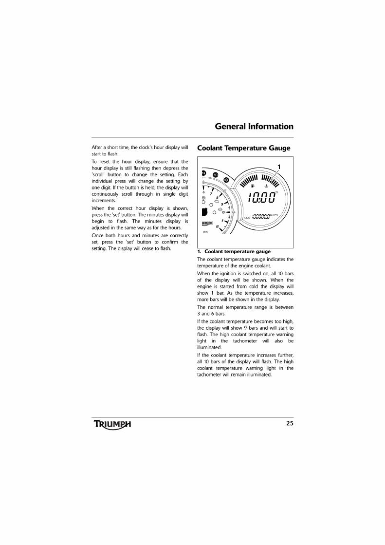
1. Coolant temperature gaugeThe coolant temperature gauge indicates thetemperature of the engine coolant.
When the ignition is switched on, all 10 barsof the display will be shown. When theengine is started from cold the display willshow 1 bar. As the temperature increases,more bars will be shown in the display.
The normal temperature range is between3 and 6 bars.
If the coolant temperature becomes too high,the display will show 9 bars and will start toflash. The high coolant temperature warninglight in the tachometer will also beilluminated.
If the coolant temperature increases further,all 10 bars of the display will flash. The highcoolant temperature warning light in thetachometer will remain illuminated.
ccnj
1
26
General Information
Fuel Gauge
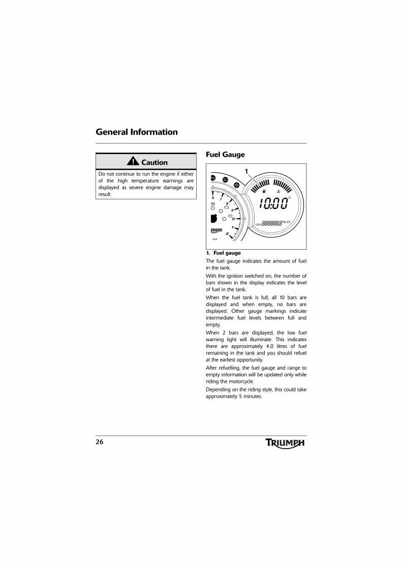
1. Fuel gaugeThe fuel gauge indicates the amount of fuelin the tank.
With the ignition switched on, the number ofbars shown in the display indicates the levelof fuel in the tank.
When the fuel tank is full, all 10 bars aredisplayed and when empty, no bars aredisplayed. Other gauge markings indicateintermediate fuel levels between full andempty.
When 2 bars are displayed, the low fuelwarning light will illuminate. This indicatesthere are approximately 4.0 litres of fuelremaining in the tank and you should refuelat the earliest opportunity.
After refuelling, the fuel gauge and range toempty information will be updated only whileriding the motorcycle.
Depending on the riding style, this could takeapproximately 5 minutes.
CautionDo not continue to run the engine if eitherof the high temperature warnings aredisplayed as severe engine damage mayresult.
ccni
1
27
General Information
Warning Lights
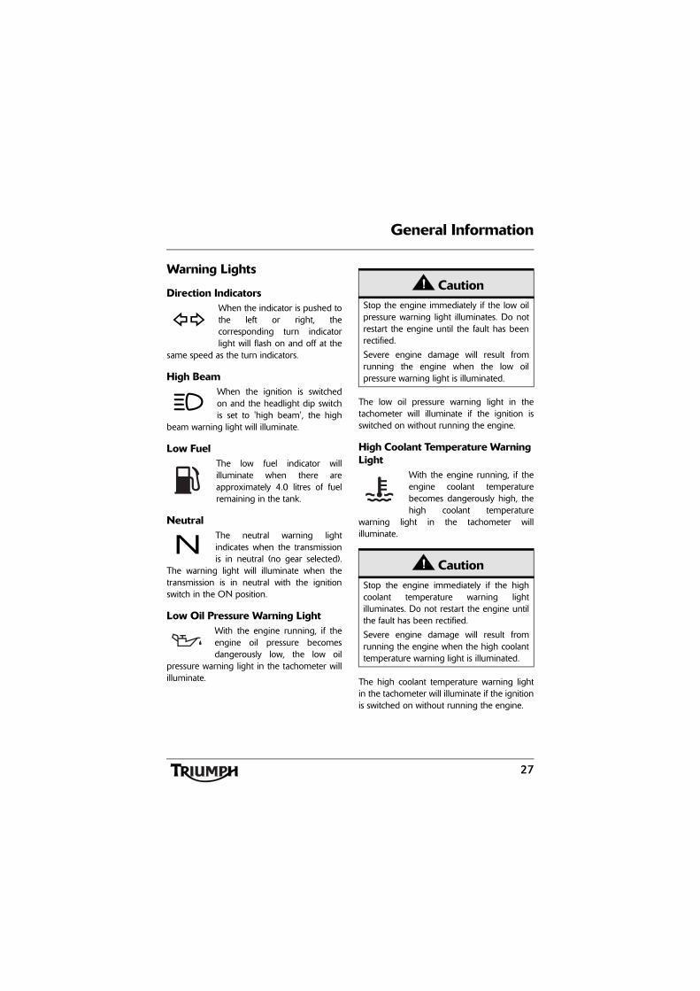
Direction IndicatorsWhen the indicator is pushed tothe left or right, thecorresponding turn indicatorlight will flash on and off at the
same speed as the turn indicators.
High BeamWhen the ignition is switchedon and the headlight dip switchis set to 'high beam', the high
beam warning light will illuminate.
Low FuelThe low fuel indicator willilluminate when there areapproximately 4.0 litres of fuelremaining in the tank.
NeutralThe neutral warning lightindicates when the transmissionis in neutral (no gear selected).
The warning light will illuminate when thetransmission is in neutral with the ignitionswitch in the ON position.
Low Oil Pressure Warning LightWith the engine running, if theengine oil pressure becomesdangerously low, the low oil
pressure warning light in the tachometer willilluminate.
The low oil pressure warning light in thetachometer will illuminate if the ignition isswitched on without running the engine.
High Coolant Temperature Warning Light
With the engine running, if theengine coolant temperaturebecomes dangerously high, thehigh coolant temperature
warning light in the tachometer willilluminate.
The high coolant temperature warning lightin the tachometer will illuminate if the ignitionis switched on without running the engine.
CautionStop the engine immediately if the low oilpressure warning light illuminates. Do notrestart the engine until the fault has beenrectified.
Severe engine damage will result fromrunning the engine when the low oilpressure warning light is illuminated.
CautionStop the engine immediately if the highcoolant temperature warning lightilluminates. Do not restart the engine untilthe fault has been rectified.
Severe engine damage will result fromrunning the engine when the high coolanttemperature warning light is illuminated.
28
General Information
Engine Management System Malfunction Indicator Light
The malfunction indicator lightfor the engine managementsystem illuminates when the
ignition is switched on (to indicate that it isworking) but should not become illuminatedwhen the engine is running.
If the malfunction indicator light becomesilluminated when the engine is running, thisindicates that a fault has occurred in one ormore of the systems controlled by the enginemanagement system. In such circumstances,the engine management system will switch to'limp-home' mode so that the journey maybe completed, if the fault is not so severe thatthe engine will not run.
Note:
• If the malfunction indicator lightflashes when the ignition isswitched on, contact an authorisedTriumph dealer as soon as possibleto have the situation rectified. Inthese circumstances the enginewill not start.
Alarm Indicator LightThe alarm light will illuminatewhen the conditions describedin the accessory alarm
instructions are met.
The light does not function unless an alarm isfitted.
WarningReduce speed and do not continue to ridefor longer than is necessary with themalfunction indicator light illuminated. Thefault may adversely affect engineperformance, exhaust emissions and fuelconsumption. Reduced engineperformance could cause a dangerousriding condition, leading to loss of controland an accident. Contact an authorisedTriumph dealer as soon as possible to havethe fault checked and rectified.
29
General Information
ABS (Anti-Lock Brake System) Indicator Light - Sprint GT only
The ABS indicator lightilluminates to show that the ABSfunction is not available.
Illumination is normal after engine start-up,and until the motorcycle first reaches a speedexceeding 6 mph (10 km/h). Unless there is afault, it should not illuminate again until theengine is restarted.
If the indicator light becomes illuminated atany other time while riding it indicates thatthe ABS has a malfunction that requiresinvestigation.
See also Braking on page 53.
Ignition Key
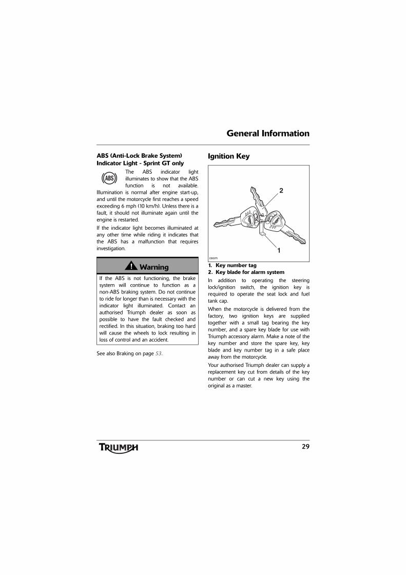
1. Key number tag2. Key blade for alarm systemIn addition to operating the steeringlock/ignition switch, the ignition key isrequired to operate the seat lock and fueltank cap.
When the motorcycle is delivered from thefactory, two ignition keys are suppliedtogether with a small tag bearing the keynumber, and a spare key blade for use withTriumph accessory alarm. Make a note of thekey number and store the spare key, keyblade and key number tag in a safe placeaway from the motorcycle.
Your authorised Triumph dealer can supply areplacement key cut from details of the keynumber or can cut a new key using theoriginal as a master.
WarningIf the ABS is not functioning, the brakesystem will continue to function as anon-ABS braking system. Do not continueto ride for longer than is necessary with theindicator light illuminated. Contact anauthorised Triumph dealer as soon aspossible to have the fault checked andrectified. In this situation, braking too hardwill cause the wheels to lock resulting inloss of control and an accident.
ceom
1
2
30
General Information
Note:
• On Sprint ST models, three unusedlocks are supplied with themotorcycle. These are for use withthe optional accessory panniersand top box and will ensure that,when fitted, the same key willoperate all the locks on themotorcycle.
• On Sprint GT models, one unusedlock is supplied with themotorcycle. This is for use with theoptional accessory top box and willensure that, when fitted, the samekey will operate all the locks onthe motorcycle.
Ignition Switch/Steering Lock
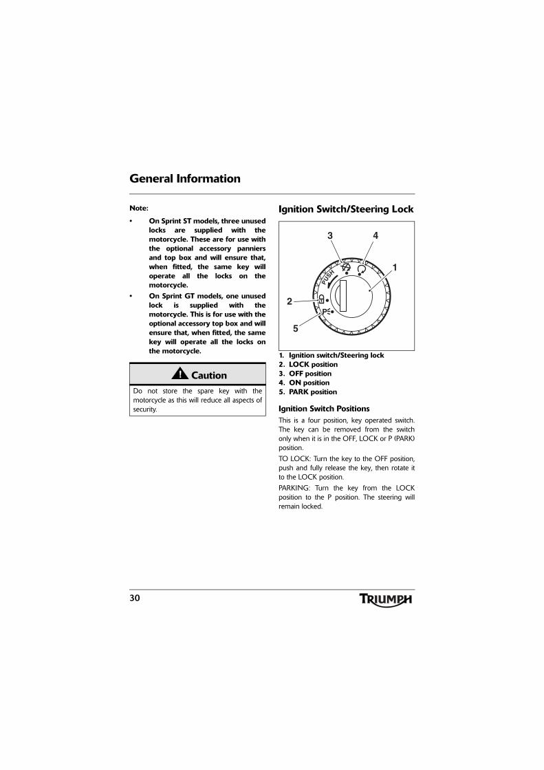
1. Ignition switch/Steering lock2. LOCK position3. OFF position4. ON position5. PARK position
Ignition Switch PositionsThis is a four position, key operated switch.The key can be removed from the switchonly when it is in the OFF, LOCK or P (PARK)position.
TO LOCK: Turn the key to the OFF position,push and fully release the key, then rotate itto the LOCK position.
PARKING: Turn the key from the LOCKposition to the P position. The steering willremain locked.
CautionDo not store the spare key with themotorcycle as this will reduce all aspects ofsecurity.
PU
SH
P
1
3 4
2
5
31
General Information
Note:
• Do not leave the steering lock inthe P position for long periods oftime as this will cause the batteryto discharge.
Brake and Clutch Lever Adjusters
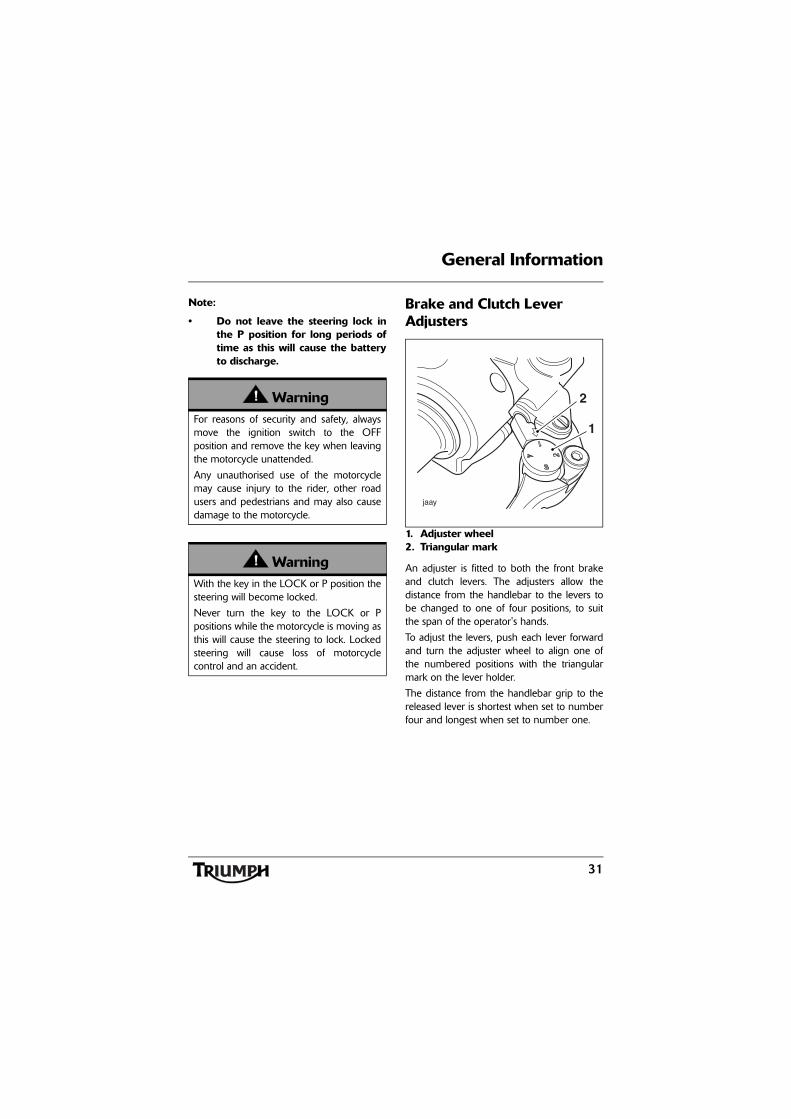
1. Adjuster wheel2. Triangular mark
An adjuster is fitted to both the front brakeand clutch levers. The adjusters allow thedistance from the handlebar to the levers tobe changed to one of four positions, to suitthe span of the operator's hands.
To adjust the levers, push each lever forwardand turn the adjuster wheel to align one ofthe numbered positions with the triangularmark on the lever holder.
The distance from the handlebar grip to thereleased lever is shortest when set to numberfour and longest when set to number one.
WarningFor reasons of security and safety, alwaysmove the ignition switch to the OFFposition and remove the key when leavingthe motorcycle unattended.
Any unauthorised use of the motorcyclemay cause injury to the rider, other roadusers and pedestrians and may also causedamage to the motorcycle.
WarningWith the key in the LOCK or P position thesteering will become locked.
Never turn the key to the LOCK or Ppositions while the motorcycle is moving asthis will cause the steering to lock. Lockedsteering will cause loss of motorcyclecontrol and an accident.
32
General Information
Right Handlebar Switches
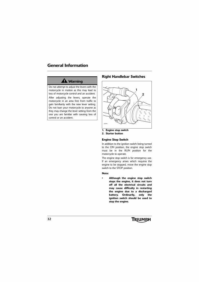
1. Engine stop switch2. Starter button
Engine Stop SwitchIn addition to the ignition switch being turnedto the ON position, the engine stop switchmust be in the RUN position for themotorcycle to operate.
The engine stop switch is for emergency use.If an emergency arises which requires theengine to be stopped, move the engine stopswitch to the STOP position.
Note:
• Although the engine stop switchstops the engine, it does not turnoff all the electrical circuits andmay cause difficulty in restartingthe engine due to a dischargedbattery. Ordinarily, only theignition switch should be used tostop the engine.
WarningDo not attempt to adjust the levers with themotorcycle in motion as this may lead toloss of motorcycle control and an accident.
After adjusting the levers, operate themotorcycle in an area free from traffic togain familiarity with the new lever setting.Do not loan your motorcycle to anyone asthey may change the lever setting from theone you are familiar with causing loss ofcontrol or an accident.
ccmm
21
33
General Information
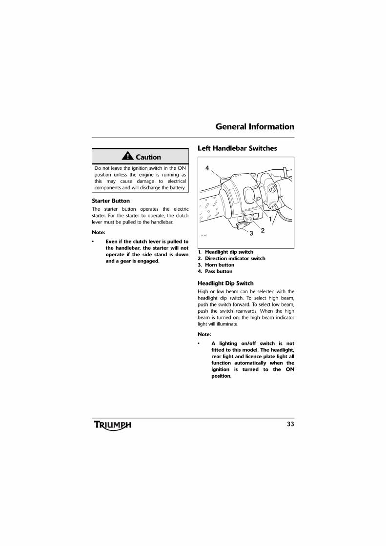
Starter ButtonThe starter button operates the electricstarter. For the starter to operate, the clutchlever must be pulled to the handlebar.
Note:
• Even if the clutch lever is pulled tothe handlebar, the starter will notoperate if the side stand is downand a gear is engaged.
Left Handlebar Switches
1. Headlight dip switch2. Direction indicator switch3. Horn button4. Pass button
Headlight Dip SwitchHigh or low beam can be selected with theheadlight dip switch. To select high beam,push the switch forward. To select low beam,push the switch rearwards. When the highbeam is turned on, the high beam indicatorlight will illuminate.
Note:
• A lighting on/off switch is notfitted to this model. The headlight,rear light and licence plate light allfunction automatically when theignition is turned to the ONposition.
CautionDo not leave the ignition switch in the ONposition unless the engine is running asthis may cause damage to electricalcomponents and will discharge the battery.
ccml
4
3 2
1
34
General Information
Direction Indicator SwitchWhen the indicator switch is pushed to theleft or right and released, the correspondingdirection indicators will flash on and off. Toturn off the indicators, push and release theswitch.
Horn ButtonWhen the horn button is pushed, with theignition switch turned to the ON position, thehorn will sound.
Pass ButtonWhen the pass button is pressed, theheadlight main beam will be switched on. Itwill remain on as long as the button is held inand will turn off as soon as the button isreleased.
Fuel Requirement/Refuelling
Fuel Grade
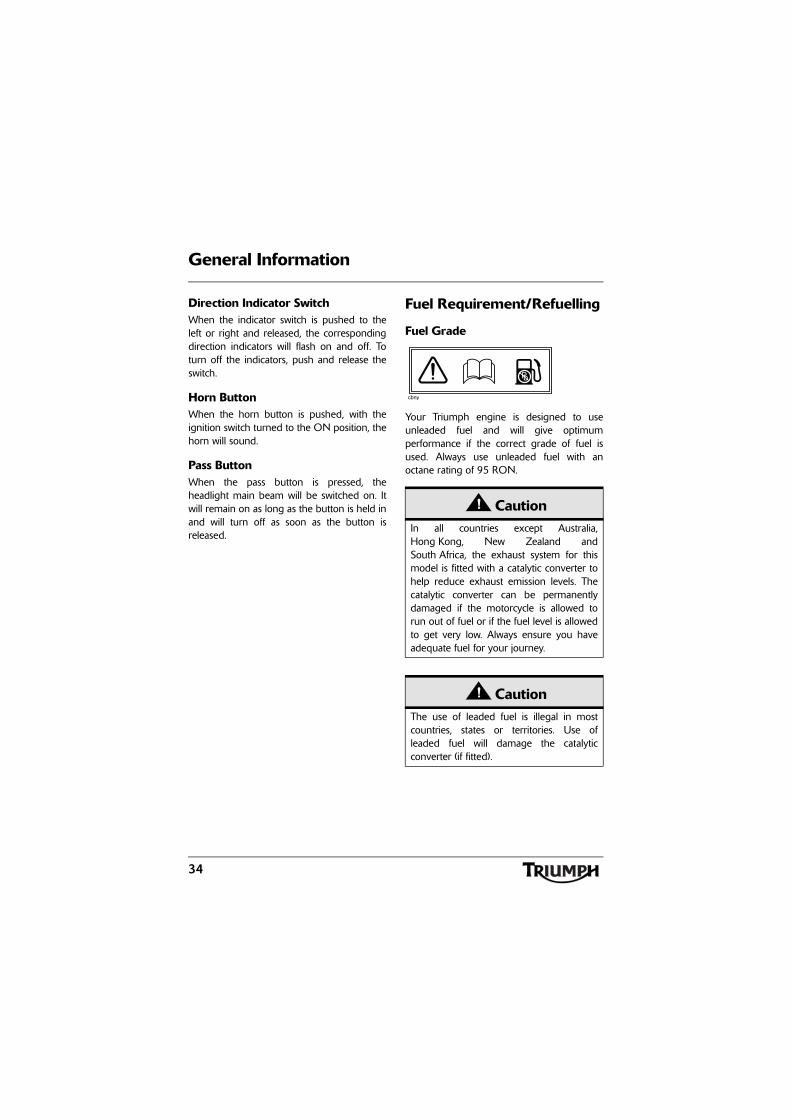
Your Triumph engine is designed to useunleaded fuel and will give optimumperformance if the correct grade of fuel isused. Always use unleaded fuel with anoctane rating of 95 RON.
CautionIn all countries except Australia,Hong Kong, New Zealand andSouth Africa, the exhaust system for thismodel is fitted with a catalytic converter tohelp reduce exhaust emission levels. Thecatalytic converter can be permanentlydamaged if the motorcycle is allowed torun out of fuel or if the fuel level is allowedto get very low. Always ensure you haveadequate fuel for your journey.
CautionThe use of leaded fuel is illegal in mostcountries, states or territories. Use ofleaded fuel will damage the catalyticconverter (if fitted).
Pb
cbny
35
General Information
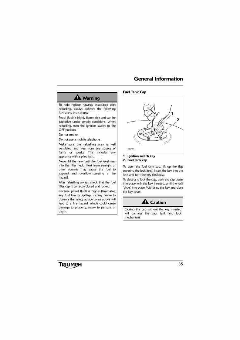
Fuel Tank Cap
1. Ignition switch key2. Fuel tank cap
To open the fuel tank cap, lift up the flapcovering the lock itself. Insert the key into thelock and turn the key clockwise.
To close and lock the cap, push the cap downinto place with the key inserted, until the lock'clicks' into place. Withdraw the key and closethe key cover.
WarningTo help reduce hazards associated withrefuelling, always observe the followingfuel safety instructions:
Petrol (fuel) is highly flammable and can beexplosive under certain conditions. Whenrefuelling, turn the ignition switch to theOFF position.
Do not smoke.
Do not use a mobile telephone.
Make sure the refuelling area is wellventilated and free from any source offlame or sparks. This includes anyappliance with a pilot light.
Never fill the tank until the fuel level risesinto the filler neck. Heat from sunlight orother sources may cause the fuel toexpand and overflow creating a firehazard.
After refuelling always check that the fuelfiller cap is correctly closed and locked.
Because petrol (fuel) is highly flammable,any fuel leak or spillage, or any failure toobserve the safety advice given above willlead to a fire hazard, which could causedamage to property, injury to persons ordeath.
CautionClosing the cap without the key insertedwill damage the cap, tank and lockmechanism.
1
2
cbmm
36
General Information
Filling the Fuel TankAvoid filling the tank in rainy or dustyconditions where airborne material cancontaminate the fuel.
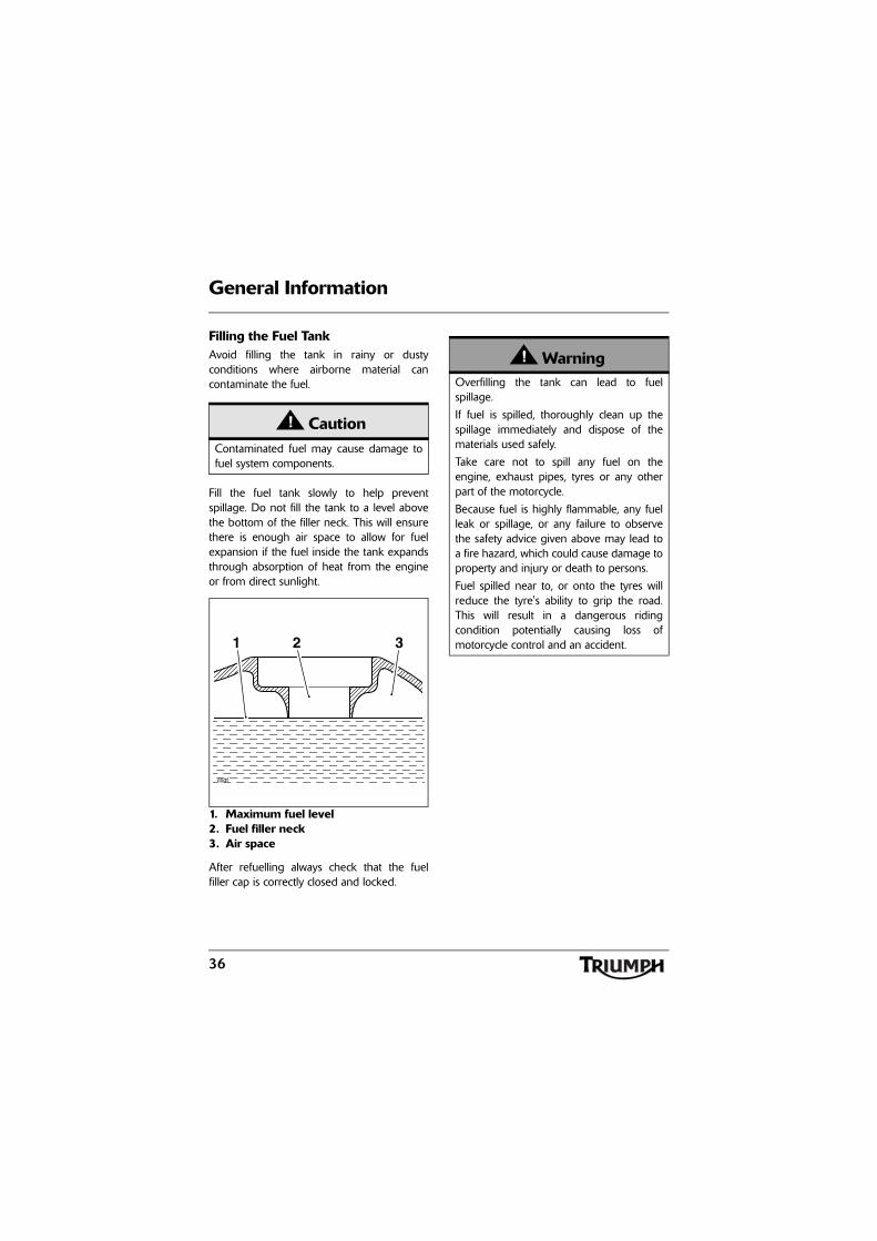
Fill the fuel tank slowly to help preventspillage. Do not fill the tank to a level abovethe bottom of the filler neck. This will ensurethere is enough air space to allow for fuelexpansion if the fuel inside the tank expandsthrough absorption of heat from the engineor from direct sunlight.
1. Maximum fuel level2. Fuel filler neck3. Air space
After refuelling always check that the fuelfiller cap is correctly closed and locked.
CautionContaminated fuel may cause damage tofuel system components.
1 2 3
cbdf
WarningOverfilling the tank can lead to fuelspillage.
If fuel is spilled, thoroughly clean up thespillage immediately and dispose of thematerials used safely.
Take care not to spill any fuel on theengine, exhaust pipes, tyres or any otherpart of the motorcycle.
Because fuel is highly flammable, any fuelleak or spillage, or any failure to observethe safety advice given above may lead toa fire hazard, which could cause damage toproperty and injury or death to persons.
Fuel spilled near to, or onto the tyres willreduce the tyre's ability to grip the road.This will result in a dangerous ridingcondition potentially causing loss ofmotorcycle control and an accident.
37
General Information
Stands
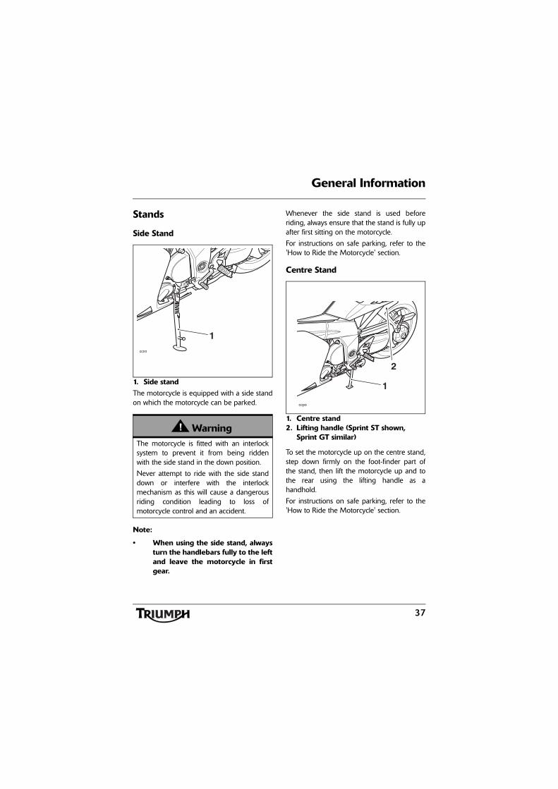
Side Stand
1. Side standThe motorcycle is equipped with a side standon which the motorcycle can be parked.
Note:
• When using the side stand, alwaysturn the handlebars fully to the leftand leave the motorcycle in firstgear.
Whenever the side stand is used beforeriding, always ensure that the stand is fully upafter first sitting on the motorcycle.
For instructions on safe parking, refer to the'How to Ride the Motorcycle' section.
Centre Stand
1. Centre stand2. Lifting handle (Sprint ST shown,
Sprint GT similar)
To set the motorcycle up on the centre stand,step down firmly on the foot-finder part ofthe stand, then lift the motorcycle up and tothe rear using the lifting handle as ahandhold.
For instructions on safe parking, refer to the'How to Ride the Motorcycle' section.
WarningThe motorcycle is fitted with an interlocksystem to prevent it from being riddenwith the side stand in the down position.
Never attempt to ride with the side standdown or interfere with the interlockmechanism as this will cause a dangerousriding condition leading to loss ofmotorcycle control and an accident.
1ccnn
1
2
ccpo
38
General Information
Lifting HandleThe lifting handle is located on the left handside of the motorcycle, and is the upper edgeof the pillion footrest hanger.
Always use the lifting handle or grab rail topark the motorcycle on the centre stand.
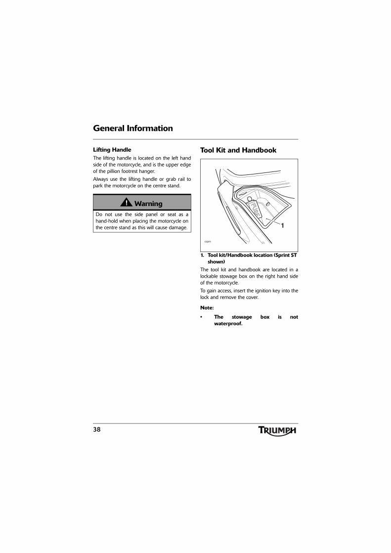
Tool Kit and Handbook
1. Tool kit/Handbook location (Sprint ST shown)
The tool kit and handbook are located in alockable stowage box on the right hand sideof the motorcycle.
To gain access, insert the ignition key into thelock and remove the cover.
Note:
• The stowage box is notwaterproof.
WarningDo not use the side panel or seat as ahand-hold when placing the motorcycle onthe centre stand as this will cause damage.
ccpm
1
39
General Information
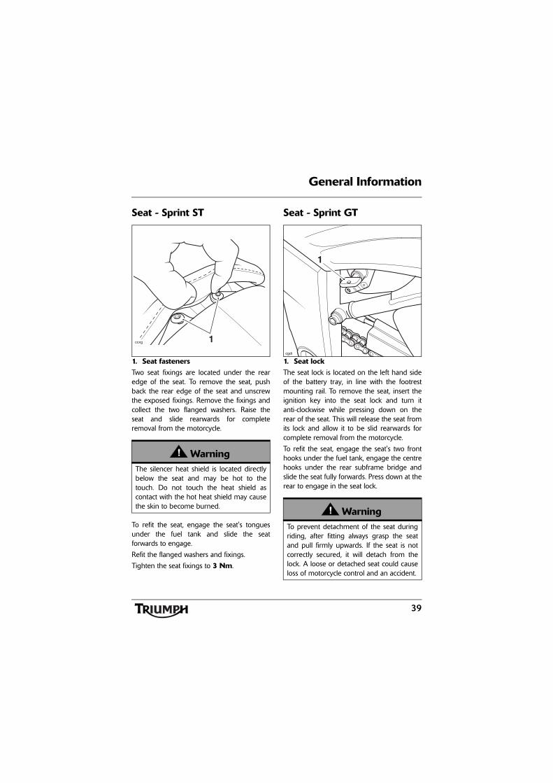
Seat - Sprint ST
1. Seat fastenersTwo seat fixings are located under the rearedge of the seat. To remove the seat, pushback the rear edge of the seat and unscrewthe exposed fixings. Remove the fixings andcollect the two flanged washers. Raise theseat and slide rearwards for completeremoval from the motorcycle.
To refit the seat, engage the seat's tonguesunder the fuel tank and slide the seatforwards to engage.
Refit the flanged washers and fixings.
Tighten the seat fixings to 3 Nm.
Seat - Sprint GT
1. Seat lockThe seat lock is located on the left hand sideof the battery tray, in line with the footrestmounting rail. To remove the seat, insert theignition key into the seat lock and turn itanti-clockwise while pressing down on therear of the seat. This will release the seat fromits lock and allow it to be slid rearwards forcomplete removal from the motorcycle.
To refit the seat, engage the seat's two fronthooks under the fuel tank, engage the centrehooks under the rear subframe bridge andslide the seat fully forwards. Press down at therear to engage in the seat lock.
WarningThe silencer heat shield is located directlybelow the seat and may be hot to thetouch. Do not touch the heat shield ascontact with the hot heat shield may causethe skin to become burned.
ccxg 1
WarningTo prevent detachment of the seat duringriding, after fitting always grasp the seatand pull firmly upwards. If the seat is notcorrectly secured, it will detach from thelock. A loose or detached seat could causeloss of motorcycle control and an accident.
cgdi
1
40
General Information
Seat CareTo prevent damage to the seat or seat cover,care must be taken not to drop or lean theseat against any surface which may damagethe seat or seat cover.
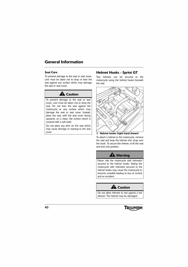
Helmet Hooks - Sprint GTTwo helmets can be secured to themotorcycle using the helmet hooks beneaththe seat.
1. Helmet hooks (right hand shown)To attach a helmet to the motorcycle, removethe seat and loop the helmet chin strap overthe hook. To secure the helmet, re-fit the seatand lock into position.
CautionTo prevent damage to the seat or seatcover, care must be taken not to drop theseat. Do not lean the seat against themotorcycle or any surface which maydamage the seat or seat cover. Instead,place the seat, with the seat cover facingupwards, on a clean, flat surface which iscovered with a soft cloth.
Do not place any item on the seat whichmay cause damage or staining to the seatcover.
WarningNever ride the motorcycle with helmet(s)secured to the helmet hooks. Riding themotorcycle with helmet(s) secured to thehelmet hooks may cause the motorcycle tobecome unstable leading to loss of controland an accident.
CautionDo not allow helmets to rest against a hotsilencer. The helmet may be damaged.
1
cgdr
41
General Information
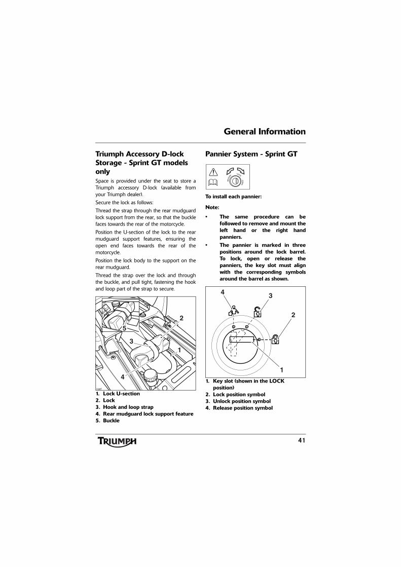
Triumph Accessory D-lock Storage - Sprint GT models onlySpace is provided under the seat to store aTriumph accessory D-lock (available fromyour Triumph dealer).
Secure the lock as follows:
Thread the strap through the rear mudguardlock support from the rear, so that the bucklefaces towards the rear of the motorcycle.
Position the U-section of the lock to the rearmudguard support features, ensuring theopen end faces towards the rear of themotorcycle.
Position the lock body to the support on therear mudguard.
Thread the strap over the lock and throughthe buckle, and pull tight, fastening the hookand loop part of the strap to secure.
1. Lock U-section2. Lock3. Hook and loop strap4. Rear mudguard lock support feature5. Buckle
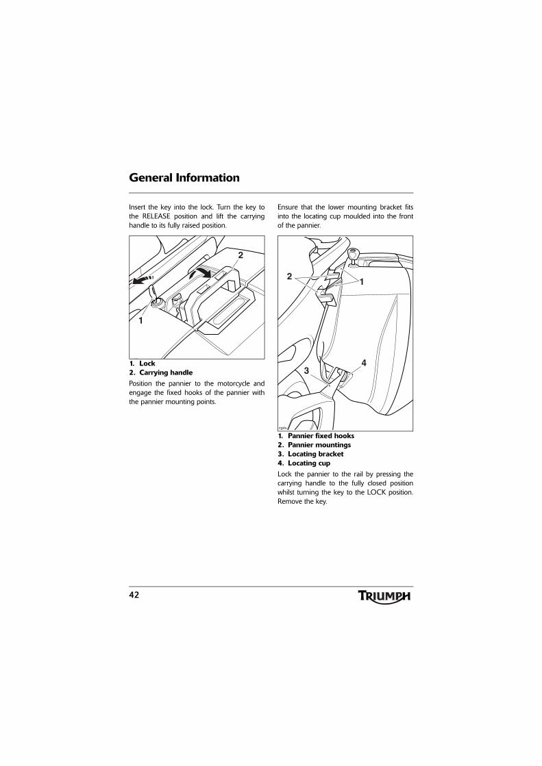
Pannier System - Sprint GT
To install each pannier:
Note:
• The same procedure can befollowed to remove and mount theleft hand or the right handpanniers.
• The pannier is marked in threepositions around the lock barrel.To lock, open or release thepanniers, the key slot must alignwith the corresponding symbolsaround the barrel as shown.
1. Key slot (shown in the LOCK position)
2. Lock position symbol3. Unlock position symbol4. Release position symbol
cgef
5
31
4
2
REL
EASE
••LOCK
•OPEN
2
34
1
42
General Information
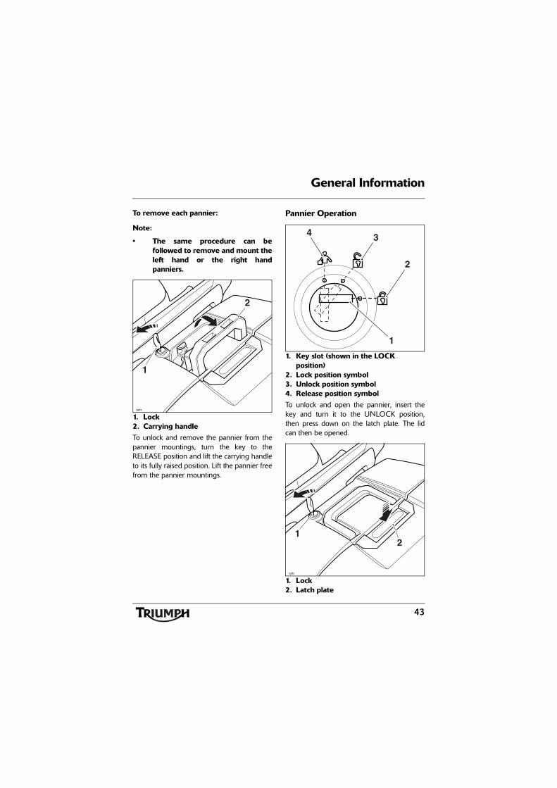
Insert the key into the lock. Turn the key tothe RELEASE position and lift the carryinghandle to its fully raised position.
1. Lock2. Carrying handlePosition the pannier to the motorcycle andengage the fixed hooks of the pannier withthe pannier mounting points.
Ensure that the lower mounting bracket fitsinto the locating cup moulded into the frontof the pannier.
1. Pannier fixed hooks2. Pannier mountings3. Locating bracket4. Locating cupLock the pannier to the rail by pressing thecarrying handle to the fully closed positionwhilst turning the key to the LOCK position.Remove the key.
1
cgds
2
cgdu
2 1
34
43
General Information
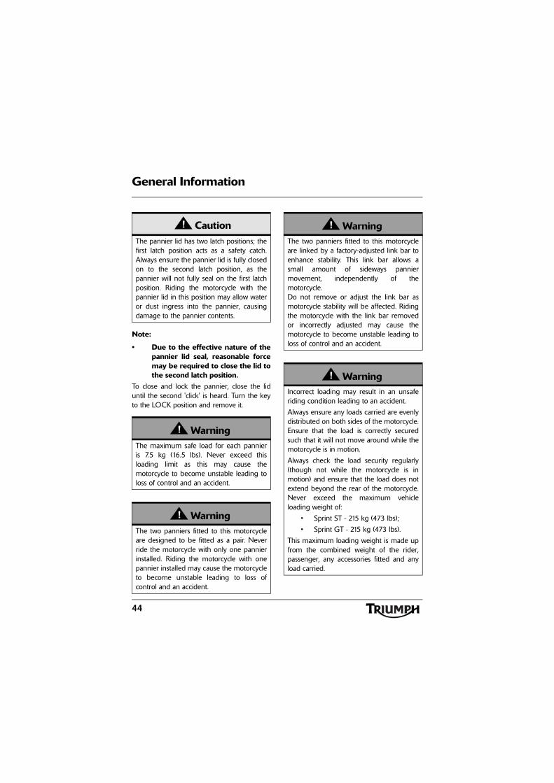
To remove each pannier:
Note:
• The same procedure can befollowed to remove and mount theleft hand or the right handpanniers.
1. Lock2. Carrying handleTo unlock and remove the pannier from thepannier mountings, turn the key to theRELEASE position and lift the carrying handleto its fully raised position. Lift the pannier freefrom the pannier mountings.
Pannier Operation
1. Key slot (shown in the LOCK position)
2. Lock position symbol3. Unlock position symbol4. Release position symbolTo unlock and open the pannier, insert thekey and turn it to the UNLOCK position,then press down on the latch plate. The lidcan then be opened.
1. Lock2. Latch plate
1
cgds
2
2
34
1
1
cgds
2
44
General Information
Note:
• Due to the effective nature of thepannier lid seal, reasonable forcemay be required to close the lid tothe second latch position.
To close and lock the pannier, close the liduntil the second 'click' is heard. Turn the keyto the LOCK position and remove it.
CautionThe pannier lid has two latch positions; thefirst latch position acts as a safety catch.Always ensure the pannier lid is fully closedon to the second latch position, as thepannier will not fully seal on the first latchposition. Riding the motorcycle with thepannier lid in this position may allow wateror dust ingress into the pannier, causingdamage to the pannier contents.
WarningThe maximum safe load for each pannieris 7.5 kg (16.5 lbs). Never exceed thisloading limit as this may cause themotorcycle to become unstable leading toloss of control and an accident.
WarningThe two panniers fitted to this motorcycleare designed to be fitted as a pair. Neverride the motorcycle with only one pannierinstalled. Riding the motorcycle with onepannier installed may cause the motorcycleto become unstable leading to loss ofcontrol and an accident.
WarningThe two panniers fitted to this motorcycleare linked by a factory-adjusted link bar toenhance stability. This link bar allows asmall amount of sideways panniermovement, independently of themotorcycle. Do not remove or adjust the link bar asmotorcycle stability will be affected. Ridingthe motorcycle with the link bar removedor incorrectly adjusted may cause themotorcycle to become unstable leading toloss of control and an accident.
WarningIncorrect loading may result in an unsaferiding condition leading to an accident.
Always ensure any loads carried are evenlydistributed on both sides of the motorcycle.Ensure that the load is correctly securedsuch that it will not move around while themotorcycle is in motion.
Always check the load security regularly(though not while the motorcycle is inmotion) and ensure that the load does notextend beyond the rear of the motorcycle.Never exceed the maximum vehicleloading weight of:
• Sprint ST - 215 kg (473 lbs);
• Sprint GT - 215 kg (473 lbs).
This maximum loading weight is made upfrom the combined weight of the rider,passenger, any accessories fitted and anyload carried.
45
General Information
WarningAfter fitting or removing the panniers,operate the motorcycle in a safe area freefrom traffic to gain familiarity with the newhandling characteristics. Operation whennot familiar with the new characteristics ofthe motorcycle may result in loss of controland an accident.
WarningNever ride an accessory equippedmotorcycle, or a motorcycle carrying apayload of any kind, at speeds above80 mph (130 km/h). In either/both ofthese conditions, speeds in excess of80 mph (130 km/h) should not beattempted even where the legal speedlimit permits this.
The presence of accessories and/orpayload will cause changes in the stabilityand handling of the motorcycle.
Failure to allow for changes in motorcyclestability may lead to loss of control or anaccident. Remember that the 80 mph(130 km/h) absolute limit will reduce bythe fitting of non-approved accessories,incorrect loading, worn tyres, overallmotorcycle condition and poor road orweather conditions.
WarningThis motorcycle must not be operatedabove the legal road speed limit except inauthorised closed-course conditions.
WarningOnly operate this Triumph motorcycle athigh speed in closed-course on-roadcompetition or on closed-course racetracks.High-speed operation should only beattempted by riders who have beeninstructed in the techniques necessary forhigh-speed riding and are familiar with themotorcycle's characteristics in allconditions.
High-speed operation in any othercircumstances is dangerous and will lead toloss of motorcycle control and an accident.
46
General Information
Electrical Accessory Socket
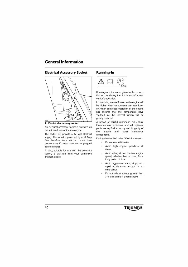
1. Electrical accessory socketAn electrical accessory socket is provided onthe left hand side of the motorcycle.
The socket will provide a 12 Volt electricalsupply. The socket is protected by a 10 Ampfuse therefore items with a current drawgreater than 10 amps must not be pluggedinto the socket.
A plug, suitable for use with the accessorysocket, is available from your authorisedTriumph dealer.
Running-In
Running-in is the name given to the processthat occurs during the first hours of a newvehicle's operation.
In particular, internal friction in the engine willbe higher when components are new. Lateron, when continued operation of the enginehas ensured that the components have'bedded in', this internal friction will begreatly reduced.
A period of careful running-in will ensurelower exhaust emissions, and will optimiseperformance, fuel economy and longevity ofthe engine and other motorcyclecomponents.
During the first 500 miles (800 kilometres):
• Do not use full throttle.
• Avoid high engine speeds at alltimes.
• Avoid riding at one constant enginespeed, whether fast or slow, for along period of time.
• Avoid aggressive starts, stops, andrapid accelerations, except in anemergency.
• Do not ride at speeds greater than3/4 of maximum engine speed.
cgdj
1
R.P.M.
47
General Information
From 500 to 1000 miles (800 to1500 kilometres):
• Engine speed can gradually beincreased to the rev limit for shortperiods.
Both during and after running-in has beencompleted:
• Do not over-rev the engine whencold.
• Do not let the engine labour. Alwaysdownshift before the engine beginsto 'struggle'.
• Do not ride with engine speedsunnecessarily high. Changing up agear helps reduce fuel consumption,reduces noise and helps to protectthe environment.
Safe Operation
Daily Safety Checks
Check the following items each day beforeyou ride. The time required is minimal, andthese checks will help ensure a safe, reliableride.
If any irregularities are found during thesechecks, refer to the Maintenance andAdjustment section or see your authorisedTriumph dealer for the action required toreturn the motorcycle to a safe operatingcondition.
Check:
Fuel: Adequate supply in tank, no fuel leaks(page 34).
Engine Oil: Correct level on dipstick. Addcorrect specification oil as required. No leaksfrom the engine or oil cooler (page 71).
Drive Chain: Check drive chain for correctadjustment and lubrication (page 81).
Tyres/Wheels: Correct inflation pressures(when cold). Tread depth/wear, tyre/wheeldamage, punctures etc. (page 95).
WarningFailure to perform these checks every daybefore you ride may result in seriousmotorcycle damage or an accident causingserious injury or death.
b b
48
General Information
Nuts, Bolts, Fasteners: Visually check thatsteering and suspension components, axles,and all controls are properly tightened orfastened. Inspect all areas for loose/damagedfixings.
Steering Action: Smooth but not loose fromlock to lock. No binding of any of the controlcables (page 90).
Brakes: Pull the brake lever and push thebrake pedal to check for correct resistance.Investigate any lever/pedal where the travel isexcessive before meeting resistance, or ifeither control feels spongy in operation(page 84).
On models fitted with ABS: Ensure thatthe ABS warning light does not remainilluminated at speeds above 6 mph (10 km/h)when moving off (page 53).
Brake Pads: There should be more than1.5 mm of friction material remaining on allthe pads (page 84).
Brake Fluid Levels: No brake fluid leakage.Brake fluid levels must be between the MAXand MIN marks on both reservoirs (page 87).
Front Forks: Smooth action. No leaks fromfork seals (page 91).
Throttle: Throttle grip free play 2-3 mm.Ensure that the throttle grip returns to theidle position without sticking (page 78).
Clutch: Smooth operation and correct cablefree play (page 80).
Coolant: No coolant leakage. Check thecoolant level in the expansion tank (when theengine is cold) (page 75).
Electrical Equipment: All lights and hornfunction correctly (page 33).
Engine Stop: Stop switch turns the engineoff (page 50).
Stands: Return to the fully up position byspring tension. Return springs not weak ordamaged (page 37).
49
How to Ride the Motorcycle
HOW TO RIDE THE MOTORCYCLE
Table of ContentsTo Stop the Engine . . . . . . . . . . . . . . . . . . . . . . . . . . . . . . . . . . . . . . . . . . . . . . . . . . . . . . . . . . . 50
To Start the Engine . . . . . . . . . . . . . . . . . . . . . . . . . . . . . . . . . . . . . . . . . . . . . . . . . . . . . . . . . . . 50
Moving Off . . . . . . . . . . . . . . . . . . . . . . . . . . . . . . . . . . . . . . . . . . . . . . . . . . . . . . . . . . . . . . . . . 51
Changing Gears . . . . . . . . . . . . . . . . . . . . . . . . . . . . . . . . . . . . . . . . . . . . . . . . . . . . . . . . . . . . . 52
Braking . . . . . . . . . . . . . . . . . . . . . . . . . . . . . . . . . . . . . . . . . . . . . . . . . . . . . . . . . . . . . . . . . . . . 53
ABS (Anti-Lock Brake System) - Sprint GT only . . . . . . . . . . . . . . . . . . . . . . . . . . . . . . . . 55
Parking . . . . . . . . . . . . . . . . . . . . . . . . . . . . . . . . . . . . . . . . . . . . . . . . . . . . . . . . . . . . . . . . . . . . 56
Considerations for High-Speed Operation . . . . . . . . . . . . . . . . . . . . . . . . . . . . . . . . . . . . . . . . 58
General . . . . . . . . . . . . . . . . . . . . . . . . . . . . . . . . . . . . . . . . . . . . . . . . . . . . . . . . . . . . . . . . 58Steering . . . . . . . . . . . . . . . . . . . . . . . . . . . . . . . . . . . . . . . . . . . . . . . . . . . . . . . . . . . . . . . . 58Luggage. . . . . . . . . . . . . . . . . . . . . . . . . . . . . . . . . . . . . . . . . . . . . . . . . . . . . . . . . . . . . . . . 58Brakes . . . . . . . . . . . . . . . . . . . . . . . . . . . . . . . . . . . . . . . . . . . . . . . . . . . . . . . . . . . . . . . . . 59Tyres . . . . . . . . . . . . . . . . . . . . . . . . . . . . . . . . . . . . . . . . . . . . . . . . . . . . . . . . . . . . . . . . . . . 59Fuel. . . . . . . . . . . . . . . . . . . . . . . . . . . . . . . . . . . . . . . . . . . . . . . . . . . . . . . . . . . . . . . . . . . . 59Engine Oil . . . . . . . . . . . . . . . . . . . . . . . . . . . . . . . . . . . . . . . . . . . . . . . . . . . . . . . . . . . . . . 59Coolant . . . . . . . . . . . . . . . . . . . . . . . . . . . . . . . . . . . . . . . . . . . . . . . . . . . . . . . . . . . . . . . . 59Electrical Equipment . . . . . . . . . . . . . . . . . . . . . . . . . . . . . . . . . . . . . . . . . . . . . . . . . . . . . . 59Miscellaneous . . . . . . . . . . . . . . . . . . . . . . . . . . . . . . . . . . . . . . . . . . . . . . . . . . . . . . . . . . . 59
50
How to Ride the Motorcycle
To Stop the Engine
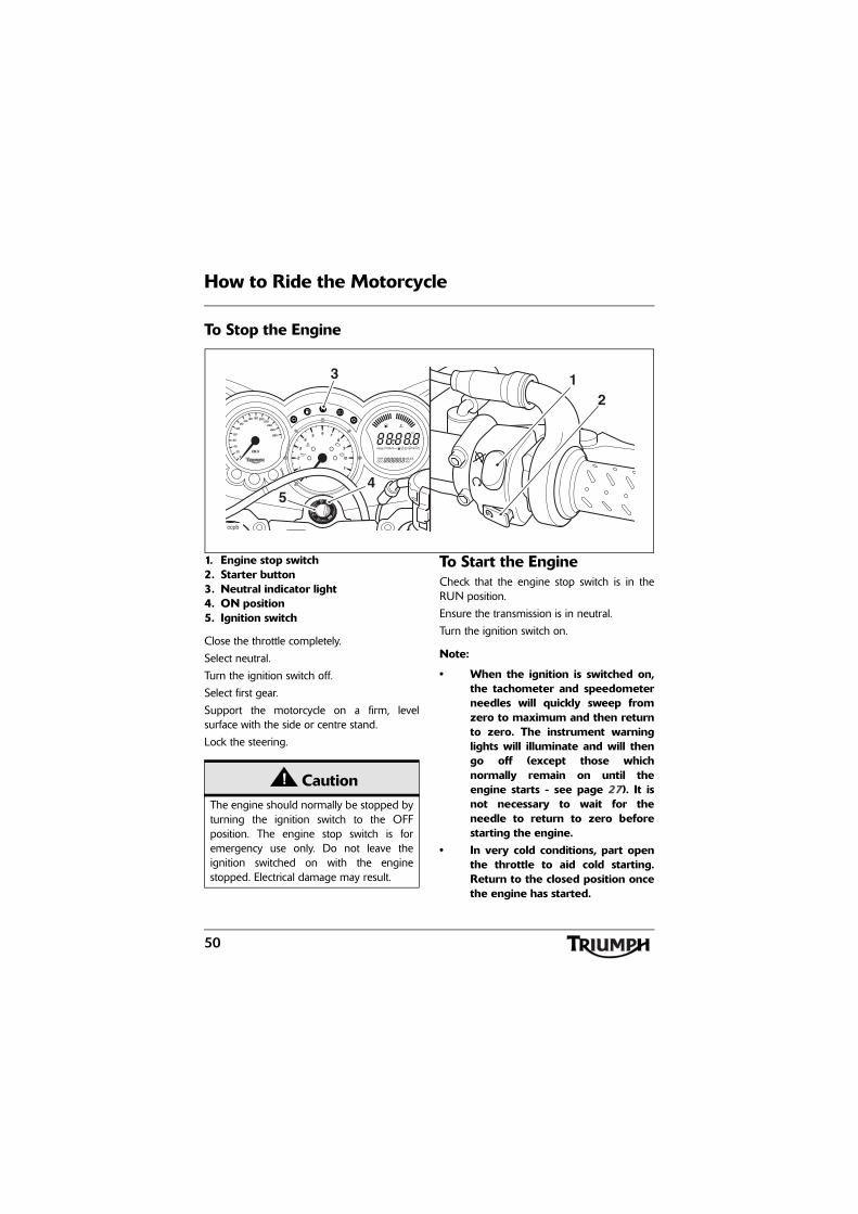
1. Engine stop switch2. Starter button3. Neutral indicator light4. ON position5. Ignition switch
Close the throttle completely.
Select neutral.
Turn the ignition switch off.
Select first gear.
Support the motorcycle on a firm, levelsurface with the side or centre stand.
Lock the steering.
To Start the EngineCheck that the engine stop switch is in theRUN position.
Ensure the transmission is in neutral.
Turn the ignition switch on.
Note:
• When the ignition is switched on,the tachometer and speedometerneedles will quickly sweep fromzero to maximum and then returnto zero. The instrument warninglights will illuminate and will thengo off (except those whichnormally remain on until theengine starts - see page 27). It isnot necessary to wait for theneedle to return to zero beforestarting the engine.
• In very cold conditions, part openthe throttle to aid cold starting.Return to the closed position oncethe engine has started.
TUV
213
45
ccpb
CautionThe engine should normally be stopped byturning the ignition switch to the OFFposition. The engine stop switch is foremergency use only. Do not leave theignition switched on with the enginestopped. Electrical damage may result.
51
How to Ride the Motorcycle
Pull the clutch lever fully into the handlebar.
Leaving the throttle fully closed, push thestarter button until the engine starts.
• The motorcycle is equipped withstarter lockout switches. The switchesprevent the electric starter fromoperating when the transmission isnot in neutral with the side standdown.
• If the side stand is extended whilstthe engine is running, and thetransmission is not in neutral thenthe engine will stop regardless ofclutch position.
Moving OffPull in the clutch lever and select first gear.Open the throttle a little and let out the clutchlever slowly. As the clutch starts to engage,open the throttle a little more, allowingenough engine speed to avoid stalling.
WarningNever start the engine or run the engine ina confined area. Exhaust fumes arepoisonous and can cause loss ofconsciousness and death within a shortperiod of time. Always operate yourmotorcycle in the open-air or in an areawith adequate ventilation.
CautionDo not operate the starter continuously formore than 5 seconds as the starter motorwill overheat and the battery will becomedischarged. Wait 15 seconds between eachoperation of the starter to allow for coolingand recovery of battery power.
Do not let the engine idle for long periodsas this may lead to overheating which willcause damage to the engine.
CautionThe low oil pressure warning light shouldgo out shortly after the engine starts.
If the low oil pressure warning light stayson after starting the engine, stop theengine immediately and investigate thecause. Running the engine with low oilpressure will cause severe engine damage.
52
How to Ride the Motorcycle
Changing Gears
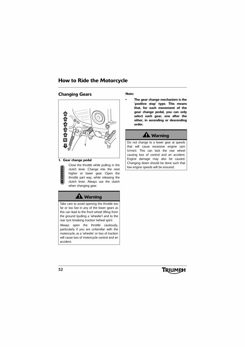
1. Gear change pedalClose the throttle while pulling in theclutch lever. Change into the nexthigher or lower gear. Open thethrottle part way, while releasing theclutch lever. Always use the clutchwhen changing gear.
Note:
• The gear change mechanism is the'positive stop' type. This meansthat, for each movement of thegear change pedal, you can onlyselect each gear, one after theother, in ascending or descendingorder.
WarningTake care to avoid opening the throttle toofar or too fast in any of the lower gears asthis can lead to the front wheel lifting fromthe ground (pulling a 'wheelie') and to therear tyre breaking traction (wheel spin).
Always open the throttle cautiously,particularly if you are unfamiliar with themotorcycle, as a 'wheelie' or loss of tractionwill cause loss of motorcycle control and anaccident.
1
43
1
5
N2
6
WarningDo not change to a lower gear at speedsthat will cause excessive engine rpm(r/min). This can lock the rear wheelcausing loss of control and an accident.Engine damage may also be caused.Changing down should be done such thatlow engine speeds will be ensured.
53
How to Ride the Motorcycle
Braking
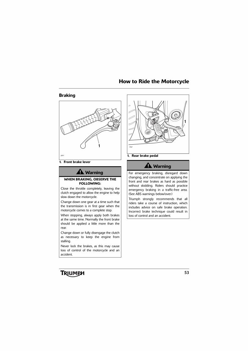
1. Front brake lever
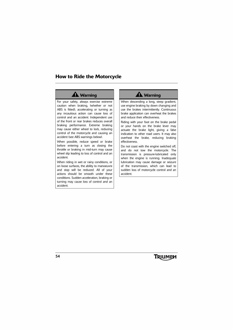
1. Rear brake pedal
WarningWHEN BRAKING, OBSERVE THE
FOLLOWING:Close the throttle completely, leaving theclutch engaged to allow the engine to helpslow down the motorcycle.
Change down one gear at a time such thatthe transmission is in first gear when themotorcycle comes to a complete stop.
When stopping, always apply both brakesat the same time. Normally the front brakeshould be applied a little more than therear.
Change down or fully disengage the clutchas necessary to keep the engine fromstalling.
Never lock the brakes, as this may causeloss of control of the motorcycle and anaccident.
2
1
3
4
1
jaim
WarningFor emergency braking, disregard downchanging, and concentrate on applying thefront and rear brakes as hard as possiblewithout skidding. Riders should practiceemergency braking in a traffic-free area.(See ABS warnings below/over.)
Triumph strongly recommends that allriders take a course of instruction, whichincludes advice on safe brake operation.Incorrect brake technique could result inloss of control and an accident.
1
ceyr
54
How to Ride the Motorcycle
WarningFor your safety, always exercise extremecaution when braking, (whether or notABS is fitted), accelerating or turning asany incautious action can cause loss ofcontrol and an accident. Independent useof the front or rear brakes reduces overallbraking performance. Extreme brakingmay cause either wheel to lock, reducingcontrol of the motorcycle and causing anaccident (see ABS warnings below).
When possible, reduce speed or brakebefore entering a turn as closing thethrottle or braking in mid-turn may causewheel slip leading to loss of control and anaccident.
When riding in wet or rainy conditions, oron loose surfaces, the ability to manoeuvreand stop will be reduced. All of youractions should be smooth under theseconditions. Sudden acceleration, braking orturning may cause loss of control and anaccident.
WarningWhen descending a long, steep gradient,use engine braking by down changing anduse the brakes intermittently. Continuousbrake application can overheat the brakesand reduce their effectiveness.
Riding with your foot on the brake pedalor your hands on the brake lever mayactuate the brake light, giving a falseindication to other road users. It may alsooverheat the brake, reducing brakingeffectiveness.
Do not coast with the engine switched off,and do not tow the motorcycle. Thetransmission is pressure-lubricated onlywhen the engine is running. Inadequatelubrication may cause damage or seizureof the transmission, which can lead tosudden loss of motorcycle control and anaccident.
55
How to Ride the Motorcycle
ABS (Anti-Lock Brake System) - Sprint GT only
ABS Warning LightThe ABS indicator lightilluminates to show that the ABSfunction is not available.
Illumination is normal after engine start-up,and until the motorcycle first reaches a speedexceeding 6 mph (10 km/h). Unless there is afault, it should not illuminate again until theengine is restarted.
If the indicator light becomes illuminated atany other time while riding, it indicates thatthe ABS has a malfunction that requiresinvestigation.
Note:
• Normally, the rider will perceiveABS operation as a harder feel or apulsation of the brake lever andpedal. As the ABS is not anintegrated braking system and itdoes not control both the frontand rear brake at the same time,this pulsation may be felt in thelever, the pedal or both.
• The ABS may be activated bysudden upward or downwardchanges in the road surface.
WarningWhere fitted, ABS prevents the wheelsfrom locking, therefore maximising theeffectiveness of the braking system inemergencies and when riding on slipperysurfaces. The potentially shorter brakingdistances ABS allows under certainconditions are not a substitute for goodriding practice.
Always ride within the legal speed limit.
Never ride without due care and attentionand always reduce speed in considerationof weather, road and traffic conditions.
Take care when cornering. If the brakes areapplied in a corner, ABS will not be able tocounteract the weight and momentum ofthe motorcycle. This can result in loss ofcontrol and an accident.
Under some circumstances it is possiblethat a motorcycle equipped with ABS mayrequire a longer stopping distance than anequivalent motorcycle without ABS.
WarningIf the ABS is not functioning, the brakesystem will continue to function as anon-ABS braking system. Do not continueto ride for longer than is necessary with theindicator light illuminated. Contact anauthorised Triumph dealer as soon aspossible to have the fault checked andrectified. In this situation, braking too hardwill cause the wheels to lock resulting inloss of control and an accident.
56
How to Ride the Motorcycle
Parking
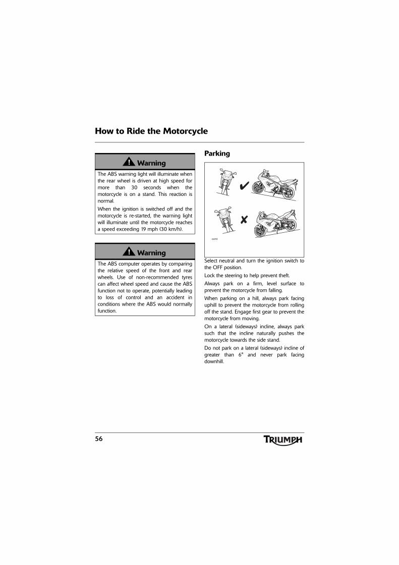
Select neutral and turn the ignition switch tothe OFF position.
Lock the steering to help prevent theft.
Always park on a firm, level surface toprevent the motorcycle from falling.
When parking on a hill, always park facinguphill to prevent the motorcycle from rollingoff the stand. Engage first gear to prevent themotorcycle from moving.
On a lateral (sideways) incline, always parksuch that the incline naturally pushes themotorcycle towards the side stand.
Do not park on a lateral (sideways) incline ofgreater than 6° and never park facingdownhill.
WarningThe ABS warning light will illuminate whenthe rear wheel is driven at high speed formore than 30 seconds when themotorcycle is on a stand. This reaction isnormal.
When the ignition is switched off and themotorcycle is re-started, the warning lightwill illuminate until the motorcycle reachesa speed exceeding 19 mph (30 km/h).
WarningThe ABS computer operates by comparingthe relative speed of the front and rearwheels. Use of non-recommended tyrescan affect wheel speed and cause the ABSfunction not to operate, potentially leadingto loss of control and an accident inconditions where the ABS would normallyfunction.
ccmt
57
How to Ride the Motorcycle
Note:
• When parking near traffic at night,or when parking in a locationwhere parking lights are requiredby law, leave the tail, licence plateand position lights on by turningthe ignition switch to P (Park).
Do not leave the switch in the P position forlong periods of time as this will discharge thebattery.
Ensure that the side stand is fully retractedbefore riding off.
WarningDo not park on a soft or on a steeplyinclined surface. Parking under theseconditions may cause the motorcycle to fallover causing damage to property andpersonal injury.
WarningPetrol is extremely flammable and can beexplosive under certain conditions. Ifparking inside a garage or other structure,be sure it is well ventilated and themotorcycle is not close to any source offlame or sparks. This includes anyappliance with a pilot light.
Failure to follow the above advice maycause a fire resulting in damage toproperty or personal injury.
WarningThe engine and exhaust system will be hotafter riding. DO NOT park wherepedestrians and children are likely to touchthe motorcycle.
Touching any part of the engine or exhaustsystem when hot may cause unprotectedskin to become burnt.
58
How to Ride the Motorcycle
Considerations for High-Speed Operation
GeneralEnsure the motorcycle has been maintainedaccording to the scheduled maintenancechart.
SteeringCheck that the handlebar turns smoothlywithout excessive free play or tight spots.Ensure that the control cables do not restrictthe steering in any way.
LuggageMake certain that any luggage containers areclosed, locked and securely fitted to themotorcycle. Ensure panniers are evenly loaded.Ensure the motorcycle is not overloaded.
WarningThis Triumph motorcycle should beoperated within the legal speed limits forthe particular road travelled. Operating amotorcycle at high speeds can bepotentially dangerous since the timeavailable to react to given traffic situationsis greatly reduced as road speed increases.Always reduce speed in consideration ofweather and traffic conditions.
WarningOnly operate this Triumph motorcycle athigh speed in closed-course on-roadcompetition or on closed-course racetracks.High-speed operation should only then beattempted by riders who have beeninstructed in the techniques necessary forhigh-speed riding and are familiar with themotorcycle's characteristics in allconditions.
High-speed operation in any othercircumstances is dangerous and will lead toloss of motorcycle control and an accident.
WarningThe handling characteristics of amotorcycle at high speed may vary fromthose you are familiar with at legal roadspeeds. Do not attempt high-speedoperation unless you have receivedsufficient training and have the requiredskills as a serious accident may result fromincorrect operation.
WarningThe items listed are extremely importantand must never be neglected. A problem,which may not be noticed at normaloperating speeds, may be greatlyexaggerated at high speeds.
59
How to Ride the Motorcycle
BrakesCheck that the front and rear brakes arefunctioning properly.
On models fitted with ABS, check that thesystem is functioning by ensuring that theABS indicator light does not remainilluminated at speeds above 6 mph(10 km/h).
TyresHigh-speed operation is hard on tyres, andtyres that are in good condition are crucial toriding safely. Examine their overall condition,inflate to the correct pressure (when the tyresare cold), and check the wheel balance.Securely fit the valve caps after checking tyrepressures. Observe the information given inthe Maintenance and Specification sectionson tyre checking and tyre safety.
FuelHave sufficient fuel for the increased fuelconsumption that will result from high-speedoperation.
Engine OilMake certain that the engine oil level iscorrect. Ensure that the correct grade andtype of oil is used when topping up.
CoolantCheck that the coolant level is at the upperlevel line in the expansion tank. (Alwayscheck the level with the engine cold.)
Electrical EquipmentMake certain that the headlight, rear/brakelight, direction indicators, horn, etc. all workproperly.
MiscellaneousVisually check that all fixings are tight.
CautionIn all countries except Australia,Hong Kong, New Zealand andSouth Africa, the exhaust system for thismodel is fitted with a catalytic converter tohelp reduce exhaust emission levels. Thecatalytic converter can be permanentlydamaged if the motorcycle is allowed torun out of fuel or if the fuel level is allowedto get very low. Always ensure you haveadequate fuel for your journey.
60
How to Ride the Motorcycle
This page intentionally left blank
61
Accessories and Loading
ACCESSORIES AND LOADINGThe addition of accessories and carriage of additional weight can affect the motorcycle'shandling characteristics causing changes in stability and necessitating a reduction in speed. Thefollowing information has been prepared as a guide to the potential hazards of addingaccessories to a motorcycle and carrying passengers and additional loads.
WarningIncorrect loading may result in an unsaferiding condition leading to an accident.
Always ensure any loads carried are evenlydistributed on both sides of the motorcycle.Ensure that the load is correctly securedsuch that it will not move around while themotorcycle is in motion.
Always check the load security regularly(though not while the motorcycle is inmotion) and ensure that the load does notextend beyond the rear of the motorcycle.
Never exceed the maximum vehicleloading weight of:
• Sprint ST - 215 kg (473 lbs);
• Sprint GT - 215 kg (473 lbs).
This maximum loading weight is made upfrom the combined weight of the rider,passenger, any accessories fitted and anyload carried.
WarningDo not install accessories or carry luggagethat impairs the control of the motorcycle.Make sure that you have not adverselyaffected the visibility of any lightingcomponent, road clearance, bankingcapability (i.e. lean angle), controloperation, wheel travel, ABS where fitted,front fork movement, visibility in anydirection, or any other aspect of themotorcycle's operation.
62
Accessories and Loading
WarningNever ride an accessory equippedmotorcycle, or a motorcycle carrying apayload of any kind, at speeds above80 mph (130 km/h). In either/both ofthese conditions, speeds in excess of80 mph (130 km/h) should not beattempted even where the legal speedlimit permits this.
The presence of accessories and/orpayload will cause changes in the stabilityand handling of the motorcycle.
Failure to allow for changes in motorcyclestability may lead to loss of control or anaccident. Remember that the 80 mph(130 km/h) absolute limit will reduce bythe fitting of non-approved accessories,incorrect loading, worn tyres, overallmotorcycle condition and poor road orweather conditions.
WarningThis motorcycle must not be operatedabove the legal road speed limit except inauthorised closed-course conditions.
WarningOnly operate this Triumph motorcycle athigh speed in closed-course on-roadcompetition or on closed-course racetracks.High-speed operation should only then beattempted by riders who have beeninstructed in the techniques necessary forhigh-speed riding and are familiar with themotorcycle's characteristics in allconditions.
High-speed operation in any othercircumstances is dangerous and will lead toloss of motorcycle control and an accident.
WarningYour passenger should be instructed thathe or she can cause loss of motorcyclecontrol by making sudden movements orby adopting an incorrect seated position.
The rider should instruct the passenger asfollows:
• It is important that the passengersits still while the motorcycle is inmotion and does not interferewith the operation of themotorcycle.
• To keep his or her feet on thepassenger footrests and to firmlyhold onto the seat strap or therider's waist or hips.
• Advise the passenger to lean withthe rider when travelling aroundcorners and not to lean unless therider does so.
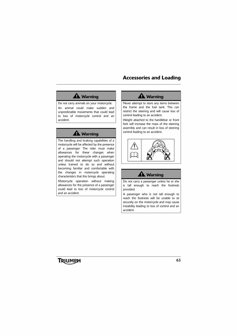
63
Accessories and Loading
WarningDo not carry animals on your motorcycle.
An animal could make sudden andunpredictable movements that could leadto loss of motorcycle control and anaccident.
WarningThe handling and braking capabilities of amotorcycle will be affected by the presenceof a passenger. The rider must makeallowances for these changes whenoperating the motorcycle with a passengerand should not attempt such operationunless trained to do so and withoutbecoming familiar and comfortable withthe changes in motorcycle operatingcharacteristics that this brings about.
Motorcycle operation without makingallowances for the presence of a passengercould lead to loss of motorcycle controland an accident.
WarningNever attempt to store any items betweenthe frame and the fuel tank. This canrestrict the steering and will cause loss ofcontrol leading to an accident.
Weight attached to the handlebar or frontfork will increase the mass of the steeringassembly and can result in loss of steeringcontrol leading to an accident.
WarningDo not carry a passenger unless he or sheis tall enough to reach the footrestsprovided.
A passenger who is not tall enough toreach the footrests will be unable to sitsecurely on the motorcycle and may causeinstability leading to loss of control and anaccident.
64
Accessories and Loading
WarningIf the passenger seat or rack (rack onSprint GT models) are used to carry smallobjects, they must not exceed a totalmaximum of 5 kg in weight (combined onthe seat and rack on Sprint GT models),must not impair control of the motorcycle,must be securely attached and must notextend beyond the rear or sides of themotorcycle.
Carriage of objects in excess of 5 kg inweight, that are insecure, impair control orextend beyond the rear or sides of themotorcycle may lead to loss of motorcyclecontrol and an accident.
Even if small objects are correctly loadedonto the rear seat or rack (on Sprint GTmodels), the maximum speed of themotorcycle must be reduced to 80 mph(130 km/h).
CautionSprint ST only: Do not allow luggage torest on or against the upper portion of therear bodywork.
Allowing luggage to rest on or against theupper portion of the rear bodywork couldclose the air gap between the bodyworkand the exhaust potentially causing thebodywork to become damaged byoverheating.
65
Maintenance and Adjustment
MAINTENANCE AND ADJUSTMENT
Table of ContentsScheduled Maintenance. . . . . . . . . . . . . . . . . . . . . . . . . . . . . . . . . . . . . . . . . . . . . . . . . . . . . . . 68
Engine Oil . . . . . . . . . . . . . . . . . . . . . . . . . . . . . . . . . . . . . . . . . . . . . . . . . . . . . . . . . . . . . . . . . . .71
Oil Level Inspection. . . . . . . . . . . . . . . . . . . . . . . . . . . . . . . . . . . . . . . . . . . . . . . . . . . . . . . .71Oil and Oil Filter Change . . . . . . . . . . . . . . . . . . . . . . . . . . . . . . . . . . . . . . . . . . . . . . . . . . 73Oil Specification and Grade . . . . . . . . . . . . . . . . . . . . . . . . . . . . . . . . . . . . . . . . . . . . . . . . 74Disposal of Used Engine Oil and Oil Filters . . . . . . . . . . . . . . . . . . . . . . . . . . . . . . . . . . . . 74
Cooling System. . . . . . . . . . . . . . . . . . . . . . . . . . . . . . . . . . . . . . . . . . . . . . . . . . . . . . . . . . . . . . 75
Corrosion Inhibitors . . . . . . . . . . . . . . . . . . . . . . . . . . . . . . . . . . . . . . . . . . . . . . . . . . . . . . . 75Coolant Level Inspection . . . . . . . . . . . . . . . . . . . . . . . . . . . . . . . . . . . . . . . . . . . . . . . . . . . 76Coolant Level Adjustment. . . . . . . . . . . . . . . . . . . . . . . . . . . . . . . . . . . . . . . . . . . . . . . . . . 76Coolant Change . . . . . . . . . . . . . . . . . . . . . . . . . . . . . . . . . . . . . . . . . . . . . . . . . . . . . . . . . 77Radiator and Hoses . . . . . . . . . . . . . . . . . . . . . . . . . . . . . . . . . . . . . . . . . . . . . . . . . . . . . . . 77
Throttle Control . . . . . . . . . . . . . . . . . . . . . . . . . . . . . . . . . . . . . . . . . . . . . . . . . . . . . . . . . . . . . 78
Inspection. . . . . . . . . . . . . . . . . . . . . . . . . . . . . . . . . . . . . . . . . . . . . . . . . . . . . . . . . . . . . . . 78Adjustment . . . . . . . . . . . . . . . . . . . . . . . . . . . . . . . . . . . . . . . . . . . . . . . . . . . . . . . . . . . . . 79
Clutch . . . . . . . . . . . . . . . . . . . . . . . . . . . . . . . . . . . . . . . . . . . . . . . . . . . . . . . . . . . . . . . . . . . . . 80
Inspection. . . . . . . . . . . . . . . . . . . . . . . . . . . . . . . . . . . . . . . . . . . . . . . . . . . . . . . . . . . . . . . 80Adjustment . . . . . . . . . . . . . . . . . . . . . . . . . . . . . . . . . . . . . . . . . . . . . . . . . . . . . . . . . . . . . 80
Drive Chain. . . . . . . . . . . . . . . . . . . . . . . . . . . . . . . . . . . . . . . . . . . . . . . . . . . . . . . . . . . . . . . . . 81
Chain Lubrication . . . . . . . . . . . . . . . . . . . . . . . . . . . . . . . . . . . . . . . . . . . . . . . . . . . . . . . . 81Chain Free-Movement Inspection . . . . . . . . . . . . . . . . . . . . . . . . . . . . . . . . . . . . . . . . . . . 82Chain Free-Movement Adjustment . . . . . . . . . . . . . . . . . . . . . . . . . . . . . . . . . . . . . . . . . . 82Chain and Sprocket Wear Inspection . . . . . . . . . . . . . . . . . . . . . . . . . . . . . . . . . . . . . . . . . 83
Brakes . . . . . . . . . . . . . . . . . . . . . . . . . . . . . . . . . . . . . . . . . . . . . . . . . . . . . . . . . . . . . . . . . . . . . 84
Brake Wear Inspection . . . . . . . . . . . . . . . . . . . . . . . . . . . . . . . . . . . . . . . . . . . . . . . . . . . . 84Breaking-in New Brake Pads and Discs . . . . . . . . . . . . . . . . . . . . . . . . . . . . . . . . . . . . . . . 85Brake Pad Wear Compensation . . . . . . . . . . . . . . . . . . . . . . . . . . . . . . . . . . . . . . . . . . . . . 85Disc Brake Fluid . . . . . . . . . . . . . . . . . . . . . . . . . . . . . . . . . . . . . . . . . . . . . . . . . . . . . . . . . . 86Brake Fluid Level Inspection and Adjustment . . . . . . . . . . . . . . . . . . . . . . . . . . . . . . . . . . 87Brake Light Switches . . . . . . . . . . . . . . . . . . . . . . . . . . . . . . . . . . . . . . . . . . . . . . . . . . . . . . 89
66
Maintenance and Adjustment
Steering/Wheel Bearings . . . . . . . . . . . . . . . . . . . . . . . . . . . . . . . . . . . . . . . . . . . . . . . . . . . . . . 90
Steering Inspection . . . . . . . . . . . . . . . . . . . . . . . . . . . . . . . . . . . . . . . . . . . . . . . . . . . . . . . 90Inspecting the Steering (Headstock) Bearings for Free Play . . . . . . . . . . . . . . . . . . . . . . . 90Wheel Bearings Inspection . . . . . . . . . . . . . . . . . . . . . . . . . . . . . . . . . . . . . . . . . . . . . . . . . 91
Front Suspension . . . . . . . . . . . . . . . . . . . . . . . . . . . . . . . . . . . . . . . . . . . . . . . . . . . . . . . . . . . . 91
Front Fork Inspection. . . . . . . . . . . . . . . . . . . . . . . . . . . . . . . . . . . . . . . . . . . . . . . . . . . . . . 91Suspension Setting Chart . . . . . . . . . . . . . . . . . . . . . . . . . . . . . . . . . . . . . . . . . . . . . . . . . . 92Front Suspension Settings . . . . . . . . . . . . . . . . . . . . . . . . . . . . . . . . . . . . . . . . . . . . . . . . . . 92Spring Pre-Load Adjustment. . . . . . . . . . . . . . . . . . . . . . . . . . . . . . . . . . . . . . . . . . . . . . . . 93
Rear Suspension Adjustment . . . . . . . . . . . . . . . . . . . . . . . . . . . . . . . . . . . . . . . . . . . . . . . . . . . 93
Rebound Damping Adjustment . . . . . . . . . . . . . . . . . . . . . . . . . . . . . . . . . . . . . . . . . . . . . 93Spring Pre-Load Adjustment - Sprint ST . . . . . . . . . . . . . . . . . . . . . . . . . . . . . . . . . . . . . . 94
Tyres . . . . . . . . . . . . . . . . . . . . . . . . . . . . . . . . . . . . . . . . . . . . . . . . . . . . . . . . . . . . . . . . . . . . . . 95
Tyre Inflation Pressures . . . . . . . . . . . . . . . . . . . . . . . . . . . . . . . . . . . . . . . . . . . . . . . . . . . . 95Tyre Wear. . . . . . . . . . . . . . . . . . . . . . . . . . . . . . . . . . . . . . . . . . . . . . . . . . . . . . . . . . . . . . . 96Minimum Recommended Tread Depth . . . . . . . . . . . . . . . . . . . . . . . . . . . . . . . . . . . . . . . 96Tyre Replacement . . . . . . . . . . . . . . . . . . . . . . . . . . . . . . . . . . . . . . . . . . . . . . . . . . . . . . . . 97
Battery . . . . . . . . . . . . . . . . . . . . . . . . . . . . . . . . . . . . . . . . . . . . . . . . . . . . . . . . . . . . . . . . . . . . . 99
Battery Removal. . . . . . . . . . . . . . . . . . . . . . . . . . . . . . . . . . . . . . . . . . . . . . . . . . . . . . . . . . 99Battery Disposal . . . . . . . . . . . . . . . . . . . . . . . . . . . . . . . . . . . . . . . . . . . . . . . . . . . . . . . . . 100Battery Maintenance . . . . . . . . . . . . . . . . . . . . . . . . . . . . . . . . . . . . . . . . . . . . . . . . . . . . . 100Battery Discharge . . . . . . . . . . . . . . . . . . . . . . . . . . . . . . . . . . . . . . . . . . . . . . . . . . . . . . . 100Battery Discharge During Storage and Infrequent Use of the Motorcycle . . . . . . . . . . . .101Battery Charging . . . . . . . . . . . . . . . . . . . . . . . . . . . . . . . . . . . . . . . . . . . . . . . . . . . . . . . . .101Battery Installation . . . . . . . . . . . . . . . . . . . . . . . . . . . . . . . . . . . . . . . . . . . . . . . . . . . . . . . 102
Fuse Box . . . . . . . . . . . . . . . . . . . . . . . . . . . . . . . . . . . . . . . . . . . . . . . . . . . . . . . . . . . . . . . . . . 102
Fuse Identification - Sprint ST . . . . . . . . . . . . . . . . . . . . . . . . . . . . . . . . . . . . . . . . . . . . . . 103Fuse Identification - Sprint GT . . . . . . . . . . . . . . . . . . . . . . . . . . . . . . . . . . . . . . . . . . . . . 104
Headlights . . . . . . . . . . . . . . . . . . . . . . . . . . . . . . . . . . . . . . . . . . . . . . . . . . . . . . . . . . . . . . . . . 105
Headlight Adjustment . . . . . . . . . . . . . . . . . . . . . . . . . . . . . . . . . . . . . . . . . . . . . . . . . . . . 106Main Beam Horizontal Adjustment . . . . . . . . . . . . . . . . . . . . . . . . . . . . . . . . . . . . . . . . . 106Main Beam Vertical Adjustment . . . . . . . . . . . . . . . . . . . . . . . . . . . . . . . . . . . . . . . . . . . . 106Dipped Headlight Vertical Adjustment . . . . . . . . . . . . . . . . . . . . . . . . . . . . . . . . . . . . . . . 107Dipped Headlight Horizontal Adjustment . . . . . . . . . . . . . . . . . . . . . . . . . . . . . . . . . . . . 107Dipped Headlight Bulb Replacement . . . . . . . . . . . . . . . . . . . . . . . . . . . . . . . . . . . . . . . . 108
67
Maintenance and Adjustment
Main Beam Bulb Replacement . . . . . . . . . . . . . . . . . . . . . . . . . . . . . . . . . . . . . . . . . . . . . 108Position Lamp Bulb Replacement . . . . . . . . . . . . . . . . . . . . . . . . . . . . . . . . . . . . . . . . . . . 109
Rear Light . . . . . . . . . . . . . . . . . . . . . . . . . . . . . . . . . . . . . . . . . . . . . . . . . . . . . . . . . . . . . . . . . 109
Direction Indicator Lights . . . . . . . . . . . . . . . . . . . . . . . . . . . . . . . . . . . . . . . . . . . . . . . . . . . . . .110
Front Indicator Bulb Replacement. . . . . . . . . . . . . . . . . . . . . . . . . . . . . . . . . . . . . . . . . . . .110Rear Indicator Bulb Replacement . . . . . . . . . . . . . . . . . . . . . . . . . . . . . . . . . . . . . . . . . . . .110
Licence Plate Light . . . . . . . . . . . . . . . . . . . . . . . . . . . . . . . . . . . . . . . . . . . . . . . . . . . . . . . . . . .111
Bulb Replacement . . . . . . . . . . . . . . . . . . . . . . . . . . . . . . . . . . . . . . . . . . . . . . . . . . . . . . . .111
Windscreen Cleaning . . . . . . . . . . . . . . . . . . . . . . . . . . . . . . . . . . . . . . . . . . . . . . . . . . . . . . . . .111
Cleaning . . . . . . . . . . . . . . . . . . . . . . . . . . . . . . . . . . . . . . . . . . . . . . . . . . . . . . . . . . . . . . . . . . .112
Preparation for Washing . . . . . . . . . . . . . . . . . . . . . . . . . . . . . . . . . . . . . . . . . . . . . . . . . . .112Where to be Careful . . . . . . . . . . . . . . . . . . . . . . . . . . . . . . . . . . . . . . . . . . . . . . . . . . . . . .113After Washing . . . . . . . . . . . . . . . . . . . . . . . . . . . . . . . . . . . . . . . . . . . . . . . . . . . . . . . . . . .113Seat Care . . . . . . . . . . . . . . . . . . . . . . . . . . . . . . . . . . . . . . . . . . . . . . . . . . . . . . . . . . . . . . .113Unpainted Aluminium Items. . . . . . . . . . . . . . . . . . . . . . . . . . . . . . . . . . . . . . . . . . . . . . . .114Cleaning of the Exhaust System . . . . . . . . . . . . . . . . . . . . . . . . . . . . . . . . . . . . . . . . . . . . .114Washing . . . . . . . . . . . . . . . . . . . . . . . . . . . . . . . . . . . . . . . . . . . . . . . . . . . . . . . . . . . . . . . .114Drying . . . . . . . . . . . . . . . . . . . . . . . . . . . . . . . . . . . . . . . . . . . . . . . . . . . . . . . . . . . . . . . . .114Protecting. . . . . . . . . . . . . . . . . . . . . . . . . . . . . . . . . . . . . . . . . . . . . . . . . . . . . . . . . . . . . . .114
68
Maintenance and Adjustment
Scheduled MaintenanceTo maintain the motorcycle in a safe andreliable condition, the maintenance andadjustments outlined in this section must becarried out as specified in the schedule ofdaily checks, and also in line with thescheduled maintenance chart. Theinformation that follows describes theprocedures to follow when carrying out thedaily checks and some simple maintenanceand adjustment items.
Triumph Motorcycles cannot accept anyresponsibility for damage or injury resultingfrom incorrect maintenance or improperadjustment carried out by the owner.
WarningSpecial tools, knowledge and training arerequired in order to correctly carry out themaintenance items listed in the scheduledmaintenance chart. Only an authorisedTriumph dealer will have this knowledgeand equipment.
Since incorrect or neglected maintenancecan lead to a dangerous riding condition,always have an authorised Triumph dealercarry out the scheduled maintenance ofthis motorcycle.
WarningAll maintenance is vitally important andmust not be neglected. Incorrectmaintenance or adjustment may cause oneor more parts of the motorcycle tomalfunction. A malfunctioning motorcyclemay lead to loss of control and an accident.
Weather, terrain and geographical locationaffects maintenance. The maintenanceschedule should be adjusted to match theparticular environment in which the vehicleis used and the demands of the individualowner.
Since incorrect or neglected maintenancecan lead to a dangerous riding condition,always have an authorised Triumph dealercarry out the scheduled maintenance ofthis motorcycle.
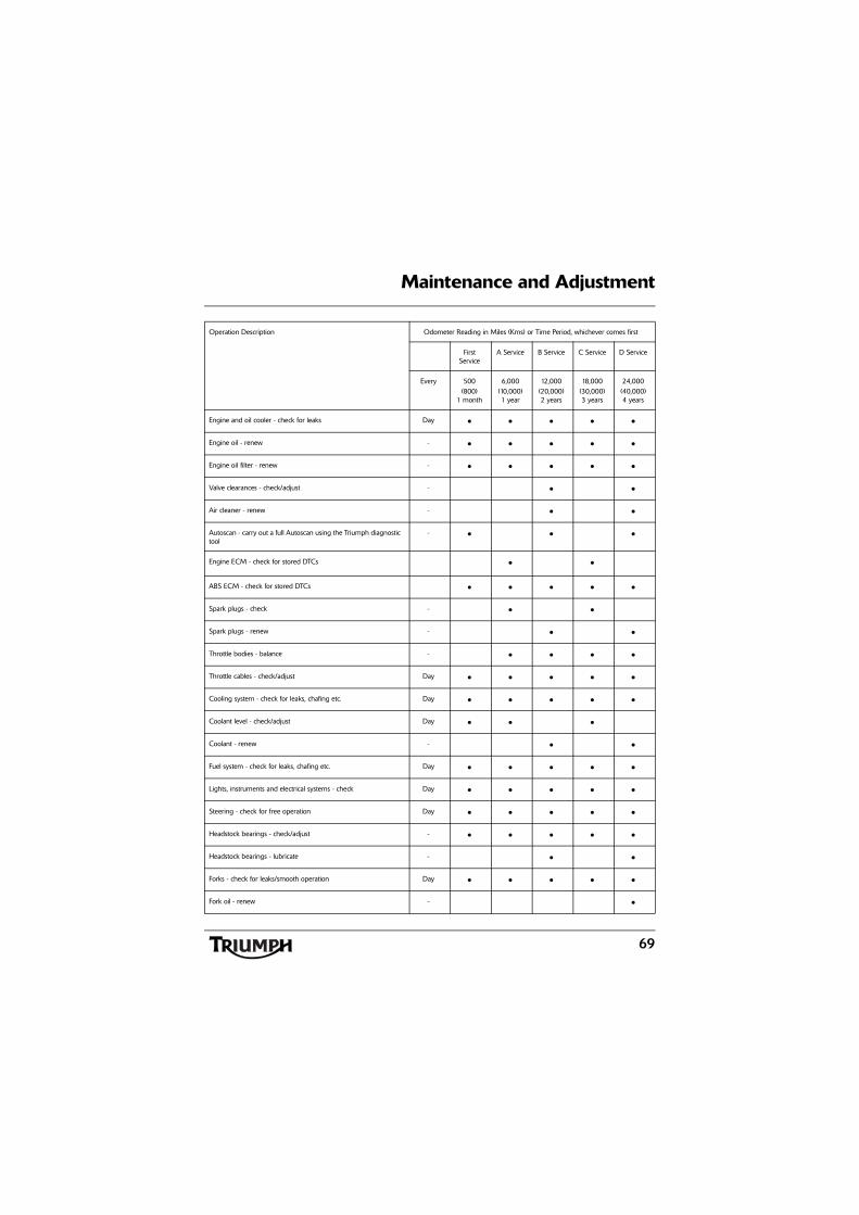
69
Maintenance and Adjustment
Operation Description Odometer Reading in Miles (Kms) or Time Period, whichever comes first
First Service
A Service B Service C Service D Service
Every 500(800)
1 month
6,000(10,000)1 year
12,000(20,000)2 years
18,000(30,000)3 years
24,000(40,000)4 years
Engine and oil cooler - check for leaks Day • • • • •
Engine oil - renew - • • • • •
Engine oil filter - renew - • • • • •
Valve clearances - check/adjust - • •
Air cleaner - renew - • •
Autoscan - carry out a full Autoscan using the Triumph diagnostic tool
- • • •
Engine ECM - check for stored DTCs • •
ABS ECM - check for stored DTCs • • • • •
Spark plugs - check - • •
Spark plugs - renew - • •
Throttle bodies - balance - • • • •
Throttle cables - check/adjust Day • • • • •
Cooling system - check for leaks, chafing etc. Day • • • • •
Coolant level - check/adjust Day • • •
Coolant - renew - • •
Fuel system - check for leaks, chafing etc. Day • • • • •
Lights, instruments and electrical systems - check Day • • • • •
Steering - check for free operation Day • • • • •
Headstock bearings - check/adjust - • • • • •
Headstock bearings - lubricate - • •
Forks - check for leaks/smooth operation Day • • • • •
Fork oil - renew - •
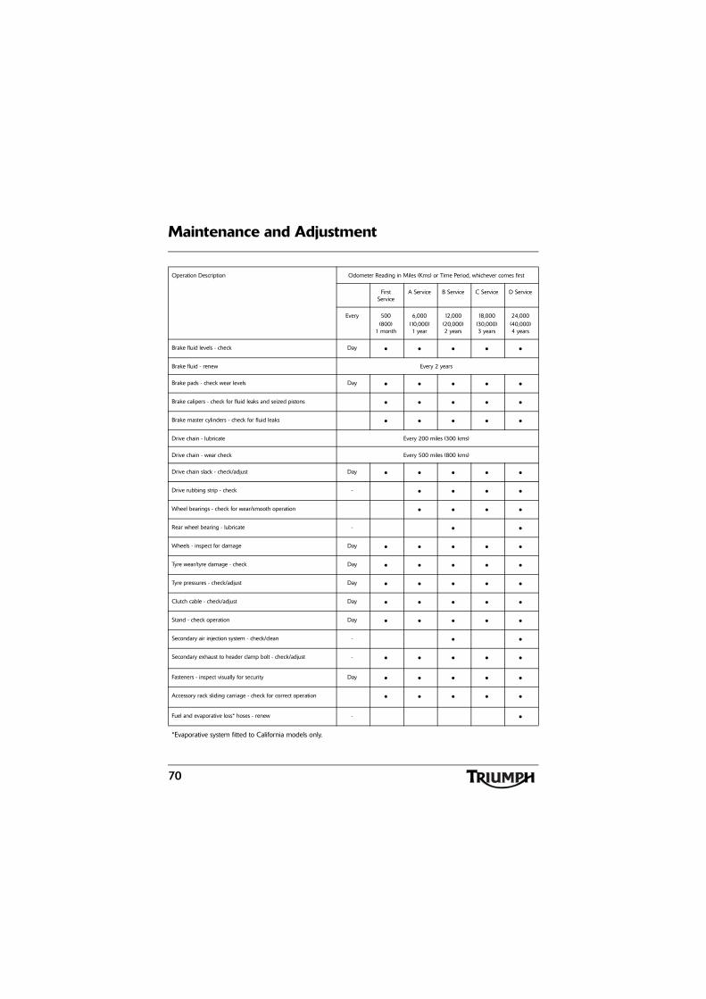
70
Maintenance and Adjustment
Brake fluid levels - check Day • • • • •
Brake fluid - renew Every 2 years
Brake pads - check wear levels Day • • • • •
Brake calipers - check for fluid leaks and seized pistons • • • • •
Brake master cylinders - check for fluid leaks • • • • •
Drive chain - lubricate Every 200 miles (300 kms)
Drive chain - wear check Every 500 miles (800 kms)
Drive chain slack - check/adjust Day • • • • •
Drive rubbing strip - check - • • • •
Wheel bearings - check for wear/smooth operation • • • •
Rear wheel bearing - lubricate - • •
Wheels - inspect for damage Day • • • • •
Tyre wear/tyre damage - check Day • • • • •
Tyre pressures - check/adjust Day • • • • •
Clutch cable - check/adjust Day • • • • •
Stand - check operation Day • • • • •
Secondary air injection system - check/clean - • •
Secondary exhaust to header clamp bolt - check/adjust - • • • • •
Fasteners - inspect visually for security Day • • • • •
Accessory rack sliding carriage - check for correct operation • • • • •
Fuel and evaporative loss* hoses - renew - •
*Evaporative system fitted to California models only.
Operation Description Odometer Reading in Miles (Kms) or Time Period, whichever comes first
First Service
A Service B Service C Service D Service
Every 500(800)
1 month
6,000(10,000)1 year
12,000(20,000)2 years
18,000(30,000)3 years
24,000(40,000)4 years
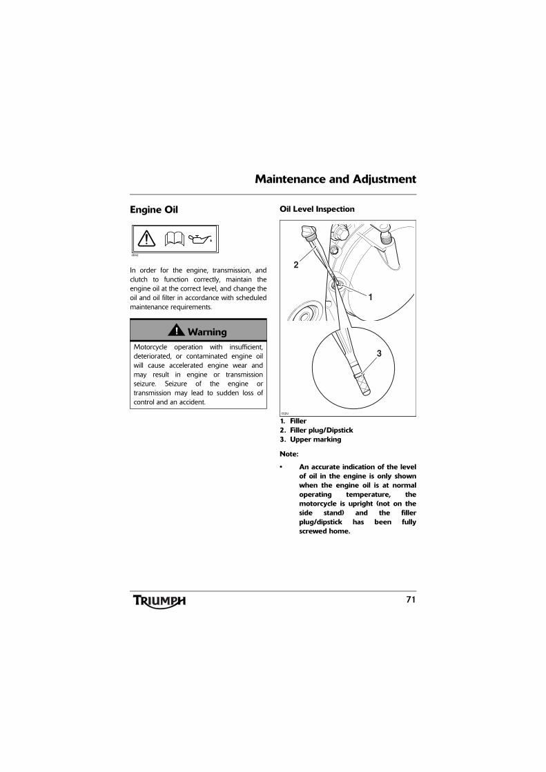
71
Maintenance and Adjustment
Engine Oil
In order for the engine, transmission, andclutch to function correctly, maintain theengine oil at the correct level, and change theoil and oil filter in accordance with scheduledmaintenance requirements.
Oil Level Inspection
1. Filler2. Filler plug/Dipstick3. Upper marking
Note:
• An accurate indication of the levelof oil in the engine is only shownwhen the engine oil is at normaloperating temperature, themotorcycle is upright (not on theside stand) and the fillerplug/dipstick has been fullyscrewed home.
WarningMotorcycle operation with insufficient,deteriorated, or contaminated engine oilwill cause accelerated engine wear andmay result in engine or transmissionseizure. Seizure of the engine ortransmission may lead to sudden loss ofcontrol and an accident.
cbnz
ccpu
3
2
1
72
Maintenance and Adjustment
Start the engine and run at idle forapproximately five minutes.
Stop the engine and wait for three minutes toallow the oil to settle.
With the motorcycle upright, remove the fillerplug/dipstick, wipe the blade clean and screwit fully home.
Remove the filler plug/dipstick.
The oil level is indicated by lines on the fillerplug/dipstick. When full, the indicated oillevel must be level with the upper markingon the dipstick.
If the oil level is below the lower marking,add oil a little at a time until the correct levelis reached. Once the correct level is reached,re-fit the filler plug/dipstick.
WarningNever start the engine or run the engine ina confined area. Exhaust fumes arepoisonous and can cause loss ofconsciousness and death within a shortperiod of time. Always operate yourmotorcycle in the open-air or in an areawith adequate ventilation.
CautionRunning the engine with insufficient oil willcause engine damage. If the low oilpressure indicator remains on, stop theengine immediately and investigate thecause.
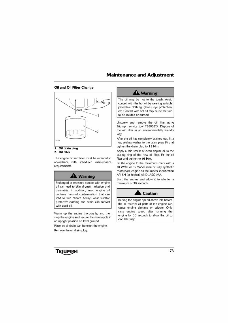
73
Maintenance and Adjustment
Oil and Oil Filter Change
1. Oil drain plug2. Oil filter
The engine oil and filter must be replaced inaccordance with scheduled maintenancerequirements.
Warm up the engine thoroughly, and thenstop the engine and secure the motorcycle inan upright position on level ground.
Place an oil drain pan beneath the engine.
Remove the oil drain plug.
Unscrew and remove the oil filter usingTriumph service tool T3880313. Dispose ofthe old filter in an environmentally friendlyway.
After the oil has completely drained out, fit anew sealing washer to the drain plug. Fit andtighten the drain plug to 25 Nm.
Apply a thin smear of clean engine oil to thesealing ring of the new oil filter. Fit the oilfilter and tighten to 10 Nm.
Fill the engine to the maximum mark with a10 W/40 or 15 W/50 semi or fully syntheticmotorcycle engine oil that meets specificationAPI SH (or higher) AND JASO MA.
Start the engine and allow it to idle for aminimum of 30 seconds.
WarningProlonged or repeated contact with engineoil can lead to skin dryness, irritation anddermatitis. In addition, used engine oilcontains harmful contamination that canlead to skin cancer. Always wear suitableprotective clothing and avoid skin contactwith used oil.
ccog
1
2
WarningThe oil may be hot to the touch. Avoidcontact with the hot oil by wearing suitableprotective clothing, gloves, eye protection,etc. Contact with hot oil may cause the skinto be scalded or burned.
CautionRaising the engine speed above idle beforethe oil reaches all parts of the engine cancause engine damage or seizure. Onlyraise engine speed after running theengine for 30 seconds to allow the oil tocirculate fully.
74
Maintenance and Adjustment
Ensure that the low oil pressure warning lightextinguishes shortly after starting.
Turn off the ignition, check the oil level usingthe method previously described, and top upto between the minimum and maximumlevel lines on the dipstick.
Oil Specification and GradeTriumph high performance fuel injectedengines are designed to use 10 W/40 or15 W/50 semi or fully synthetic motorcycleengine oil that meets specification API SH (orhigher) AND JASO MA.
Do not add any chemical additives to theengine oil. The engine oil also lubricates theclutch and any additives could cause theclutch to slip.
Do not use mineral, vegetable, non-detergentoil, castor based oils or any oil notconforming to the required specification. Theuse of these oils may cause instant, severeengine damage.
Disposal of Used Engine Oil and Oil FiltersTo protect the environment, do not pour oilon the ground, down sewers or drains, orinto watercourses. Do not place used oil filtersin with general waste. If in doubt, contactyour local authority.
CautionIf the engine oil pressure is too low, the lowoil pressure warning light will illuminate. Ifthis light stays on when the engine isrunning, stop the engine immediately andinvestigate the cause. Running the enginewith low oil pressure will cause enginedamage.
75
Maintenance and Adjustment
Cooling System
To ensure efficient engine cooling, check thecoolant level each day before riding themotorcycle, and top up the coolant if the levelis low.
Note:
• A year-round, Hybrid Organic AcidTechnology (known as Hybrid OATor HOAT) coolant is installed in thecooling system when themotorcycle leaves the factory. It iscoloured green, contains a 50%solution of ethylene glycol basedantifreeze, and has a freezingpoint of -35°C (-31°F).
Corrosion InhibitorsTo protect the cooling system from corrosion,the use of corrosion inhibitor chemicals in thecoolant is essential.
If coolant containing a corrosion inhibitor isnot used, the cooling system will accumulaterust and scale in the water jacket and radiator.This will block the coolant passages, andconsiderably reduce the efficiency of thecooling system.
Note:
• HD4X Hybrid OAT coolant, assupplied by Triumph, is pre-mixedand does not need to be dilutedprior to filling or topping up thecooling system.
WarningHD4X Hybrid OAT coolant containscorrosion inhibitors and anti-freeze suitablefor aluminium engines and radiators.Always use the coolant in accordance withthe instructions of the manufacturer.
Coolant that contains anti-freeze andcorrosion inhibitors contains toxicchemicals that are harmful to the humanbody. Never swallow anti-freeze or any ofthe motorcycle coolant.
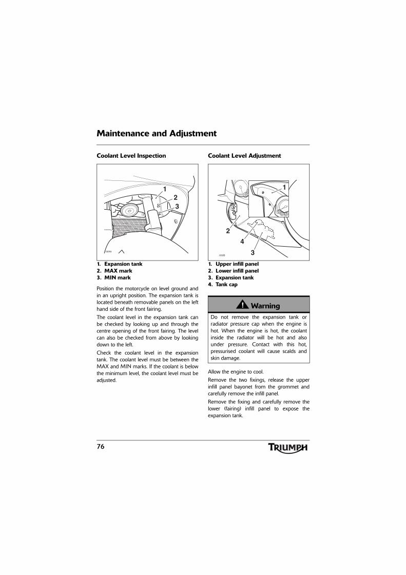
76
Maintenance and Adjustment
Coolant Level Inspection
1. Expansion tank2. MAX mark3. MIN mark
Position the motorcycle on level ground andin an upright position. The expansion tank islocated beneath removable panels on the lefthand side of the front fairing.
The coolant level in the expansion tank canbe checked by looking up and through thecentre opening of the front fairing. The levelcan also be checked from above by lookingdown to the left.
Check the coolant level in the expansiontank. The coolant level must be between theMAX and MIN marks. If the coolant is belowthe minimum level, the coolant level must beadjusted.
Coolant Level Adjustment
1. Upper infill panel2. Lower infill panel3. Expansion tank4. Tank cap
Allow the engine to cool.
Remove the two fixings, release the upperinfill panel bayonet from the grommet andcarefully remove the infill panel.
Remove the fixing and carefully remove thelower (fairing) infill panel to expose theexpansion tank.
ccno
21
3
WarningDo not remove the expansion tank orradiator pressure cap when the engine ishot. When the engine is hot, the coolantinside the radiator will be hot and alsounder pressure. Contact with this hot,pressurised coolant will cause scalds andskin damage.
ccob
1
2
4
3
77
Maintenance and Adjustment
Remove the cap from the expansion tankand add coolant mixture through the filleropening until the level reaches the MAXmark. Refit the cap.
Note:
• If the coolant level is beingchecked because the coolant hasoverheated, also check the level inthe radiator and top up ifnecessary.
• In an emergency, distilled watercan be added to the coolingsystem. However, the coolantmust then be drained andreplenished with HD4XHybrid OAT coolant as soon aspossible.
Carefully refit the infill panels, ensuring theupper infill panel bayonet fixing is secured tothe lower infill panel grommet. Tighten thefixings to 5 Nm.
Coolant ChangeHave the coolant changed by an authorisedTriumph dealer in accordance with scheduledmaintenance requirements.
Radiator and HosesCheck the radiator hoses for cracks ordeterioration, and hose clips for tightness inaccordance with scheduled maintenancerequirements. Have your authorised Triumphdealer replace any defective items.
Check the radiator grille and fins forobstructions by insects, leaves or mud. Cleanoff any obstructions with a stream oflow-pressure water.
CautionIf hard water is used in the cooling system,it will cause scale accumulation in theengine and radiator and considerablyreduce the efficiency of the cooling system.Reduced cooling system efficiency maycause the engine to overheat and suffersevere damage.
WarningThe fan operates automatically when theengine is running. Always keep hands andclothing away from the fan as contact withthe rotating fan can cause injury.
CautionUsing high-pressure water sprays, such asfrom a car wash facility or householdpressure washer, can damage the radiatorfins, cause leaks and impair the radiator'sefficiency.
Do not obstruct or deflect airflow throughthe radiator by installing unauthorisedaccessories, either in front of the radiator orbehind the cooling fan. Interference withthe radiator airflow can cause overheating,potentially resulting in engine damage.
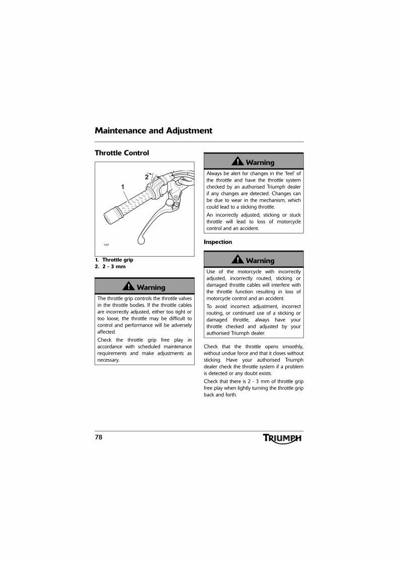
78
Maintenance and Adjustment
Throttle Control
1. Throttle grip2. 2 - 3 mm
Inspection
Check that the throttle opens smoothly,without undue force and that it closes withoutsticking. Have your authorised Triumphdealer check the throttle system if a problemis detected or any doubt exists.
Check that there is 2 - 3 mm of throttle gripfree play when lightly turning the throttle gripback and forth.
WarningThe throttle grip controls the throttle valvesin the throttle bodies. If the throttle cablesare incorrectly adjusted, either too tight ortoo loose, the throttle may be difficult tocontrol and performance will be adverselyaffected.
Check the throttle grip free play inaccordance with scheduled maintenancerequirements and make adjustments asnecessary.
ccpf
12
WarningAlways be alert for changes in the 'feel' ofthe throttle and have the throttle systemchecked by an authorised Triumph dealerif any changes are detected. Changes canbe due to wear in the mechanism, whichcould lead to a sticking throttle.
An incorrectly adjusted, sticking or stuckthrottle will lead to loss of motorcyclecontrol and an accident.
WarningUse of the motorcycle with incorrectlyadjusted, incorrectly routed, sticking ordamaged throttle cables will interfere withthe throttle function resulting in loss ofmotorcycle control and an accident.
To avoid incorrect adjustment, incorrectrouting, or continued use of a sticking ordamaged throttle, always have yourthrottle checked and adjusted by yourauthorised Triumph dealer.
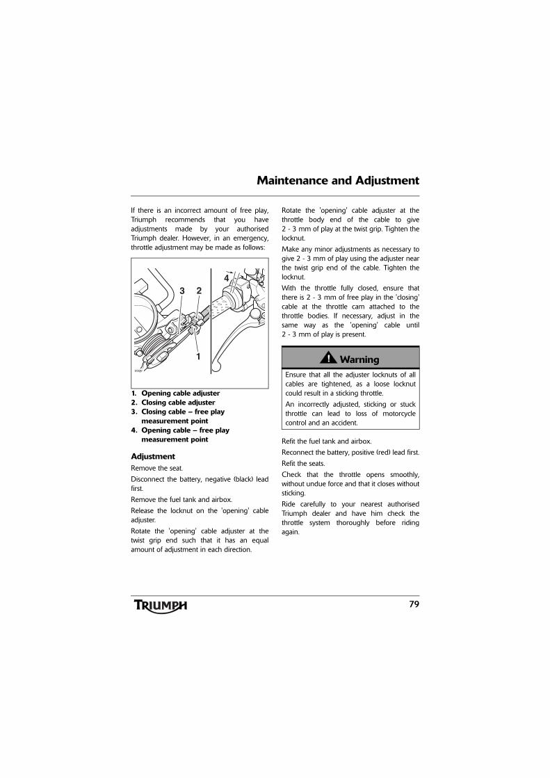
79
Maintenance and Adjustment
If there is an incorrect amount of free play,Triumph recommends that you haveadjustments made by your authorisedTriumph dealer. However, in an emergency,throttle adjustment may be made as follows:
1. Opening cable adjuster2. Closing cable adjuster3. Closing cable – free play
measurement point4. Opening cable – free play
measurement point
AdjustmentRemove the seat.
Disconnect the battery, negative (black) leadfirst.
Remove the fuel tank and airbox.
Release the locknut on the 'opening' cableadjuster.
Rotate the 'opening' cable adjuster at thetwist grip end such that it has an equalamount of adjustment in each direction.
Rotate the 'opening' cable adjuster at thethrottle body end of the cable to give2 - 3 mm of play at the twist grip. Tighten thelocknut.
Make any minor adjustments as necessary togive 2 - 3 mm of play using the adjuster nearthe twist grip end of the cable. Tighten thelocknut.
With the throttle fully closed, ensure thatthere is 2 - 3 mm of free play in the 'closing'cable at the throttle cam attached to thethrottle bodies. If necessary, adjust in thesame way as the 'opening' cable until2 - 3 mm of play is present.
Refit the fuel tank and airbox.
Reconnect the battery, positive (red) lead first.
Refit the seats.
Check that the throttle opens smoothly,without undue force and that it closes withoutsticking.
Ride carefully to your nearest authorisedTriumph dealer and have him check thethrottle system thoroughly before ridingagain.
ccqv
423
1 WarningEnsure that all the adjuster locknuts of allcables are tightened, as a loose locknutcould result in a sticking throttle.
An incorrectly adjusted, sticking or stuckthrottle can lead to loss of motorcyclecontrol and an accident.
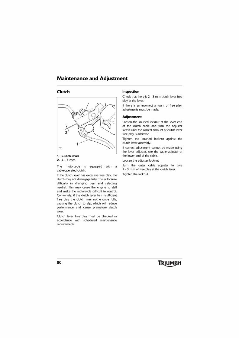
80
Maintenance and Adjustment
Clutch
1. Clutch lever2. 2 - 3 mm
The motorcycle is equipped with acable-operated clutch.
If the clutch lever has excessive free play, theclutch may not disengage fully. This will causedifficulty in changing gear and selectingneutral. This may cause the engine to stalland make the motorcycle difficult to control.Conversely, if the clutch lever has insufficientfree play the clutch may not engage fully,causing the clutch to slip, which will reduceperformance and cause premature clutchwear.
Clutch lever free play must be checked inaccordance with scheduled maintenancerequirements.
InspectionCheck that there is 2 - 3 mm clutch lever freeplay at the lever.
If there is an incorrect amount of free play,adjustments must be made.
AdjustmentLoosen the knurled locknut at the lever endof the clutch cable and turn the adjustersleeve until the correct amount of clutch leverfree play is achieved.
Tighten the knurled locknut against theclutch lever assembly.
If correct adjustment cannot be made usingthe lever adjuster, use the cable adjuster atthe lower end of the cable.
Loosen the adjuster locknut.
Turn the outer cable adjuster to give2 - 3 mm of free play at the clutch lever.
Tighten the locknut.
ccpe
2
1
81
Maintenance and Adjustment
Drive Chain
For safety and to prevent excessive wear, thedrive chain must be checked, adjusted andlubricated in accordance with scheduledmaintenance requirements. Checking,adjustment and lubrication must be carriedout more frequently for extreme conditionssuch as salty or heavily gritted roads.
If the chain is badly worn or incorrectlyadjusted (either too loose or too tight) thechain could jump off the sprockets or break.Therefore, always replace worn or damagedchains using genuine Triumph parts suppliedby an authorised Triumph dealer.
Chain LubricationLubrication is necessary every 200 miles andalso after riding in wet weather, on wet roads,or any time that the chain appears dry.
Use the special chain lubricant asrecommended in the Specification section.
Apply lubricant to the sides of the rollers thenallow the motorcycle to stand unused for atleast 8 hours (overnight is ideal). This willallow the oil to penetrate to the chain O-ringsetc.
Before riding, wipe off any excess oil.
If the chain is especially dirty, clean first andthen apply oil as mentioned above.
WarningA loose or worn chain, or a chain thatbreaks or jumps off the sprockets couldcatch on the engine sprocket or lock therear wheel.
A chain that catches on the enginesprocket will injure the rider and lead toloss of motorcycle control and an accident.
Similarly, locking the rear wheel will lead toloss of motorcycle control and an accident.
CautionDo not use a pressure wash to clean thechain as this may cause damage to thechain components.
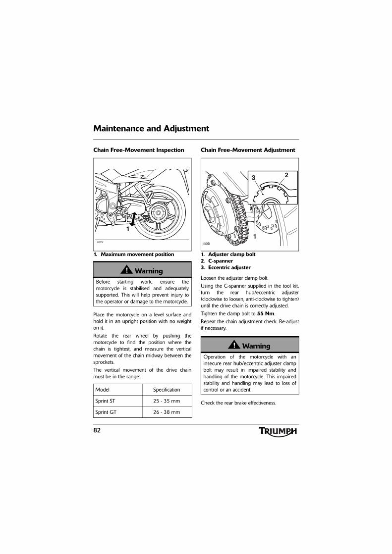
82
Maintenance and Adjustment
Chain Free-Movement Inspection
1. Maximum movement position
Place the motorcycle on a level surface andhold it in an upright position with no weighton it.
Rotate the rear wheel by pushing themotorcycle to find the position where thechain is tightest, and measure the verticalmovement of the chain midway between thesprockets.
The vertical movement of the drive chainmust be in the range:
Chain Free-Movement Adjustment
1. Adjuster clamp bolt 2. C-spanner3. Eccentric adjuster
Loosen the adjuster clamp bolt.
Using the C-spanner supplied in the tool kit,turn the rear hub/eccentric adjuster(clockwise to loosen, anti-clockwise to tighten)until the drive chain is correctly adjusted.
Tighten the clamp bolt to 55 Nm.
Repeat the chain adjustment check. Re-adjustif necessary.
Check the rear brake effectiveness.
WarningBefore starting work, ensure themotorcycle is stabilised and adequatelysupported. This will help prevent injury tothe operator or damage to the motorcycle.
Model Specification
Sprint ST 25 - 35 mm
Sprint GT 26 - 38 mm
1
ccmv
WarningOperation of the motorcycle with aninsecure rear hub/eccentric adjuster clampbolt may result in impaired stability andhandling of the motorcycle. This impairedstability and handling may lead to loss ofcontrol or an accident.
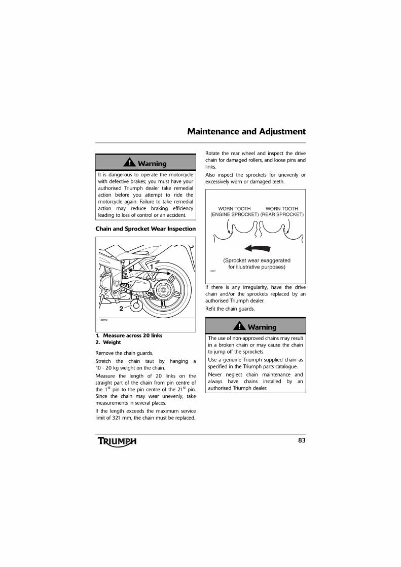
83
Maintenance and Adjustment
Chain and Sprocket Wear Inspection
1. Measure across 20 links2. Weight
Remove the chain guards.
Stretch the chain taut by hanging a10 - 20 kg weight on the chain.
Measure the length of 20 links on thestraight part of the chain from pin centre ofthe 1st pin to the pin centre of the 21st pin.Since the chain may wear unevenly, takemeasurements in several places.
If the length exceeds the maximum servicelimit of 321 mm, the chain must be replaced.
Rotate the rear wheel and inspect the drivechain for damaged rollers, and loose pins andlinks.
Also inspect the sprockets for unevenly orexcessively worn or damaged teeth.
If there is any irregularity, have the drivechain and/or the sprockets replaced by anauthorised Triumph dealer.
Refit the chain guards.
WarningIt is dangerous to operate the motorcyclewith defective brakes; you must have yourauthorised Triumph dealer take remedialaction before you attempt to ride themotorcycle again. Failure to take remedialaction may reduce braking efficiencyleading to loss of control or an accident.
ccmw
2
WarningThe use of non-approved chains may resultin a broken chain or may cause the chainto jump off the sprockets.
Use a genuine Triumph supplied chain asspecified in the Triumph parts catalogue.
Never neglect chain maintenance andalways have chains installed by anauthorised Triumph dealer.
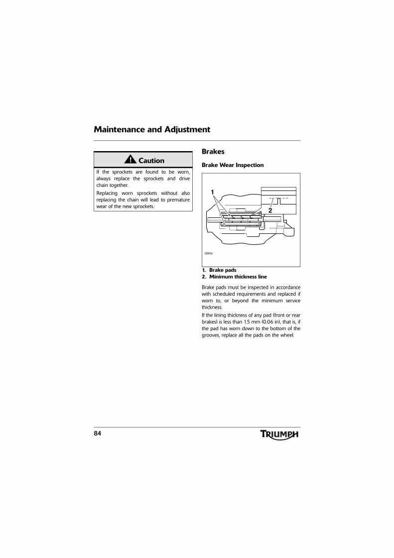
84
Maintenance and Adjustment
Brakes
Brake Wear Inspection
1. Brake pads2. Minimum thickness line
Brake pads must be inspected in accordancewith scheduled requirements and replaced ifworn to, or beyond the minimum servicethickness.
If the lining thickness of any pad (front or rearbrakes) is less than 1.5 mm (0.06 in), that is, ifthe pad has worn down to the bottom of thegrooves, replace all the pads on the wheel.
CautionIf the sprockets are found to be worn,always replace the sprockets and drivechain together.
Replacing worn sprockets without alsoreplacing the chain will lead to prematurewear of the new sprockets.
cbmz
1
2
85
Maintenance and Adjustment
Breaking-in New Brake Pads and DiscsAfter replacement brake discs and/or padshave been fitted to the motorcycle, werecommend a period of careful breaking-inthat will optimise the performance andlongevity of the discs and pads. Therecommended distance for breaking-in newpads and discs is 200 miles (300 km).
After fitting new brake discs and/or padsavoid extreme braking, ride with caution andallow for greater braking distances during thebreaking-in period.
Brake Pad Wear CompensationDisc and brake pad wear is automaticallycompensated for and has no effect on thebrake lever or pedal action. There are noparts that require adjustment on the frontand rear brakes.
WarningBrake pads must always be replaced as awheel set. At the front, where two calipersare fitted on the same wheel, replace allthe brake pads in both calipers.
Replacing individual pads will reducebraking efficiency and may cause anaccident.
After replacement brake pads have beenfitted, ride with extreme caution until thenew pads have 'broken in'.
WarningIf the brake lever or pedal feels soft when itis applied, or if the lever/pedal travelbecomes excessive, there may be air in thebrake pipes and hoses or the brakes maybe defective.
It is dangerous to operate the motorcycleunder such conditions and your authorisedTriumph dealer must rectify the faultbefore riding.
Riding with defective brakes may lead toloss of motorcycle control and an accident.
86
Maintenance and Adjustment
Disc Brake FluidInspect the level of brake fluid in bothreservoirs and change the brake fluid inaccordance with scheduled maintenancerequirements. Use only DOT 4 fluid asrecommended in the Specification section.The brake fluid must also be changed if itbecomes, or is suspected of having becomecontaminated with moisture or any othercontaminants.
Note:
• On models fitted with ABS, aspecial tool is required to bleedthe braking system. Contact yourauthorised Triumph dealer whenthe brake fluid needs renewing orthe hydraulic system requiresmaintenance.
WarningBrake fluid is hygroscopic which means itwill absorb moisture from the air.
Any absorbed moisture will greatly reducethe boiling point of the brake fluid causinga reduction in braking efficiency.
Because of this, always replace brake fluidin accordance with scheduled maintenancerequirements.
Always use new brake fluid from a sealedcontainer and never use fluid from anunsealed container or from one which hasbeen previously opened.
Do not mix different brands or grades ofbrake fluid.
Check for fluid leakage around brakefittings, seals and joints and also check thebrake hoses for splits, deterioration anddamage.
Always rectify any faults before riding.
Failure to observe and act upon any ofthese items may cause a dangerous ridingcondition leading to loss of control and anaccident.
WarningIf the ABS is not functioning, the brakesystem will continue to function as astandard non-ABS braking system. In thissituation, braking too hard will cause thewheels to lock resulting in loss of controland an accident.
Reduce speed and do not continue to ridefor longer than is necessary with theindicator light illuminated. Contact anauthorised Triumph dealer as soon aspossible to have the fault checked andrectified.
WarningFailure to observe and act upon any ofthese items may cause a dangerous ridingcondition leading to loss of control and anaccident.
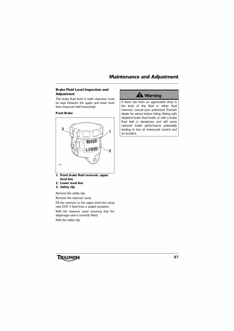
87
Maintenance and Adjustment
Brake Fluid Level Inspection and AdjustmentThe brake fluid level in both reservoirs mustbe kept between the upper and lower levellines (reservoir held horizontal).
Front Brake
1. Front brake fluid reservoir, upper level line
2. Lower level line3. Safety clip
Remove the safety clip.
Remove the reservoir cover.
Fill the reservoir to the upper level line usingnew DOT 4 fluid from a sealed container.
Refit the reservoir cover ensuring that thediaphragm seal is correctly fitted.
Refit the safety clip.
jajc
31
2
WarningIf there has been an appreciable drop inthe level of the fluid in either fluidreservoir, consult your authorised Triumphdealer for advice before riding. Riding withdepleted brake fluid levels, or with a brakefluid leak is dangerous and will causereduced brake performance potentiallyleading to loss of motorcycle control andan accident.
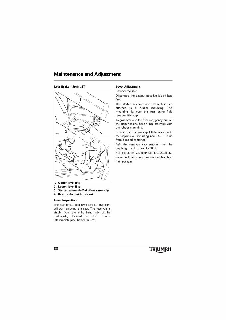
88
Maintenance and Adjustment
Rear Brake - Sprint ST
1. Upper level line2. Lower level line3. Starter solenoid/Main fuse assembly4. Rear brake fluid reservoir
Level InspectionThe rear brake fluid level can be inspectedwithout removing the seat. The reservoir isvisible from the right hand side of themotorcycle, forward of the exhaustintermediate pipe, below the seat.
Level AdjustmentRemove the seat.
Disconnect the battery, negative (black) leadfirst.
The starter solenoid and main fuse areattached to a rubber mounting. Thismounting fits over the rear brake fluidreservoir filler cap.
To gain access to the filler cap, gently pull offthe starter solenoid/main fuse assembly withthe rubber mounting.
Remove the reservoir cap. Fill the reservoir tothe upper level line using new DOT 4 fluidfrom a sealed container.
Refit the reservoir cap ensuring that thediaphragm seal is correctly fitted.
Refit the starter solenoid/main fuse assembly.
Reconnect the battery, positive (red) lead first.
Refit the seat.
ccns
1
2
4
3
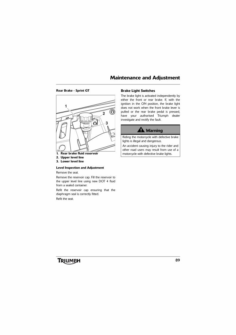
89
Maintenance and Adjustment
Rear Brake - Sprint GT
1. Rear brake fluid reservoir2. Upper level line3. Lower level line
Level Inspection and AdjustmentRemove the seat.
Remove the reservoir cap. Fill the reservoir tothe upper level line using new DOT 4 fluidfrom a sealed container.
Refit the reservoir cap ensuring that thediaphragm seal is correctly fitted.
Refit the seat.
Brake Light SwitchesThe brake light is activated independently byeither the front or rear brake. If, with theignition in the ON position, the brake lightdoes not work when the front brake lever ispulled or the rear brake pedal is pressed,have your authorised Triumph dealerinvestigate and rectify the fault.
cgbx
1
2
3
WarningRiding the motorcycle with defective brakelights is illegal and dangerous.
An accident causing injury to the rider andother road users may result from use of amotorcycle with defective brake lights.
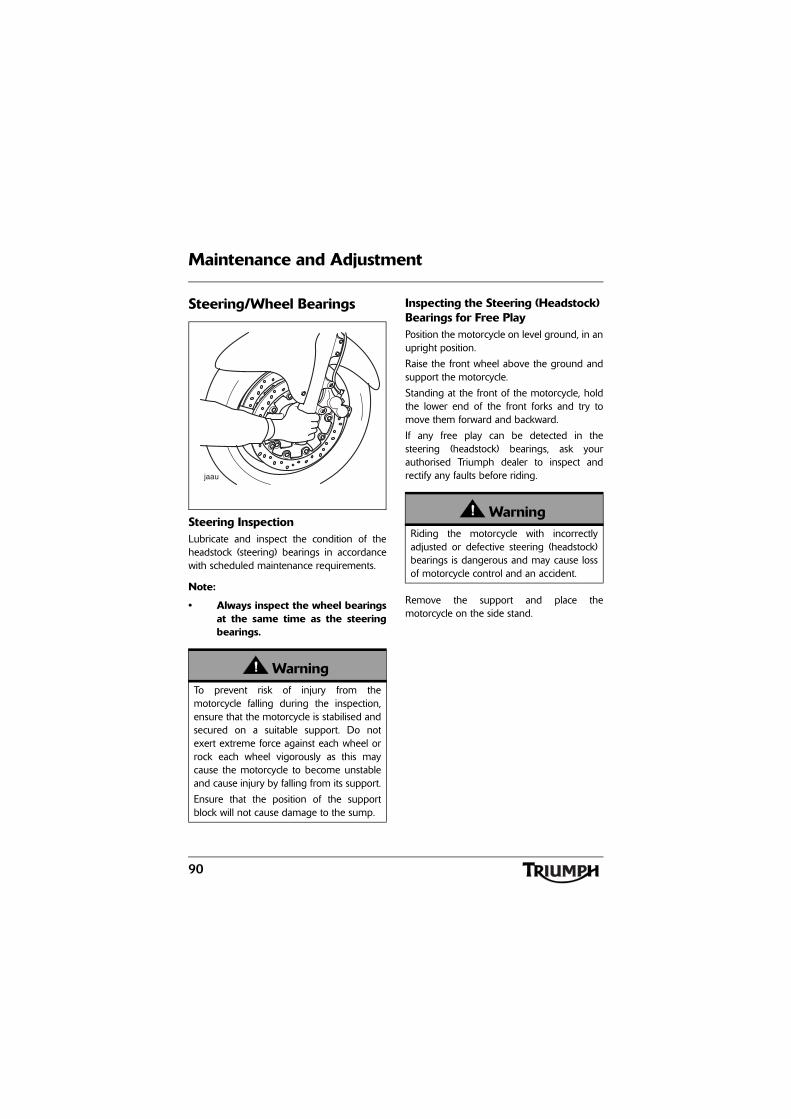
90
Maintenance and Adjustment
Steering/Wheel Bearings
Steering InspectionLubricate and inspect the condition of theheadstock (steering) bearings in accordancewith scheduled maintenance requirements.
Note:
• Always inspect the wheel bearingsat the same time as the steeringbearings.
Inspecting the Steering (Headstock) Bearings for Free PlayPosition the motorcycle on level ground, in anupright position.
Raise the front wheel above the ground andsupport the motorcycle.
Standing at the front of the motorcycle, holdthe lower end of the front forks and try tomove them forward and backward.
If any free play can be detected in thesteering (headstock) bearings, ask yourauthorised Triumph dealer to inspect andrectify any faults before riding.
Remove the support and place themotorcycle on the side stand.
WarningTo prevent risk of injury from themotorcycle falling during the inspection,ensure that the motorcycle is stabilised andsecured on a suitable support. Do notexert extreme force against each wheel orrock each wheel vigorously as this maycause the motorcycle to become unstableand cause injury by falling from its support.
Ensure that the position of the supportblock will not cause damage to the sump.
WarningRiding the motorcycle with incorrectlyadjusted or defective steering (headstock)bearings is dangerous and may cause lossof motorcycle control and an accident.
91
Maintenance and Adjustment
Wheel Bearings InspectionIf the wheel bearings in the front or rearwheel allow play in the wheel hub, are noisy,or if the wheel does not turn smoothly, haveyour authorised Triumph dealer inspect thewheel bearings.
The wheel bearings must be inspected at theintervals specified in the scheduledmaintenance chart.
Position the motorcycle on level ground, in anupright position.
Raise the front wheel above the ground andsupport the motorcycle.
Standing at the side of the motorcycle, gentlyrock the top of the front wheel from side toside.
If any free play can be detected, ask yourauthorised Triumph dealer to inspect andrectify any faults before riding.
Reposition the lifting device and repeat theprocedure for the rear wheel.
Remove the support and place themotorcycle on the side stand.
Front Suspension
Front Fork InspectionExamine each fork for any sign of damage,scratching of the slider surface, or for oilleaks.
If any damage or leakage is found, consult anauthorised Triumph dealer.
To check that the forks operate smoothly:
• Position the motorcycle on levelground.
• While holding the handlebars andapplying the front brake, pump theforks up and down several times.
• If roughness or excessive stiffness isdetected, consult your authorisedTriumph dealer.
• The suspension movement will beaffected by adjustment settings.
WarningOperation with worn or damaged front orrear wheel bearings is dangerous and maycause impaired handling and instabilityleading to an accident. If in doubt, have themotorcycle inspected by an authorisedTriumph dealer before riding.
WarningRiding the motorcycle with defective ordamaged suspension is dangerous andmay lead to loss of control and an accident.
WarningNever attempt to dismantle any part of thesuspension units, as all units containpressurised oil. Skin and eye damage canresult from contact with the pressurised oil.
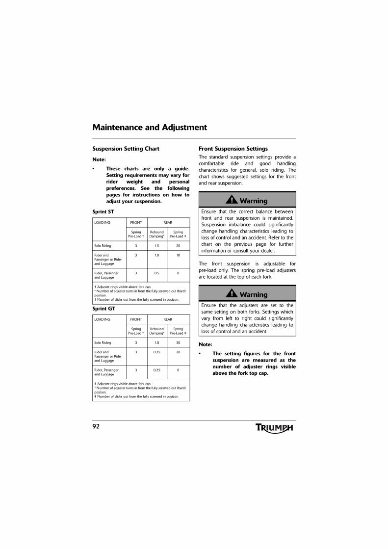
92
Maintenance and Adjustment
Suspension Setting Chart
Note:
• These charts are only a guide.Setting requirements may vary forrider weight and personalpreferences. See the followingpages for instructions on how toadjust your suspension.
Sprint ST
Sprint GT
Front Suspension SettingsThe standard suspension settings provide acomfortable ride and good handlingcharacteristics for general, solo riding. Thechart shows suggested settings for the frontand rear suspension.
The front suspension is adjustable forpre-load only. The spring pre-load adjustersare located at the top of each fork.
Note:
• The setting figures for the frontsuspension are measured as thenumber of adjuster rings visibleabove the fork top cap.
LOADING FRONT REAR
Spring Pre-Load †
Rebound Damping*
Spring Pre-Load ‡
Solo Riding 3 1.5 20
Rider and Passenger or Rider and Luggage
3 1.0 10
Rider, Passenger and Luggage
3 0.5 0
† Adjuster rings visible above fork cap.* Number of adjuster turns in from the fully screwed out (hard) position.‡ Number of clicks out from the fully screwed in position.
LOADING FRONT REAR
Spring Pre-Load †
Rebound Damping*
Spring Pre-Load ‡
Solo Riding 3 1.0 30
Rider and Passenger or Rider and Luggage
3 0.25 20
Rider, Passenger and Luggage
3 0.25 0
† Adjuster rings visible above fork cap.* Number of adjuster turns in from the fully screwed out (hard) position.‡ Number of clicks out from the fully screwed in position.
WarningEnsure that the correct balance betweenfront and rear suspension is maintained.Suspension imbalance could significantlychange handling characteristics leading toloss of control and an accident. Refer to thechart on the previous page for furtherinformation or consult your dealer.
WarningEnsure that the adjusters are set to thesame setting on both forks. Settings whichvary from left to right could significantlychange handling characteristics leading toloss of control and an accident.
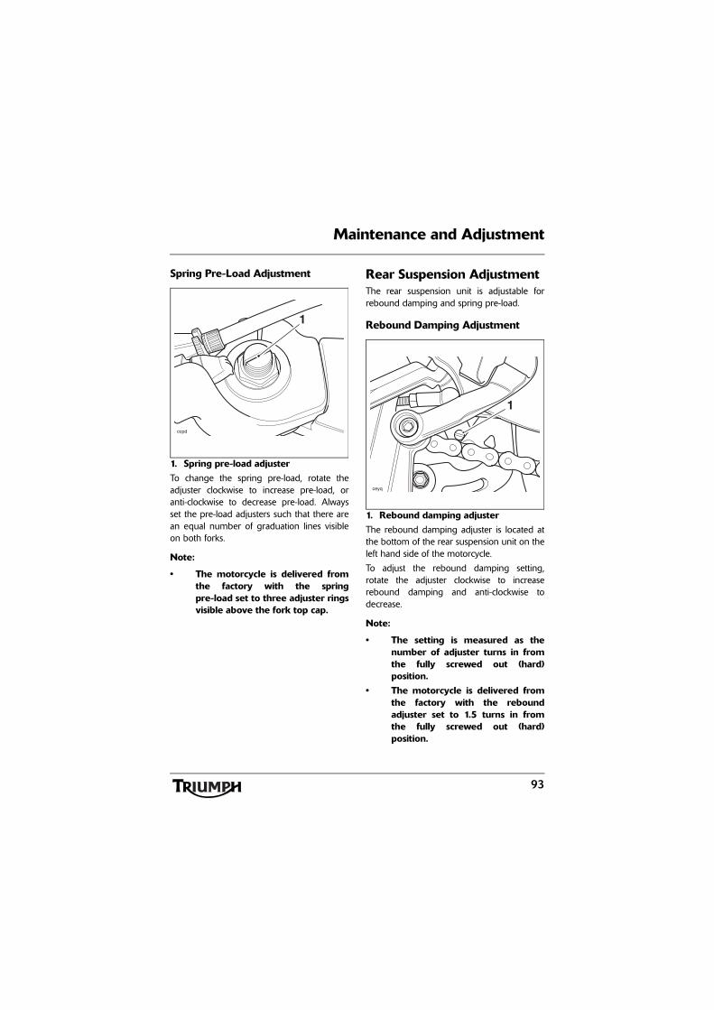
93
Maintenance and Adjustment
Spring Pre-Load Adjustment
1. Spring pre-load adjusterTo change the spring pre-load, rotate theadjuster clockwise to increase pre-load, oranti-clockwise to decrease pre-load. Alwaysset the pre-load adjusters such that there arean equal number of graduation lines visibleon both forks.
Note:
• The motorcycle is delivered fromthe factory with the springpre-load set to three adjuster ringsvisible above the fork top cap.
Rear Suspension AdjustmentThe rear suspension unit is adjustable forrebound damping and spring pre-load.
Rebound Damping Adjustment
1. Rebound damping adjusterThe rebound damping adjuster is located atthe bottom of the rear suspension unit on theleft hand side of the motorcycle.
To adjust the rebound damping setting,rotate the adjuster clockwise to increaserebound damping and anti-clockwise todecrease.
Note:
• The setting is measured as thenumber of adjuster turns in fromthe fully screwed out (hard)position.
• The motorcycle is delivered fromthe factory with the reboundadjuster set to 1.5 turns in fromthe fully screwed out (hard)position.
ccpd
1
1
ceyq
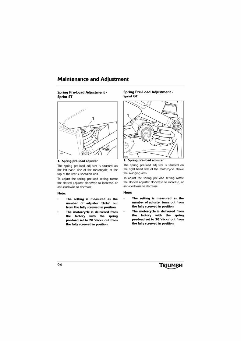
94
Maintenance and Adjustment
Spring Pre-Load Adjustment - Sprint ST
1. Spring pre-load adjusterThe spring pre-load adjuster is situated onthe left hand side of the motorcycle, at thetop of the rear suspension unit.
To adjust the spring pre-load setting rotatethe slotted adjuster clockwise to increase, oranti-clockwise to decrease.
Note:
• The setting is measured as thenumber of adjuster 'clicks' outfrom the fully screwed in position.
• The motorcycle is delivered fromthe factory with the springpre-load set to 20 'clicks' out fromthe fully screwed in position.
Spring Pre-Load Adjustment - Sprint GT
1. Spring pre-load adjusterThe spring pre-load adjuster is situated onthe right hand side of the motorcycle, abovethe swinging arm.
To adjust the spring pre-load setting rotatethe slotted adjuster clockwise to increase, oranti-clockwise to decrease.
Note:
• The setting is measured as thenumber of adjuster turns out fromthe fully screwed in position.
• The motorcycle is delivered fromthe factory with the springpre-load set to 30 'clicks' out fromthe fully screwed in position.
ccnt
1
cgdq
1
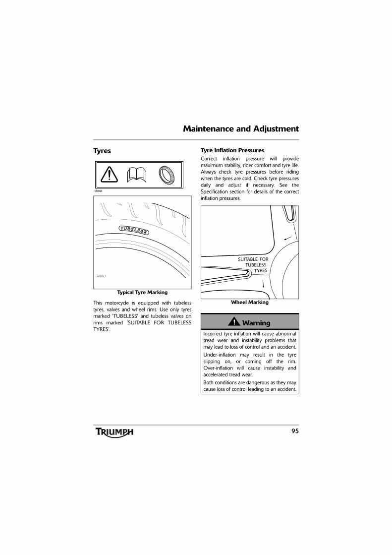
95
Maintenance and Adjustment
Tyres
Typical Tyre Marking
This motorcycle is equipped with tubelesstyres, valves and wheel rims. Use only tyresmarked 'TUBELESS' and tubeless valves onrims marked 'SUITABLE FOR TUBELESSTYRES'.
Tyre Inflation PressuresCorrect inflation pressure will providemaximum stability, rider comfort and tyre life.Always check tyre pressures before ridingwhen the tyres are cold. Check tyre pressuresdaily and adjust if necessary. See theSpecification section for details of the correctinflation pressures.
Wheel Marking
cboa
ccom_1
WarningIncorrect tyre inflation will cause abnormaltread wear and instability problems thatmay lead to loss of control and an accident.
Under-inflation may result in the tyreslipping on, or coming off the rim.Over-inflation will cause instability andaccelerated tread wear.
Both conditions are dangerous as they maycause loss of control leading to an accident.
SUITABLE FORTUBELESS
TYRES
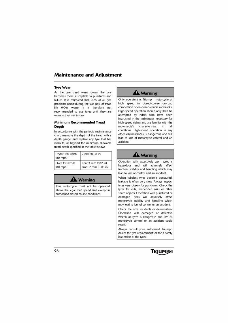
96
Maintenance and Adjustment
Tyre WearAs the tyre tread wears down, the tyrebecomes more susceptible to punctures andfailure. It is estimated that 90% of all tyreproblems occur during the last 10% of treadlife (90% worn). It is therefore notrecommended to use tyres until they areworn to their minimum.
Minimum Recommended Tread DepthIn accordance with the periodic maintenancechart, measure the depth of the tread with adepth gauge, and replace any tyre that hasworn to, or beyond the minimum allowabletread depth specified in the table below:
Under 130 km/h (80 mph)
2 mm (0.08 in)
Over 130 km/h (80 mph)
Rear 3 mm (0.12 in)Front 2 mm (0.08 in)
WarningThis motorcycle must not be operatedabove the legal road speed limit except inauthorised closed-course conditions.
WarningOnly operate this Triumph motorcycle athigh speed in closed-course on-roadcompetition or on closed-course racetracks.High-speed operation should only then beattempted by riders who have beeninstructed in the techniques necessary forhigh-speed riding and are familiar with themotorcycle's characteristics in allconditions. High-speed operation in anyother circumstances is dangerous and willlead to loss of motorcycle control and anaccident.
WarningOperation with excessively worn tyres ishazardous and will adversely affecttraction, stability and handling which maylead to loss of control and an accident.
When tubeless tyres become punctured,leakage is often very slow. Always inspecttyres very closely for punctures. Check thetyres for cuts, embedded nails or othersharp objects. Operation with punctured ordamaged tyres will adversely affectmotorcycle stability and handling whichmay lead to loss of control or an accident.
Check the rims for dents or deformation.Operation with damaged or defectivewheels or tyres is dangerous and loss ofmotorcycle control or an accident couldresult.
Always consult your authorised Triumphdealer for tyre replacement, or for a safetyinspection of the tyres.
97
Maintenance and Adjustment
Tyre ReplacementAll Triumph motorcycles are carefully andextensively tested in a range of ridingconditions to ensure that the most effectivetyre combinations are approved for use oneach model. It is essential that approved tyres,fitted in approved combinations, are usedwhen purchasing replacement tyres. The useof non-approved tyres, or approved tyres innon-approved combinations, may lead tomotorcycle instability and an accident. Onmodels fitted with ABS, different wheelspeeds, caused by fitting non-approved tyrescan affect the function of the ABS computer.
See the Specification section for details ofapproved tyre combinations. Always havetyres fitted and balanced by your authorisedTriumph dealer who has the necessarytraining and skills to ensure safe, effectivefitment.
WarningOn models fitted with ABS, the ABScomputer operates by comparing therelative speed of the front and rear wheels.Use of non-recommended tyres can affectwheel speed and cause the ABS functionnot to operate, potentially leading to loss ofcontrol and an accident in conditionswhere the ABS would normally function.
WarningIf a tyre sustains a puncture, the tyre mustbe replaced. Failure to replace a puncturedtyre, or operation with a repaired tyre canlead to instability, loss of control or anaccident.
WarningDo not install tube-type tyres on tubelessrims. The bead will not seat and the tyrescould slip on the rims, causing rapid tyredeflation that may result in a loss of vehiclecontrol and an accident. Never install aninner tube inside a tubeless tyre. This willcause friction inside the tyre and theresulting heat build-up may cause the tubeto burst resulting in rapid tyre deflation,loss of vehicle control and an accident.
WarningIf tyre damage is suspected, such as afterstriking the kerb, ask your authorisedTriumph dealer to inspect the tyre bothinternally and externally. Remember, tyredamage may not always be visible fromthe outside. Operation of the motorcyclewith damaged tyres could lead to loss ofcontrol and an accident.
98
Maintenance and Adjustment
WarningWhen replacement tyres are required,consult your authorised Triumph dealerwho will arrange for the tyres to beselected, in a correct combination, from theapproved list and fitted according to thetyre manufacturer's instructions.
When tyres are replaced, allow time for thetyres to seat to the rim (approximately24 hours). During this seating period, ridecautiously as an incorrectly seated tyrecould cause loss of control or an accident.
Initially, the new tyres will not produce thesame handling characteristics as the worntyres and the rider must allow adequateriding distance (approximately 100 miles)to become accustomed to the newhandling characteristics.
24 hours after fitting, the tyre pressuresmust be checked and adjusted, and thetyres examined for correct seating.Rectification must be carried out asnecessary.
The same checks and adjustments mustalso be carried out when 100 miles havebeen travelled after fitting.
WarningUse of a motorcycle with incorrectly seatedtyres, incorrectly adjusted tyre pressures, orwhen not accustomed to its handlingcharacteristics may lead to loss of controland an accident.
WarningTyres that have been used on a rollingroad dynamometer may becomedamaged. In some cases, the damage maynot be visible on the external surface of thetyre. Tyres must be replaced after such useas continued use of a damaged tyre maylead to instability, loss of control and anaccident.
WarningAccurate wheel balance is necessary forsafe, stable handling of the motorcycle. Donot remove or change any wheel balanceweights. Incorrect wheel balance maycause instability leading to loss of controland an accident.
When wheel balancing is required, such asafter tyre replacement, see your authorisedTriumph dealer.
Only use self-adhesive weights. Clip-onweights may damage the wheel and tyreresulting in tyre deflation, loss of controland an accident.
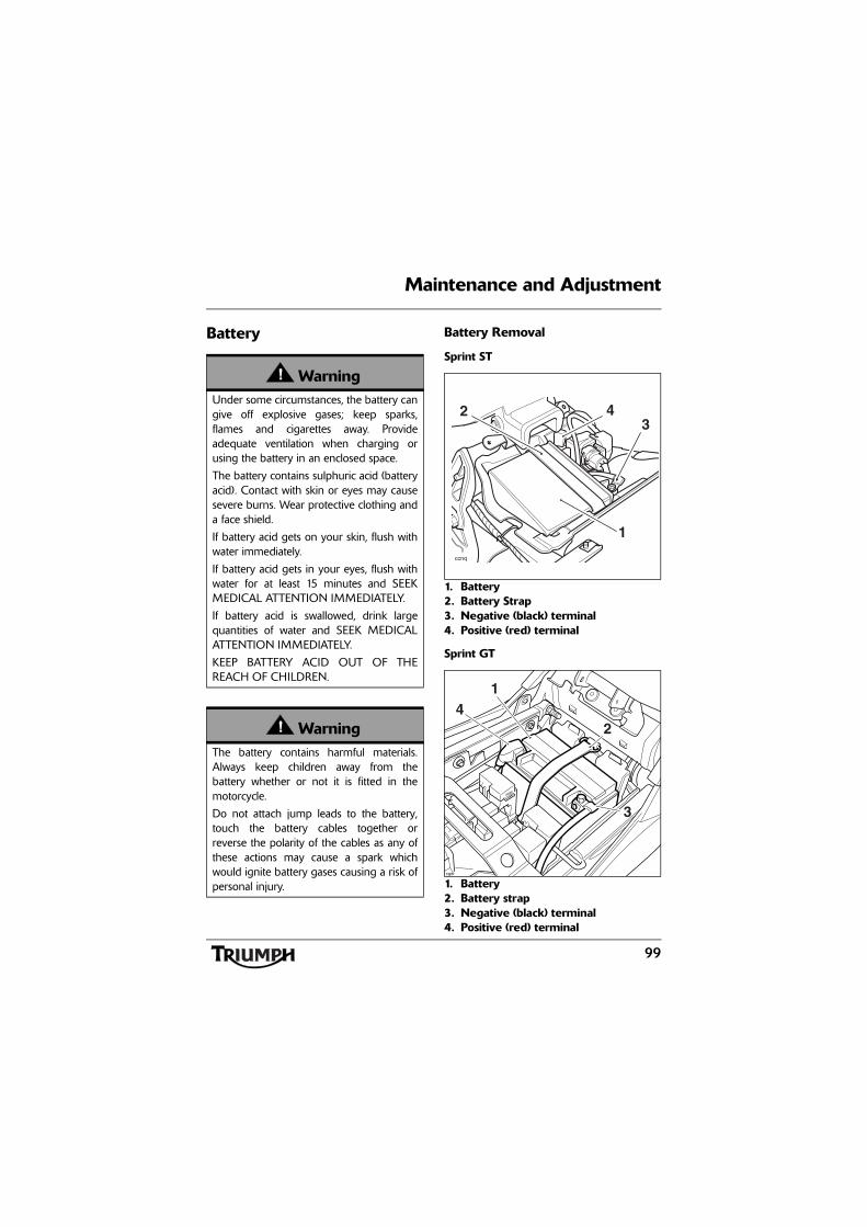
99
Maintenance and Adjustment
Battery Battery Removal
Sprint ST
1. Battery2. Battery Strap3. Negative (black) terminal4. Positive (red) terminal
Sprint GT
1. Battery2. Battery strap3. Negative (black) terminal4. Positive (red) terminal
WarningUnder some circumstances, the battery cangive off explosive gases; keep sparks,flames and cigarettes away. Provideadequate ventilation when charging orusing the battery in an enclosed space.
The battery contains sulphuric acid (batteryacid). Contact with skin or eyes may causesevere burns. Wear protective clothing anda face shield.
If battery acid gets on your skin, flush withwater immediately.
If battery acid gets in your eyes, flush withwater for at least 15 minutes and SEEKMEDICAL ATTENTION IMMEDIATELY.
If battery acid is swallowed, drink largequantities of water and SEEK MEDICALATTENTION IMMEDIATELY.
KEEP BATTERY ACID OUT OF THEREACH OF CHILDREN.
WarningThe battery contains harmful materials.Always keep children away from thebattery whether or not it is fitted in themotorcycle.
Do not attach jump leads to the battery,touch the battery cables together orreverse the polarity of the cables as any ofthese actions may cause a spark whichwould ignite battery gases causing a risk ofpersonal injury.
ccnq
1
342
41
2
cgdr
3
100
Maintenance and Adjustment
Remove the seat.
Remove the battery strap.
Disconnect the battery leads, negative (black)lead first.
Take the battery out of the case.
Battery DisposalShould the battery ever require replacement,the original battery must be handed to arecycling agent who will ensure that thedangerous substances from which the batteryis manufactured do not pollute theenvironment.
Battery MaintenanceClean the battery using a clean, dry cloth. Besure that the cable connections are clean.
The battery is a sealed type and does notrequire any maintenance other than checkingthe Voltage and routine recharging whenrequired, such as during storage.
It is not possible to adjust the battery acidlevel in the battery; the sealing strip must notbe removed.
Battery Discharge
WarningEnsure that the battery terminals do nottouch the motorcycle frame as this maycause a short circuit or spark, which wouldignite battery gases causing a risk ofpersonal injury.
WarningThe battery acid is corrosive and poisonousand will cause damage to unprotectedskin. Never swallow battery acid or allow itto come into contact with the skin. Toprevent injury, always wear eye and skinprotection when handling the battery.
CautionThe charge level in the battery must bemaintained to maximise battery life.
Failure to maintain the battery charge levelcould cause serious internal damage to thebattery.
101
Maintenance and Adjustment
Under normal conditions, the motorcyclecharging system will keep the battery fullycharged. However, if the motorcycle isunused, the battery will gradually dischargedue to a normal process called self discharge;the clock, engine control module (ECM)memory, high ambient temperatures, or theaddition of electrical security systems or otherelectrical accessories will all increase this rateof battery discharge. Disconnecting thebattery from the motorcycle during storagewill reduce the rate of discharge.
Battery Discharge During Storage and Infrequent Use of the MotorcycleDuring storage or infrequent use of themotorcycle, inspect the battery Voltageweekly using a digital multimeter. Follow themanufacturer's instructions supplied with themeter.
Should the battery Voltage fall below12.7 Volts, the battery should be charged(see page 101).
Allowing a battery to discharge or leaving itdischarged for even a short period of timecauses sulphation of the lead plates.Sulphation is a normal part of the chemicalreaction inside the battery, however over timethe sulphate can crystallise on the platesmaking recovery difficult or impossible. Thispermanent damage is not covered by themotorcycle warranty, as it is not due to amanufacturing defect.
Keeping the battery fully charged reduces thelikelihood of it freezing in cold conditions.Allowing a battery to freeze will cause seriousinternal damage to the battery.
Battery ChargingFor help with selecting a battery charger,checking the battery Voltage or batterycharging, contact your local authorisedTriumph dealer.
Should the battery Voltage fall below12.7 Volts, the battery should be chargedusing a Triumph approved battery charger.Always remove the battery from themotorcycle and follow the instructionssupplied with the battery charger.
WarningThe battery gives off explosive gases; keepsparks, flames and cigarettes away. Provideadequate ventilation when charging orusing the battery in an enclosed space.
The battery contains sulphuric acid (batteryacid). Contact with skin or eyes may causesevere burns. Wear protective clothing anda face shield.
If battery acid gets on your skin, flush withwater immediately.
If battery acid gets in your eyes, flush withwater for at least 15 minutes and SEEKMEDICAL ATTENTION IMMEDIATELY.
If battery acid is swallowed, drink largequantities of water and SEEK MEDICALATTENTION IMMEDIATELY.
KEEP BATTERY ACID OUT OF THEREACH OF CHILDREN.
CautionDo not use an automotive quick charger asit may overcharge and damage the battery.
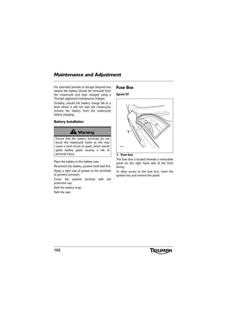
102
Maintenance and Adjustment
For extended periods of storage (beyond twoweeks) the battery should be removed fromthe motorcycle and kept charged using aTriumph approved maintenance charger.
Similarly, should the battery charge fall to alevel where it will not start the motorcycle,remove the battery from the motorcyclebefore charging.
Battery Installation
Place the battery in the battery case.
Reconnect the battery, positive (red) lead first.
Apply a light coat of grease to the terminalsto prevent corrosion.
Cover the positive terminal with theprotective cap.
Refit the battery strap.
Refit the seat.
Fuse Box
Sprint ST
1. Fuse boxThe fuse box is located beneath a removablepanel on the right hand side of the frontfairing.
To allow access to the fuse box, insert theignition key and remove the panel.
WarningEnsure that the battery terminals do nottouch the motorcycle frame as this maycause a short circuit or spark, which wouldignite battery gases causing a risk ofpersonal injury.
ccnp
1
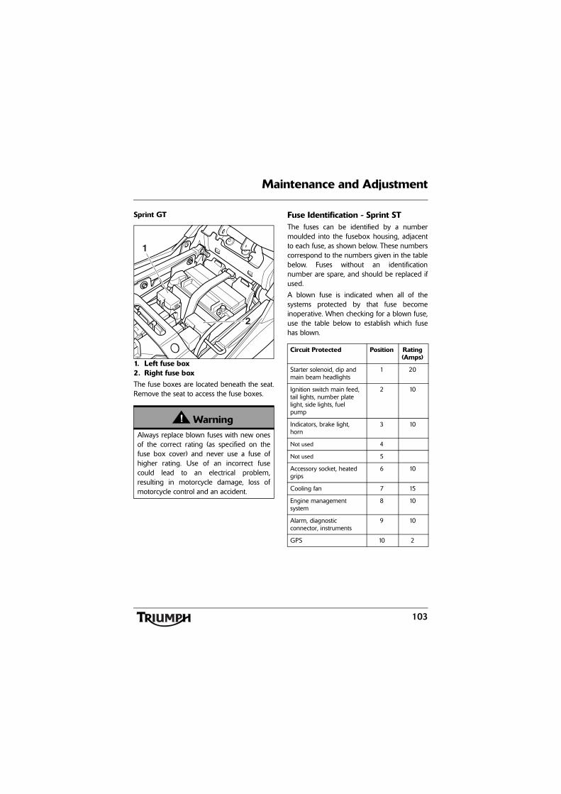
103
Maintenance and Adjustment
Sprint GT
1. Left fuse box2. Right fuse boxThe fuse boxes are located beneath the seat.Remove the seat to access the fuse boxes.
Fuse Identification - Sprint STThe fuses can be identified by a numbermoulded into the fusebox housing, adjacentto each fuse, as shown below. These numberscorrespond to the numbers given in the tablebelow. Fuses without an identificationnumber are spare, and should be replaced ifused.
A blown fuse is indicated when all of thesystems protected by that fuse becomeinoperative. When checking for a blown fuse,use the table below to establish which fusehas blown.
WarningAlways replace blown fuses with new onesof the correct rating (as specified on thefuse box cover) and never use a fuse ofhigher rating. Use of an incorrect fusecould lead to an electrical problem,resulting in motorcycle damage, loss ofmotorcycle control and an accident.
1
cgdr
2
Circuit Protected Position Rating (Amps)
Starter solenoid, dip and main beam headlights
1 20
Ignition switch main feed, tail lights, number plate light, side lights, fuel pump
2 10
Indicators, brake light, horn
3 10
Not used 4
Not used 5
Accessory socket, heated grips
6 10
Cooling fan 7 15
Engine management system
8 10
Alarm, diagnostic connector, instruments
9 10
GPS 10 2
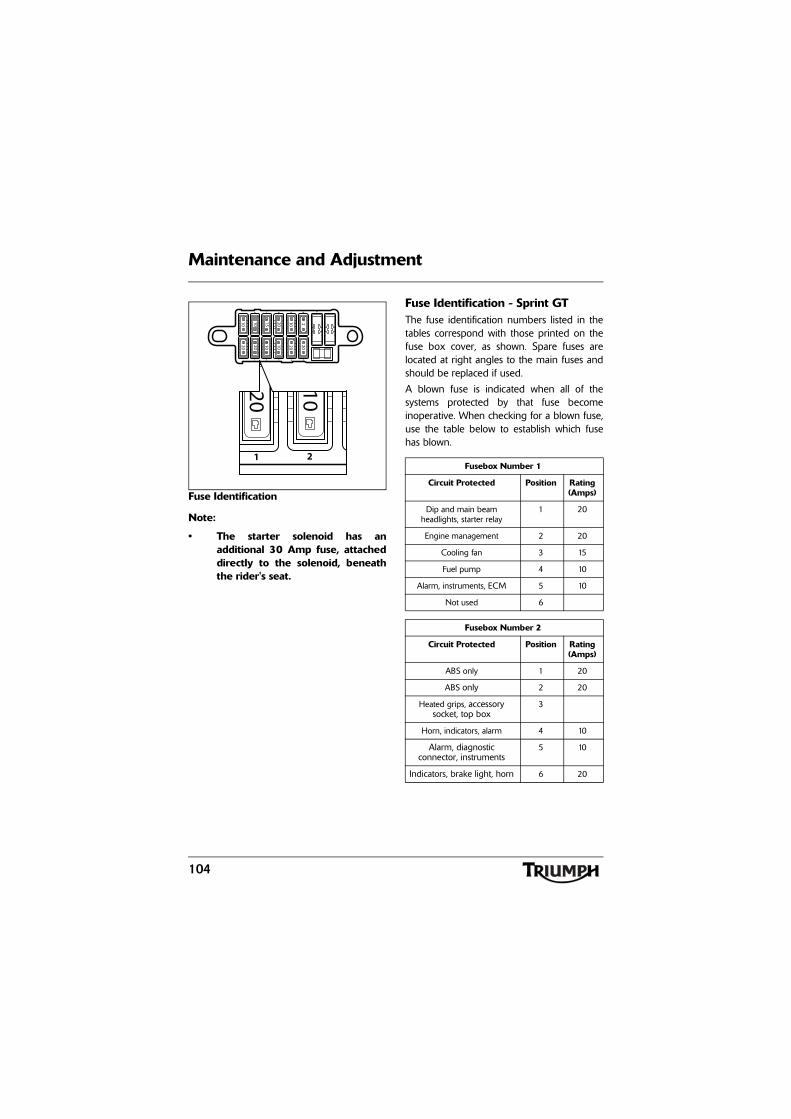
104
Maintenance and Adjustment
Fuse Identification
Note:
• The starter solenoid has anadditional 30 Amp fuse, attacheddirectly to the solenoid, beneaththe rider's seat.
Fuse Identification - Sprint GTThe fuse identification numbers listed in thetables correspond with those printed on thefuse box cover, as shown. Spare fuses arelocated at right angles to the main fuses andshould be replaced if used.
A blown fuse is indicated when all of thesystems protected by that fuse becomeinoperative. When checking for a blown fuse,use the table below to establish which fusehas blown.
22020
10102010 102015
1 2 3 4 5
6 7 8 9 10 11
1020
101 2
20
Fusebox Number 1
Circuit Protected Position Rating (Amps)
Dip and main beam headlights, starter relay
1 20
Engine management 2 20
Cooling fan 3 15
Fuel pump 4 10
Alarm, instruments, ECM 5 10
Not used 6
Fusebox Number 2
Circuit Protected Position Rating (Amps)
ABS only 1 20
ABS only 2 20
Heated grips, accessory socket, top box
3
Horn, indicators, alarm 4 10
Alarm, diagnostic connector, instruments
5 10
Indicators, brake light, horn 6 20
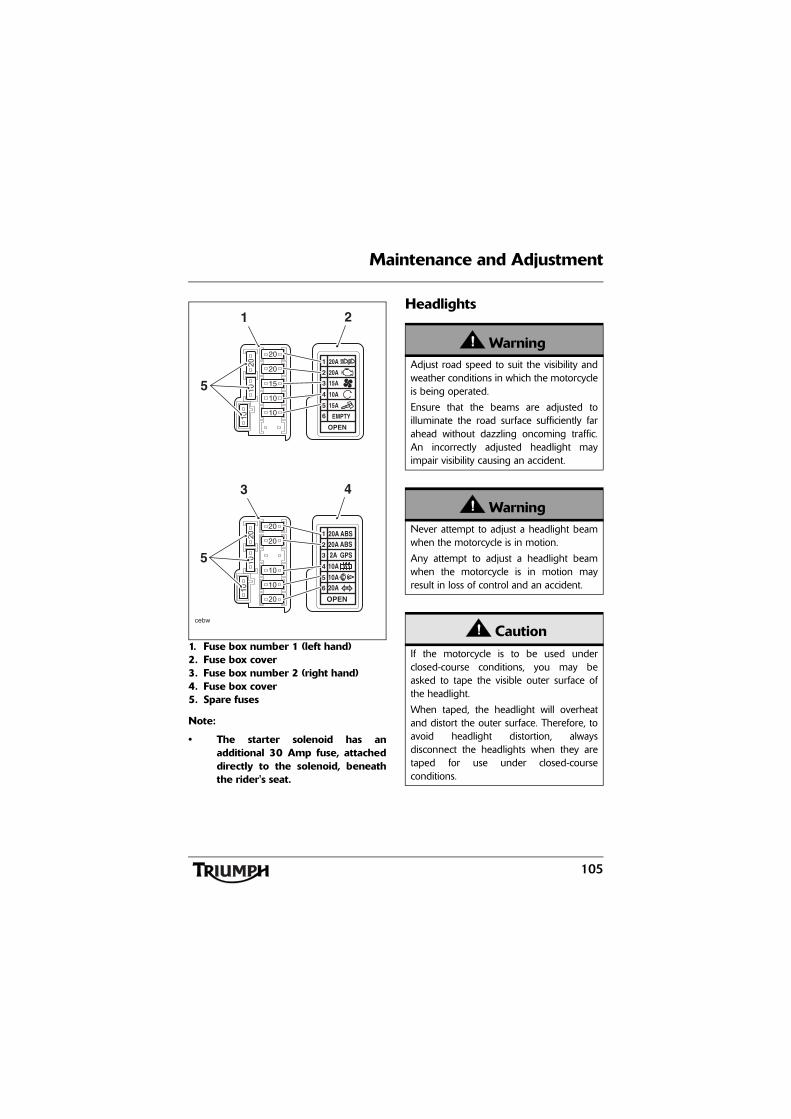
105
Maintenance and Adjustment
1. Fuse box number 1 (left hand)2. Fuse box cover3. Fuse box number 2 (right hand)4. Fuse box cover5. Spare fuses
Note:
• The starter solenoid has anadditional 30 Amp fuse, attacheddirectly to the solenoid, beneaththe rider's seat.
Headlights
20
10
10
15
1010
20
20
EMPTY6
OPEN
15A5
10A4
15A3
20A2
20A1
1 2
5
20
20
10
10
1010
20
20
20A6
OPEN
10A5
10A4
2A3
20A2
20A1
3 4
5
cebw
ABSABSGPS
WarningAdjust road speed to suit the visibility andweather conditions in which the motorcycleis being operated.
Ensure that the beams are adjusted toilluminate the road surface sufficiently farahead without dazzling oncoming traffic.An incorrectly adjusted headlight mayimpair visibility causing an accident.
WarningNever attempt to adjust a headlight beamwhen the motorcycle is in motion.
Any attempt to adjust a headlight beamwhen the motorcycle is in motion mayresult in loss of control and an accident.
CautionIf the motorcycle is to be used underclosed-course conditions, you may beasked to tape the visible outer surface ofthe headlight.
When taped, the headlight will overheatand distort the outer surface. Therefore, toavoid headlight distortion, alwaysdisconnect the headlights when they aretaped for use under closed-courseconditions.
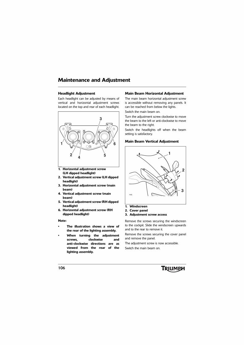
106
Maintenance and Adjustment
Headlight AdjustmentEach headlight can be adjusted by means ofvertical and horizontal adjustment screwslocated on the top and rear of each headlight.
1. Horizontal adjustment screw (LH dipped headlight)
2. Vertical adjustment screw (LH dipped headlight)
3. Horizontal adjustment screw (main beam)
4. Vertical adjustment screw (main beam)
5. Vertical adjustment screw (RH dipped headlight)
6. Horizontal adjustment screw (RH dipped headlight)
Note:
• The illustration shows a view ofthe rear of the lighting assembly.
• When turning the adjustmentscrews, clockwise andanti-clockwise directions are asviewed from the rear of thelighting assembly.
Main Beam Horizontal AdjustmentThe main beam horizontal adjustment screwis accessible without removing any panels. Itcan be reached from below the lights.
Switch the main beam on.
Turn the adjustment screw clockwise to movethe beam to the left or anti-clockwise to movethe beam to the right.
Switch the headlights off when the beamsetting is satisfactory.
Main Beam Vertical Adjustment
1. Windscreen2. Cover panel3. Adjustment screw access
Remove the screws securing the windscreento the cockpit. Slide the windscreen upwardsand to the rear to remove it.
Remove the screws securing the cover paneland remove the panel.
The adjustment screw is now accessible.
Switch the main beam on.
U
U
U
L
L
R
R
D
D
D
L
R
ccoy
1
2
3
4 5
6
ccpj
1
3
2
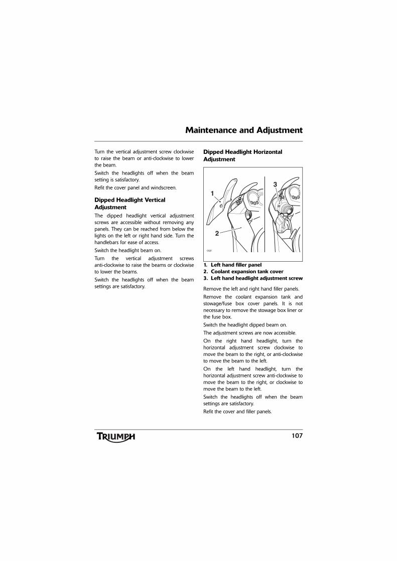
107
Maintenance and Adjustment
Turn the vertical adjustment screw clockwiseto raise the beam or anti-clockwise to lowerthe beam.
Switch the headlights off when the beamsetting is satisfactory.
Refit the cover panel and windscreen.
Dipped Headlight Vertical AdjustmentThe dipped headlight vertical adjustmentscrews are accessible without removing anypanels. They can be reached from below thelights on the left or right hand side. Turn thehandlebars for ease of access.
Switch the headlight beam on.
Turn the vertical adjustment screwsanti-clockwise to raise the beams or clockwiseto lower the beams.
Switch the headlights off when the beamsettings are satisfactory.
Dipped Headlight Horizontal Adjustment
1. Left hand filler panel2. Coolant expansion tank cover3. Left hand headlight adjustment screw
Remove the left and right hand filler panels.
Remove the coolant expansion tank andstowage/fuse box cover panels. It is notnecessary to remove the stowage box liner orthe fuse box.
Switch the headlight dipped beam on.
The adjustment screws are now accessible.
On the right hand headlight, turn thehorizontal adjustment screw clockwise tomove the beam to the right, or anti-clockwiseto move the beam to the left.
On the left hand headlight, turn thehorizontal adjustment screw anti-clockwise tomove the beam to the right, or clockwise tomove the beam to the left.
Switch the headlights off when the beamsettings are satisfactory.
Refit the cover and filler panels.
ccpi
1
2
3
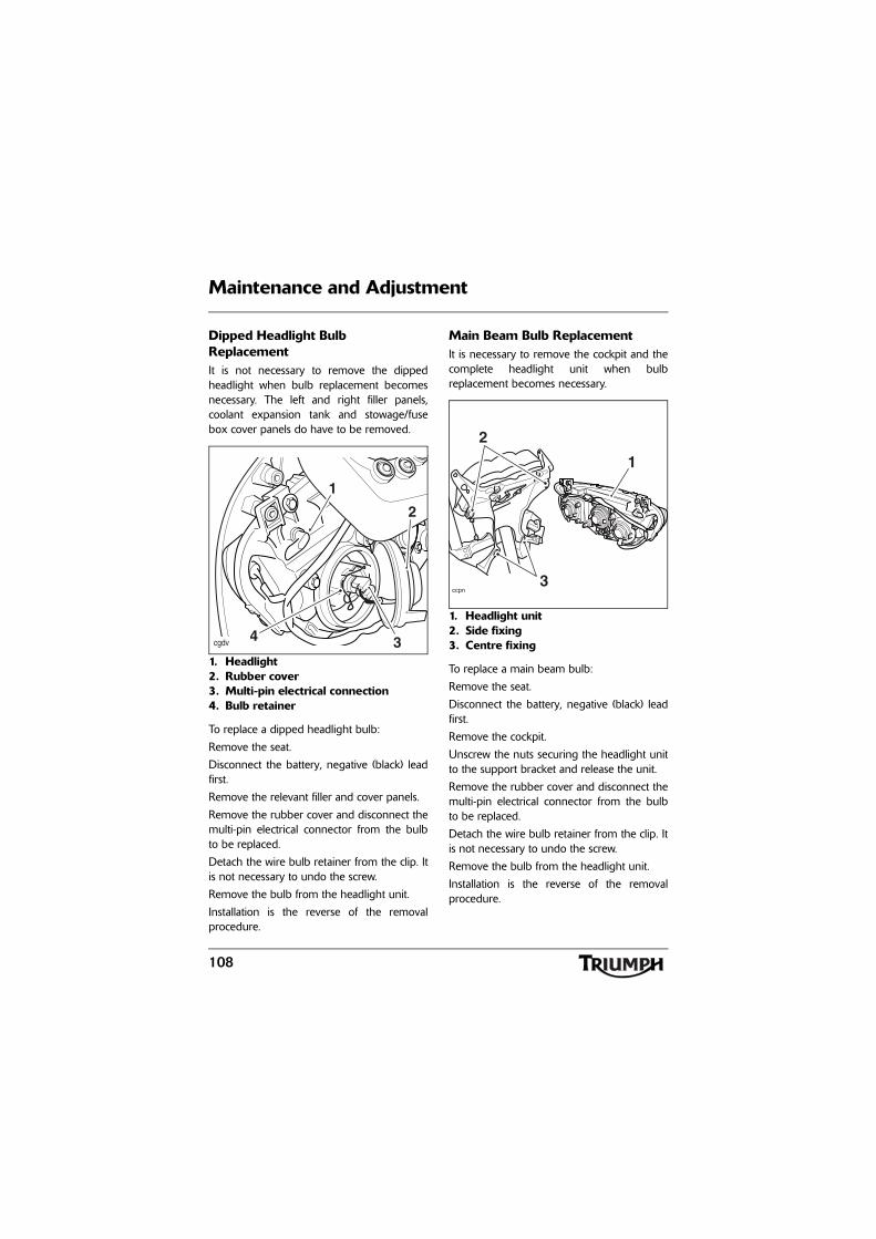
108
Maintenance and Adjustment
Dipped Headlight Bulb ReplacementIt is not necessary to remove the dippedheadlight when bulb replacement becomesnecessary. The left and right filler panels,coolant expansion tank and stowage/fusebox cover panels do have to be removed.
1. Headlight2. Rubber cover3. Multi-pin electrical connection4. Bulb retainer
To replace a dipped headlight bulb:
Remove the seat.
Disconnect the battery, negative (black) leadfirst.
Remove the relevant filler and cover panels.
Remove the rubber cover and disconnect themulti-pin electrical connector from the bulbto be replaced.
Detach the wire bulb retainer from the clip. Itis not necessary to undo the screw.
Remove the bulb from the headlight unit.
Installation is the reverse of the removalprocedure.
Main Beam Bulb ReplacementIt is necessary to remove the cockpit and thecomplete headlight unit when bulbreplacement becomes necessary.
1. Headlight unit2. Side fixing3. Centre fixing
To replace a main beam bulb:
Remove the seat.
Disconnect the battery, negative (black) leadfirst.
Remove the cockpit.
Unscrew the nuts securing the headlight unitto the support bracket and release the unit.
Remove the rubber cover and disconnect themulti-pin electrical connector from the bulbto be replaced.
Detach the wire bulb retainer from the clip. Itis not necessary to undo the screw.
Remove the bulb from the headlight unit.
Installation is the reverse of the removalprocedure.
cgdv
2
1
4 3
ccpn
1
2
3
109
Maintenance and Adjustment
Position Lamp Bulb ReplacementThe position lamps are fitted within theheadlight aperture.
Carefully remove the rubber bulb holderfrom the back of the position lamp anddetach the bulb.
Installation is the reverse of the removalprocedure.
Rear LightThe rear light unit is a sealed, maintenancefree LED unit.
WarningThe bulbs become hot during use. Alwaysallow sufficient time for the bulbs to coolbefore handling. Avoid touching the glasspart of the bulb. If the glass is touched orgets dirty, clean with alcohol before re-use.
CautionEnsure that the bulb holder is correctlyfitted to prevent water ingress.
WarningWhen reconnecting the battery, connectthe positive (red) lead first.
WarningDo not reconnect the battery until theassembly process has been completed.Premature battery reconnection couldresult in ignition of the battery gasescausing risk of injury.
WarningRiding the motorcycle with defective brakelights is illegal and dangerous. In the eventof failure of the LED unit, consult yourauthorised Triumph dealer.
An accident causing injury to the rider andother road users may result from use of amotorcycle with defective brake lights.
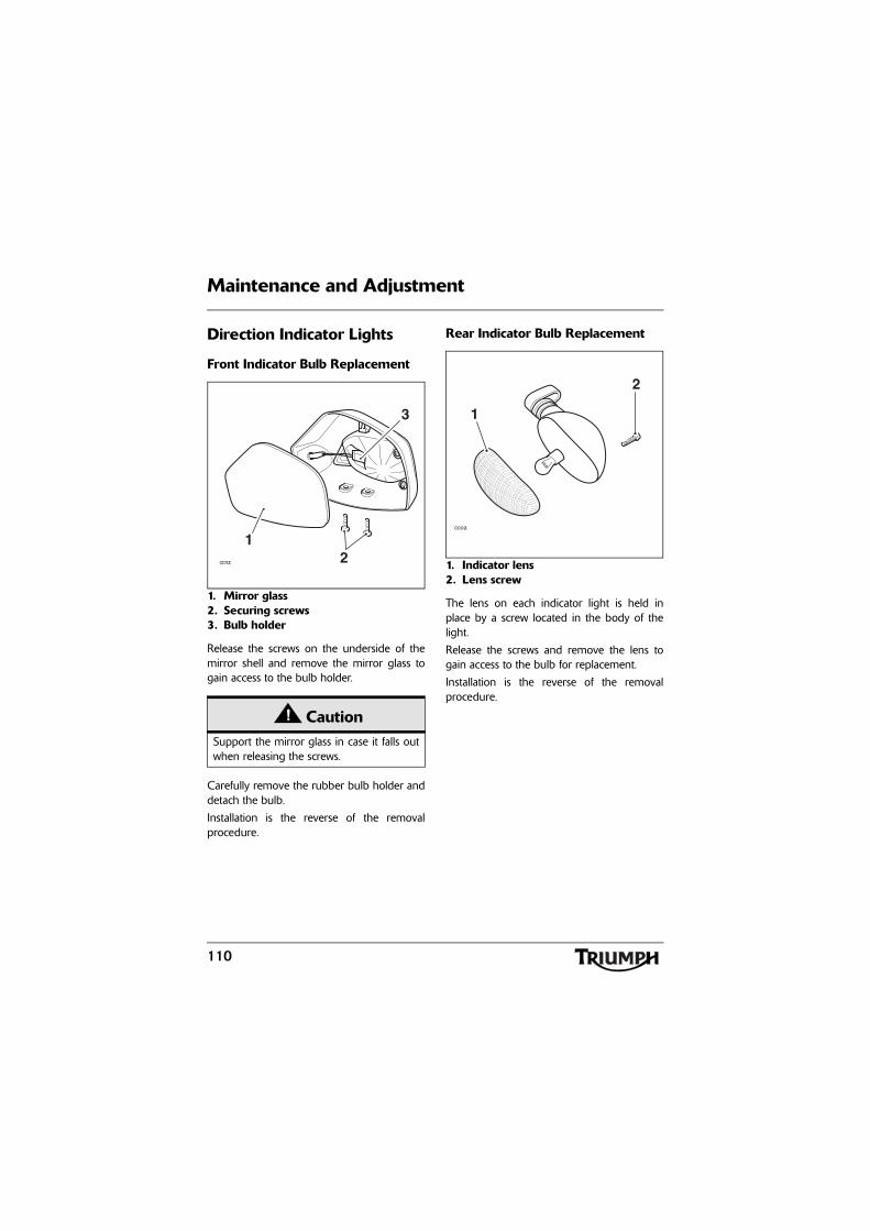
110
Maintenance and Adjustment
Direction Indicator Lights
Front Indicator Bulb Replacement
1. Mirror glass2. Securing screws3. Bulb holder
Release the screws on the underside of themirror shell and remove the mirror glass togain access to the bulb holder.
Carefully remove the rubber bulb holder anddetach the bulb.
Installation is the reverse of the removalprocedure.
Rear Indicator Bulb Replacement
1. Indicator lens2. Lens screw
The lens on each indicator light is held inplace by a screw located in the body of thelight.
Release the screws and remove the lens togain access to the bulb for replacement.
Installation is the reverse of the removalprocedure.
CautionSupport the mirror glass in case it falls outwhen releasing the screws.
ccnz
12
3
ccoa
1
2
111
Maintenance and Adjustment
Licence Plate Light
Bulb ReplacementCarefully remove the rubber bulb holderfrom the back of the licence plate light unitand remove the bulb.
Installation is the reverse of the removalprocedure.
Windscreen Cleaning
Clean the windscreen with a solution of mildsoap or detergent and lukewarm water. Aftercleaning, rinse well and then dry with a soft,lint free cloth.
If the transparency of the windscreen isreduced by scratches or oxidation whichcannot be removed, the windscreen must bereplaced.
CautionTo avoid cable damage, do not pull thebulb holder using the cables.
CautionEnsure that the bulb holder is correctlyfitted to prevent water ingress.
CautionProducts such as window cleaning fluids,insect remover, rain repellent, scouringcompounds, petrol or strong solvents suchas alcohol, acetone, carbon tetrachloride,etc. will damage the windscreen. Neverallow these products to contact thewindscreen.
112
Maintenance and Adjustment
CleaningFrequent, regular cleaning is an essential partof the maintenance of your motorcycle. Ifregularly cleaned, the appearance will bepreserved for many years. Cleaning with coldwater containing an automotive cleaner isessential at all times but particularly so afterexposure to sea breezes, sea water, dusty ormuddy roads and in winter when roads aretreated for ice and snow. Do not usehousehold detergent, as the use of suchproducts will lead to premature corrosion.Although, under the terms of yourmotorcycle warranty, cover is providedagainst the corrosion of certain items, theowner is expected to observe this reasonableadvice which will safeguard against corrosionand enhance the appearance of themotorcycle.
Preparation for WashingBefore washing, precautions must be takento keep water off the following places:Rear opening of the exhausts: Cover with aplastic bag secured with rubber bands.Clutch and brake levers, switch housings onthe handlebar: Cover with plastic bags.Ignition switch and steering lock: Cover thekeyhole with tape.Remove any items of jewellery such as rings,watches, zips or belt buckles, which mayscratch or otherwise damage painted orpolished surfaces.Use separate cleaning sponges or cleaningcloths for washing painted/polished surfacesand chassis areas. Chassis areas (such aswheels and under mudguards) will beexposed to more abrasive road grime anddust, which may then scratch painted orpolished surfaces, if the same sponge orcleaning cloths are used.
WarningNever attempt to clean the windscreenwhile the motorcycle is in motion asreleasing the handlebars may cause loss ofvehicle control and an accident.
Operation of the motorcycle with adamaged or scratched windscreen willreduce the rider's forward vision. Any suchreduction in forward vision is dangerousand may lead to an accident causing injuryor death.
CautionCorrosive chemicals such as battery acidwill damage the windscreen. Never allowcorrosive chemicals to contact thewindscreen.
113
Maintenance and Adjustment
Where to be CarefulAvoid spraying water with any great forcenear the following places:
• Instruments;
• Brake cylinders and brake calipers;
• Under the fuel tank;
• Drive chain;
• Headstock bearings;
• Wheel bearings and suspensionlinkage bearings.
Note:
• Use of soaps that contain highlevels of alkaline will leave aresidue on painted surfaces, andmay also cause water spotting.Always use a low alkaline soap toaid the cleaning process.
After WashingRemove the plastic bags and tape, and clearthe air intakes.
Lubricate the pivots, bolts and nuts.
Test the brakes before motorcycle operation.
Start the engine and run it for 5 minutes.Ensure adequate ventilation for the exhaustfumes.
Use a dry cloth to absorb water residue. Donot allow water to stand on the machine asthis will lead to corrosion.
Seat Care
To help maintain its appearance, clean theseat using a sponge or cleaning cloth withsoap and water.
CautionDo not spray any water at all under thecockpit area. The engine’s air intake ductsare located in this area, and any watersprayed in this area could enter the airboxand engine, causing damage to both items.
CautionUse of high-pressure spray washers is notrecommended. When using pressurewashers, water may be forced intobearings and other components causingpremature wear from corrosion and loss oflubrication.
WarningNever wax or lubricate the brake discs.Loss of braking power and an accidentcould result. Clean the disc with aproprietary brand of oil-free brake disccleaner.
CautionUse of chemicals or high-pressure spraywashers is not recommended for cleaningthe seat. When using chemicals or pressurewashers the seat cover may get damaged.
114
Maintenance and Adjustment
Unpainted Aluminium ItemsItems such as brake and clutch levers mustbe correctly cleaned to preserve theirappearance.
Use a proprietary brand of aluminiumcleaner which does not contain abrasive orcaustic elements.
Clean aluminium items regularly, in particularafter use in inclement weather, where thecomponents must be hand washed and driedeach time the machine is used.
Warranty claims due to inadequatemaintenance will not be allowed.
Cleaning of the Exhaust SystemAll parts of the exhaust system of yourmotorcycle must be cleaned regularly toavoid a deterioration of its appearance. Theseinstructions can be applied to chrome,brushed stainless steel and carbon fibrecomponents alike.
Note:
• The exhaust system must be coolbefore washing to prevent waterspotting.
WashingPrepare a mixture of cold water and mildautomotive cleaner. Do not use a highlyalkaline soap as commonly found atcommercial car washes because it leaves aresidue.
Wash the exhaust system with a soft cloth. Donot use an abrasive scouring pad or steelwool. They will damage the finish.
Rinse the exhaust system thoroughly.
Ensure no soap or water enters the exhausts.
DryingDry the exhaust system as far as possible witha soft cloth. Do not run the engine to dry thesystem or spotting will occur.
ProtectingWhen the exhaust system is dry, rub'Motorex 645 Clean and Protect' into thesurface.
It is recommended that regular protection beapplied to the system as this will both protectand enhance the system's appearance.
CautionThe use of products containing silicone willcause discolouration of the chrome andmust not be used. Similarly, the use ofabrasive cleaners and polishes will damagethe system and must not be used.
115
Storage
STORAGE
Preparation for StorageClean the entire vehicle thoroughly.
Fill the fuel tank with the correct grade ofunleaded fuel and add a fuel stabiliser (ifavailable), following the fuel stabilisermanufacturer's instructions.
Remove the spark plug from each cylinderand put several drops (5 ml) of engine oil intoeach cylinder. Cover the spark plug holeswith a piece of cloth or rag. With the enginestop switch in the RUN position, push thestarter button for a few seconds to coat thecylinder walls with oil. Install the spark plugs,tightening to 12 Nm.
Change the engine oil and filter (seepage 73).
Check and if necessary correct the tyrepressures (see page 120).
Set the motorcycle on a box or stand so thatboth wheels are raised off the ground. (If thiscannot be done, put boards under the frontand rear wheels to keep dampness awayfrom the tyres.)
Spray rust inhibiting oil (there are a host ofproducts on the market and your dealer willbe able to offer you local advice) on allunpainted metal surfaces to prevent rusting.Prevent oil from getting on rubber parts,brake discs or in the brake calipers.
Lubricate and if necessary adjust the drivechain (see page 81).
Make sure the cooling system is filled with a50% mixture of anti-freeze and distilledwater solution (see page 118).
Remove the battery, and store it where it willnot be exposed to direct sunlight, moisture,or freezing temperatures. During storage itshould be given a slow charge (one ampereor less) about once every two weeks(see page 100).
Store the motorcycle in a cool, dry area, awayfrom sunlight, and with a minimum dailytemperature variation.
Put a suitable porous cover over themotorcycle to keep dust and dirt fromcollecting on it. Avoid using plastic or similarnon-breathable, coated materials that restrictair flow and allow heat and moisture toaccumulate.
WarningPetrol is extremely flammable and can beexplosive under certain conditions. Turnthe ignition switch off. Do not smoke.Make sure the area is well ventilated andfree from any source of flame or sparks;this includes any appliance with a pilotlight.
116
Storage
Preparation after StorageInstall the battery (if removed) (seepage 102).
If the motorcycle has been stored for morethan four months, change the engine oil (seepage 73).
Check all the points listed in the Daily SafetyChecks section.
Before starting the engine, remove the sparkplugs from each cylinder.
Put the side stand down.
Crank the engine on the starter motor severaltimes until the oil pressure light goes out.
Replace the spark plugs, tightening to12 Nm, and start the engine.
Check and if necessary correct the tyrepressures (see page 120).
Check the brakes for correct operation.
Test ride the motorcycle at low speeds.
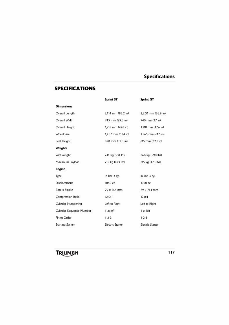
Specifications
117
SPECIFICATIONS
Sprint ST Sprint GT
Dimensions
Overall Length 2,114 mm (83.2 in) 2,260 mm (88.9 in)
Overall Width 745 mm (29.3 in) 940 mm (37 in)
Overall Height: 1,215 mm (47.8 in) 1,210 mm (47.6 in)
Wheelbase 1,457 mm (57.4 in) 1,565 mm (61.6 in)
Seat Height 820 mm (32.3 in) 815 mm (32.1 in)
Weights
Wet Weight 241 kg (531 lbs) 268 kg (590 lbs)
Maximum Payload 215 kg (473 lbs) 215 kg (473 lbs)
Engine
Type In-line 3 cyl. In-line 3 cyl.
Displacement 1050 cc 1050 cc
Bore x Stroke 79 x 71.4 mm 79 x 71.4 mm
Compression Ratio 12.0:1 12.0:1
Cylinder Numbering Left to Right Left to Right
Cylinder Sequence Number 1 at left 1 at left
Firing Order 1-2-3 1-2-3
Starting System Electric Starter Electric Starter
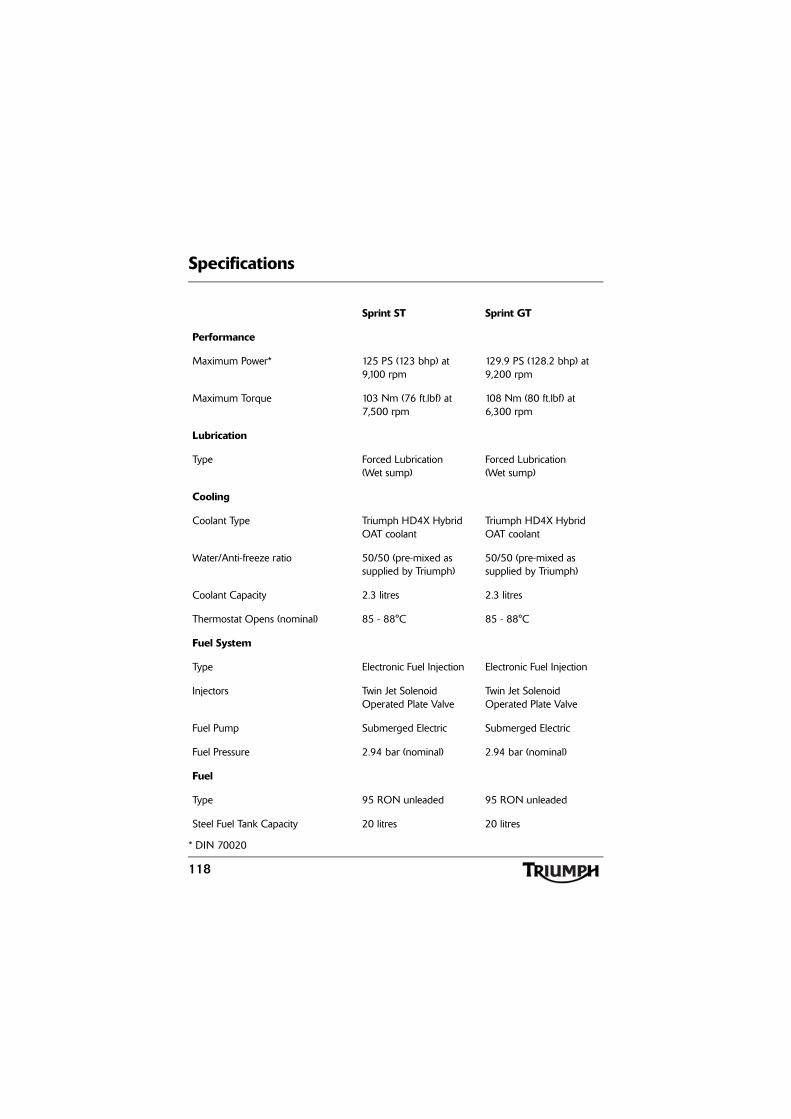
Specifications
118
* DIN 70020
Sprint ST Sprint GT
Performance
Maximum Power* 125 PS (123 bhp) at 9,100 rpm
129.9 PS (128.2 bhp) at 9,200 rpm
Maximum Torque 103 Nm (76 ft.lbf) at 7,500 rpm
108 Nm (80 ft.lbf) at 6,300 rpm
Lubrication
Type Forced Lubrication (Wet sump)
Forced Lubrication (Wet sump)
Cooling
Coolant Type Triumph HD4X Hybrid OAT coolant
Triumph HD4X Hybrid OAT coolant
Water/Anti-freeze ratio 50/50 (pre-mixed as supplied by Triumph)
50/50 (pre-mixed as supplied by Triumph)
Coolant Capacity 2.3 litres 2.3 litres
Thermostat Opens (nominal) 85 - 88°C 85 - 88°C
Fuel System
Type Electronic Fuel Injection Electronic Fuel Injection
Injectors Twin Jet Solenoid Operated Plate Valve
Twin Jet Solenoid Operated Plate Valve
Fuel Pump Submerged Electric Submerged Electric
Fuel Pressure 2.94 bar (nominal) 2.94 bar (nominal)
Fuel
Type 95 RON unleaded 95 RON unleaded
Steel Fuel Tank Capacity 20 litres 20 litres
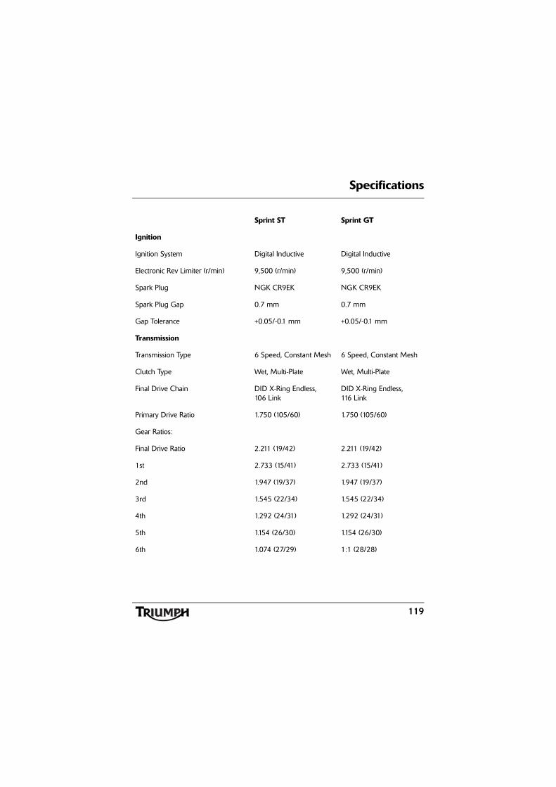
Specifications
119
Sprint ST Sprint GT
Ignition
Ignition System Digital Inductive Digital Inductive
Electronic Rev Limiter (r/min) 9,500 (r/min) 9,500 (r/min)
Spark Plug NGK CR9EK NGK CR9EK
Spark Plug Gap 0.7 mm 0.7 mm
Gap Tolerance +0.05/-0.1 mm +0.05/-0.1 mm
Transmission
Transmission Type 6 Speed, Constant Mesh 6 Speed, Constant Mesh
Clutch Type Wet, Multi-Plate Wet, Multi-Plate
Final Drive Chain DID X-Ring Endless, 106 Link
DID X-Ring Endless, 116 Link
Primary Drive Ratio 1.750 (105/60) 1.750 (105/60)
Gear Ratios:
Final Drive Ratio 2.211 (19/42) 2.211 (19/42)
1st 2.733 (15/41) 2.733 (15/41)
2nd 1.947 (19/37) 1.947 (19/37)
3rd 1.545 (22/34) 1.545 (22/34)
4th 1.292 (24/31) 1.292 (24/31)
5th 1.154 (26/30) 1.154 (26/30)
6th 1.074 (27/29) 1:1 (28/28)
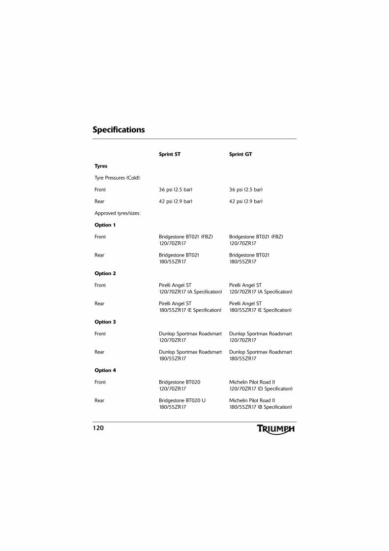
Specifications
120
Sprint ST Sprint GT
Tyres
Tyre Pressures (Cold):
Front 36 psi (2.5 bar) 36 psi (2.5 bar)
Rear 42 psi (2.9 bar) 42 psi (2.9 bar)
Approved tyres/sizes:
Option 1
Front Bridgestone BT021 (FBZ) 120/70ZR17
Bridgestone BT021 (FBZ) 120/70ZR17
Rear Bridgestone BT021180/55ZR17
Bridgestone BT021180/55ZR17
Option 2
Front Pirelli Angel ST 120/70ZR17 (A Specification)
Pirelli Angel ST 120/70ZR17 (A Specification)
Rear Pirelli Angel ST180/55ZR17 (E Specification)
Pirelli Angel ST180/55ZR17 (E Specification)
Option 3
Front Dunlop Sportmax Roadsmart 120/70ZR17
Dunlop Sportmax Roadsmart 120/70ZR17
Rear Dunlop Sportmax Roadsmart 180/55ZR17
Dunlop Sportmax Roadsmart 180/55ZR17
Option 4
Front Bridgestone BT020120/70ZR17
Michelin Pilot Road II120/70ZR17 (D Specification)
Rear Bridgestone BT020 U180/55ZR17
Michelin Pilot Road II180/55ZR17 (B Specification)
Specifications
121
WarningUse the recommended tyres ONLY in the combinations given. Do not mix tyres fromdifferent manufacturers or mix different specification tyres from the same manufacturer asthis may result in loss of motorcycle control and an accident.
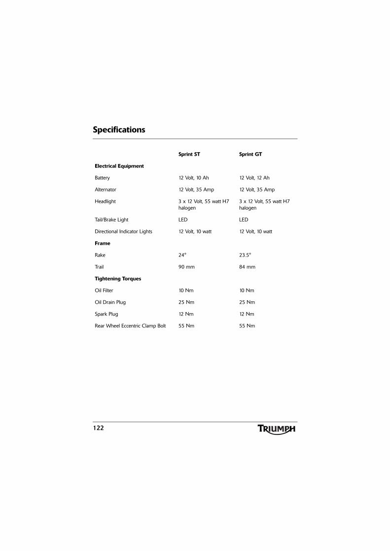
Specifications
122
Sprint ST Sprint GT
Electrical Equipment
Battery 12 Volt, 10 Ah 12 Volt, 12 Ah
Alternator 12 Volt, 35 Amp 12 Volt, 35 Amp
Headlight 3 x 12 Volt, 55 watt H7 halogen
3 x 12 Volt, 55 watt H7 halogen
Tail/Brake Light LED LED
Directional Indicator Lights 12 Volt, 10 watt 12 Volt, 10 watt
Frame
Rake 24° 23.5°
Trail 90 mm 84 mm
Tightening Torques
Oil Filter 10 Nm 10 Nm
Oil Drain Plug 25 Nm 25 Nm
Spark Plug 12 Nm 12 Nm
Rear Wheel Eccentric Clamp Bolt 55 Nm 55 Nm
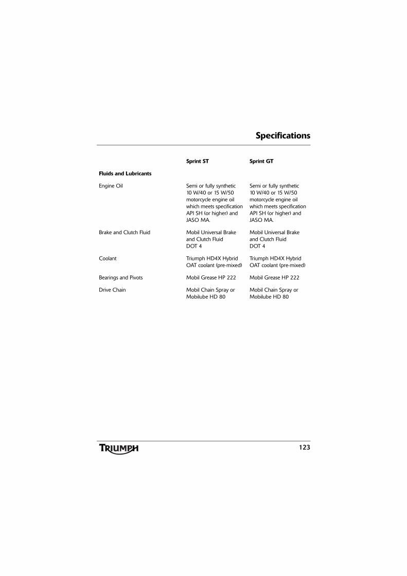
Specifications
123
Sprint ST Sprint GT
Fluids and Lubricants
Engine Oil Semi or fully synthetic 10 W/40 or 15 W/50 motorcycle engine oil which meets specification API SH (or higher) and JASO MA.
Semi or fully synthetic 10 W/40 or 15 W/50 motorcycle engine oil which meets specification API SH (or higher) and JASO MA.
Brake and Clutch Fluid Mobil Universal Brake and Clutch FluidDOT 4
Mobil Universal Brake and Clutch FluidDOT 4
Coolant Triumph HD4X Hybrid OAT coolant (pre-mixed)
Triumph HD4X Hybrid OAT coolant (pre-mixed)
Bearings and Pivots Mobil Grease HP 222 Mobil Grease HP 222
Drive Chain Mobil Chain Spray or Mobilube HD 80
Mobil Chain Spray or Mobilube HD 80
Specifications
124
This page intentionally left blank
125
Index
INDEX
BBattery . . . . . . . . . . . . . . . . . . . . . . . . . . . . 99
Charging . . . . . . . . . . . . . . . . . . . . . . 101Disposal . . . . . . . . . . . . . . . . . . . . . . 100Installation . . . . . . . . . . . . . . . . . . . . 102Maintenance . . . . . . . . . . . . . . . . . . 100Removal . . . . . . . . . . . . . . . . . . . . . . . 99
Brakes . . . . . . . . . . . . . . . . . . . . . . . . . . . . 84Brake and Clutch Lever Adjusters . . . 31Brake Pad Wear Compensation . . . . 85Brake Wear Inspection . . . . . . . . . . . 84Disc Brake Fluid . . . . . . . . . . . . . . . . . 86Fluid Level . . . . . . . . . . . . . . . . . . . . . 87Light Switches . . . . . . . . . . . . . . . . . . 89
CCleaning . . . . . . . . . . . . . . . . . . . . . . . . . . 112
After Washing . . . . . . . . . . . . . . . . . . 113Drying . . . . . . . . . . . . . . . . . . . . . . . . 114Exhaust System . . . . . . . . . . . . . . . . . 114Preparation. . . . . . . . . . . . . . . . . . . . . 112Protecting. . . . . . . . . . . . . . . . . . . . . . 114Unpainted Aluminium Items. . . . . . . 114Washing. . . . . . . . . . . . . . . . . . . . . . . 114Where to be Careful . . . . . . . . . . . . . 113
Clock/Trip Computer . . . . . . . . . . . . . . . . 23Clutch . . . . . . . . . . . . . . . . . . . . . . . . . . . . 80
Adjustment . . . . . . . . . . . . . . . . . . . . 80Inspection. . . . . . . . . . . . . . . . . . . . . . 80
Cooling System. . . . . . . . . . . . . . . . . 75, 118Coolant Change . . . . . . . . . . . . . . . . 77Coolant Level Inspection . . . . . . . . . . 76Corrosion Inhibitors . . . . . . . . . . . . . . 75Level Adjustment. . . . . . . . . . . . . . . . 76Radiator Hoses. . . . . . . . . . . . . . . . . . 77Temperature Gauge . . . . . . . . . . . . . 25
DDimensions . . . . . . . . . . . . . . . . . . . . . . . 117Drive Chain . . . . . . . . . . . . . . . . . . . . . . . . 81
Chain Lubrication. . . . . . . . . . . . . . . . 81Movement Adjustment . . . . . . . . . . . 82Movement Inspection . . . . . . . . . . . . 82Wear Inspection . . . . . . . . . . . . . . . . . 83
EElectrical Equipment . . . . . . . . . . . . . . . . 122Engine
Serial Number . . . . . . . . . . . . . . . . . . 17Specifications . . . . . . . . . . . . . . . . . . 117To Start the Engine . . . . . . . . . . . . . . 50To Stop the Engine . . . . . . . . . . . . . . 50
Engine Oil . . . . . . . . . . . . . . . . . . . . . . . . . 71Disposal of Used Oil and Filters . . . . 74Oil Level Inspection . . . . . . . . . . . . . . 71Specification and Grade. . . . . . . . . . . 74
FFluids and Lubricants . . . . . . . . . . . . . . . 123Frame. . . . . . . . . . . . . . . . . . . . . . . . . . . . 122Fuel . . . . . . . . . . . . . . . . . . . . . . . . . . . . . 118Fuel Gauge . . . . . . . . . . . . . . . . . . . . . . . . 26Fuel Requirement . . . . . . . . . . . . . . . . . . . 34
Filling the Fuel Tank. . . . . . . . . . . . . . 36Fuel Grade . . . . . . . . . . . . . . . . . . . . . 34Fuel Tank Cap . . . . . . . . . . . . . . . . . . 35
Fuel System . . . . . . . . . . . . . . . . . . . . . . . 118Fuse Box . . . . . . . . . . . . . . . . . . . . . . . . . 102
Fuse Identification - Sprint GT . . . . . 104Fuse Identification - Sprint ST . . . . . 103
GGears
Changing Gears. . . . . . . . . . . . . . . . . 52
126
Index
HHeadlights . . . . . . . . . . . . . . . . . . . . . . . . 105
Adjustment . . . . . . . . . . . . . . . . . . . 106Dipped Headlight Adjustment . . . . 107Dipped Headlight Bulb Replacement . . . . . . . . . . . . . . . . . . 108Main Beam Headlight Adjustment . 106Main Beam Headlight Bulb Replacement . . . . . . . . . . . . . . . . . . 108Position Lamp Bulb Replacement . . 109
IIgnition . . . . . . . . . . . . . . . . . . . . . . . . . . . 119
Key . . . . . . . . . . . . . . . . . . . . . . . . . . . 29Switch/Steering Lock . . . . . . . . . . . . . 30
Instrument Panel Layout . . . . . . . . . . . . . . 21
LLeft Handlebar Switches
Direction Indicator Switch . . . . . . . . . 34Horn Button. . . . . . . . . . . . . . . . . . . . 34Pass Button . . . . . . . . . . . . . . . . . . . . 34
Licence Plate Light . . . . . . . . . . . . . . . . . . 111Lubrication . . . . . . . . . . . . . . . . . . . . . . . . 118
OOdometer/Trip Meter . . . . . . . . . . . . . . . 22
PPannier System - Sprint GT . . . . . . . . . . . . 41Parts Identification
Sprint GT . . . . . . . . . . . . . . . . . . . . . . . 14Sprint ST . . . . . . . . . . . . . . . . . . . . . . . 12
Performance . . . . . . . . . . . . . . . . . . . . . . . 118
RRear Light . . . . . . . . . . . . . . . . . . . . . . . . 109Right Handlebar Switches . . . . . . . . . . . . 32
Engine Stop Switch . . . . . . . . . . . . . . 32Starter Button. . . . . . . . . . . . . . . . . . . 33
SSafety . . . . . . . . . . . . . . . . . . . . . . . . . . . . . . 5
Fuel and Exhaust Fumes . . . . . . . . . . . 5Handlebars and Footrests . . . . . . . . . . 7Helmet and Clothing . . . . . . . . . . . . . . 7Maintenance/Equipment . . . . . . . . . . . 9Motorcycle . . . . . . . . . . . . . . . . . . . . . . 5Parking . . . . . . . . . . . . . . . . . . . . . . . . . 8Parts and Accessories . . . . . . . . . . . . . . 8Riding . . . . . . . . . . . . . . . . . . . . . . . . . . 6
Seat Care . . . . . . . . . . . . . . . . . . . . . . . . . 113Speedometer. . . . . . . . . . . . . . . . . . . . . . . 22Storage . . . . . . . . . . . . . . . . . . . . . . . . . . 115
Preparation after Storage . . . . . . . . . 116Preparation for Storage . . . . . . . . . . 115
TTachometer . . . . . . . . . . . . . . . . . . . . . . . . 22Tightening Torques. . . . . . . . . . . . . . . . . 122Transmission . . . . . . . . . . . . . . . . . . . . . . 119Tyres . . . . . . . . . . . . . . . . . . . . . . . . 120, 121
VVehicle Identification Number . . . . . . . . . 17
WWarnings
Warning Label Locations . . . . . . . . . . 10Warning Labels . . . . . . . . . . . . . . . . . . 2Warning Lights. . . . . . . . . . . . . . . . . . 27Warnings, Cautions and Notes . . . . . . 1
Weights . . . . . . . . . . . . . . . . . . . . . . . . . . 117Windscreen Cleaning . . . . . . . . . . . . . . . 111