Embed Size (px)
Citation preview
NAV - 247 1
Installation instructions:
AKRAPOVIC RACING & EVOLUTION, EXHAUST SYSTEM
for the YAMAHA FZ1, FZ1 FAZER
Congratulations on purchasing an Akrapovic exhaust system. Please read these installation instructions carefully. If you have any trouble installing the system please contact your authorized dealer! IMPORTANT INFORMATION Exclusion of Certain Liability
1. The manufacturer, importer or dealer shall not be liable for any incidental damage including personal injury or any other damages caused by improper installation or operation of the Akrapovic exhaust system. When installing the Akrapovic exhaust system be careful that the exhaust system does not touch other parts sensitive to high temperature.
2. Akrapovic makes no representation or warranties with regard to damage caused by the improper installation, use and
maintenance of the Akrapovic exhaust system. The warranty is limited to defects recognized by our technical department and to normal use, and excludes items subject to normal wear (gaskets and damping wool). The guarantee is void in case of accident, modification, improper or competition use.
3. Do not attempt to install the Akrapovic exhaust system on a motorcycle for which it was not made or tested by
Akrapovic.
4. When the exhaust system gets very hot during operation, be careful not to burn yourself on the exhaust system or parts which are in direct contact with it, even when the motor is not running. Also protect other people, especially children, from the injuries mentioned above.
5. In some cases Akrapovic exhaust system kits contain chemical products (ceramic anti-seizing grease; bolt sealant).
Handle with care, do not inhale or swallow. Avoid excessive contact with skin, eyes or mucous membranes. Keep out of reach of children.
6. Technical specifications of Akrapovic exhaust systems and related products subject to change without notice.
Trademarks
The Akrapovic Exhaust System Technology logo is a registered trademark of Akrapovic d.d. Akrapovic website
Information about Akrapovic exhaust systems and related products is available on the Akrapovic website at:
http://www.akrapovic.com/ Copyright
No part of the Akrapovic exhaust system or its documentation may be reproduced or distributed in any form or by any means without the prior written authorization of the Akrapovic company.
Akrapovic, d.d. All rights reserved.
Symbols The following symbols are used throughout these installation instructions:
! CAUTION OR WARNING INSTALLATION TIP
TOOLS
REQUIRED
TIGHTENING
TORQUE
USE BOLT SEALANT; Apply 3 to 4 small drops of bolt sealant onto the cleaned and degreased threads before tightening bolts. WARNING! Avoid contact with skin, eyes and mucous membranes. Do not inhale fumes. Keep out of the reach of children.
USE ANTI-SEIZE LEAD-FREE COPPER PASTE (black tube); Provides trouble-free and long-lasting protection against seizing, corrosion and rusting of bolts, threaded ends, nuts, joints, etc. Also protects against vibration, wear and impact. WARNING! Avoid eye contact. Avoid excessive skin contact. Keep out of the reach of children.
USE ANTI-SEIZING GREASE (white tube); Prevents seizing, corrosion and excessive wear between the titanium components of your exhaust system. WARNING! Avoid eye contact. Avoid excessive skin contact. Keep out of the reach of children.
*350335*
NAV - 247 2
INSTALLATION INSTRUCTIONS
BEFORE INSTALLING CHECK SCHEMATIC OF THE EXHAUST SYSTEM!
! IF ANY ITEMS IN THE AKRAPOVIC EXHAUST SYSTEM PACKAGE ARE MISSING PLEASE CONTACT YOUR AUTHORIZED DEALER. KEEP THE SCHEMATIC FOR FUTURE REFERENCE.
! THESE INSTALLATION INSTRUCTIONS MUST BE READ CAREFULLY IN ORDER TO ENSURE PROPER INSTALLATION AND OPERATION OF THE AKRAPOVIC EXHAUST SYSTEM.
! THE EXHAUST SYSTEM CAN BE EXTREMELY HOT. ALLOW THE MOTORCYCLE TO COOL DOWN BEFORE BEGINNING INSTALLATION.
WE ADVISE YOU TO LEAVE INSTALLATION TO A QUALIFIED SERVICEMAN. IMPROPER INSTALLATION MAY RESULT IN A SHORTER LIFETIME OF THE EXHAUST SYSTEM AND/OR DAMAGE TO THE MOTORCYCLE.
REMOVAL OF STOCK EXHAUST SYSTEM:
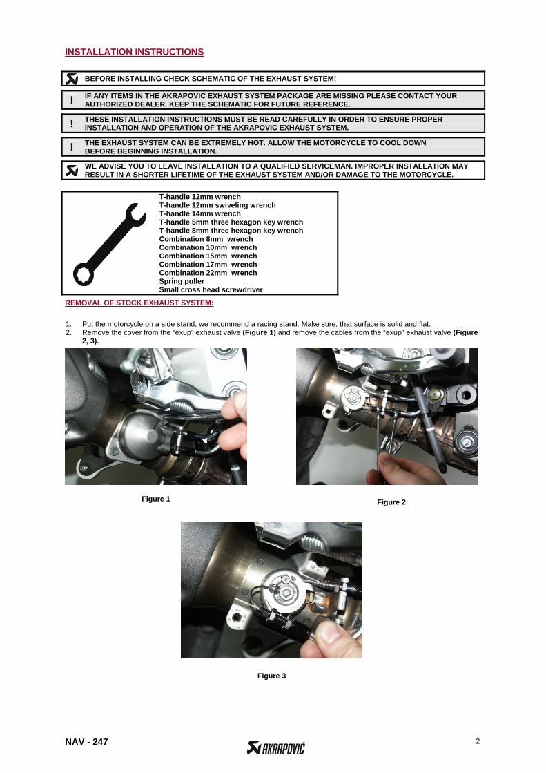
1. Put the motorcycle on a side stand, we recommend a racing stand. Make sure, that surface is solid and flat. 2. Remove the cover from the “exup” exhaust valve (Figure 1) and remove the cables from the “exup” exhaust valve (Figure
2, 3).
T-handle 12mm wrench T-handle 12mm swiveling wrench T-handle 14mm wrench T-handle 5mm three hexagon key wrench T-handle 8mm three hexagon key wrench Combination 8mm wrench Combination 10mm wrench Combination 15mm wrench Combination 17mm wrench Combination 22mm wrench Spring puller Small cross head screwdriver
Figure 2
Figure 3
Figure 1
NAV - 247 3
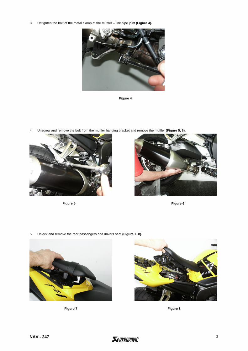
3. Untighten the bolt of the metal clamp at the muffler – link pipe joint (Figure 4). 4. Unscrew and remove the bolt from the muffler hanging bracket and remove the muffler (Figure 5, 6).
5. Unlock and remove the rear passengers and drivers seat (Figure 7, 8).
Figure 4
Figure 5 Figure 6
Figure 7 Figure 8
NAV - 247 4
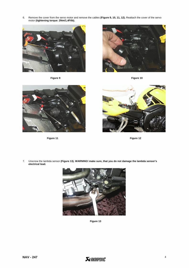
6. Remove the cover from the servo motor and remove the cables (Figure 9, 10, 11, 12). Reattach the cover of the servo motor (tightening torque: 2Nm/1,4Ftlb).
7. Unscrew the lambda sensor (Figure 13). WARNING! make sure, that you do not damage the lambda sensor’s
electrical lead.
Figure 9 Figure 10
Figure 11 Figure 12
Figure 13
NAV - 247 5
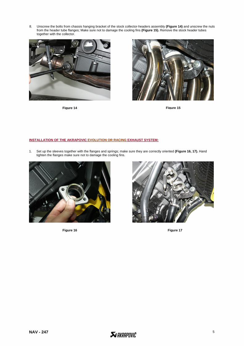
8. Unscrew the bolts from chassis hanging bracket of the stock collector-headers assembly (Figure 14) and unscrew the nuts
from the header tube flanges; Make sure not to damage the cooling fins (Figure 15). Remove the stock header tubes together with the collector.
INSTALLATION OF THE AKRAPOVIC EVOLUTION OR RACING EXHAUST SYSTEM: 1. Set up the sleeves together with the flanges and springs; make sure they are correctly oriented (Figure 16, 17). Hand
tighten the flanges make sure not to damage the cooling fins.
Figure 14 Figure 15
Figure 16 Figure 17
NAV - 247 6
Figure 19
Figure 23
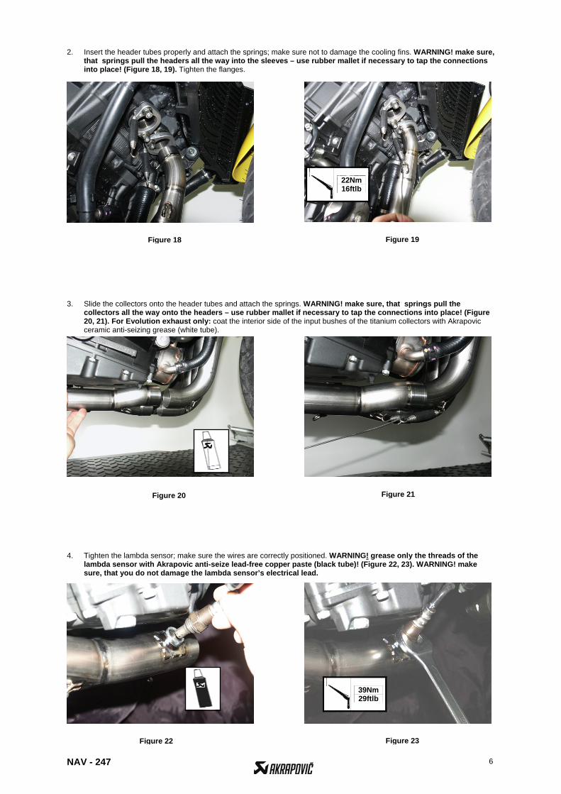
2. Insert the header tubes properly and attach the springs; make sure not to damage the cooling fins. WARNING! make sure, that springs pull the headers all the way into the sleeves – use rubber mallet if necessary to tap the connections into place! (Figure 18, 19). Tighten the flanges.
3. Slide the collectors onto the header tubes and attach the springs. WARNING! make sure, that springs pull the
collectors all the way onto the headers – use rubber mallet if necessary to tap the connections into place! (Figure 20, 21). For Evolution exhaust only: coat the interior side of the input bushes of the titanium collectors with Akrapovic ceramic anti-seizing grease (white tube).
4. Tighten the lambda sensor; make sure the wires are correctly positioned. WARNING! grease only the threads of the
lambda sensor with Akrapovic anti-seize lead-free copper paste (black tube)! (Figure 22, 23). WARNING! make sure, that you do not damage the lambda sensor’s electrical lead.
22Nm 16ftlb
39Nm 29ftlb
Figure 18
Figure 20 Figure 21
Figure 22
NAV - 247 7
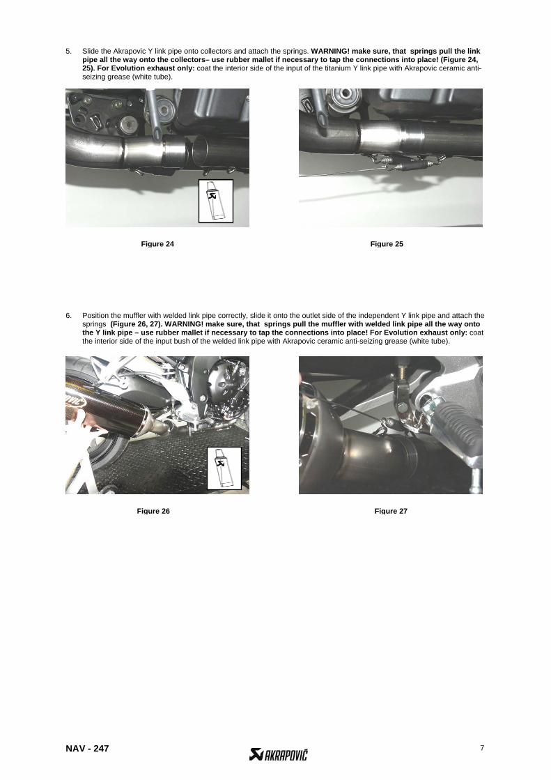
5. Slide the Akrapovic Y link pipe onto collectors and attach the springs. WARNING! make sure, that springs pull the link pipe all the way onto the collectors– use rubber mallet if necessary to tap the connections into place! (Figure 24, 25). For Evolution exhaust only: coat the interior side of the input of the titanium Y link pipe with Akrapovic ceramic anti-seizing grease (white tube).
6. Position the muffler with welded link pipe correctly, slide it onto the outlet side of the independent Y link pipe and attach the
springs (Figure 26, 27). WARNING! make sure, that springs pull the muffler with welded link pipe all the way onto the Y link pipe – use rubber mallet if necessary to tap the connections into place! For Evolution exhaust only: coat the interior side of the input bush of the welded link pipe with Akrapovic ceramic anti-seizing grease (white tube).
Figure 24 Figure 25
Figure 26 Figure 27
NAV - 247 8
Figure 32
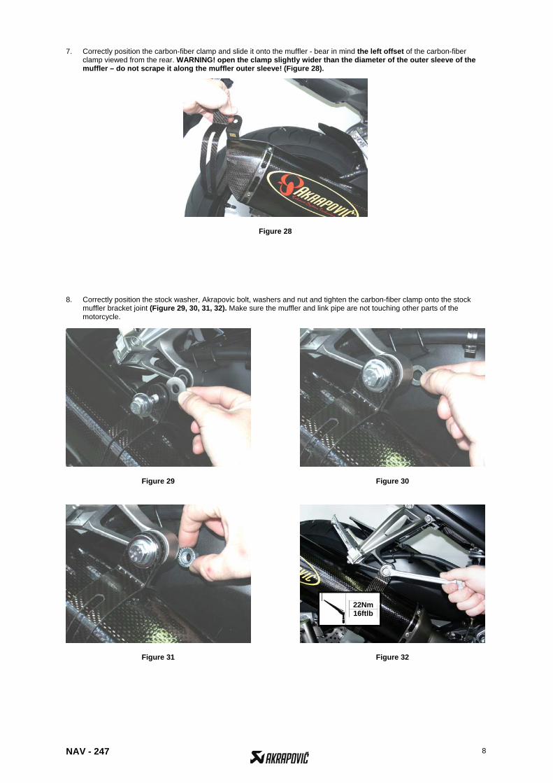
7. Correctly position the carbon-fiber clamp and slide it onto the muffler - bear in mind the left offset of the carbon-fiber clamp viewed from the rear. WARNING! open the clamp slightly wider than the diameter of the outer sleeve of the muffler – do not scrape it along the muffler outer sleeve! (Figure 28).
8. Correctly position the stock washer, Akrapovic bolt, washers and nut and tighten the carbon-fiber clamp onto the stock
muffler bracket joint (Figure 29, 30, 31, 32). Make sure the muffler and link pipe are not touching other parts of the motorcycle.
22Nm 16ftlb
Figure 28
Figure 29 Figure 30
Figure 31
NAV - 247 9
Figure 36
Figure 37
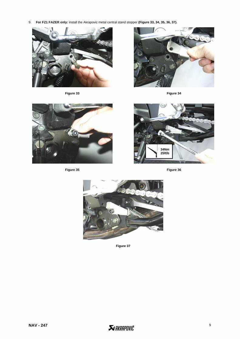
9. For FZ1 FAZER only: install the Akrapovic metal central stand stopper (Figure 33, 34, 35, 36, 37).
34Nm 25ftlb
Figure 33 Figure 34
Figure 35
NAV - 247 10
Final installation: 1. Clean grease spots:
a. Muffler – carbon-fiber outer sleeve: use a soft dry cloth. b. Muffler – titanium outer sleeve: use a soft cloth sprayed with a multi-purpose spray lubricant (WD-40 or
equivalent). c. Muffler – carbon-fiber outlet cap: use a soft dry cloth. d. RACING - stainless steel link pipe, collectors and header tubes: use a soft cloth sprayed with a contact cleaner,
then wipe with a soft dry cloth e. EVOLUTION - titanium link pipe, collectors and header tubes : use a soft cloth sprayed with a multi-purpose
spray lubricant (WD-40 or equivalent).
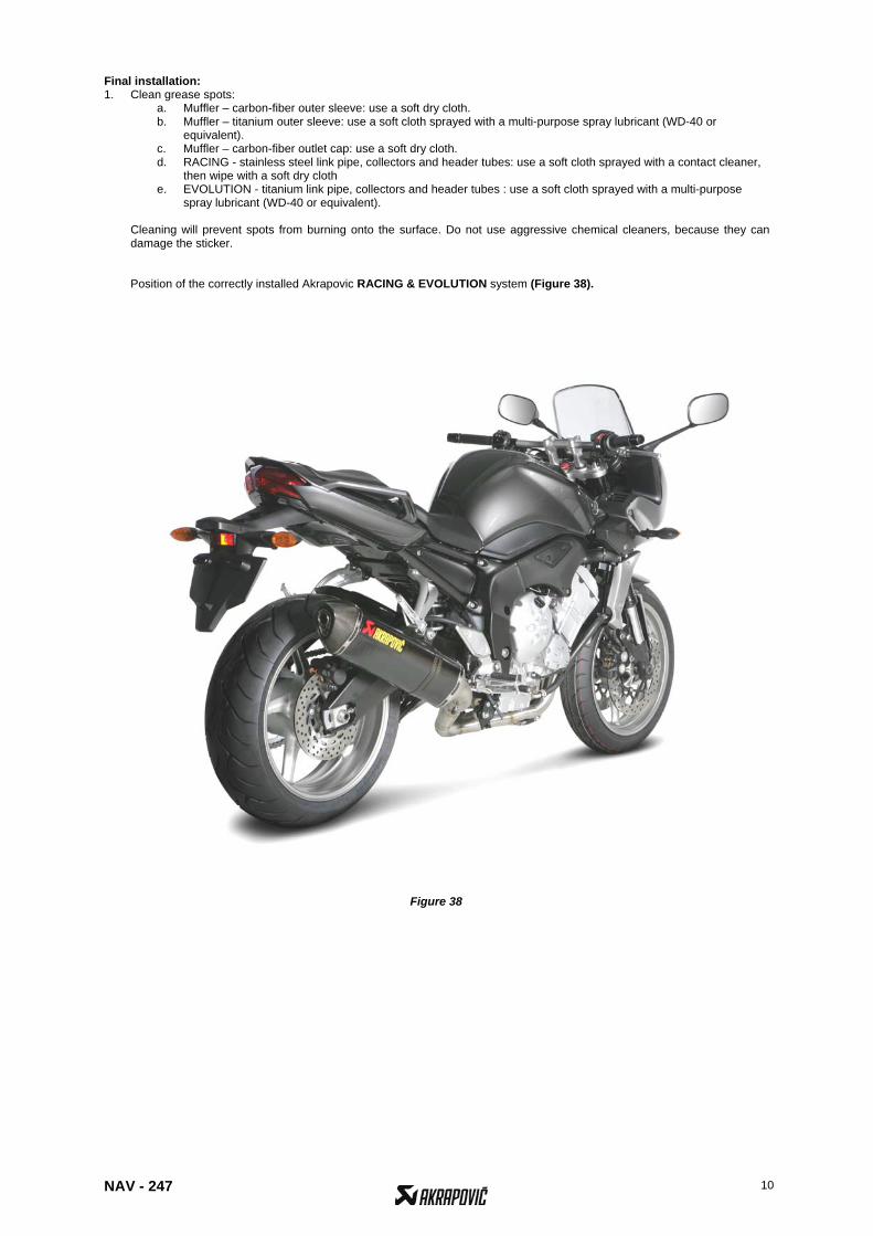
Cleaning will prevent spots from burning onto the surface. Do not use aggressive chemical cleaners, because they can damage the sticker. Position of the correctly installed Akrapovic RACING & EVOLUTION system (Figure 38).
Figure 38
NAV - 247 11
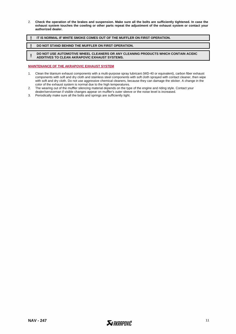
2. Check the operation of the brakes and suspension. Make sure all the bolts are sufficiently tightened. In case the exhaust system touches the cowling or other parts repeat the adjustment of the exhaust system or contact your authorized dealer.
! IT IS NORMAL IF WHITE SMOKE COMES OUT OF THE MUFFLER ON FIRST OPERATION.
! DO NOT STAND BEHIND THE MUFFLER ON FIRST OPERATION.
! DO NOT USE AUTOMOTIVE WHEEL CLEANERS OR ANY CLEANING PRODUCTS WHICH CONTAIN ACIDIC ADDITIVES TO CLEAN AKRAPOVIC EXHAUST SYSTEMS.
MAINTENANCE OF THE AKRAPOVIC EXHAUST SYSTEM 1. Clean the titanium exhaust components with a multi-purpose spray lubricant (WD-40 or equivalent), carbon fiber exhaust
components with soft and dry cloth and stainless steel components with soft cloth sprayed with contact cleaner, then wipe with soft and dry cloth. Do not use aggressive chemical cleaners, because they can damage the sticker. A change in the color of the exhaust system is normal due to the high temperatures.
2. The wearing out of the muffler silencing material depends on the type of the engine and riding style. Contact your dealer/serviceman if visible changes appear on muffler's outer sleeve or the noise level is increased.
3. Periodically make sure all the bolts and springs are sufficiently tight.
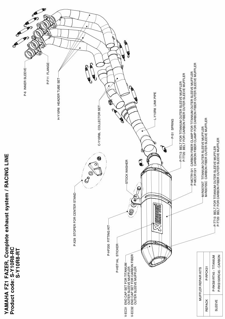
YA
MA
HA
FZ1
FAZER
, C
ompl
ete
exha
ust
syst
em / R
AC
ING
LIN
E
Pro
duct
cod
e: S
-Y10
R8-
RC
S
-Y10
R8-
RT
P-X
29 S
TOP
ER
FO
R C
EN
TER
STA
ND
P-H
F200
FIT
TIN
G K
IT
P-M
CTR
13/1
CA
RB
ON
FIB
ER
CLA
MP
FO
R T
ITA
NIU
M O
UTE
R S
LEE
VE
MU
FFLE
RP
-MC
CR
13/1
CA
RB
ON
FIB
ER
CLA
MP
FO
R C
AR
BO
N F
IBE
R O
UTE
R S
LEE
VE
MU
FFLE
R
M-R
0070
5T T
ITA
NIU
M O
UTE
R S
LEE
VE
MU
FFLE
RM
-R00
705C
CA
RB
ON
FIB
ER
OU
TER
SLE
EV
E M
UFF
LERL-
Y10
R8
LIN
K P
IPE
P-6
IN
NE
R S
LEE
VE
P-F
11 F
LAN
GE
P-S
1 S
PR
ING
C-Y
10R
8L C
OLL
EC
TOR
SE
T
H-Y
10R
6 H
EA
DE
R T
UB
E S
ET
P-H
ST1
AL
STI
CK
ER
STO
CK
WA
SH
ER P
-TT1
3 B
ELT
FO
R T
ITA
NIU
M O
UTE
R S
LEE
VE
MU
FFLE
RP
-TT2
0 B
ELT
FO
R C
AR
BO
N F
IBE
R O
UTE
R S
LEE
VE
MU
FFLE
R
P-T
T13
BE
LT F
OR
TIT
AN
IUM
OU
TER
SLE
EV
E M
UFF
LER
P-T
T20
BE
LT F
OR
CA
RB
ON
FIB
ER
OU
TER
SLE
EV
E M
UFF
LER
V-E
C31
EN
D C
AP
SE
T FO
R T
ITA
NIU
M
OU
TER
SLE
EV
E M
UFF
LER
V-E
C32
EN
D C
AP
SE
T FO
R C
AR
BO
N F
IBE
R
O
UTE
R S
LEE
VE
MU
FFLE
R
MU
FFLE
R R
EP
AIR
KIT
S
RE
PA
CK
P-R
PC
K31
SLE
EV
EP
-RK
S81
RT4
5 - T
ITA
NIU
M
P-R
KS
100R
C45
- C
AR
BO
N
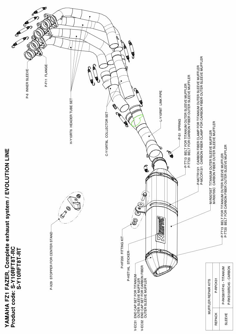
YA
MA
HA
FZ1
FAZER
, C
ompl
ete
exha
ust
syst
em / E
VO
LUTIO
N L
INE
Pro
duct
cod
e: S
-Y10
RFT
8T-R
C S
-Y10
RFT
8T-R
T
P-X
29 S
TOP
PE
R F
OR
CE
NTE
R S
TAN
D
P-H
F200
FIT
TIN
G K
IT
P-M
CTR
13/1
CA
RB
ON
FIB
ER
CLA
MP
FO
R T
ITA
NIU
M O
UTE
R S
LEE
VE
MU
FFLE
RP
-MC
CR
13/1
CA
RB
ON
FIB
ER
CLA
MP
FO
R C
AR
BO
N F
IBE
R O
UTE
R S
LEE
VE
MU
FFLE
R
M-R
0070
5T T
ITA
NIU
M O
UTE
R S
LEE
VE
MU
FFLE
RM
-R00
705C
CA
RB
ON
FIB
ER
OU
TER
SLE
EV
E M
UFF
LERL-
Y10
R8T
LIN
K P
IPE
P-6
IN
NE
R S
LEE
VE
P-F
11 F
LAN
GE
P-S
1 S
PR
ING
C-Y
10R
T8L
CO
LLE
CTO
R S
ET
H-Y
10R
T6 H
EA
DE
R T
UB
E S
ET
P-H
ST1
AL
STI
CK
ER
V-E
C31
EN
D C
AP
SE
T FO
R T
ITA
NIU
M
O
UTE
R S
LEE
VE
MU
FFLE
RV
-EC
32 E
ND
CA
P S
ET
FOR
CA
RB
ON
FIB
ER
OU
TER
SLE
EV
E M
UFF
LER
P-T
T13
BE
LT F
OR
TIT
AN
IUM
OU
TER
SLE
EV
E M
UFF
LER
P-T
T20
BE
LT F
OR
CA
RB
ON
FIB
ER
OU
TER
SLE
EV
E M
UFF
LER
P-T
T13
BE
LT F
OR
TIT
AN
IUM
OU
TER
SLE
EV
E M
UFF
LER
P-T
T20
BE
LT F
OR
CA
RB
ON
FIB
ER
OU
TER
SLE
EV
E M
UFF
LER
MU
FFLE
R R
EP
AIR
KIT
S
RE
PA
CK
P-R
PC
K31
SLE
EV
EP
-RK
S81
RT4
5 - T
ITA
NIU
M
P-R
KS
100R
C45
- C
AR
BO
N
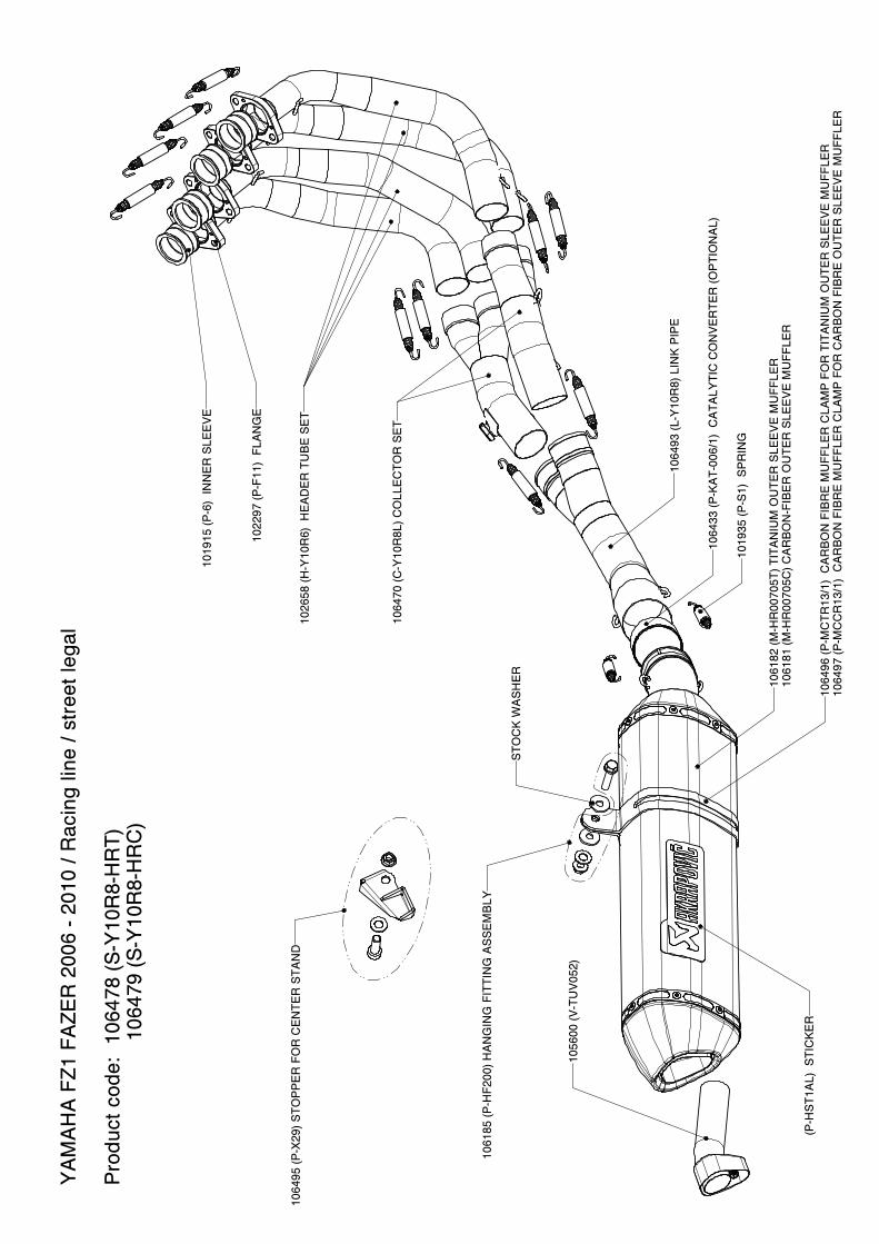
YA
MA
HA
FZ1
FA
ZER
200
6 - 2
010
/ Rac
ing
line
/ str
eet l
egal
Pro
duct
cod
e: 1
0647
8 (S
-Y10
R8-
HR
T)
10
6479
(S-Y
10R
8-H
RC
)
1064
96 (P
-MC
TR13
/1)
CA
RB
ON
FIB
RE
MU
FFLE
R C
LAM
P F
OR
TIT
AN
IUM
OU
TER
SLE
EV
E M
UFF
LER
1064
97 (P
-MC
CR
13/1
) C
AR
BO
N F
IBR
E M
UFF
LER
CLA
MP
FO
R C
AR
BO
N F
IBR
E O
UTE
R S
LEE
VE
MU
FFLE
R
1061
82 (M
-HR
0070
5T) T
ITA
NIU
M O
UTE
R S
LEE
VE
MU
FFLE
R10
6181
(M-H
R00
705C
) CA
RB
ON
-FIB
ER
OU
TER
SLE
EV
E M
UFF
LER
1064
93 (L
-Y10
R8)
LIN
K P
IPE
1019
15 (P
-6)
INN
ER
SLE
EV
E
1019
35 (P
-S1)
SP
RIN
G
1064
70 (C
-Y10
R8L
) CO
LLE
CTO
R S
ET
1026
58 (H
-Y10
R6)
HE
AD
ER
TU
BE
SE
T
1064
33 (P
-KA
T-00
6/1)
CA
TALY
TIC
CO
NV
ER
TER
(OP
TIO
NA
L)
1064
95 (P
-X29
) STO
PP
ER
FO
R C
EN
TER
STA
ND
1061
85 (P
-HF2
00) H
AN
GIN
G F
ITTI
NG
AS
SE
MB
LY
STO
CK
WA
SH
ER
1056
00 (V
-TU
V05
2)
1022
97 (P
-F11
) FL
AN
GE
(P-H
ST1
AL)
STI
CK
ER
YA
MA
HA
FZ1
FA
ZER
200
6 - 2
010
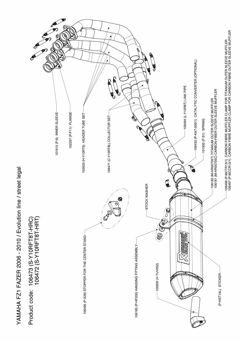
/ Evo
lutio
n lin
e / s
tree
t leg
al P
rodu
ct c
ode:
106
473
(S-Y
10R
FT8T
-HR
C)
1064
72 (S
-Y10
RFT
8T-H
RT)
1064
96 (P
-MC
TR13
/1)
CA
RB
ON
FIB
RE
MU
FFLE
R C
LAM
P F
OR
TIT
AN
IUM
OU
TER
SLE
EV
E M
UFF
LER
1064
97 (P
-MC
CR
13/1
) C
AR
BO
N F
IBR
E M
UFF
LER
CLA
MP
FO
R C
AR
BO
N F
IBR
E O
UTE
R S
LEE
VE
MU
FFLE
R
1061
82 (M
-HR
0070
5T) T
ITA
NIU
M O
UTE
R S
LEE
VE
MU
FFLE
R10
6181
(M-H
R00
705C
) CA
RB
ON
-FIB
ER
OU
TER
SLE
EV
E M
UFF
LER
1064
94 (L
-Y10
R8T
) LIN
K P
IPE
1019
15 (P
-6)
INN
ER
SLE
EV
E
1019
35 (P
-S1)
SP
RIN
G
1064
71 (C
-Y10
RT8
L) C
OLL
EC
TOR
SE
T
1026
33 (H
-Y10
RT6
) H
EA
DE
R T
UB
E S
ET
1064
33 (P
-KA
T-00
6/1)
CA
TALY
TIC
CO
NV
ER
TER
(OP
TIO
NA
L)
1064
95 (P
-X29
) STO
PP
ER
FO
R T
HE
CE
NTE
R S
TAN
D
1061
85 (P
-HF2
00) H
AN
GIN
G F
ITTI
NG
AS
SE
MB
LY
STO
CK
WA
SH
ER
1056
00 (V
-TU
V05
2)
1022
97 (P
-F11
) FL
AN
GE
(P-H
ST1
AL)
STI
CK
ER

WARNING:
Please note that certain aftermarket exhaust systems may not comply with applicable California laws and regulations, and may therefore be prohibited for use on California highways or roads, or on roads or vehicles otherwise subject to emissions control requirements.Akrapovič exhaust systems for automobiles and motorcycles mounted downstream of the catalytic converter (also known as “cat-back systems”) are considered “replacement parts” in California by the California Air Resources Board (CARB), and do not require an exemption or executive order from CARB to be sold in California. However, California prohibits the use of any aftermarket exhaust system that modifies, removes or replaces original equipment catalysts, unless CARB has issued an Executive Order as to such part or system.Further, Akrapovič parts or exhaust systems used or intended for use on “racing vehicles” (i.e. a competition vehicle used exclusively for competition on closed-course circuits) do not require an exemption or Executive Order from CARB to be sold in California. However, such parts are prohibited from use on California public highways or roads, even if occasionally used “off-road.”