Embed Size (px)
Citation preview
FUEL SYSTEM DURABILITY— U.S. COAST GUARD
INTERIM REPORT TFLRF No. 393
by Douglas M. Yost
U.S. Army TARDEC Fuels and Lubricants Research Facility Southwest Research Institute® (SwRI®)
San Antonio, TX
for U.S. Army TARDEC
Force Projection Technologies Warren, Michigan
Contract No. DAAE-07-99-C-L053 (WD20) SwRI Project No. 08.03227.20.001
Approved for public release: distribution unlimited
May 2008
ADA
Disclaimers The findings in this report are not to be construed as an official Department of the Army position unless so designated by other authorized documents. Trade names cited in this report do not constitute an official endorsement or approval of the use of such commercial hardware or software.
DTIC Availability Notice Qualified requestors may obtain copies of this report from the Defense Technical Information Center, Attn: DTIC-OCC, 8725 John J. Kingman Road, Suite 0944, Fort Belvoir, Virginia 22060-6218.
Disposition Instructions Destroy this report when no longer needed. Do not return it to the originator.
FUEL SYSTEM DURABILITY— U.S. COAST GUARD
INTERIM REPORT TFLRF No. 393
by Douglas M. Yost
U.S. Army TARDEC Fuels and Lubricants Research Facility
Southwest Research Institute® (SwRI®) San Antonio, TX
for U.S. Army TARDEC
Force Projection Technologies Warren, Michigan
Contract No. DAAE-07-99-C-L053 (WD20) SwRI® Project No. 03.03227.20.001
Approved for public release: distribution unlimited
May 2008 Approved by: Steven D. Marty, Director U.S. Army TARDEC Fuels and Lubricants
Research Facility (SwRI®)
iv
REPORT DOCUMENTATION PAGE Form Approved OMB No. 0704-0188
Public reporting burden for this collection of information is estimated to average 1 hour per response, including the time for reviewing instructions, searching existing data sources, gathering and maintaining the data needed, and completing and reviewing this collection of information. Send comments regarding this burden estimate or any other aspect of this collection of information, including suggestions for reducing this burden to Department of Defense, Washington Headquarters Services, Directorate for Information Operations and Reports (0704-0188), 1215 Jefferson Davis Highway, Suite 1204, Arlington, VA 22202-4302. Respondents should be aware that notwithstanding any other provision of law, no person shall be subject to any penalty for failing to comply with a collection of information if it does not display a currently valid OMB control number. PLEASE DO NOT RETURN YOUR FORM TO THE ABOVE ADDRESS. 1. REPORT DATE (DD-MM-YYYY) 30-05-2008
2. REPORT TYPE Final Interim Report
3. DATES COVERED (From – To) September 2002 – January 2008
4. TITLE AND SUBTITLE Fuel System Durability—U.S. Coast Guard
5a. CONTRACT NUMBER DAAE07-99-C-L053
5b. GRANT NUMBER
5c. PROGRAM ELEMENT NUMBER
6. AUTHOR(S) Douglas M. Yost
5d. PROJECT NUMBER SwRI 08.03227.20.001
5e. TASK NUMBER WD 20
5f. WORK UNIT NUMBER
7. PERFORMING ORGANIZATION NAME(S) AND ADDRESS(ES) 8. PERFORMING ORGANIZATION REPORT NUMBER
U.S. Army TARDEC Fuels and Lubricants Research Facility (SwRI®) Southwest Research Institute® P.O. Drawer 28510 San Antonio, TX 78228-0510
TFLRF No. 393
9. SPONSORING / MONITORING AGENCY NAME(S) AND ADDRESS(ES) 10. SPONSOR/MONITOR’S ACRONYM(S)
U.S. Army RDECOM U.S. Coast Guard Engineering Logistics Ctr
U.S. Army TARDEC 2401 Hawkins Point Rd, Attn: Thomas Gahs 11. SPONSOR/MONITOR’S REPORT Force Projection Technologies Propulsion Equipment Branch ELC-026 NUMBER(S) Warren, MI 48397-5000 Baltimore, MD 21226-5000
12. DISTRIBUTION / AVAILABILITY STATEMENT Approved for public release; distribution unlimited 13. SUPPLEMENTARY NOTES 14. ABSTRACT This project attempted to determine the fuel lubricity requirements of the Sulzer 12ZAV40S fuel injection system. Wear rates with F-76 and JP-5 fuels were attempted using radioactive tracer technologies using a fuel injection system test stand. Within the sensitivity of the resulting activation, and due to detector instabilities, the wear of fuel injection components could not be quantified using on-line in-situ radioactivity monitoring techniques. Off-line monitoring did indicate wear, but only after a catastrophic wear event. The methods did indicate however that the wear with JP-5 fuel was not significantly different than Diesel Fuel Marine (DFM) fuel within the scope of the method with the high durability components. Recommendations were made for future testing.
15. SUBJECT TERMS marine diesel medium speed diesel F-76 JP-5 wear radioactive tracer surface layer activation HFRR cavitation contamination scuffing load scanning electron imaging 16. SECURITY CLASSIFICATION OF: 17. LIMITATION
OF ABSTRACT 18. NUMBER OF PAGES
19a. NAME OF RESPONSIBLE PERSON
a. REPORT Unclassified
b. ABSTRACT Unclassified
c. THIS PAGE Unclassified
Unclassified
68
19b. TELEPHONE NUMBER (include area code)
Standard Form 298 (Rev. 8-98) Prescribed by ANSI Std. Z39.18
v
EXECUTIVE SUMMARY
Problems: The ability to operate Wartsila/Sulzer 12ZAV40S engines in the US Coast Guard on
JP-5, and other alternate fuels, without fuel injection system durability impact is in question.
Data from the manufacturer on usage with alternate fuels has not been made readily available.
Objective: To determine the fuel lubricity requirements of the Sulzer 12ZAV40S fuel injection
system.
Importance of Project: The U.S. Coast Guard (USCG) prefers to obtain fuel from Navy
bunkers, primarily because F-76 has a stability requirement versus MGO, which does not have a
stability specification. The Navy is considering a one-fuel strategy, with the one-fuel being JP-5
grade aviation turbine fuel. Thus, the USCG wants to understand the impact of JP-5 on the fuel
injection equipment in large medium-speed diesel engines.
Technical Approach: Meaningful wear information can be acquired in short periods of
operation using radioactive tracer component activation methodologies. The wear rate with F-76
was to be determined along with JP-5 for comparison of relative component life. A recirculating
fuel system was utilized to improve measurement accuracy and to reduce fuel requirements
Accomplishments: A unit fuel injection pump test rig was designed and built for operating the
fuel injection system from one cylinder of a Sulzer 12ZAV40S diesel engine. A Surface Layer
Activation radioactive tracer experiment was designed for measuring wear rates between fuels.
Within the sensitivity of the resulting activation, and due to detector instabilities, the wear of fuel
injection components could not be quantified using on-line in-situ radioactivity monitoring
techniques. Off-line monitoring did indicate wear, but only after a catastrophic wear event. The
methods did indicate however that the wear with JP-5 fuel was not significantly different than
Diesel Fuel Marine (DFM) fuel within the scope of the method with the high durability
components (24,000-hour).
vi
Recommendations: Due to complications the radioactive tracer approach was not suitable to
determine wear in the 12ZAV40S fuel injection system. Some type of controlled durability test
would be required to determine suitability of JP-5. Indicators suggest short term JP-5 usage
would likely be suitable, however evidence of cavitation erosion suggest long term use may be
questionable. However the cavitation erosion seen was not documented for both fuels examined,
nor is it certain expanded speed operating conditions may have contributed to accelerating the
cavitation erosion. Two approaches are suggested for determining wear with JP-5:
• A controlled test of an operating engine where one cylinder is isolated to operate on JP-5
for a significant number of hours. Component condition would be compared to one of the
other cylinder conditions.
• A single pass pump rig test of a significant quantity of JP-5 fuel, such that the effects of
additive changes and fuel/oil migration are not compounded. The wear on the barrel and
plunger would be compared to an installed plunger removed from the Healy that has been
burning DFM.
vii
FOREWORD/ACKNOWLEDGMENTS
The U.S. Army TARDEC Fuel and Lubricants Research Facility (TFLRF) located at Southwest
Research Institute (SwRI), San Antonio, Texas, performed this work during the period
September 2002 through January 2008 under Contract No. DAAE-07-99-C-L053. The U.S.
Army Tank-Automotive RD&E Center (TARDEC), Force Projection Technologies, Warren,
Michigan, administered the project. Mr. Luis Villahermosa (AMSRD-TAR-D, MS110) served as
the TARDEC contracting officer’s technical representative, and Mr. Thomas Gahs, United States
Coast Guard, served as the project technical monitor.
The author would like to acknowledge the assistance of Messrs. Douglas Eberle, Rodney
Grinstead, Max Reinhard, Jr., Kenneth Ellebracht, Jay Johnson, and Daniel Anctil for
constructing and conducting the testing and Ms. Rebecca Emmot for editing and processing the
report.
viii
TABLE OF CONTENTS
Section Page Executive Summary ........................................................................................................................ v
Foreword/Acknowledgments........................................................................................................ vii
List of Tables ................................................................................................................................. ix
List of Figures ................................................................................................................................ ix
Acronyms and Abbreviations ......................................................................................................... x
1.0 Introduction and Background............................................................................................... 1
2.0 Objective .............................................................................................................................. 1
3.0 Approach .............................................................................................................................. 1
4.0 Fuels Usage .......................................................................................................................... 2
5.0 Fuel Injection Pump Test Facility ........................................................................................ 3
6.0 Radioactive Tracer Experimental Design........................................................................... 11
7.0 Testing ................................................................................................................................ 16
8.0 Discussion .......................................................................................................................... 26
9.0 Conclusions ........................................................................................................................ 47
10.0 Summary and Recommendations....................................................................................... 48
11.0 References .......................................................................................................................... 56
ix
LIST OF TABLES
Table Page 1. Healy Main Engine Injection Specification........................................................................... 4 2. Elemental Analysis of USCG Fuel Injection Rig Samples.................................................. 23 3. Sulzer 12ZAV40S Fuel Injection Pump Clearance and Wear............................................. 50
LIST OF FIGURES
Figure Page 1. Fuel Injection Cam for 12ZAV40S Engine ........................................................................... 5 2. Unit Fuel Injection Pump for 12ZAV40S Engine ................................................................. 6 3. Injection Line for 12ZAV40S Engine.................................................................................... 6 4. Delivery Valve Holder and Injection Line for 12ZAV40S Engine ....................................... 7 5. Fuel Injector Nozzle Holder and the Nozzle for the 12ZAV40S Engine .............................. 7 6. Barrel and Plunger from an Injection Pump for the 12ZAV40S Engine............................... 8 7. Cam Box for 12ZAV40S Fuel Injection System ................................................................... 9 8. Cam Element, Shafting, and Bearings for 12ZAV40S Components..................................... 9 9. Assembled 12ZAV40S Engine Unit Injection Pump Stand ................................................ 10 10. Sketch from DUAP on Plunger Wear Areas........................................................................ 13 11. Radiograph Showing Target Area and Unintentional Activation........................................ 14 12. Activity Versus Depth Profile for Co-56 ............................................................................. 14 13. Radiograph of Targeted Area on Trial Activation Plunger ................................................. 15 14. Successfully Activated Injection Plunger ............................................................................ 16 15. Plunger Activity Adjusted for Half-Life.............................................................................. 18 16. Developing Plunger Polished Wear Scar............................................................................. 24 17. Sulzer Plunger with Wear Scars Formed from Third-Body Wear....................................... 25 18. Wear Scars in Injection Pump Barrel................................................................................... 26 19. Sulzer Injection Pump Plunger Crack Formed at Edge of Helix ......................................... 27 20. Second of Two Cracks Found on Sulzer Injection Pump Plunger Helix............................. 27 21. Sulzer Barrel with Shadows Revealing Pitting.................................................................... 28 22. Surface Profilometer Trace of Barrel after being Leveled Showing Bell Mouth
towards Top of Stroke.......................................................................................................... 29 23. Surface Profilometer Trace across Pit from Injection Pump Barrel .................................... 30 24. Surface Profilometer Measurement on a Low Time Barrel Operated on Diesel Fuel......... 30 25. Sectioned Barrel with Scuffed Area Examined ................................................................... 31 26. Scuffed and Worn Section of Barrel.................................................................................... 32 27. Scanning Electron Microscope Image of Scuffed Area of Barrel ....................................... 32 28. Back Scatter Scanning Electron Image of Scored Barrel .................................................... 33 29. Back Scatter Image of a Different Scored Area of the Barrel ............................................. 33 30. Elemental Scan Results for Unscored Area of Barrel.......................................................... 35 31. Elemental Scan Results for Scored Area of Barrel.............................................................. 36 32. Barrel Etched to Determine Case Hardness Depth .............................................................. 37 33. Barrel Fuel Port with Evidence of Chipping on Port Edge.................................................. 38
x
LIST OF FIGURES (continued)
Figure Page 34. View of Damaged Injection Pump Plunger ......................................................................... 38 35. Plunger Scored Area with Evident Fracture Lines .............................................................. 39 36. Circumferential Fracture Lines on Plunger Surface ............................................................ 39 37. Close up of Cracked Surface of Plunger.............................................................................. 40 38. Case Depth of the Fuel Injection Plunger ............................................................................ 40 39. View of an Undamaged Area of the Injection Pump Plunger ............................................. 41 40. Elemental Scan of Plunger Damaged Surface ..................................................................... 43 41. Elemental Scan of Plunger Base Material ........................................................................... 44 42. Fuel Filter Debris Elemental Analysis................................................................................. 45 43. Aluminum and Iron Particles from Fuel Filter Debris......................................................... 46 44. Wear Scar on Fuel Injector Pintle........................................................................................ 46 45. Fuel Viscosity Recommendations........................................................................................ 53 46. Documented Cavitation from Commercial Diesel Service Company ................................. 54 47. Barrel Port from JP-5 Test Program with Evidence of Cavitation-like Erosion.................. 54
ACRONYMS AND ABBREVIATIONS
°C degrees Centigrade °F degrees Fahrenheit µm micrometer, 1 × 10⁻⁶ meter BSE Back-Scattered Electrons Ca Calcium cSt centiStoke DFM Diesel Fuel Marine HFO Heavy Fuel Oil HFRR high-frequency reciprocating rig HP or hp horsepower L liter(s) MeV Mega electron volt MGO marine gas oil MILSPEC military specification min minute(s) NaI Sodium Iodide ppm parts-per-million rpm rotation(s) per minute SED Secondary Electron Detector SEM Scanning Electron Microscope SLA Surface Layer Activation SwRI Southwest Research Institute USCG U.S. Coast Guard ULSD ultra low sulfur diesel WSD wear scar diameter
1
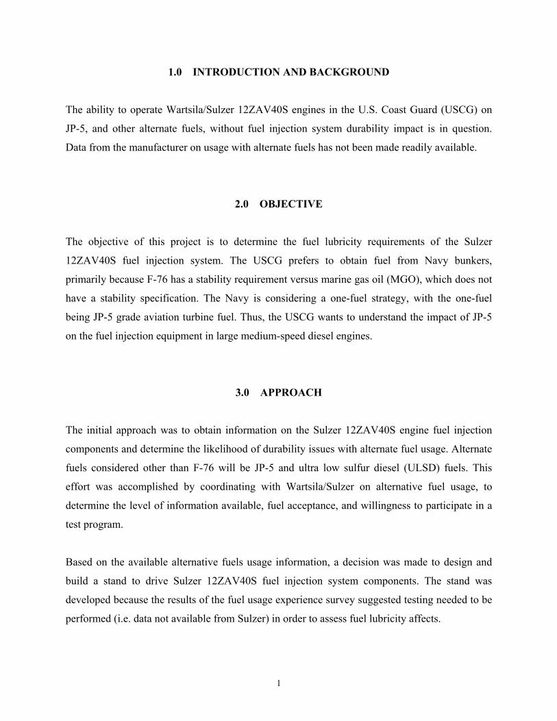
1.0 INTRODUCTION AND BACKGROUND
The ability to operate Wartsila/Sulzer 12ZAV40S engines in the U.S. Coast Guard (USCG) on
JP-5, and other alternate fuels, without fuel injection system durability impact is in question.
Data from the manufacturer on usage with alternate fuels has not been made readily available.
2.0 OBJECTIVE
The objective of this project is to determine the fuel lubricity requirements of the Sulzer
12ZAV40S fuel injection system. The USCG prefers to obtain fuel from Navy bunkers,
primarily because F-76 has a stability requirement versus marine gas oil (MGO), which does not
have a stability specification. The Navy is considering a one-fuel strategy, with the one-fuel
being JP-5 grade aviation turbine fuel. Thus, the USCG wants to understand the impact of JP-5
on the fuel injection equipment in large medium-speed diesel engines.
3.0 APPROACH
The initial approach was to obtain information on the Sulzer 12ZAV40S engine fuel injection
components and determine the likelihood of durability issues with alternate fuel usage. Alternate
fuels considered other than F-76 will be JP-5 and ultra low sulfur diesel (ULSD) fuels. This
effort was accomplished by coordinating with Wartsila/Sulzer on alternative fuel usage, to
determine the level of information available, fuel acceptance, and willingness to participate in a
test program.
Based on the available alternative fuels usage information, a decision was made to design and
build a stand to drive Sulzer 12ZAV40S fuel injection system components. The stand was
developed because the results of the fuel usage experience survey suggested testing needed to be
performed (i.e. data not available from Sulzer) in order to assess fuel lubricity affects.
2
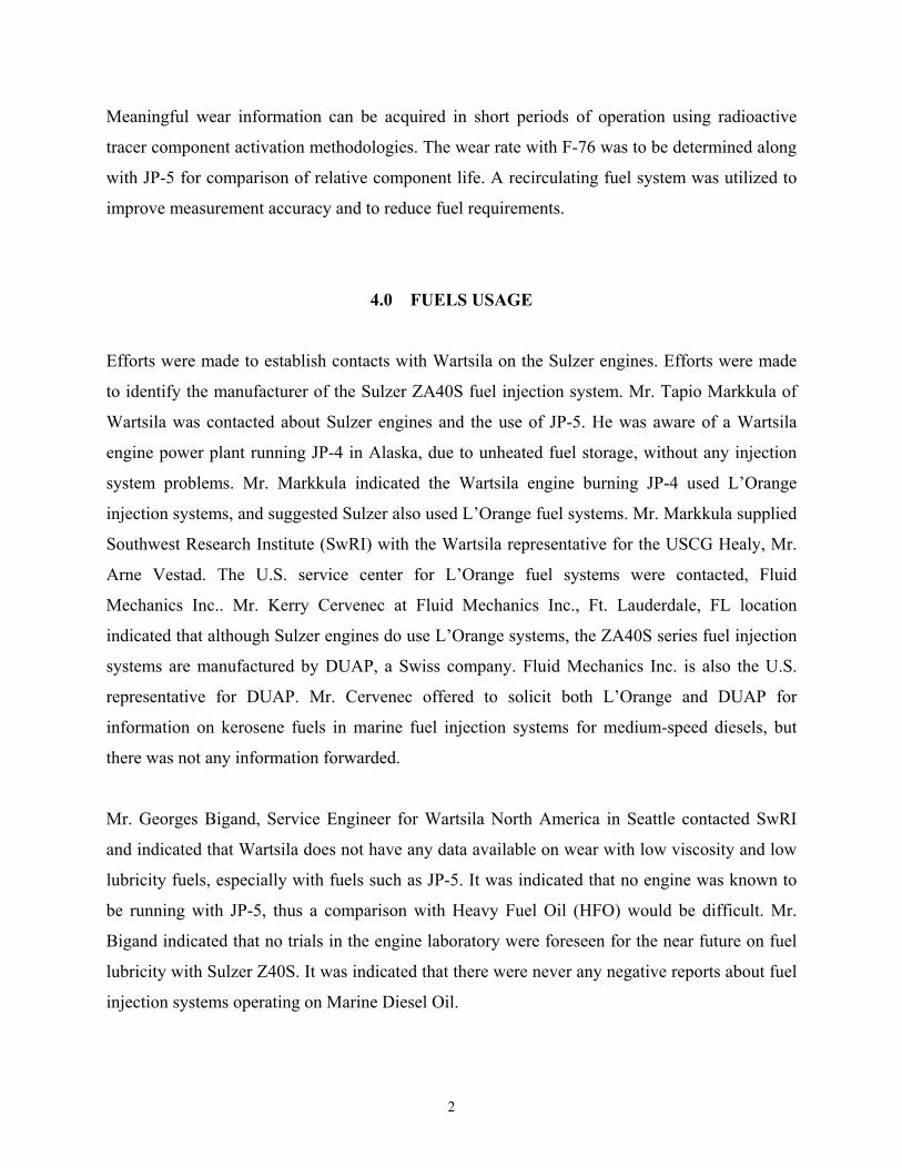
Meaningful wear information can be acquired in short periods of operation using radioactive
tracer component activation methodologies. The wear rate with F-76 was to be determined along
with JP-5 for comparison of relative component life. A recirculating fuel system was utilized to
improve measurement accuracy and to reduce fuel requirements.
4.0 FUELS USAGE
Efforts were made to establish contacts with Wartsila on the Sulzer engines. Efforts were made
to identify the manufacturer of the Sulzer ZA40S fuel injection system. Mr. Tapio Markkula of
Wartsila was contacted about Sulzer engines and the use of JP-5. He was aware of a Wartsila
engine power plant running JP-4 in Alaska, due to unheated fuel storage, without any injection
system problems. Mr. Markkula indicated the Wartsila engine burning JP-4 used L’Orange
injection systems, and suggested Sulzer also used L’Orange fuel systems. Mr. Markkula supplied
Southwest Research Institute (SwRI) with the Wartsila representative for the USCG Healy, Mr.
Arne Vestad. The U.S. service center for L’Orange fuel systems were contacted, Fluid
Mechanics Inc.. Mr. Kerry Cervenec at Fluid Mechanics Inc., Ft. Lauderdale, FL location
indicated that although Sulzer engines do use L’Orange systems, the ZA40S series fuel injection
systems are manufactured by DUAP, a Swiss company. Fluid Mechanics Inc. is also the U.S.
representative for DUAP. Mr. Cervenec offered to solicit both L’Orange and DUAP for
information on kerosene fuels in marine fuel injection systems for medium-speed diesels, but
there was not any information forwarded.
Mr. Georges Bigand, Service Engineer for Wartsila North America in Seattle contacted SwRI
and indicated that Wartsila does not have any data available on wear with low viscosity and low
lubricity fuels, especially with fuels such as JP-5. It was indicated that no engine was known to
be running with JP-5, thus a comparison with Heavy Fuel Oil (HFO) would be difficult. Mr.
Bigand indicated that no trials in the engine laboratory were foreseen for the near future on fuel
lubricity with Sulzer Z40S. It was indicated that there were never any negative reports about fuel
injection systems operating on Marine Diesel Oil.
3
The manufacturers of the Z40S fuel injection systems were confirmed to be both OMT and
DUAP. It was indicated that wear due to cavitation is possible if the fuel oil system is not
properly adjusted (1)*, but there were no worn components available for inspection at Seattle or
WCH (Wartsila Switzerland in Winterthur).
A Wartsila technical service manager in Italy indicated that attention should focus on the fuel
pump barrel and plunger clearance, which should preferably be smaller with kerosene fuels than
HFO engines. With the very low viscosity of JP-5, and the clearances for the plunger and barrel
calculated for HFO, one has to look at possible leakage down the plunger, which may induce
lubricating oil contamination with fuel.
SwRI has been following up with the Wartsila contacts for the Sulzer ZA40S engines and also
attempting to establish contacts with the fuel injection component manufacturers DUAP and
OMT. DUAP indicated good experience on other engines using critical fuels with coatings at the
injection pump plunger and the injection nozzle together with special heat treatment. Depending
on the results of testing, this could be an option for the Healy. DUAP indicated they could make
special test components if required.
5.0 FUEL INJECTION PUMP TEST FACILITY
The fuel injection pump test facility would require a cam support, camshaft components, and fuel
injection system components. Due to the low rpm, large injection quantities, and high injection
pressure a sizeable flywheel was required to operate the cambox. A flywheel is required to
minimize the speed variations of the injection cam during the injection event. Preliminary
calculations suggest 15-hp will be required to inject the fuel for one injector. More accurate
injection pressure and delivery data was obtained to refine the cam box design.
The drive system for the injection pump was designed. A motoring dynamometer with an
electromagnetic clutch was to be used to drive the injection system. The clutch and drive system
was verified to operate with stability and controllably at 257 rpm, the expected Sulzer engine
4
fuel injection pump speed. Injection system data was reviewed and it was determined a single
flywheel of appropriate mass, shafts, and flywheel support bearings taken from a single cylinder
engine crankcase would provide the requisite inertia. It was calculated the single cylinder
crankcase crankshaft support bearings would support the Sulzer fuel cam with a sufficient safety
factor. Modifications to the crankcase to mount the injection pump were determined from cam
dimensions provided by Wartsila. The test cell stand was configured and modified for the
flywheel, bearings, and shafts and the coupling between the motoring dynamometer and injection
stand was machined.
The engine technical manuals were received, along with engine serial numbers, to determine
component part designations (2,3,4,5,6,7). Information obtained from the engine tech manuals
was used to layout the design of the test stand and the test loop fuel system. A source of engine
components was located, and quotes for parts obtained. A Wartsila representative supplied the
Healy component designations in order to obtain the most current parts. The fuel injection parts
as installed on the Healy are shown in Table 1. The fuel injection parts as installed on the Healy
were used to issue a purchase requisition.
Table 1. Healy Main Engine Injection Specification
740386 740387 740388 740389
Injectors 144o X 10 X 0 650
144o X 10 X 0 650
144o X 10 X 0 650
144 o X 10 X 0 650
Originaly i t ll d
Fuel Delivery Pipe (i
Ø) 6 mm 6 mm 6 mm 6 mm
Barrel/Plonger h
C.I.T* C.I.T* C.I.T * C.I.T*
Effective Delivery t k
14.73 mm 14.73 mm 14.73 mm 14.73 mm
Injectors 160o X 13 X 0.60 160o X 13 X 0.60 160o X 13 X 0.60 160 o X 13 X 0.60
Present i t ll ti
Fuel Delivery Pi
7 mm 7 mm 7 mm 7 mm
Barrel/Plunger h
VD 2** C.I.T* VD 2** VD 2**
Effective Delivery t k
14.73 mm 14.73 mm 14.73 mm 14.73 mm
Engine N b
* C.I.T : Constant Injection Ti i** VD 2 : Variable Damping 2nd
ti
Healy Main Engine Injection Specification
5
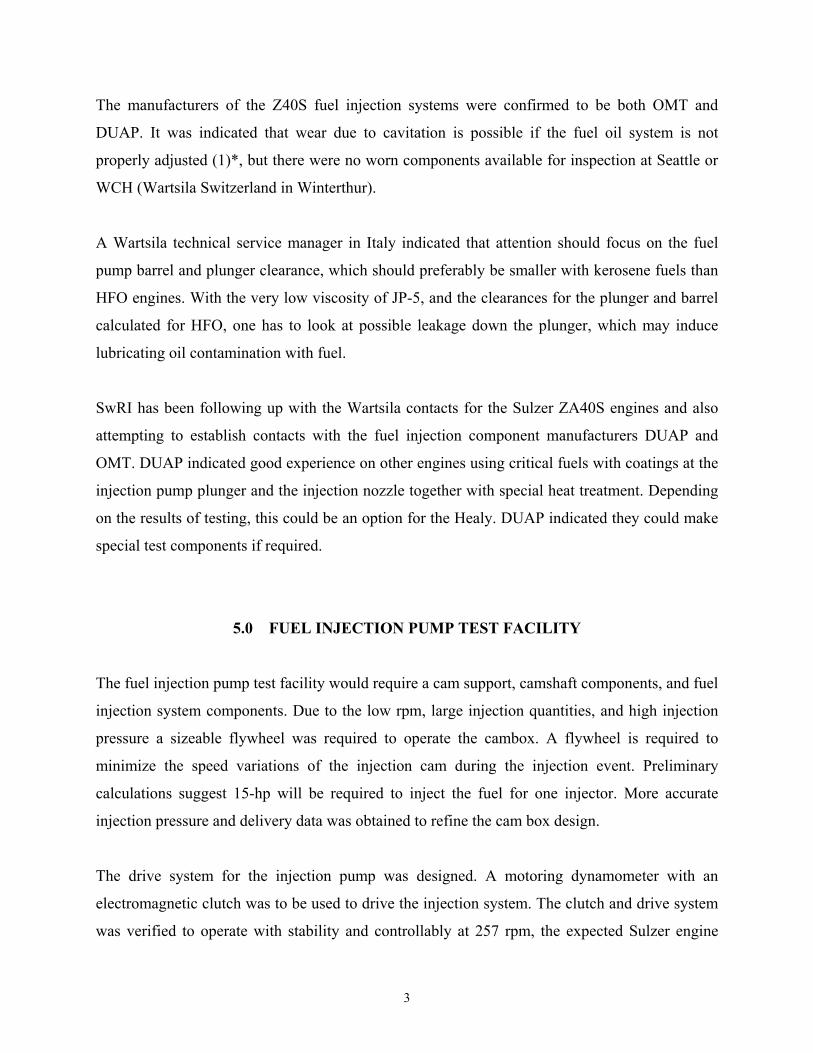
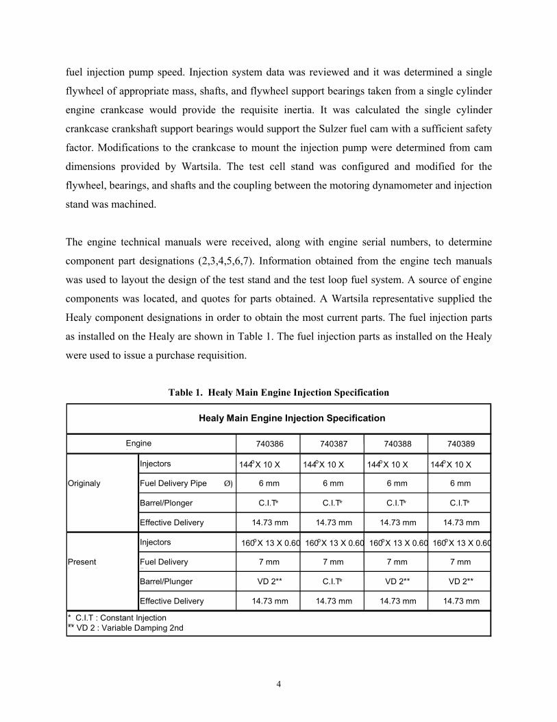
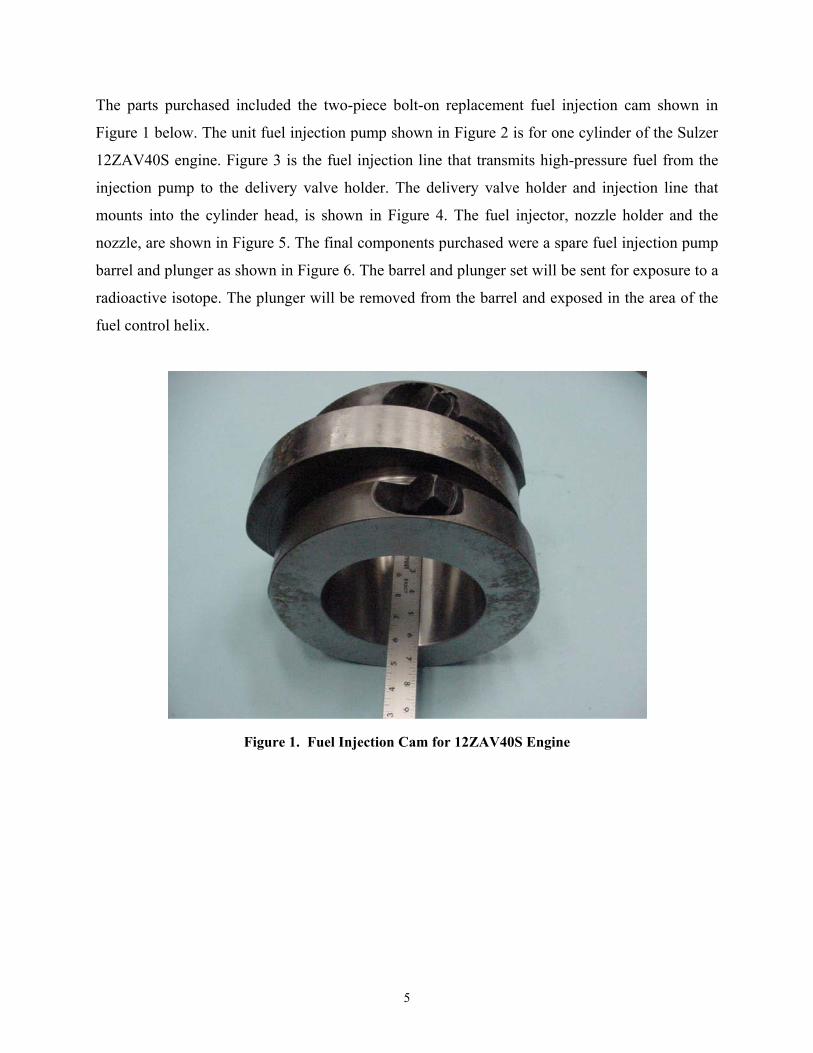
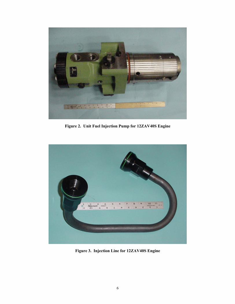
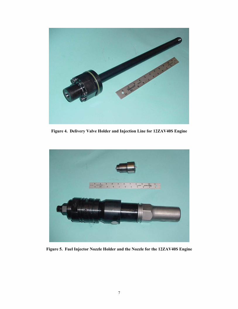
The parts purchased included the two-piece bolt-on replacement fuel injection cam shown in
Figure 1 below. The unit fuel injection pump shown in Figure 2 is for one cylinder of the Sulzer
12ZAV40S engine. Figure 3 is the fuel injection line that transmits high-pressure fuel from the
injection pump to the delivery valve holder. The delivery valve holder and injection line that
mounts into the cylinder head, is shown in Figure 4. The fuel injector, nozzle holder and the
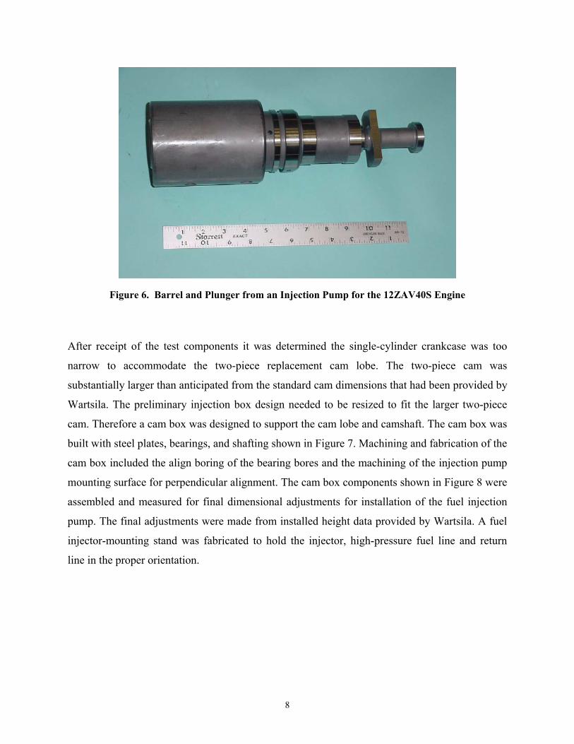
nozzle, are shown in Figure 5. The final components purchased were a spare fuel injection pump
barrel and plunger as shown in Figure 6. The barrel and plunger set will be sent for exposure to a
radioactive isotope. The plunger will be removed from the barrel and exposed in the area of the
fuel control helix.
Figure 1. Fuel Injection Cam for 12ZAV40S Engine
6
Figure 2. Unit Fuel Injection Pump for 12ZAV40S Engine
Figure 3. Injection Line for 12ZAV40S Engine
7
Figure 4. Delivery Valve Holder and Injection Line for 12ZAV40S Engine
Figure 5. Fuel Injector Nozzle Holder and the Nozzle for the 12ZAV40S Engine
8
Figure 6. Barrel and Plunger from an Injection Pump for the 12ZAV40S Engine
After receipt of the test components it was determined the single-cylinder crankcase was too
narrow to accommodate the two-piece replacement cam lobe. The two-piece cam was
substantially larger than anticipated from the standard cam dimensions that had been provided by
Wartsila. The preliminary injection box design needed to be resized to fit the larger two-piece
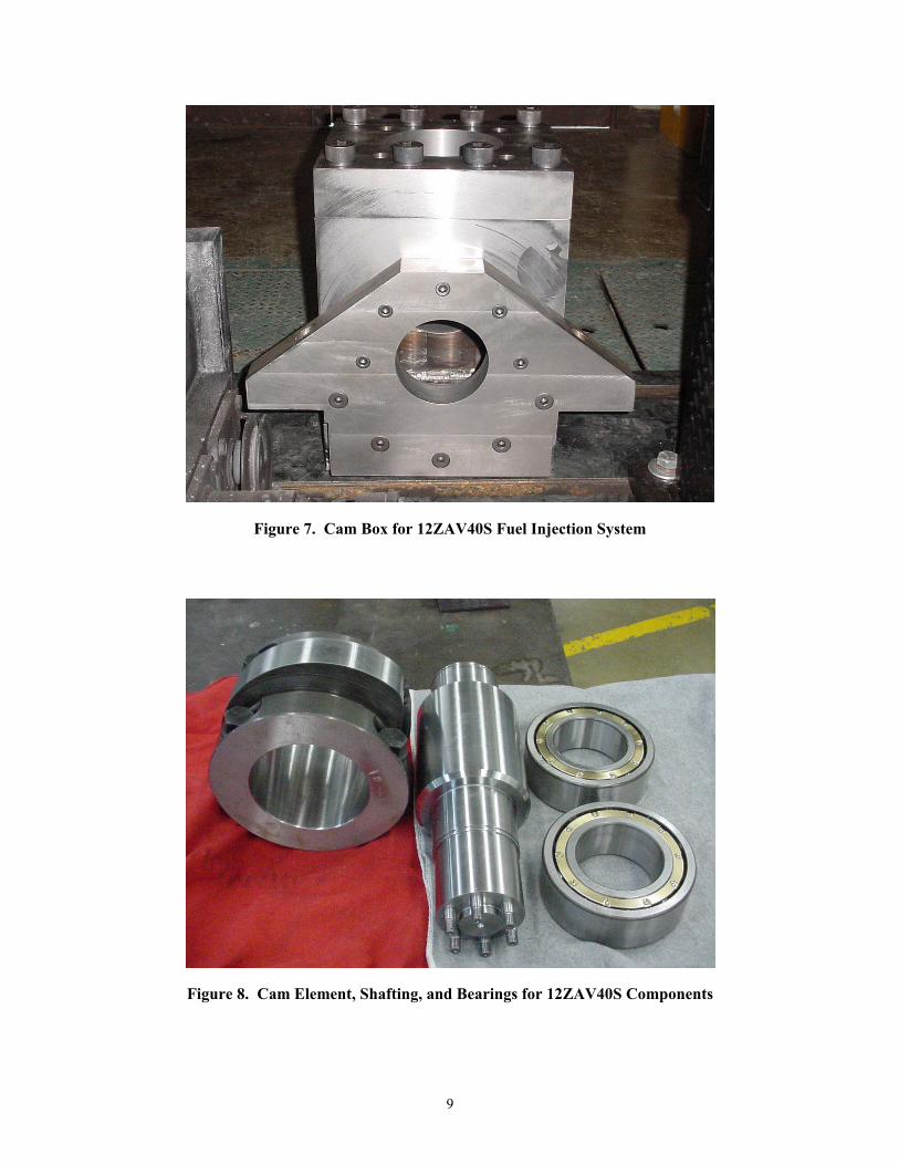
cam. Therefore a cam box was designed to support the cam lobe and camshaft. The cam box was
built with steel plates, bearings, and shafting shown in Figure 7. Machining and fabrication of the
cam box included the align boring of the bearing bores and the machining of the injection pump
mounting surface for perpendicular alignment. The cam box components shown in Figure 8 were
assembled and measured for final dimensional adjustments for installation of the fuel injection
pump. The final adjustments were made from installed height data provided by Wartsila. A fuel
injector-mounting stand was fabricated to hold the injector, high-pressure fuel line and return
line in the proper orientation.
9
Figure 7. Cam Box for 12ZAV40S Fuel Injection System
Figure 8. Cam Element, Shafting, and Bearings for 12ZAV40S Components
10
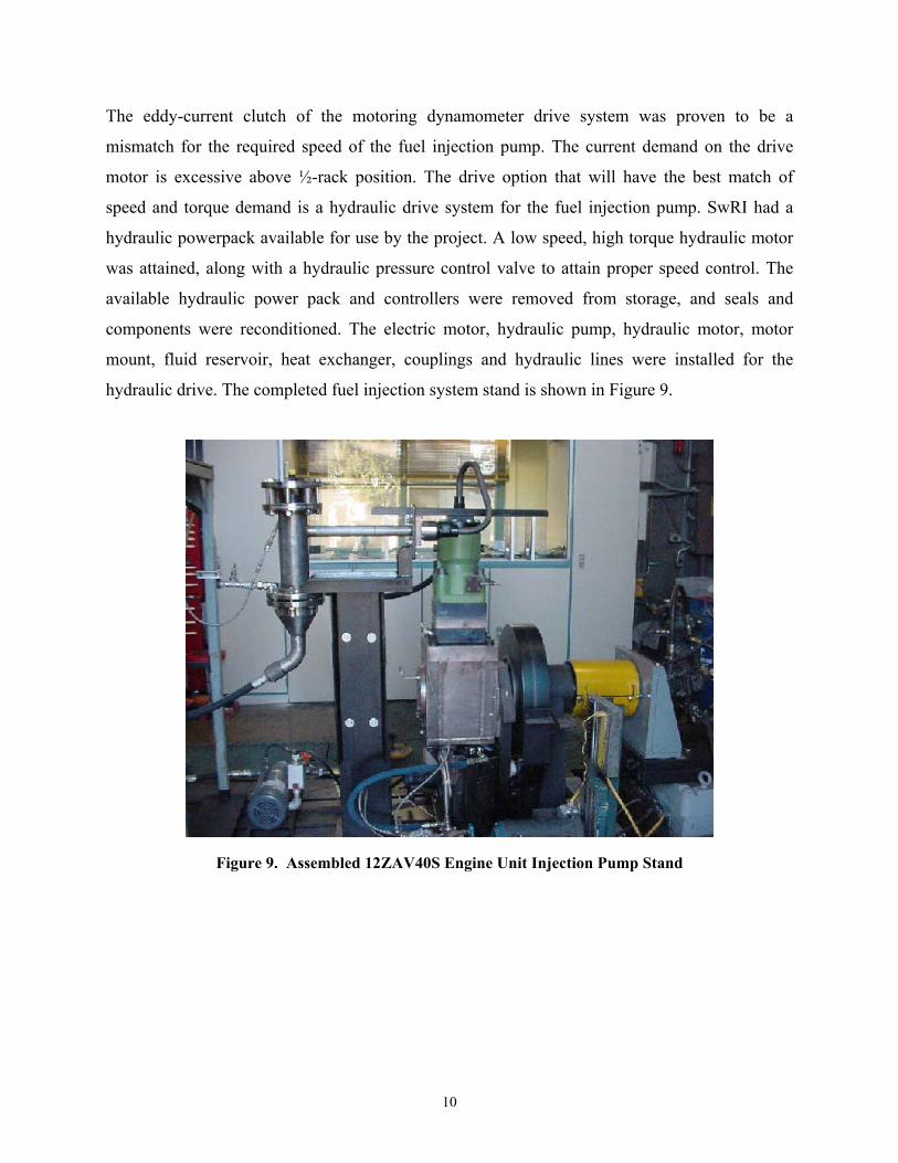
The eddy-current clutch of the motoring dynamometer drive system was proven to be a
mismatch for the required speed of the fuel injection pump. The current demand on the drive
motor is excessive above ½-rack position. The drive option that will have the best match of
speed and torque demand is a hydraulic drive system for the fuel injection pump. SwRI had a
hydraulic powerpack available for use by the project. A low speed, high torque hydraulic motor
was attained, along with a hydraulic pressure control valve to attain proper speed control. The
available hydraulic power pack and controllers were removed from storage, and seals and
components were reconditioned. The electric motor, hydraulic pump, hydraulic motor, motor
mount, fluid reservoir, heat exchanger, couplings and hydraulic lines were installed for the
hydraulic drive. The completed fuel injection system stand is shown in Figure 9.
Figure 9. Assembled 12ZAV40S Engine Unit Injection Pump Stand
11
6.0 RADIOACTIVE TRACER EXPERIMENTAL DESIGN
A test program was outlined for radioactive tracer wear measurements. The test program was to
establish a break-in level with Diesel Fuel Marine (DFM), than perform wear rate measurements
with DFM, followed by JP-5. The wear rates for JP-5 and DFM were to be repeated several
times to establish consistency and statistical information. The fluid test loop was designed using
injector flows and bypass rates at the rated operating condition to finalize the test loop design.
Preliminary calculations suggest that because of the anticipated low wear rates and the desire to
obtain measurable wear debris signal in the test fluid, a bulk activation technique would not be
appropriate. The anticipated in-service life of the fuel injection' components are 24,000 hours per
the Technical Manual. A contact was established with DUAP, an injection component supplier
for the ZA40S series engines. The injection pressure of this engine is about 1200 bar and the
injection pump plunger has a diameter of 35 mm and a delivery stroke of 15.9 mm. At this size,
the Surface Layer Activation (SLA) radioactive tracer method is the only safe method to use.
The most critical components reported during operation with low viscosity and/or high corrosive
fuels are the injection pump plunger with cylinder and the injection nozzle shaft. Due to the size
of the ZA40S components, bulk activation would result in components that are radioactively too
contaminated to be handled safely within human exposure limits.
SLA techniques were required. The SLA technique radiates a small area, a few microns deep,
then monitors the reduction in activity as the part wears. SLA requires knowledge of the location
of greatest wear, so the component can be activated in that area. The area of wear of the injection
components was sought from the component manufacturers to improve credibility of the wear
data generated. SLA also requires a detailed calibration procedure that establishes the material
removal versus activity curve. The SLA test procedures were outlined, and resources for
activation and calibration established.
The activation design is proved to be a challenge due to the mass of metal that shields the
detector from the activated injection plunger. Current thought is a shallow grazing angle will be
required for the activation to get the measurement sensitivity needed. However a shallow grazing
angle is also affected by the surface finish. Surface finish was determined and estimates were
12
made to determine the activation profile needed to provide reasonable wear resolution within
several hours of operation. The activation of the components took place after the cam box was
completed and the injection pump and fuel system were operational so that the test components
could be run-in.
SLA works by developing a master calibration curve of radiation versus material removal.
Because of the cost of the components, a test coupon was used to develop the calibration curve.
DUAP had supplied the designation of the fuel injection pump plunger alloy. SwRI received a
report from Chuck Blatchley at Pittsburg State University describing the results for a trial
activation. They bombarded four samples with 6 MeV protons at an incidence angle of 60°. They
then performed depth calibration measurements using a polishing technique to produce curves of
activity as a function of depth. Based upon these curves, they developed a fourth order
polynomial equation describing wear as a function of counting rate. They also measured the
isotope production rate of the activation. SwRI believes that 10 microcuries of Co-56 are needed
within 7 µm of the surface to accurately make this measurement. Although the activation depth
was right on target, the production rate achieved by Pittsburg state was not sufficient to
reasonably produce this much activity (8).
As an alternative, SwRI approached Ken Oxorn of ANS Technologies in Montreal, Canada to
perform the activation. SwRI had worked with ANS Technologies in the past and believed he
can perform a reliable activation. Rather than perform a physical depth calibration, Ken uses a
theoretical model to determine relative activity as a function of depth. Based upon his experience
he has good confidence the model will be within 2% of the actual activation.
In addition, ANS Technologies had agreed to perform a trial activation at their cost to validate
the equipment setup, masking scheme and production rate. SwRI had sent the spare Sulzer
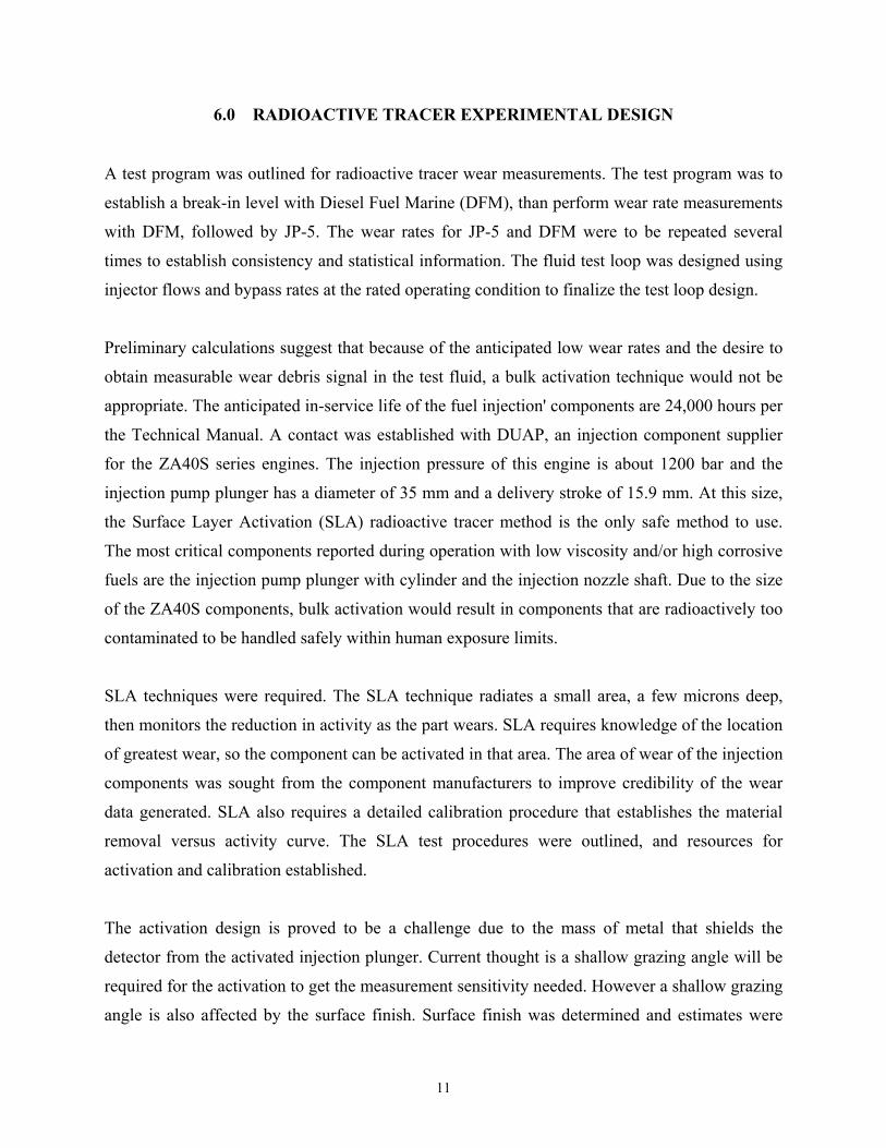
plunger to ANS for this activation. The plunger manufacturer DUAP supplied a sketch
(Figure 10) of two characteristic wear areas on the fuel injection pump plunger. One wear area
was at mid-stroke on the plunger most likely where maximum fuel injection pressure is
developed. ANS made a tantalum mask for the plunger in the area designated by SwRI for the
trial activation. The activation was performed and the preliminary results indicated the masking
and production rates were satisfactory.
13
Figure 10. Sketch from DUAP on Plunger Wear Areas
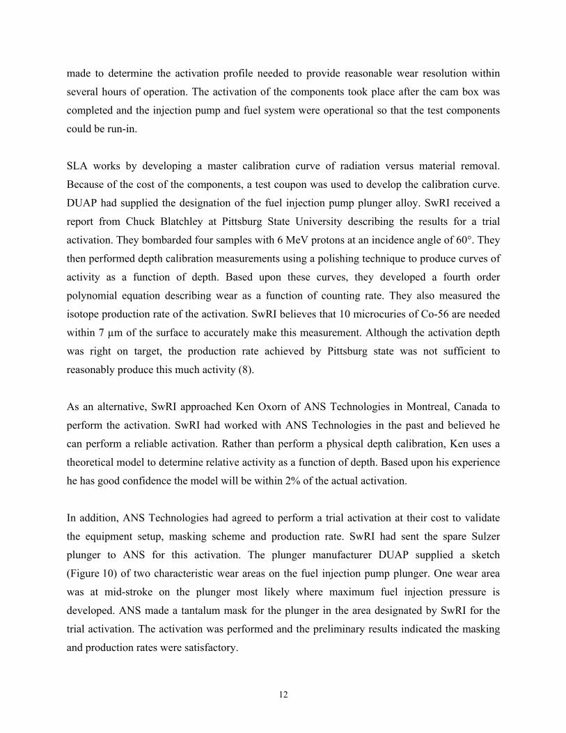
The activation of the test components took place after the fuel injection pump was operated for
20 hours to run-in the wear surfaces using a 3000-g lubricity level fuel. The included figures
show radiographs of the plunger intended for wear testing and the plunger used for the trial
activation. The intention was to activate two areas on the plunger, 180 degrees apart, with about
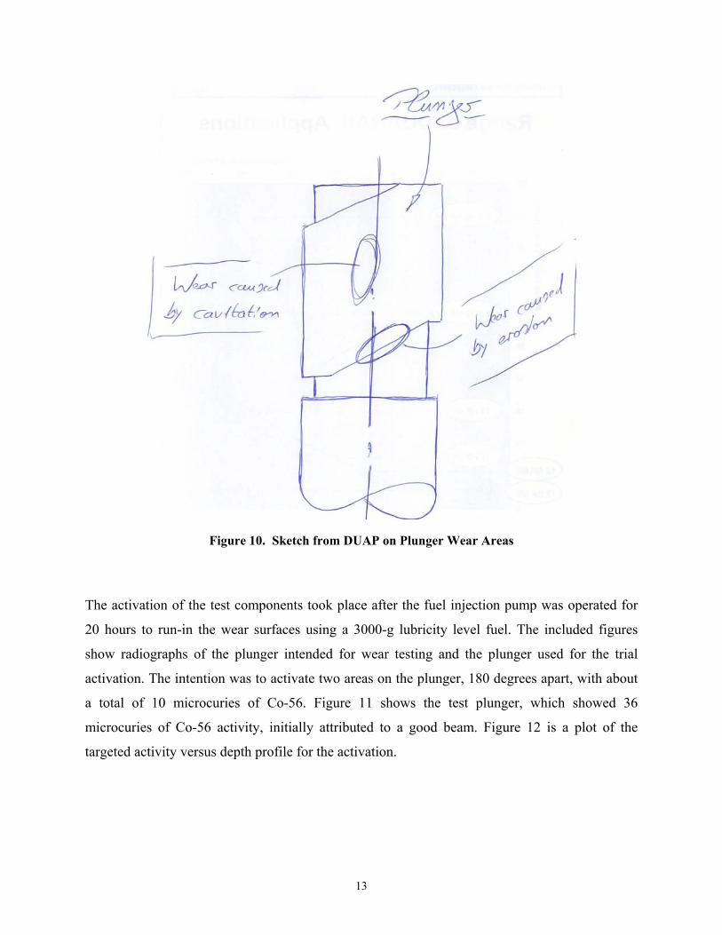
a total of 10 microcuries of Co-56. Figure 11 shows the test plunger, which showed 36
microcuries of Co-56 activity, initially attributed to a good beam. Figure 12 is a plot of the
targeted activity versus depth profile for the activation.
14
Targeted Area
Unintended Beam Strike
Figure 11. Radiograph Showing Target Area and Unintentional Activation
Figure 12. Activity Versus Depth Profile for Co-56
15
Examination of the radiograph indicates the activity is high because the beam struck an
unmasked vertical edge of the plunger. It is likely most of the activity measured is on the vertical
surface, normal to any wear surface. Figure 11 does show activity in the target area, but SwRI
cannot separate the activity from that area with the detectors. Furthermore, the activity depth
profile is unknown due to the beam strikes on the different surfaces. It appears the mask was not
extended far enough along the length of the plunger to block the beam from an unintentional
strike (9). The subcontractor acknowledged their error, and will activate another plunger at no cost.
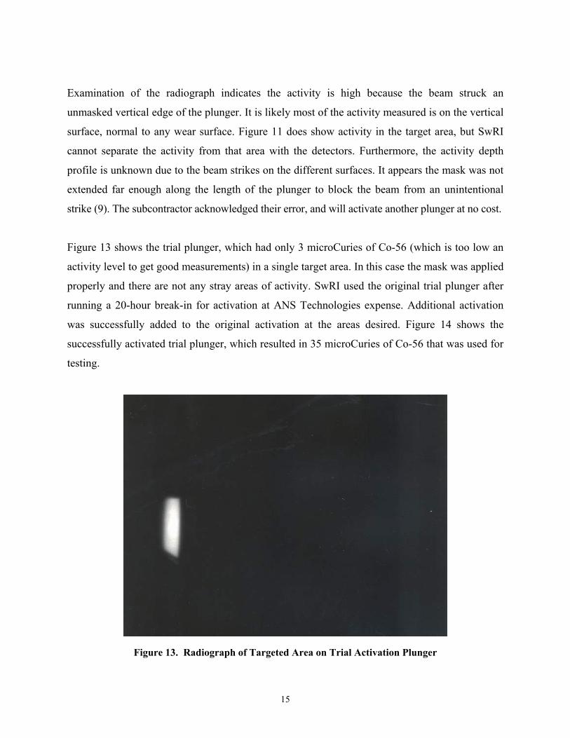
Figure 13 shows the trial plunger, which had only 3 microCuries of Co-56 (which is too low an
activity level to get good measurements) in a single target area. In this case the mask was applied
properly and there are not any stray areas of activity. SwRI used the original trial plunger after
running a 20-hour break-in for activation at ANS Technologies expense. Additional activation
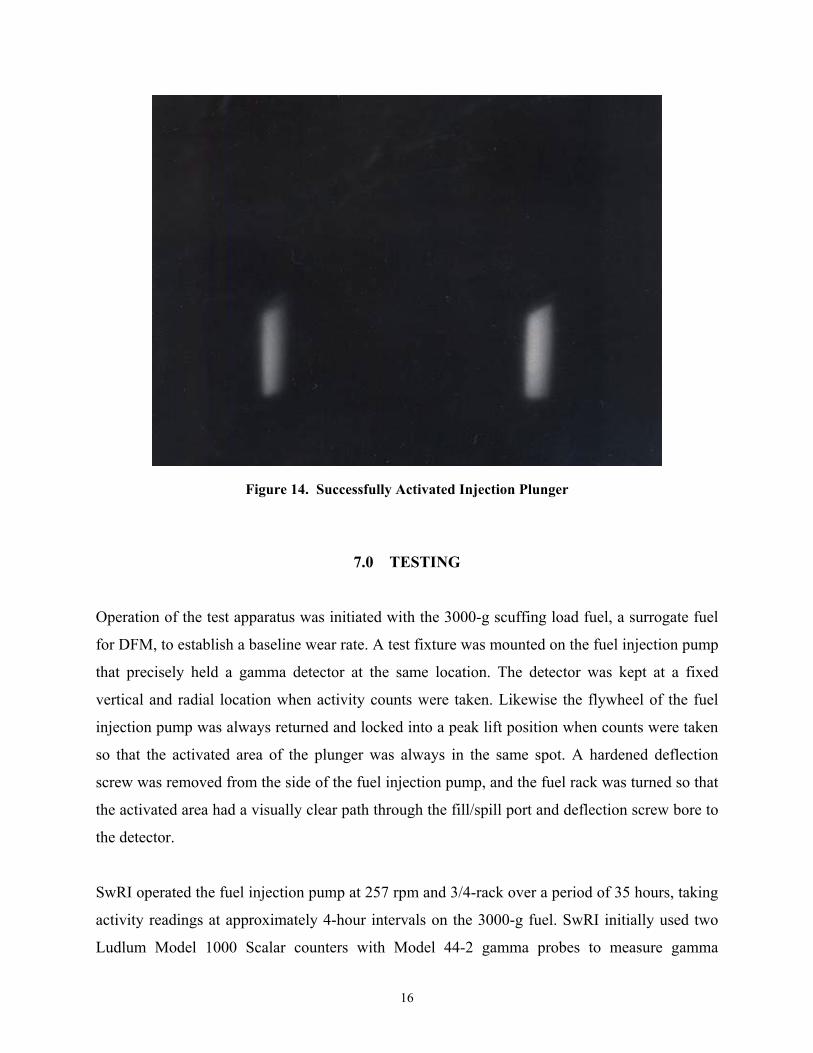
was successfully added to the original activation at the areas desired. Figure 14 shows the
successfully activated trial plunger, which resulted in 35 microCuries of Co-56 that was used for
testing.
Figure 13. Radiograph of Targeted Area on Trial Activation Plunger
16
Figure 14. Successfully Activated Injection Plunger
7.0 TESTING
Operation of the test apparatus was initiated with the 3000-g scuffing load fuel, a surrogate fuel
for DFM, to establish a baseline wear rate. A test fixture was mounted on the fuel injection pump
that precisely held a gamma detector at the same location. The detector was kept at a fixed
vertical and radial location when activity counts were taken. Likewise the flywheel of the fuel
injection pump was always returned and locked into a peak lift position when counts were taken
so that the activated area of the plunger was always in the same spot. A hardened deflection
screw was removed from the side of the fuel injection pump, and the fuel rack was turned so that
the activated area had a visually clear path through the fill/spill port and deflection screw bore to
the detector.
SwRI operated the fuel injection pump at 257 rpm and 3/4-rack over a period of 35 hours, taking
activity readings at approximately 4-hour intervals on the 3000-g fuel. SwRI initially used two
Ludlum Model 1000 Scalar counters with Model 44-2 gamma probes to measure gamma
17
emissions from the test plunger. The initial test protocol was to take a series of ten 1-minute
measurements on a background, a reference, the test article and a reference repeat. It was known
that these detectors have a temperature dependant drift. The initial plan was to use the reference
measurements to correct for this drift. As a reference, SwRI used the plunger that had been
irradiated in the wrong spot.
Subsequent testing revealed that the reference measurements obtained were not constant, thus
making the test plunger measurements unreliable. Suspecting a problem with the Ludlum gamma
probes, a switch was made to a three inch NaI detector with a computerized spectroscopy
system. This allowed viewing counts as a function of energy. Initially the detector was set up on
the reference plunger. When the detector was put in the vicinity of the test article, however, the
energy peaks shifted significantly. Investigation revealed that the NaI gamma probes are
sensitive to magnetic fields. Measurements made around the injection pump assembly with a
magnetometer that revealed the presence of a magnetic field. This magnetic field likely changes
over time, resulting in sensitivity shifts in the radiation detection equipment.
SwRI fabricated a magnetic shield for the detector and initial tests revealed that this stopped the
energy peak shifts when the detector was put near the test article. The detector was set up to
count one-minute samples over a weekend and recorded a slow period drift that followed outdoor
temperature. Though the reference measurements could be used to correct for this, SwRI felt that
a temperature control system could be implemented to minimize this drift and get more
consistent measurements. A temperature control system was added and one-minute counts were
taken overnight. The overnight measurements proved stable.
Unfortunately data from the 35-hour operation was unusable because it could not be corrected
for the magnetic interference. Efforts to mitigate the effects of the magnetic fields and
temperature initially appeared to have been successful. SwRI continued measuring the change in
activity of the plunger as a function of operating hours. Between 35 and 47 hours the
measurement remained nearly constant, following decay correction. This indicated that the
plunger was not wearing sufficiently for us to detect a change over this period. The fuel was
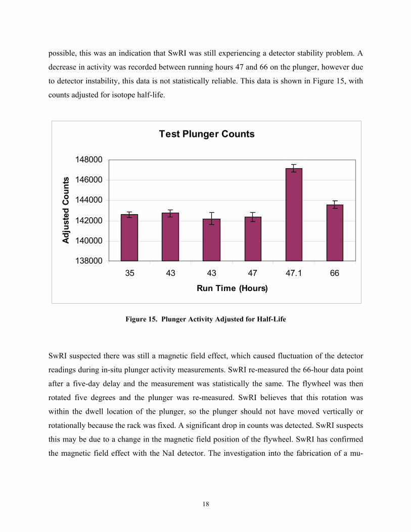
changed and a significant increase in plunger activity was measured. Since this is not physically
18
possible, this was an indication that SwRI was still experiencing a detector stability problem. A
decrease in activity was recorded between running hours 47 and 66 on the plunger, however due
to detector instability, this data is not statistically reliable. This data is shown in Figure 15, with
counts adjusted for isotope half-life.
Test Plunger Counts
138000
140000
142000
144000
146000
148000
35 43 43 47 47.1 66
Run Time (Hours)
Adju
sted
Cou
nts
Figure 15. Plunger Activity Adjusted for Half-Life
SwRI suspected there was still a magnetic field effect, which caused fluctuation of the detector
readings during in-situ plunger activity measurements. SwRI re-measured the 66-hour data point
after a five-day delay and the measurement was statistically the same. The flywheel was then
rotated five degrees and the plunger was re-measured. SwRI believes that this rotation was
within the dwell location of the plunger, so the plunger should not have moved vertically or
rotationally because the rack was fixed. A significant drop in counts was detected. SwRI suspects
this may be due to a change in the magnetic field position of the flywheel. SwRI has confirmed
the magnetic field effect with the NaI detector. The investigation into the fabrication of a mu-
19
metal shield to eliminate the magnetic field effects resulted in data that could not be used with
confidence.
The best approach for stable in-situ measurements would be to setup and calibrate a germanium
detector. It would require setting up a detector and a liquid nitrogen dewar on a table to get it as
close to the plunger as physically possible. The difficulty is locating it in a position where it will
not be moved at all. This would be very difficult given the level of pounding when the system is
running. It will also need vibration damping to protect the crystal. Though SwRI won't be
running the germanium detector while the rig is running, SwRI doesn't think it can be moved
while running and repositioned accurately like was done with the NaI detector.
There were not sufficient funds remaining to further pursue in-situ activity measurements. A
cost-effective option for the project was to remove the plunger from the pump and take it to a lab
fixture for activity measurement. SwRI fabricated a jig for accurate positioning. Unfortunately
there was not a baseline established previously with the germanium detector. The plan was to
remove the plunger, measure for activity, replace the plunger, operate the injection pump on the
fuel 3000, and then remove the plunger again for re-measurement. If this proved successful, the
process would be repeated with the 2000-g scuffing load fuel.
The base 3000-g scuffing fuel had degraded which resulted in improved fuel lubricity (scuffing
load value increased). This fuel batch was also the base fuel for a Navy lubricity program, and
insufficient quantity existed for both programs. A replacement batch of base fuel was sought;
therefore, testing was initiated with the 2000-g scuffing fuel. The injection rig was de-fueled,
cleaned, and flushed prior to filling with the 2000-g fuel. The pump cambox was inspected, the
cambox oil changed, and the hydraulic drive system checked. An additional set of activity
measurements was taken on the plunger prior to re-assembly of the injection pump. The injection
pump has been reassembled and the cleaned and flushed fuel system filled with the 2000-g fuel.
The pump and drive were checked for proper operation.
The fuel injection rig was operated for 12 hours and then shut down to check the activity of the
plunger. The activity measurements, when corrected for decay suggest that 12 hours of operation
20
did not result in any detectable activity loss on the plunger. At the end of twelve hours a
discoloration was noted in the test fuel. The 2000-g fuel is water white to pale yellow, and a light
gray to brown tinge was noted. It was felt lubricating oil could be migrating into the metering
section of the pump and being injected. Due to the recirculating fuel system, this meant lube oil
could accumulate in the fuel supply and improve the fuel lubricity and skew results. A fuel
sample was filtered, and the filter residue was examined by x-ray for elemental content. If the
contaminant were lube oil, the additive metals would be revealed in certain proportions. The
elemental analysis indicated the contaminant was fuel degradation products, most likely from the
previous 3000-g fuel. The fuel system was drained and significant effort was extended to clean
the system by swabbing all fuel lines and reservoirs with isooctane.
The injection stand was reassembled after 36 hours of operation, and charged with a new batch
of 2000-g fuel to continue testing. A corrosion inhibitor additive was added to the fuel to make
the fuel more similar to JP-5. Again, after several hours of operation fuel discoloration was
apparent. It was believed the contaminant was lubricating oil migrating up from the bottom end
of the injection pump. The bottom end of the injection pump is supplied lubricating oil as is the
engine, and at the oil pressure prescribed for the engine. A sample of the test fuel was checked
for lubricity, both in the tank volume and the injector effluent.
The high-frequency reciprocating rig (HFRR) lubricity result for the tank was 643-microns and
for the injector effluent was 583-microns wear scar diameter. Based on lab repeatability at SwRI
these results suggest an improvement of the fuel lubricity due to lubricating oil migrating into the
injection pump. However, lubricity results of both fuels indicate they are still low lubricity fuels,
with the generally accepted range for a good lubricity fuel being 460 to 520-microns wear scar
diameter. Combined with the low viscosity of the 2000-g fuel, it is felt the fuel injection
equipment is still being challenged with a fairly severe fuel. The test rig was operated for 72 total
hours with the activity of the injection pump plunger checked at 12, 24, 36, and then 72 hours.
The fuel was changed at 36 hours as noted. Correcting for half-life, there was not any measurable
wear detected with the 2000-g fuel. The injection pump wear results on the 2000-g fuel, which
were below 0.14-microns of total wear, suggests that the use of JP-5 should not impact vessel
operations.
21
Initial thought was to try the 1000-g fuel and see if measurable wear would be evident with this
type of poor lubricity fuel. However, SwRI recently ran the 1000-g fuel in two different systems
that resulted in rapid seizures of the injection pumps. SwRI became hesitant to put the fuel in the
Sulzer system for fear of seizing the injection pump; the concern being that the 1000-g fuel has
both extremely low lubricity and low viscosity, and being in the kerosene boiling range. The
resulting question is how likely would it be that a Fischer-Tropsch fuel would be available to the
Coast Guard as a JP-5 versus a DFM? Fischer-Tropsch DFM would be the logical choice
because it would meet all ULSD specifications, would have zero aromatics, and would have a
higher viscosity.
Although there were some problems with the on-line detection with detector stability while
running the 3000-g fuel, it was apparent wear was not seen with that fuel and compounded the
problem. This fact was verified by the lack of wear detected with the 2000-g fuel. The 2000-g
fuel was additive treated to make it a true JP-5 to answer the Coast Guard JP-5 question directly
(i.e., Is JP-5 OK?).
It was decided to continue with the 2000-g + additive, or JP-5 fuel, for an additional 72 hours to
determine if wear can be detected. Wear would be detected when it exceeds the detection limits
imposed by the activation profile and instrumentation. If wear is detected the units would be
microns of material removed, and would be reported as micron/hour wear rate. The DCI-4A
additive improved the scuffing load of the neat 2000-g fuel to around 2825-g scuffing load. Of
interest was the HFRR result for the fuel, which was 645-micron wear scar diameter (WSD), a
result that reveals a poor HFRR sensitivity to additives in small quantities.
22
Several samples of fuel and the lubricating oil were sent for elemental analysis. These samples
included fuel directly from the injector, fuel from the 40-gallon fuel reservoir, fuel/oil mix from
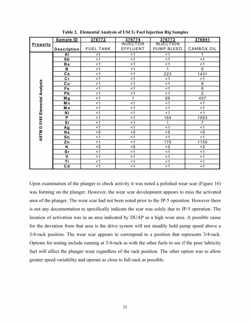
the injection pump bleed, and a sample of the lubricating oil from the cam box. Table 2 shows
the results of the elemental analysis of the samples in units of parts-per-million (ppm). The
cambox lubricating oil shows large concentrations of additive elements that were to be used as
tracer elements in the fuel. The injector effluent and fuel tank samples did not reveal any additive
metal above the detection limit of the instrument and test method, ASTM D 5185. To put the
results in perspective, if 1-ppm Ca did exist in the fuel, based on the lube oil Ca level, the overall
concentration of lube oil in the fuel would be around 70-ppm. Most surface-active additive
elements are put into fuels at the 10 to 20-ppm levels. Data reported by SwRI in Letter Report
No. BFLRF-91-007 (10) shows that lubricating oils in fuels are not effective as a lubricity
improver unless the concentrations are above 0.5% (5000 ppm). Although the color of our test
fuel indicates a contaminant, the elemental analysis, and data from previous studies suggest the
contamination is not significant enough to alter the lubricity of the test fuel. Both Wartsila and
DUAP were contacted to ascertain the possibility of lubricant migration into the metering section
of the pump. Neither company has responded to the requests for information. The injection pump
bleed data indicates a fuel and oil mix in the injection pump at about 7 parts fuel to 1 part oil
based on the calcium (Ca) results.
Both Wartsila and DUAP were contacted to ascertain the possibility of lubricant migration into
the metering section of the pump. DUAP had not responded to the requests for information.
Wartsila sent information pertaining to how the injection pump design is intended to separate
fuel and oil. It is not entirely clear from the Wartsila text if the potential for lube oil
contamination in the injected fuel is possible. However as noted, the level of contaminant from
lube oil was very low, verified by lube oil element tracer, and previous work at SwRI indicated
percentage levels of lubricant was needed in a fuel before lubricity changed.
23
Table 2. Elemental Analysis of USCG Fuel Injection Rig Samples
Sam ple ID 376772 376774 376773 376941
Description FUEL TANKINJECTOR EFFLUENT
INJECTION PUMP BLEED CAMBOX OIL
Al <1 <1 <1 1Sb <1 <1 <1 <1Ba <1 <1 <1 <1B <1 <1 1 6
Ca <1 <1 223 1431Cr <1 <1 <1 <1Cu <1 <1 <1 8Fe <1 <1 <1 6Pb <1 <1 <1 2M g <1 1 69 457M n <1 <1 <1 <1M o <1 <1 <1 <1Ni <1 <1 <1 <1P <1 <1 164 1063Si <1 <1 1 7Ag <1 <1 <1 <1Na <5 <5 <5 <5Sn <1 <1 <1 <1Zn <1 <1 175 1150K <5 <5 <5 <5Sr <1 <1 <1 <1V <1 <1 <1 <1Ti <1 <1 <1 <1Cd <1 <1 <1 <1
AST
M D
518
5 El
emen
tal A
naly
sis
Property
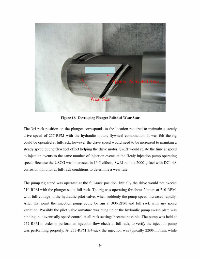
Upon examination of the plunger to check activity it was noted a polished wear scar (Figure 16)
was forming on the plunger. However, the wear scar development appears to miss the activated
area of the plunger. The wear scar had not been noted prior to the JP-5 operation. However there
is not any documentation to specifically indicate the scar was solely due to JP-5 operation. The
location of activation was in an area indicated by DUAP as a high wear area. A possible cause
for the deviation from that area is the drive system will not steadily hold pump speed above a
3/4-rack position. The wear scar appears to correspond to a position that represents 3/4-rack.
Options for testing include running at 3/4-rack as with the other fuels to see if the poor lubricity
fuel will affect the plunger wear regardless of the rack position. The other option was to allow
greater speed variability and operate as close to full-rack as possible.
24
Wear Scar
Approx. Activated Area
Figure 16. Developing Plunger Polished Wear Scar
The 3/4-rack position on the plunger corresponds to the location required to maintain a steady
drive speed of 257-RPM with the hydraulic motor, flywheel combination. It was felt the rig
could be operated at full-rack, however the drive speed would need to be increased to maintain a
steady speed due to flywheel effect helping the drive motor. SwRI would relate the time at speed
to injection events to the same number of injection events at the Healy injection pump operating
speed. Because the USCG was interested in JP-5 effects, SwRI ran the 2000-g fuel with DCI-4A
corrosion inhibitor at full-rack conditions to determine a wear rate.
The pump rig stand was operated at the full-rack position. Initially the drive would not exceed
210-RPM with the plunger set at full-rack. The rig was operating for about 2 hours at 210-RPM,
with full-voltage to the hydraulic pilot valve, when suddenly the pump speed increased rapidly.
After that point the injection pump could be run at 300-RPM and full rack with any speed
variation. Possibly the pilot valve armature was hung up or the hydraulic pump swash plate was
binding, but eventually speed control at all rack settings became possible. The pump was held at
257-RPM in order to perform an injection flow check at full-rack, to verify the injection pump
was performing properly. At 257-RPM 3/4-rack the injection was typically 2200-ml/min, while
25
at full-rack the injection was 3000-ml/min. The injection pump was operated with 60-psi
lubricant pressure and 100-120-psi fuel inlet pressure. The pump was operated overnight, for
23 hours. Two hours of operation were at 210-RPM and the remaining time at 300-RPM. This
would be 26.2 hours equivalent operation at 257-RPM.
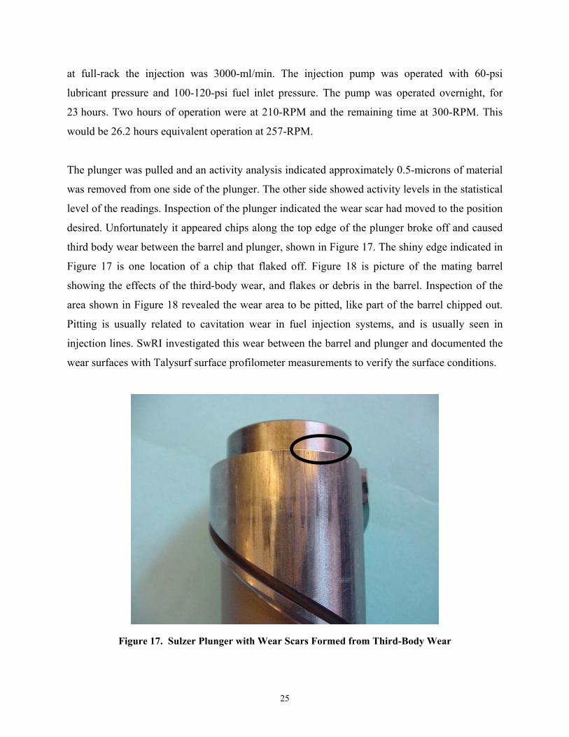
The plunger was pulled and an activity analysis indicated approximately 0.5-microns of material
was removed from one side of the plunger. The other side showed activity levels in the statistical
level of the readings. Inspection of the plunger indicated the wear scar had moved to the position
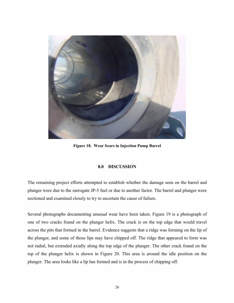
desired. Unfortunately it appeared chips along the top edge of the plunger broke off and caused
third body wear between the barrel and plunger, shown in Figure 17. The shiny edge indicated in
Figure 17 is one location of a chip that flaked off. Figure 18 is picture of the mating barrel
showing the effects of the third-body wear, and flakes or debris in the barrel. Inspection of the
area shown in Figure 18 revealed the wear area to be pitted, like part of the barrel chipped out.
Pitting is usually related to cavitation wear in fuel injection systems, and is usually seen in
injection lines. SwRI investigated this wear between the barrel and plunger and documented the
wear surfaces with Talysurf surface profilometer measurements to verify the surface conditions.
Figure 17. Sulzer Plunger with Wear Scars Formed from Third-Body Wear
26
Figure 18. Wear Scars in Injection Pump Barrel
8.0 DISCUSSION
The remaining project efforts attempted to establish whether the damage seen on the barrel and
plunger were due to the surrogate JP-5 fuel or due to another factor. The barrel and plunger were
sectioned and examined closely to try to ascertain the cause of failure.
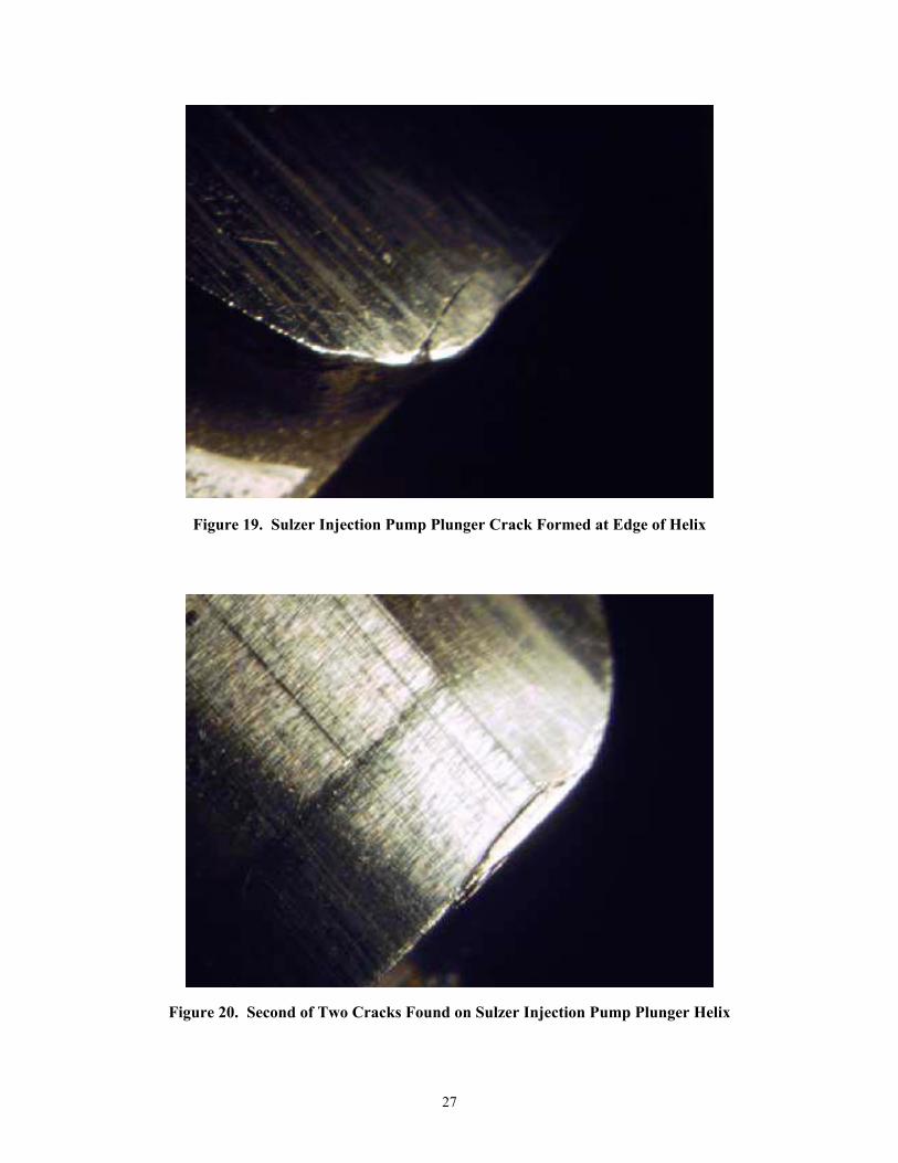
Several photographs documenting unusual wear have been taken. Figure 19 is a photograph of
one of two cracks found on the plunger helix. The crack is on the top edge that would travel
across the pits that formed in the barrel. Evidence suggests that a ridge was forming on the lip of
the plunger, and some of those lips may have chipped off. The ridge that appeared to form was
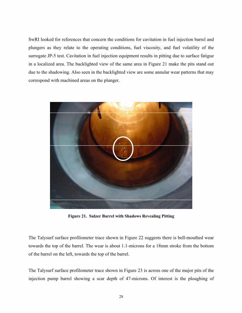
not radial, but extended axially along the top edge of the plunger. The other crack found on the
top of the plunger helix is shown in Figure 20. This area is around the idle position on the
plunger. The area looks like a lip has formed and is in the process of chipping off.
27
Figure 19. Sulzer Injection Pump Plunger Crack Formed at Edge of Helix
Figure 20. Second of Two Cracks Found on Sulzer Injection Pump Plunger Helix
28
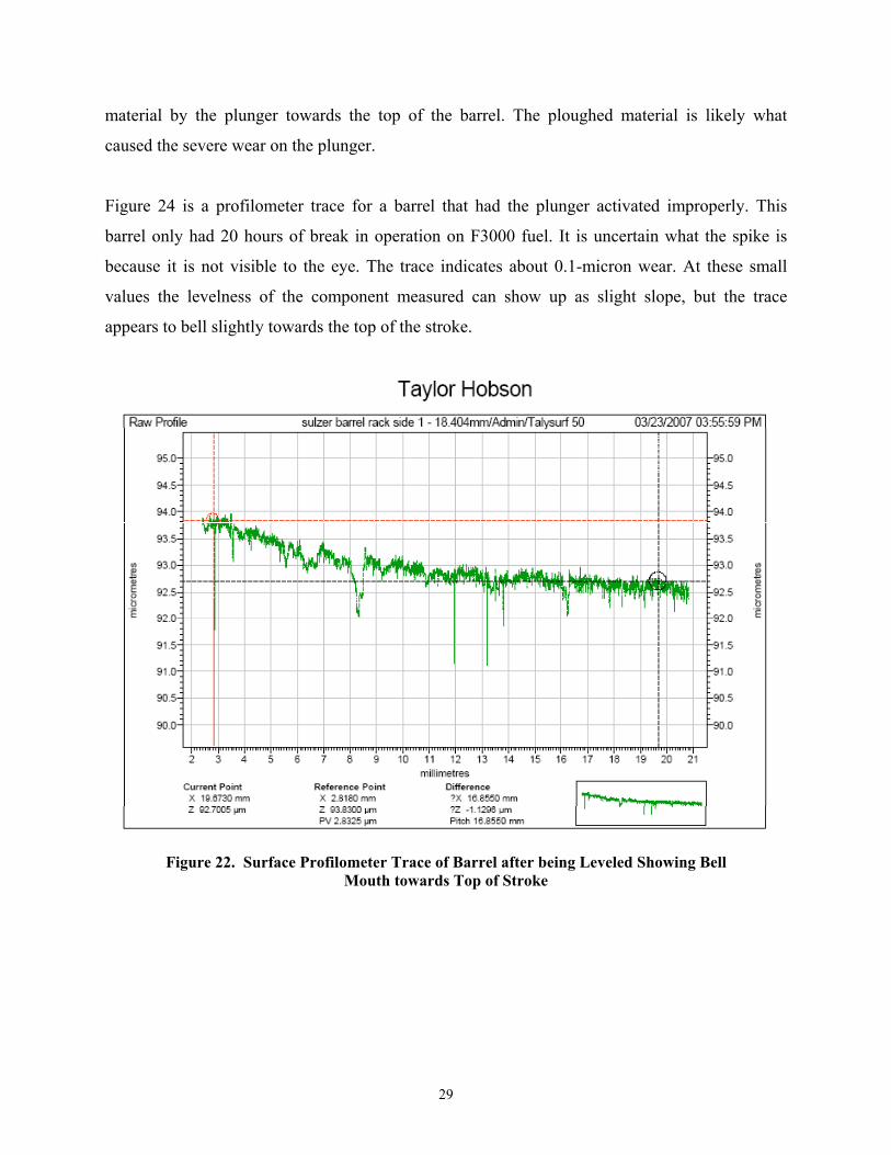
SwRI looked for references that concern the conditions for cavitation in fuel injection barrel and
plungers as they relate to the operating conditions, fuel viscosity, and fuel volatility of the
surrogate JP-5 test. Cavitation in fuel injection equipment results in pitting due to surface fatigue
in a localized area. The backlighted view of the same area in Figure 21 make the pits stand out
due to the shadowing. Also seen in the backlighted view are some annular wear patterns that may
correspond with machined areas on the plunger.
Figure 21. Sulzer Barrel with Shadows Revealing Pitting
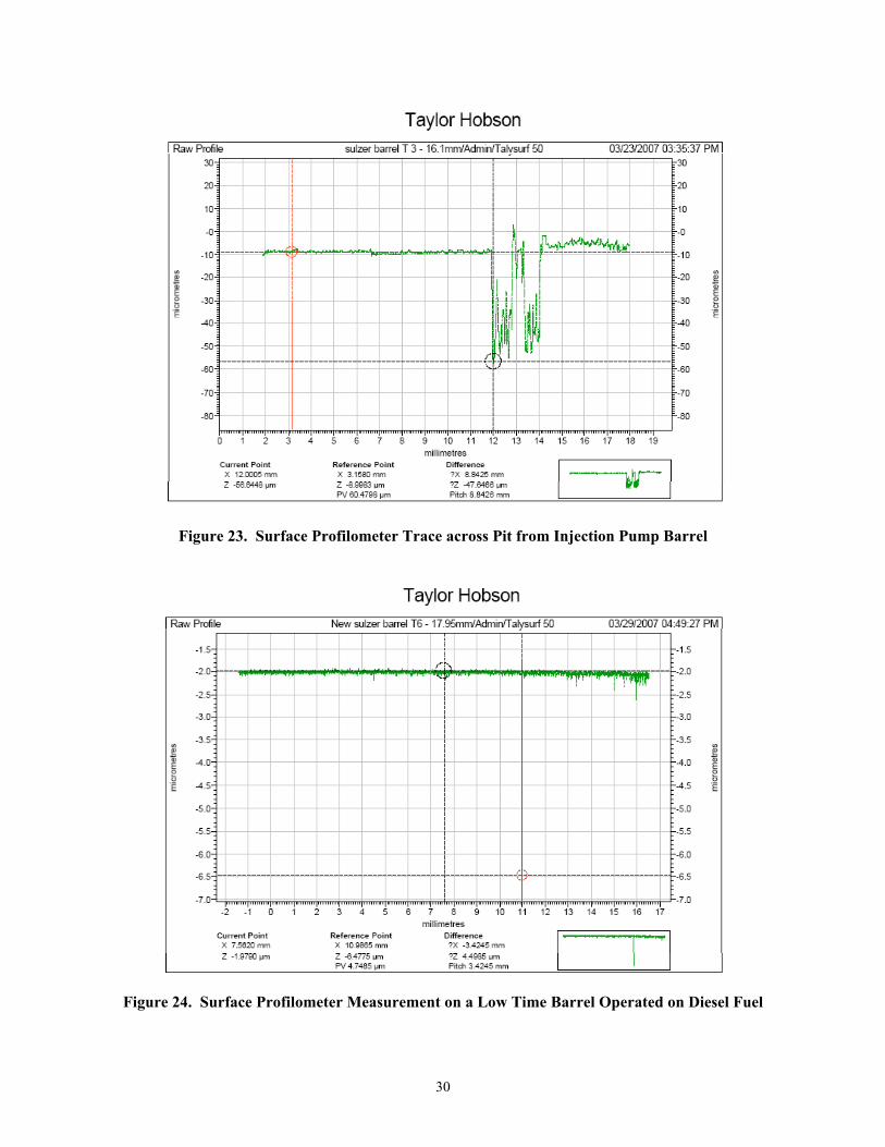
The Talysurf surface profilometer trace shown in Figure 22 suggests there is bell-mouthed wear
towards the top of the barrel. The wear is about 1.1-microns for a 18mm stroke from the bottom
of the barrel on the left, towards the top of the barrel.
The Talysurf surface profilometer trace shown in Figure 23 is across one of the major pits of the
injection pump barrel showing a scar depth of 47-microns. Of interest is the ploughing of
29
material by the plunger towards the top of the barrel. The ploughed material is likely what
caused the severe wear on the plunger.
Figure 24 is a profilometer trace for a barrel that had the plunger activated improperly. This
barrel only had 20 hours of break in operation on F3000 fuel. It is uncertain what the spike is
because it is not visible to the eye. The trace indicates about 0.1-micron wear. At these small
values the levelness of the component measured can show up as slight slope, but the trace
appears to bell slightly towards the top of the stroke.
Figure 22. Surface Profilometer Trace of Barrel after being Leveled Showing Bell Mouth towards Top of Stroke
30
Figure 23. Surface Profilometer Trace across Pit from Injection Pump Barrel
Figure 24. Surface Profilometer Measurement on a Low Time Barrel Operated on Diesel Fuel
31
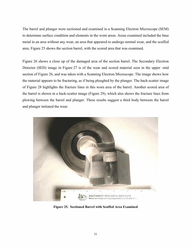
The barrel and plunger were sectioned and examined in a Scanning Electron Microscope (SEM)
to determine surface condition and elements in the worn areas. Areas examined included the base
metal in an area without any wear, an area that appeared to undergo normal wear, and the scuffed
area. Figure 25 shows the section barrel, with the scored area that was examined.
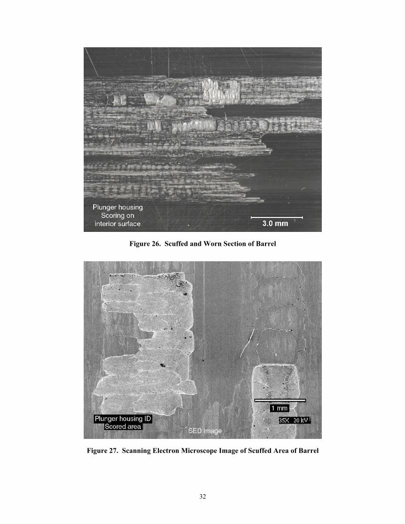
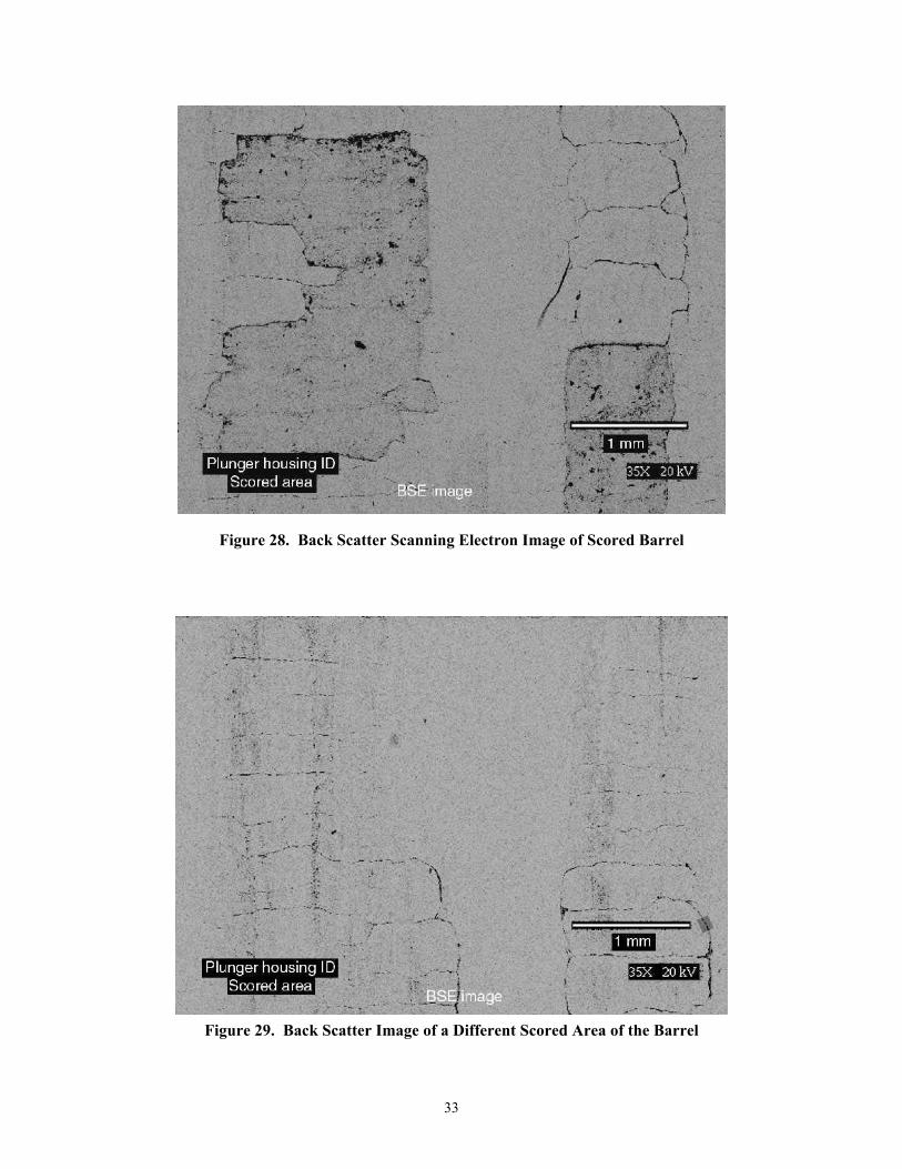
Figure 26 shows a close up of the damaged area of the section barrel. The Secondary Electron
Detector (SED) image in Figure 27 is of the wear and scored material seen in the upper -mid
section of Figure 26, and was taken with a Scanning Electron Microscope. The image shows how
the material appears to be fracturing, as if being ploughed by the plunger. The back-scatter image
of Figure 28 highlights the fracture lines in this worn area of the barrel. Another scored area of
the barrel is shown in a back-scatter image (Figure 29), which also shows the fracture lines from
plowing between the barrel and plunger. These results suggest a third body between the barrel
and plunger initiated the wear.
Figure 25. Sectioned Barrel with Scuffed Area Examined
32
Figure 26. Scuffed and Worn Section of Barrel
Figure 27. Scanning Electron Microscope Image of Scuffed Area of Barrel
33
Figure 28. Back Scatter Scanning Electron Image of Scored Barrel
Figure 29. Back Scatter Image of a Different Scored Area of the Barrel
34
An elemental analysis was performed on an area of the barrel that did not reveal wear and on one
of the scored areas. The un-scored area elemental results matched closely with the base metal
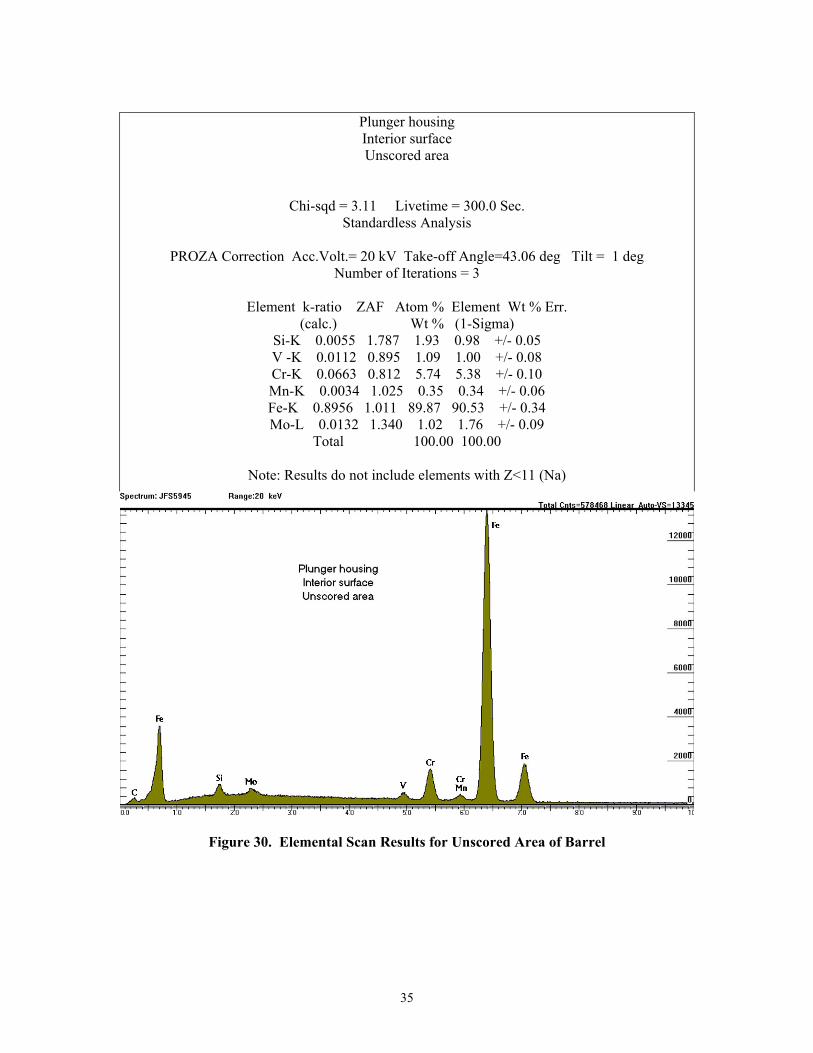
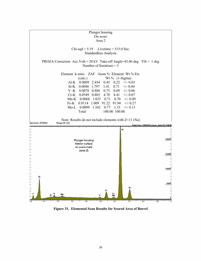
elemental results. Figure 30 details the elemental analysis of the scored area and Figure 31
details the elements found in a scored area of the barrel. An element that shows up in the scored
area is aluminum, which does not show up in the base metal or unscored area elemental scans.
The quantity of aluminum is small, thus alloying elements of are not seen so it is not certain if
the aluminum is from an alloy or from an abrasive such as aluminum oxide.
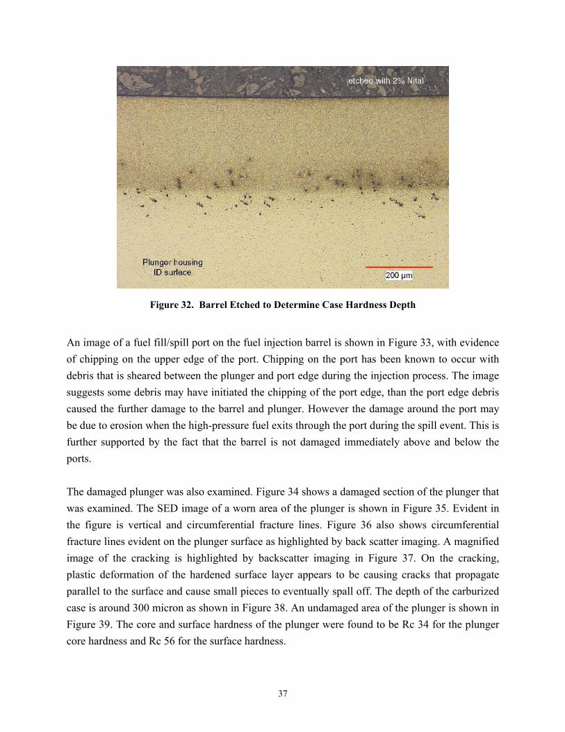
The heat treatment case depth was checked for the barrel. Figure 32 shows the etched barrel
section with the depth of the case hardening around 300-microns.
35
Plunger housing Interior surface Unscored area
Chi-sqd = 3.11 Livetime = 300.0 Sec. Standardless Analysis
PROZA Correction Acc.Volt.= 20 kV Take-off Angle=43.06 deg Tilt = 1 deg
Number of Iterations = 3
Element k-ratio ZAF Atom % Element Wt % Err. (calc.) Wt % (1-Sigma)
Si-K 0.0055 1.787 1.93 0.98 +/- 0.05 V -K 0.0112 0.895 1.09 1.00 +/- 0.08 Cr-K 0.0663 0.812 5.74 5.38 +/- 0.10 Mn-K 0.0034 1.025 0.35 0.34 +/- 0.06 Fe-K 0.8956 1.011 89.87 90.53 +/- 0.34 Mo-L 0.0132 1.340 1.02 1.76 +/- 0.09
Total 100.00 100.00
Note: Results do not include elements with Z<11 (Na)
Figure 30. Elemental Scan Results for Unscored Area of Barrel
36
Plunger housing On score Area 2
Chi-sqd = 5.19 Livetime = 515.0 Sec.
Standardless Analysis
PROZA Correction Acc.Volt.= 20 kV Take-off Angle=43.06 deg Tilt = 1 deg Number of Iterations = 3
Element k-ratio ZAF Atom % Element Wt % Err.
(calc.) Wt % (1-Sigma) Al-K 0.0009 2.454 0.45 0.22 +/- 0.03 Si-K 0.0040 1.797 1.41 0.71 +/- 0.04 V -K 0.0078 0.888 0.75 0.69 +/- 0.06 Cr-K 0.0549 0.803 4.70 4.41 +/- 0.07 Mn-K 0.0068 1.025 0.71 0.70 +/- 0.09 Fe-K 0.9114 1.009 91.22 91.94 +/- 0.27 Mo-L 0.0099 1.342 0.77 1.33 +/- 0.11
Total 100.00 100.00
Note: Results do not include elements with Z<11 (Na)
Figure 31. Elemental Scan Results for Scored Area of Barrel
37
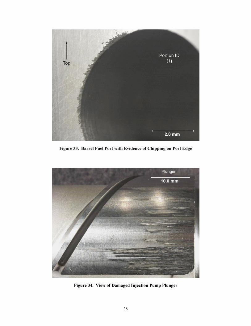
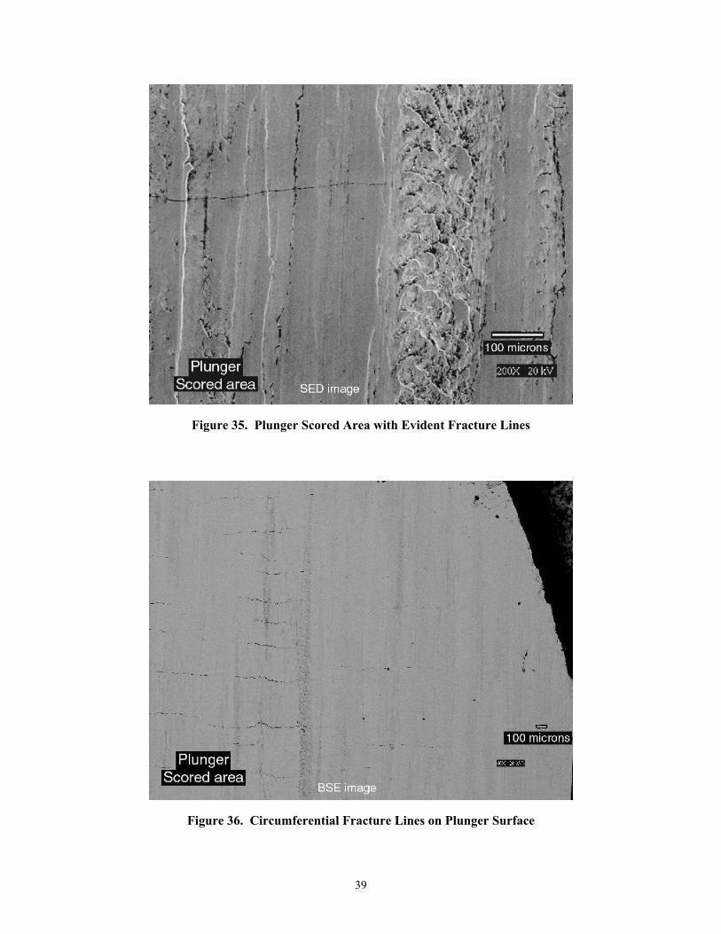
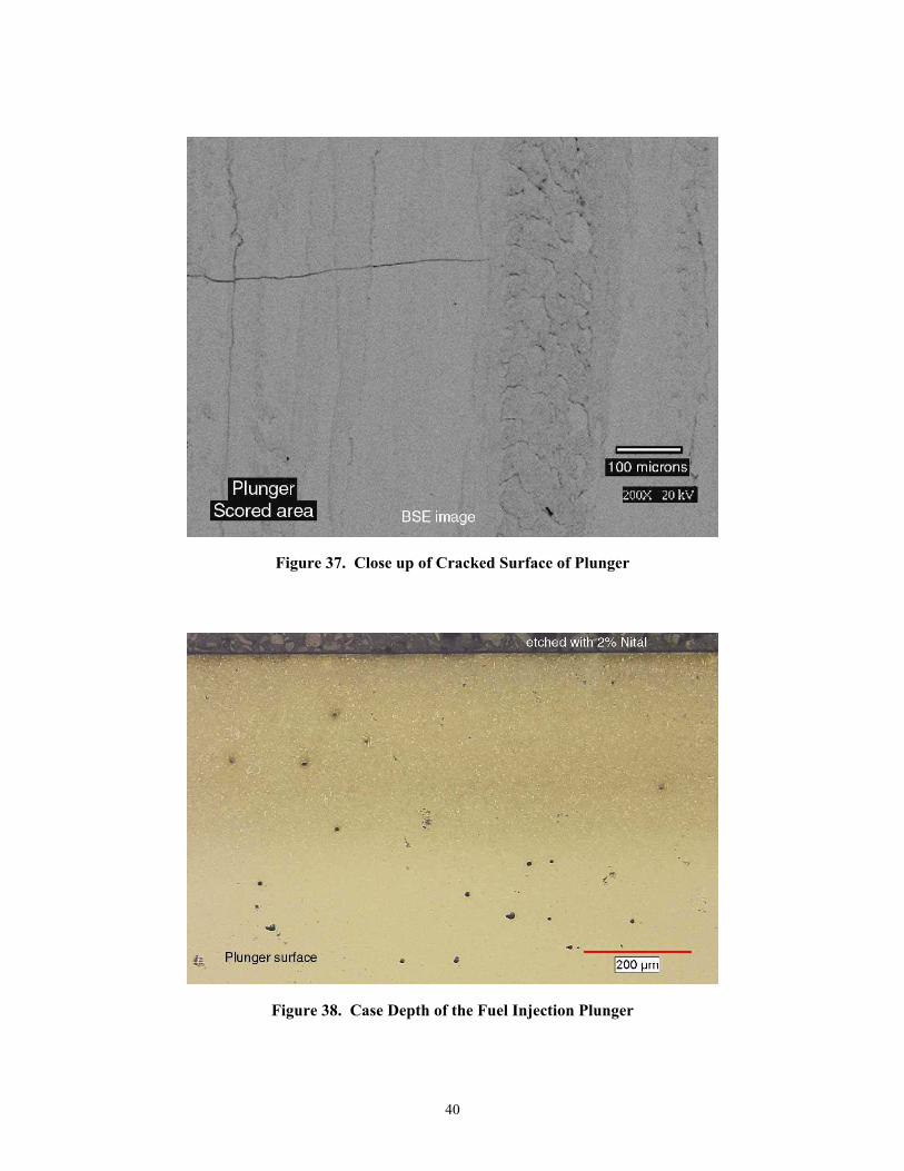
Figure 32. Barrel Etched to Determine Case Hardness Depth An image of a fuel fill/spill port on the fuel injection barrel is shown in Figure 33, with evidence of chipping on the upper edge of the port. Chipping on the port has been known to occur with debris that is sheared between the plunger and port edge during the injection process. The image suggests some debris may have initiated the chipping of the port edge, than the port edge debris caused the further damage to the barrel and plunger. However the damage around the port may be due to erosion when the high-pressure fuel exits through the port during the spill event. This is further supported by the fact that the barrel is not damaged immediately above and below the ports. The damaged plunger was also examined. Figure 34 shows a damaged section of the plunger that was examined. The SED image of a worn area of the plunger is shown in Figure 35. Evident in the figure is vertical and circumferential fracture lines. Figure 36 also shows circumferential fracture lines evident on the plunger surface as highlighted by back scatter imaging. A magnified image of the cracking is highlighted by backscatter imaging in Figure 37. On the cracking, plastic deformation of the hardened surface layer appears to be causing cracks that propagate parallel to the surface and cause small pieces to eventually spall off. The depth of the carburized case is around 300 micron as shown in Figure 38. An undamaged area of the plunger is shown in Figure 39. The core and surface hardness of the plunger were found to be Rc 34 for the plunger core hardness and Rc 56 for the surface hardness.
38
Figure 33. Barrel Fuel Port with Evidence of Chipping on Port Edge
Figure 34. View of Damaged Injection Pump Plunger
39
Figure 35. Plunger Scored Area with Evident Fracture Lines
Figure 36. Circumferential Fracture Lines on Plunger Surface
40
Figure 37. Close up of Cracked Surface of Plunger
Figure 38. Case Depth of the Fuel Injection Plunger
41
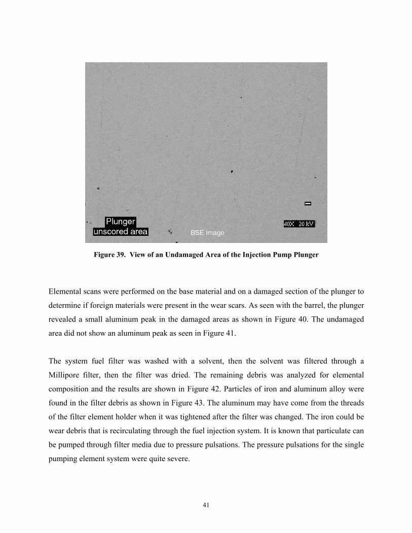
Figure 39. View of an Undamaged Area of the Injection Pump Plunger
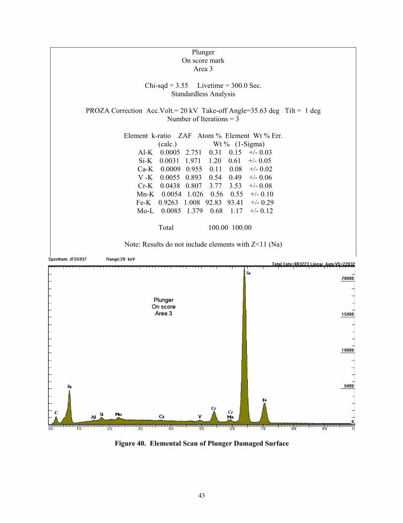
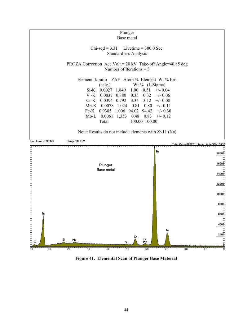
Elemental scans were performed on the base material and on a damaged section of the plunger to
determine if foreign materials were present in the wear scars. As seen with the barrel, the plunger
revealed a small aluminum peak in the damaged areas as shown in Figure 40. The undamaged
area did not show an aluminum peak as seen in Figure 41.
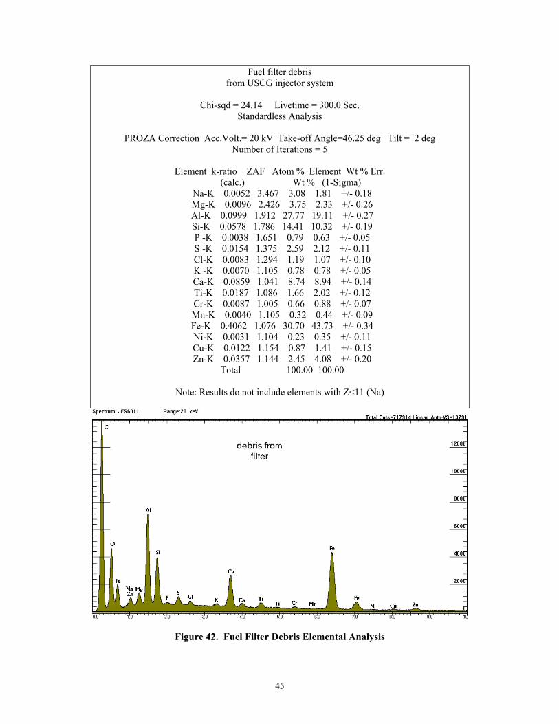
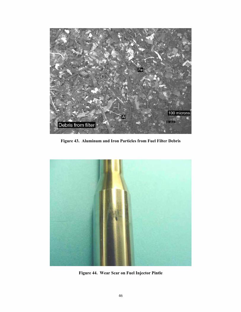
The system fuel filter was washed with a solvent, then the solvent was filtered through a
Millipore filter, then the filter was dried. The remaining debris was analyzed for elemental
composition and the results are shown in Figure 42. Particles of iron and aluminum alloy were
found in the filter debris as shown in Figure 43. The aluminum may have come from the threads
of the filter element holder when it was tightened after the filter was changed. The iron could be
wear debris that is recirculating through the fuel injection system. It is known that particulate can
be pumped through filter media due to pressure pulsations. The pressure pulsations for the single
pumping element system were quite severe.
42
The elemental analysis suggests either aluminum or iron particles were pumped through filter
and resulted in damage to the fuel injection pump. There is very little evidence of scoring
directly around the fill/spill ports that suggests the damage was not due to particle shearing
between the port and the plunger. The damaged areas show evidence of aluminum, as does the
fuel filter debris.
The fuel injector showed evidence of wear also. Figure 44 shows the fuel injector pintle with a
developed wear scar. It is likely the wear scar developed due to material from the barrel and
plunger migrating downstream with the fuel.
43
Plunger On score mark
Area 3
Chi-sqd = 3.55 Livetime = 300.0 Sec. Standardless Analysis
PROZA Correction Acc.Volt.= 20 kV Take-off Angle=35.63 deg Tilt = 1 deg
Number of Iterations = 3
Element k-ratio ZAF Atom % Element Wt % Err. (calc.) Wt % (1-Sigma)
Al-K 0.0005 2.751 0.31 0.15 +/- 0.03 Si-K 0.0031 1.971 1.20 0.61 +/- 0.05 Ca-K 0.0009 0.955 0.11 0.08 +/- 0.02 V -K 0.0055 0.893 0.54 0.49 +/- 0.06 Cr-K 0.0438 0.807 3.77 3.53 +/- 0.08 Mn-K 0.0054 1.026 0.56 0.55 +/- 0.10 Fe-K 0.9263 1.008 92.83 93.41 +/- 0.29 Mo-L 0.0085 1.379 0.68 1.17 +/- 0.12
Total 100.00 100.00
Note: Results do not include elements with Z<11 (Na)
Figure 40. Elemental Scan of Plunger Damaged Surface
44
Plunger Base metal
Chi-sqd = 3.31 Livetime = 300.0 Sec.
Standardless Analysis
PROZA Correction Acc.Volt.= 20 kV Take-off Angle=40.85 deg Number of Iterations = 3
Element k-ratio ZAF Atom % Element Wt % Err.
(calc.) Wt % (1-Sigma) Si-K 0.0027 1.849 1.00 0.51 +/- 0.04 V -K 0.0037 0.880 0.35 0.32 +/- 0.06 Cr-K 0.0394 0.792 3.34 3.12 +/- 0.08 Mn-K 0.0078 1.024 0.81 0.80 +/- 0.11 Fe-K 0.9385 1.006 94.02 94.42 +/- 0.30 Mo-L 0.0061 1.353 0.48 0.83 +/- 0.12
Total 100.00 100.00
Note: Results do not include elements with Z<11 (Na)
Figure 41. Elemental Scan of Plunger Base Material
45
Fuel filter debris from USCG injector system
Chi-sqd = 24.14 Livetime = 300.0 Sec.
Standardless Analysis
PROZA Correction Acc.Volt.= 20 kV Take-off Angle=46.25 deg Tilt = 2 deg Number of Iterations = 5
Element k-ratio ZAF Atom % Element Wt % Err.
(calc.) Wt % (1-Sigma) Na-K 0.0052 3.467 3.08 1.81 +/- 0.18 Mg-K 0.0096 2.426 3.75 2.33 +/- 0.26 Al-K 0.0999 1.912 27.77 19.11 +/- 0.27 Si-K 0.0578 1.786 14.41 10.32 +/- 0.19 P -K 0.0038 1.651 0.79 0.63 +/- 0.05 S -K 0.0154 1.375 2.59 2.12 +/- 0.11 Cl-K 0.0083 1.294 1.19 1.07 +/- 0.10 K -K 0.0070 1.105 0.78 0.78 +/- 0.05 Ca-K 0.0859 1.041 8.74 8.94 +/- 0.14 Ti-K 0.0187 1.086 1.66 2.02 +/- 0.12 Cr-K 0.0087 1.005 0.66 0.88 +/- 0.07 Mn-K 0.0040 1.105 0.32 0.44 +/- 0.09 Fe-K 0.4062 1.076 30.70 43.73 +/- 0.34 Ni-K 0.0031 1.104 0.23 0.35 +/- 0.11 Cu-K 0.0122 1.154 0.87 1.41 +/- 0.15 Zn-K 0.0357 1.144 2.45 4.08 +/- 0.20
Total 100.00 100.00
Note: Results do not include elements with Z<11 (Na)
Figure 42. Fuel Filter Debris Elemental Analysis
46
Figure 43. Aluminum and Iron Particles from Fuel Filter Debris
Figure 44. Wear Scar on Fuel Injector Pintle
47
The analysis suggests it is likely a contaminant entered the fuel injection system and caused the
rapid wear. It is likely the contaminant may have been introduced during the disassembly/
assembly processes that were carried out in order to check plunger activity. Although
considerable care was taken when handling the components, it is possible the plunger could have
been damaged in the disassembly/assembly processes.
However the depth of the wear scars and evidence of pitting suggests there may have been other
mechanisms in effect. The engine and fuel injection equipment manufactures were queried to
determine if cavitation could have been a root cause of the failure; the manufacturers were asked
the following questions:
• An item that is not understood is whether cavitation in the fuel injection pump could have
resulted in surface fatigue that resulted in the damage seen between the barrel and
plunger?
• Could operating the system with a lower viscosity fuel at an elevated operating speed
have induced and accelerated cavitation?
• Can cavitation result in the damage seen in less than 24 hours of operation?
The engine and fuel injection equipment manufacturers declined to respond to the above
questions concerning the experiment and the wear observed in the study.
9.0 CONCLUSIONS
The following conclusions could be made from this work:
• Radioactive Tracer methods can be sensitive, but with heavy metal objects shielding the
radioactive source, in-situ measurements can be imprecise.
48
• The Radioactive Tracer method utilized for the 12ZAV40S plunger was not sensitive
enough to determine wear rates between different lubricity fuels within 72 hours of
operation of a high durability fuel system.
• Within a resolution of 0.14-microns, there was not a difference in wear between a 3000-g
and a 2000-g scuffing load fuel based on radioactive tracer measurements.
• Precise knowledge of wear locations are critical in order to determine fuel wear rates with
Surface Layer Activation methods.
• Rapid wear and damage can occur if contaminants, improper handling, or other factors
such as cavitation are introduced.
• Damage may have been caused by the expanded operating speed of the test fuel injection
system, which was beyond the speed range of the engine in service.
10.0 SUMMARY AND RECOMMENDATIONS
The use of aviation turbine fuel, with corresponding lower viscosity and fuel lubricity, in large
bore diesel engines has been investigated over the years (11, 12). Typically the large bore
engines burning the aviation turbine fuel were at remote locations that supported aviation
activities, or were in colder climates where lower viscosity fuel was required. Generally the
aviation turbine fuel use was acceptable in performance and in a location using Jet-A, acceptable
with a reduction in component durability (13).
Recent studies of aviation turbine fuel grade JP-5 use in Naval shipboard engines have also
indicated the use to be satisfactory (14, 15). However the JP-5 use in the recent surveys has only
been in large engines that serve as Ship Service Diesel Generators and Emergency Diesel
Generators. There is not a large body of information on Main Propulsion use medium-speed
diesel engines burning JP-5. The recent surveys do suggest that since the engines are qualified
49
MILSPEC engines, they would have been required to function on JP-5 as and alternative or
emergency fuel.
The four Sulzer 12ZAV40S engines of the USCG Healy serve as main propulsion and ship
service power. The icebreaking, rescue, research, and polar duty of the USCG Healy suggest an
understanding of the JP-5 effects on the fuel injection system components is critical. As such the
results generated in this study are inconclusive. Operation with the radioactive tracer did suggest
that the wear rates were below the sensitivity of the method. Essentially the fuel injection pump
had operated approximately 150 hours on two different fuels and did not show any reduction in
radioactivity of the test component after correcting for the isotope half-life. The sensitivity of the
SLA method was 0.14-microns of wear in the activated area. The activation profile was based on
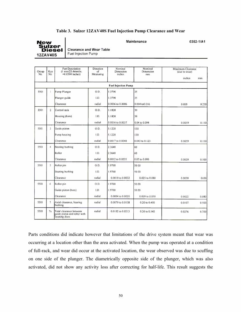
data shown in Table 3 from a technical manual. The allowable wear clearance of the plunger
over the 24000-hour expected fuel injection pump life indicated in the technical manual,
suggested the depth profile target for obtaining wear measurements in approximately 40 hours of
operation.
50
Table 3. Sulzer 12ZAV40S Fuel Injection Pump Clearance and Wear
Parts conditions did indicate however that limitations of the drive system meant that wear was
occurring at a location other than the area activated. When the pump was operated at a condition
of full-rack, and wear did occur at the activated location, the wear observed was due to scuffing
on one side of the plunger. The diametrically opposite side of the plunger, which was also
activated, did not show any activity loss after correcting for half-life. This result suggests the
51
scuffing wear of the plunger was due to an effect other than the lubricity of the test fuel. These
confounding effects could be cavitation or contamination.
Due to the issues involved with in-situ measurements, testing with off-line measurements were
performed that required disassembly of the fuel injection pump to remove the barrel and plunger.
In service the fuel injection pump would certainly never be disassembled. During the evaluations
the fuel injection pump was disassembled several times, with each time there being a risk of
contamination being introduced into the fuel injection pump. Another possible risk was nicking
the plunger during handling or assembly that could introduce a burr into the fuel injection pump.
When operating on JP-5 fuel, the fuel injection pump drain was discharging 10.2 liters of fuel
every four hours. To keep the recirculating fuel system sump at an appropriate level, makeup
fuel was put in every four hours operation. Each batch of makeup fuel could have been a risk
factor for the introduction of contaminants. Although there was a fuel filter in the system, it has
been documented that particles can be pumped through a fuel filter due to hydraulic action and
flexing of the membrane due to pressure fluctuations. For the 12ZAV40S test stand the pressure
fluctuations were quite severe. A long-term test with a single pass fuel system, where the
components are documented at the beginning and end would eliminate the risk of contamination
due to handling and fuel additions.
Cavitation erosion is a failure mechanism in diesel fuel injection systems. Studies have shown
that cavitation in fuel injection pumps can reduce durability and in a pump-line system can show
up around the ports of the barrel and plunger assembly (16). Cavitation is due to the collapse of
fuel vapor bubbles that can lead to high-pressure spikes that may result in surface fatigue or
pitting. Some modeling efforts suggest the venting from the high-pressure chamber above the
plunger, either across the seal path, or when metering port cut-off or spill port opening occurs,
can cause bubble clouds to form (17). The collapse of these bubble clouds can generate localized
high pressures in a fuel injection pump.
Other cavitation modeling efforts suggest that fuel viscosity is one of the most significant
contributors to the potential incidence of cavitation (18). That is because the fuel viscosity is a
dissipating property, thus higher viscosity fuels have a stronger dissipating effect on the
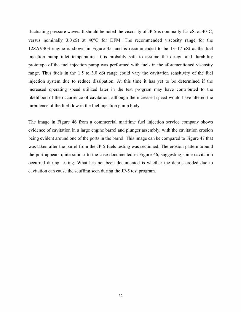
52
fluctuating pressure waves. It should be noted the viscosity of JP-5 is nominally 1.5 cSt at 40°C,
versus nominally 3.0 cSt at 40°C for DFM. The recommended viscosity range for the
12ZAV40S engine is shown in Figure 45, and is recommended to be 13–17 cSt at the fuel
injection pump inlet temperature. It is probably safe to assume the design and durability
prototype of the fuel injection pump was performed with fuels in the aforementioned viscosity
range. Thus fuels in the 1.5 to 3.0 cSt range could vary the cavitation sensitivity of the fuel
injection system due to reduce dissipation. At this time it has yet to be determined if the
increased operating speed utilized later in the test program may have contributed to the
likelihood of the occurrence of cavitation, although the increased speed would have altered the
turbulence of the fuel flow in the fuel injection pump body.
The image in Figure 46 from a commercial maritime fuel injection service company shows
evidence of cavitation in a large engine barrel and plunger assembly, with the cavitation erosion
being evident around one of the ports in the barrel. This image can be compared to Figure 47 that
was taken after the barrel from the JP-5 fuels testing was sectioned. The erosion pattern around
the port appears quite similar to the case documented in Figure 46, suggesting some cavitation
occurred during testing. What has not been documented is whether the debris eroded due to
cavitation can cause the scuffing seen during the JP-5 test program.
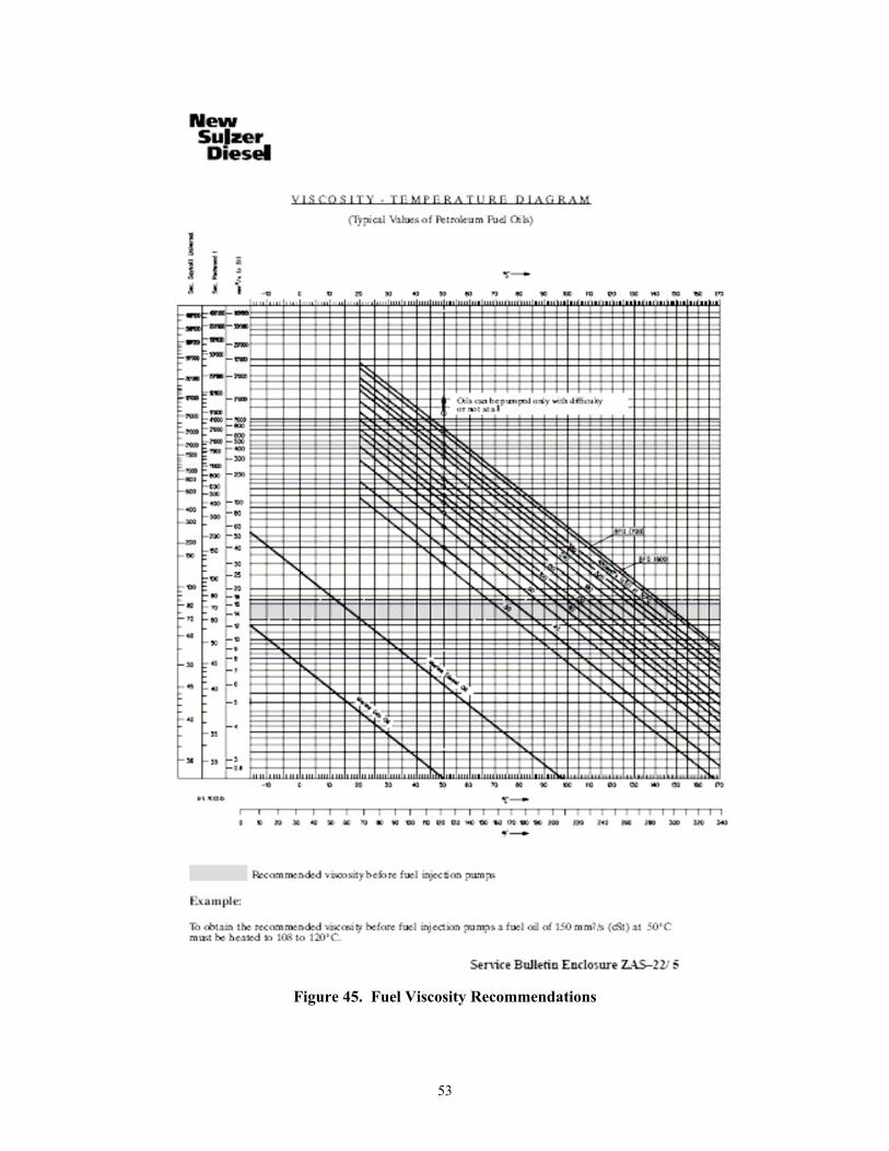
53
Figure 45. Fuel Viscosity Recommendations
54
Figure 46. Documented Cavitation from Commercial Diesel Service Company
Figure 47. Barrel Port from JP-5 Test Program with Evidence of Cavitation-like Erosion
55
Due to complications, the radioactive tracer approach was not suitable to determine wear in the
12ZAV40S fuel injection system. Some type of controlled durability test would be required to
determine suitability of JP-5. Indicators suggest short term JP-5 usage would likely be suitable,
however evidence of cavitation erosion suggest long term use may be questionable. However the
cavitation erosion seen was not documented for both fuels examined, nor is it certain whether the
expanded speed operating conditions may have contributed to accelerating the cavitation erosion.
Two approaches are suggested for determining wear with JP-5 without risk to the Healy and
without experimental method altering the result:
• A controlled test of an operating engine where one cylinder is isolated to operate on JP-5
for a significant number of hours. Component condition would be compared to one of the
other cylinder conditions. The components would be new at the start of testing and at the
end of testing evaluated for condition. The components evaluated should be a barrel and
plunger and a fuel injector. Fuel injectors are apparently more highly susceptible to
cavitation erosion that the fuel injection pumps. A similar approach is detailed in SAE
paper 2002-01-1700 that looked at a Wartsila VASA 9R32 diesel engine with varying
lubricity fuels (19). The difficulty in this approach would be identifying a suitable engine
for use or whether an engine on the Healy can be used to screen the fuels.
• A single pass pump rig test of a significant quantity of an aviation turbine type fuel, such
that the effects of additive changes, fuels additions, component disassemblies and fuel/oil
migration are not compounded. The wear on the barrel and plunger of the test fuel could
be compared to an installed barrel and plunger and injector that has been removed from
the Healy that was burning DFM. SwRI has an aviation fuel filtration facility for
challenging large fuel distribution filters with 12,000-gallons of fuel in a single pass test
mode. At 3L/min injection rate the rig could run for 250 hours without having to handle
the fuel. The fuel could be clay treated, re-additized, and used again for a second pass to
obtain 500-hour challenge to the fuel injection equipment. The fuel injection pump rig
would be operated at the recommended engine speed, full-rack, and fuel inlet and outlet
conditions and the lubricating oil inlet condition.
56
11.0 REFERENCES
1. New Sulzer Diesel, Service Bulletin ZAS-22, Adjustments of Fuel Oil Systems, Technical
Information to all the Owners of Sulzer ZA 40S Type Diesel Engines, 8-11-96.
2. S9233-DH-MMC.010, 0910-LP-016-7490, Volume 1, Technical Manual for Engine, Main
Diesel, Type 12ZAV40S, Technical Manual Supplement, USCGC Healy (WAGB 20).
3. S9233-DH-MMC-020, 0910-LP-016-7500, Volume 2, Technical Manual for Engine, Main
Diesel, Type 12AV40S, Operating Manual, USCGC Healy (WAGB 20).
4. S9233-DH-MMC-030, 0910-LP-016-7510, Volume 3, Technical Manual for Engine, Main
Diesel, Type 12AV40S, Maintenance Manual, USCGC Healy (WAGB 20).
5. S9233-DH-MMC-040, 0910-LP-016-7520, Volume 4, Technical Manual for Engine, Main
Diesel, Type 12ZAV40S, Spare Parts Code Book, USCGC Healy (WAGB 20).
6. S9233-DH-MMC-050, 0910-LP-016-7530, Volume 5, Part 1, Technical Manual for
Engine, Main Diesel, Type 12ZAV40S, Auxiliary Equipment Manual, USCGC Healy
(WAGB 20).
7. S9233-DH-MMC-060, 0910-LP-016-7540, Volume 5, Part 2, Technical Manual for
Engine, Main Diesel, Type 12AV40S, Auxiliary Equipment Manual, USCGC Healy
(WAGB 20).
8. Correspondence on Coupon Activation and Wear Profiles, Charles C. Blatchley, Ph.D.,
Chair, Dept. of Physics, Pittsburg State University, Pittsburg, Kansas, August 19, 2004.
9. Correspondence on Accidental Activation of Plunger Edge, Kenneth Oxorn, Ph.D., Senior
Physicist, ANS Technologies, Montreal, Quebec, Canada, December 10, 2004.
57
10. P.I. Lacey, "Evaluation of Thermally Induced Injection Pump Seizures and the Effects of
Lubricating Oil Additions on Aviation Turbine Fuel Lubricity," BFLRF Letter Report 97-
001, Belvoir Fuels and Lubricants Research Facility(SwRI), Southwest Research Institute,
December 1991.
11. Technical Note N-743, "The Use of JP-5 Aviation Turbine Fuel in Large Bore, Low Speed
Diesel Engines," William W. Watson, U.S. Naval Civil Engineering Laboratory, Port
Hueneme, California, 15 November 1965.
12. "Limited Survey of Large Bore Prime Power and Auxiliary Diesel Engines and Fuel Used
in Remote DOD Locations," U.S. Army Belvoir Research, Development, and Engineering
Center, Fort Belvoir, VA, Belvoir Fuels and Lubricants Research Facility (SwRI), San
Antonio, TX, 17 April 1992.
13. Correspondence on Jet-A Fuel Use in Cooper Bessemer Prime Power Engines, Richard O.
Dorsey, Power Plant Foreman, Naval Computer and Telecommunications Station Cutler,
Maine, April 20, 1992.
14. John J. McMullen Associates, Inc., Subj: Contract N00024-99-C-4055, Delivery Order
0078, “Diesel Engine Engineering Support,” JP-5 Navy Single Fuel at Sea Study of
Impacts on Diesel Engines, Task 2.2, Quantify the Major Portion of Fleet Diesel Engine
Maintenance Costs and Project Cost Savings if JP-5 is Used as the Single Shipboard Fuel,
Final Report (A003), March 29, 2004.
15. John J. McMullen Associates, Inc., Subj: Contract N00024-99-C-4055, DELIVERY
ORDER 0078, “Diesel Engine Engineering Support,” JP-5 Navy Single Fuel at Sea Study
of Impacts on Diesel Engines, TASK 2.1, Engine Matrix, Final Report (A002), 29 March
2004.
16. Fuel Injection and Controls for Internal Combustion Engines, P.G.Burman and Frank
DeLuca, American Bosch Arma Corporation, 1962, Library of Congress 62-12020.
58
17. SAE 981023, " Numerical Study of the Cloud Cavitation in a Fuel Injection Pump,"
Shimada et al., ZEXEL Corp., International Congress and Exposition, Detroit, Michigan,
February 23-26, 1998.
18. SAE 2007-01-0245, "Evaluation of the Predictive Capability of Diesel Nozzle Cavitation
Models," E. Giannadakis, D. Papoulias, M. Gavaises and C. Arcoumanis, The City
University London, C. Soteriou and W. Tang, Delphi Diesel Systems, 2007 World
Congress, Detroit, Michigan, April 16-19, 2007.
19. SAE 2002-01-1700, "Investigation of Diesel Fuel Lubricity and Evaluation of Bench Tests
to Correlate with Medium and Heavy Duty Diesel Fuel Injection Equipment Component
Wear – Part 1," Clint Gray, Aaron Wilcox, Michael Scott and Gary Webster, Advanced
Engine Technology Ltd., International Spring Fuels & Lubricants Meeting & Exhibition,
Reno, Nevada, May 6-9, 2002.