Embed Size (px)
Citation preview
UNCLASSIFIED
UNCLASSIFIED
LUBRICITY DOSER EVALUATION STUDIES ON HIGH PRESSURE COMMON RAIL FUEL SYSTEM
INTERIM REPORT
TFLRF No. 447
by
Nigil Jeyashekar, Ph.D., P.E. Robert Warden Edwin A. Frame
U.S. Army TARDEC Fuels and Lubricants Research Facility Southwest Research Institute
® (SwRI
®)
San Antonio, TX
for
Patsy A. Muzzell U.S. Army TARDEC
Force Projection Technologies Warren, Michigan
Contract No. W56HZV-09-C-0100 (WD17 Task 8)
UNCLASSIFIED: Distribution Statement A. Approved for public release
May 2014
ADA
UNCLASSIFIED
UNCLASSIFIED
Reference herein to any specific commercial company, product, process, or service by trade name, trademark, manufacturer, or otherwise, does not necessarily constitute or imply its endorsement, recommendation, or favoring by the United States Government or the Department of the Army (DoA). The opinions of the authors expressed herein do not necessarily state or reflect those of the United States Government or the DoA, and shall not be used for advertising or product endorsement purposes.
Contracted Author As the author(s) is(are) not a Government employee(s), this document was only reviewed for export controls, and improper Army association or emblem usage considerations. All other legal considerations are the responsibility of the author and his/her/their employer(s).
DTIC Availability Notice Qualified requestors may obtain copies of this report from the Defense Technical Information Center, Attn: DTIC-OCC, 8725 John J. Kingman Road, Suite 0944, Fort Belvoir, Virginia 22060-6218.
Disposition Instructions Destroy this report when no longer needed. Do not return it to the originator.
UNCLASSIFIED
UNCLASSIFIED
LUBRICITY DOSER EVALUATION STUDIES ON HIGH PRESSURE COMMON RAIL FUEL SYSTEM
INTERIM REPORT TFLRF No. 447
by
Nigil Jeyashekar, Ph.D., P.E. Robert Warden Edwin A. Frame
U.S. Army TARDEC Fuels and Lubricants Research Facility Southwest Research Institute
® (SwRI
®)
San Antonio, TX
For
Patsy A. Muzzell U.S. Army TARDEC
Force Projection Technologies Warren, Michigan
Contract No. W56HZV-09-C-0100 (WD17 Task 8) SwRI® Project No. 08.14734.17.120
UNCLASSIFIED: Distribution Statement A. Approved for public release
May 2014
Approved by:
Gary B. Bessee, Director U.S. Army TARDEC Fuels and Lubricants Research Facility (SwRI®)
UNCLASSIFIED
UNCLASSIFIED
iv
REPORT DOCUMENTATION PAGE Form Approved
OMB No. 0704-0188 Public reporting burden for this collection of information is estimated to average 1 hour per response, including the time for reviewing instructions, searching existing data sources, gathering and maintaining the data needed, and completing and reviewing this collection of information. Send comments regarding this burden estimate or any other aspect of this collection of information, including suggestions for reducing this burden to Department of Defense, Washington Headquarters Services, Directorate for Information Operations and Reports (0704-0188), 1215 Jefferson Davis Highway, Suite 1204, Arlington, VA 22202-4302. Respondents should be aware that notwithstanding any other provision of law, no person shall be subject to any penalty for failing to comply with a collection of information if it does not display a currently valid OMB control number. PLEASE DO NOT RETURN YOUR FORM TO THE ABOVE ADDRESS.
1. REPORT DATE (DD-MM-YYYY)
5-27-2014 2. REPORT TYPE
Interim Report 3. DATES COVERED (From - To)
June 2011 – May 2014
4. TITLE AND SUBTITLE
Lubricity Doser Evaluation Studies on High Pressure Common Rail Fuel Systems
5a. CONTRACT NUMBER
W56HZV-09-C-0100
5b. GRANT NUMBER
5c. PROGRAM ELEMENT NUMBER
6. AUTHOR(S)
Warden, Robert; Frame, Edwin; Jeyashekar, Nigil 5d. PROJECT NUMBER
SwRI 08.14734.17.120, and
08.14734.17.901
5e. TASK NUMBER
WD 17
5f. WORK UNIT NUMBER
7. PERFORMING ORGANIZATION NAME(S) AND ADDRESS(ES) 8. PERFORMING ORGANIZATION REPORT NUMBER
U.S. Army TARDEC Fuels and Lubricants Research Facility (SwRI®)
Southwest Research Institute®
P.O. Drawer 28510
San Antonio, TX 78228-0510
TFLRF No. 447
9. SPONSORING / MONITORING AGENCY NAME(S) AND ADDRESS(ES) 10. SPONSOR/MONITOR’S ACRONYM(S)
U.S. Army RDECOM
U.S. Army TARDEC 11. SPONSOR/MONITOR’S REPORT
Force Projection Technologies NUMBER(S)
Warren, MI 48397-5000
12. DISTRIBUTION / AVAILABILITY STATEMENT
UNCLASSIFIED: Dist A
Approved for public release; distribution unlimited 13. SUPPLEMENTARY NOTES
14. ABSTRACT
A series of tests were conducted to evaluate the impact of a slow-release lubricity dosing filter for equipment protection and storage
stability. The hardware system used for testing was a high-pressure common rail system found on John Deere 4.5L Powertech Engines. The
completion of a modified test protocol based on the NATO test cycle was set as the passing criterion at 60 oC, 82.8
oC, and 93.3
oC. These
results were compared to the results from WD 04 (Task XIX) at similar temperatures, where in the fuels were treated in bulk with DCI-4A.
Based on this criterion, the dosing filter was effective in improving the performance of Jet A at 82.8 oC, and 93.3
oC. It was ineffective in
improving the performance for SPK at any temperature. The performance of the dosing filter was comparable to direct DCI-4A treatment
for 50/50 Jet A/SPK fuel blend. HRD fuel passed the test cycle without the lubricity additive doser at all test temperatures.
15. SUBJECT TERMS
Jet A, Synthetic Paraffinic Kerosene (SPK), High Pressure Common Rail (HPCR), Dosing Filter
16. SECURITY CLASSIFICATION OF: 17. LIMITATION OF ABSTRACT
18. NUMBER OF PAGES
19a. NAME OF RESPONSIBLE PERSON Nigil Jeyashekar
a. REPORT
Unclassified
b. ABSTRACT
Unclassified
c. THIS PAGE
Unclassified
Unclassified
19
19b. TELEPHONE NUMBER (include area code)
210-522-2533
Standard Form 298 (Rev. 8-98) Prescribed by ANSI Std. Z39.18
UNCLASSIFIED
UNCLASSIFIED
v
EXECUTIVE SUMMARY
Military ground vehicles use fuel-lubricated injection pumps to obtain acceptable performance
and the bulk fuel is treated with additives, such as DCI-4A, to improve lubricity. The objective
of this project was to evaluate the effectiveness of a lubricity additive dosing filter and compare
it to the effectiveness of bulk treatment of the fuel. A modified test protocol based on the NATO
400-hour test cycle was adopted for this project. The completion of this test cycle using a HPCR
fuel pump was set as the passing criterion at 60 ºC, 82.8 ºC, and 93.3 ºC. These results were
compared to the results of the test cycle, at similar temperatures, where the fuels were treated in
bulk with DCI-4A. When the additive is applied at point-of-use, rather than to bulk fuel
quantities, there could potentially be financial savings associated with lower additive costs.
The dosing filter for the program was manufactured by Fleetguard and contains a slow-release
lubricity additive. Equipment compatibility was conducted using a High Pressure Common Rail
(HPCR) fuel system found on a John Deere 4.5L PowetechPlus engine. The three fuels that were
tested on the HPCR test rig with the dosing filter and the respective test temperatures are: Jet A,
Fischer-Tropsch Synthetic Paraffinic Kerosene (SPK), and 50/50 Jet A/SPK blend. In addition to
the above fuels, Jet A and Hydro-treated Renewable Diesel with no lubricity doser were tested.
The three temperatures used for testing were 60 ºC, 82.8 ºC, and 93.3 ºC. These temperatures
were based upon previous work conducted with this fuel system, under WD 4 (Task 19), to help
comparison between previous and current tests. There was no apparent difference in component
wear observed for the 82.8 ºC test, for the blend treated at max DCI-4A versus the blend with the
use of dosing filter. It is concluded that the effect of lubricity additive dosing filter is comparable
to DCI-4A treat rates and that neither method can improve the performance of the fuel blend at
93.3 °C.
The dosing filter was effective in improving the performance of Jet A in a HPCR system by
enabling completion of the entire 400 hour test at 82.8 ºC and 93.3 ºC.
Jet A fuel without the dosing filter and no lubricity additive treatment was able to complete the
400 hour test only at 60 ºC. Jet A treated with 9ppm of DCI-4A was able to complete the 400
hour test for all three test temperatures. The fuel passed all three test temperatures, when a
UNCLASSIFIED
UNCLASSIFIED
vi
lubricity dosing filter was used, implying that the lubricity doser had the same level of
performance of DCI-4A at a minimum treat rate (9 ppm). In terms of component compatibility,
when the test results were considered along with the previous data for system tests that used fuel
additized at 9 ppm with DCI-4A, it was concluded that the additive and dosing filter both have a
comparable and positive impact on system durability with the fuel. SPK fuel treated with 9 ppm
of DCI-4A and no lubricity additive dosing filter, completed the 400 hour test cycle at 60 ºC,
while it failed at 93.3 ºC with a run time of 4 hours. Clay treated SPK fuel, with the use of a
lubricity additive dosing filter, failed the test cycle at 60 ºC. It was concluded that the lubricity
additive dosing filter was ineffective in improving the performance of SPK fuel and that the fuel
would fail further test cycles at elevated temperatures.
In the absence of a lubricity dosing filter, the fuel blend containing 50/50 Jet A/SPK blend
passed the test cycle with a minimum treat rate (9 ppm) at 60 ºC and a maximum treat rate
(22.5 ppm) at 82.8 ºC, while the fuel blend failed the test at 93.3 ºC at both minimum and
maximum treat rates. When a lubricity dosing filter was implemented, the fuel blend passed the
test cycle at 60 ºC and 82.8 ºC, while it failed at 93.3 ºC. Therefore, it was concluded that the
effect of lubricity additive dosing filter was comparable to DCI-4A treat rates and that neither
method could have improved the performance of the fuel blend at 93.3 ºC. It was also concluded
that the performance of the SPK blend with dosing filter was improved by blending Jet A with
SPK at 60 ºC and 82.8 ºC. However, blending Jet A with SPK was not sufficient to pass the
cycle test run at 93.3 ºC. The test cycle at 93.3 ºC resulted in failure of the pump, with the
remaining lower temperatures being able to complete the full 400 hour cycle. While the test at
82.8 ºC completed the 400 hour test, based on component evaluations, there were signs that
continued use of the fuel may have resulted in pump failure. HRD fuel passed the test cycle at
82.8 ºC and 93.3 ºC, without the dosing filter leading to the conclusion that the performance of
HRD fuel without the dosing filter was comparable to the performance of Jet A fuel with the
dosing filter and was most definitely superior compared to the performance of Jet A without the
dosing filter and 50/50 Jet A/SPK blend with the dosing filter. The higher viscosity of the HRD
fuel may be a factor affecting HPCR pump wear performance compared to Jet A and SPK blend
fuels.
UNCLASSIFIED
UNCLASSIFIED
vii
FOREWORD/ACKNOWLEDGMENTS
The U.S. Army TARDEC Fuel and Lubricants Research Facility (TFLRF) located at Southwest
Research Institute (SwRI), San Antonio, Texas, performed this work during the period June 2011
through May 2014 under Contract No. W56HZV-09-C-0100. The U.S. Army Tank Automotive
RD&E Center, Force Projection Technologies, Warren, Michigan administered the project. Mr.
Eric Sattler (RDTA-SIE-ES-FPT) served as the TARDEC contracting officer’s technical
representative. Ms. Patsy A. Muzzell of TARDEC served as project technical monitor.
The authors would like to acknowledge the contribution of the TFLRF technical and
administrative support staff.
UNCLASSIFIED
viii
TABLE OF CONTENTS
Section Page
EXECUTIVE SUMMARY ........................................................................................................................... V FOREWORD/ACKNOWLEDGMENTS ................................................................................................... VII LIST OF TABLES ............................................................................................................................ ix LIST OF FIGURES ....................................................................................................................................... X ACRONYMS AND ABBREVIATIONS .................................................................................................... XI 1.0 INTRODUCTION AND OBJECTIVE ............................................................................................... 1 2.0 LUBRICITY ADDITIVE DOSING FILTER ..................................................................................... 1 3.0 LONG TERM FUEL STORAGE STABILITY STUDY .................................................................... 4 4.0 TEST CYCLE PERFORMANCE EVALUATION ............................................................................ 6
4.1 TEST EQUIPMENT AND TEST CYCLE ........................................................................................... 6 4.2 TEST FUELS AND NATO TEST CYCLE RESULTS ......................................................................... 10 4.3 COMPARISON WITH TEST CYCLE RESULTS FROM WD 04 (TASK XIX) ....................................... 12
5.0 FUEL – COMPONENT COMPATIBILITY EVALUATION .......................................................... 13
5.1 IMPACT OF JET A ON COMPONENT COMPATIBILITY.................................................................. 13 5.2 IMPACT OF SPK ON COMPONENT COMPATIBILITY .................................................................... 15 5.3 IMPACT OF JET A/SPK FUEL BLEND ON COMPONENT COMPATIBILITY ...................................... 17 5.4 IMPACT OF HRD ON COMPONENT COMPATIBILITY ................................................................... 19
6.0 CONCLUSIONS ............................................................................................................................... 21 7.0 REFERENCES .................................................................................................................................. 22 APPENDIX A. FUEL LUBRICITY MEASUREMENTS .................................................................. A-1
UNCLASSIFIED
ix
LIST OF TABLES
Table Page
Table 1. Storage Stability Test Data – Density and Percent Additive Remaining ........................................ 5 Table 2. Test Cycle for John Deere HPCR Pump Stand ............................................................................. 10 Table 3. Test Fuels and Summary of Results .............................................................................................. 11 Table 4. Test Cycle Results for Equipment Compatibility Studies in WD 04 (Task XIX) [7]
* ................. 12
Table A-1. Jet A Fuel without Lubricity Doser ........................................................................................ A-2 Table A-2. Jet A Fuel with Lubricity Doser ............................................................................................. A-2 Table A-3. SPK Fuel with Lubricity Doser .............................................................................................. A-2 Table A-4. 50/50 Jet A/SPK Fuel Blend with Lubricity Doser ................................................................ A-2 Table A-5. HRD Fuel without Lubricity Doser ....................................................................................... A-2
UNCLASSIFIED
x
LIST OF FIGURES
Figure Page
Figure 1. Lubricity Dosing Cup .................................................................................................................... 1 Figure 2. BOCLE Response to Additive Concentration ............................................................................... 3 Figure 3. HFRR Response to Additive Concentration .................................................................................. 4 Figure 4. Storage Stability Test – End-Of-Test Fluid, Jet A in Filter No. 4 ................................................. 5 Figure 5. High Pressure Common Rail Test Rig .......................................................................................... 7 Figure 6. Rotation of Eccentric Lobe and Ring Cam within High Pressure Pump ....................................... 8 Figure 7. Dosing Filter on HPCR Test Rig ................................................................................................... 9 Figure 8. Pump Stand Schematic with Dosing Filter and Clay Treat Tower ................................................ 9 Figure 9. Jet A Component Compatibility – Upper Ring Cam Face .......................................................... 14 Figure 10. Jet A Component Compatibility – Lower Ring Cam Face ........................................................ 14 Figure 11. Jet A Component Compatibility – Upper Plunger Face ............................................................ 14 Figure 12. Jet A Component Compatibility – Lower Plunger Face ............................................................ 14 Figure 13. Plunger and Ring Cam Face – SPK Fuel with Lubricity Doser at 60 °C .................................. 16 Figure 14. Component Evaluation – SPK Fuel with Lubricity Doser at 60 °C .......................................... 16 Figure 15. 50/50 Jet A/SPK Blend Component Compatibility – Upper Ring Cam Face ........................... 17 Figure 16. 50/50 Jet A/SPK Blend Component Compatibility – Lower Ring Cam Face ........................... 17 Figure 17. 50/50 Jet A/SPK Blend Component Compatibility – Upper Plunger Face ............................... 18 Figure 18. 50/50 Jet A/SPK Blend Component Compatibility – Lower Plunger Face ............................... 18 Figure 19. 50/50 Jet A/SPK Blend Component Compatibility –Ring Cam Bushing ................................. 19 Figure 20. 50/50 Jet A/SPK Blend Component Compatibility –Cam Lobe ............................................... 19 Figure 21. HRD – Component Compatibility Evaluation at 82.8 ºC, No Lubricity Doser ......................... 20 Figure 22. HRD – Component Compatibility Evaluation at 93.3 ºC, No Lubricity Doser ......................... 20 Figure 23. Cam Lobe Comparison between 82.8 ºC and 93.3 ºC – HRD, No Lubricity Doser .................. 20
UNCLASSIFIED
xi
ACRONYMS AND ABBREVIATIONS
% Percent
ASTM American Society for Testing and Materials
BOCLE Ball-On-Cylinder Lubricity Evaluator
cSt CentiStoke
CI/LI Corrosion Inhibitor/Lubricity Improver
˚C Degrees Centigrade
˚F Degrees Fahrenheit
HFRR High Frequency Reciprocating Rig
HPCR High Pressure Common Rail
JD John Deere
kW Kilowatt
mm Millimeter
NATO North Atlantic Treaty Organization
ppm Parts per million
psi Pounds per square inch
RPM Revolutions per minute
SwRI Southwest Research Institute
SPK Synthetic paraffinic kerosene
TARDEC Tank Automotive Research, Development and Engineering Center
TFLRF TARDEC Fuels and Lubricants Research Facility
WSD Wear Scar Diameter
UNCLASSIFIED
UNCLASSIFIED
1
1.0 INTRODUCTION AND OBJECTIVE
The impact of aviation fuels on military ground vehicle equipment has historically been an area
of interest for the US Army. Fuel properties, which are of concern in reciprocating engines, may
not matter to aviation turbine operation due to differences in application and engine design. From
a logistical and financial standpoint, the use of jet fuel in the military ground fleet is desirable as
long as equipment damage is prevented. One physical property of interest is lubricity of the fuel.
Many ground vehicles utilize fuel-lubricated injection pumps, requiring the fuel to take on a dual
role. To obtain acceptable performance, the military uses lubricity improver additives which are
typically applied to the bulk fuel batch. The objective of this project was to evaluate the
effectiveness of a lubricity additive dosing filter. When the additive was applied at point-of-use
rather than to the bulk quantities, there could potentially be financial savings associated with
lower additive costs.
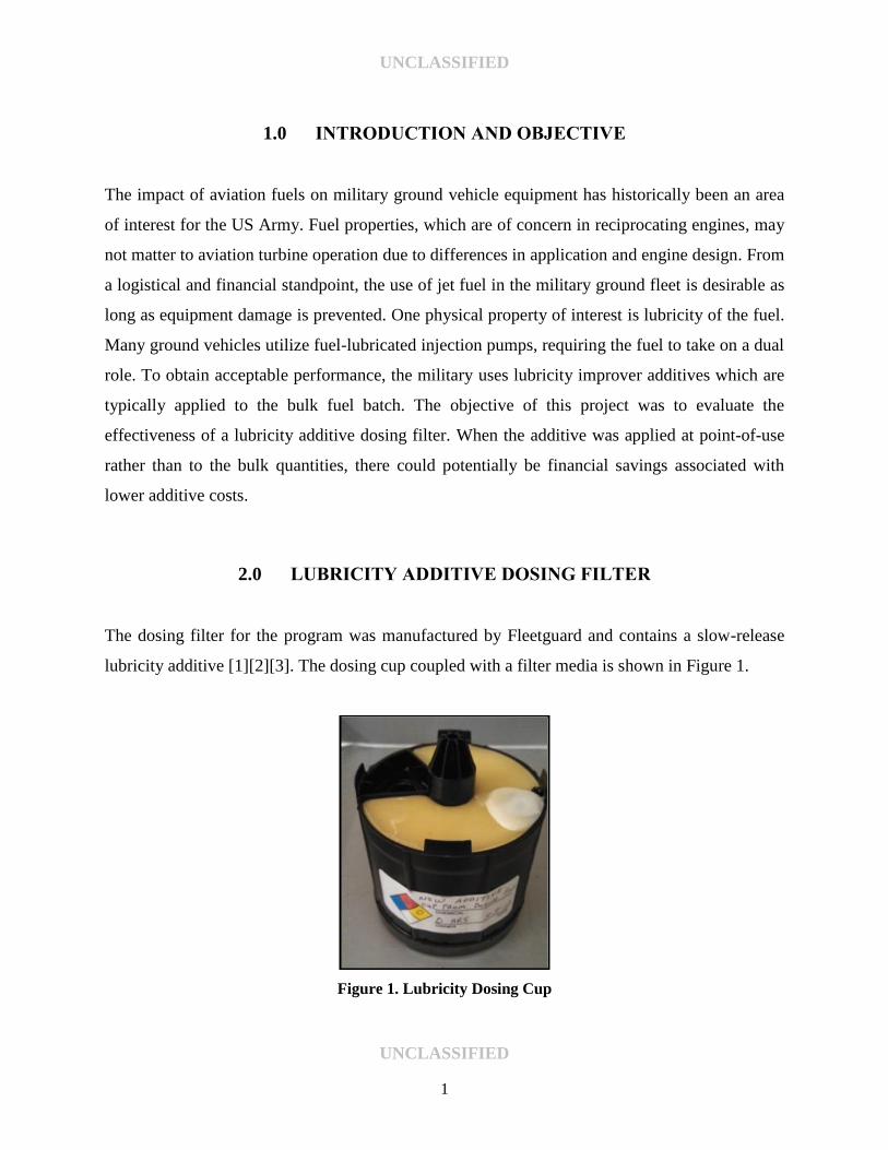
2.0 LUBRICITY ADDITIVE DOSING FILTER
The dosing filter for the program was manufactured by Fleetguard and contains a slow-release
lubricity additive [1][2][3]. The dosing cup coupled with a filter media is shown in Figure 1.
Figure 1. Lubricity Dosing Cup
UNCLASSIFIED
UNCLASSIFIED
2
The additive was offered in three filter options for different flow rates and filtration size
requirements. Two options contained the additive in liquid form, while the third option held the
additive in a waxy substrate for slow release. All three options were registered under the same
EPA diesel fuel additive code.
The lubricity additive dosing filter manufacturer has reported on additive release rate [1]. The
lubricity additive release rate was similar in Jet A, US and Japanese Kerosene and US DF2. The
release rate increased linearly with increasing temperatures up to 140 F. As the fuel passed over
the waxy barrier, as seen on the top of the cup in Figure 1, some of the fluid passed through and
displaced the additive within the doser.
Fluid exited the cup through the center hole visible on the top of the middle cone. Under normal
operation, as the concentration of the additive within the cup was reduced, the viscosity of the
fluid within the cup also decreased and allowed for a faster dispersion into the fuel flow path.
Installation was accomplished using a standard spin-on filter head that was intended for
mounting on a vehicle frame rail or other non-engine mounted location. Cummins had reported
that the additive release rate during a fluid evaluation was linear from the start of test to
500 hours with approximately 30% of additive remaining at 500 hours [2].
While it was desirable to directly measure and track the concentration of the lubricity dosing
additive in various fuels, it was found that the compound was a long-chain acid molecule (very
similar to DCI-4A) which was not easily distinguishable from various hydrocarbons found in
fuels. Therefore, in place of a direct measurement method, the additive DCI-4A was dissolved at
various concentration levels in representative fuels and run through standard lubricity tests to
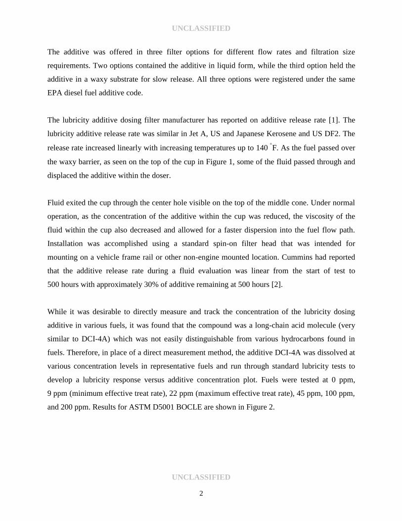
develop a lubricity response versus additive concentration plot. Fuels were tested at 0 ppm,
9 ppm (minimum effective treat rate), 22 ppm (maximum effective treat rate), 45 ppm, 100 ppm,
and 200 ppm. Results for ASTM D5001 BOCLE are shown in Figure 2.
UNCLASSIFIED
UNCLASSIFIED
3
Figure 2. BOCLE Response to Additive Concentration
The BOCLE test method showed a noticeable response to the addition of the additive over small
treat rates in the Jet A and SPK fuels. The ULSD fuel had very little change in the value of Wear
Scar Diameter (WSD), changing from 0.52 mm at no additive concentration to 0.49 mm at the
maximum treat rate of 22 ppm. This change in WSD value was within the repeatability of the test
and therefore, ULSD is considered to have no response to lubricity additive. It should be noted
that the response for all the fuels beyond the maximum effective treat rate was not significant.
Results for ASTM D6079 HFRR for all the three fuels are shown in Figure 3.
UNCLASSIFIED
UNCLASSIFIED
4
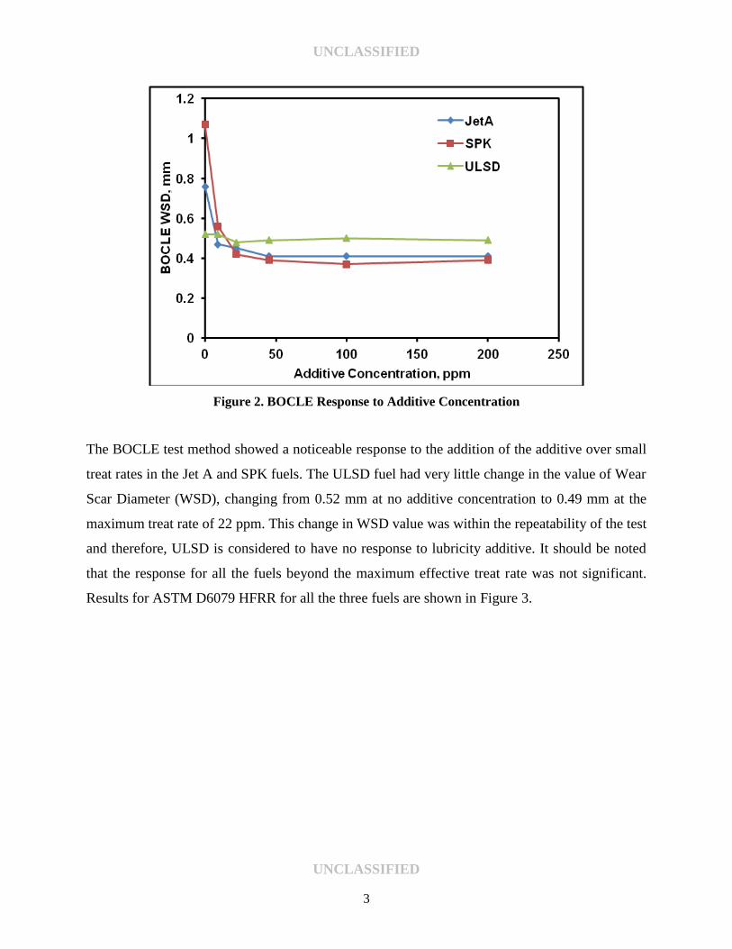
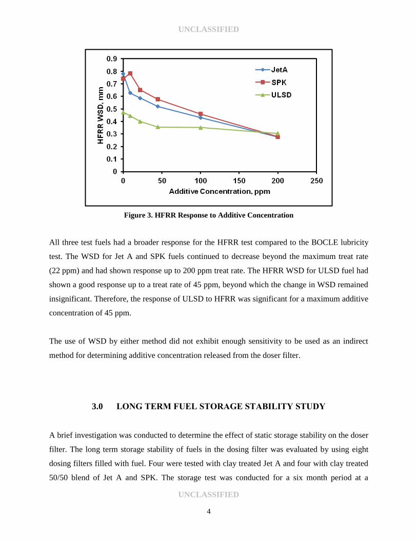
Figure 3. HFRR Response to Additive Concentration
All three test fuels had a broader response for the HFRR test compared to the BOCLE lubricity
test. The WSD for Jet A and SPK fuels continued to decrease beyond the maximum treat rate
(22 ppm) and had shown response up to 200 ppm treat rate. The HFRR WSD for ULSD fuel had
shown a good response up to a treat rate of 45 ppm, beyond which the change in WSD remained
insignificant. Therefore, the response of ULSD to HFRR was significant for a maximum additive
concentration of 45 ppm.
The use of WSD by either method did not exhibit enough sensitivity to be used as an indirect
method for determining additive concentration released from the doser filter.
3.0 LONG TERM FUEL STORAGE STABILITY STUDY
A brief investigation was conducted to determine the effect of static storage stability on the doser
filter. The long term storage stability of fuels in the dosing filter was evaluated by using eight
dosing filters filled with fuel. Four were tested with clay treated Jet A and four with clay treated
50/50 blend of Jet A and SPK. The storage test was conducted for a six month period at a
UNCLASSIFIED
UNCLASSIFIED
5
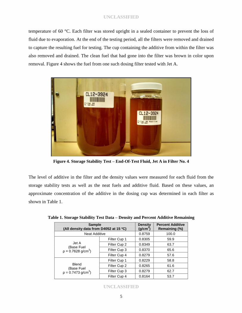
temperature of 60 °C. Each filter was stored upright in a sealed container to prevent the loss of
fluid due to evaporation. At the end of the testing period, all the filters were removed and drained
to capture the resulting fuel for testing. The cup containing the additive from within the filter was
also removed and drained. The clean fuel that had gone into the filter was brown in color upon
removal. Figure 4 shows the fuel from one such dosing filter tested with Jet A.
Figure 4. Storage Stability Test – End-Of-Test Fluid, Jet A in Filter No. 4
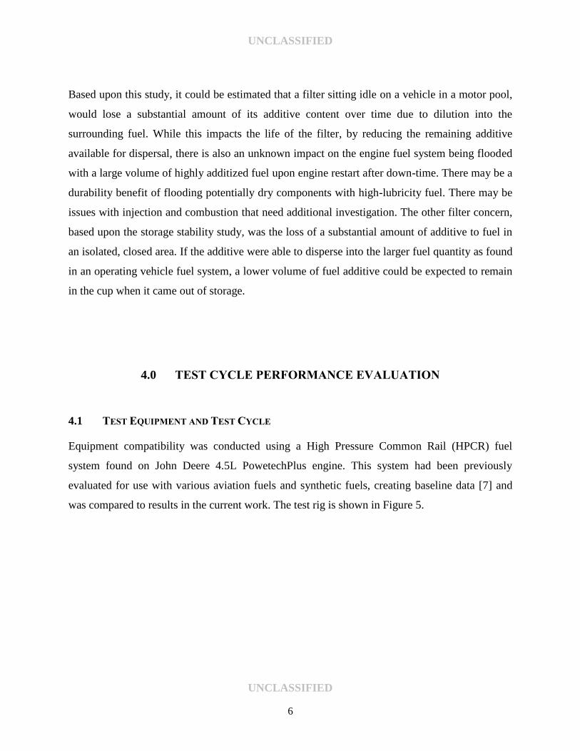
The level of additive in the filter and the density values were measured for each fluid from the
storage stability tests as well as the neat fuels and additive fluid. Based on these values, an
approximate concentration of the additive in the dosing cup was determined in each filter as
shown in Table 1.
Table 1. Storage Stability Test Data – Density and Percent Additive Remaining
Sample (All density data from D4052 at 15 ºC)
Density (g/cm
3)
Percent Additive Remaining (%)
Neat Additive 0.8759 100.0
Jet A (Base Fuel
ρ = 0.7628 g/cm3)
Filter Cup 1 0.8305 59.9
Filter Cup 2 0.8349 63.7
Filter Cup 3 0.8370 65.6
Filter Cup 4 0.8279 57.6
Blend (Base Fuel
ρ = 0.7473 g/cm3)
Filter Cup 1 0.8229 58.8
Filter Cup 2 0.8265 61.6
Filter Cup 3 0.8279 62.7
Filter Cup 4 0.8164 53.7
UNCLASSIFIED
UNCLASSIFIED
6
Based upon this study, it could be estimated that a filter sitting idle on a vehicle in a motor pool,
would lose a substantial amount of its additive content over time due to dilution into the
surrounding fuel. While this impacts the life of the filter, by reducing the remaining additive
available for dispersal, there is also an unknown impact on the engine fuel system being flooded
with a large volume of highly additized fuel upon engine restart after down-time. There may be a
durability benefit of flooding potentially dry components with high-lubricity fuel. There may be
issues with injection and combustion that need additional investigation. The other filter concern,
based upon the storage stability study, was the loss of a substantial amount of additive to fuel in
an isolated, closed area. If the additive were able to disperse into the larger fuel quantity as found
in an operating vehicle fuel system, a lower volume of fuel additive could be expected to remain
in the cup when it came out of storage.
4.0 TEST CYCLE PERFORMANCE EVALUATION
4.1 TEST EQUIPMENT AND TEST CYCLE
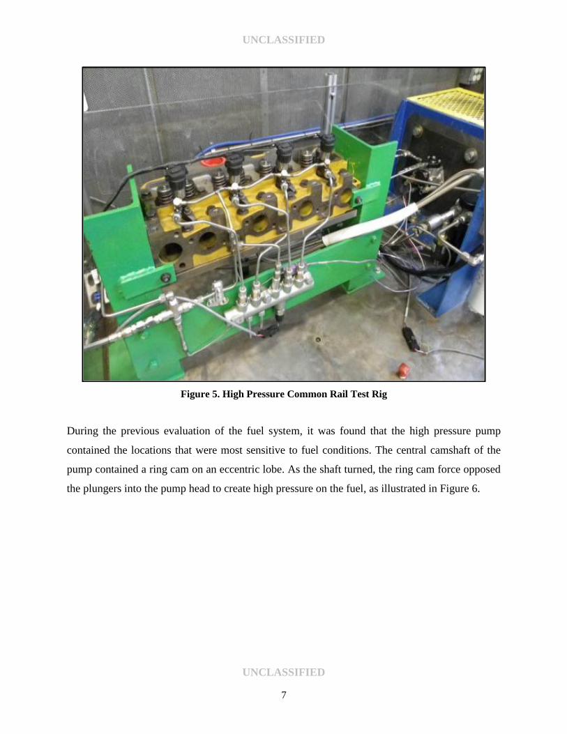
Equipment compatibility was conducted using a High Pressure Common Rail (HPCR) fuel
system found on John Deere 4.5L PowetechPlus engine. This system had been previously
evaluated for use with various aviation fuels and synthetic fuels, creating baseline data [7] and
was compared to results in the current work. The test rig is shown in Figure 5.
UNCLASSIFIED
UNCLASSIFIED
7
Figure 5. High Pressure Common Rail Test Rig
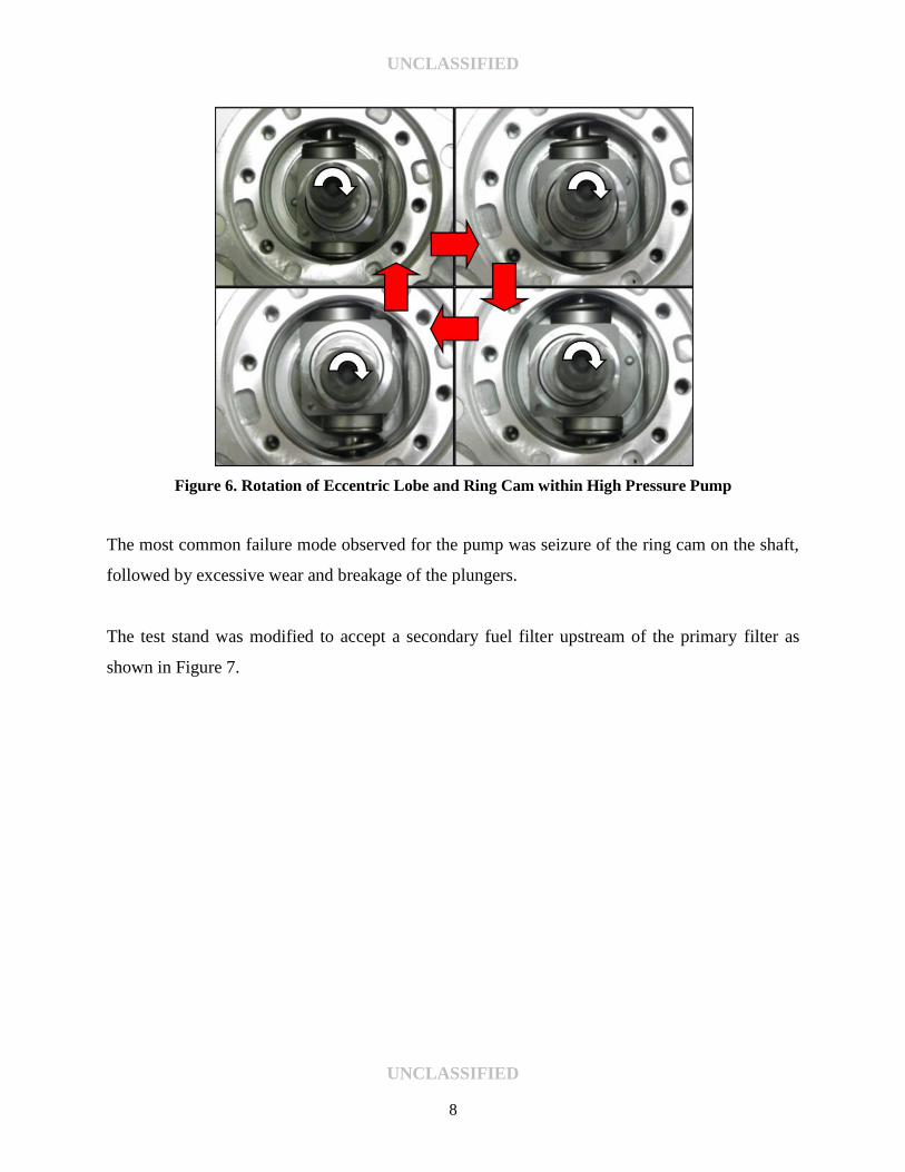
During the previous evaluation of the fuel system, it was found that the high pressure pump
contained the locations that were most sensitive to fuel conditions. The central camshaft of the
pump contained a ring cam on an eccentric lobe. As the shaft turned, the ring cam force opposed
the plungers into the pump head to create high pressure on the fuel, as illustrated in Figure 6.
UNCLASSIFIED
UNCLASSIFIED
8
Figure 6. Rotation of Eccentric Lobe and Ring Cam within High Pressure Pump
The most common failure mode observed for the pump was seizure of the ring cam on the shaft,
followed by excessive wear and breakage of the plungers.
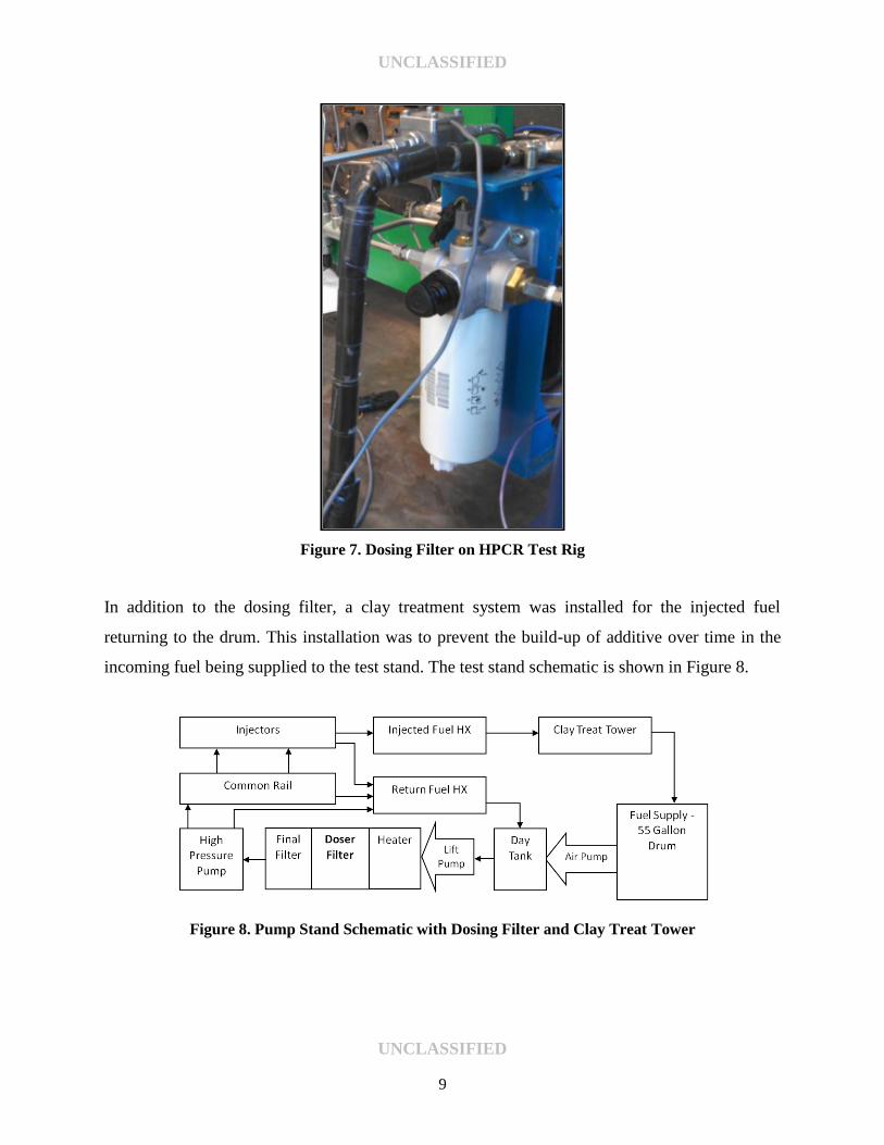
The test stand was modified to accept a secondary fuel filter upstream of the primary filter as
shown in Figure 7.
UNCLASSIFIED
UNCLASSIFIED
9
Figure 7. Dosing Filter on HPCR Test Rig
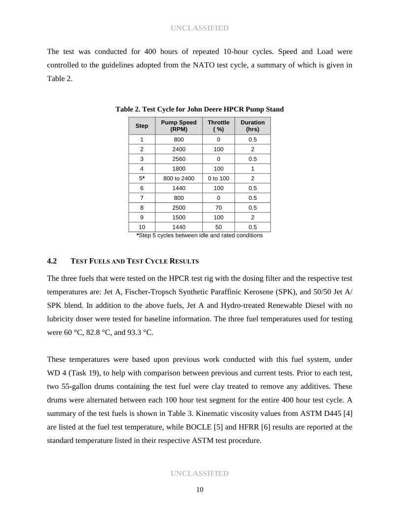
In addition to the dosing filter, a clay treatment system was installed for the injected fuel
returning to the drum. This installation was to prevent the build-up of additive over time in the
incoming fuel being supplied to the test stand. The test stand schematic is shown in Figure 8.
Figure 8. Pump Stand Schematic with Dosing Filter and Clay Treat Tower
UNCLASSIFIED
UNCLASSIFIED
10
The test was conducted for 400 hours of repeated 10-hour cycles. Speed and Load were
controlled to the guidelines adopted from the NATO test cycle, a summary of which is given in
Table 2.
Table 2. Test Cycle for John Deere HPCR Pump Stand
Step Pump Speed
(RPM) Throttle
( %) Duration
(hrs)
1 800 0 0.5
2 2400 100 2
3 2560 0 0.5
4 1800 100 1
5* 800 to 2400 0 to 100 2
6 1440 100 0.5
7 800 0 0.5
8 2500 70 0.5
9 1500 100 2
10 1440 50 0.5
*Step 5 cycles between idle and rated conditions
4.2 TEST FUELS AND TEST CYCLE RESULTS
The three fuels that were tested on the HPCR test rig with the dosing filter and the respective test
temperatures are: Jet A, Fischer-Tropsch Synthetic Paraffinic Kerosene (SPK), and 50/50 Jet A/
SPK blend. In addition to the above fuels, Jet A and Hydro-treated Renewable Diesel with no
lubricity doser were tested for baseline information. The three fuel temperatures used for testing
were 60 °C, 82.8 °C, and 93.3 °C.
These temperatures were based upon previous work conducted with this fuel system, under
WD 4 (Task 19), to help with comparison between previous and current tests. Prior to each test,
two 55-gallon drums containing the test fuel were clay treated to remove any additives. These
drums were alternated between each 100 hour test segment for the entire 400 hour test cycle. A
summary of the test fuels is shown in Table 3. Kinematic viscosity values from ASTM D445 [4]
are listed at the fuel test temperature, while BOCLE [5] and HFRR [6] results are reported at the
standard temperature listed in their respective ASTM test procedure.
UNCLASSIFIED
UNCLASSIFIED
11
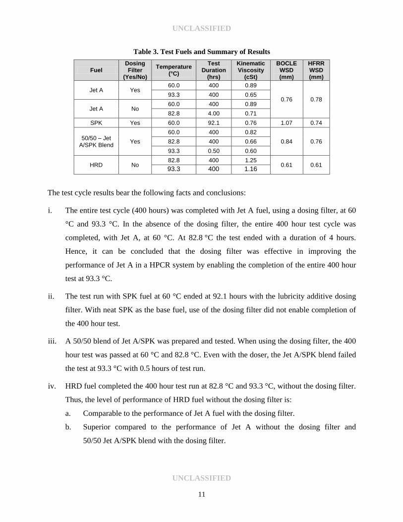
Table 3. Test Fuels and Summary of Results
Fuel Dosing Filter
(Yes/No)
Temperature (°C)
Test Duration
(hrs)
Kinematic Viscosity
(cSt)
BOCLE WSD (mm)
HFRR WSD (mm)
Jet A Yes 60.0 400 0.89
0.76 0.78 93.3 400 0.65
Jet A No 60.0 400 0.89
82.8 4.00 0.71
SPK Yes 60.0 92.1 0.76 1.07 0.74
50/50 – Jet A/SPK Blend
Yes
60.0 400 0.82
0.84 0.76 82.8 400 0.66
93.3 0.50 0.60
HRD No 82.8 400 1.25
0.61 0.61 93.3 400 1.16
The test cycle results bear the following facts and conclusions:
i. The entire test cycle (400 hours) was completed with Jet A fuel, using a dosing filter, at 60
°C and 93.3 °C. In the absence of the dosing filter, the entire 400 hour test cycle was
completed, with Jet A, at 60 °C. At 82.8 °C the test ended with a duration of 4 hours.
Hence, it can be concluded that the dosing filter was effective in improving the
performance of Jet A in a HPCR system by enabling the completion of the entire 400 hour
test at 93.3 °C.
ii. The test run with SPK fuel at 60 °C ended at 92.1 hours with the lubricity additive dosing
filter. With neat SPK as the base fuel, use of the dosing filter did not enable completion of
the 400 hour test.
iii. A 50/50 blend of Jet A/SPK was prepared and tested. When using the dosing filter, the 400
hour test was passed at 60 °C and 82.8 °C. Even with the doser, the Jet A/SPK blend failed
the test at 93.3 °C with 0.5 hours of test run.
iv. HRD fuel completed the 400 hour test run at 82.8 °C and 93.3 °C, without the dosing filter.
Thus, the level of performance of HRD fuel without the dosing filter is:
a. Comparable to the performance of Jet A fuel with the dosing filter.
b. Superior compared to the performance of Jet A without the dosing filter and
50/50 Jet A/SPK blend with the dosing filter.
UNCLASSIFIED
UNCLASSIFIED
12
c. The higher viscosity of the HRD fuel may be a factor affecting HPCR pump wear
performance compared to Jet A and SPK blend fuels.
4.3 COMPARISON WITH TEST CYCLE RESULTS FROM WD 04 (TASK XIX)
Table 4, lists the fuels, test temperatures, lubricity additive treat rates, and test cycle durations for
tests conducted using a High Pressure Common Rail (HPCR) fuel system found on John Deere
4.5L PowertechPlus engine under WD 04 (Task XIX). It should be noted that all the fuels were
clay treated prior to treatment with DCI-4A.
Table 4. Test Cycle Results for Equipment Compatibility Studies in WD 04 (Task XIX) [7]*
Fuel DCI-4A
Treat rate (ppm)
Temperature (°C)
Test Duration (hrs)
Jet A 9 60.0 400
93.3 400
SPK 9 60.0 400
93.3 4
50/50 – Jet
A/SPK Blend
9 60.0 400
22.5 82.8 400
9 93.3 4
22.5 93.3 4
*No lubricity dosing filter was used for WD 04 (Task XIX). ULSD result is not listed in the above table, since this fuel was not tested under WD 04.
A comparison between test cycle results achieved using the dosing filter (in Table 3) and without
the dosing filter (in Table 4), bears the following facts and conclusions:
i. Jet A fuel when used without the dosing filter and no lubricity additive treatment was able
to complete the 400 hour test only at 60 °C. Jet A treated with 9ppm of DCI-4A was able to
complete the 400 hour test for all three test temperatures. When a lubricity dosing filter was
used for the test run with clay treated Jet A, the fuel passed all three test temperatures. This
implies that either DCI-4A at a minimum treat rate (9 ppm) or a lubricity dosing filter is
required for successful test run at 82.8 °C and 93.3 °C, for Jet A fuel.
UNCLASSIFIED
UNCLASSIFIED
13
ii. SPK fuel, at a minimum treat rate of 9 ppm with DCI-4A, and no lubricity additive dosing
filter, passed the test at 60 °C and failed at 93.3 °C (4 hours). Clay treated SPK fuel failed
the test at 60 °C with the use of a lubricity additive dosing filter. Hence, it can be
concluded that the dosing filter was ineffective in improving the performance of SPK fuel.
iii. Fuel blend containing 50/50 Jet A/SPK passed the test run with a minimum treat rate (9
ppm) at 60 °C and a maximum treat rate (22.5 ppm) at 82.8 °C, while the fuel blend failed
the test at 93.3 °C at both minimum and maximum treat rates. When a lubricity dosing
filter was used, the fuel blend passed the test at 60 °C and 82.8 °C, while it failed at 93.3 °C
with a run time of 0.5 hours. There was no apparent difference in component wear
observed for the 82.8 °C test, for the blend treated at max DCI-4A versus the blend with
the use of dosing filter. It is concluded that the effect of lubricity additive dosing filter is
comparable to DCI-4A treat rates and that neither method can improve the performance of
the fuel blend at 93.3 °C.
5.0 FUEL – COMPONENT COMPATIBILITY EVALUATION
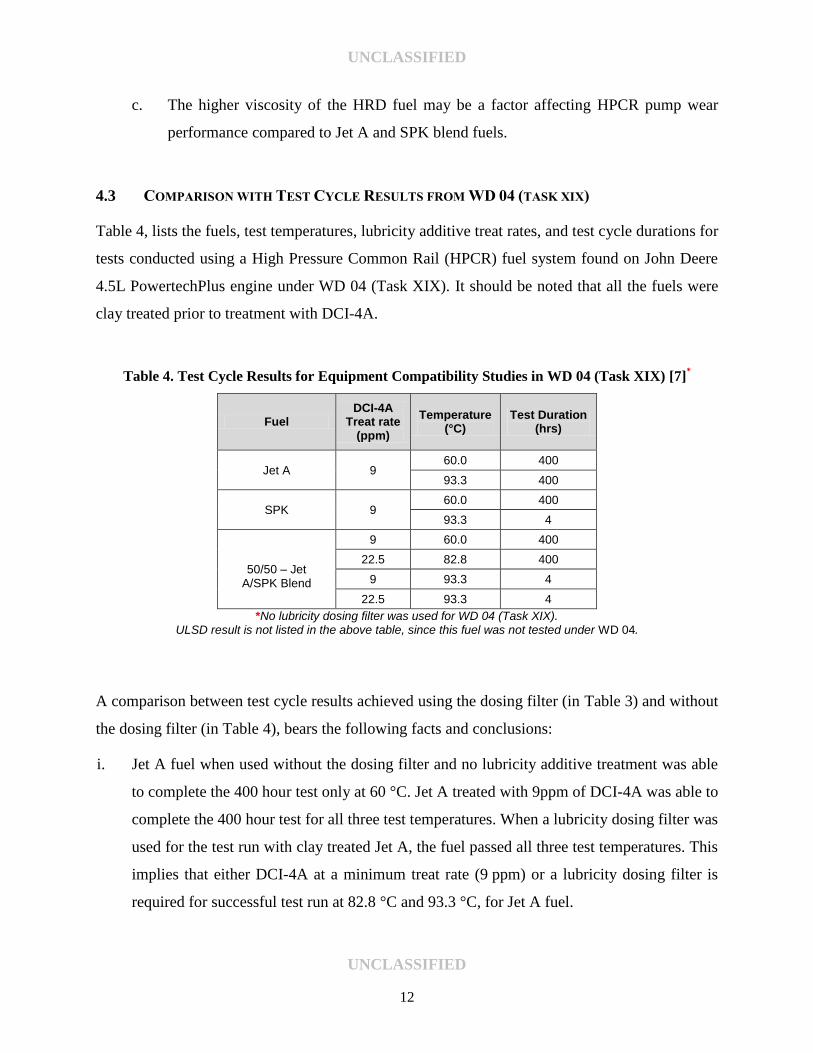
5.1 IMPACT OF JET A ON COMPONENT COMPATIBILITY
The filter’s impact on Jet A was of considerable value and interest due to its probable future
usage in military ground vehicle applications. Previous testing had shown Jet A to provide
acceptable protection to the system when treated with the minimum level, 9 ppm of lubricity
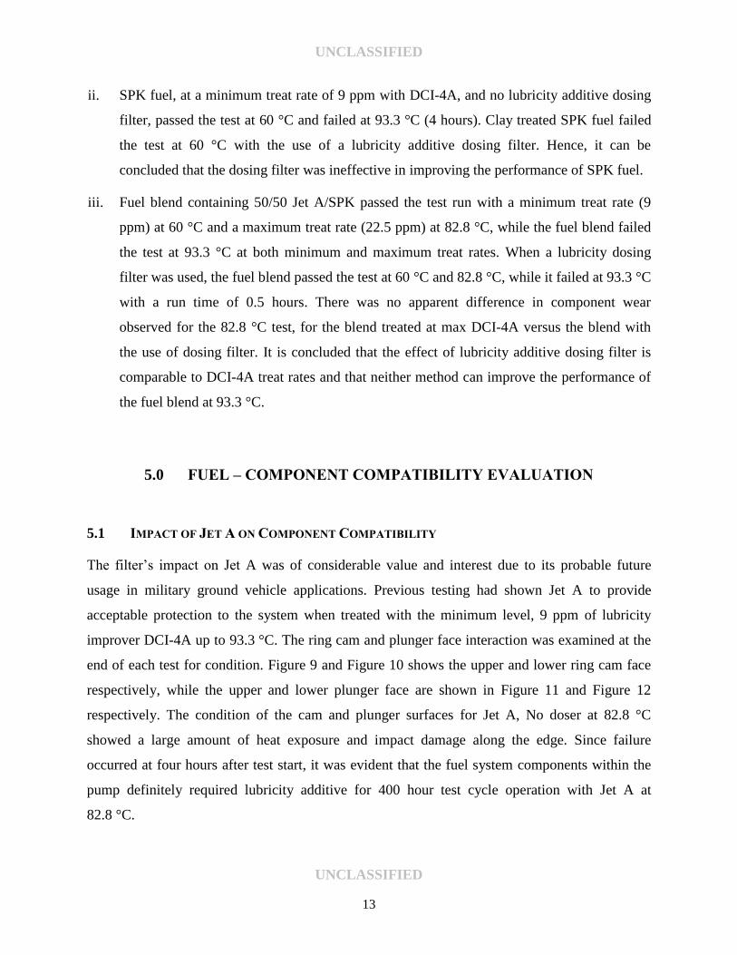
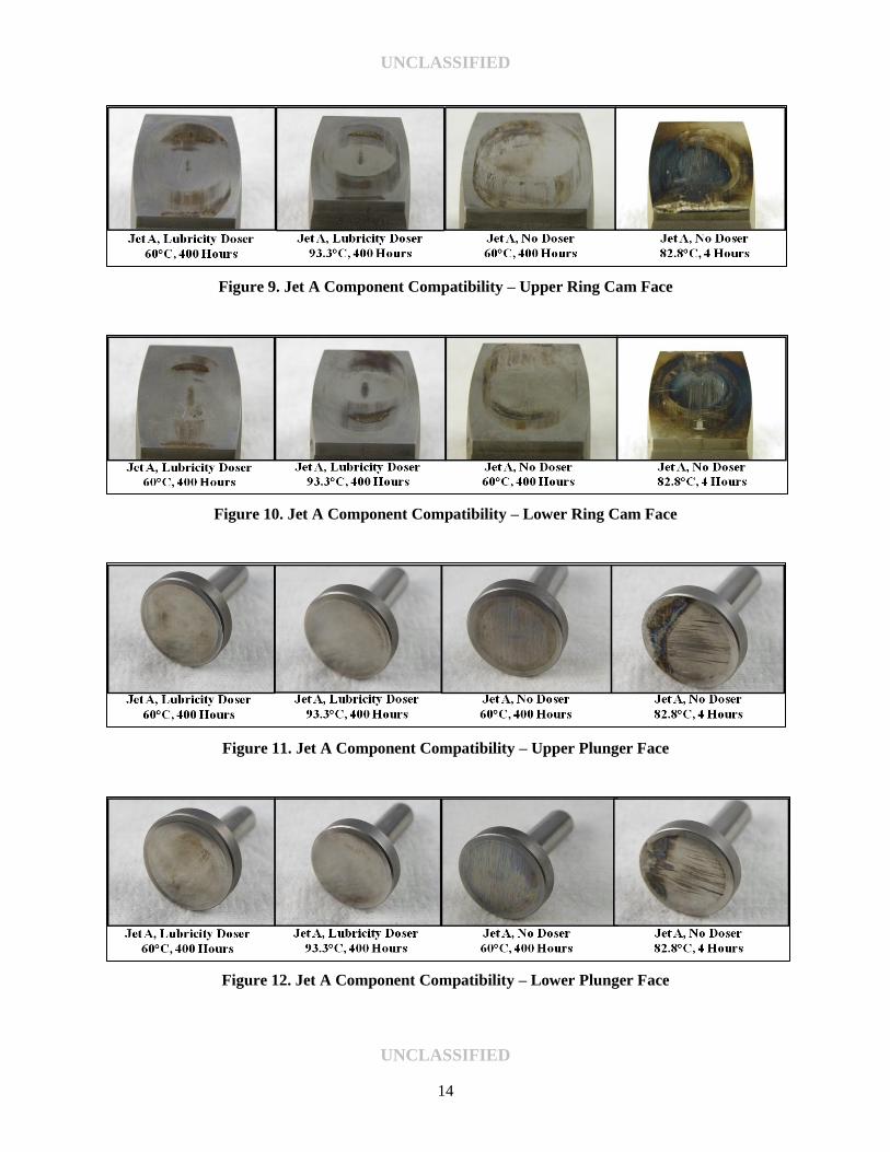
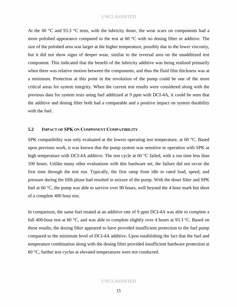
improver DCI-4A up to 93.3 °C. The ring cam and plunger face interaction was examined at the
end of each test for condition. Figure 9 and Figure 10 shows the upper and lower ring cam face
respectively, while the upper and lower plunger face are shown in Figure 11 and Figure 12
respectively. The condition of the cam and plunger surfaces for Jet A, No doser at 82.8 °C
showed a large amount of heat exposure and impact damage along the edge. Since failure
occurred at four hours after test start, it was evident that the fuel system components within the
pump definitely required lubricity additive for 400 hour test cycle operation with Jet A at
82.8 °C.
UNCLASSIFIED
UNCLASSIFIED
14
Figure 9. Jet A Component Compatibility – Upper Ring Cam Face
Figure 10. Jet A Component Compatibility – Lower Ring Cam Face
Figure 11. Jet A Component Compatibility – Upper Plunger Face
Figure 12. Jet A Component Compatibility – Lower Plunger Face
UNCLASSIFIED
UNCLASSIFIED
15
At the 60 °C and 93.3 °C tests, with the lubricity doser, the wear scars on components had a
more polished appearance compared to the test at 60 °C with no dosing filter or additive. The
size of the polished area was larger at the higher temperature, possibly due to the lower viscosity,
but it did not show signs of deeper wear, similar to the reversal area on the unadditized test
component. This indicated that the benefit of the lubricity additive was being realized primarily
when there was relative motion between the components, and thus the fluid film thickness was at
a minimum. Protection at this point in the revolution of the pump could be one of the more
critical areas for system integrity. When the current test results were considered along with the
previous data for system tests using fuel additized at 9 ppm with DCI-4A, it could be seen that
the additive and dosing filter both had a comparable and a positive impact on system durability
with the fuel.
5.2 IMPACT OF SPK ON COMPONENT COMPATIBILITY
SPK compatibility was only evaluated at the lowest operating test temperature, at 60 °C. Based
upon previous work, it was known that the pump system was sensitive to operation with SPK at
high temperature with DCI-4A additive. The test cycle at 60 °C failed, with a run time less than
100 hours. Unlike many other evaluations with this hardware set, the failure did not occur the
first time through the test run. Typically, the first ramp from idle to rated load, speed, and
pressure during the fifth phase had resulted in seizure of the pump. With the doser filter and SPK
fuel at 60 °C, the pump was able to survive over 90 hours, well beyond the 4 hour mark but short
of a complete 400 hour test.
In comparison, the same fuel treated at an additive rate of 9 ppm DCI-4A was able to complete a
full 400-hour test at 60 °C, and was able to complete slightly over 4 hours at 93.3 °C. Based on
these results, the dosing filter appeared to have provided insufficient protection to the fuel pump
compared to the minimum level of DCI-4A additive. Upon establishing the fact that the fuel and
temperature combination along with the dosing filter provided insufficient hardware protection at
60 °C, further test cycles at elevated temperatures were not conducted.
UNCLASSIFIED
UNCLASSIFIED
16
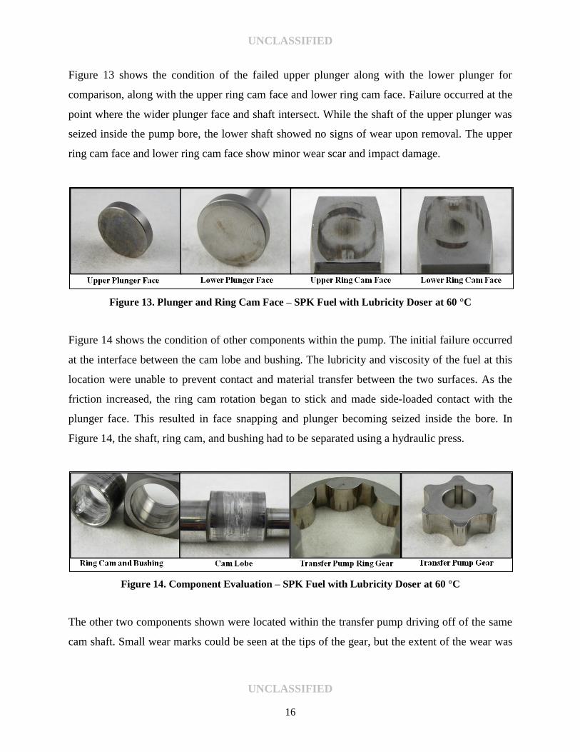
Figure 13 shows the condition of the failed upper plunger along with the lower plunger for
comparison, along with the upper ring cam face and lower ring cam face. Failure occurred at the
point where the wider plunger face and shaft intersect. While the shaft of the upper plunger was
seized inside the pump bore, the lower shaft showed no signs of wear upon removal. The upper
ring cam face and lower ring cam face show minor wear scar and impact damage.
Figure 13. Plunger and Ring Cam Face – SPK Fuel with Lubricity Doser at 60 °C
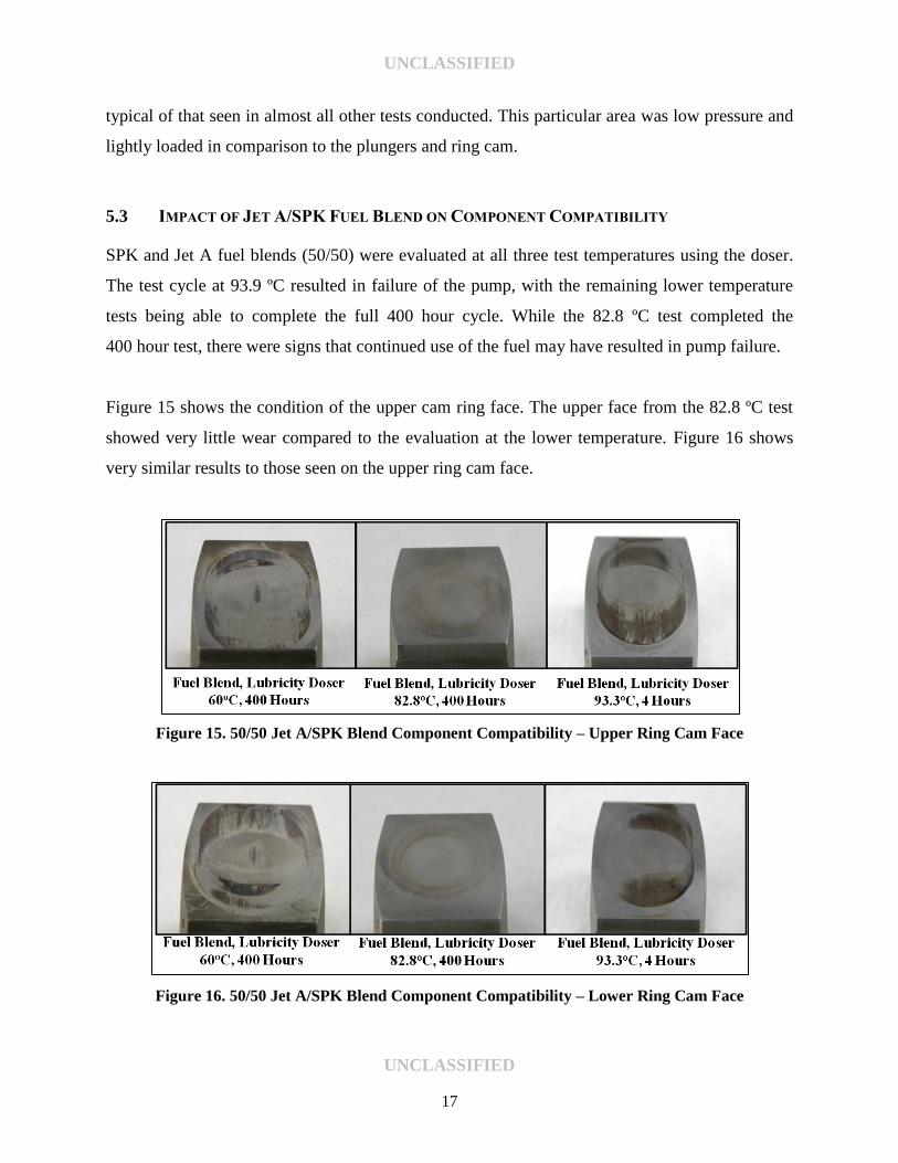
Figure 14 shows the condition of other components within the pump. The initial failure occurred
at the interface between the cam lobe and bushing. The lubricity and viscosity of the fuel at this
location were unable to prevent contact and material transfer between the two surfaces. As the
friction increased, the ring cam rotation began to stick and made side-loaded contact with the
plunger face. This resulted in face snapping and plunger becoming seized inside the bore. In
Figure 14, the shaft, ring cam, and bushing had to be separated using a hydraulic press.
Figure 14. Component Evaluation – SPK Fuel with Lubricity Doser at 60 °C
The other two components shown were located within the transfer pump driving off of the same
cam shaft. Small wear marks could be seen at the tips of the gear, but the extent of the wear was
UNCLASSIFIED
UNCLASSIFIED
17
typical of that seen in almost all other tests conducted. This particular area was low pressure and
lightly loaded in comparison to the plungers and ring cam.
5.3 IMPACT OF JET A/SPK FUEL BLEND ON COMPONENT COMPATIBILITY
SPK and Jet A fuel blends (50/50) were evaluated at all three test temperatures using the doser.
The test cycle at 93.9 ºC resulted in failure of the pump, with the remaining lower temperature
tests being able to complete the full 400 hour cycle. While the 82.8 ºC test completed the
400 hour test, there were signs that continued use of the fuel may have resulted in pump failure.
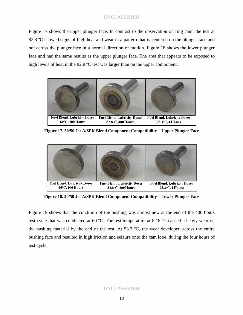
Figure 15 shows the condition of the upper cam ring face. The upper face from the 82.8 ºC test
showed very little wear compared to the evaluation at the lower temperature. Figure 16 shows
very similar results to those seen on the upper ring cam face.
Figure 15. 50/50 Jet A/SPK Blend Component Compatibility – Upper Ring Cam Face
Figure 16. 50/50 Jet A/SPK Blend Component Compatibility – Lower Ring Cam Face
UNCLASSIFIED
UNCLASSIFIED
18
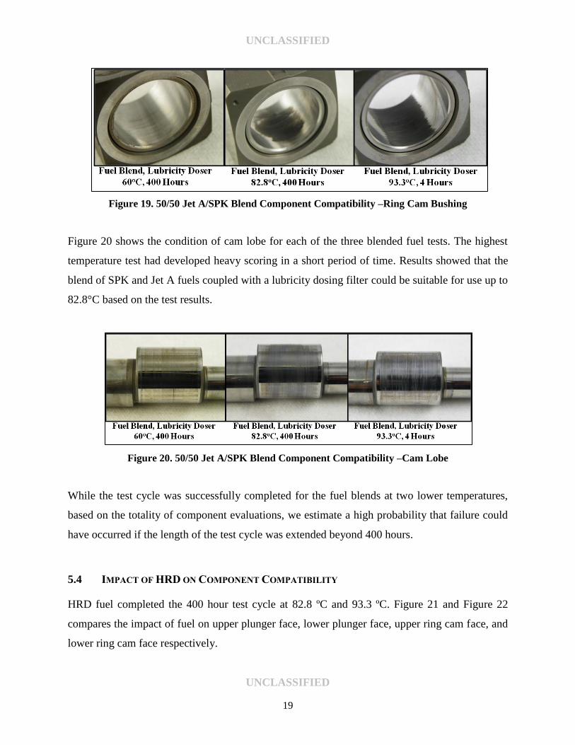
Figure 17 shows the upper plunger face. In contrast to the observation on ring cam, the test at
82.8 ºC showed signs of high heat and wear in a pattern that is centered on the plunger face and
not across the plunger face in a normal direction of motion. Figure 18 shows the lower plunger
face and had the same results as the upper plunger face. The area that appears to be exposed to
high levels of heat in the 82.8 ºC test was larger than on the upper component.
Figure 17. 50/50 Jet A/SPK Blend Component Compatibility – Upper Plunger Face
Figure 18. 50/50 Jet A/SPK Blend Component Compatibility – Lower Plunger Face
Figure 19 shows that the condition of the bushing was almost new at the end of the 400 hours
test cycle that was conducted at 60 ºC. The test temperature at 82.8 ºC caused a heavy wear on
the bushing material by the end of the test. At 93.3 ºC, the wear developed across the entire
bushing face and resulted in high friction and seizure onto the cam lobe, during the four hours of
test cycle.
UNCLASSIFIED
UNCLASSIFIED
19
Figure 19. 50/50 Jet A/SPK Blend Component Compatibility –Ring Cam Bushing
Figure 20 shows the condition of cam lobe for each of the three blended fuel tests. The highest
temperature test had developed heavy scoring in a short period of time. Results showed that the
blend of SPK and Jet A fuels coupled with a lubricity dosing filter could be suitable for use up to
82.8°C based on the test results.
Figure 20. 50/50 Jet A/SPK Blend Component Compatibility –Cam Lobe
While the test cycle was successfully completed for the fuel blends at two lower temperatures,
based on the totality of component evaluations, we estimate a high probability that failure could
have occurred if the length of the test cycle was extended beyond 400 hours.
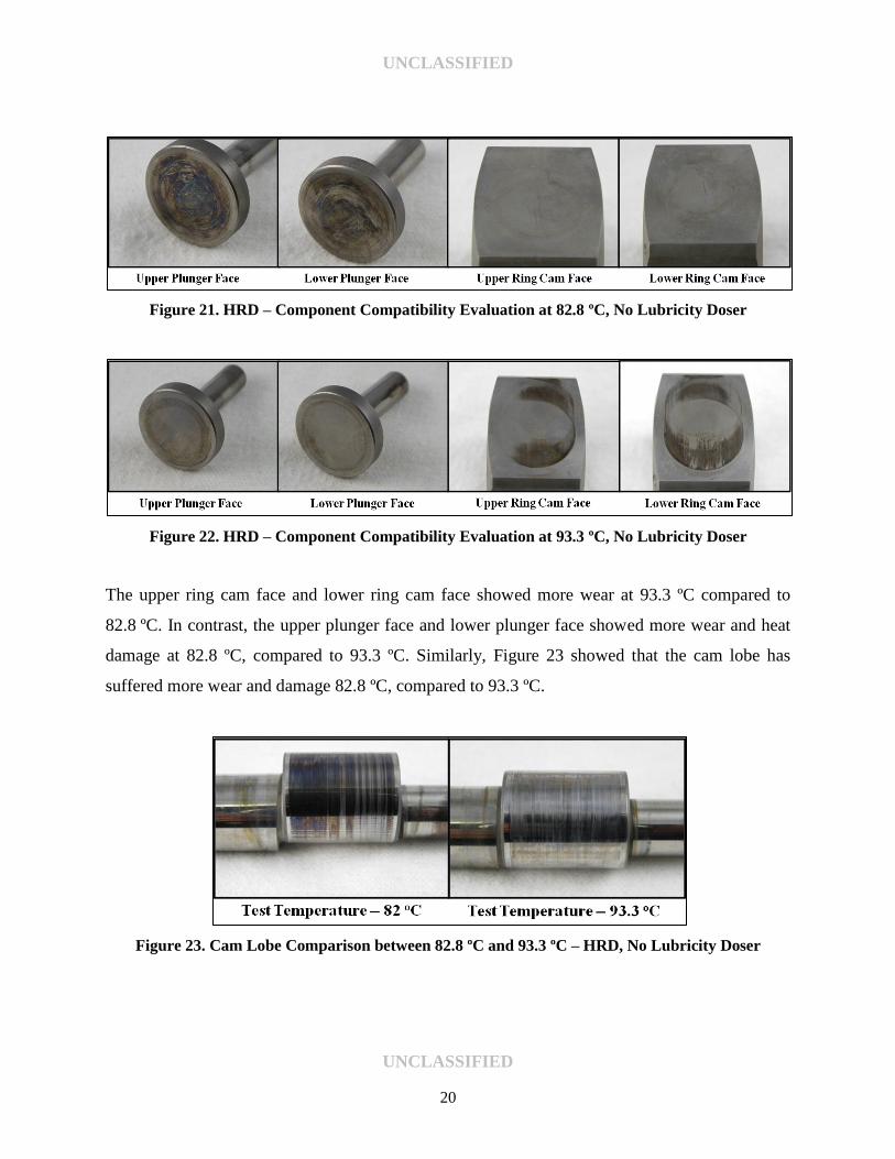
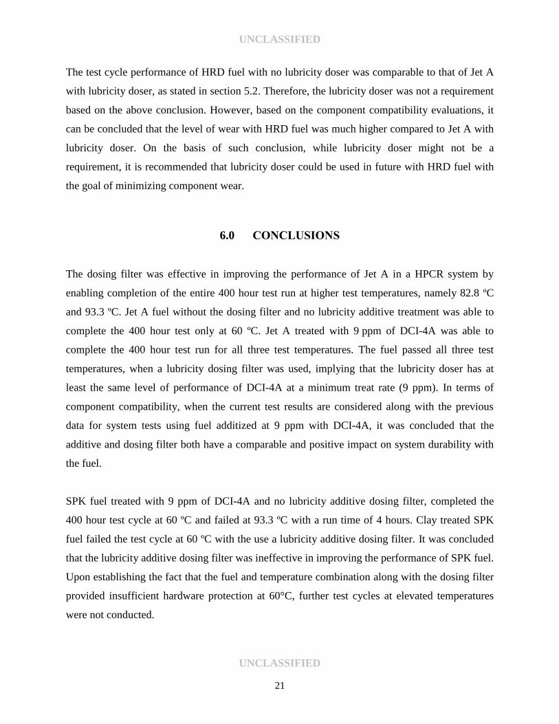
5.4 IMPACT OF HRD ON COMPONENT COMPATIBILITY
HRD fuel completed the 400 hour test cycle at 82.8 ºC and 93.3 ºC. Figure 21 and Figure 22
compares the impact of fuel on upper plunger face, lower plunger face, upper ring cam face, and
lower ring cam face respectively.
UNCLASSIFIED
UNCLASSIFIED
20
Figure 21. HRD – Component Compatibility Evaluation at 82.8 ºC, No Lubricity Doser
Figure 22. HRD – Component Compatibility Evaluation at 93.3 ºC, No Lubricity Doser
The upper ring cam face and lower ring cam face showed more wear at 93.3 ºC compared to
82.8 ºC. In contrast, the upper plunger face and lower plunger face showed more wear and heat
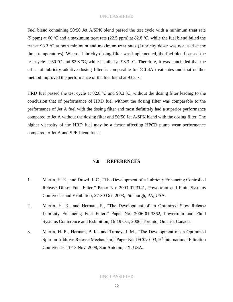
damage at 82.8 ºC, compared to 93.3 ºC. Similarly, Figure 23 showed that the cam lobe has
suffered more wear and damage 82.8 ºC, compared to 93.3 ºC.
Figure 23. Cam Lobe Comparison between 82.8 ºC and 93.3 ºC – HRD, No Lubricity Doser
UNCLASSIFIED
UNCLASSIFIED
21
The test cycle performance of HRD fuel with no lubricity doser was comparable to that of Jet A
with lubricity doser, as stated in section 5.2. Therefore, the lubricity doser was not a requirement
based on the above conclusion. However, based on the component compatibility evaluations, it
can be concluded that the level of wear with HRD fuel was much higher compared to Jet A with
lubricity doser. On the basis of such conclusion, while lubricity doser might not be a
requirement, it is recommended that lubricity doser could be used in future with HRD fuel with
the goal of minimizing component wear.
6.0 CONCLUSIONS
The dosing filter was effective in improving the performance of Jet A in a HPCR system by
enabling completion of the entire 400 hour test run at higher test temperatures, namely 82.8 ºC
and 93.3 ºC. Jet A fuel without the dosing filter and no lubricity additive treatment was able to
complete the 400 hour test only at 60 ºC. Jet A treated with 9 ppm of DCI-4A was able to
complete the 400 hour test run for all three test temperatures. The fuel passed all three test
temperatures, when a lubricity dosing filter was used, implying that the lubricity doser has at
least the same level of performance of DCI-4A at a minimum treat rate (9 ppm). In terms of
component compatibility, when the current test results are considered along with the previous
data for system tests using fuel additized at 9 ppm with DCI-4A, it was concluded that the
additive and dosing filter both have a comparable and positive impact on system durability with
the fuel.
SPK fuel treated with 9 ppm of DCI-4A and no lubricity additive dosing filter, completed the
400 hour test cycle at 60 ºC and failed at 93.3 ºC with a run time of 4 hours. Clay treated SPK
fuel failed the test cycle at 60 ºC with the use a lubricity additive dosing filter. It was concluded
that the lubricity additive dosing filter was ineffective in improving the performance of SPK fuel.
Upon establishing the fact that the fuel and temperature combination along with the dosing filter
provided insufficient hardware protection at 60°C, further test cycles at elevated temperatures
were not conducted.
UNCLASSIFIED
UNCLASSIFIED
22
Fuel blend containing 50/50 Jet A/SPK blend passed the test cycle with a minimum treat rate
(9 ppm) at 60 ºC and a maximum treat rate (22.5 ppm) at 82.8 ºC, while the fuel blend failed the
test at 93.3 ºC at both minimum and maximum treat rates (Lubricity doser was not used at the
three temperatures). When a lubricity dosing filter was implemented, the fuel blend passed the
test cycle at 60 ºC and 82.8 ºC, while it failed at 93.3 ºC. Therefore, it was concluded that the
effect of lubricity additive dosing filter is comparable to DCI-4A treat rates and that neither
method improved the performance of the fuel blend at 93.3 ºC.
HRD fuel passed the test cycle at 82.8 ºC and 93.3 ºC, without the dosing filter leading to the
conclusion that of performance of HRD fuel without the dosing filter was comparable to the
performance of Jet A fuel with the dosing filter and most definitely had a superior performance
compared to Jet A without the dosing filter and 50/50 Jet A/SPK blend with the dosing filter. The
higher viscosity of the HRD fuel may be a factor affecting HPCR pump wear performance
compared to Jet A and SPK blend fuels.
7.0 REFERENCES
1. Martin, H. R., and Drozd, J. C., “The Development of a Lubricity Enhancing Controlled
Release Diesel Fuel Filter,” Paper No. 2003-01-3141, Powertrain and Fluid Systems
Conference and Exhibition, 27-30 Oct, 2003, Pittsburgh, PA, USA.
2. Martin, H. R., and Herman, P., “The Development of an Optimized Slow Release
Lubricity Enhancing Fuel Filter,” Paper No. 2006-01-3362, Powertrain and Fluid
Systems Conference and Exhibition, 16-19 Oct, 2006, Toronto, Ontario, Canada.
3. Martin, H. R., Herman, P. K., and Turney, J. M., “The Development of an Optimized
Spin-on Additive Release Mechanism,” Paper No. IFC09-003, 9th
International Filtration
Conference, 11-13 Nov, 2008, San Antonio, TX, USA.
UNCLASSIFIED
UNCLASSIFIED
23
4. ASTM Standard D445, 2011, “Standard Test Method for Kinematic Viscosity of
Transparent and Opaque Liquids (and Calculation of Dynamic Viscosity),” ASTM
International, West Conshohocken, PA, 2011, DOI: 10.1520/D6079-11.
5. ASTM Standard D5001, 2010, “Standard Test Method for Measurement of Lubricity of
Aviation Turbine Fuels by the Ball-on-Cylinder Lubricity Evaluator (BOCLE),” ASTM
International, West Conshohocken, PA, 2010, DOI: 10.1520/D5001-10.
6. ASTM Standard D6079, 2011, “Standard Test Method for Evaluating Lubricity of
Diesel Fuels by the High-Frequency Reciprocating Rig (HFRR),” ASTM International,
West Conshohocken, PA, 2011, DOI: 10.1520/D6079-11.
7. Warden, R.W., Frame, E.A., and Yost, D. M., “Evaluation of Future Fuels in a High
Pressure Common Rail System Part 3 – John Deere 4.5L PowerTech Plus,” Interim
Report TFLRF No. 433, March 2013.
UNCLASSIFIED
UNCLASSIFIED
A-1
APPENDIX A.
FUEL LUBRICITY MEASUREMENTS
UNCLASSIFIED
UNCLASSIFIED
A-2
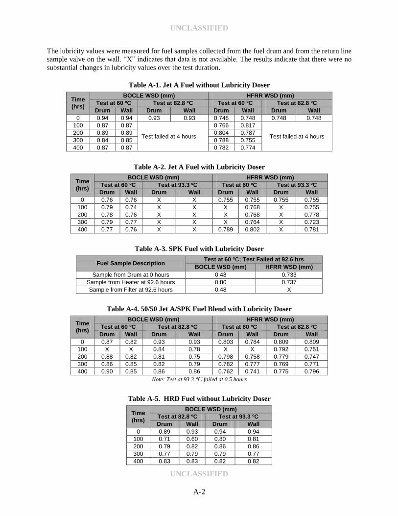
The lubricity values were measured for fuel samples collected from the fuel drum and from the return line
sample valve on the wall. “X” indicates that data is not available. The results indicate that there were no
substantial changes in lubricity values over the test duration.
Table A-1. Jet A Fuel without Lubricity Doser
Time
(hrs)
BOCLE WSD (mm) HFRR WSD (mm)
Test at 60 ºC Test at 82.8 ºC Test at 60 ºC Test at 82.8 ºC
Drum Wall Drum Wall Drum Wall Drum Wall
0 0.94 0.94 0.93 0.93 0.748 0.748 0.748 0.748
100 0.87 0.87
Test failed at 4 hours
0.766 0.817
Test failed at 4 hours 200 0.89 0.89 0.804 0.787
300 0.84 0.85 0.788 0.755
400 0.87 0.87 0.782 0.774
Table A-2. Jet A Fuel with Lubricity Doser
Time
(hrs)
BOCLE WSD (mm) HFRR WSD (mm)
Test at 60 ºC Test at 93.3 ºC Test at 60 ºC Test at 93.3 ºC
Drum Wall Drum Wall Drum Wall Drum Wall
0 0.76 0.76 X X 0.755 0.755 0.755 0.755
100 0.79 0.74 X X X 0.768 X 0.755
200 0.78 0.76 X X X 0.768 X 0.778
300 0.79 0.77 X X X 0.764 X 0.723
400 0.77 0.76 X X 0.789 0.802 X 0.781
Table A-3. SPK Fuel with Lubricity Doser
Fuel Sample Description Test at 60 ºC; Test Failed at 92.6 hrs
BOCLE WSD (mm) HFRR WSD (mm)
Sample from Drum at 0 hours 0.48 0.733
Sample from Heater at 92.6 hours 0.80 0.737
Sample from Filter at 92.6 hours 0.48 X
Table A-4. 50/50 Jet A/SPK Fuel Blend with Lubricity Doser
Time
(hrs)
BOCLE WSD (mm) HFRR WSD (mm)
Test at 60 ºC Test at 82.8 ºC Test at 60 ºC Test at 82.8 ºC
Drum Wall Drum Wall Drum Wall Drum Wall
0 0.87 0.82 0.93 0.93 0.803 0.784 0.809 0.809
100 X X 0.84 0.78 X X 0.792 0.751
200 0.88 0.82 0.81 0.75 0.798 0.758 0.779 0.747
300 0.86 0.85 0.82 0.79 0.782 0.777 0.769 0.771
400 0.90 0.85 0.86 0.86 0.762 0.741 0.775 0.796
Note: Test at 93.3 °C failed at 0.5 hours
Table A-5. HRD Fuel without Lubricity Doser
Time
(hrs)
BOCLE WSD (mm)
Test at 82.8 ºC Test at 93.3 ºC
Drum Wall Drum Wall
0 0.89 0.93 0.94 0.94
100 0.71 0.60 0.80 0.81
200 0.79 0.82 0.86 0.86
300 0.77 0.79 0.79 0.77
400 0.83 0.83 0.82 0.82