Embed Size (px)
Citation preview

First Solar Product, Inc. Tel: 636-537-5888 18102 Chesterfield Airport Rd, Unit O Fax: 636-489-0509 Chesterfield MO 63005
Solar Hot Water System Installation Manual - Split Systems This manual explains how to install a system of evacuated tubes with the collector panels separated from the storage tank. Systems described use First Solar Products’ SunChaser evacuated tube collectors, either for service hot water or swimming pool heating. In the case of swimming pool heating, locations that never freeze may forgo the solar hot water tank, the heat exchanger and expansion vessel. Any location that freezes or has minerals in the water should use a heat exchanger to avoid collector damage. Content 1. Important Information………………………………………………………………………....2 2. Unpack and inspect…………………………………………………………………………...4 3. Plumbing………………………………………………………………………………………..5 4. Stagnation and Overheating………………………………………………………………….6 5. Structure of heat pipe with glass tube………………………………………………………..7 6. Frame Installation……………………………………………………………………………. .8 7. Installation collector……………………………………………………………………………8 8. Circuit installation illustration…………………………………………………………………11 9. Medium liquid filling inside the pipeline……………………………………………………...22 10. Maintenance…………………………………………………………………………………..25 11. Precautions……………………………………………………………………………………26 12. Installation Checklist…………………………………………………………………………27

First Solar Product, Inc. Tel: 636-537-5888 18102 Chesterfield Airport Rd, Unit O Fax: 636-489-0509 Chesterfield MO 63005
2
System Overview: The split or closed loop solar hot water systems are comprised of 3 major components: the collector(s), storage tank with built in heat exchanger and work station with pump & controller. Solar collector The solar collector converts solar radiation into heat and transfers the energy to a freeze proof solar liquid. Temperatures in a solar collector can reach more than 200 Celsius or 395 Fahrenheit. Solar circulation pump and controller A circulation pump ensures heat transfer from collector to storage tank. Automatic control starts the pump as soon as the collector is warmer than the tank. The control unit also contains various safety devices such as manometer, safety valves, release pipes and an expansion vessel. This accounts for the differences in volume resulting from changing temperatures in the heat transfer liquid. Collector tubes: The selective absorber coating on the inner glass tube results in maximum radiation absorption while the vacuum between inner and out tubes results in almost complete elimination of convection and conduction heat losses. In a u-tube model, the heat is transferred from the absorber on the inner glass tube surface to a metal cylindrical fin, which holds a copper pipe through which the water flows. In the water in tube model, the water to be heated comes in direct contact with the inner glass tube, which results in greater heat transfer, but in much lower working pressures. Storage Tank Solar energy is almost never available at the same time it is needed. Most domestic hot water is used in the morning and evening when the sun is not yet shining or has already set. Different models of hot water storage tanks therefore act as mediums between solar energy production and consumption. Copper spiral coils inside the tank serve as the heat exchanger.
1. Important Information 1.1. Local standards Installation must be completed in accordance with relevant local standards and regulations. 1.2. Qualified Installer Installation must be completed by qualified plumbing professionals or certified solar thermal installers. Certified solar thermal installers can be located from NABCEP

First Solar Product, Inc. Tel: 636-537-5888 18102 Chesterfield Airport Rd, Unit O Fax: 636-489-0509 Chesterfield MO 63005
3
website: http://www.nabcep.org. 1.3. Pressure and Temperature Control and Relief Solar loop should be designed for normal operation at﹤500kpa (72 PSI) via use of a pressure limiting (pressure reduction) valve on the mains cold supply line. System design must provide means for allowing pressure release at no more than 800kpa (113psi) and hot water dumping from the solar loop or storage tank once the temperature reaches 99°C(210°F)。It is recommended that the lever on the pressure and temperature relief valve (PTRV) be operated once every 6 months to ensure reliable operation. It is important to raise and lower the lever gently. 1.4. Water quality Water in direct flow through the manifold header must meet potable water requirements as well as the following conditions: Total dissolved solids ﹤ 600mg/litre or p.p.m Total hardness ﹤ 200mg/litre or p.p.m Chloride ﹤ 250mg/litre or p.p.m Magnesium ﹤ 10mg/litre or p.p.m In areas with “hard” water (﹥200ppm),line scale may from inside in header pipe. In such regions, it is advisable to in stall water softening device to ensure long term efficient operation of the collector, or to install a closed loop solar hot water system. For closed loop systems, glycol/water mix must meet the above requirements. In addition, glycol/water mix should be changed periodically to prevent fluid from becoming acidic. 1.5. Metallic corrosion Both copper and stainless steel are susceptible to corrosion when high concentrations of chloride are present. When used for heating spa or poor water, levels of free chorine must not exceed 2ppm. Warranty on the header when the system is used for spa or pool heating is 2years. Chloride level present in most reticulated pubic potable water supplies is safe for use in the collector provided that there is no use of bore water in the reticulated supply. 1.6. Freeze Protection Freeze protection should be incorporated into the system by use of a” low manifold temperature” setting on the solar controller, which turns on the pump if the manifold drops below a preset level (eg5°C/41°F)。A closed loop solar hot water system using a glycol-water mix is automatically freeze free. Evacuated tubes are not susceptible to damage in cold weather, and heat pipes are protected against damage caused by freezing conditions.

First Solar Product, Inc. Tel: 636-537-5888 18102 Chesterfield Airport Rd, Unit O Fax: 636-489-0509 Chesterfield MO 63005
4
1.7. Hail resistance The glass evacuated tubes are surprisingly strong and able to handle significant impact stresses once installed. Testing and impact stress modeling proves that the tubes are able to withstand impact from hail up to 25mm/1” in diameter when installed at angle of 40°or greater. The ability of the evacuated tubes to withstand impact form hail is greatly influenced by the angle of impact. Therefore installing the collectors at low angles do reduce their impact resistance. However, even when lying flat, impact by hail up to 20mm (3/4”) in size will not cause breakage. It is recommended that in areas prone to large hail (﹥20mm or 3/4”) the solar collector should be installed at an angle of 40°or greater to provide optimum protection. As many populated areas in the world fall within the latitude of ±30-70°, this angle is generally a common installation anyway. If in the unlikely circumstance that a tube should become broken, it can be easily replaced in a matter of minutes. The solar collector can still function properly with one or more broken tubes. However a reduction in heat output will result (depending upon how many tube are broken). 1.8 System design and installation
2. Unpack and Inspection 2.1. Tube inspection Open the tube box (es), which contain both evacuated tubes and heat pipes. Check to make sure the evacuated tubes are all intact and bottom of each tube is still silver. If a tube has a white or clear bottom, it is damaged and should be replaced. Each evacuated tube contains a pair of metal heat transfer fins. Do not expose the tubes to sunlight until you are ready to install them. Otherwise the copper condenser for the heat pipe may become hot enough to cause burn. 2.2. Heat pipes If heat pipes are bent during handing, doesn’t worry as they are not easily damaged. Just ensure they are relatively straight before insertion into manifold.
First Solar Product, Inc. Tel: 636-537-5888 18102 Chesterfield Airport Rd, Unit O Fax: 636-489-0509 Chesterfield MO 63005
5
2.3. Frame Unpack the standard frame kit that is packed together with the manifold. Of a flat roof frame or low pitched roof frame is being used, those components are packaged separately from the manifold. It may be necessary to purchase bolts or other fasteners to secure the frame on the ground or flat roof top.
3. Plumbing 3.1 Plumbing Connection Once the frame has been mounted and the manifold attached, the manifold header may be connected to the system plumbing. 3.2 Choice of Piping Material Pipe size recommendation: For a solar installation with pipe work of total length 30 to 50 meters, the following dimensions are recommended for the flow and return pipe work: Less than 36 tubes 12 mm or ½ inch-possible, but recommend ¾ inch. Up to 90 tubes 22 mm or ¾ inch Up to 120 tubes 128 mm or 1 inch More than 120 tubes – use parallel branches of 1 inch each. Pipe work should be insulated with ¾ inch minimum high temperature pipe insulation, more insulation in more extreme cold environments. For multiple manifold installations, the recommended maximum number of manifolds that should be connected in series is five 12-tube solar panels. For more panels, use parallel pipe runs. 13mm or 15mm OD copper piping is generally used for most solar collector installations. As the flow rate is slow, a large diameter pipe is unnecessary and will only increase system costs and heat loss. Copper or stainless steel flex tubing are recommended because they are easy to bend and pass through the roof. The end of the flexible pipe is either 1/2″for 3/4 BSP thread, and can accept standard male BSP thread fittings for connection to copper pipe. 3.3 Pressure Levels Regardless of the installation configuration, pressure release values, expansion vessels and/or other pressure control devices must be installed. The solar loop should be designed to operate at no more than 800kPa (PRV may be 850 kPa). (800kPa=8bar=116psi) For installation where mains pressure water is used, the system should ideally be designed to operate at a pressure of ﹤500kPa, achieved

First Solar Product, Inc. Tel: 636-537-5888 18102 Chesterfield Airport Rd, Unit O Fax: 636-489-0509 Chesterfield MO 63005
6
by use of a pressure limiting/reduction value. 3.4 Tempering Value It is recommended, and may be required by regulations, that a temperature control device (tempering value) be fit into the hot water pipe between the water heater and bathrooms and en-suites to reduce the risk of scalding. This is achieved by controlling the water temperature to below 50°C/122°F(temperature may be adjustable). 3.5 Temperature Sensor Insertion The solar controller’s temperature sensor should be coated with a thick layer of thermal paste and inserted into the sensor port to the full depth. If the fit is too loose, slide a piece of copper plate or wire in beside the sensor, seal the sensor port opening with silicone sealant to prevent water ingress. Ensure that sensors used on the collector are high temperature rated (up to 250°C/486°F).
4 Stagnation and Overheating Stagnation refers to the condition that occurs when the pump stops running, due to pump failure, power blackout, or as a result of a high tank temperature protection feature built into the controller, which turns the pump off. If a PTRV is installed on collector inlet or outlet the collector will continue to increase in temperature until the limit of the temperature relief valve is reached, at which point hot water will be dumped from the system. If a PTRV is not installed on the collector, steam will form in the header. Eventually some steam may feed back to the storage tank via the return line. The PTRV on the tank will open to release pressure or heat as required. Under such conditions the manifold will normally reach a maximum temperature of around 160°C/320°F. Generally the heat returning from the collector in the form of steam is not enough to affect a continued increase in tank temperature (reheat input﹤tank heat losses) Under normal use stagnation should rarely occur as a result of pump stoppage, since power blackouts normally happen during storms and not clear sunny weather. High tank temperature protection should only occur when hot water is not used for several days(when on holiday),and only during strong periods of sunlight(summer).If leaving the house for an extended period of time(more than 2-3days),it is advisable to cover the collector panel or design the system with a heat dissipation device or alternative use for the heat, thus preventing overheating of the system and collector stagnation. Stagnation of the solar collector will not damage the solar collector, however insulation used on the piping close to the manifold inlet and outlet should be able to withstand temperatures of up to 200°C/395° F.

First Solar Product, Inc. Tel: 636-537-5888 18102 Chesterfield Airport Rd, Unit O Fax: 636-489-0509 Chesterfield MO 63005
7
5. Structure of heat pipe with glass tube
The heat pipe series solar collectors are always connected with existing heating supply device. The selective coating on the inner cover of the evacuated tubes converts solar energy into heat energy and transfers heat to the heat pipes by aluminum fins. The liquid in the heat pipe changes into vapor which rises to the condenser. The heat then passes through the heat exchanger and the vapor becomes liquid, returning to the base of the heat pipe. The heat conducts to the heat transfer liquid (anti-freezing liquid or water) via a copper pipe. This transference of heat into the liquid creates a continuous circulation as long as the collector is heated by the sun.
First Solar Product, Inc. Tel: 636-537-5888 18102 Chesterfield Airport Rd, Unit O Fax: 636-489-0509 Chesterfield MO 63005
8
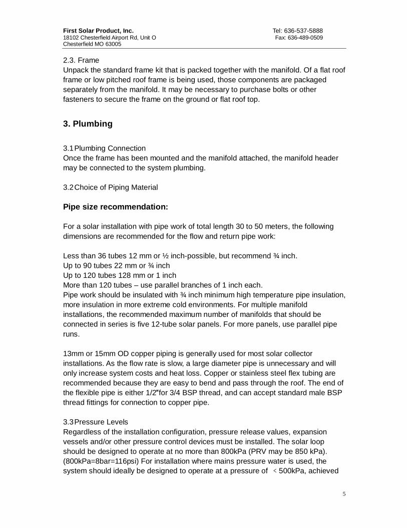
6. Frame Installation
7. Installation of collector 7.1. Collector Direction The collector should face the equator, which if in the Northern hemisphere is due
First Solar Product, Inc. Tel: 636-537-5888 18102 Chesterfield Airport Rd, Unit O Fax: 636-489-0509 Chesterfield MO 63005
9
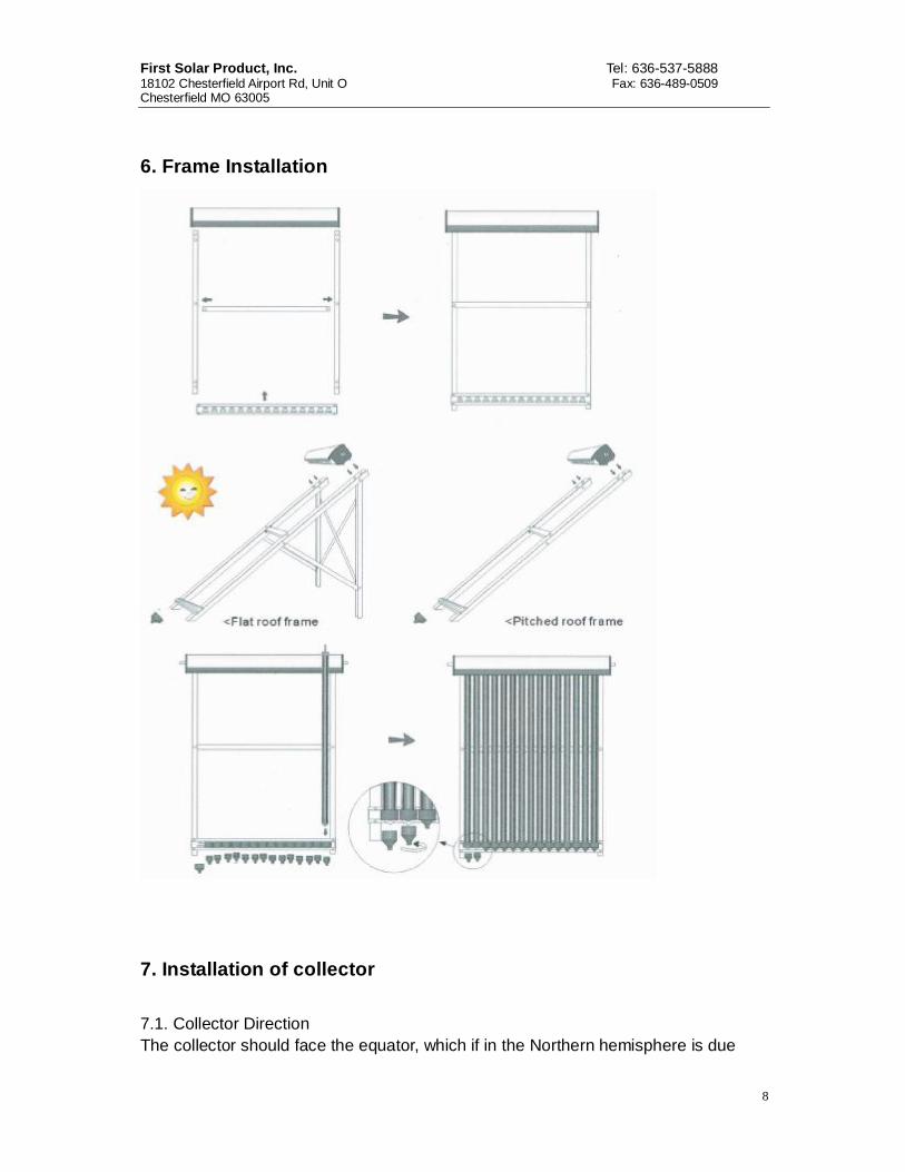
south, and vice versa. Facing the collector in the correct direction and at the correct angle is important to ensure optimal heat output from the collector; however a deviation of up to 10°from due North or South is acceptable, and will have minimal effect on heat output. 7.2. Collector Angle It is common for collectors to be installed at an angle that corresponds to the latitude of the location. Installing at an angle less than 20° is not recommended as the heat pipes perform best in an angle of between 20° and 70°. While adhering to this guideline, an angle of latitude+/-10°is acceptable, and will not greatly reduce solar output. Angles beyond this range may be used, but a decrease in heat output will result. An angle lower than the latitude will increase summer output, while a greater angle will enhance winter output. 7.3. Location The collector should be positioned as close as possible to the storage tank to avoid long pipe runs. Storage tank positioning should therefore consider the location requirements of the solar collector. The storage tank should also be located as close as possible to the most frequent draw off pipe runs. 7.4. Installation of vacuum tubes
Step 1: first install the nylon cap on the bottom track, and then screw off the jacket from the nylon cap. Step 2: put the anti-dust rubber ring on the vacuum tube (mild dish washing liquid and water will be very useful). Apply heat conduction resin on the heat pipe condenser. Step 3: insert the vacuum tube inside the nylon cap. (Be mindful not to touch the

First Solar Product, Inc. Tel: 636-537-5888 18102 Chesterfield Airport Rd, Unit O Fax: 636-489-0509 Chesterfield MO 63005
10
vacuum tube on the ground, or it will be broken). Step 4: Hold the vacuum tube tightly, then insert it inside the opposite hole on the manifold slowly. Step 5: screw the jacket on the nylon cap. System Design Diagrams
Design diagrams for water tank with double heat exchanger (top) and single heat exchanger (bottom)

First Solar Product, Inc. Tel: 636-537-5888 18102 Chesterfield Airport Rd, Unit O Fax: 636-489-0509 Chesterfield MO 63005
11
8. Circuit installation illustration
First Solar Product, Inc. Tel: 636-537-5888 18102 Chesterfield Airport Rd, Unit O Fax: 636-489-0509 Chesterfield MO 63005
12
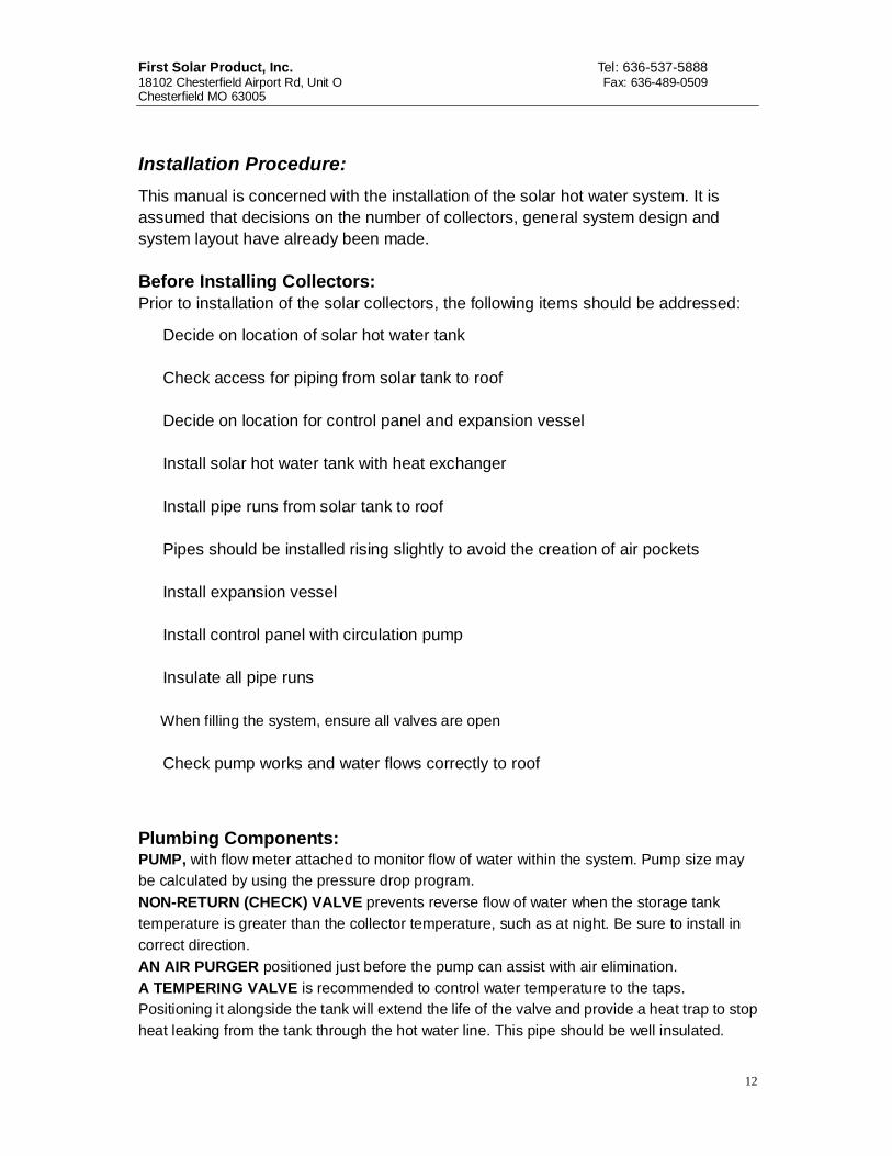
Installation Procedure: This manual is concerned with the installation of the solar hot water system. It is assumed that decisions on the number of collectors, general system design and system layout have already been made. Before Installing Collectors: Prior to installation of the solar collectors, the following items should be addressed:
Decide on location of solar hot water tank
Check access for piping from solar tank to roof
Decide on location for control panel and expansion vessel
Install solar hot water tank with heat exchanger
Install pipe runs from solar tank to roof
Pipes should be installed rising slightly to avoid the creation of air pockets
Install expansion vessel
Install control panel with circulation pump
Insulate all pipe runs
When filling the system, ensure all valves are open
Check pump works and water flows correctly to roof
Plumbing Components: PUMP, with flow meter attached to monitor flow of water within the system. Pump size may be calculated by using the pressure drop program. NON-RETURN (CHECK) VALVE prevents reverse flow of water when the storage tank temperature is greater than the collector temperature, such as at night. Be sure to install in correct direction. AN AIR PURGER positioned just before the pump can assist with air elimination. A TEMPERING VALVE is recommended to control water temperature to the taps. Positioning it alongside the tank will extend the life of the valve and provide a heat trap to stop heat leaking from the tank through the hot water line. This pipe should be well insulated.

First Solar Product, Inc. Tel: 636-537-5888 18102 Chesterfield Airport Rd, Unit O Fax: 636-489-0509 Chesterfield MO 63005
13
EXPANSION VESSEL contains increased water volume in the system due to rise in temperature and hence increased pressure of water.
A PRESSURE RELIEF VALVE and PRESSURE GAUGE monitors the pressure of the system and serves as a safety mechanism to avoid over pressuring of the system. Working pressure is generally 3 bar or 45 psi. An Optional FILLING LOOP, consisting of a flexible hose and stop valve that connects from water mains supply to hose connector and filler valve, with a DOUBLE CHECK VALVE, to stop reverse flow of water into cold mains water supply.
Pipe
Pipe Joining For hot heat transfer fluid pipe, there are not any components connected to this pipe, so it is best to use a single pipe run without any joints with the help of a tube bender. When copper pipe has to be joined,

First Solar Product, Inc. Tel: 636-537-5888 18102 Chesterfield Airport Rd, Unit O Fax: 636-489-0509 Chesterfield MO 63005
14
please use Model C copper pipe union joints (both ends for pipe) to connect both ends. If both pipes of the circulation loop have to be joined, keep the two unions a few centimeters apart in order to make insulation more easily.
Joining copper pipe with unions
Collector-Roof Attachments: Collectors be mounted on any angle roof, but for maximum efficiency, a frame should be made so that the collector angle is about equal to latitude. See the written and pictorial steps below. 1. Select a suitable location on the roof for the collector. In the northern hemisphere, the collector should face due south, at an angle to the ground equal to the latitude. For example, latitude of 49 degrees would use a collector angle of about 49 degrees, plus 10 degrees to give best heating in winter. 2. Remove roof tiles at the corners of an area large enough to fit the collector. 3. Secure a stainless steel band to a rafter using coach screws and washers. 4. Replace the roof tiles, leaving the band protruding (fig 3-4). 5. Secure the collector frame to the bands, or hooks, as installed. 6. Cover the tubes with a blanket if in direct sun. 7. Connect plumbing and turn on pump. Fix the collector on the support frame and leave 60-100 mm distance between two collectors

First Solar Product, Inc. Tel: 636-537-5888 18102 Chesterfield Airport Rd, Unit O Fax: 636-489-0509 Chesterfield MO 63005
15
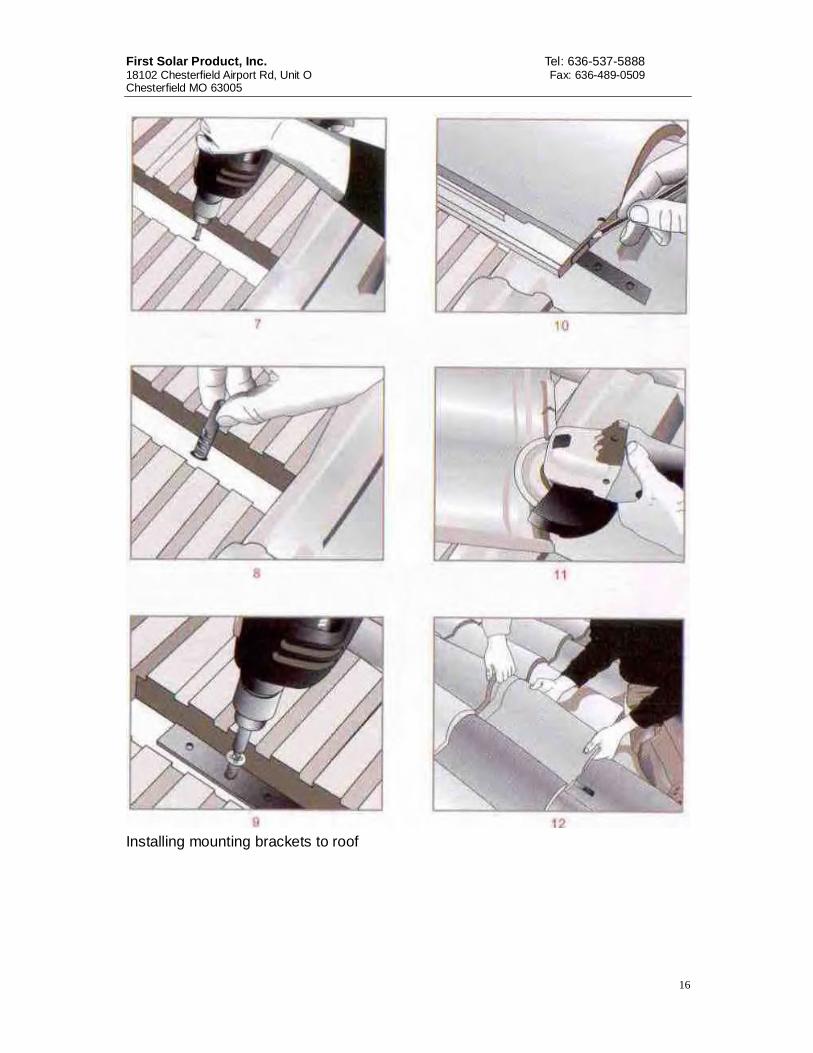
Pictorial Steps to Install Collector Roof Straps:
First Solar Product, Inc. Tel: 636-537-5888 18102 Chesterfield Airport Rd, Unit O Fax: 636-489-0509 Chesterfield MO 63005
16
Installing mounting brackets to roof

First Solar Product, Inc. Tel: 636-537-5888 18102 Chesterfield Airport Rd, Unit O Fax: 636-489-0509 Chesterfield MO 63005
17
Install frame to roof Flat Roof Collector Frame: A flat roof usually means a frame to hold the collector at an angle is needed. Collector angle should be equal to the latitude, so the only place a flat roof will work without a frame is the equator. Some collectors are supplied with frames.

First Solar Product, Inc. Tel: 636-537-5888 18102 Chesterfield Airport Rd, Unit O Fax: 636-489-0509 Chesterfield MO 63005
18
Solar collector frame for flat roof installation To make a frame from angled aluminum, take measurements from your collector and follow the schematic below, or purchase a frame kit for your location.

First Solar Product, Inc. Tel: 636-537-5888 18102 Chesterfield Airport Rd, Unit O Fax: 636-489-0509 Chesterfield MO 63005
19
Flat roof frame construction Temperature sensors On installations that use an electronic controller to turn on the circulation pump, there must be temperature sensors to determine if the collector has useful heat. Collector: On the right cover plate of the collector, there is a hole for the temperature sensor. Push the temperature sensor into the hole and seal it from the rain. The

First Solar Product, Inc. Tel: 636-537-5888 18102 Chesterfield Airport Rd, Unit O Fax: 636-489-0509 Chesterfield MO 63005
20
sensor should be outside of the insulation in order to be replaced easily in case of damage. The temperature at the collector (T1) is displayed on the controller screen, at the bottom. Temperature sensors inside the tank: there are two sensors (T2 and T3) inside the tank. T2 is placed in the middle of the tank; T3 is at the bottom of the tank. T2 is displayed at the upper part of the controller screen, and T3 at the right of the under part of the controller screen. The circulation of the collector loop is controlled by the temperature difference between T1 and T3 if the standard electronic controller is used. Controller Installation Push the temperature sensor into the hole on the collector cover and connect it with temperature sensor connection wire in the tank by STP. Connect the pump with the black wire of tank. Connect the power wire to the power supply. Refer to the controller installation manual for full instructions on setup. Connecting multiple collectors
Two collector headers joined. Seals and gaskets are a potential source of leakage. Selecting good quality is quite critical. At the collectors, pressures and temperatures may be quite high. Seals and gaskets used shall be high-temperature resistant. Silicate rubber gaskets are highly recommended and are provided with some products.

First Solar Product, Inc. Tel: 636-537-5888 18102 Chesterfield Airport Rd, Unit O Fax: 636-489-0509 Chesterfield MO 63005
21
Storage tanks
Solar Water Storage tank with plumbing Place the storage tank in a position that is easy to connect with the water supply and also a position that is easy to supply hot water for the different rooms. On the top of the tank, there is a connection for an air eliminator, or one-way vent valve. On the back side of the standard system tank, there are four inlet and outlets. Connections, in order from top to bottom, are: hot water outlet, circulation loop inlet (warm heat transfer fluid), circulation loop outlet (colder heat transfer fluid), and cold water inlet. On the bottom of the tank, the connection is for drainage. These inlets/outlets shall be connected as following: 1. Connect the air eliminator with the connection on the top; 2. Connect a brass bend with each inlet/outlet connection on the back side of the tank. The bend connected to the hot water outlet shall be installed upward, the bend connected with circulation loop inlet/outlets shall bend left (or right), the bend connected with cold water shall bend downward, and the bend connected with drainage shall bend left or (right); 3. Connect a ball valve with drainage 4. Connect connection pipes with the four inlet/outlet connections on the back side of the tank. Connections are for the hot water outlet, the circulation loop inlet (warmer heat transfer fluid), circulation loop outlet (colder heat transfer fluid), and cold water inlet; Adjust the final position the storage tank. Ensure that the tank is 150mm away from the wall and all connection pipes run parallel with the wall. Note: the drain hole at the bottom of the tank has to be installed with a ball valve. The globe valve can be connected with a 300mm connection pipe for easy installation. The valve shall be blocked to prevent the valve being opened by accident, which will cause the drainage of water.

First Solar Product, Inc. Tel: 636-537-5888 18102 Chesterfield Airport Rd, Unit O Fax: 636-489-0509 Chesterfield MO 63005
22
9. Medium Liquid Filling Inside the Pipeline
Medium liquid filling illustration
First Solar Product, Inc. Tel: 636-537-5888 18102 Chesterfield Airport Rd, Unit O Fax: 636-489-0509 Chesterfield MO 63005
23
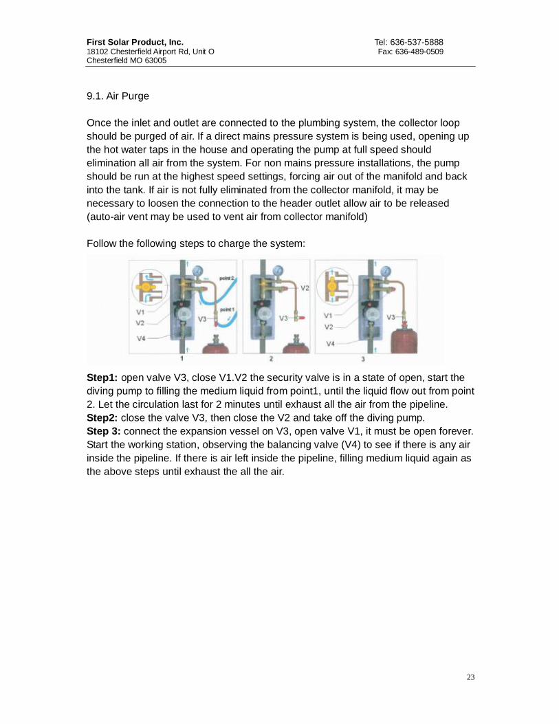
9.1. Air Purge Once the inlet and outlet are connected to the plumbing system, the collector loop should be purged of air. If a direct mains pressure system is being used, opening up the hot water taps in the house and operating the pump at full speed should elimination all air from the system. For non mains pressure installations, the pump should be run at the highest speed settings, forcing air out of the manifold and back into the tank. If air is not fully eliminated from the collector manifold, it may be necessary to loosen the connection to the header outlet allow air to be released (auto-air vent may be used to vent air from collector manifold) Follow the following steps to charge the system:
Step1: open valve V3, close V1.V2 the security valve is in a state of open, start the diving pump to filling the medium liquid from point1, until the liquid flow out from point 2. Let the circulation last for 2 minutes until exhaust all the air from the pipeline. Step2: close the valve V3, then close the V2 and take off the diving pump. Step 3: connect the expansion vessel on V3, open valve V1, it must be open forever. Start the working station, observing the balancing valve (V4) to see if there is any air inside the pipeline. If there is air left inside the pipeline, filling medium liquid again as the above steps until exhaust the all the air.

First Solar Product, Inc. Tel: 636-537-5888 18102 Chesterfield Airport Rd, Unit O Fax: 636-489-0509 Chesterfield MO 63005
24
Sequence of steps for filling and testing fluid loop

First Solar Product, Inc. Tel: 636-537-5888 18102 Chesterfield Airport Rd, Unit O Fax: 636-489-0509 Chesterfield MO 63005
25
Circulation loop cleaning and filling apparatus. 9.2. Plumbing Check Once plumbing is confirmed as leak free and all air have been purged, the heat pipes and evacuated tubes may be installed. 10. Maintenance 10.1. Cleaning Regular rain should keep the evacuated tubes clean. However if the collector becomes dirty, it should be washed with a soft cloth and warm, soapy water or glass cleaning solution. If the tubes are not easily accessible, high pressure water spray is also effective. 10.2. Leaves In Fall season, leaves may accumulate between or beneath the tubes. Please remove leaves regularly to ensure optimal performance and to prevent fire hazard. The solar collector will not cause ignition of flammable materials. 10.3 Broken Tube

First Solar Product, Inc. Tel: 636-537-5888 18102 Chesterfield Airport Rd, Unit O Fax: 636-489-0509 Chesterfield MO 63005
26
If a tube is broken it should be replaced as soon as possible to maintain maximum collector performance. The system will still operate normally even with a tube broken. Any broken glass should be cleared away to prevent injury. 10.4. Insulation The plumbing pipes running to and from the collector should be heavily insulated. This insulation foam should be checked annually for damage. For any insulation that is exposed to sunlight. UV stabilized foam (or metallic wrap) should be used, otherwise rapid deterioration may occur.
11. Precautions 11.1. Solar for Central Heating-Preventing Overheating If a system has been designed to provide contribution to central heating, it will often provide much more heat in the summer than is required for hot water supply alone. In such cases it is advisable for the home to have a spa or poor that can use the heat in the summer period or heat dissipation device. 11.2. Metallic components Always wear glove when handing the various solar collector components. All efforts have been made to make the metal components safe to handle, but there may still be some sharp edges. 11.3. Evacuated tubes Be careful when handing the evacuated tubes, as they will break if knocked heavily or dropped. Wear gloves if handing any broken glass. 11.4. High temperatures With the heat pipe installed in the evacuated tubes, and good sunlight, the heat pipe condenser can reach temperatures in excess of 200°C/392°F. At this temperature touching the heat pipe will result in serious burns. Please take extreme precaution when “experimenting” with, or “demonstrating” the evacuated tube and heat pipes. In an installed, fully plumbed system, if the pump is stopped during good sunlight, the collector header and plumbing pipe close to the manifold can reach temperatures of 160°C/320°F, and therefore caution should be taken when touching such components.
First Solar Product, Inc. Tel: 636-537-5888 18102 Chesterfield Airport Rd, Unit O Fax: 636-489-0509 Chesterfield MO 63005
27
12. Installation Check List The following is a guide only. Specific items will depend on the nature of installation.
1. Collectors face as close as possible to due South/North; 2. Manifold is not significantly shaded throughout the day; 3. Manifold is not likely to be struck by falling objects; 4. Collectors are installed at an angle of between 20° and 70°, optimally at
latitude angle; 5. In areas prone to large hail, collector is installed at an angle of 40° or greater; 6. Frame is securely to structurally sound roof framing; 7. Plumbing is leak free; 8. Plumbing pipe runs are well insulated; 9. Insulation above roof level is protected with foil wrap or equivalent; 10. Controller is configured correctly with freeze setting on (if required); 11. System is fitted with PTRV on the collector outlet and/or storage tank; 12. PTRV will dump only onto high temperature resistant material and will not pose
a danger of scolding to people; 13. Pump, controller and all electrical connections are protected from water
ingress; 14. Evacuated tubes have been cleaned; 15. Functional checks for controller and pump have been completed; 16. Water quality has been verified.
If all above items are checked, the installation can be considered complete and satisfactory.
![RGT30NS65D : IGBT - Rohm · 2021. 3. 20. · Fig.2 Collector Current vs. Case Temperature Collector Current : I C D [A] Case Temperature : Tc [ºC] Fig.3 Forward Bias Safe Operating](https://img.pdfslide.us/doc/110x75/6131ee21dfd10f4dd73a1e78/rgt30ns65d-igbt-rohm-2021-3-20-fig2-collector-current-vs-case-temperature.jpg)


![RGS00TS65D : IGBT - Rohm · 2021. 3. 20. · Collector Current : I C D [A] Case Temperature : T C [ºC]Case Temperature : T Collector To Emitter Voltage : V CE [V] Fig.4 Reverse Bias](https://img.pdfslide.us/doc/110x75/61374a300ad5d20676488661/rgs00ts65d-igbt-rohm-2021-3-20-collector-current-i-c-d-a-case-temperature.jpg)