Embed Size (px)
Citation preview
8/7/2019 (fso)1 (2)
http://slidepdf.com/reader/full/fso1-2 1/31
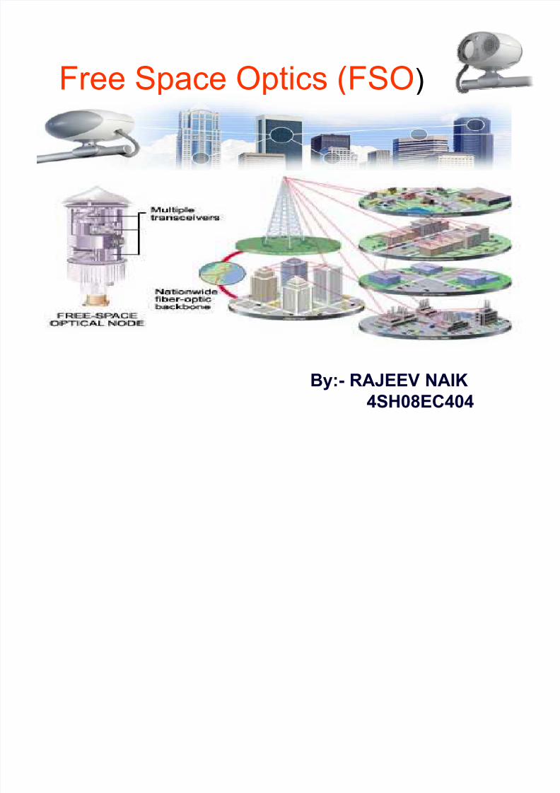
Free Space Optics (FSO)
By:- RAJEEV NAIK
4SH08EC404
8/7/2019 (fso)1 (2)
http://slidepdf.com/reader/full/fso1-2 2/31
8/7/2019 (fso)1 (2)
http://slidepdf.com/reader/full/fso1-2 3/31
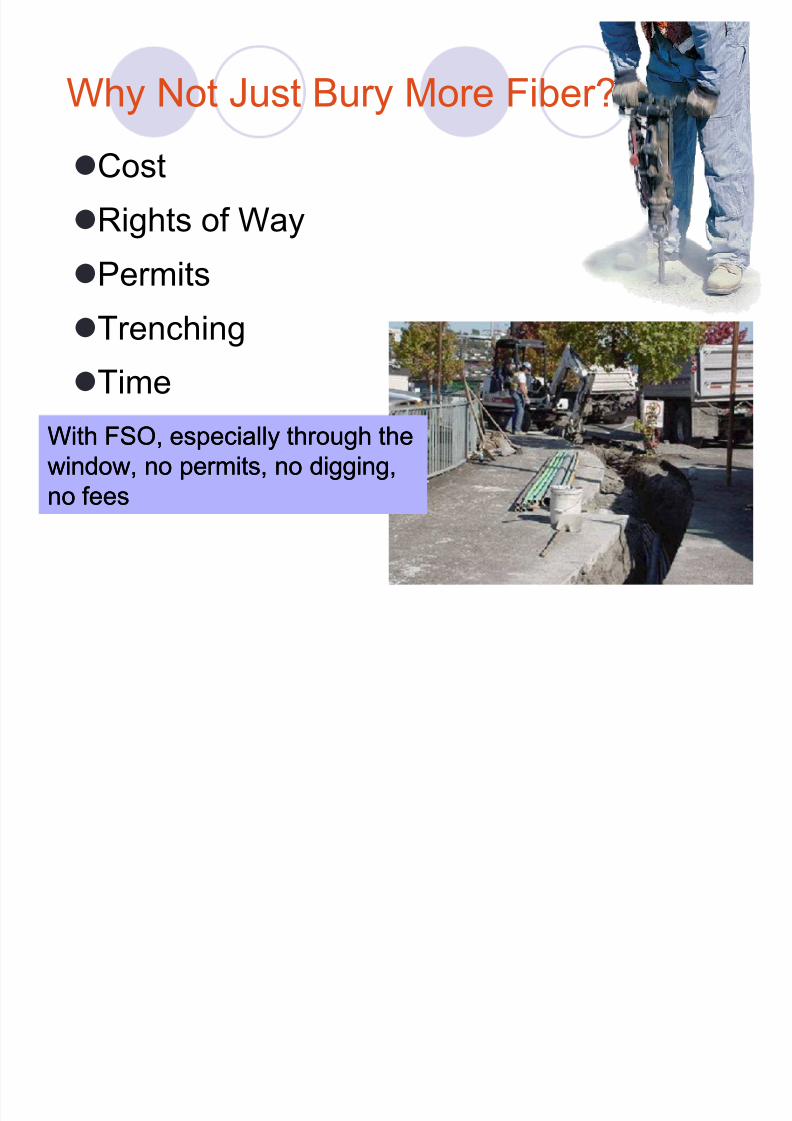
Why Not Just Bury More Fiber?
Cost
Rights of Way
PermitsTrenching
Time
With FSO, especially through theWith FSO, especially through thewindow, no permits, no digging,window, no permits, no digging,no feesno fees
8/7/2019 (fso)1 (2)
http://slidepdf.com/reader/full/fso1-2 4/31
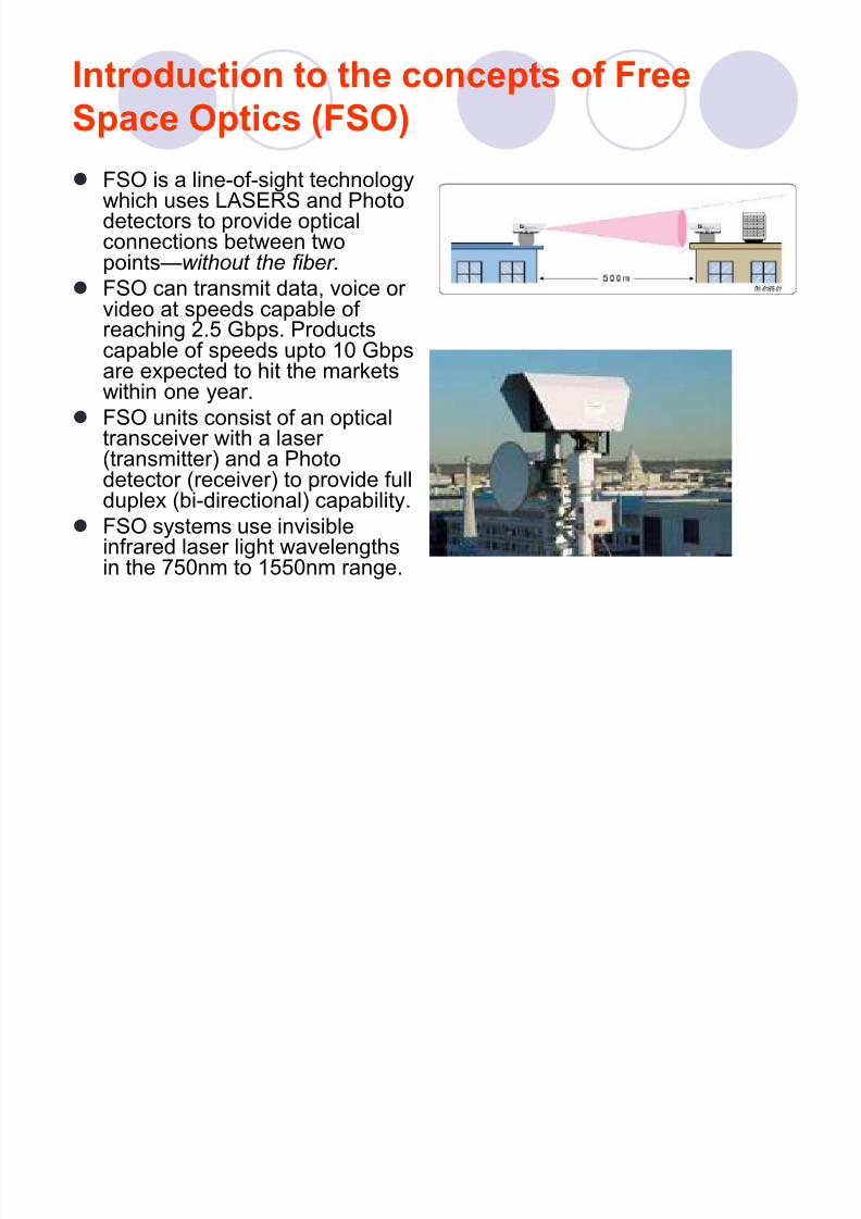
Introduction to the concepts of Free
Space Optics (FSO)
FSO is a line-of-sight technologywhich uses LASERS and Photodetectors to provide opticalconnections between twopoints²without the fiber.
FSO can transmit data, voice or video at speeds capable of reaching 2.5 Gbps. Productscapable of speeds upto 10 Gbpsare expected to hit the marketswithin one year.
FSO units consist of an opticaltransceiver with a laser (transmitter) and a Photodetector (receiver) to provide fullduplex (bi-directional) capability.
FSO systems use invisibleinfrared laser light wavelengthsin the 750nm to 1550nm range.
8/7/2019 (fso)1 (2)
http://slidepdf.com/reader/full/fso1-2 5/31
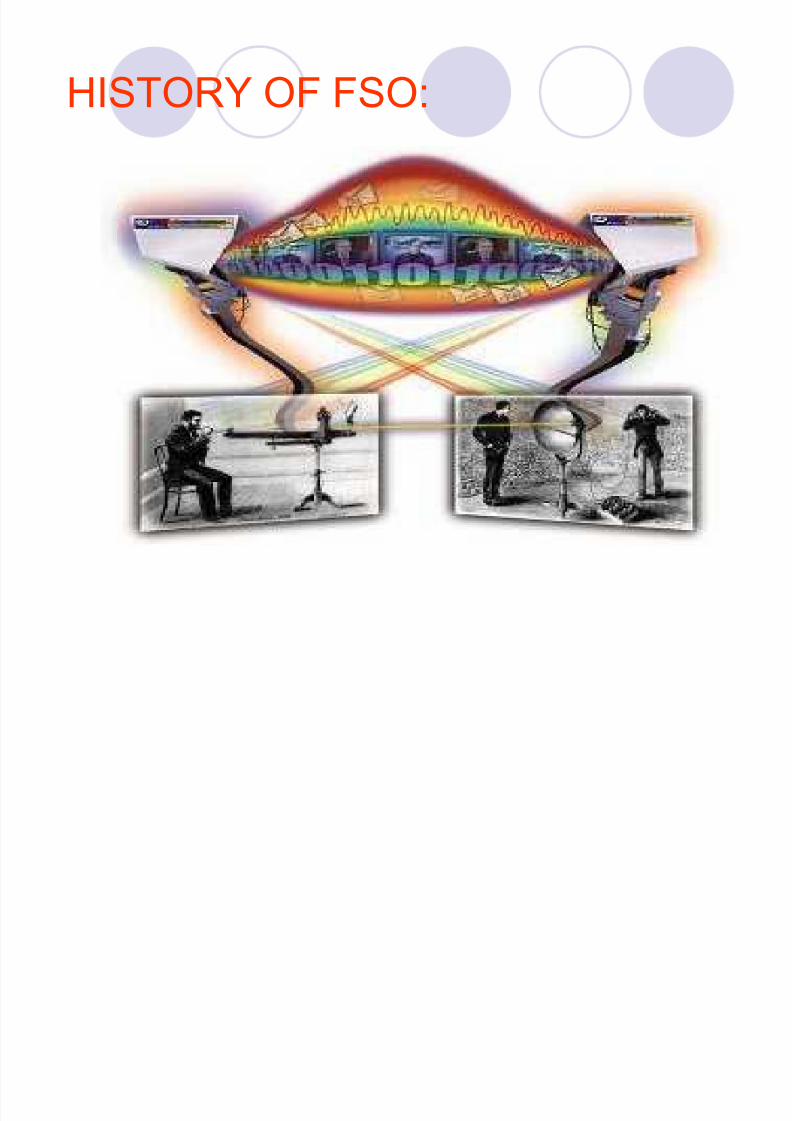
HISTORY OF FSO:
8/7/2019 (fso)1 (2)
http://slidepdf.com/reader/full/fso1-2 6/31
HISTORY OF FREE SPACE OPTICS(FSO)
Free space optics was first demonstrated by Alexander Graham Bellin late nineteenth century.
Bell's experiment converted voice sounds into telephone signals.
Late 1950¶s~early 1960's, several scientists theorized anddeveloped laser.
In the early 1980's U.S military and NASA made research on FSOfor inter-satellite communication proposes.
Germany, France and Japan made significantadvancements in free space optics for satellitecommunications since 1985 for private sector.
8/7/2019 (fso)1 (2)
http://slidepdf.com/reader/full/fso1-2 7/31
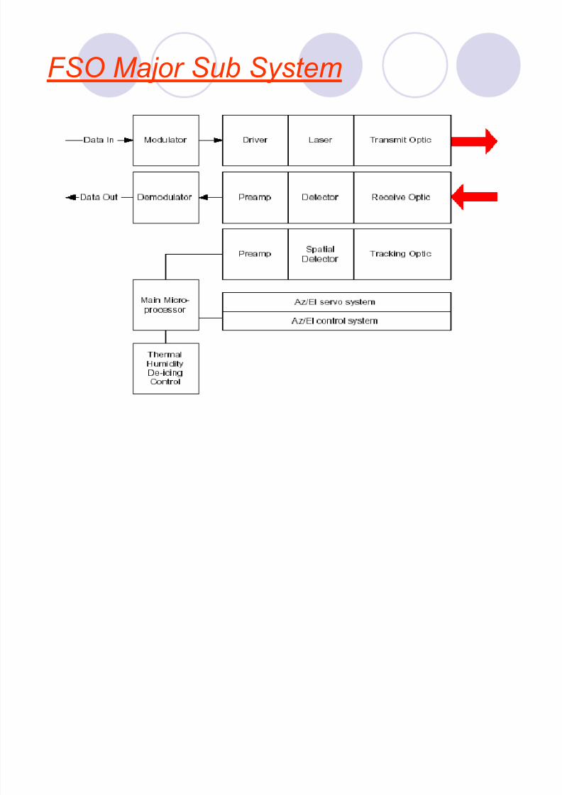
FSO Major S ub System
8/7/2019 (fso)1 (2)
http://slidepdf.com/reader/full/fso1-2 8/31
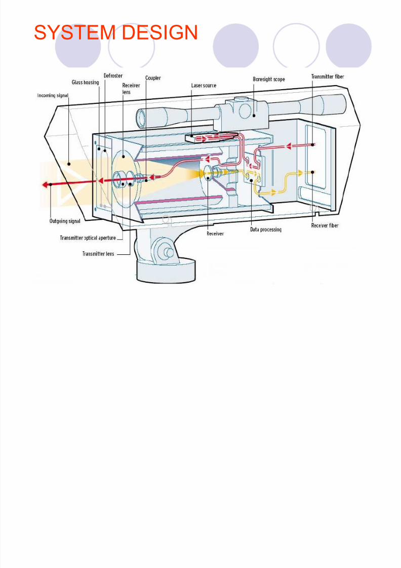
SYSTEM DESIGN
Based on connectivity between wireless units,each consisting of an transceiver.
Each unit uses
Optical sourceLens (transmitter and receiver)Optical receiver Transmitter fiber Receiver fiber
Photon detector receiver.Usually FSO uses laser,communication over
short distance will be done using LEDs.
8/7/2019 (fso)1 (2)
http://slidepdf.com/reader/full/fso1-2 9/31
SYSTEM DESIGN
8/7/2019 (fso)1 (2)
http://slidepdf.com/reader/full/fso1-2 10/31
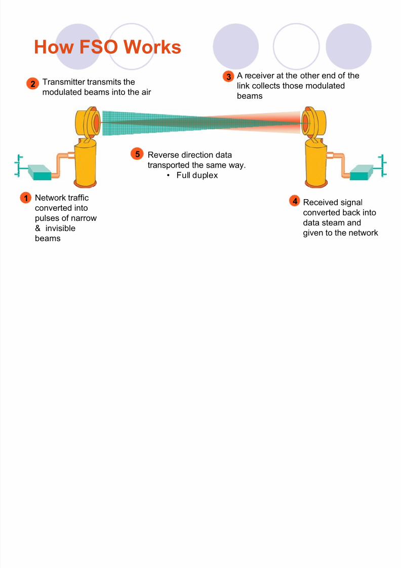
How FSO Works
1 Network traffic
converted intopulses of narrow& invisiblebeams
2 Transmitter transmits themodulated beams into the air
5 Reverse direction datatransported the same way.
� Full duplex
3 A receiver at the other end of thelink collects those modulatedbeams
4 Received signal
converted back intodata steam andgiven to the network
8/7/2019 (fso)1 (2)
http://slidepdf.com/reader/full/fso1-2 11/31
WAVELENGTHS USED
Depending on their robust property againstatmospheric absorption and possibility of their implementation
780nm-850nm
1529nm-1600nm
10,000nm(researches are going on)
8/7/2019 (fso)1 (2)
http://slidepdf.com/reader/full/fso1-2 12/31
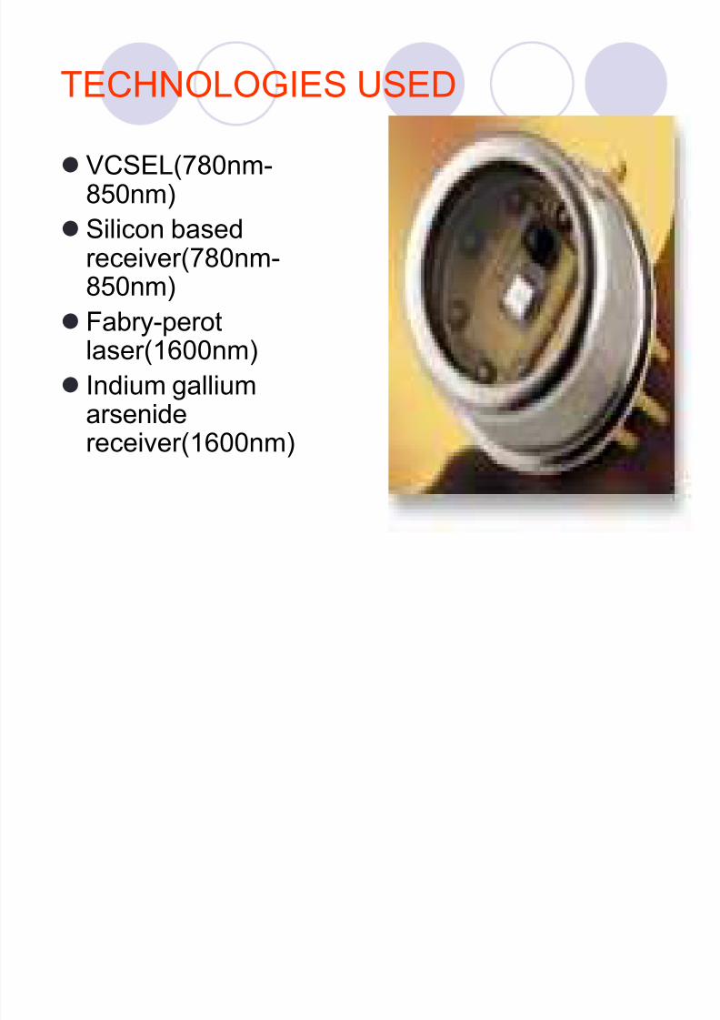
TECHNOLOGIES USED
VCSEL(780nm-850nm)
Silicon based
receiver(780nm-850nm)
Fabry-perotlaser(1600nm)
Indium galliumarsenidereceiver(1600nm)
8/7/2019 (fso)1 (2)
http://slidepdf.com/reader/full/fso1-2 13/31
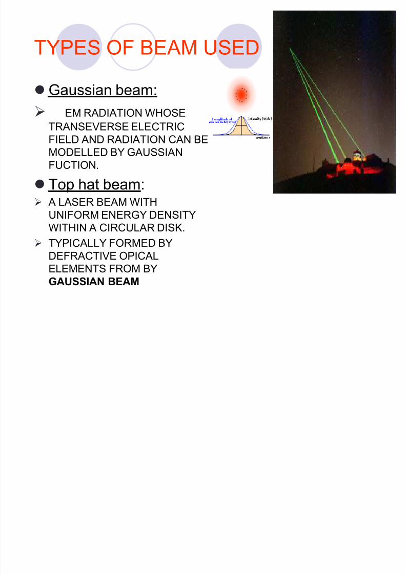
TYPES OF BEAM USED
Gaussian beam:
EM RADIATION WHOSE
TRANSEVERSE ELECTRIC
FIELD AND RADIATION CAN BEMODELLED BY GAUSSIANFUCTION.
Top hat beam: A LASER BEAM WITH
UNIFORM ENERGY DENSITYWITHIN A CIRCULAR DISK.
TYPICALLY FORMED BYDEFRACTIVE OPICALELEMENTS FROM BY
GAUSSIAN BEAM
8/7/2019 (fso)1 (2)
http://slidepdf.com/reader/full/fso1-2 14/31
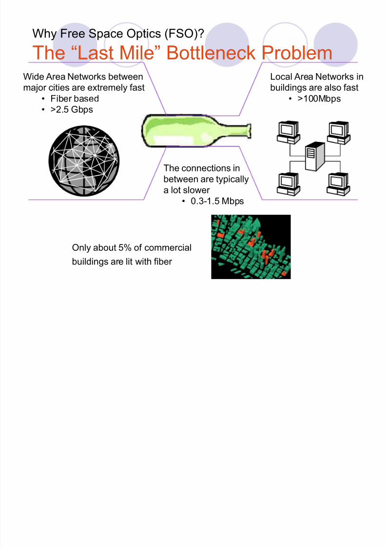
Why Free Space Optics (FSO)?
The ³Last Mile´ Bottleneck Problem
Only about 5% of commercial
buildings are lit with fiber
Wide Area Networks betweenmajor cities are extremely fast
� Fiber based� >2.5 Gbps
Local Area Networks inbuildings are also fast
� >100Mbps
The connections inbetween are typicallya lot slower
� 0.3-1.5 Mbps
8/7/2019 (fso)1 (2)
http://slidepdf.com/reader/full/fso1-2 15/31
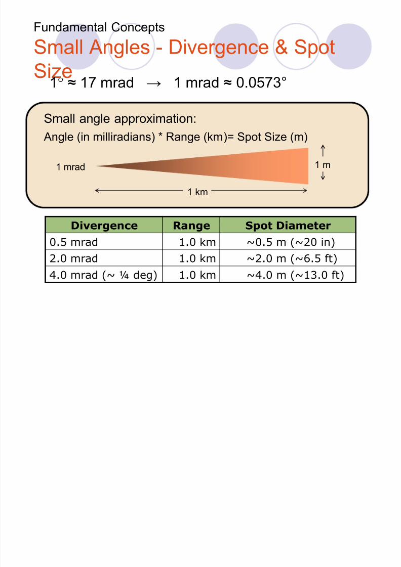
Fundamental Concepts
Small Angles - Divergence & Spot
Size
1 mrad
1 km
1 m
Small angle approximation:
Angle (in milliradians) * Range (km)= Spot Size (m)
Divergence Range Spot Diameter
0.5 mrad 1.0 km ~0.5 m (~20 in)
2.0 mrad 1.0 km ~2.0 m (~6.5 ft)
4.0 mrad (~ ¼ deg) 1.0 km ~4.0 m (~13.0 ft)
1° § 17 mrad 1 mrad § 0.0573°
8/7/2019 (fso)1 (2)
http://slidepdf.com/reader/full/fso1-2 16/31
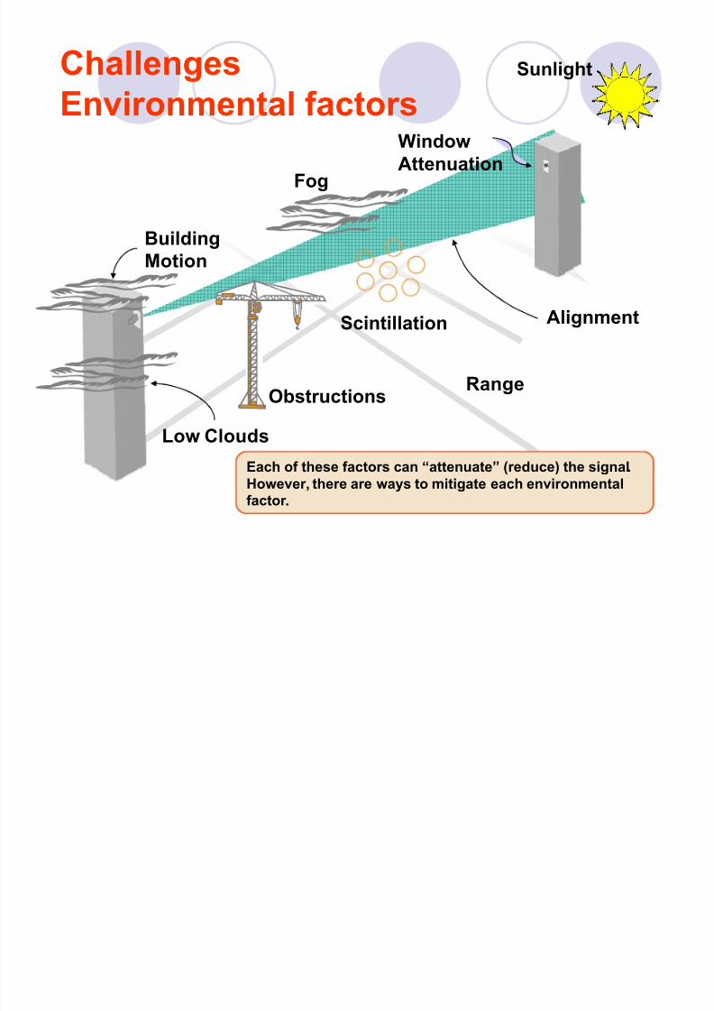
Challenges
Environmental factors
Sunlight
Building
Motion
Alignment
Window
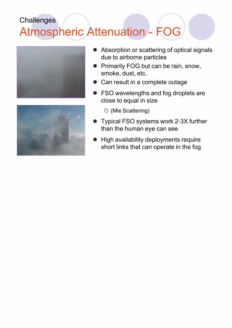
AttenuationFog
Each of these factors can ³attenuate´ (reduce) the signal.
However, there are ways to mitigate each environmental
factor .
Scintillation
RangeObstructions
Low Clouds
8/7/2019 (fso)1 (2)
http://slidepdf.com/reader/full/fso1-2 17/31
8/7/2019 (fso)1 (2)
http://slidepdf.com/reader/full/fso1-2 18/31
Challenges
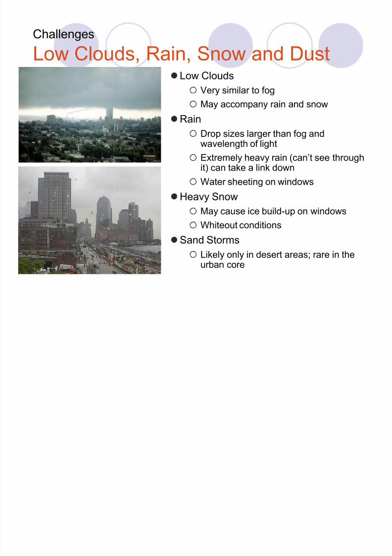
Low Clouds, Rain, Snow and DustLow Clouds
Very similar to fog
May accompany rain and snow
Rain
Drop sizes larger than fog andwavelength of light
Extremely heavy rain (can¶t see throughit) can take a link down
Water sheeting on windows
Heavy Snow
May cause ice build-up on windows
Whiteout conditions
Sand Storms
Likely only in desert areas; rare in theurban core
8/7/2019 (fso)1 (2)
http://slidepdf.com/reader/full/fso1-2 19/31
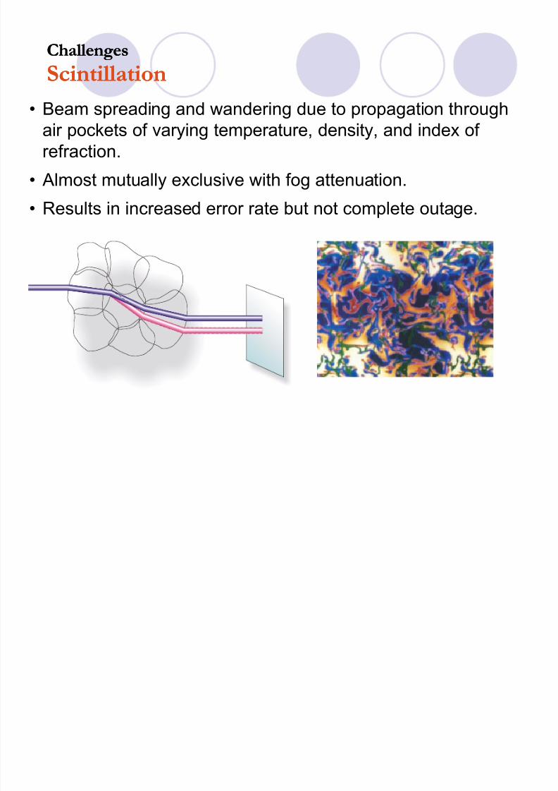
� Beam spreading and wandering due to propagation throughair pockets of varying temperature, density, and index of refraction.
� Almost mutually exclusive with fog attenuation.
� Results in increased error rate but not complete outage.
Challenges
ScintillationChallenges
Scintillation
8/7/2019 (fso)1 (2)
http://slidepdf.com/reader/full/fso1-2 20/31
Challenges
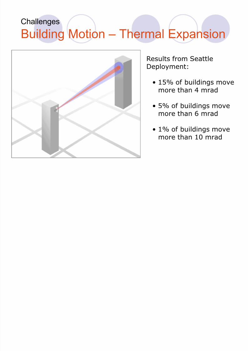
Building Motion ± Thermal Expansion
R esults from SeattleDeployment:
� 15% of buildings movemore than 4 mrad
� 5% of buildings movemore than 6 mrad
� 1% of buildings movemore than 10 mrad
8/7/2019 (fso)1 (2)
http://slidepdf.com/reader/full/fso1-2 21/31
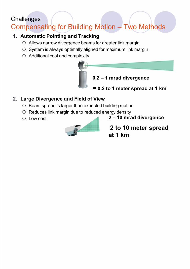
1. Automatic Pointing and Tracking
Allows narrow divergence beams for greater link margin
System is always optimally aligned for maximum link margin
Additional cost and complexity
2.
Large Divergence and Field of View Beam spread is larger than expected building motion
Reduces link margin due to reduced energy density
Low cost
Challenges
Compensating for Building Motion ± Two Methods
0.2 ± 1 mrad divergence
= 0.2 to 1 meter spread at 1 km
2 ± 10 mrad divergence
2 to 10 meter spread
at 1 km
8/7/2019 (fso)1 (2)
http://slidepdf.com/reader/full/fso1-2 22/31
FSO SECURITY
FSO is more secure than other wireless-basedtransmission technologies.
FSO laser beams cannot be detected with spectrum
analyzers or RF meters. It requires a matching Free Space Optics FSO
transceiver.
beams generated by FSO systems are narrow
and invisible.Data transmitted over an encrypted connection.
8/7/2019 (fso)1 (2)
http://slidepdf.com/reader/full/fso1-2 23/31
APPLICATIONS
TOP 5 APPLICATIONS
Telecommunication Networks
Computer Networks (LAN-to-LAN)
Broadband Internet Access
Disaster Recovery
Temporary Deployment
TYPICAL APPLICATIONS
Short distance LAN extension
Internet/intranet provision
Traffic Grooming in Cell Networks
Airports, Railways

8/7/2019 (fso)1 (2)
http://slidepdf.com/reader/full/fso1-2 24/31
...(CONTD)
ENTERPRISE APPLICATIONS
Entreprise Connectivity
Health Care
Engineering & design
Video services Security
8/7/2019 (fso)1 (2)
http://slidepdf.com/reader/full/fso1-2 25/31
Limitations
� Unreliable Bandwidth availability : Variations in weather conditions affect available bandwidth
� Requires Line of Sight link
� Limited Range
� Need sophisticated mechanism for alignment of thetransmitter and receiver
� Even slight mechanical disturbances may lead to loss of alignment, and may result in complete link break-down
8/7/2019 (fso)1 (2)
http://slidepdf.com/reader/full/fso1-2 26/31
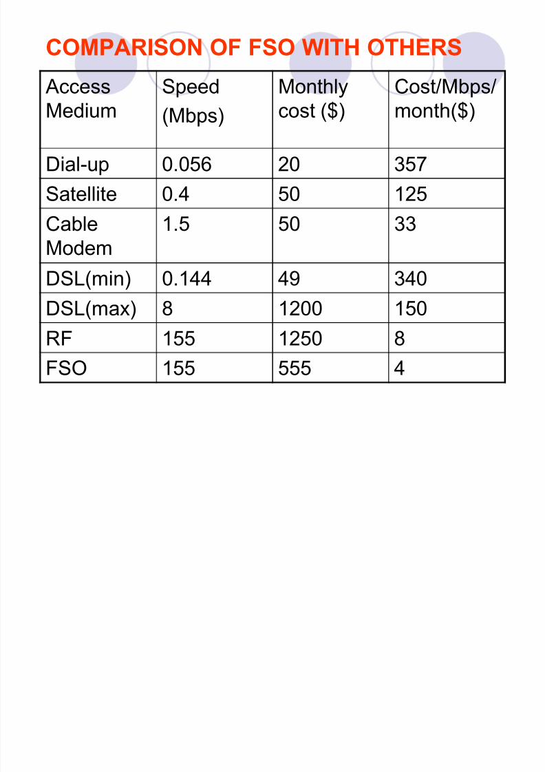
COMPARISON OF FSO WITH OTHERS
AccessMedium
Speed
(Mbps)
Monthlycost ($)
Cost/Mbps/month($)
Dial-up 0.056 20 357
Satellite 0.4 50 125CableModem
1.5 50 33
DSL(min) 0.144 49 340DSL(max) 8 1200 150
RF 155 1250 8
FSO 155 555 4
8/7/2019 (fso)1 (2)
http://slidepdf.com/reader/full/fso1-2 27/31
WHY FSO ?
DEMAND OF MORE BANDWIDTH.
OFFER LOWEST COST.
REQUIRES LESS INSTALLATION TIME.
FSO BRINGS NEW POSSIBLE TECHNOLOGY THAT
MAY NOT BE ABLE TO BE FULFILLED BY ANOTHERACCESS TECHNOLOGY
8/7/2019 (fso)1 (2)
http://slidepdf.com/reader/full/fso1-2 28/31
FUTURE OF FSO
FSO technology became popular as it was used toenable the Wall Street Stock Exchange back tobusiness after the 9/11 tragedy in less than 48 hours.
Manufacturers of FSO optical products areLightPointer, AirFiber, and Fsona Communications.
It is an alternative to fiber optics technology.
In future FSO will be used everywhere.
like cellular base station, Wi-Fi hotspots, disaster recovery etc.
8/7/2019 (fso)1 (2)
http://slidepdf.com/reader/full/fso1-2 29/31
CONCLUSION
Free-space optics technology is a goodalternative, especially compare to fiber optics.
In the future, FSO may be one of the mostimportant access technologies due to itsadvantages.
It will capture big market in the future.

8/7/2019 (fso)1 (2)
http://slidepdf.com/reader/full/fso1-2 30/31

8/7/2019 (fso)1 (2)
http://slidepdf.com/reader/full/fso1-2 31/31