Embed Size (px)
Citation preview
MAINTENANCE
FRICK® QUANTUM™ LXCOMPRESSOR
CONTROL PANELVersion 7.0x
Form 090.020-M (SEP 2011) MAINTENANCE
File: SERVICE MANUAL - Section 90Replaces: 090.020-M (JUNE 2011)Dist: 3, 3a, 3b, 3c
QUANTUM™ LX COMPRESSOR CONTROL PANELMAINTENANCE
090.020-M (SEP 11)Page 2
TABLE OF CONTENTS
SECTION 1INTRODUCTION TO THE QUANTUM™ CONTROL SYSTEM......................................................................................8
INTRODUCTION..........................................................................................................................................................8Quantum™ Controller..........................................................................................................................................8Power Supply.......................................................................................................................................................8Digital Input / Output Boards................................................................................................................................8Analog Input / Output Boards...............................................................................................................................8Operator Interface...............................................................................................................................................8
THE CONTROL PANEL ENCLOSURE..............................................................................................................................8GENERAL INFORMATION............................................................................................................................................8WHAT TO DO BEFORE CALLING THE FACTORY...........................................................................................................9
SECTION 2Q5
INTRODUCTION.........................................................................................................................................................12FEATURES.................................................................................................................................................................12WHAT SHOULD OCCUR WHEN APPLYING POWER....................................................................................................12WHAT IF THE OPERATING STATUS SCREEN IS NOT SHOWN.....................................................................................12BATTERY FUNCTION AND REPLACEMENT..................................................................................................................13Q5 INTERFACE BOARD..............................................................................................................................................13Q5 BOARD PICTORIAL...............................................................................................................................................14Q5 JUMPERS, LED’S AND CONNECTORS...................................................................................................................15
Jumper Table.....................................................................................................................................................15LED Defi nition Table....................................................................................................................................15Connector Pinout Table................................................................................................................................15
Q5 INTERFACE BOARD PICTORIAL.............................................................................................................................16COMM 1 Jumpers..............................................................................................................................................16COMM 2 Jumpers..............................................................................................................................................16
Q5 INTERCONNECTIONS............................................................................................................................................17POWER SUPPLY........................................................................................................................................................18
DESCRIPTION ....................................................................................................................................................18POWER DISTRIBUTION......................................................................................................................................18MEASURING VOLTAGES.....................................................................................................................................18ADJUSTMENT....................................................................................................................................................19
+5VDC........................................................................................................................................................19+12VDC......................................................................................................................................................19+24VDC......................................................................................................................................................19
POWER SUPPLY REPLACEMENT..........................................................................................................................19Q5 FLOW DIAGRAM..................................................................................................................................................20Q5 RDB / RWB II / RWF / RXF (58 - 101) CONTROL CENTER ASSEMBLY....................................................................21Q5 I/O & D.C. POWER HARNESS...............................................................................................................................25Q5 A. C. POWER HARNESS.......................................................................................................................................26
Q5 COMPRESSOR REPLACEMENT PARTS..................................................................................................................28
SECTION 3QUANTUM 4
INTRODUCTION........................................................................................................................................................32WHAT SHOULD OCCUR WHEN APPLYING POWER....................................................................................................32WHAT IF THE OPERATING STATUS SCREEN IS NOT SHOWN.....................................................................................32BATTERY FUNCTION AND REPLACEMENT..................................................................................................................33QUANTUM 4 BOARD PICTORIAL................................................................................................................................34QUANTUM 4 BOARD SETTINGS.................................................................................................................................35
Processor Board Jumpers...................................................................................................................................35Communications Board Jumpers.........................................................................................................................35
Com-1 (TB1)...............................................................................................................................................35Com-2 (TB2 - TB3).....................................................................................................................................35
POWER SUPPLY........................................................................................................................................................36DESCRIPTION ....................................................................................................................................................36MEASURING VOLTAGES......................................................................................................................................36FUSE REPLACEMENT..........................................................................................................................................37
QUANTUM™ LX COMPRESSOR CONTROL PANELMAINTENANCE
090.020-M (SEP 11)Page 3
ADJUSTMENT.....................................................................................................................................................38POWER SUPPLY REPLACEMENT..........................................................................................................................39+5 DC VOLTAGE MEASUREMENT LOCATION.......................................................................................................40DC POWER SUPPLY PIN ASSIGNMENTS.............................................................................................................40
QUANTUM 4 FLOW DIAGRAM36 & 48 INCH PANELS.........................................................................................................................................4022 & 28 INCH PANELS.........................................................................................................................................41
QUANTUM 4 RDB / RWB II / RWF / RXF (58 - 101) CONTROL CENTER ASSEMBLY....................................................42QUANTUM 4 I/O & D.C. POWER HARNESS (36 AND 48 INCH PANELS ).....................................................................46QUANTUM 4 I/O & D.C. POWER HARNESS (22 AND 28 INCH PANELS)......................................................................47QUANTUM 4 COMPRESSOR REPLACEMENT PARTS..................................................................................................48
SECTION 4DIGITAL BOARD....................................................................................................................................................52
INFORMATION..........................................................................................................................................................52DIGITAL BOARD DESCRIPTION..................................................................................................................................52COMMUNICATIONS LED'S..........................................................................................................................................52CONNECTIONS TO THE QUANTUM 4.........................................................................................................................52LOGIC VOLTAGE (POWER) LED..................................................................................................................................53ACTIVE LED...............................................................................................................................................................53DIGITAL INPUTS........................................................................................................................................................53DIGITAL OUTPUTS....................................................................................................................................................54CHECKING THE DIGITAL INPUTS AND OUTPUTS........................................................................................................54FUSE TESTING AND REPLACEMENT...........................................................................................................................54INPUT AND OUTPUT MODULE TESTING AND REPLACEMENT....................................................................................54TROUBLESHOOTING AN OUTPUT...............................................................................................................................54TROUBLESHOOTING AN INPUT..................................................................................................................................55REPLACING A DEFECTIVE DIGITAL BOARD.................................................................................................................55DIGITAL I/O BOARD #1 PICTORIAL.............................................................................................................................56DIGITAL I/O BOARD #2 PICTORIAL.............................................................................................................................57DIGITAL BOARD SETTINGS.......................................................................................................................................58
COMMUNICATIONS SETTINGS............................................................................................................................58DIPSWITCH SETTINGS.......................................................................................................................................58
SECTION 5ANALOG BOARD..................................................................................................................................................60
OVERVIEW................................................................................................................................................................60ANALOG BOARD VERSIONS......................................................................................................................................60ANALOG BOARD DESCRIPTION.................................................................................................................................60COMMUNICATIONS LED'S..........................................................................................................................................60CONNECTIONS TO THE QUANTUM™.........................................................................................................................61LOGIC VOLTAGE (POWER) LED’S................................................................................................................................61ACTIVE LED...............................................................................................................................................................61ANALOG INPUTS.......................................................................................................................................................61ANALOG BOARD INPUT CONFIGURATION TABLE.......................................................................................................62ANALOG OUTPUTS...................................................................................................................................................63TROUBLESHOOTING THE ANALOG INPUTS AND OUTPUTS.......................................................................................63REPLACING A DEFECTIVE ANALOG BOARD...............................................................................................................63PHD VIBRATION ANALYSIS.......................................................................................................................................64CURRENT TRANSFORMER (MOTOR AMPS)...............................................................................................................65ANALOG BOARD #1 PICTORIAL.................................................................................................................................66ANALOG BOARD #2 PICTORIAL.................................................................................................................................67ANALOG BOARD SETTINGS......................................................................................................................................68
Communications................................................................................................................................................68Current Transformer (CT)...........................................................................................................................68Vibration....................................................................................................................................................68Dipswitch Settings (Used To Set The Board Address).................................................................................68Analog Board Comparison Chart.................................................................................................................68
SECTION 6OPERATOR INTERFACE.........................................................................................................................................70
DESCRIPTION............................................................................................................................................................70
QUANTUM™ LX COMPRESSOR CONTROL PANELMAINTENANCE
090.020-M (SEP 11)Page 4
Display Assembly...............................................................................................................................................70Identifying The Type of Display..........................................................................................................................70Display Replacement.........................................................................................................................................70
QUANTUM 4 SPECIFIC INFORMATION........................................................................................................................71Q5 SPECIFIC INFORMATION......................................................................................................................................71KEYPAD.....................................................................................................................................................................72
Keypad Troubleshooting....................................................................................................................................72Keypad Replacement.........................................................................................................................................73
SECTION 7SERVICE SCREENS................................................................................................................................................76
Digital Board Inputs and Outputs...............................................................................................................................76Analog Board Inputs and Outputs..............................................................................................................................76Motor Bump..............................................................................................................................................................77Software Maintenance..............................................................................................................................................78
SYSTEM STATUSMaintenance.............................................................................................................................................................82
CONFIGURATIONCommunications.......................................................................................................................................................83
MISCELLANEOUS SCREENSAbout.......................................................................................................................................................................84
SECTION 8TROUBLESHOOTING
TROUBLESHOOTING A PROBLEM THAT APPEARS UNEXPLAINABLE.........................................................................85TROUBLESHOOTING CHART FOR FRICK® QUANTUM™ LX CONTROL PANEL...........................................................87
SECTION 9SETPOINT DATA SHEETS.......................................................................................................................................91
OPERATING VALUESUsed Defi ned.....................................................................................................................................................91
MODE SETUP............................................................................................................................................................92SYSTEM STATUS
Trending Setup..................................................................................................................................................93Maintenance......................................................................................................................................................94
SETPOINTSCapacity Control Setpoints
Mode 1.......................................................................................................................................................95Mode 2.......................................................................................................................................................96Mode 3.......................................................................................................................................................97Mode 4.......................................................................................................................................................98
SequencingSystem 1 Setup..........................................................................................................................................99System 2 Setup.........................................................................................................................................100System 3 Setup.........................................................................................................................................101Sequencing Control...................................................................................................................................102
Compressor Safeties Setpoints.........................................................................................................................103Package Safeties.............................................................................................................................................104Motor (Engine/DBS/Motor/Turbine/Vyper)........................................................................................................105Capacity Position.............................................................................................................................................107Condenser Digital Control.................................................................................................................................107Condenser Analog Control................................................................................................................................107Miscellaneous..................................................................................................................................................108Scheduling.......................................................................................................................................................108PHD Monitoring...............................................................................................................................................109PID Setup
Page 1.......................................................................................................................................................110Page 2.......................................................................................................................................................111
Superheat Control Setup...................................................................................................................................112Discharge Butterfl y Setup..................................................................................................................................113Auxiliary Analog Input Safeties
Page 1.......................................................................................................................................................114Page 2.......................................................................................................................................................115
QUANTUM™ LX COMPRESSOR CONTROL PANELMAINTENANCE
090.020-M (SEP 11)Page 5
Auxiliary Digital Input Confi guration..................................................................................................................116Auxiliary Digital Output Confi guration...............................................................................................................117Timed Digital Output Confi guration..................................................................................................................119Panel................................................................................................................................................................119
CALIBRATIONPressure...........................................................................................................................................................120Temperature.....................................................................................................................................................122Capacity/Volume..............................................................................................................................................123Motor/Miscellaneous........................................................................................................................................123PhD Monitoring................................................................................................................................................125Analog Outputs (Retransmitting Outputs).........................................................................................................127Analog Outputs (VFD / Condenser Outputs)......................................................................................................128Analog Output Calibration.................................................................................................................................128Auxiliaries Analogs (Page 1).............................................................................................................................129Auxiliaries (Page 2)..........................................................................................................................................130
CONFIGURATIONCompressor......................................................................................................................................................131Communications..............................................................................................................................................132Ethernet...........................................................................................................................................................132Digital I/O.........................................................................................................................................................133
SECURITY................................................................................................................................................................135SESSION..................................................................................................................................................................135ABOUT.....................................................................................................................................................................135
SECTION 10QUANTUM™ LX DRAWINGS................................................................................................................................139
RXF (12-50) RETROFIT MOUNTING..........................................................................................................................140WIRING DIAGRAM – RWF & RWFII..........................................................................................................................141WIRING DIAGRAM – RWB II....................................................................................................................................145WIRING DIAGRAM – RXF (12-101)............................................................................................................................149WIRING DIAGRAM – RDB........................................................................................................................................153WIRING DIAGRAM PHD...........................................................................................................................................157WIRING DIAGRAM - DIGITAL I/O BOARD 2..............................................................................................................158WIRING DIAGRAM - ANALOG I/O BOARD 2............................................................................................................160ISOLATER REPEATER MODULE.................................................................................................................................162COMMUNICATIONS WIRING DIAGRAMS...................................................................................................................163TO CUSTOMER REMOTE COMPUTER/DCS...............................................................................................................163
RS-485 COMMUNICATIONS...............................................................................................................................163RS-422 COMMUNICATIONS..............................................................................................................................163
POINT-TO-POINT FIELD WIRING DIAGRAM..............................................................................................................164
SECTION 11TABLES
PRESSURE TRANSDUCER CONVERSION DATA........................................................................................................165COMPRESSOR MODEL DIFFERENCES.......................................................................................................................165COMPRESSOR VOLUME RATIO AND CAPACITY INFORMATION..............................................................................166
THE FOLLOWING PUBLICATIONS ARE AVAILABLE FROM THE JOHNSON CONTROLS® WEBSITE jci.com
090.022-O Frick® Quantum™ LX Control Panel Operation – Service090.020-CS Frick® Quantum™ LX Control Panel Communications Setup (setup and wiring for data communication using
available protocols)090.020-M Frick® Quantum™ LX Control Panel Maintenance (repair and troubleshooting)

QUANTUM™ LX COMPRESSOR CONTROL PANELMAINTENANCE
090.020-M (SEP 11)Page 6
NOTES:
QUANTUM™ LX COMPRESSOR CONTROL PANELMAINTENANCE
090.020-M (SEP 11)Page 7
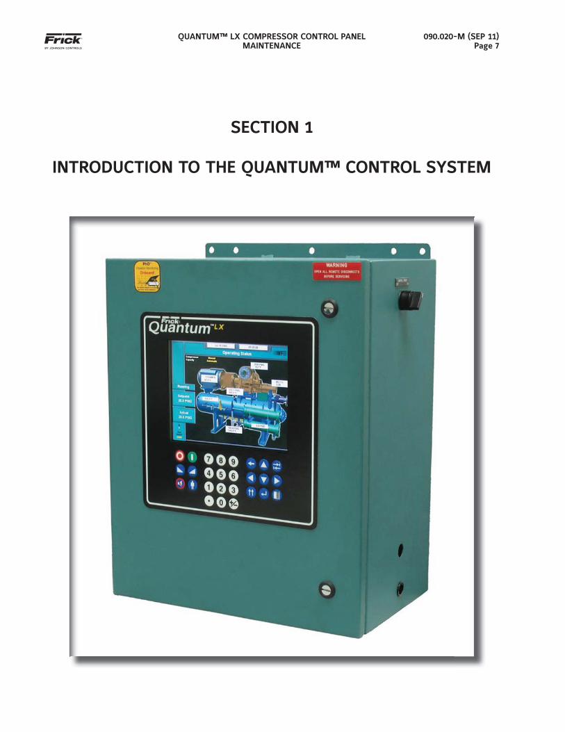
SECTION 1
INTRODUCTION TO THE QUANTUM™ CONTROL SYSTEM
QUANTUM™ LX COMPRESSOR CONTROL PANELMAINTENANCE
090.020-M (SEP 11)Page 8
INTRODUCTION TO THE QUANTUM™ CONTROL SYSTEM
INTRODUCTION
The Quantum™ LX panel differs from previous Quan-tum™ panels primarily in the software operating sys-tem. The hardware portion (with the exception of the new international style keypad and cable) remains the same. The Frick® Quantum™ LX control system con-sists of fi ve major areas:
• Quantum™ Controller - The brains of the system. Currently, there are two versions of Quantum™ board in production, the Quan-tum 4 board and the Q5 board. Both of these boards are discussed in greater detail later in this manual.
The combination of the hardware (Quan-tum™ board) and the software program that runs on it creates what we call the Quan-tum™ LX system. The Quantum™ board communicates with all of the Digital and Analog boards. This communication al-lows the Quantum™ to read the status of all the I/O boards, and display the data on the interface screen. The Quantum™ acts on this data, and provides the necessary control information to the I/O boards to provide the appropriate control of all input and output signals, based upon the con-fi guration of installed features and options of the compressor package. Operator inter-action is provided through the keypad, as well as informational status to the display. Interaction to the outside world is provided through industry-standard communications protocols. Additional information about the Quantum™ can be found under the QUAN-TUM™ CONTROLLER sections found later in this manual.
• Power Supply - Provides the necessary op-erating voltages for the proper operation of all control components. Additional informa-tion about the power supply can be found under the POWER SUPPLY sections found later in this manual.
• Digital Input / Output Boards - Digital (on/off) signals are sent and received by these boards. The output signals are used for en-ergizing solenoids, valves, contactors, re-lays, etc., and the input signals are used to sense the condition of switches, relay con-tacts, auxiliary contacts, etc. This board runs an independent software program from the Quantum™ to control devices, and commu-nicates the status of all devices back to the Quantum™. Additional information about the Digital Boards can be found under the DIGITAL BOARD section found later in this manual.
• Analog Input / Output Boards - Analog (variable) signals are sent and received by these boards. The output signals are used for controlling VFDs, modulated valves, etc., and the input signals are used to read the values being sent from pressure transduc-ers, temperature sensors, etc. This board runs an independent software program from the Quantum™ to control devices, and communicates the status of all devices back to the Quantum™. The Analog board has 24 analog inputs, and 8 analog outputs. Addi-tional information about the Analog board can be found under the ANALOG BOARD section found later in this manual.
• Operator Interface - This section actu-ally consists of two major components; the Display and the Keypad. The Display is used to show the operator, via a graphical inter-face, the actual status of all compressor val-ues. Warnings and shutdowns (and history/trending), pressure and temperature values, digital I/O status, setpoints, etc. are viewed on this display. The Keypad is used by the operator to enter data to the Quantum™ controller such as setpoint values, calibra-tion data, etc. Additional information about the Display can be found under the DISPLAY section found later in this manual.
THE CONTROL PANEL ENCLOSURE
The Frick® Quantum™ LX control panel enclosure utilizes available space effi ciently and the small size allows it to be used on all of our compressor pack-ages. The panel is also equipped with the neces-sary posts and hardware to add options in the fi eld. They may also include a second analog and/or digital board, enclosure heater and air-circulating fan.
Dimensions of the standard panel are 18x22x10 inch-es (WxHxD) and weighs approximately 75 pounds with all options. Typically the panel will be mounted on the package, but it is also designed for easy wall mounting as well. Refer to the Control Center Assem-bly drawing 649D5151 for the layout for this standard enclosure.
The DC power/communications harness in this pan-el is color-coded. This will make wire identifi cation much easier. The coding is as follows:
• +5VDC - RED• +12VDC - YELLOW• -12VDC - PURPLE • Common/Ground - BLACK• +RX/TX - BLUE• -RX/TX - BLUE w/WHITE stripe

QUANTUM™ LX COMPRESSOR CONTROL PANELMAINTENANCE
090.020-M (SEP 11)Page 9
GENERAL INFORMATION
The components within the control panel can be inadvertently damaged by static electricity or mis-handling. Only qualifi ed technicians should directly handle these components.
1. DO NOT attempt to make corrections to the power supply without shutting off the power to the control panel. Accidental shorts can irreparably damage the processor boards or the display screen.
2. DO NOT HANDLE the panel boards when their cables are disconnected without fi rst attaching a properly grounded wrist ground strap to prevent static electrical discharge from your body.
Most problems encountered with the microprocessor and control circuits will be the result of a wiring fault, a blown fuse, faulty I/O module or failure of a pe-ripheral control such as a solenoid coil or a pressure transducer. Faults in the computer, while possible, are unlikely. If a fault develops in the computer, the prob-ability is that all functions will cease and the display screen will go blank. The control system of the com-pressor consists of an AC (high voltage) side, which can be either 120 volts, or 230 volts, and a DC (low voltage) side. The AC side actuates solenoids, relays, alarms, and other electromechanical functions. The DC side operates the computer and its various sen-sors.
When working within the panel, the AC high volt-age side, which can be either nominal 120 VAC or nominal 230 VAC, CAN CAUSE INJURY OR DEATH.
To troubleshoot the low-voltage side of the control circuits, it is necessary to have the following tools:
1. Accurate digital multimeter (capable of reading to DC/AC, mA to the hundreds place)
2. Small wire stripper
3. Small screwdriver (with insulated shaft)4. Small snip nose pliers
5. Wrist Grounding strap 6. Static free grounded work surface
Note: Proper panel voltage refers to the AC (high volt-age) that has been supplied to the panel, which could be either nominal 120 VAC or nominal 230 VAC (Reference the Control Panel Power Specifi cations).
WHAT TO DO BEFORE CALLING THE FACTORY
Many times when a suspected Quantum™ problem is called in to the factory, not enough information is provided for the service personnel to assist in solving the problem. This is because the caller most likely is not aware of the type of information that would be useful to factory personnel in helping to identify and correct the problem. An example of this is the statement that the Quantum™ is not booting (the main processor board is not starting). Unfortunately, this description is usually vague and only means that there is nothing on the display. A blank screen could be the result of many different problems. The follow-ing is a list of possible reasons for no display:
• No power
• Loose or Faulty Display Cable or Inverter Cable
• Bad Display
• Bad Backlight Inverter
• Bad Backlight Fluorescent Tube
• Wrong Combination of Display, Cable, In-verter, or Software
• Faulty CPU Board
Before calling the factory for assistance, review the information on the following pages and try to dis-cover and resolve your Quantum™ LX problem. The actual cause of most problems is usually not with the Quantum™ board itself, but with something external. However, on the rare occasion that the problem has been identifi ed as being the Quantum™ board, use the following section as a guideline for replacing it.

QUANTUM™ LX COMPRESSOR CONTROL PANELMAINTENANCE
090.020-M (SEP 11)Page 10
NOTES:
QUANTUM™ LX COMPRESSOR CONTROL PANELMAINTENANCE
090.020-M (SEP 11)Page 11
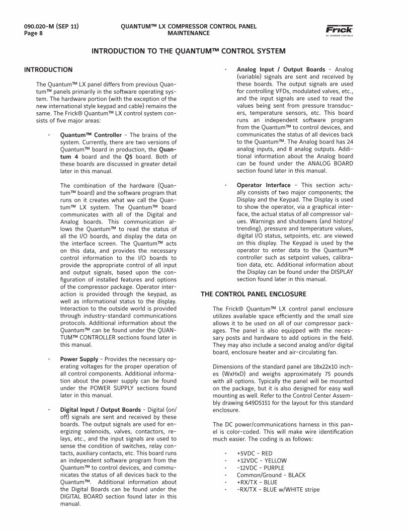
SECTION 2
Q5 CONTROLLER
QUANTUM™ LX COMPRESSOR CONTROL PANELMAINTENANCE
090.020-M (SEP 11)Page 12
Q5 CONTROLLER BOARD
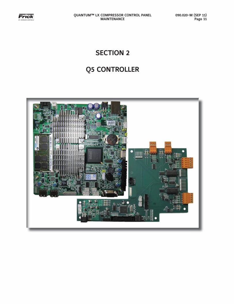
INTRODUCTION
Frick® Controls has released the latest version of the Quantum ™ LX microprocessor board. This brand will be referred to as the Q5. A photo of this board ap-pears here:
WHAT SHOULD OCCUR WHEN APPLYING POWER
When powering up, the following sequence of events are indicative of a properly working main processor board:
• The six LED’s in the lower left corner should turn on solid.
• The on-board “buzzer” should “beep” once.
• The display should show several DOS (text) style screens. A penguin image will appear in the upper left corner of the screen as the boot sequence progresses.
• Just before fully booting, a Loading bar will appear at the bottom of the screen, show-ing the percent of load that has completed.
• The Operating Status screen will appear.
After the Q5 has properly powered up, the following sequence of events is indicative of proper communi-cation to the analog and digital boards:
• The Analog and Digital I/O boards TX/RX lights should be blinking.
• Each I/O board should have the power LED lighted and the Active LED should be blink-ing.
• The fi rst thing that should be checked when troubleshooting the Quantum™ 5 board is its powering up sequence.
WHAT IF THE OPERATING STATUS SCREEN IS NOT SHOWN
If the Operating Status screen is not shown, check the following items:
1. If no LED’s are lit, then check AC and DC power. Refer to the Power Supply section.
2. Check if the lighting of the LED’s is occur-ring as described in the What Should Occur When Applying Powering section.
• If the powering up sequence continues to repeat without displaying the Op-erating Status screen, then there is a booting problem.
3. Check all plugged connectors for proper seating.
4. Check if an error message is displayed when booting.
• Be sure to write down any error mes-sages exactly as they appear, as well as the top line on the screen where the message appears.
5. Check that the software is OK:
• Is the correct software installed?
• Did you just install new software?
6. Check the display. If the Q5 board is booting but you have no display, check the following:
• Check the LCD backlight tube. Look very closely at the display to see if anything
FEATURES
The Q5 board includes the following features:
• 6 total USB ports (2 are dedicated, 4 are avail-able)
• 10/100/1000 Mbps Ethernet Connection• 2 RS-422 ports• 2 RS-485 ports• External Video monitor connection• LED indicators to verify proper operation of vari-
ous on board areas (power, communications, Ethernet connectivity, etc.)
• 2 GB RAM memory• Battery to maintain date and time
QUANTUM™ LX COMPRESSOR CONTROL PANELMAINTENANCE
090.020-M (SEP 11)Page 13
is visible in the dark screen. Using a beam type source of good lighting, such as a fl ashlight, look for any ghost type image. If it appears that there is some-thing on the screen but very dark, the problem may be with the LCD backlight tube. There is a sticker on the display mounting plate, that will have a part number that describes the type of dis-play. If there is no sticker, you must take the display apart to identify the display manufacturer.
• Verify that both the display cable and the inverter cable are fi rmly seated. It may be necessary to remove the video cable from the back of the LCD display and re-seat it to be sure it is connected properly. Note: This is a small connec-tor and caution should be observed so that it is not damaged due to excessive force.
• Refer to the Operator Interface section and check that the LCD, LCD cable, and software versions are matched correct-ly.
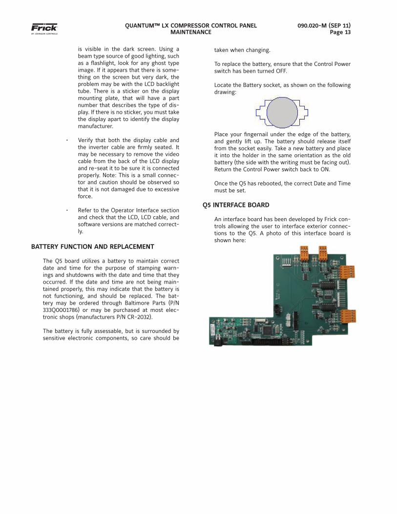
BATTERY FUNCTION AND REPLACEMENT
The Q5 board utilizes a battery to maintain correct date and time for the purpose of stamping warn-ings and shutdowns with the date and time that they occurred. If the date and time are not being main-tained properly, this may indicate that the battery is not functioning, and should be replaced. The bat-tery may be ordered through Baltimore Parts (P/N 333Q0001786) or may be purchased at most elec-tronic shops (manufacturers P/N CR-2032).
The battery is fully assessable, but is surrounded by sensitive electronic components, so care should be
taken when changing.
To replace the battery, ensure that the Control Power switch has been turned OFF.
Locate the Battery socket, as shown on the following drawing:
Place your fi ngernail under the edge of the battery, and gently lift up. The battery should release itself from the socket easily. Take a new battery and place it into the holder in the same orientation as the old battery (the side with the writing must be facing out). Return the Control Power switch back to ON.
Once the Q5 has rebooted, the correct Date and Time must be set.
Q5 INTERFACE BOARD
An interface board has been developed by Frick con-trols allowing the user to interface exterior connec-tions to the Q5. A photo of this interface board is shown here:
QUANTUM™ LX COMPRESSOR CONTROL PANELMAINTENANCE
090.020-M (SEP 11)Page 14
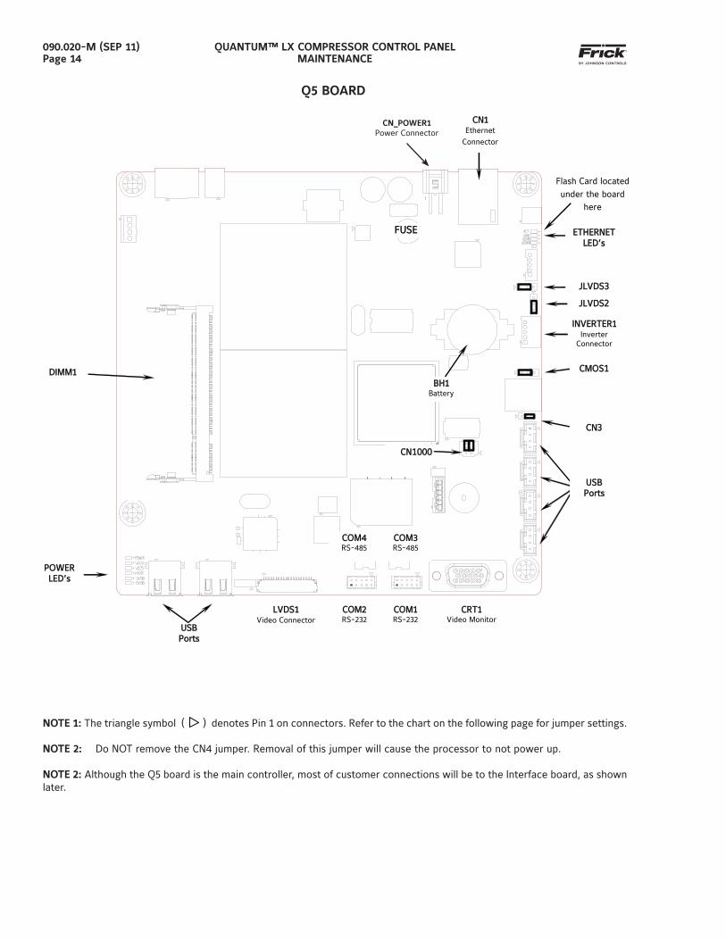
Q5 BOARD
NOTE 1: The triangle symbol ( ) denotes Pin 1 on connectors. Refer to the chart on the following page for jumper settings.
NOTE 2: Do NOT remove the CN4 jumper. Removal of this jumper will cause the processor to not power up.
NOTE 2: Although the Q5 board is the main controller, most of customer connections will be to the Interface board, as shown later.
JLVDS3JLVDS3
JLVDSJLVDS22
POWERPOWER LED’sLED’s
COM4COM4 RS-485
COM3OM3 RS-485
LVDS1LVDS1 Video Connector
CRT1CRT1 Video Monitor
COM1COM1 RS-232
COM2COM2 RS-232
BH1BH1 Battery
FUSEFUSE
DIMM1DIMM1
CN1CN1 Ethernet
Connector CN_POWER1CN_POWER1
Power Connector
USBUSB PortsPorts
USBUSB PortsPorts
INVERTER1INVERTER1 Inverter
Connector
ETHERNETETHERNET LED’sLED’s
CMOS1CMOS1
CN3CN3
CN1000CN1000
Flash Card located under the board
here
CN_POWER1Power Connector
QUANTUM™ LX COMPRESSOR CONTROL PANELMAINTENANCE
090.020-M (SEP 11)Page 15
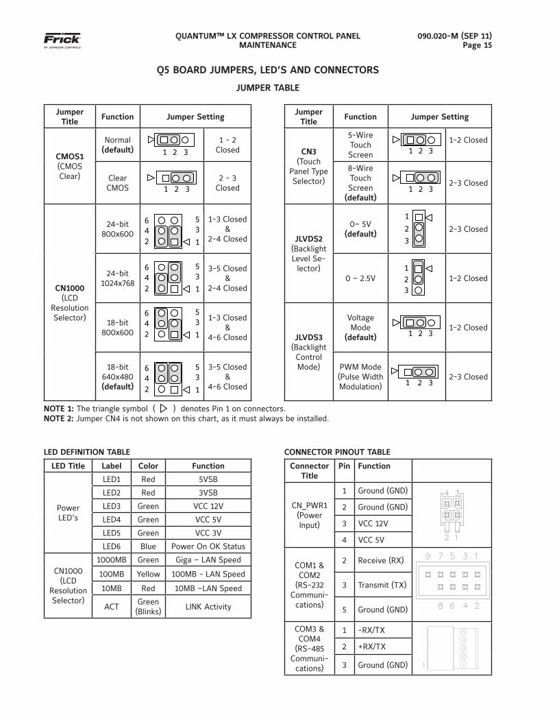
JUMPER TABLE
Jumper Title
Function Jumper SettingJumper
TitleFunction Jumper Setting
CMOS1 (CMOS Clear)
Normal (default)
1 2 3
1 - 2 Closed CN3
(Touch Panel Type Selector)
5-Wire Touch Screen
1 2 3
1-2 Closed
Clear CMOS
1 2 3
2 - 3 Closed
8-Wire Touch Screen
(default)
1 2 3
2-3 Closed
CN1000 (LCD
Resolution Selector)
24-bit 800x600
6
4
2
5 3
1
1-3 Closed &
2-4 Closed JLVDS2(Backlight Level Se-
lector)
0– 5V(default)
1
2
3 2-3 Closed
24-bit 1024x768
6
4
2
5 3
1
3-5 Closed&
2-4 Closed0 – 2.5V
1
2
3
1-2 Closed
18-bit 800x600
6
4
2
5 3
1
1-3 Closed&
4-6 Closed JLVDS3(Backlight Control Mode)
Voltage Mode
(default)
1 2 3 1-2 Closed
18-bit 640x480(default)
6
4
2
5 3
1
3-5 Closed&
4-6 Closed
PWM Mode(Pulse Width Modulation)
1 2 3
2-3 Closed
NOTE 1: The triangle symbol ( ) denotes Pin 1 on connectors.NOTE 2: Jumper CN4 is not shown on this chart, as it must always be installed.
LED DEFINITION TABLE
LED Title Label Color Function
Power LED’s
LED1 Red 5VSB
LED2 Red 3VSB
LED3 Green VCC 12V
LED4 Green VCC 5V
LED5 Green VCC 3V
LED6 Blue Power On OK Status
CN1000 (LCD
Resolution Selector)
1000MB Green Giga – LAN Speed
100MB Yellow 100MB - LAN Speed
10MB Red 10MB –LAN Speed
ACTGreen (Blinks)
LINK Activity
Q5 BOARD JUMPERS, LED’S AND CONNECTORS
CONNECTOR PINOUT TABLE
Connector Title
Pin Function
CN_PWR1(Power Input)
1 Ground (GND)
2 Ground (GND)
3 VCC 12V
4 VCC 5V
COM1 & COM2
(RS-232 Communi-cations)
2 Receive (RX)
3 Transmit (TX)
5 Ground (GND)
COM3 & COM4
(RS-485 Communi-cations)
1 -RX/TX
2 +RX/TX
3 Ground (GND)
QUANTUM™ LX COMPRESSOR CONTROL PANELMAINTENANCE
090.020-M (SEP 11)Page 16
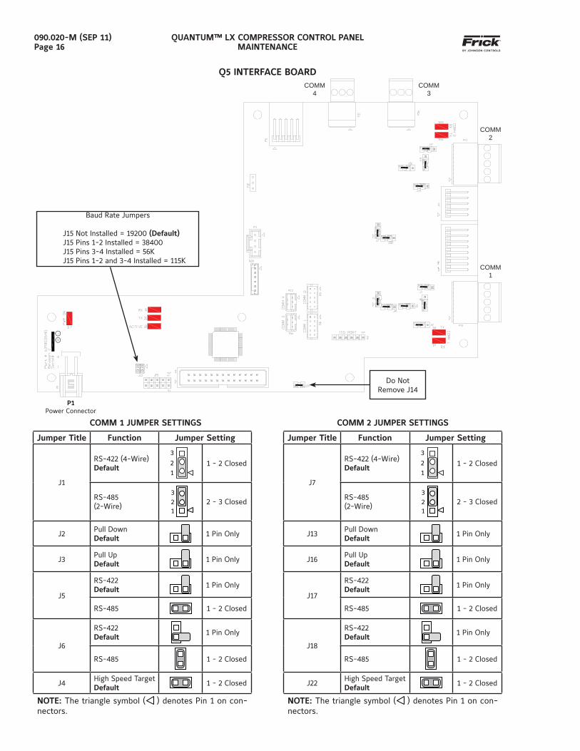
Q5 INTERFACE BOARD
COMM 1 JUMPER SETTINGS COMM 2 JUMPER SETTINGS
Jumper Title Function Jumper Setting
J7
RS-422 (4-Wire)Default
3
2
1 1 - 2 Closed
RS-485(2-Wire)
3
2
1 2 - 3 Closed
J13Pull DownDefault
1 Pin Only
J16Pull UpDefault
1 Pin Only
J17
RS-422Default
1 Pin Only
RS-485 1 - 2 Closed
J18
RS-422Default
1 Pin Only
RS-485 1 - 2 Closed
J22High Speed TargetDefault
1 - 2 Closed
NOTE: The triangle symbol (
) denotes Pin 1 on con-nectors.
P1Power Connector
Jumper Title Function Jumper Setting
J1
RS-422 (4-Wire)Default
3
2
1 1 - 2 Closed
RS-485(2-Wire)
3
2
1 2 - 3 Closed
J2Pull DownDefault
1 Pin Only
J3Pull UpDefault
1 Pin Only
J5
RS-422Default
1 Pin Only
RS-485 1 - 2 Closed
J6
RS-422Default
1 Pin Only
RS-485 1 - 2 Closed
J4High Speed TargetDefault
1 - 2 Closed
NOTE: The triangle symbol (
) denotes Pin 1 on con-nectors.
Do NotRemove J14
Baud Rate Jumpers
J15 Not Installed = 19200 (Default)J15 Pins 1-2 Installed = 38400J15 Pins 3-4 Installed = 56KJ15 Pins 1-2 and 3-4 Installed = 115K
COMM 4
COMM 3
COMM 2
COMM 1
QUANTUM™ LX COMPRESSOR CONTROL PANELMAINTENANCE
090.020-M (SEP 11)Page 17
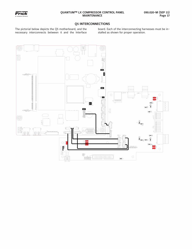
Q5 INTERCONNECTIONS
The pictorial below depicts the Q5 motherboard, and the necessary interconnects between it and the Interface
board. Each of the interconnecting harnesses must be in-stalled as shown for proper operation.
QUANTUM™ LX COMPRESSOR CONTROL PANELMAINTENANCE
090.020-M (SEP 11)Page 18
POWER SUPPLY (Q5)
DESCRIPTION
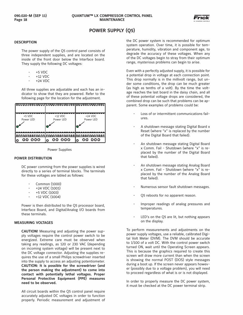
The power supply of the Q5 control panel consists of three independent supplies, and are located on the inside of the front door below the Interface board. They supply the following DC voltages:
• +5 VDC• +12 VDC• +24 VDC
All three supplies are adjustable and each has an in-dicator to show that they are powered. Refer to the following page for the location for the adjustment.
Power Supplies
POWER DISTRIBUTION
DC power comming from the power supplies is wired directly to a series of terminal blocks. The terminals for these voltages are labled as follows:
• Common (1000)• +24 VDC (1001)• +5 VDC (1003)• +12 VDC (1004)
Power is then distributed to the Q5 processor board, Interface Board, and Digital/Analog I/O boards from these terminals.
MEASURING VOLTAGES
CAUTION! Measuring and adjusting the power sup-ply voltages require the control power switch to be energized. Extreme care must be observed when taking any readings, as 120 or 230 VAC (depending on incoming system voltage) will be present next to the DC voltage connector. Adjusting the supplies re-quires the use of a small Philips screwdriver inserted into the supply to access an adjusting potentiometer. CAUTION: It is possible for the screwdriver (and the person making the adjustment) to come into contact with potentially lethal voltages. Proper Personal Protective Equipment (PPE) measures need to be observed.
All circuit boards within the Q5 control panel require accurately adjusted DC voltages in order to function properly. Periodic measurement and adjustment of
+5 VDCPower LED
+12 VDCPower LED
+24 VDCPower LED
the DC power system is recommended for optimum system operation. Over time, it is possible for tem-perature, humidity, vibration and component age, to degrade the accuracy of these voltages. When any of the DC voltages begin to stray from their optimum range, mysterious problems can begin to arise.
Even with a perfectly adjusted supply, it is possible for a potential drop in voltage at each connection point. This drop normally is in the millivolt range, but un-der some conditions, the drop can be much greater (as high as tenths of a volt). By the time the volt-age reaches the last board in the daisy chain, and all of these potential voltage drops are considered, the combined drop can be such that problems can be ap-parent. Some examples of problems could be:
• Loss of or intermittent communications fail-ures.
• A shutdown message stating Digital Board x Reset (where “x” is replaced by the number of the Digital Board that failed).
• An shutdown message stating Digital Board x Comm. Fail - Shutdown (where “x” is re-placed by the number of the Digital Board that failed).
• An shutdown message stating Analog Board x Comm. Fail - Shutdown (where “x” is re-placed by the number of the Analog Board that failed).
• Numerous sensor fault shutdown messages.
• Q5 reboots for no apparent reason.
• Improper readings of analog pressures and temperatures.
• LED's on the Q5 are lit, but nothing appears on the display.
To perform measurements and adjustments on the power supply voltages, use a reliable, calibrated Digi-tal Volt Meter (DVM). The DVM should be accurate to 1/100 of a volt DC. With the control power switch turned ON, wait until the Operating Screen appears. This is because the graphics required to create this screen will draw more current than when the screen is showing the normal POST (DOS) style messages during a boot up. If the screen never appears howev-er (possibly due to a voltage problem), you will need to proceed regardless of what is or is not displayed.
In order to properly measure the DC power system, it must be checked at the DC power terminal strip.
QUANTUM™ LX COMPRESSOR CONTROL PANELMAINTENANCE
090.020-M (SEP 11)Page 19
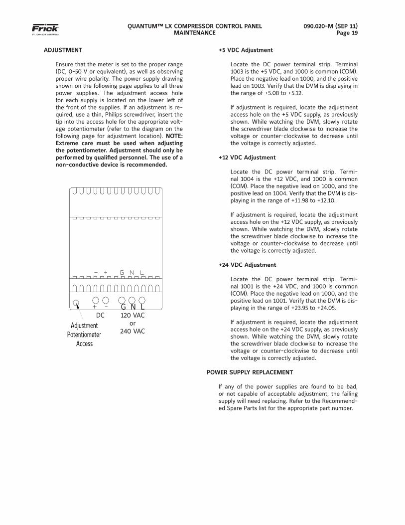
ADJUSTMENT
Ensure that the meter is set to the proper range (DC, 0-50 V or equivalent), as well as observing proper wire polarity. The power supply drawing shown on the following page applies to all three power supplies. The adjustment access hole for each supply is located on the lower left of the front of the supplies. If an adjustment is re-quired, use a thin, Philips screwdriver, insert the tip into the access hole for the appropriate volt-age potentiometer (refer to the diagram on the following page for adjustment location). NOTE: Extreme care must be used when adjusting the potentiometer. Adjustment should only be performed by qualifi ed personnel. The use of a non-conductive device is recommended.
+5 VDC Adjustment
Locate the DC power terminal strip. Terminal 1003 is the +5 VDC, and 1000 is common (COM).Place the negative lead on 1000, and the positive lead on 1003. Verify that the DVM is displaying in the range of +5.08 to +5.12.
If adjustment is required, locate the adjustment access hole on the +5 VDC supply, as previously shown. While watching the DVM, slowly rotate the screwdriver blade clockwise to increase the voltage or counter-clockwise to decrease until the voltage is correctly adjusted.
+12 VDC Adjustment
Locate the DC power terminal strip. Termi-nal 1004 is the +12 VDC, and 1000 is common (COM). Place the negative lead on 1000, and the positive lead on 1004. Verify that the DVM is dis-playing in the range of +11.98 to +12.10.
If adjustment is required, locate the adjustment access hole on the +12 VDC supply, as previously shown. While watching the DVM, slowly rotate the screwdriver blade clockwise to increase the voltage or counter-clockwise to decrease until the voltage is correctly adjusted.
+24 VDC Adjustment
Locate the DC power terminal strip. Termi-nal 1001 is the +24 VDC, and 1000 is common (COM). Place the negative lead on 1000, and the positive lead on 1001. Verify that the DVM is dis-playing in the range of +23.95 to +24.05.
If adjustment is required, locate the adjustment access hole on the +24 VDC supply, as previously shown. While watching the DVM, slowly rotate the screwdriver blade clockwise to increase the voltage or counter-clockwise to decrease until the voltage is correctly adjusted.
POWER SUPPLY REPLACEMENT
If any of the power supplies are found to be bad, or not capable of acceptable adjustment, the failing supply will need replacing. Refer to the Recommend-ed Spare Parts list for the appropriate part number.
+ -DC
G N L120 VAC
or240 VAC
QUANTUM™ LX COMPRESSOR CONTROL PANELMAINTENANCE
090.020-M (SEP 11)Page 20
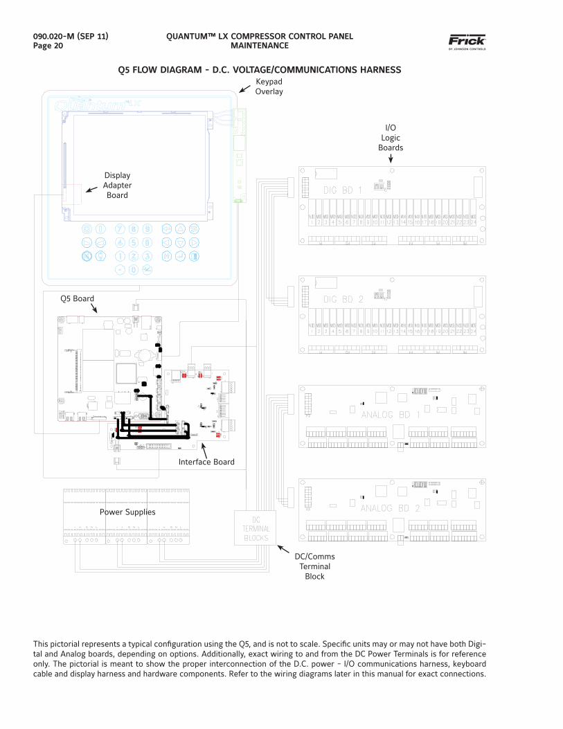
Q5 FLOW DIAGRAM - D.C. VOLTAGE/COMMUNICATIONS HARNESS
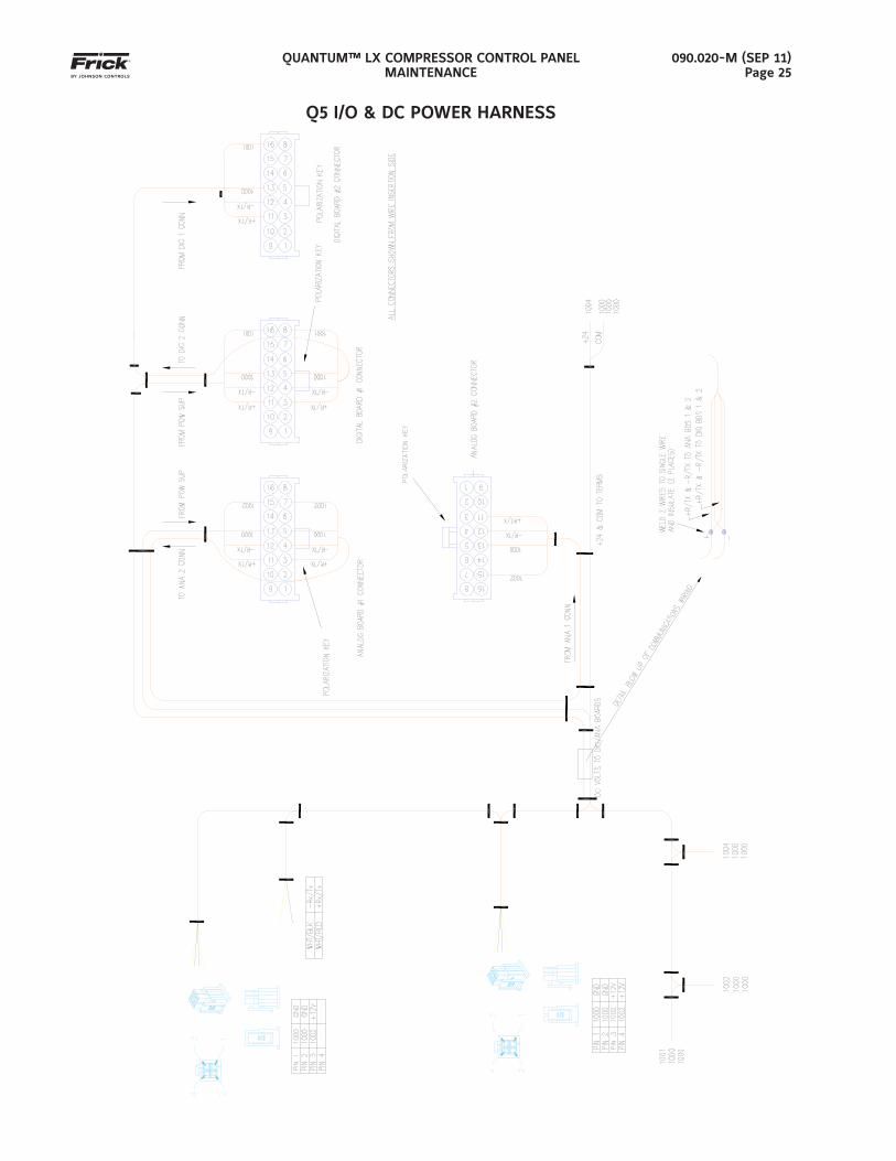
This pictorial represents a typical confi guration using the Q5, and is not to scale. Specifi c units may or may not have both Digi-tal and Analog boards, depending on options. Additionally, exact wiring to and from the DC Power Terminals is for reference only. The pictorial is meant to show the proper interconnection of the D.C. power - I/O communications harness, keyboard cable and display harness and hardware components. Refer to the wiring diagrams later in this manual for exact connections.
Display Adapter Board
KeypadOverlay
I/OLogic
Boards
DC/CommsTerminal
Block
Power Supplies
Interface Board
Q5 Board
QUANTUM™ LX COMPRESSOR CONTROL PANELMAINTENANCE
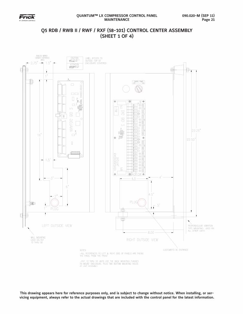
090.020-M (SEP 11)Page 21
Q5 RDB / RWB II / RWF / RXF (58-101) CONTROL CENTER ASSEMBLY(SHEET 1 OF 4)
This drawing appears here for reference purposes only, and is subject to change without notice. When installing, or ser-vicing equipment, always refer to the actual drawings that are included with the control panel for the latest information.
QUANTUM™ LX COMPRESSOR CONTROL PANELMAINTENANCE
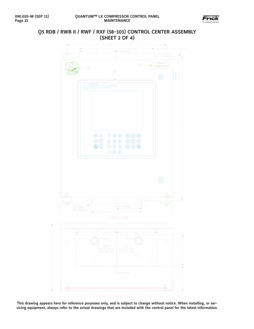
090.020-M (SEP 11)Page 22
Q5 RDB / RWB II / RWF / RXF (58-101) CONTROL CENTER ASSEMBLY(SHEET 2 OF 4)
This drawing appears here for reference purposes only, and is subject to change without notice. When installing, or ser-vicing equipment, always refer to the actual drawings that are included with the control panel for the latest information.
QUANTUM™ LX COMPRESSOR CONTROL PANELMAINTENANCE
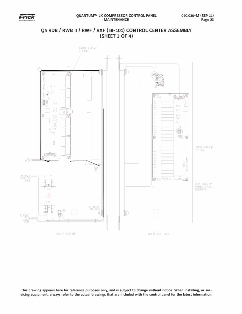
090.020-M (SEP 11)Page 23
Q5 RDB / RWB II / RWF / RXF (58-101) CONTROL CENTER ASSEMBLY(SHEET 3 OF 4)
This drawing appears here for reference purposes only, and is subject to change without notice. When installing, or ser-vicing equipment, always refer to the actual drawings that are included with the control panel for the latest information.
QUANTUM™ LX COMPRESSOR CONTROL PANELMAINTENANCE
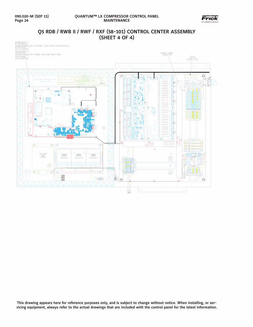
090.020-M (SEP 11)Page 24
Q5 RDB / RWB II / RWF / RXF (58-101) CONTROL CENTER ASSEMBLY(SHEET 4 OF 4)
This drawing appears here for reference purposes only, and is subject to change without notice. When installing, or ser-vicing equipment, always refer to the actual drawings that are included with the control panel for the latest information.
QUANTUM™ LX COMPRESSOR CONTROL PANELMAINTENANCE
090.020-M (SEP 11)Page 25
Q5 I/O & DC POWER HARNESS
QUANTUM™ LX COMPRESSOR CONTROL PANELMAINTENANCE
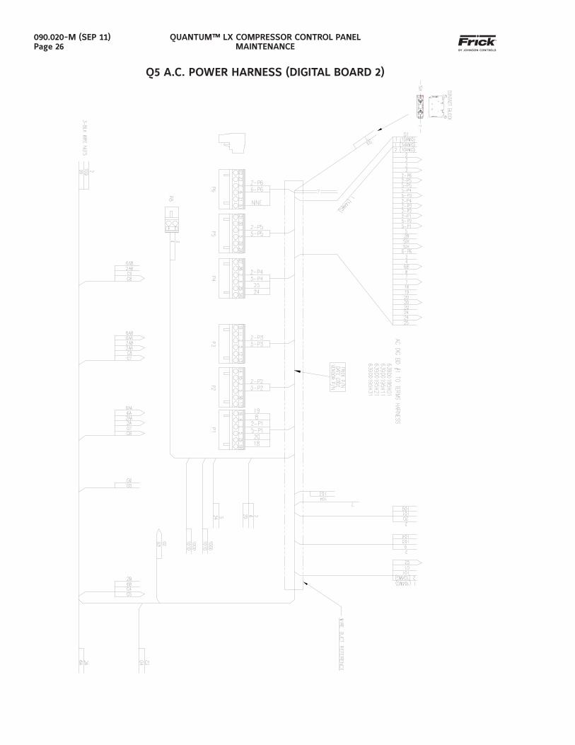
090.020-M (SEP 11)Page 26
Q5 A.C. POWER HARNESS (DIGITAL BOARD 2)
QUANTUM™ LX COMPRESSOR CONTROL PANELMAINTENANCE
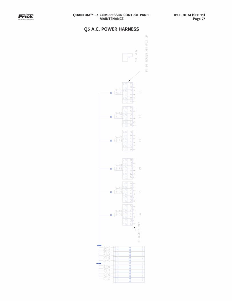
090.020-M (SEP 11)Page 27
Q5 A.C. POWER HARNESS
QUANTUM™ LX COMPRESSOR CONTROL PANELMAINTENANCE
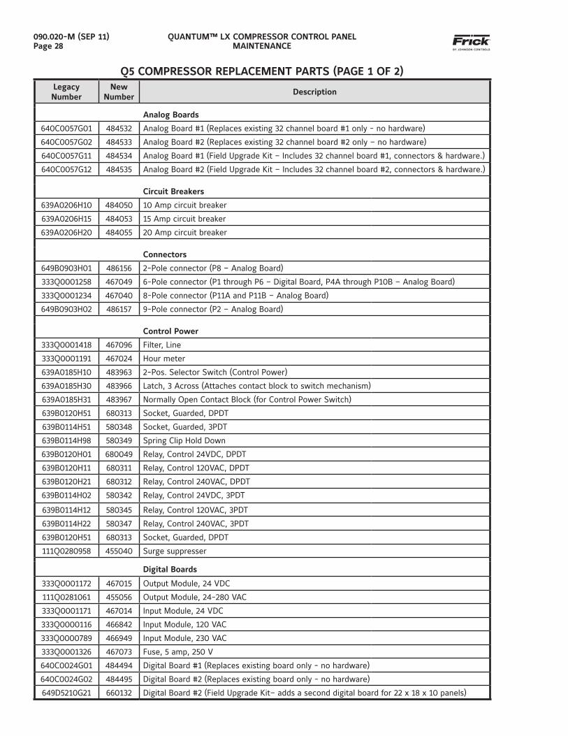
090.020-M (SEP 11)Page 28
Q5 COMPRESSOR REPLACEMENT PARTS (PAGE 1 OF 2)LegacyNumber
NewNumber
Description
Analog Boards
640C0057G01 484532 Analog Board #1 (Replaces existing 32 channel board #1 only - no hardware)
640C0057G02 484533 Analog Board #2 (Replaces existing 32 channel board #2 only – no hardware)
640C0057G11 484534 Analog Board #1 (Field Upgrade Kit – Includes 32 channel board #1, connectors & hardware.)
640C0057G12 484535 Analog Board #2 (Field Upgrade Kit – Includes 32 channel board #2, connectors & hardware.)
Circuit Breakers
639A0206H10 484050 10 Amp circuit breaker
639A0206H15 484053 15 Amp circuit breaker
639A0206H20 484055 20 Amp circuit breaker
Connectors
649B0903H01 486156 2-Pole connector (P8 – Analog Board)
333Q0001258 467049 6-Pole connector (P1 through P6 – Digital Board, P4A through P10B – Analog Board)
333Q0001234 467040 8-Pole connector (P11A and P11B – Analog Board)
649B0903H02 486157 9-Pole connector (P2 – Analog Board)
Control Power
333Q0001418 467096 Filter, Line
333Q0001191 467024 Hour meter
639A0185H10 483963 2-Pos. Selector Switch (Control Power)
639A0185H30 483966 Latch, 3 Across (Attaches contact block to switch mechanism)
639A0185H31 483967 Normally Open Contact Block (for Control Power Switch)
639B0120H51 680313 Socket, Guarded, DPDT
639B0114H51 580348 Socket, Guarded, 3PDT
639B0114H98 580349 Spring Clip Hold Down
639B0120H01 680049 Relay, Control 24VDC, DPDT
639B0120H11 680311 Relay, Control 120VAC, DPDT
639B0120H21 680312 Relay, Control 240VAC, DPDT
639B0114H02 580342 Relay, Control 24VDC, 3PDT
639B0114H12 580345 Relay, Control 120VAC, 3PDT
639B0114H22 580347 Relay, Control 240VAC, 3PDT
639B0120H51 680313 Socket, Guarded, DPDT
111Q0280958 455040 Surge suppresser
Digital Boards
333Q0001172 467015 Output Module, 24 VDC
111Q0281061 455056 Output Module, 24-280 VAC
333Q0001171 467014 Input Module, 24 VDC
333Q0000116 466842 Input Module, 120 VAC
333Q0000789 466949 Input Module, 230 VAC
333Q0001326 467073 Fuse, 5 amp, 250 V
640C0024G01 484494 Digital Board #1 (Replaces existing board only - no hardware)
640C0024G02 484495 Digital Board #2 (Replaces existing board only - no hardware)
649D5210G21 660132 Digital Board #2 (Field Upgrade Kit– adds a second digital board for 22 x 18 x 10 panels)
QUANTUM™ LX COMPRESSOR CONTROL PANELMAINTENANCE
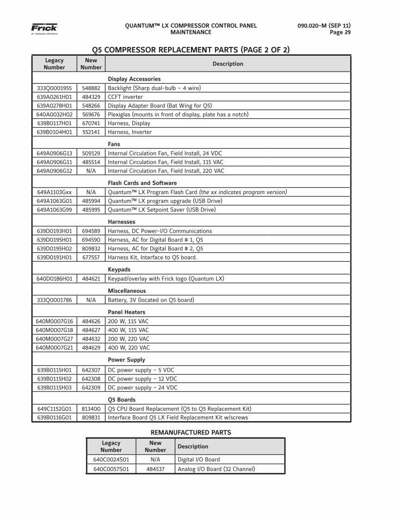
090.020-M (SEP 11)Page 29
LegacyNumber
NewNumber
Description
Display Accessories
333Q0001955 548882 Backlight (Sharp dual-bulb – 4 wire)
639A0261H01 484329 CCFT inverter
639A0278H01 548266 Display Adapter Board (Bat Wing for Q5)
640A0032H02 569676 Plexiglas (mounts in front of display, plate has a notch)
639B0117H01 670741 Harness, Display
639B0104H01 552141 Harness, Inverter
Fans
649A0906G13 509129 Internal Circulation Fan, Field Install, 24 VDC
649A0906G11 485514 Internal Circulation Fan, Field Install, 115 VAC
649A0906G12 N/A Internal Circulation Fan, Field Install, 220 VAC
Flash Cards and Software
649A1103Gxx N/A Quantum™ LX Program Flash Card (the xx indicates program version)649A1063G01 485994 Quantum™ LX program upgrade (USB Drive)
649A1063G99 485995 Quantum™ LX Setpoint Saver (USB Drive)
Harnesses
639D0193H01 694589 Harness, DC Power-I/O Communications
639D0195H01 694590 Harness, AC for Digital Board # 1, Q5
639D0195H02 809832 Harness, AC for Digital Board # 2, Q5
639D0191H01 677557 Harness Kit, Interface to Q5 board.
Keypads
640D0186H01 484621 Keypad/overlay with Frick logo (Quantum LX)
Miscellaneous
333Q0001786 N/A Battery, 3V (located on Q5 board)
Panel Heaters
640M0007G16 484626 200 W, 115 VAC
640M0007G18 484627 400 W, 115 VAC
640M0007G27 484632 200 W, 220 VAC
640M0007G21 484629 400 W, 220 VAC
Power Supply
639B0115H01 642307 DC power supply – 5 VDC
639B0115H02 642308 DC power supply – 12 VDC
639B0115H03 642309 DC power supply – 24 VDC
Q5 Boards
649C1152G01 813400 Q5 CPU Board Replacement (Q5 to Q5 Replacement Kit)
639B0116G01 809831 Interface Board Q5 LX Field Replacement Kit w/screws
REMANUFACTURED PARTS
LegacyNumber
NewNumber
Description
640C0024S01 N/A Digital I/O Board
640C0057S01 484537 Analog I/O Board (32 Channel)
Q5 COMPRESSOR REPLACEMENT PARTS (PAGE 2 OF 2)

QUANTUM™ LX COMPRESSOR CONTROL PANELMAINTENANCE
090.020-M (SEP 11)Page 30
NOTES:
QUANTUM™ LX COMPRESSOR CONTROL PANELMAINTENANCE
090.020-M (SEP 11)Page 31
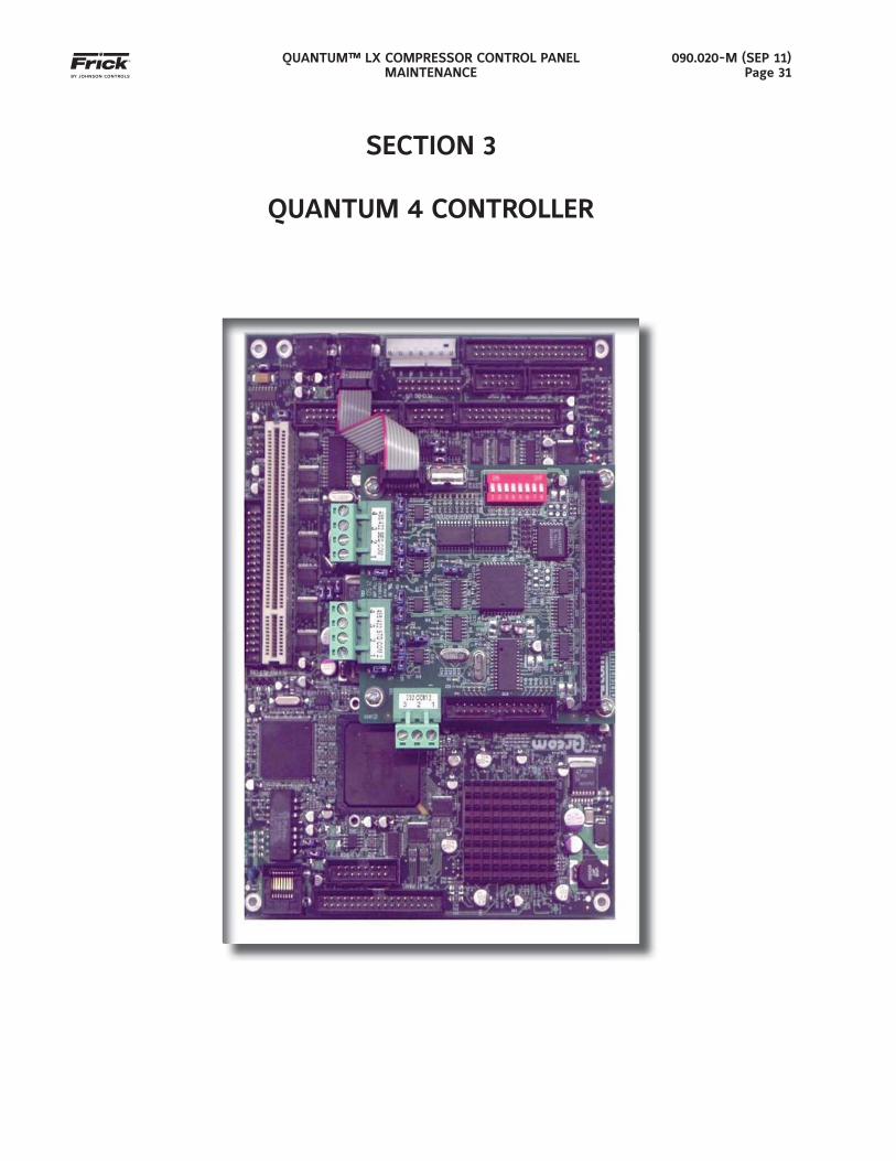
SECTION 3
QUANTUM 4 CONTROLLER
QUANTUM™ LX COMPRESSOR CONTROL PANELMAINTENANCE
090.020-M (SEP 11)Page 32
in the upper left corner of the screen as the boot sequence progresses.
• Just before fully booting, a Loading bar will appear at the bottom of the screen, show-ing the percent of load that has completed.
• The Operating Status screen will appear.
After the Quantum 4 has properly powered up, the following sequence of events is indicative of proper communication to the analog and digital boards:
• The Analog and Digital I/O boards TX/RX lights should be blinking.
• Each I/O board should have the power LED lighted and the Active LED should be blink-ing.
WHAT IF THE OPERATING STATUS SCREEN IS NOT SHOWN
If the Operating Status screen is not shown, check the following items:
1. If no LED’s are lit, then check AC and DC power. Refer to the Power Supply section.
2. Check if the lighting of the LED’s is occur-ring as described in the What Should Occur When Applying Powering section.
• If the powering up sequence continues to repeat without displaying the Op-erating Status screen, then there is a booting problem.
3. Check for bad connections.
4. Check if an error message is displayed when booting.
• Be sure to write down any error mes-sages exactly as they appear.
5. Check that the software is OK:
• Is the correct software installed?
• Did you just install new software?
6. Remove Flashcard and reboot. This will cause the Quantum 4 to boot under a pre-LX operating software. If it boots prop-erly under this older software, then trying re-booting from the Flashcard again. If it doesn’t boot with the card, then the Flash-card could be corrupted, and needs to be replaced.
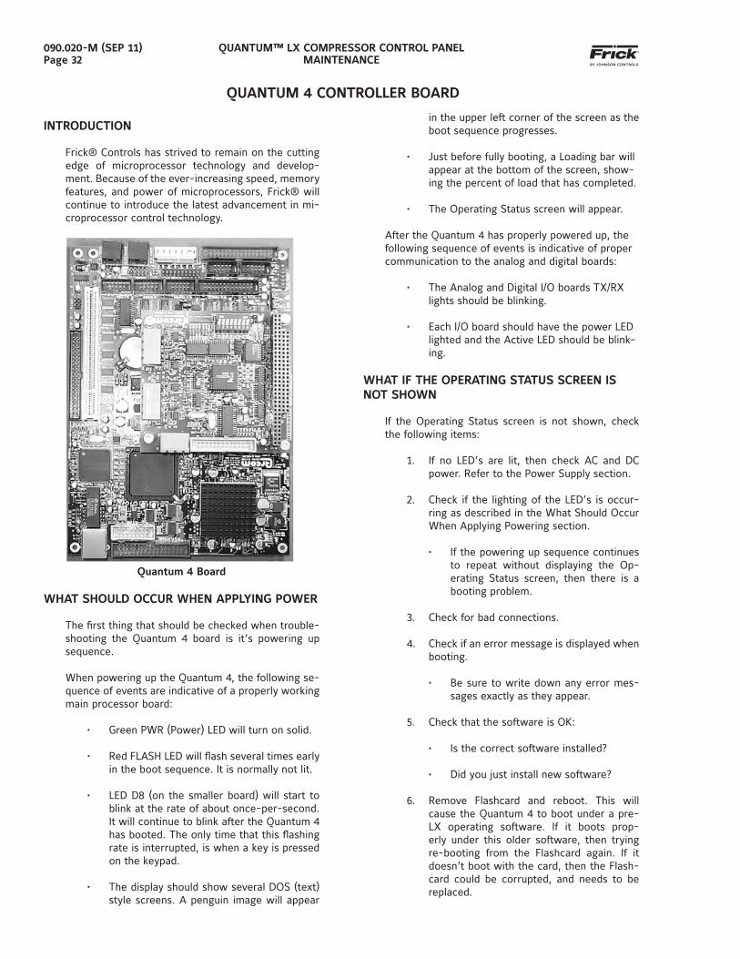
INTRODUCTION
Frick® Controls has strived to remain on the cutting edge of microprocessor technology and develop-ment. Because of the ever-increasing speed, memory features, and power of microprocessors, Frick® will continue to introduce the latest advancement in mi-croprocessor control technology.
Quantum 4 Board
WHAT SHOULD OCCUR WHEN APPLYING POWER
The fi rst thing that should be checked when trouble-shooting the Quantum 4 board is it’s powering up sequence.
When powering up the Quantum 4, the following se-quence of events are indicative of a properly working main processor board:
• Green PWR (Power) LED will turn on solid.
• Red FLASH LED will fl ash several times early in the boot sequence. It is normally not lit.
• LED D8 (on the smaller board) will start to blink at the rate of about once-per-second. It will continue to blink after the Quantum 4 has booted. The only time that this fl ashing rate is interrupted, is when a key is pressed on the keypad.
• The display should show several DOS (text) style screens. A penguin image will appear
QUANTUM 4 CONTROLLER BOARD
QUANTUM™ LX COMPRESSOR CONTROL PANELMAINTENANCE
090.020-M (SEP 11)Page 33
7. Check the display. If the Quantum 4 board is booting but you have no display, check the following:
• Check the LCD backlight tube. Look very closely at the display to see if any-thing is visible in the dark screen. Using a beam type source of good lighting, such as a fl ashlight, look for any ghost type image. If it appears that there is something on the screen but very dark, the problem may be with the LCD back-light tube. On the LG Philips, NEC and Sharp displays this tube is fi eld replace-able. On the Samsung LCD display it is not available and the display will have to be replaced. There may be a sticker on the display mounting plate. If there is, it will have a part number that de-scribes the type of display. If there is no sticker, you must take the display apart to identify the display manufacturer.
• Verify that both the display cable and the inverter cable are fi rmly seated. These cables both originate from the same connector on the Quantum 4. It may be necessary to remove the video cable from the back of the LCD display and re-seat it to be sure it is connected properly. Note: This is a small connec-tor and caution should be observed so that it is not damaged due to excessive force.
• Refer to the Operator Interface section and check that the LCD, LCD cable, and software versions are matched correct-ly.
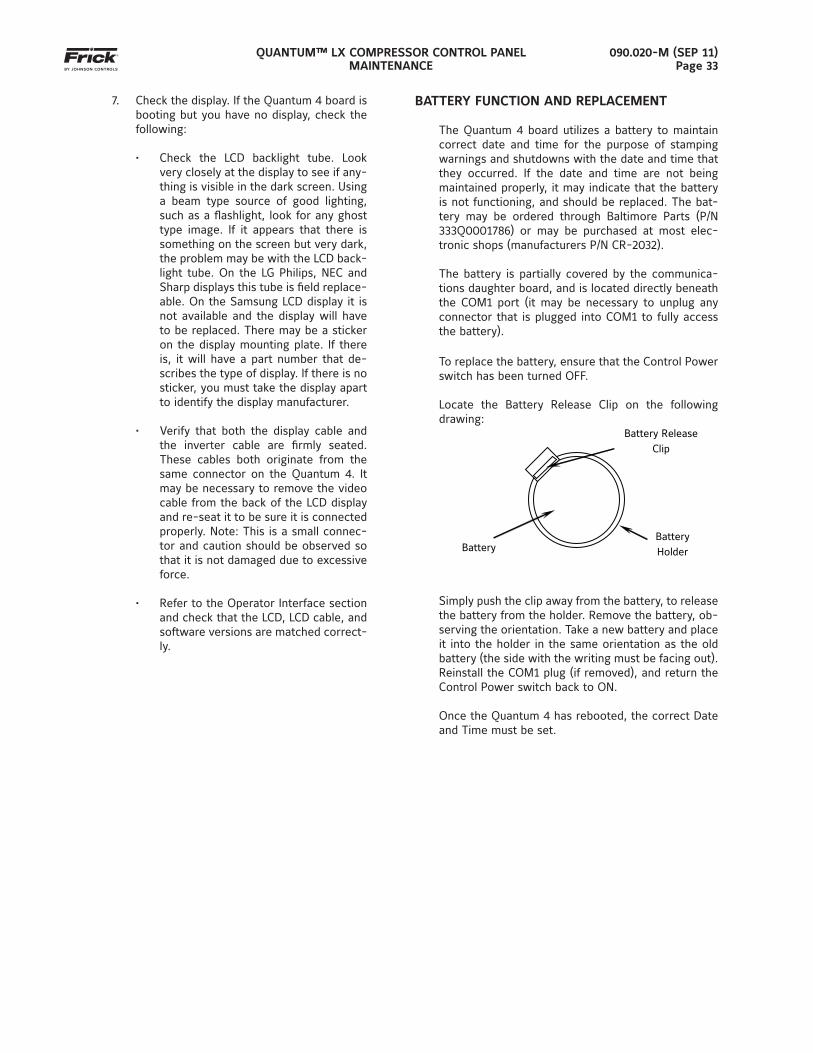
BATTERY FUNCTION AND REPLACEMENT
The Quantum 4 board utilizes a battery to maintain correct date and time for the purpose of stamping warnings and shutdowns with the date and time that they occurred. If the date and time are not being maintained properly, it may indicate that the battery is not functioning, and should be replaced. The bat-tery may be ordered through Baltimore Parts (P/N 333Q0001786) or may be purchased at most elec-tronic shops (manufacturers P/N CR-2032).
The battery is partially covered by the communica-tions daughter board, and is located directly beneath the COM1 port (it may be necessary to unplug any connector that is plugged into COM1 to fully access the battery).
To replace the battery, ensure that the Control Power switch has been turned OFF.
Locate the Battery Release Clip on the following drawing:
Battery
Battery Release Clip
Battery Holder
Simply push the clip away from the battery, to release the battery from the holder. Remove the battery, ob-serving the orientation. Take a new battery and place it into the holder in the same orientation as the old battery (the side with the writing must be facing out). Reinstall the COM1 plug (if removed), and return the Control Power switch back to ON.
Once the Quantum 4 has rebooted, the correct Date and Time must be set.
QUANTUM™ LX COMPRESSOR CONTROL PANELMAINTENANCE
090.020-M (SEP 11)Page 34
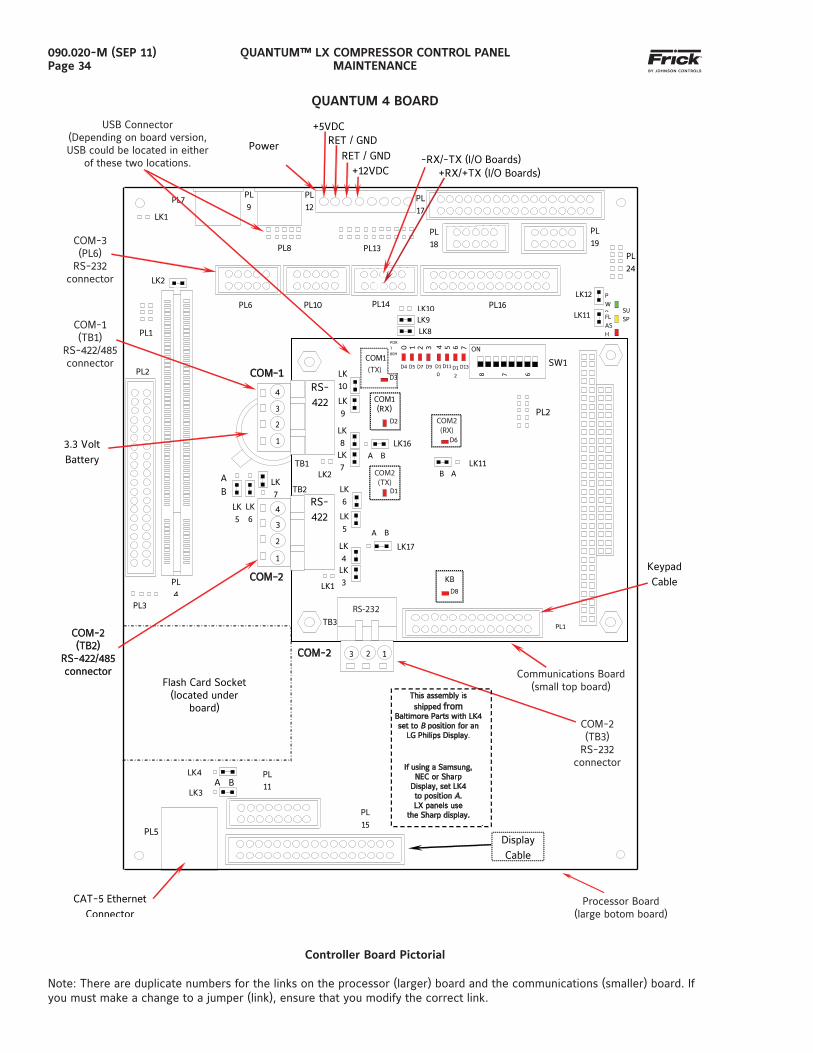
QUANTUM 4 BOARD
3.3 Volt Battery
PL8
LK1
PL9
PL1
LK2
Flash Card Socket(located under
board)
PL3
PL13
PL7 PL17
PL12
PL19
PL18
PL14
PL10 PL6
PL2
PL4
PWR SU
SP FLASH
LK11
LK12
PL
24
PL3
PL4
LK9 LK8
LK10 PL16
PL5
PL11
LK3 A B
LK4
PL
15
TB1
TB2
LK2
COM-2
TB3
RS-232
3 2 1
D3
LK16
A B
A B
COM-2
LK6
B
A
LK
5
LK
7
PL2
COM1
3 4 5 6 7 0 1 2
D9 D1
0
D11 D1
2
PORT 80H
D4 D5 D7 D13 SW1
ON
8
7
6 COM-1
1
2
3
4
1
2
4 RS-422
LK
4 LK3
LK6
LK
5
D1
D8
LK17
RS-422
LK8
LK
7
LK10
LK9
D6
D2
LK11 B A
PL1
COM1(RX)
KB
3
LK1
CAT-5 Ethernet Connector
This assembly isshipped from
Baltimore Parts with LK4set to B position for an
LG Philips Display.
If using a Samsung,NEC or Sharp
Display, set LK4to position A.LX panels use
the Sharp display.
ADisplay Cable
Keypad Cable
COM-2(TB2)
RS-422/485connector
Power
+5VDC
+12VDC
RET / GND
RET / GND
+RX/+TX (I/O Boards) -RX/-TX (I/O Boards)
(TX)
COM2(TX)
COM2(RX)
COM-2(TB2)
RS-422/485connector
COM-1(TB1)
RS-422/485connector
COM-3(PL6)
RS-232connector
USB Connector(Depending on board version,USB could be located in either
of these two locations.
COM-2(TB3)
RS-232connector
Processor Board(large botom board)
Communications Board(small top board)
Controller Board Pictorial
Note: There are duplicate numbers for the links on the processor (larger) board and the communications (smaller) board. If you must make a change to a jumper (link), ensure that you modify the correct link.
QUANTUM™ LX COMPRESSOR CONTROL PANELMAINTENANCE
090.020-M (SEP 11)Page 35
QUANTUM 4 BOARD SETTINGS
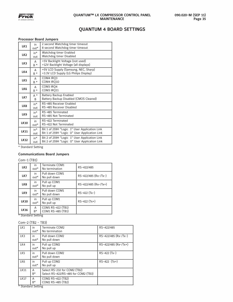
Processor Board Jumpers
LK1in
out*2 second Watchdog timer timeout8 second Watchdog timer timeout
LK2in*out
Watchdog timer EnabledWatchdog timer Disabled
LK3A
B *+5V Backlight Voltage (not used)+12V Backlight Voltage (all displays)
LK4A
B *+5V LCD Supply (Samsung, NEC, Sharp)+3.3V LCD Supply (LG Philips Display)
LK5A
B *COM4 IRQ3COM4 IRQ10
LK6A
B *COM3 IRQ4COM3 IRQ11
LK7A *B
Battery Backup EnabledBattery Backup Disabled (CMOS Cleared)
LK8in*out
RS-485 Receiver EnabledRS-485 Receiver Disabled
LK9in*out
RS-485 TerminatedRS-485 Not Terminated
LK10in
out*RS-422 Terminated RS-422 Not Terminated
LK11in*out
Bit 1 of 259H “Logic 1” User Application LinkBit 1 of 259H “Logic 0” User Application Link
LK12in*out
Bit 2 of 259H “Logic 1” User Application LinkBit 2 of 259H “Logic 0” User Application Link
* Standard Setting
Communications Board Jumpers
Com-1 (TB1)
LK2in
out*Terminate COM1No termination RS-422/485
LK7in
out*Pull down COM1 No pull down RS-422/485 (Rx-/Tx-)
LK8in
out*Pull up COM1No pull up RS-422/485 (Rx-/Tx+)
LK9in
out*Pull down COM1No pull down RS-422 (Tx-)
LK10in
out*Pull up COM1No pull up RS-422 (Tx+)
LK16AB*
COM1 RS-422 (TB1)COM1 RS-485 (TB1)
* Standard Setting
Com-2 (TB2 - TB3)LK1 in
out*Terminate COM2No termination
RS-422/485
LK3 inout*
Pull down COM2No pull down
RS-422/485 (Rx-/Tx-)
LK4 inout*
Pull up COM2No pull up
RS-422/485 (Rx-/Tx+)
LK5 inout*
Pull down COM2No pull down
RS-422 (Tx-)
LK6 inout*
Pull up COM2No pull up
RS-422 (Tx+)
LK11 AB*
Select RS-232 for COM2 (TB2)Select RS-422/RS-485 for COM2 (TB3)
LK17 AB*
COM2 RS-422 (TB2) COM2 RS-485 (TB2)
* Standard Setting
QUANTUM™ LX COMPRESSOR CONTROL PANELMAINTENANCE
090.020-M (SEP 11)Page 36
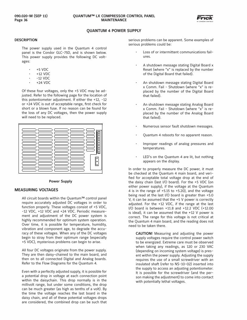
DESCRIPTION
The power supply used in the Quantum 4 control panel is the Condor GLC-75D, and is shown below. This power supply provides the following DC volt-ages:
• +5 VDC• +12 VDC• -12 VDC• +24 VDC
Of these four voltages, only the +5 VDC may be ad-justed. Refer to the following page for the location of this potentiometer adjustment. If either the +12, -12 or +24 VDC is out of acceptable range, fi rst check for short or a blown fuse. If no reason can be found for the loss of any DC voltages, then the power supply will need to be replaced.
Power Supply
MEASURING VOLTAGES
All circuit boards within the Quantum™ control panel require accurately adjusted DC voltages in order to function properly. These voltages consist of +5 VDC, -12 VDC, +12 VDC and +24 VDC. Periodic measure-ment and adjustment of the DC power system is highly recommended for optimum system operation. Over time, it is possible for temperature, humidity, vibration and component age, to degrade the accu-racy of these voltages. When any of the DC voltages begin to stray from their optimum range (especially +5 VDC), mysterious problems can begin to arise.
All four DC voltages originate from the power supply. They are then daisy-chained to the main board, and then on to all connected Digital and Analog boards. Refer to the Flow Diagrams for the Quantum 4.
Even with a perfectly adjusted supply, it is possible for a potential drop in voltage at each connection point within the daisychain. This drop normally is in the millivolt range, but under some conditions, the drop can be much greater (as high as tenths of a volt). By the time the voltage reaches the last board in the daisy chain, and all of these potential voltages drops are considered, the combined drop can be such that
QUANTUM 4 POWER SUPPLY
serious problems can be apparent. Some examples of serious problems could be:
• Loss of or intermittent communications fail-ures.
• A shutdown message stating Digital Board x Reset (where “x” is replaced by the number of the Digital Board that failed).
• An shutdown message stating Digital Board x Comm. Fail - Shutdown (where “x” is re-placed by the number of the Digital Board that failed).
• An shutdown message stating Analog Board x Comm. Fail - Shutdown (where “x” is re-placed by the number of the Analog Board that failed).
• Numerous sensor fault shutdown messages.
• Quantum 4 reboots for no apparent reason.
• Improper readings of analog pressures and temperatures.
• LED's on the Quantum 4 are lit, but nothing appears on the display.
In order to properly measure the DC power, it must be checked at the Quantum 4 main board, and veri-fi ed for acceptable total voltage drop at the end of the daisy chain (last I/O board). For the +5 VDC (on either power supply), if the voltage at the Quantum 4 is in the range of +5.15 to +5.20), and the voltage being read at the last I/O board is greater than +5.0 V, it can be assumed that the +5 V power is correctly adjusted. For the +12 VDC, if the range at the last I/O board is between +11.8 and +12.2 VDC (+12.00 is ideal), it can be assumed that the +12 V power is correct. The range for this voltage is not critical at the Quantum 4 main board, and the reading does not need to be taken there.
CAUTION! Measuring and adjusting the power supply voltages require the control power switch to be energized. Extreme care must be observed when taking any readings, as 120 or 230 VAC (depending on incoming system voltage) is pres-ent within the power supply. Adjusting the supply requires the use of a small screwdriver with an insulated shaft (refer to NS-10-02) inserted into the supply to access an adjusting potentiometer. It is possible for the screwdriver (and the per-son making the adjustment) to come into contact with potentially lethal voltages.
QUANTUM™ LX COMPRESSOR CONTROL PANELMAINTENANCE
090.020-M (SEP 11)Page 37
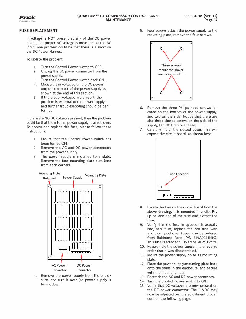
FUSE REPLACEMENT
If voltage is NOT present at any of the DC power points, but proper AC voltage is measured at the AC input, one problem could be that there is a short on the DC Power Harness.
To isolate the problem:
1. Turn the Control Power switch to OFF.2. Unplug the DC power connector from the
power supply.3. Turn the Control Power switch back ON.4. Measure the voltages on the DC power
output connector of the power supply as shown at the end of this section.
5. If the proper voltages are present, the problem is external to the power supply, and further troubleshooting should be per-formed.
If there are NO DC voltages present, then the problem could be that the internal power supply fuse is blown. To access and replace this fuse, please follow these instructions:
1. Ensure that the Control Power switch has been turned OFF.
2. Remove the AC and DC power connectors from the power supply.
3. The power supply is mounted to a plate. Remove the four mounting plate nuts (one from each corner).
AC Power Connector
DC Power Connector
Mounting Plate Nuts (x4)
Mounting Plate Power Supply
4. Remove the power supply from the enclo-sure, and turn it over (so power supply is facing down).
5. Four screws attach the power supply to the mounting plate, remove the four screws.
These screws mount the power supply to the plate
6. Remove the three Philips head screws lo-cated on the bottom of the power supply, and two on the side. Notice that there are also three slotted screws on the side of the supply, DO NOT remove these.
7. Carefully lift of the slotted cover. This will expose the circuit board, as shown here:
Fuse Location.
8. Locate the fuse on the circuit board from the above drawing. It is mounted in a clip. Pry up on one end of the fuse and extract the fuse.
9. Verify that the fuse in question is actually bad, and if so, replace the bad fuse with a known good one. Fuses may be ordered from Baltimore Parts (P/N 649A0954H19). This fuse is rated for 3.15 amps @ 250 volts.
10. Reassemble the power supply in the reverse order that it was disassembled.
11. Mount the power supply on to its mounting plate.
12. Place the power supply/mounting plate back onto the studs in the enclosure, and secure with the mounting nuts.
13. Reattach the AC and DC power harnesses.14. Turn the Control Power switch to ON.15. Verify that DC voltages are now present on
the DC power connector. The 5 VDC may now be adjusted per the adjustment proce-dure on the following page.
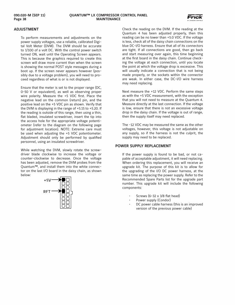
QUANTUM™ LX COMPRESSOR CONTROL PANELMAINTENANCE
090.020-M (SEP 11)Page 38
ADJUSTMENT
To perform measurements and adjustments on the power supply voltages, use a reliable, calibrated Digi-tal Volt Meter (DVM). The DVM should be accurate to 1/100 of a volt DC. With the control power switch turned ON, wait until the Operating Screen appears. This is because the graphics required to create this screen will draw more current than when the screen is showing the normal POST style messages during a boot up. If the screen never appears however (pos-sibly due to a voltage problem), you will need to pro-ceed regardless of what is or is not displayed.
Ensure that the meter is set to the proper range (DC, 0-50 V or equivalent), as well as observing proper wire polarity. Measure the +5 VDC fi rst. Place the negative lead on the common (return) pin, and the positive lead on the +5 VDC pin as shown. Verify that the DVM is displaying in the range of +5.15 to +5.20. If the reading is outside of this range, then using a thin, fl at bladed, insulated screwdriver, insert the tip into the access hole for the appropriate voltage potenti-ometer (refer to the diagram on the following page for adjustment location). NOTE: Extreme care must be used when adjusting the +5 VDC potentiometer. Adjustment should only be performed by qualifi ed personnel, using an insulated screwdriver.
While watching the DVM, slowly rotate the screw-driver blade clockwise to increase the voltage or counter-clockwise to decrease. Once the voltage has been adjusted, remove the DVM probes from the Quantum™, and install them into the white connec-tor on the last I/O board in the daisy chain, as shown below:
+5V
RET
Check the reading on the DVM. If the reading at the Quantum 4 has been adjusted properly, then this reading can be no lower than +5.0 VDC. If the voltage is less, check all of the daisy chain connections on the blue DC-I/O harness. Ensure that all of its connectors are tight. If all connections are good, then go back and start measuring over again, this time beginning at the fi rst board in the daisy chain. Continue check-ing the voltage at each connection, until you locate the point at which the voltage drop is excessive. This will usually indicate a connection that is not being made properly, or the sockets within the connector are weak. In either case, the DC-I/O wire harness may need replacing.
Next measure the +12 VDC. Perform the same steps as with the +5 VDC measurement, with the exception that you will not need to measure at the Quantum 4. Measure directly at the last connection. If the voltage is low, ensure that there is not an excessive voltage drop in the daisy chain. If the voltage is out of range, then the supply itself may need replaced.
The -12 VDC may be measured the same as the other voltages, however, this voltage is not adjustable on any supply, so if the harness is not the culprit, the supply may need to be replaced.
POWER SUPPLY REPLACEMENT
If the power supply is found to be bad, or not ca-pable of acceptable adjustment, it will need replacing. When ordering this replacement, you will receive an upgrade kit. The purpose of this kit is to allow for the upgrading of the I/O DC power harness, at the same time as replacing the power supply. Refer to the Recommended Spare Parts list for the upgrade part number. This upgrade kit will include the following components:
• Screws (6-32 x 3/8 fl at head)• Power supply (Condor)• DC power cable harness (this is an improved
version of the previous power cable)
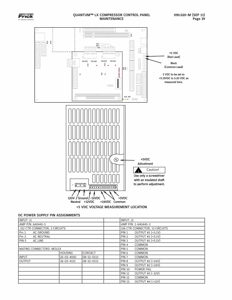
QUANTUM™ LX COMPRESSOR CONTROL PANELMAINTENANCE
090.020-M (SEP 11)Page 39
+5 VDC5 VDC
(Red Lead)(Red Lead)
5 VDC to be set to 5 VDC to be set to
+5.15VDC to 5.20 VDC as +5.15VDC to 5.20 VDC as
measured here.measured here.
BlackBlack
(Common Lead)(Common Lead)
PL3
PL4
120V120V GroundGround +5VDC+5VDC -12VDC12VDC NeutralNeutral CommonCommon +24VDC+24VDC +12VDC+12VDC
J
J2
11
CAUTION !
Use only a screwdriver Use only a screwdriver with an insulated shaft with an insulated shaft to perform adjustmentto perform adjustment..
+5VDC +5VDC AdjustmentAdjustment
Caution!
+5 VDC VOLTAGE MEASUREMENT LOCATION
DC POWER SUPPLY PIN ASSIGNMENTSINPUT: J1 INPUT: J2AMP P/N: 640445-5 AMP P/N: 1-640445-3.312 CTR CONNECTOR, 3 CIRCUITS 156 CTR CONNECTOR, 13 CIRCUITSPin 1 AC GROUND PIN 1 OUTPUT #1 (+5.1V)Pin 3 AC NEUTRAL PIN 2 OUTPUT #1 (+5.1V)PIN 5 AC LINE PIN 3 OUTPUT #1 (+5.1V)
PIN 4 COMMONMATING CONNECTORS: MOLEX PIN 5 COMMON
HOUSING CONTACT PIN 6 COMMONINPUT 26-03-4050 08-52-0113 PIN 7 COMMONOUTPUT 26-03-4131 08-52-0113 PIN 8 OUTPUT #2 (+24V)
PIN 9 OUTPUT #2 (+24V)PIN 10 POWER FAILPIN 11 OUTPUT #3 (-12V)PIN 12 COMMONPIN 13 OUTPUT #4 (+12V)
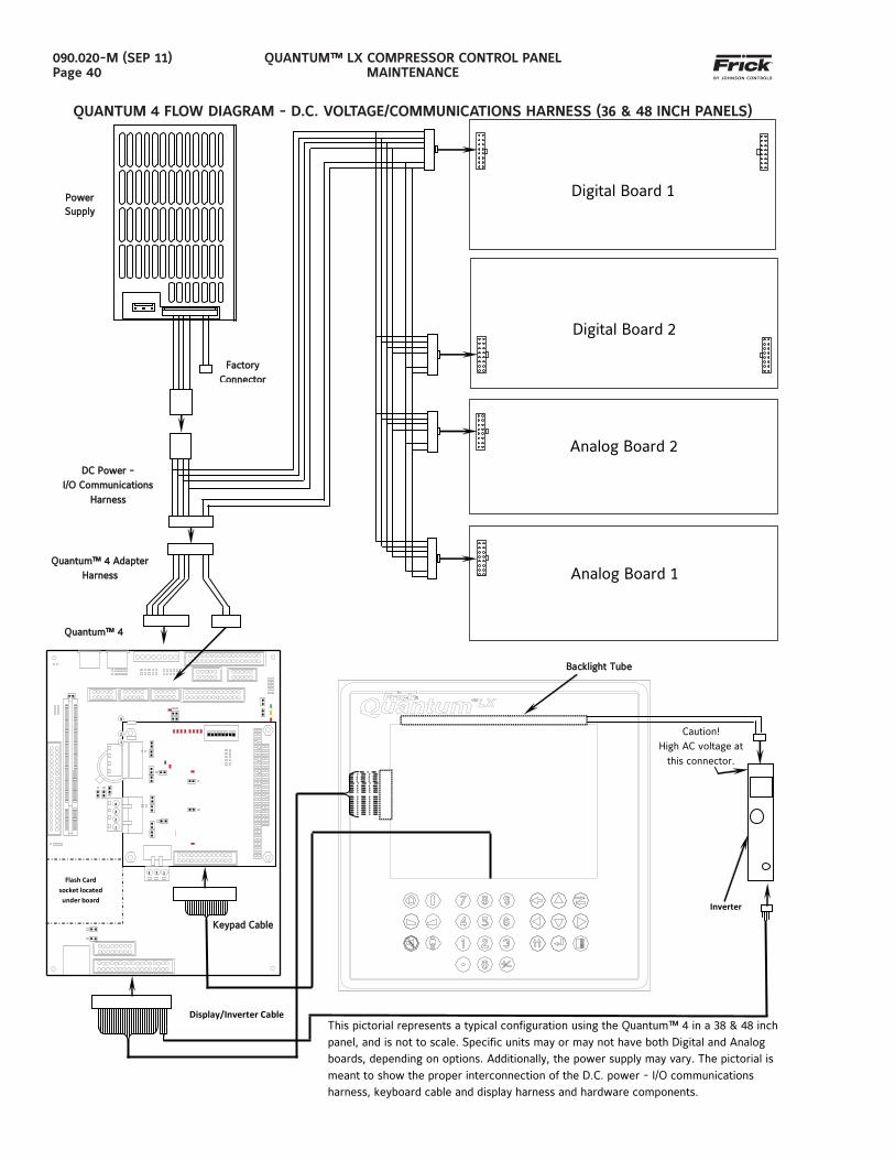
QUANTUM™ LX COMPRESSOR CONTROL PANELMAINTENANCE
090.020-M (SEP 11)Page 40
QUANTUM 4 FLOW DIAGRAM - D.C. VOLTAGE/COMMUNICATIONS HARNESS (36 & 48 INCH PANELS)
Backlight TubeBacklight Tube
Caution! High AC voltage at
this connector
Inverter
This pictorial represents a typical configuration using the Quantum™ 4 in a 38 & 48 inch panel, and is not to scale. Specific units may or may not have both Digital and Analog boards, depending on options. Additionally, the power supply may vary. The pictorial is meant to show the proper interconnection of the D.C. power - I/O communications harness, keyboard cable and display harness and hardware components.
Keypad CableKeypad Cable
Display/Inverter Cable
P
P
Flash Card socket located under board
1
2
3
4
3 2 1
Quantum™ 4 Adapter Quantum™ 4 Adapter HarnessHarness
Quantum™ 4Quantum™ 4
Power Power SupplySupply
Factory Factory ConnectorConnector
DC Power DC Power -- I/O Communications I/O Communications
HarnessHarness
Digital Board 1
Digital Board 2
Analog Board 2
Analog Board 1
1
2
4
Caution! High AC voltage at
this connector.
Inverter
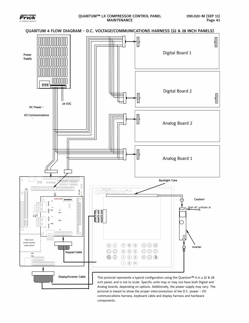
QUANTUM™ LX COMPRESSOR CONTROL PANELMAINTENANCE
090.020-M (SEP 11)Page 41
QUANTUM 4 FLOW DIAGRAM - D.C. VOLTAGE/COMMUNICATIONS HARNESS (22 & 28 INCH PANELS)
This pictorial represents a typical configuration using the Quantum™ 4 in a 22 & 28 inch panel, and is not to scale. Specific units may or may not have both Digital and Analog boards, depending on options. Additionally, the power supply may vary. The pictorial is meant to show the proper interconnection of the D.C. power - I/O communications harness, keyboard cable and display harness and hardware components.
Digital Board 1
Digital Board 2
Analog Board 2
Analog Board 1
Power Power SupplySupply
DC Power DC Power --
I/O Communications I/O Communications
HHarness
24 VDC24 VDC
Connections
Keypad CableKeypad Cable
InverterInverter
Display/Inverter CableDisplay/Inverter Cable
P
P
Flash Card socket located under board
1
2
3
4
3 2 1
1
2
4
3
Caution!Caution!
High AC voltage at
Backlight TubeBacklight Tube
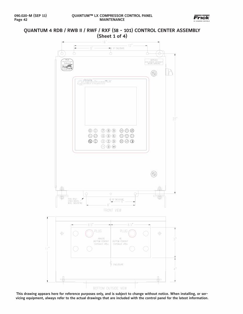
QUANTUM™ LX COMPRESSOR CONTROL PANELMAINTENANCE
090.020-M (SEP 11)Page 42
QUANTUM 4 RDB / RWB II / RWF / RXF (58 - 101) CONTROL CENTER ASSEMBLY(Sheet 1 of 4)
This drawing appears here for reference purposes only, and is subject to change without notice. When installing, or ser-vicing equipment, always refer to the actual drawings that are included with the control panel for the latest information.
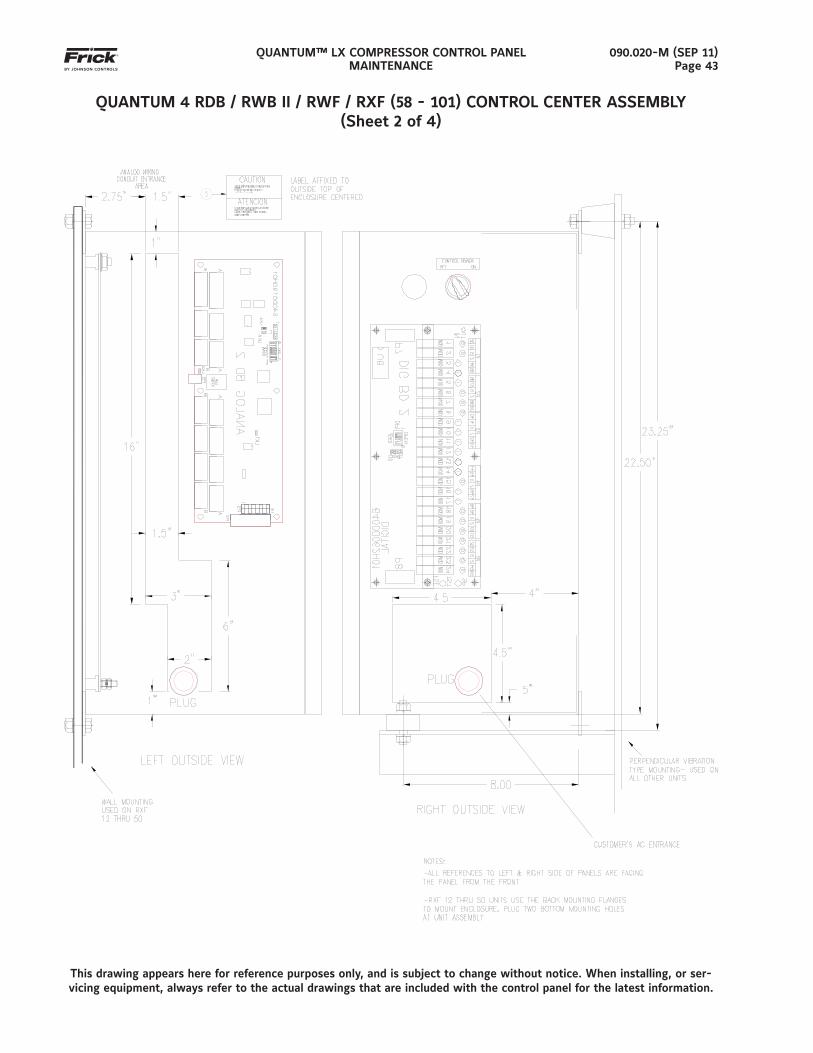
QUANTUM™ LX COMPRESSOR CONTROL PANELMAINTENANCE
090.020-M (SEP 11)Page 43
QUANTUM 4 RDB / RWB II / RWF / RXF (58 - 101) CONTROL CENTER ASSEMBLY(Sheet 2 of 4)
This drawing appears here for reference purposes only, and is subject to change without notice. When installing, or ser-vicing equipment, always refer to the actual drawings that are included with the control panel for the latest information.
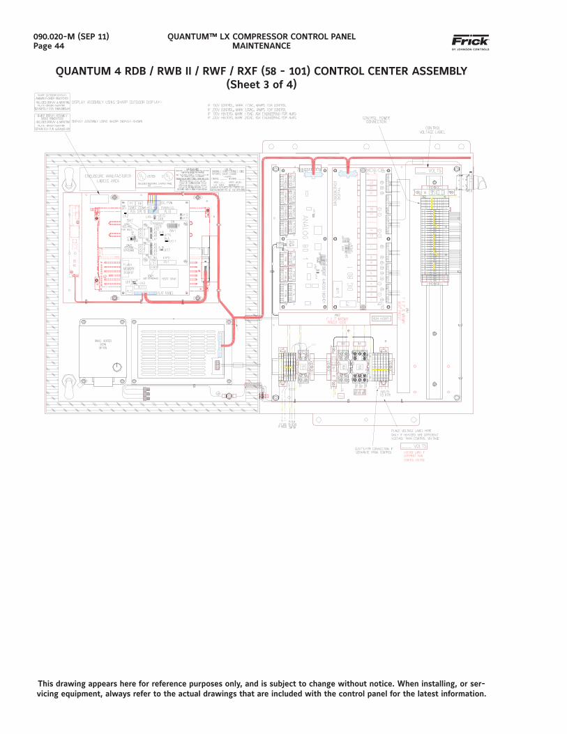
QUANTUM™ LX COMPRESSOR CONTROL PANELMAINTENANCE
090.020-M (SEP 11)Page 44
QUANTUM 4 RDB / RWB II / RWF / RXF (58 - 101) CONTROL CENTER ASSEMBLY(Sheet 3 of 4)
This drawing appears here for reference purposes only, and is subject to change without notice. When installing, or ser-vicing equipment, always refer to the actual drawings that are included with the control panel for the latest information.
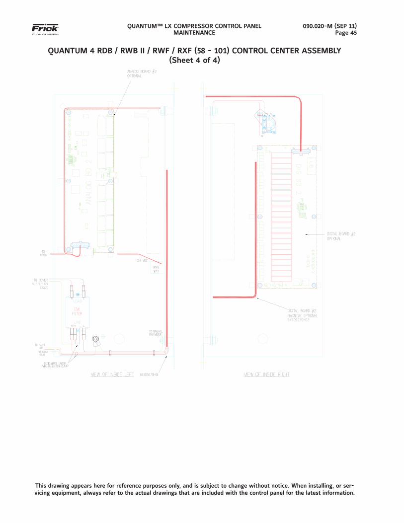
QUANTUM™ LX COMPRESSOR CONTROL PANELMAINTENANCE
090.020-M (SEP 11)Page 45
QUANTUM 4 RDB / RWB II / RWF / RXF (58 - 101) CONTROL CENTER ASSEMBLY(Sheet 4 of 4)
This drawing appears here for reference purposes only, and is subject to change without notice. When installing, or ser-vicing equipment, always refer to the actual drawings that are included with the control panel for the latest information.
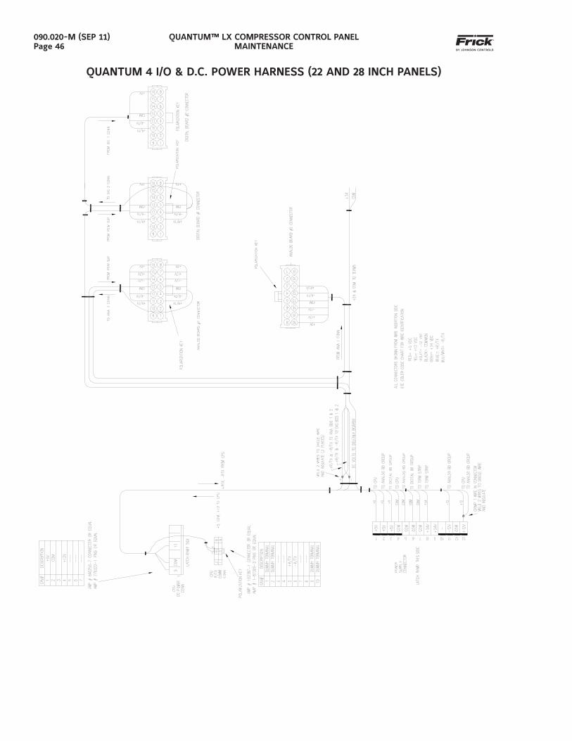
QUANTUM™ LX COMPRESSOR CONTROL PANELMAINTENANCE
090.020-M (SEP 11)Page 46
QUANTUM 4 I/O & D.C. POWER HARNESS (22 AND 28 INCH PANELS)
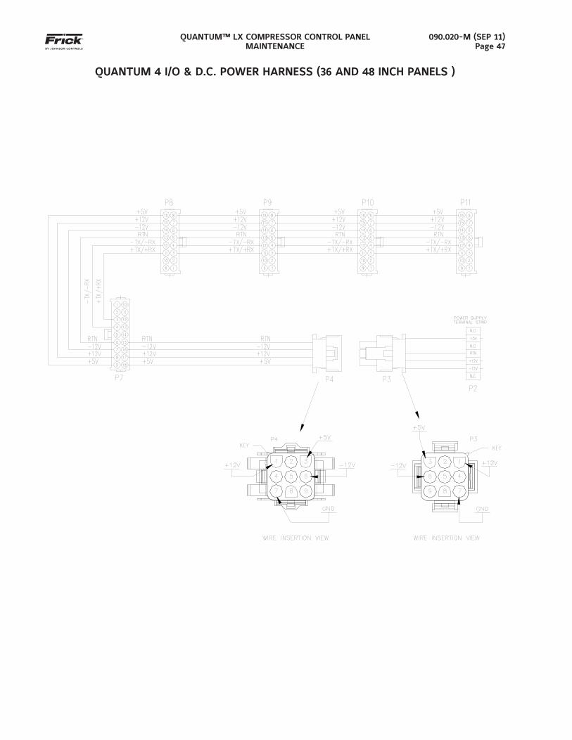
QUANTUM™ LX COMPRESSOR CONTROL PANELMAINTENANCE
090.020-M (SEP 11)Page 47
QUANTUM 4 I/O & D.C. POWER HARNESS (36 AND 48 INCH PANELS )
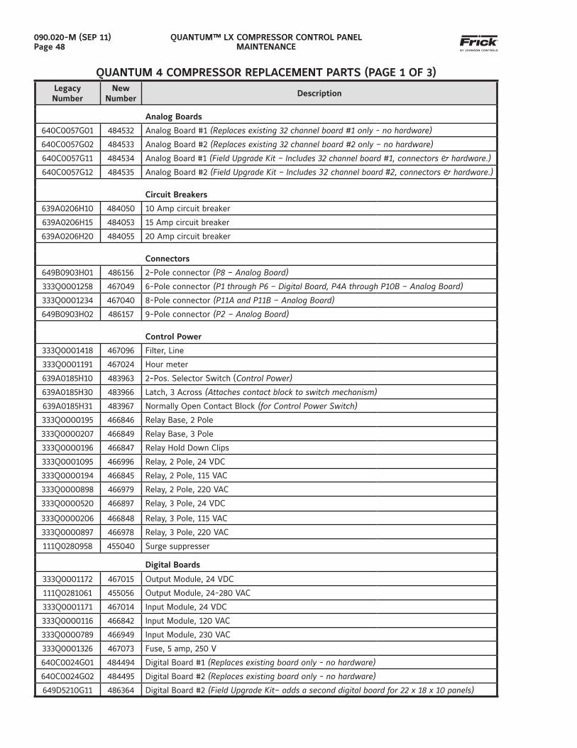
QUANTUM™ LX COMPRESSOR CONTROL PANELMAINTENANCE
090.020-M (SEP 11)Page 48
QUANTUM 4 COMPRESSOR REPLACEMENT PARTS (PAGE 1 OF 3)LegacyNumber
NewNumber
Description
Analog Boards
640C0057G01 484532 Analog Board #1 (Replaces existing 32 channel board #1 only - no hardware)
640C0057G02 484533 Analog Board #2 (Replaces existing 32 channel board #2 only – no hardware)
640C0057G11 484534 Analog Board #1 (Field Upgrade Kit – Includes 32 channel board #1, connectors & hardware.)
640C0057G12 484535 Analog Board #2 (Field Upgrade Kit – Includes 32 channel board #2, connectors & hardware.)
Circuit Breakers
639A0206H10 484050 10 Amp circuit breaker
639A0206H15 484053 15 Amp circuit breaker
639A0206H20 484055 20 Amp circuit breaker
Connectors
649B0903H01 486156 2-Pole connector (P8 – Analog Board)
333Q0001258 467049 6-Pole connector (P1 through P6 – Digital Board, P4A through P10B – Analog Board)
333Q0001234 467040 8-Pole connector (P11A and P11B – Analog Board)
649B0903H02 486157 9-Pole connector (P2 – Analog Board)
Control Power
333Q0001418 467096 Filter, Line
333Q0001191 467024 Hour meter
639A0185H10 483963 2-Pos. Selector Switch (Control Power)
639A0185H30 483966 Latch, 3 Across (Attaches contact block to switch mechanism)
639A0185H31 483967 Normally Open Contact Block (for Control Power Switch)
333Q0000195 466846 Relay Base, 2 Pole
333Q0000207 466849 Relay Base, 3 Pole
333Q0000196 466847 Relay Hold Down Clips
333Q0001095 466996 Relay, 2 Pole, 24 VDC
333Q0000194 466845 Relay, 2 Pole, 115 VAC
333Q0000898 466979 Relay, 2 Pole, 220 VAC
333Q0000520 466897 Relay, 3 Pole, 24 VDC
333Q0000206 466848 Relay, 3 Pole, 115 VAC
333Q0000897 466978 Relay, 3 Pole, 220 VAC
111Q0280958 455040 Surge suppresser
Digital Boards
333Q0001172 467015 Output Module, 24 VDC
111Q0281061 455056 Output Module, 24-280 VAC
333Q0001171 467014 Input Module, 24 VDC
333Q0000116 466842 Input Module, 120 VAC
333Q0000789 466949 Input Module, 230 VAC
333Q0001326 467073 Fuse, 5 amp, 250 V
640C0024G01 484494 Digital Board #1 (Replaces existing board only - no hardware)
640C0024G02 484495 Digital Board #2 (Replaces existing board only - no hardware)
649D5210G11 486364 Digital Board #2 (Field Upgrade Kit– adds a second digital board for 22 x 18 x 10 panels)
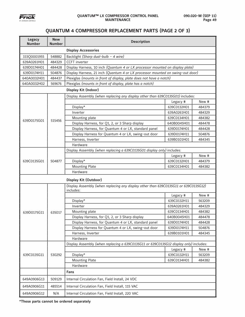
QUANTUM™ LX COMPRESSOR CONTROL PANELMAINTENANCE
090.020-M (SEP 11)Page 49
QUANTUM 4 COMPRESSOR REPLACEMENT PARTS (PAGE 2 OF 3)
*These parts cannot be ordered separately
LegacyNumber
NewNumber
Description
Display Accessories
333Q0001955 548882 Backlight (Sharp dual-bulb – 4 wire)639A0261H01 484329 CCFT inverter
639D0174H01 484428 Display Harness, 10 inch (Quantum 4 or LX processor mounted on display plate)639D0174H11 504876 Display Harness, 21 inch (Quantum 4 or LX processor mounted on swing-out door)640A0032H01 484437 Plexiglas (mounts in front of display, plate does not have a notch)640A0032H02 569676 Plexiglas (mounts in front of display, plate has a notch)
Display Kit (Indoor)
639D0175G01 515456
Display Assembly (when replacing any display other than 639C0135G01) includes:
Legacy # New #
Display* 639C0132H01 484379
Inverter 639A0261H01 484329
Mounting plate 639C0134H01 484382
Display Harness, for Q1, 2, or 3 Sharp display 640B0045H01 484478
Display Harness, for Quantum 4 or LX, standard panel 639D0174H01 484428
Display Harness for Quantum 4 or LX, swing-out door 639D0174H11 504876
Harness, Inverter 639B0101H01 484345
Hardware
639C0135G01 504877
Display Assembly (when replacing a 639C0135G01 display only) includes:
Legacy # New #
Display* 639C0132H01 484379
Mounting Plate 639C0134H01 484382
Hardware
Display Kit (Outdoor)
639D0175G11 635017
Display Assembly (when replacing any display other than 639C0135G11 or 639C0135G12) includes:
Legacy # New #
Display* 639C0132H11 563209
Inverter 639A0261H01 484329
Mounting plate 639C0134H01 484382
Display Harness, for Q1, 2, or 3 Sharp display 640B0045H01 484478
Display Harness, for Quantum 4 or LX, standard panel 639D0174H01 484428
Display Harness for Quantum 4 or LX, swing-out door 639D0174H11 504876
Harness, Inverter 639B0101H01 484345
Hardware
639C0135G11 530292
Display Assembly (when replacing a 639C0135G11 or 639C0135G12 display only) includes:
Legacy # New #
Display* 639C0132H11 563209
Mounting Plate 639C0134H01 484382
Hardware
Fans
649A0906G13 509129 Internal Circulation Fan, Field Install, 24 VDC
649A0906G11 485514 Internal Circulation Fan, Field Install, 115 VAC
649A0906G12 N/A Internal Circulation Fan, Field Install, 220 VAC
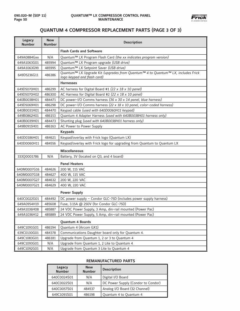
QUANTUM™ LX COMPRESSOR CONTROL PANELMAINTENANCE
090.020-M (SEP 11)Page 50
QUANTUM 4 COMPRESSOR REPLACEMENT PARTS (PAGE 3 OF 3)
LegacyNumber
NewNumber
Description
Flash Cards and Software
649A0884Gxx N/A Quantum™ LX Program Flash Card (the xx indicates program version)649A1063G01 485994 Quantum™ LX Program upgrade (USB drive)649A1063G99 485995 Quantum™ LX Setpoint Saver (USB drive)
649D5236G11 486386Quantum™ LX Upgrade Kit (upgrades from Quantum™ 4 to Quantum™ LX, includes Frick logo keypad and fl ash card)
Harnesses
649D5070H01 486299 AC harness for Digital Board #1 (22 x 18 x 10 panel)649D5070H02 486300 AC Harness for Digital Board #2 (22 x 18 x 10 panel)640B0038H01 484471 DC power-I/O Comms harness (36 x 30 x 14 panel, blue harness)649D5069H01 486298 DC power-I/O Comms harness (22 x 18 x 10 panel, color-coded harness)640B0031H01 484470 Keypad cable (used with 640D0060H11 keypad)649B0862H01 486153 Quantum 4 Adapter Harness (used with 640B0038H01 harness only)640B0039H01 484473 Shunting plug (used with 640B0038H01 harness only)649B0915H01 486163 AC Power to Power Supply
Keypads
640D0186H01 484621 Keypad/overlay with Frick logo (Quantum LX)
640D0060H11 484556 Keypad/overlay with Frick logo for upgrading from Quantum to Quantum LX
Miscellaneous
333Q0001786 N/A Battery, 3V (located on Q3, and 4 board)
Panel Heaters
640M0007G16 484626 200 W, 115 VAC
640M0007G18 484627 400 W, 115 VAC
640M0007G27 484632 200 W, 220 VAC
640M0007G21 484629 400 W, 220 VAC
Power Supply
640C0022G01 484492 DC power supply – Condor GLC-75D (includes power supply harness)
649A0954H19 485608 Fuse, 3.15A @ 250V (for Condor GLC-75D)
649A1036H08 485887 24 VDC Power Supply, 3 Amp, din-rail mounted (Power Pac)
649A1036H12 485889 24 VDC Power Supply, 5 Amp, din-rail mounted (Power Pac)
Quantum 4 Boards
649C1091G01 486194 Quantum 4 (Arcom GX1)
639C0130G01 484378 Communications Daughter board only for Quantum 4.
649C1083G01 486181 Upgrade from Quantum 1, 2 or 3 to Quantum 4
649C1093G01 N/A Upgrade from Quantum 1, 2 Lite to Quantum 4
649C1092G01 N/A Upgrade from Quantum 3 Lite to Quantum 4
REMANUFACTURED PARTS
LegacyNumber
NewNumber
Description
640C0024S01 N/A Digital I/O Board
640C0022S01 N/A DC Power Supply (Condor to Condor)
640C0057S01 484537 Analog I/O Board (32 Channel)
649C1091S01 486198 Quantum 4 to Quantum 4
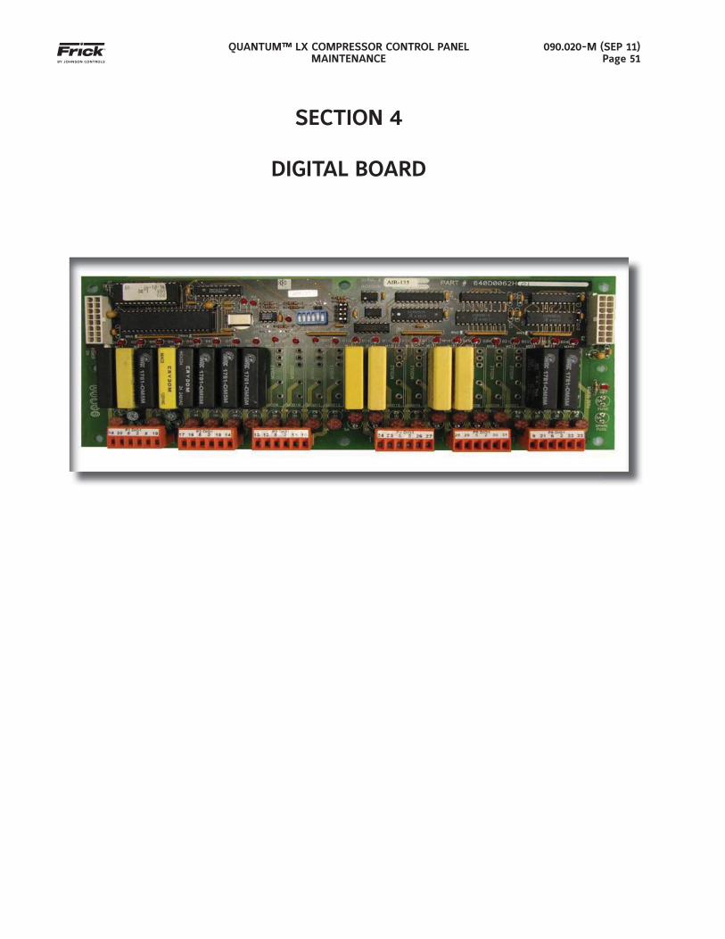
QUANTUM™ LX COMPRESSOR CONTROL PANELMAINTENANCE
090.020-M (SEP 11)Page 51
SECTION 4
DIGITAL BOARD
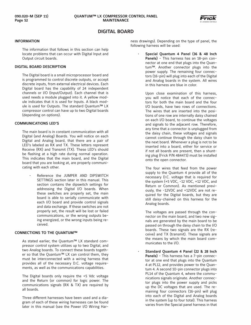
QUANTUM™ LX COMPRESSOR CONTROL PANELMAINTENANCE
090.020-M (SEP 11)Page 52
DIGITAL BOARD
INFORMATION
The information that follows in this section can help locate problems that can occur with Digital Input and Output circuit boards.
DIGITAL BOARD DESCRIPTION
The Digital board is a small microprocessor board and is programmed to control discrete outputs, or accept discrete inputs, from external electrical devices. Each Digital board has the capability of 24 independent channels or I/O (Input/Output). Each channel that is used needs a module plugged into it. A yellow mod-ule indicates that it is used for Inputs. A black mod-ule is used for Outputs. The standard Quantum™ LX compressor control can have up to two Digital boards (depending on options).
COMMUNICATIONS LED'S
The main board is in constant communication with all Digital (and Analog) Boards. You will notice on each Digital and Analog board, that there are a pair of LED's labeled as RX and TX. These letters represent Receive (RX) and Transmit (TX). These LED's should be fl ashing at a high rate during normal operation. This indicates that the main board, and the Digital board that you are looking at, are properly communi-cating with each other.
• Reference the JUMPER AND DIPSWITCH SETTINGS section later in this manual. This section contains the dipswitch settings for addressing the Digital I/O boards. When these switches are properly set, the main board is able to serially communicate with each I/O board and provide control signals and data exchange. If these switches are not properly set, the result will be lost or failed communications, or the wrong outputs be-ing energized, or the wrong inputs being re-ceived.
CONNECTIONS TO THE QUANTUM™
As stated earlier, the Quantum™ LX standard com-pressor control system utilizes up to two Digital, and two Analog boards. To connect these boards togeth-er so that the Quantum™ LX can control them, they must be interconnected with a wiring harness that provides all of the necessary D.C. voltage require-ments, as well as the communications capabilities.
The Digital boards only require the +5 Vdc voltage and the Return (or common) for logic power. The communications signals (RX & TX) are required by all boards.
Three different harnesses have been used and a dia-gram of each of these wiring harnesses can be found later in this manual (see the Power I/O Wiring Har-
ness drawings). Depending on the type of panel, the following harness will be used:
• Special Quantum 4 Panel (36 & 48 Inch Panels) - This harness has an 18-pin con-nector at one end that plugs into the Quan-tum™. Another connector plugs into the power supply. The remaining four connec-tors (16-pin) will plug into each of the Digital and Analog boards in the system. All wires in this harness are blue in color.
Upon close examination of this harness, you will notice that each of the connec-tors for both the main board and the four I/O boards, have two rows of connections. The wires that are inserted into the posi-tions of one row are internally daisy chained on each I/O board, to continue the voltages and signals to the adjacent row. Therefore, any time that a connector is unplugged from the daisy chain, these voltages and signals cannot continue through the daisy chain to the next board. Whenever a plug is not to be inserted into a board, either for service or if not all boards are present, then a shunt-ing plug (Frick P/N 484473) must be installed onto the open connector.
The four wires that feed from the power supply to the Quantum 4 provide all of the necessary D.C. voltage that is required for the system (+5 VDC, -12 VDC, +12 VDC, and Return or Common). As mentioned previ-ously, the -12VDC and +12VDC are not re-quired for the Digital boards, but they are still daisy-chained on this harness for the Analog boards.
The voltages are passed through the con-nector on the main board, and two new sig-nals are generated by the main board to be passed on through the daisy chain to the I/O boards. These two signals are the RX (re-ceive) and TX (transmit). These signals are the means by which the main board com-municates to the I/O.
• Standard Quantum 4 Panel (22 & 28 Inch Panels) - This harness has a 7-pin connec-tor at one end that plugs into the Quantum 4 at PL12, and provides power to the Quan-tum 4. A second 10-pin connector plugs into PL14 of the Quantum 4, where the commu-nications signals originate. Another connec-tor plugs into the power supply and picks up the DC voltages that are used. The re-maining four connectors (16-pin) will plug into each of the Digital and Analog boards in the system (up to four total). This harness varies from the Special panel harness in that
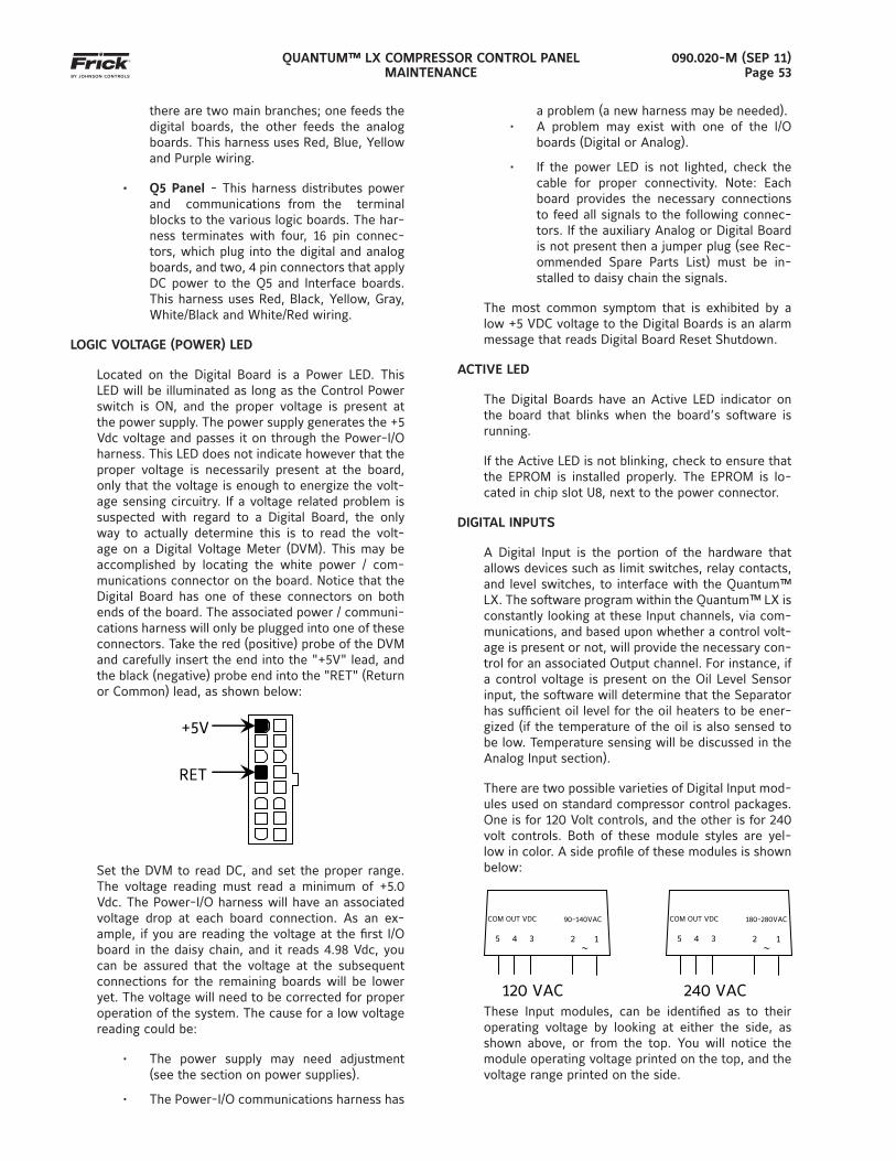
QUANTUM™ LX COMPRESSOR CONTROL PANELMAINTENANCE
090.020-M (SEP 11)Page 53
there are two main branches; one feeds the digital boards, the other feeds the analog boards. This harness uses Red, Blue, Yellow and Purple wiring.
• Q5 Panel - This harness distributes power and communications from the terminal blocks to the various logic boards. The har-ness terminates with four, 16 pin connec-tors, which plug into the digital and analog boards, and two, 4 pin connectors that apply DC power to the Q5 and Interface boards. This harness uses Red, Black, Yellow, Gray, White/Black and White/Red wiring.
LOGIC VOLTAGE (POWER) LED
Located on the Digital Board is a Power LED. This LED will be illuminated as long as the Control Power switch is ON, and the proper voltage is present at the power supply. The power supply generates the +5 Vdc voltage and passes it on through the Power-I/O harness. This LED does not indicate however that the proper voltage is necessarily present at the board, only that the voltage is enough to energize the volt-age sensing circuitry. If a voltage related problem is suspected with regard to a Digital Board, the only way to actually determine this is to read the volt-age on a Digital Voltage Meter (DVM). This may be accomplished by locating the white power / com-munications connector on the board. Notice that the Digital Board has one of these connectors on both ends of the board. The associated power / communi-cations harness will only be plugged into one of these connectors. Take the red (positive) probe of the DVM and carefully insert the end into the "+5V" lead, and the black (negative) probe end into the "RET" (Return or Common) lead, as shown below:
+5V
RET
Set the DVM to read DC, and set the proper range. The voltage reading must read a minimum of +5.0 Vdc. The Power-I/O harness will have an associated voltage drop at each board connection. As an ex-ample, if you are reading the voltage at the fi rst I/O board in the daisy chain, and it reads 4.98 Vdc, you can be assured that the voltage at the subsequent connections for the remaining boards will be lower yet. The voltage will need to be corrected for proper operation of the system. The cause for a low voltage reading could be:
• The power supply may need adjustment (see the section on power supplies).
• The Power-I/O communications harness has
a problem (a new harness may be needed).• A problem may exist with one of the I/O
boards (Digital or Analog).
• If the power LED is not lighted, check the cable for proper connectivity. Note: Each board provides the necessary connections to feed all signals to the following connec-tors. If the auxiliary Analog or Digital Board is not present then a jumper plug (see Rec-ommended Spare Parts List) must be in-stalled to daisy chain the signals.
The most common symptom that is exhibited by a low +5 VDC voltage to the Digital Boards is an alarm message that reads Digital Board Reset Shutdown.
ACTIVE LED
The Digital Boards have an Active LED indicator on the board that blinks when the board’s software is running.
If the Active LED is not blinking, check to ensure that the EPROM is installed properly. The EPROM is lo-cated in chip slot U8, next to the power connector.
DIGITAL INPUTS
A Digital Input is the portion of the hardware that allows devices such as limit switches, relay contacts, and level switches, to interface with the Quantum™ LX. The software program within the Quantum™ LX is constantly looking at these Input channels, via com-munications, and based upon whether a control volt-age is present or not, will provide the necessary con-trol for an associated Output channel. For instance, if a control voltage is present on the Oil Level Sensor input, the software will determine that the Separator has suffi cient oil level for the oil heaters to be ener-gized (if the temperature of the oil is also sensed to be low. Temperature sensing will be discussed in the Analog Input section).
There are two possible varieties of Digital Input mod-ules used on standard compressor control packages. One is for 120 Volt controls, and the other is for 240 volt controls. Both of these module styles are yel-low in color. A side profi le of these modules is shown below:
5 4 3
COM OUT VDC
2
1
90-140VAC
120 VAC
5 4 3
COM OUT VDC
2
1
180-280VAC
240 VAC These Input modules, can be identifi ed as to their operating voltage by looking at either the side, as shown above, or from the top. You will notice the module operating voltage printed on the top, and the voltage range printed on the side.
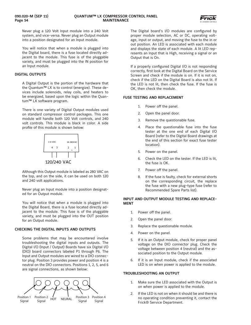
QUANTUM™ LX COMPRESSOR CONTROL PANELMAINTENANCE
090.020-M (SEP 11)Page 54
Never plug a 120 Volt Input module into a 240 Volt system, and vice-versa. Never plug an Output module into a position designated for an Input module.
You will notice that when a module is plugged into the Digital board, there is a fuse located directly ad-jacent to the module. This fuse is of the pluggable variety, and must be plugged into the IN position for an Input module.
DIGITAL OUTPUTS
A Digital Output is the portion of the hardware that the Quantum™ LX is to control (energize). These de-vices include solenoids, relay coils, and heaters to be energized, based upon the logic within the Quan-tum™ LX software program.
There is one variety of Digital Output modules used on standard compressor control packages. This one module will handle both 120 Volt controls, and 240 volt controls. This module is black in color. A side profi le of this module is shown below:
4 3
3-8 VDC
2
1
3A 280VAC
120/240 VAC
Although this Output module is labeled as 280 VAC on the top, and on the side, it can be used on both 120 and 240 volt applications.
Never plug an Input module into a position designat-ed for an Output module.
You will notice that when a module is plugged into the Digital Board, there is a fuse located directly ad-jacent to the module. This fuse is of the pluggable variety, and must be plugged into the OUT position for an Output module.
CHECKING THE DIGITAL INPUTS AND OUTPUTS
Some problems that may be encountered involve troubleshooting the digital inputs and outputs. The Digital I/O (Input / Output) Boards have six Digital I/O (DIO) board connectors labeled P1 through P6. The Input and Output modules are wired to a DIO connec-tor plug. Position 3 provides power and position 4 is a neutral on the DIO connectors. Positions 1, 2, 5, and 6 are signal connections, as shown below:
Position 1Signal
Position 2Signal
HOT NEURALPosition 3
SignalPosition 4
Signal
The Digital board’s I/O modules are confi gured by proper module selection, AC or DC, operating volt-age, input or output, and moving the fuse to the in or out position. An LED is associated with each module and displays the state of each module. A lit LED rep-resents an Input that is High, receiving a signal or an Output that is On.
If a properly confi gured Digital I/O is not responding correctly, fi rst look at the Digital Board on the Service Screen and check if the module is on. If it is not on, check if the LED on the Digital Board is also not lit. If the LED is not lit, then check the fuse. If the fuse is OK, then check the module.
FUSE TESTING AND REPLACEMENT
1. Power off the panel.
2. Open the panel door.
3. Remove the questionable fuse.
4. Place the questionable fuse into the fuse tester at the one end of each Digital I/O Board (refer to the Digital Board drawings at the end of this section for exact fuse tester location).
5. Power on the panel.
6. Check the LED on the tester. If the LED is lit, the fuse is OK.
7. Power off the panel.
8. If the fuse is faulty, check for external shorts on the corresponding circuit, the replace the fuse with a new plug-type fuse (refer to Recommended Spare Parts list).
INPUT AND OUTPUT MODULE TESTING AND REPLACE-MENT
1. Power off the panel.
2. Open the panel door.
3. Replace the questionable module.
4. Power on the panel.
5. If it is an Output module, check for proper panel voltage on the DIO connector plug. Check the voltage between position 4 (neutral) and the as-sociated position to the Output module.
6. If it is an Input module, check if the associated LED is on when power is applied to the module.
TROUBLESHOOTING AN OUTPUT
1. Make sure the LED associated with the Output is on when power is applied to the module.
2. If the LED is not on when it should be and there is no operating condition preventing it, contact the Frick® Service Department.
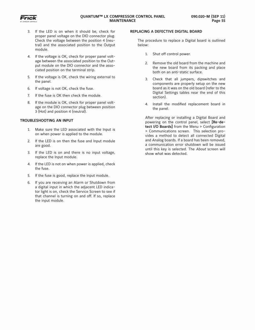
QUANTUM™ LX COMPRESSOR CONTROL PANELMAINTENANCE
090.020-M (SEP 11)Page 55
3. If the LED is on when it should be, check for proper panel voltage on the DIO connector plug. Check the voltage between the position 4 (neu-tral) and the associated position to the Output module.
4. If the voltage is OK, check for proper panel volt-age between the associated position to the Out-put module on the DIO connector and the asso-ciated position on the terminal strip.
5. If the voltage is OK, check the wiring external to the panel.
6. If voltage is not OK, check the fuse.
7. If the fuse is OK then check the module.
8. If the module is OK, check for proper panel volt-age on the DIO connector plug between position 3 (Hot) and position 4 (neutral).
TROUBLESHOOTING AN INPUT
1. Make sure the LED associated with the Input is on when power is applied to the module.
2. If the LED is on then the fuse and Input module are good.
3. If the LED is on and there is no input voltage, replace the Input module.
4. If the LED is not on when power is applied, check the fuse.
5. If the fuse is good, replace the Input module.
6. If you are receiving an Alarm or Shutdown from a digital input in which the adjacent LED indica-tor light is on, check the Service Screen to see if that channel is turning on and off. If so, replace the input module.
REPLACING A DEFECTIVE DIGITAL BOARD
The procedure to replace a Digital board is outlined below:
1. Shut off control power.
2. Remove the old board from the machine and the new board from its packing and place both on an anti-static surface.
3. Check that all jumpers, dipswitches and components are properly setup on the new board as it was on the old board (refer to the Digital Settings tables near the end of this section).
4. Install the modifi ed replacement board in the panel.
After replacing or installing a Digital Board and powering on the control panel, select [Re-de-tect I/O Boards] from the Menu > Confi guration > Communications screen. This selection pro-vides a method to detect all connected Digital and Analog boards. If a board has been removed, a communication error shutdown will be issued until this key is selected. The About screen will show what was detected.
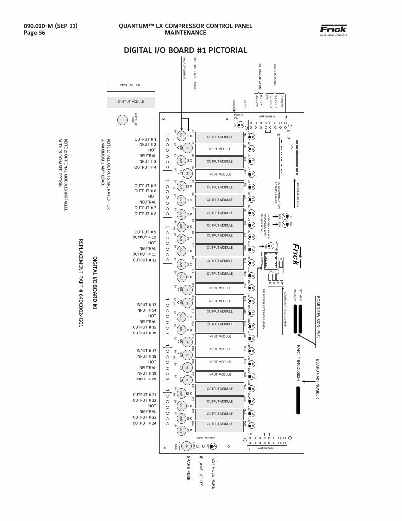
QUANTUM™ LX COMPRESSOR CONTROL PANELMAINTENANCE
090.020-M (SEP 11)Page 56
DIGITAL I/O BOARD #1 PICTORIAL
+5 VO
LTS
+12 VO
LTS
-12 VO
LTS
GN
D
-RX
/ -TX
+RX
/ +TX
BO
AR
D D
C PO
WER
I/O C
OM
MU
NIC
AT
ION
S
+5 DC
U8 P7
DIG
ITA
L I/O B
OA
RD
#1
DIG
ITA
L I/O B
OA
RD
#1
REPLA
CEM
ENT PA
RT #
640C0024G
01
NO
TE 1:
NO
TE 1: A
LL OU
TPU
TS A
RE R
ATED
FOR
A M
AX
IMU
M 2 A
MP LO
AD
.
NO
TE 2:
NO
TE 2: O
PTIO
NA
L MO
DU
LES IN
STA
LLED
WIT
H P
UR
CH
ASED
OPTIO
N
TEST FUSE H
ERE.
IF LAMP LIG
HTS
SPARE FU
SE
5A OU
T
F20
M20 INPUT MODULE
D20
IN
IN
1 P
5 5A
OU
T
F19
M19 INPUT MODULE
D19
IN
5A OU
T
F18
M18 INPUT MODULE
D18
IN
5A OU
T
F17
M17 INPUT MODULE
D17
IN
1 P4
5A OU
T
F13
M13 INPUT MODULE
D13
IN
5A O
UT
IN
F12
M12 OUTPUT MODULE
D12
5A O
UT
IN
F11
M11 OUTPUT MODULE
D11
1 P3
5A O
UT
IN
F10
M10 OUTPUT MODULE
D10
5A O
UT
IN
F9 M9 OUTPUT MODULE
D9
5A O
UT
IN
F8 M8 OUTPUT MODULE
D8
5A O
UT
IN
F7 M7 OUTPUT MODULE
D7
1 P
2 5A
OU
T
IN
F6 M6 OUTPUT MODULE
D6
5A O
UT
IN
F5 M5 OUTPUT MODULE
D5
5A OU
T
F4 M4 INPUT MODULE
D4
IN
5A O
UT
IN
F3 M3 OUTPUT MODULE
D3
1 P1
5A OU
T
F2 M2 INPUT MODULE
D2
IN
INST
ALLED
FU
SE
OUTPUT MODULE
POWER ON
FUSE PO
SITION
DET
ERM
INES
INPU
T OR
OU
TPU
T
5A O
UT
F1 M1 OUTPUT MODULE
D1
D29
1 AMP794068-1
PR
OG
RA
M E
PR
OM
DIO
19200I/O
CO
MM
UN
ICA
TION
A
CTIV
ITY LA
MP
S D
25 TX D
26 RX
D28
ACTIVE
MIC
RO
PR
OC
ES
SO
R
WA
TCH
DO
G LA
MP
(B
LINK
SIF
OK
)
P8
5A
FUSE
SP
AR
E
FUSE
D27
FUSE TESTER
1 AMP794068-1
1 P6
5A O
UT
IN
F24
M24 OUTPUT MODULE
D24
1
OP
EN
Frick *
J5
DP1
J7 J8 J9 J10
5A O
UT
IN
F16
M16 OUTPUT MODULE
D16
5A O
UT
IN
F15
M15 OUTPUT MODULE
D15
5A OU
T
F14
M14 INPUT MODULE
D14
IN
SERIA
L #
REVISIO
N
DIPSW
ITCH
SETTING
S SIG
NIFY
CO
MM
UN
ICA
TIO
NS JU
MPER
S
5A O
UT
IN
F23
M23 OUTPUT MODULE
D23
5A O
UT
IN
F22
M22 OUTPUT MODULE
D22
5A O
UT
IN
F21
M21 OUTPUT MODULE
D21
PART # 640D
0062H
BO
AR
D R
EVIS
ION
LEVEL
BO
AR
D P
ART N
UM
BER
INPUT MODULE
OUTPUT # 1 INPUT # 2
HOT NEUTRAL INPUT # 3
OUTPUT # 4
OUTPUT # 5 OUTPUT # 6
HOT NEUTRAL
OUTPUT # 7
OUTPUT # 8
OUTPUT # 9 OUTPUT # 10
HOT NEUTRAL
OUTPUT # 11
OUTPUT # 12
INPUT # 13 INPUT # 14
HOT NEUTRAL
OUTPUT # 15
OUTPUT # 16
INPUT # 17 INPUT # 18
HOT NEUTRAL
INPUT # 19
INPUT # 20
OUTPUT # 21 OUTPUT # 22
HOT NEUTRAL
OUTPUT # 23
OUTPUT # 24
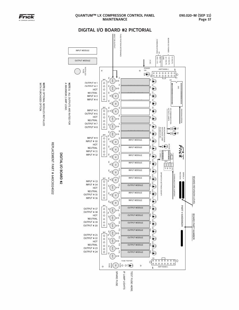
QUANTUM™ LX COMPRESSOR CONTROL PANELMAINTENANCE
090.020-M (SEP 11)Page 57
DIGITAL I/O BOARD #2 PICTORIAL
5A
F20
M20 OUTPUT MODULE
D20
BOAR
D R
EVISIO
N LEVEL
BOAR
D PA
RT N
UM
BER
1 P
5 5A
F19
M19 OUTPUT MODULE
D19
5A
F18
M18 OUTPUT MODULE
D18
5A
F17
M17 INPUT MODULE
D17
1 P4
5A
F13
M13 INPUT MODULE
D13
5A
F12
M12 INPUT MODULE
D12
5A
F11
M11 INPUT MODULE
D11
1 P3
5A
F10
M10 INPUT MODULE
D10
5A
F9 M9 INPUT MODULE
D9
5A
F8 M8
OUTPUT MODULE
D8
5A
F7 M7
OUTPUT MODULE
D7
P8
5A
FUSE
SP
AR
E
FUSE
D27
FUSE TESTER
1 AMP794068-1
1 P6
5A
F24
M24 OUTPUT MODULE
D24
1
OP
EN
Frick *
J5
DP1
J7 J8 J9 J10
SERIA
L #
REVISIO
N
5A
F14
M14 INPUT MODULE
D14
DIPSW
ITCH
SETTING
S SIG
NIFY
CO
MM
UN
ICA
TION
S JU
MP
ER
S
5A
F23
M23 OUTPUT MODULE
D23
5A
F22
M22 OUTPUT MODULE
D22
5A
F21
M21 OUTPUT MODULE
D21
PART # 640D
0062H
5A
F16
M16 INPUT MODULE
D16
5A
F15
M15 OUTPUT MODULE
D15
INPUT MODULE
+5 VO
LTS
+12 VO
LTS
-12 VO
LTS
GN
D
-RX
/ -TX
+RX
/ +TX
BO
AR
D D
C P
OW
ER
I/O
CO
MM
UN
ICA
TION
S
+5 DC
U8 P7
DIG
ITA
L I/O B
OA
RD
#2
DIG
ITA
L I/O B
OA
RD
#2
REPLA
CEM
ENT PA
RT #
640C0024G
02
NO
TE 1:
NO
TE 1: A
LL OU
TPU
TS A
RE R
ATED
FOR
A M
AX
IMU
M 2 A
MP LO
AD
.
NO
TE 2:
NO
TE 2: O
PTIO
NA
L MO
DU
LES IN
STA
LLED
WIT
H P
UR
CH
ASED
OPTIO
N
TEST FUSE H
ERE.
IF LAMP LIG
HTS
SPARE FU
SE
OUTPUT # 1OUTPUT # 2
HOTNEUTRALINPUT # 3
INPUT # 4
INPUT # 5 OUTPUT # 6
HOT NEUTRAL
OUTPUT # 7
OUTPUT # 8
INPUT # 9 INPUT # 10
HOT NEUTRAL
INPUT # 11
INPUT # 12
INPUT # 13 INPUT # 14
HOT NEUTRAL
OUTPUT # 15
INPUT # 16
OUTPUT # 17 OUTPUT # 18
HOT NEUTRAL
OUTPUT # 19
OUTPUT # 20
OUTPUT # 21 OUTPUT # 22
HOT NEUTRAL
OUTPUT # 23
OUTPUT # 24
PR
OG
RA
M E
PR
OM
DIO
19200I/O
CO
MM
UN
ICA
TION
A
CTIV
ITY LA
MP
S D
25 TX D
26 RX
D28
ACTIVE
MIC
RO
PR
OC
ES
SO
R
WA
TCH
DO
G LA
MP
(B
LINK
SIF
OK
)
1 AMP794068-1
INS
TALLE
D
FUSE
OUTPUT MODULE
POWER ON
FUSE PO
SITION
DE
TER
MIN
ES
INPU
T OR
OU
TPUT
5A
F1 M1
OUTPUT MODULED
1
D29
1 P
2
1 P1
5A
F2 M2
OUTPUT MODULE
D2
5A
F3 M3
INPUT MODULE
D3
5A
F5 M5
INPUT MODULE
D5
5A
F4 M4
INPUT MODULE
D4
5A
F6 M6
OUTPUT MODULE
D6
OU
T
IN
OU
T
IN
OU
T
IN
OU
T
IN
IN
OU
T
IN
OU
T O
UT
IN
OU
T
IN
OU
T
IN
OU
T
IN
OU
T
IN
OU
T
IN
OU
T
IN
OU
T
IN
OU
T
IN
OU
T
IN
OU
T
IN
OU
T
IN
OU
T
IN
OU
T
IN
OU
T
IN
OU
T
IN
OU
T
IN
OU
T
IN
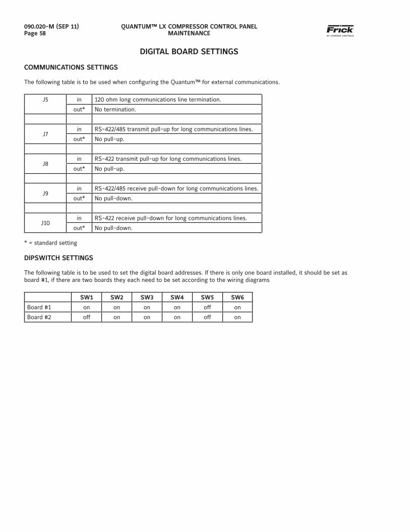
QUANTUM™ LX COMPRESSOR CONTROL PANELMAINTENANCE
090.020-M (SEP 11)Page 58
DIGITAL BOARD SETTINGS
COMMUNICATIONS SETTINGS
The following table is to be used when confi guring the Quantum™ for external communications.
J5 in 120 ohm long communications line termination.
out* No termination.
J7in RS-422/485 transmit pull-up for long communications lines.
out* No pull-up.
J8in RS-422 transmit pull-up for long communications lines.
out* No pull-up.
J9in RS-422/485 receive pull-down for long communications lines.
out* No pull-down.
J10in RS-422 receive pull-down for long communications lines.
out* No pull-down. * = standard setting
DIPSWITCH SETTINGS
The following table is to be used to set the digital board addresses. If there is only one board installed, it should be set as board #1, if there are two boards they each need to be set according to the wiring diagrams
SW1 SW2 SW3 SW4 SW5 SW6
Board #1 on on on on off on
Board #2 off on on on off on
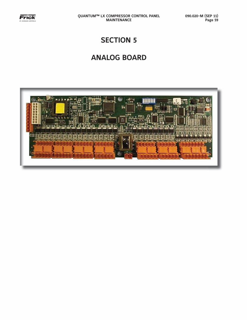
QUANTUM™ LX COMPRESSOR CONTROL PANELMAINTENANCE
090.020-M (SEP 11)Page 59
SECTION 5
ANALOG BOARD
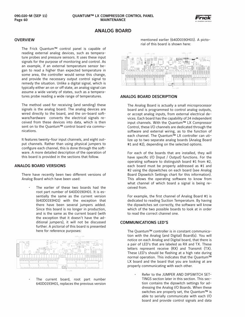
QUANTUM™ LX COMPRESSOR CONTROL PANELMAINTENANCE
090.020-M (SEP 11)Page 60
ANALOG BOARD
OVERVIEW
The Frick Quantum™ control panel is capable of reading external analog devices, such as tempera-ture probes and pressure sensors. It uses these input signals for the purpose of monitoring and control. As an example, if an external temperature sensor be-gan to read a higher than expected temperature in some area, the controller would sense this change, and provide the necessary output control signal to remedy the situation. Unlike a digital signal, which is typically either an on or off state, an analog signal can assume a wide variety of states, such as a tempera-tures probe reading a wide range of temperatures.
The method used for receiving (and sending) these signals is the analog board. The analog devices are wired directly to the board, and the on-board soft-ware/hardware converts the electrical signals re-ceived from these devices into data, which is then sent on to the Quantum™ control board via commu-nications.
It features twenty-four input channels, and eight out-put channels. Rather than using physical jumpers to confi gure each channel, this is done through the soft-ware. A more detailed description of the operation of this board is provided in the sections that follow.
ANALOG BOARD VERSIONS
There have recently been two different versions of Analog Board which have been used:
• The earlier of these two boards had the root part number of 640D0190H01. It is es-sentially the same as the current version (640D0193H01) with the exception that there have been several jumpers added. Since this board is no longer in production, and is the same as the current board (with the exception that it doesn’t have the ad-ditional jumpers), it will not be discussed further. A pictorial of this board is presented here for reference purposes:
• The current board, root part number 640D0193H01, replaces the previous version
mentioned earlier (640D0190H01). A picto-rial of this board is shown here:
ANALOG BOARD DESCRIPTION
The Analog Board is actually a small microprocessor board and is programmed to control analog outputs, or accept analog inputs, from external electrical de-vices. Each board has the capability of 24 independent input channels. With the Quantum™ LX Compressor Control, these I/O channels are dedicated through the software and external wiring, as to the function of each channel. The Quantum™ LX controller can uti-lize up to two separate analog boards (Analog Board #1 and #2), depending on the selected options.
For each of the boards that are installed, they will have specifi c I/O (Input / Output) functions. For the operating software to distinguish board #1 from #2, each board must be properly addressed as #1 and #2 using the dipswitches on each board (see Analog Board Dipswitch Settings chart for this information). This allows the operating software to know from what channel of which board a signal is being re-ceived from.
For example, the fi rst channel of Analog Board #1 is dedicated to reading Suction Temperature. By having the dipswitches set correctly, the software will know which of the two possible boards to look at in order to read the correct channel one.
COMMUNICATIONS LED'S
The Quantum™ controller is in constant communica-tion with the Analog (and Digital) Board(s). You will notice on each Analog and Digital board, that there is a pair of LED's that are labeled as RX and TX. These letters represent receive (RX) and Transmit (TX). These LED's should be fl ashing at a high rate during normal operation. This indicates that the Quantum™ LX board and the board that you are looking at are properly communicating with each other.
• Refer to the JUMPER AND DIPSWITCH SET-TINGS section later in this section. This sec-tion contains the dipswitch settings for ad-dressing the Analog I/O Boards. When these switches are properly set, the Quantum™ is able to serially communicate with each I/O board and provide control signals and data
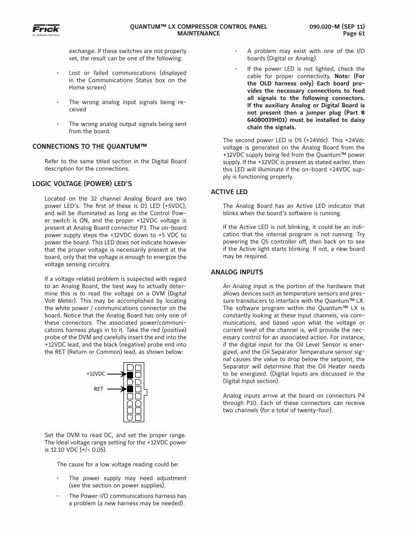
QUANTUM™ LX COMPRESSOR CONTROL PANELMAINTENANCE
090.020-M (SEP 11)Page 61
exchange. If these switches are not properly set, the result can be one of the following:
• Lost or failed communications (displayed in the Communications Status box on the Home screen)
• The wrong analog input signals being re-ceived
• The wrong analog output signals being sent from the board.
CONNECTIONS TO THE QUANTUM™
Refer to the same titled section in the Digital Board description for the connections.
LOGIC VOLTAGE (POWER) LED’S
Located on the 32 channel Analog Board are two power LED’s. The fi rst of these is D1 LED (+5VDC), and will be illuminated as long as the Control Pow-er switch is ON, and the proper +12VDC voltage is present at Analog Board connector P3. The on-board power supply steps the +12VDC down to +5 VDC to power the board. This LED does not indicate however that the proper voltage is necessarily present at the board, only that the voltage is enough to energize the voltage sensing circuitry.
If a voltage related problem is suspected with regard to an Analog Board, the best way to actually deter-mine this is to read the voltage on a DVM (Digital Volt Meter). This may be accomplished by locating the white power / communications connector on the board. Notice that the Analog Board has only one of these connectors. The associated power/communi-cations harness plugs in to it. Take the red (positive) probe of the DVM and carefully insert the end into the +12VDC lead, and the black (negative) probe end into the RET (Return or Common) lead, as shown below:
+12VDC
RET
Set the DVM to read DC, and set the proper range. The Ideal voltage range setting for the +12VDC power is 12.10 VDC (+/- 0.05).
The cause for a low voltage reading could be:
• The power supply may need adjustment (see the section on power supplies).
• The Power-I/O communications harness has a problem (a new harness may be needed).
• A problem may exist with one of the I/O boards (Digital or Analog).
• If the power LED is not lighted, check the cable for proper connectivity. Note: (For the OLD harness only) Each board pro-vides the necessary connections to feed all signals to the following connectors. If the auxiliary Analog or Digital Board is not present then a jumper plug (Part # 640B0039H01) must be installed to daisy chain the signals.
The second power LED is D5 (+24Vdc). This +24Vdc voltage is generated on the Analog Board from the +12VDC supply being fed from the Quantum™ power supply. If the +12VDC is present as stated earlier, then this LED will illuminate if the on-board +24VDC sup-ply is functioning properly.
ACTIVE LED
The Analog Board has an Active LED indicator that blinks when the board’s software is running.
If the Active LED is not blinking, it could be an indi-cation that the internal program is not running. Try powering the Q5 controller off, then back on to see if the Active light starts blinking. If not, a new board may be required.
ANALOG INPUTS
An Analog Input is the portion of the hardware that allows devices such as temperature sensors and pres-sure transducers to interface with the Quantum™ LX. The software program within the Quantum™ LX is constantly looking at these Input channels, via com-munications, and based upon what the voltage or current level of the channel is, will provide the nec-essary control for an associated action. For instance, if the digital input for the Oil Level Sensor is ener-gized, and the Oil Separator Temperature sensor sig-nal causes the value to drop below the setpoint, the Separator will determine that the Oil Heater needs to be energized. (Digital Inputs are discussed in the Digital Input section).
Analog inputs arrive at the board on connectors P4 through P10. Each of these connectors can receive two channels (for a total of twenty-four).
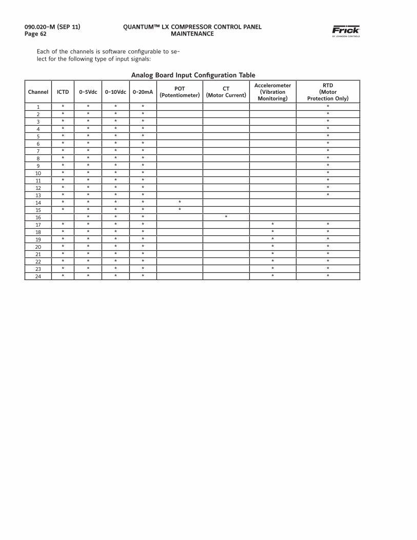
QUANTUM™ LX COMPRESSOR CONTROL PANELMAINTENANCE
090.020-M (SEP 11)Page 62
Each of the channels is software confi gurable to se-lect for the following type of input signals:
Analog Board Input Confi guration Table
Channel ICTD 0-5Vdc 0-10Vdc 0-20mAPOT
(Potentiometer)CT
(Motor Current)
Accelerometer(Vibration
Monitoring)
RTD(Motor
Protection Only)
1 * * * * *2 * * * * *3 * * * * *4 * * * * *5 * * * * *6 * * * * *7 * * * * *8 * * * * *9 * * * * *10 * * * * *11 * * * * *12 * * * * *13 * * * * *14 * * * * *15 * * * * *16 * * * *17 * * * * * *18 * * * * * *19 * * * * * *20 * * * * * *21 * * * * * *22 * * * * * *23 * * * * * *24 * * * * * *
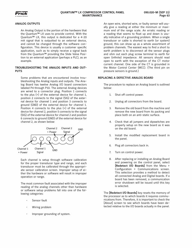
QUANTUM™ LX COMPRESSOR CONTROL PANELMAINTENANCE
090.020-M (SEP 11)Page 63
ANALOG OUTPUTS
An Analog Output is the portion of the hardware that the Quantum™ LX uses to provide control. With the Quantum™ LX, this output is dedicated for a 4-20 mA signal that is outputted to an external device, and cannot be changed through the software con-fi guration. This device is usually a customer specifi c application, such as to simply receive a signal back from the Quantum™ providing the Slide Valve Posi-tion to an external application (perhaps a PLC), as an example.
TROUBLESHOOTING THE ANALOG INPUTS AND OUT-PUTS
Some problems that are encountered involve trou-bleshooting the Analog inputs and outputs. The Ana-log Board has twelve Analog I/O board connectors labeled P4 through P10. The external Analog devices are wired to a connector plug. Position 1 connects to the plus (+) of the external device for channel 1, position 2 connects to the signal (SIG) of the exter-nal device for channel 1 and position 3 connects to ground (GND) of the external device for channel 1. Position 4 connects to the plus (+) of the external device for channel 2, position 5 connects to the signal (SIG) of the external device for channel 2 and position 6 connects to ground (GND) of the external device for channel 2, as shown below:
GND
Channel 2 + Power
Channel 1 + Power
Channel 1 Signal
Channel 2 Signal
GND
Each channel is setup through software calibration for the proper transducer type and range, and each transducer must be calibrated through the appropri-ate sensor calibration screen. Improper setup of ei-ther the hardware or software will result in improper operation or range.
The most common fault associated with the improper reading of the analog channels other than hardware or software setup problems fall into one of the fol-lowing categories:
• Sensor fault
• Wiring problem
• Improper grounding of system.
An open wire, shorted wire, or faulty sensor will usu-ally give a reading at either the minimum or maxi-mum end of the range scale. An erratic reading or a reading that seems to fl oat up and down is usu-ally indicative of a grounding problem. When a single transducer or cable is shorted to earth (or system) ground, this can show up as a whole assortment of problem channels. The easiest way to fi nd a short to earth problem is to disconnect all the sensor plugs and ohm out each plug screw terminal to earth for open (infi nite) impedance. All sensors should read open to earth with the exception of the CT motor current channel. One side of the CT is grounded in the Motor Control Center (MCC). (The third pin on pressure sensors is ground.)
REPLACING A DEFECTIVE ANALOG BOARD
The procedure to replace an Analog board is outlined below:
1. Shut off control power.
2. Unplug all connectors from the board.
3. Remove the old board from the machine and remove the new board from its packing and place both on an anti-static surface.
4. Check that all jumpers and dipswitches are properly setup on the new board as it was on the old board.
5. Install the modifi ed replacement board in the panel.
6. Plug all connectors back in.
7. Turn on control power.
8. After replacing or installing an Analog Board and powering on the control panel, select [Redetect I/O Boards] from the Menu > Confi guration > Communications screen. This selection provides a method to detect all connected Analog and Digital boards. If a board has been removed, a communication error shutdown will be issued until this key is selected.
The [Redetect I/O Boards] key resets the memory of the processor as to which boards it requires commu-nications from. Therefore, it is important to check the [About] screen to see which boards have been de-tected relative to the I/O boards actually in the panel.
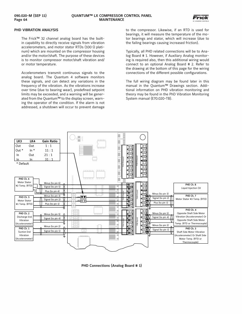
QUANTUM™ LX COMPRESSOR CONTROL PANELMAINTENANCE
090.020-M (SEP 11)Page 64
to the compressor. Likewise, if an RTD is used for bearings, it will measure the temperature of the mo-tor bearings and stator, which will increase (due to the failing bearings causing increased friction).
Typically, all PHD related connections will be to Ana-log Board # 1. However, if Auxiliary Analog monitor-ing is required also, then this additional wiring would connect to an optional Analog Board # 2. Refer to the drawing at the bottom of this page for the wiring connections of the different possible confi gurations.
The full wiring diagram may be found later in this manual in the Quantum™ Drawings section. Addi-tional information on PHD vibration monitoring and theory may be found in the PhD Vibration Monitoring System manual (E70.020-TB).
PHD Connections (Analog Board # 1)
PHD VIBRATION ANALYSIS
The Frick™ 32 channel analog board has the built-in capability to directly receive signals from vibration accelerometers, and motor stator RTDs (100 Ω plati-num) which are mounted on the compressor housing and/or the motor/shaft. The purpose of these devices is to monitor compressor motor/shaft vibration and/or motor temperature.
Accelerometers transmit continuous signals to the analog board. The Quantum 4 software monitors these signals, and can detect any variations in the frequency of the vibration. As the vibrations increase over time (due to bearing wear), predefi ned setpoint limits may be exceeded, and a warning will be gener-ated from the Quantum™ to the display screen, warn-ing the operator of the condition. If the alarm is not addressed, a shutdown will occur to prevent damage
Par
t #
: 64
0D
0168
H01
Rev
isio
n:
P9A
(In
puts
)
P9B
(In
puts
)
1 2
3 4
5 6
7 8
U4
SW
1
Ope
n D
5 24
VD
C
U9
PHHD ChD Ch.. 11 Suction End
Vibration (Accelerometer)
PHHD ChD Ch.. 22 Discharge End
Vibration (Accelerometer)
PHHD ChD Ch.. 55 Motor Stator
#1 Temp. (RTD)
PHHD ChD Ch.. 66 Motor Stator
#2 Temp. (RTD)
Signal (to pin 1)
Minus (to pin 2)
Signal (to pin 4) Minus (to pin 5)
Signal (to pin 5) Plus (to pin 4)
Minus (to pin 6)
Signal (to pin 2) Plus (to pin 1)
Minus (to pin 3)
P10
A (
Inpu
ts)
P10
B (
Inpu
ts)
P11B
(O
utpu
ts)
P11A
(O
utpu
ts)
P1
Signal (to pin 1)
Plus (to pin 1)
Signal (to pin 2)
Minus (to pin 5) Signal (to pin 4)
Minus (to pin 2)
Minus (to pin 3)
PHHD ChD Ch.. 44 Opposite Shaft Side Motor
Vibration (Accelerometer) Or Opposite Shaft Side Motor
Temp. (RTD or Thermocouple)
PHHD ChD Ch.. 88 Liquid Injection Oil
PHHD ChD Ch.. 33 Shaft Side Motor Vibration
(Accelerometer) Or Shaft Side Motor Temp. (RTD or
Thermocouple)
PHHD ChD Ch. . 7 Motor Stator #3 Temp. (RTD)
LK3 LK4 Gain Ratio Out Out 1 : 1 Out * In * 11 : 1 In Out 21 : 1 In In 31 : 1 * Default
LK3 LK4
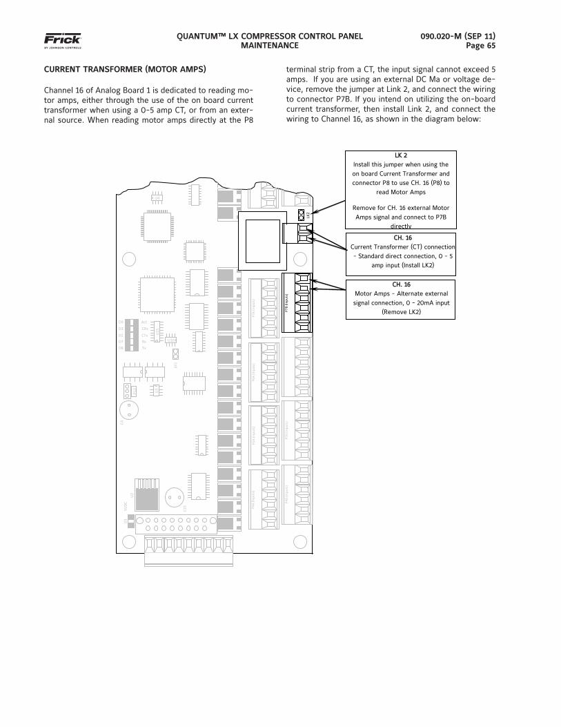
QUANTUM™ LX COMPRESSOR CONTROL PANELMAINTENANCE
090.020-M (SEP 11)Page 65
CURRENT TRANSFORMER (MOTOR AMPS)
Channel 16 of Analog Board 1 is dedicated to reading mo-tor amps, either through the use of the on board current transformer when using a 0-5 amp CT, or from an exter-nal source. When reading motor amps directly at the P8
terminal strip from a CT, the input signal cannot exceed 5 amps. If you are using an external DC Ma or voltage de-vice, remove the jumper at Link 2, and connect the wiring to connector P7B. If you intend on utilizing the on-board current transformer, then install Link 2, and connect the wiring to Channel 16, as shown in the diagram below:
P4A
(Inp
uts)
P4B
(Inp
uts)
CH. 16CH. 16 Current Transformer (CT) connection
- Standard direct connection, 0 - 5 amp input (Install LK2)
LK 2LK 2 Install this jumper when using the
on board Current Transformer and connector P8 to use CH. 16 (P8) to
read Motor Amps
Remove for CH. 16 external Motor
Amps signal and connect to P7B directly
CH. 16CH. 16 Motor Amps - Alternate external
signal connection, 0 - 20mA input (Remove LK2)
D1
C25
U2
5VD
C
P5A
(Inp
uts)
U4
P5B
(Inp
uts)
C4
LK1
U15
U3
U10
D9 Act D3 CRx D2 CTx D7 Rx D8 Tx
P12
P6A
(Inp
uts)
P7
A (I
nput
s)
LK2
P7B
(Inp
uts)
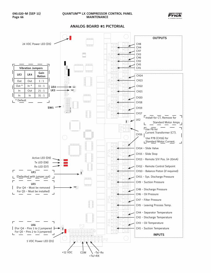
QUANTUM™ LX COMPRESSOR CONTROL PANELMAINTENANCE
090.020-M (SEP 11)Page 66
ANALOG BOARD #1 PICTORIAL
Install for CT, Remove for
Standard Motor Amps.
OUTPUTS
CH1 - Suction Temperature
CH2 - Discharge Temperature
CH3 - Oil Temperature
CH4 - Separator Temperature
CH5 - Leaving Process Temp.
CH6 - Oil Pressure
CH7 - Filter Pressure
CH8 - Discharge Pressure
CH9 - Suction Pressure
CH10 - Balance Piston (if required)
CH11 - Sys. Discharge Pressure
CH12 - Remote Control Setpoint
CH13 - Remote S/V Pos. (4-20mA)
CH14 - Slide Valve
CH15 - Slide Stop
Use P8 forCurrent Transformer (CT).
Use P7B (CH16) for Standard Motor Current.
CH16
LK2
CH1
CH2CH5
CH6
CH17
CH18
CH19
CH20
CH21
CH23
CH22
CH24
CH3
CH4CH7
CH8
INPUTS
Active LED (D9)
Tx LED (D8)
Rx LED (D7)
5 VDC Power LED (D1)
LK3LK4
24 VDC Power LED (D5)
SW1
+12 VDC COM+Tx/+RX
-Tx/-Rx
Vibration Jumpers
LK3 LK4Gain
Ration
Out Out 1 : 1
Out * In * 11 : 1
In Out 21 : 1
In In 31 : 1
* Default
LK5(For Q4 - Must be removedFor Q5 - Must be installed)
LK6(For Q4 - Pins 1 to 2 jumperedFor Q5 - Pins 2 to 3 jumpered)
LK1
(Defaulted with jumper out)
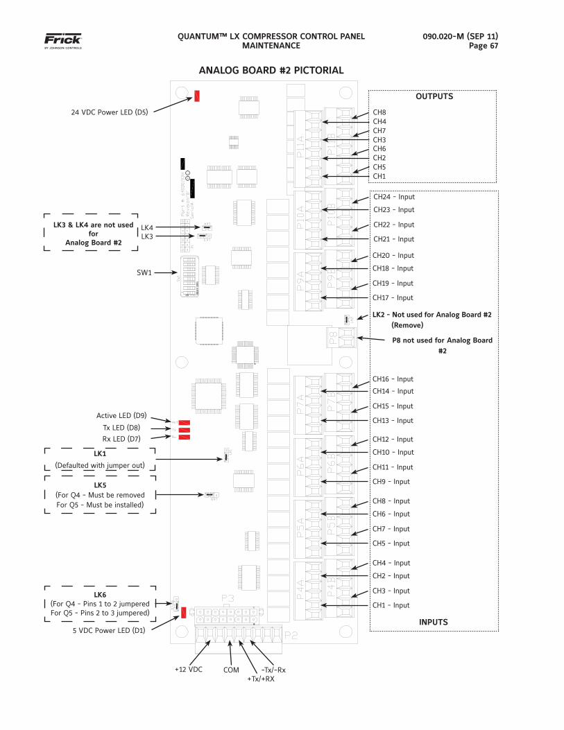
QUANTUM™ LX COMPRESSOR CONTROL PANELMAINTENANCE
090.020-M (SEP 11)Page 67
LK3LK4
SW1
LK3 & LK4 are not used for
Analog Board #2
ANALOG BOARD #2 PICTORIAL
CH1 - Input
CH2 - Input
CH3 - Input
CH4 - Input
CH5 - Input
CH6 - Input
CH7 - Input
CH8 - Input
CH9 - Input
CH10 - Input
CH11 - Input
CH12 - Input
CH13 - Input
CH14 - Input
CH15 - Input
P8 not used for Analog Board#2
CH16 - Input
LK2 - Not used for Analog Board #2 (Remove)
CH1
CH2CH5
CH6
CH17 - Input
CH18 - Input
CH19 - Input
CH20 - Input
CH21 - Input
CH23 - Input
CH22 - Input
CH24 - Input
CH3
CH4CH7
CH8
INPUTS5 VDC Power LED (D1)
24 VDC Power LED (D5)
+12 VDC COM+Tx/+RX
-Tx/-Rx
OUTPUTS
LK5(For Q4 - Must be removedFor Q5 - Must be installed)
LK6(For Q4 - Pins 1 to 2 jumperedFor Q5 - Pins 2 to 3 jumpered)
Active LED (D9)
Tx LED (D8)
Rx LED (D7)
LK1
(Defaulted with jumper out)
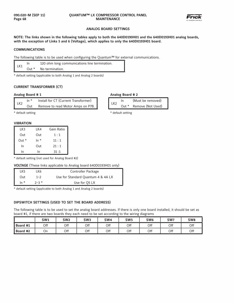
QUANTUM™ LX COMPRESSOR CONTROL PANELMAINTENANCE
090.020-M (SEP 11)Page 68
ANALOG BOARD SETTINGS
NOTE: The links shown in the following tables apply to both the 640D0190H01 and the 640D0193H01 analog boards, with the exception of Links 5 and 6 (Voltage), which applies to only the 640D0193H01 board.
COMMUNICATIONS
The following table is to be used when confi guring the Quantum™ for external communications.
LK1In 120 ohm long communications line termination.
Out * No termination.
* default setting (applicable to both Analog 1 and Analog 2 boards)
CURRENT TRANSFORMER (CT)
Analog Board # 1 Analog Board # 2
LK2In * Install for CT (Current Transformer)
LK2In (Must be removed)
Out Remove to read Motor Amps on P7B. Out * Remove (Not Used)
* default setting * default setting
VIBRATION
LK3 LK4 Gain Ratio
Out Out 1 : 1
Out * In * 11 : 1
In Out 21 : 1
In In 31 :1
* default setting (not used for Analog Board #2)
VOLTAGE (These links applicable to Analog board 640D0193H01 only)
LK5 LK6 Controller Package
Out 1-2 Use for Standard Quantum 4 & 4A LX
In * 2-3 * Use for Q5 LX
* default setting (applicable to both Analog 1 and Analog 2 boards)
DIPSWITCH SETTINGS (USED TO SET THE BOARD ADDRESS)
The following table is to be used to set the analog board addresses. If there is only one board installed, it should be set as board #1, if there are two boards they each need to be set according to the wiring diagrams
SW1 SW2 SW3 SW4 SW5 SW6 SW7 SW8
Board #1 Off Off Off Off Off Off Off Off
Board #2 On Off Off Off Off Off Off Off
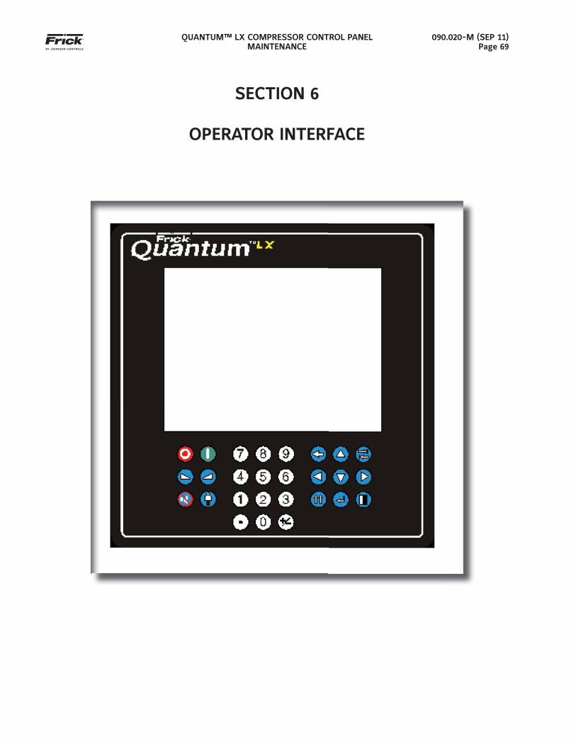
QUANTUM™ LX COMPRESSOR CONTROL PANELMAINTENANCE
090.020-M (SEP 11)Page 69
SECTION 6
OPERATOR INTERFACE
QUANTUM™ LX COMPRESSOR CONTROL PANELMAINTENANCE
090.020-M (SEP 11)Page 70
OPERATOR INTERFACE
DESCRIPTION
The Quantum™ LX Operator Interface actually con-sists of two components: A color 10-1/2” (diagonally measured) graphic display and a membrane touch keypad. The display is used to view information com-ing from the Quantum™ controller, while the keypad allows the user to enter information into the control-ler.
DISPLAY ASSEMBLY
The Display assembly consists of a 640 x 480 resolu-tion, LCD screen (which includes a fl uorescent back-light tube(s), a backlight inverter circuit board, and a wiring harness). Refer to the Parts List near the end of this manual for specifi c replacement part numbers.
NOTE: Before replacing a display unit, ensure that the symptom is not actually being caused by a bad fl uorescent tube, inverter or harness.
IDENTIFYING THE TYPE OF DISPLAY
Various display manufacturers have been utilized over the years, and although the variations between the displays of these manufacturers is subtle, it needs to be addressed here. If a display related problem is ever encountered and factory service is contacted, they may request the type of display that is being diagnosed. This information can be found on a sticker located on the back of the display mounting plate, and should resemble the following example:
This sticker will give the part number of the display that is currently installed. Refer to the Spare Parts list at the end of this manual for applicable part numbers.
DISPLAY REPLACEMENT
1. Shut off control power.
2. Carefully unplug all connectors that are attached to the display. Ensure that you are familiar with the relocation of each of these connectors.
3. Loosen the four hex nuts located on the display plate. The location of these nuts is shown on the Quantum 4 and Q5 Display Mounting Plate draw-ings that follow.
4. While supporting the display plate assembly with one hand, carefully remove the four hex nuts
that were loosened in the previous step.
5. Once the four nuts have been removed, care-fully remove the display plate. There is a section of plexiglas between the display and the clear viewing window of the keypad assembly. Ensure that this plexiglas does not come out. If it does come out, simply ensure that it is reinstalled be-fore placing the new display in place. Also be sure not to get fi ngerprints on the plexiglas.
6. Carefully lay the display plate down on a table or bench, with the display side up.
7. If you haven’t already done so, remove the con-nector from the back of the display. There are two variations on the way the display connector is attached depending on whether the unit is a Quantum 4 or Q5. Please refer to the notes pro-vided later in this section as to how to properly perform the cable removal.
8. Remove the four phillips head screws located near the corners of the display.
9. Remove the defective display.
10. Install the new display.
11. Reinstall the four phillips head screws near the four corners of the display. Do not overtighten.
12. Reconnect the display connector on the back of the display. Once again, refer to the two sections shown later as to the proper method to do this.
13. Reinstall the display plate back into position on the panel door, and loosely reinstall the four hex nuts, do not tighten yet.
14. Look at the front of the display from the front of the panel door. Ensure that the display looks centered in the display opening. Once centered, tighten the four hex nuts. Re-centering the dis-play may be necessary after these steps have been completed. If this is the case, simply loosen these four nuts, and re-center the display, then retighten.
15. Reattach all of the connectors that were re-moved during step 2.
16. Verify the Quantum™ jumper (link) settings per the table shown later in this section.
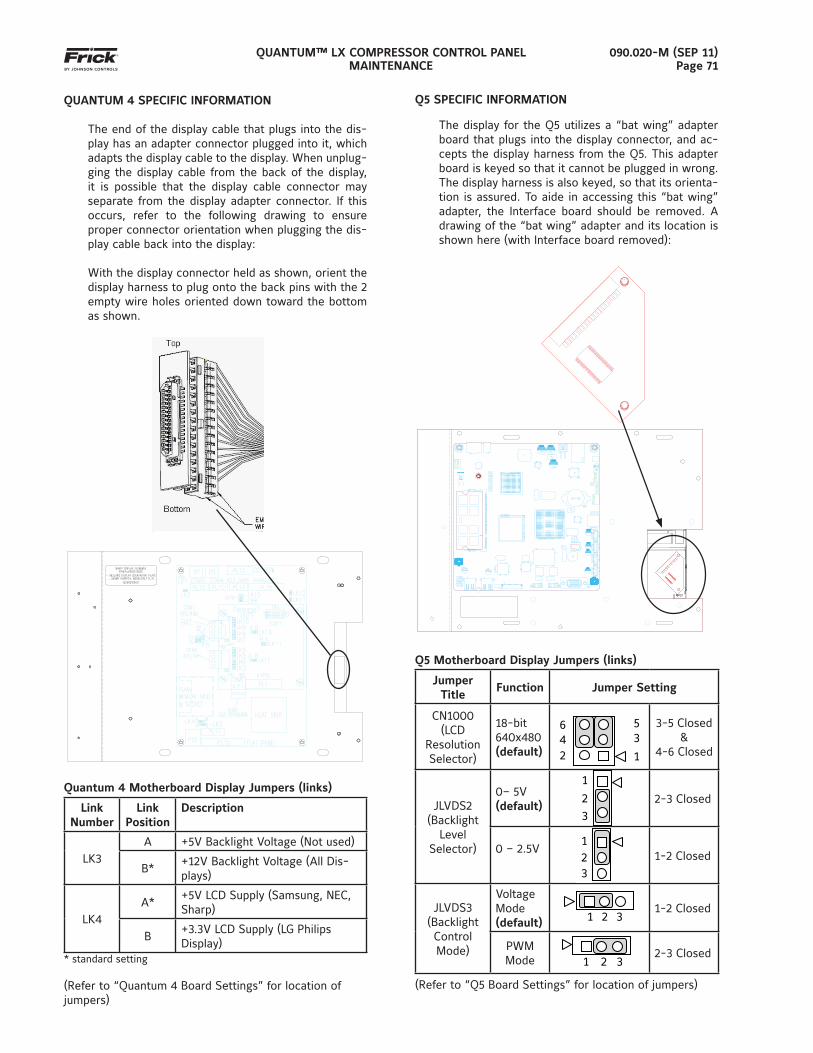
QUANTUM™ LX COMPRESSOR CONTROL PANELMAINTENANCE
090.020-M (SEP 11)Page 71
QUANTUM 4 SPECIFIC INFORMATION
The end of the display cable that plugs into the dis-play has an adapter connector plugged into it, which adapts the display cable to the display. When unplug-ging the display cable from the back of the display, it is possible that the display cable connector may separate from the display adapter connector. If this occurs, refer to the following drawing to ensure proper connector orientation when plugging the dis-play cable back into the display:
With the display connector held as shown, orient the display harness to plug onto the back pins with the 2 empty wire holes oriented down toward the bottom as shown.
Quantum 4 Motherboard Display Jumpers (links)
Link Number
Link Position
Description
LK3A +5V Backlight Voltage (Not used)
B*+12V Backlight Voltage (All Dis-plays)
LK4A*
+5V LCD Supply (Samsung, NEC, Sharp)
B+3.3V LCD Supply (LG Philips Display)
* standard setting
(Refer to “Quantum 4 Board Settings” for location of jumpers)
Q5 SPECIFIC INFORMATION
The display for the Q5 utilizes a “bat wing” adapter board that plugs into the display connector, and ac-cepts the display harness from the Q5. This adapter board is keyed so that it cannot be plugged in wrong. The display harness is also keyed, so that its orienta-tion is assured. To aide in accessing this “bat wing” adapter, the Interface board should be removed. A drawing of the “bat wing” adapter and its location is shown here (with Interface board removed):
Q5 Motherboard Display Jumpers (links)
Jumper Title
Function Jumper Setting
CN1000(LCD
Resolution Selector)
18-bit 640x480(default)
6
4
2
5 3
1
3-5 Closed&
4-6 Closed
JLVDS2(Backlight
LevelSelector)
0– 5V(default)
1
2
3 2-3 Closed
0 – 2.5V
1
2
3
1-2 Closed
JLVDS3(Backlight Control Mode)
Voltage Mode(default)
1 2 3 1-2 Closed
PWM Mode
1 2 3
2-3 Closed
(Refer to “Q5 Board Settings” for location of jumpers)
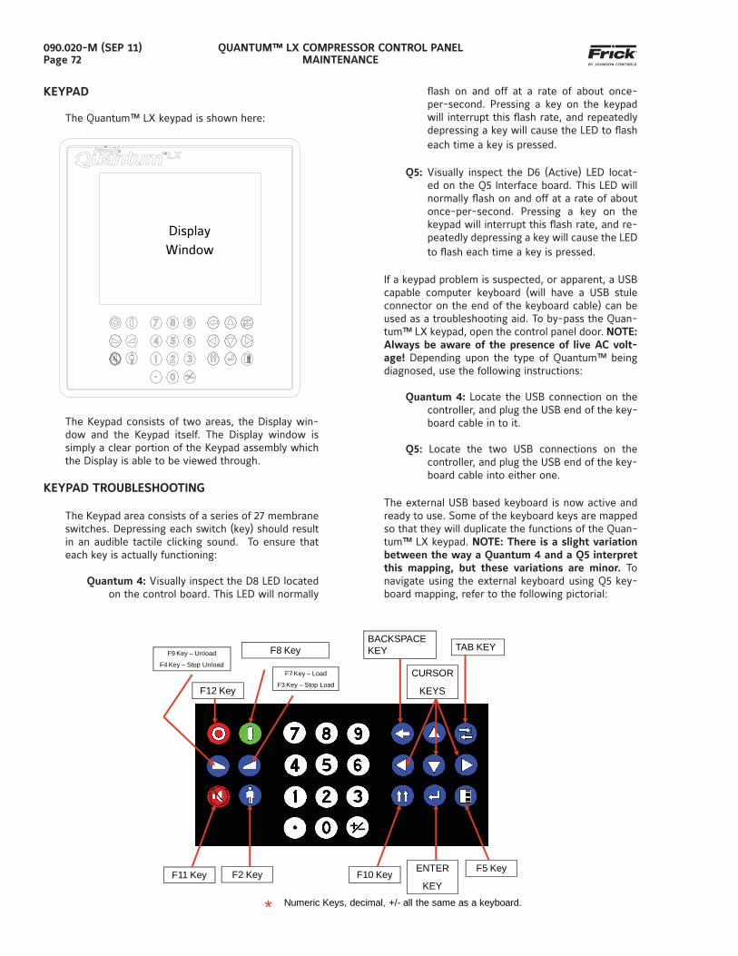
QUANTUM™ LX COMPRESSOR CONTROL PANELMAINTENANCE
090.020-M (SEP 11)Page 72
KEYPAD
The Quantum™ LX keypad is shown here:
Display Window
The Keypad consists of two areas, the Display win-dow and the Keypad itself. The Display window is simply a clear portion of the Keypad assembly which the Display is able to be viewed through.
KEYPAD TROUBLESHOOTING
The Keypad area consists of a series of 27 membrane switches. Depressing each switch (key) should result in an audible tactile clicking sound. To ensure that each key is actually functioning:
Quantum 4: Visually inspect the D8 LED located on the control board. This LED will normally
fl ash on and off at a rate of about once-per-second. Pressing a key on the keypad will interrupt this fl ash rate, and repeatedly depressing a key will cause the LED to fl ash each time a key is pressed.
Q5: Visually inspect the D6 (Active) LED locat-ed on the Q5 Interface board. This LED will normally fl ash on and off at a rate of about once-per-second. Pressing a key on the keypad will interrupt this fl ash rate, and re-peatedly depressing a key will cause the LED to fl ash each time a key is pressed.
If a keypad problem is suspected, or apparent, a USB capable computer keyboard (will have a USB stule connector on the end of the keyboard cable) can be used as a troubleshooting aid. To by-pass the Quan-tum™ LX keypad, open the control panel door. NOTE: Always be aware of the presence of live AC volt-age! Depending upon the type of Quantum™ being diagnosed, use the following instructions:
Quantum 4: Locate the USB connection on the controller, and plug the USB end of the key-board cable in to it.
Q5: Locate the two USB connections on the controller, and plug the USB end of the key-board cable into either one.
The external USB based keyboard is now active and ready to use. Some of the keyboard keys are mapped so that they will duplicate the functions of the Quan-tum™ LX keypad. NOTE: There is a slight variation between the way a Quantum 4 and a Q5 interpret this mapping, but these variations are minor. To navigate using the external keyboard using Q5 key-board mapping, refer to the following pictorial:
* Numeric Keys, decimal, +/- all the same as a keyboard.
TAB KEYBACKSPACE KEY
CURSOR
KEYS
ENTER
KEY
F5 KeyF10 KeyF11 Key F2 Key
F9 Key – Unload
F4 Key – Stop Unload
F12 Key
F7 Key – Load
F3 Key – Stop Load
F8 Key
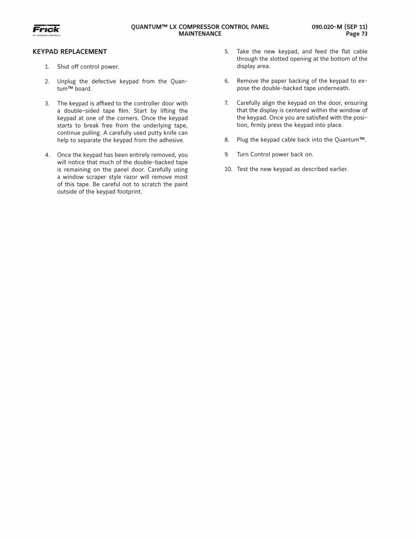
QUANTUM™ LX COMPRESSOR CONTROL PANELMAINTENANCE
090.020-M (SEP 11)Page 73
KEYPAD REPLACEMENT
1. Shut off control power.
2. Unplug the defective keypad from the Quan-tum™ board.
3. The keypad is affi xed to the controller door with a double-sided tape fi lm. Start by lifting the keypad at one of the corners. Once the keypad starts to break free from the underlying tape, continue pulling. A carefully used putty knife can help to separate the keypad from the adhesive.
4. Once the keypad has been entirely removed, you will notice that much of the double-backed tape is remaining on the panel door. Carefully using a window scraper style razor will remove most of this tape. Be careful not to scratch the paint outside of the keypad footprint.
5. Take the new keypad, and feed the fl at cable through the slotted opening at the bottom of the display area.
6. Remove the paper backing of the keypad to ex-pose the double-backed tape underneath.
7. Carefully align the keypad on the door, ensuring that the display is centered within the window of the keypad. Once you are satisfi ed with the posi-tion, fi rmly press the keypad into place.
8. Plug the keypad cable back into the Quantum™.
9. Turn Control power back on.
10. Test the new keypad as described earlier.

QUANTUM™ LX COMPRESSOR CONTROL PANELMAINTENANCE
090.020-M (SEP 11)Page 74
NOTES:
QUANTUM™ LX COMPRESSOR CONTROL PANELMAINTENANCE
090.020-M (SEP 11)Page 75
SECTION 7
SERVICE SCREENS
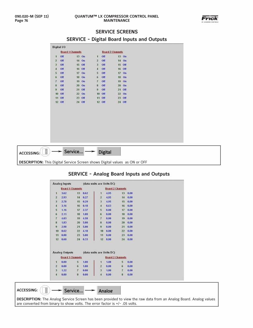
QUANTUM™ LX COMPRESSOR CONTROL PANELMAINTENANCE
090.020-M (SEP 11)Page 76
ACCESSING:
DESCRIPTION: The Analog Service Screen has been provided to view the raw data from an Analog Board. Analog values are converted from binary to show volts. The error factor is +/- .05 volts.
Service…Service… AnalogAnalog
SERVICE SCREENS
SERVICE - Digital Board Inputs and Outputs
Service…Service… DigitalDigital ACCESSING:
DESCRIPTION: This Digital Service Screen shows Digital values as ON or OFF
SERVICE - Analog Board Inputs and Outputs
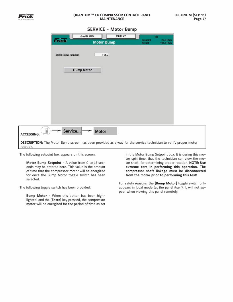
QUANTUM™ LX COMPRESSOR CONTROL PANELMAINTENANCE
090.020-M (SEP 11)Page 77
SERVICE - Motor Bump
ACCESSING:
Service…Service… Motor Motor Bump
DESCRIPTION: The Motor Bump screen has been provided as a way for the service technician to verify proper motor rotation.
The following setpoint box appears on this screen:
Motor Bump Setpoint - A value from 0 to 15 sec-onds may be entered here. This value is the amount of time that the compressor motor will be energized for once the Bump Motor toggle switch has been selected.
The following toggle switch has been provided:
Bump Motor - When this button has been high-lighted, and the [Enter] key pressed, the compressor motor will be energized for the period of time as set
in the Motor Bump Setpoint box. It is during this mo-tor spin time, that the technician can view the mo-tor shaft, for determining proper rotation. NOTE: Use extreme care in performing this operation. The compressor shaft linkage must be disconnected from the motor prior to performing this test!
For safety reasons, the [Bump Motor] toggle switch only appears in local mode (at the panel itself). It will not ap-pear when viewing this panel remotely.
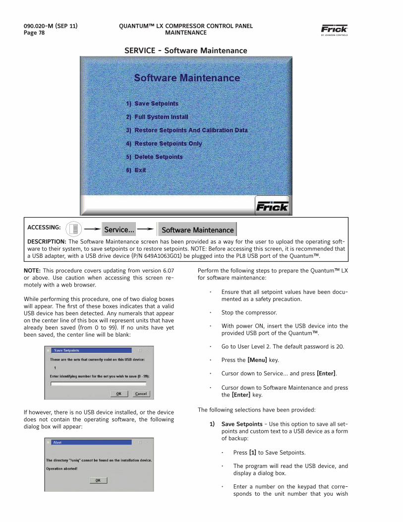
QUANTUM™ LX COMPRESSOR CONTROL PANELMAINTENANCE
090.020-M (SEP 11)Page 78
SERVICE - Software Maintenance
ACCESSING:
DESCRIPTION: The Software Maintenance screen has been provided as a way for the user to upload the operating soft-ware to their system, to save setpoints or to restore setpoints. NOTE: Before accessing this screen, it is recommended that a USB adapter, with a USB drive device (P/N 649A1063G01) be plugged into the PL8 USB port of the Quantum™.
NOTE: This procedure covers updating from version 6.07 or above. Use caution when accessing this screen re-motely with a web browser.
While performing this procedure, one of two dialog boxes will appear. The fi rst of these boxes indicates that a valid USB device has been detected. Any numerals that appear on the center line of this box will represent units that have already been saved (from 0 to 99). If no units have yet been saved, the center line will be blank:
If however, there is no USB device installed, or the device does not contain the operating software, the following dialog box will appear:
Perform the following steps to prepare the Quantum™ LX for software maintenance:
• Ensure that all setpoint values have been docu-mented as a safety precaution.
• Stop the compressor.
• With power ON, insert the USB device into the provided USB port of the Quantum™.
• Go to User Level 2. The default password is 20.
• Press the [Menu] key.
• Cursor down to Service… and press [Enter].
• Cursor down to Software Maintenance and press the [Enter] key.
The following selections have been provided:
1) Save Setpoints - Use this option to save all set-points and custom text to a USB device as a form of backup:
• Press [1] to Save Setpoints.
• The program will read the USB device, and display a dialog box.
• Enter a number on the keypad that corre-sponds to the unit number that you wish
Service…Service… Software MaintenanceSoftware Maintenance
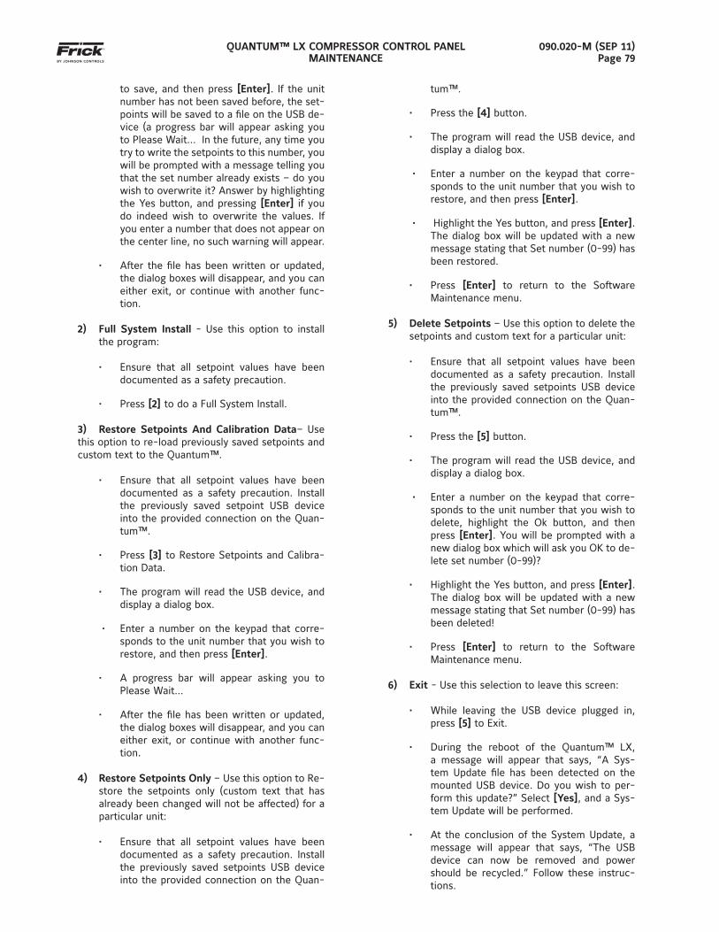
QUANTUM™ LX COMPRESSOR CONTROL PANELMAINTENANCE
090.020-M (SEP 11)Page 79
to save, and then press [Enter]. If the unit number has not been saved before, the set-points will be saved to a fi le on the USB de-vice (a progress bar will appear asking you to Please Wait… In the future, any time you try to write the setpoints to this number, you will be prompted with a message telling you that the set number already exists – do you wish to overwrite it? Answer by highlighting the Yes button, and pressing [Enter] if you do indeed wish to overwrite the values. If you enter a number that does not appear on the center line, no such warning will appear.
• After the fi le has been written or updated, the dialog boxes will disappear, and you can either exit, or continue with another func-tion.
2) Full System Install - Use this option to install the program:
• Ensure that all setpoint values have been documented as a safety precaution.
• Press [2] to do a Full System Install.
3) Restore Setpoints And Calibration Data– Use this option to re-load previously saved setpoints and custom text to the Quantum™.
• Ensure that all setpoint values have been documented as a safety precaution. Install the previously saved setpoint USB device into the provided connection on the Quan-tum™.
• Press [3] to Restore Setpoints and Calibra-tion Data.
• The program will read the USB device, and display a dialog box.
• Enter a number on the keypad that corre-sponds to the unit number that you wish to restore, and then press [Enter].
• A progress bar will appear asking you to Please Wait…
• After the fi le has been written or updated, the dialog boxes will disappear, and you can either exit, or continue with another func-tion.
4) Restore Setpoints Only – Use this option to Re-store the setpoints only (custom text that has already been changed will not be affected) for a particular unit:
• Ensure that all setpoint values have been documented as a safety precaution. Install the previously saved setpoints USB device into the provided connection on the Quan-
tum™.
• Press the [4] button.
• The program will read the USB device, and display a dialog box.
• Enter a number on the keypad that corre-sponds to the unit number that you wish to restore, and then press [Enter].
• Highlight the Yes button, and press [Enter]. The dialog box will be updated with a new message stating that Set number (0-99) has been restored.
• Press [Enter] to return to the Software Maintenance menu.
5) Delete Setpoints – Use this option to delete the setpoints and custom text for a particular unit:
• Ensure that all setpoint values have been documented as a safety precaution. Install the previously saved setpoints USB device into the provided connection on the Quan-tum™.
• Press the [5] button.
• The program will read the USB device, and display a dialog box.
• Enter a number on the keypad that corre-sponds to the unit number that you wish to delete, highlight the Ok button, and then press [Enter]. You will be prompted with a new dialog box which will ask you OK to de-lete set number (0-99)?
• Highlight the Yes button, and press [Enter]. The dialog box will be updated with a new message stating that Set number (0-99) has been deleted!
• Press [Enter] to return to the Software Maintenance menu.
6) Exit - Use this selection to leave this screen:
• While leaving the USB device plugged in, press [5] to Exit.
• During the reboot of the Quantum™ LX, a message will appear that says, “A Sys-tem Update fi le has been detected on the mounted USB device. Do you wish to per-form this update?” Select [Yes], and a Sys-tem Update will be performed.
• At the conclusion of the System Update, a message will appear that says, “The USB device can now be removed and power should be recycled.” Follow these instruc-tions.
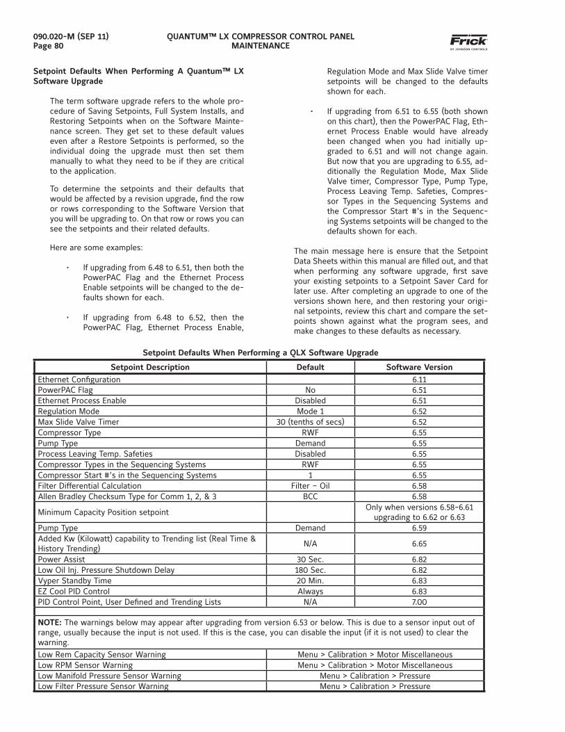
QUANTUM™ LX COMPRESSOR CONTROL PANELMAINTENANCE
090.020-M (SEP 11)Page 80
Regulation Mode and Max Slide Valve timer setpoints will be changed to the defaults shown for each.
• If upgrading from 6.51 to 6.55 (both shown on this chart), then the PowerPAC Flag, Eth-ernet Process Enable would have already been changed when you had initially up-graded to 6.51 and will not change again. But now that you are upgrading to 6.55, ad-ditionally the Regulation Mode, Max Slide Valve timer, Compressor Type, Pump Type, Process Leaving Temp. Safeties, Compres-sor Types in the Sequencing Systems and the Compressor Start #’s in the Sequenc-ing Systems setpoints will be changed to the defaults shown for each.
The main message here is ensure that the Setpoint Data Sheets within this manual are fi lled out, and that when performing any software upgrade, fi rst save your existing setpoints to a Setpoint Saver Card for later use. After completing an upgrade to one of the versions shown here, and then restoring your origi-nal setpoints, review this chart and compare the set-points shown against what the program sees, and make changes to these defaults as necessary.
Setpoint Defaults When Performing a QLX Software Upgrade
Setpoint Description Default Software Version
Ethernet Confi guration 6.11PowerPAC Flag No 6.51Ethernet Process Enable Disabled 6.51Regulation Mode Mode 1 6.52Max Slide Valve Timer 30 (tenths of secs) 6.52Compressor Type RWF 6.55Pump Type Demand 6.55Process Leaving Temp. Safeties Disabled 6.55Compressor Types in the Sequencing Systems RWF 6.55Compressor Start #’s in the Sequencing Systems 1 6.55Filter Differential Calculation Filter – Oil 6.58Allen Bradley Checksum Type for Comm 1, 2, & 3 BCC 6.58
Minimum Capacity Position setpointOnly when versions 6.58-6.61
upgrading to 6.62 or 6.63Pump Type Demand 6.59Added Kw (Kilowatt) capability to Trending list (Real Time & History Trending)
N/A 6.65
Power Assist 30 Sec. 6.82Low Oil Inj. Pressure Shutdown Delay 180 Sec. 6.82Vyper Standby Time 20 Min. 6.83EZ Cool PID Control Always 6.83PID Control Point, User Defi ned and Trending Lists N/A 7.00
NOTE: The warnings below may appear after upgrading from version 6.53 or below. This is due to a sensor input out of range, usually because the input is not used. If this is the case, you can disable the input (if it is not used) to clear the warning.
Low Rem Capacity Sensor Warning Menu > Calibration > Motor MiscellaneousLow RPM Sensor Warning Menu > Calibration > Motor MiscellaneousLow Manifold Pressure Sensor Warning Menu > Calibration > PressureLow Filter Pressure Sensor Warning Menu > Calibration > Pressure
Setpoint Defaults When Performing A Quantum™ LX Software Upgrade
The term software upgrade refers to the whole pro-cedure of Saving Setpoints, Full System Installs, and Restoring Setpoints when on the Software Mainte-nance screen. They get set to these default values even after a Restore Setpoints is performed, so the individual doing the upgrade must then set them manually to what they need to be if they are critical to the application.
To determine the setpoints and their defaults that would be affected by a revision upgrade, fi nd the row or rows corresponding to the Software Version that you will be upgrading to. On that row or rows you can see the setpoints and their related defaults.
Here are some examples:
• If upgrading from 6.48 to 6.51, then both the PowerPAC Flag and the Ethernet Process Enable setpoints will be changed to the de-faults shown for each.
• If upgrading from 6.48 to 6.52, then the PowerPAC Flag, Ethernet Process Enable,
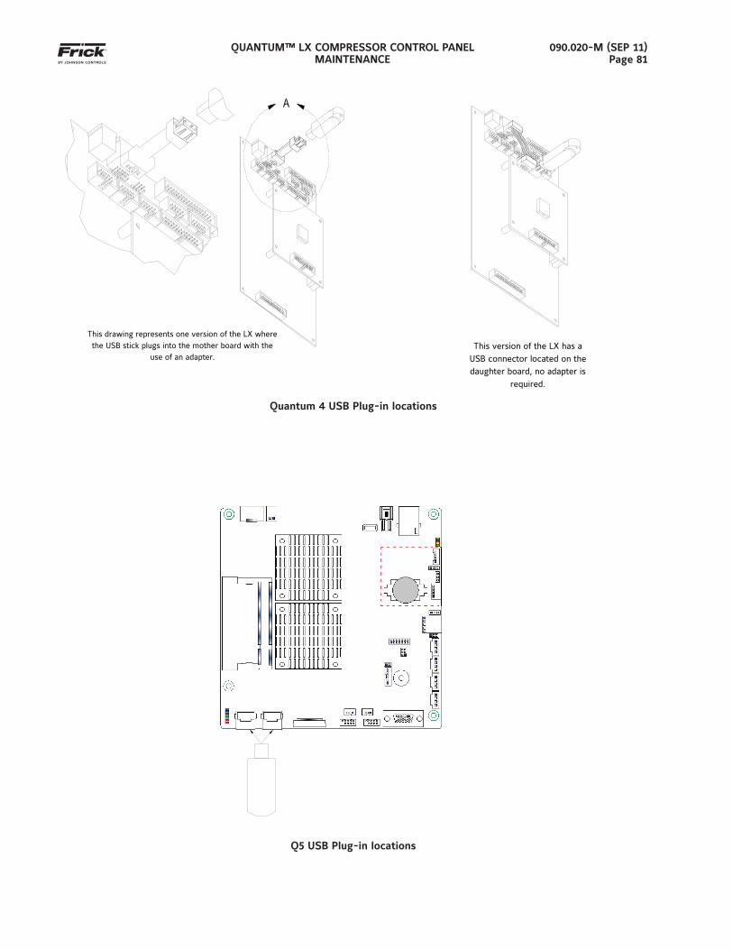
QUANTUM™ LX COMPRESSOR CONTROL PANELMAINTENANCE
090.020-M (SEP 11)Page 81
This drawing represents one version of the LX where the USB stick plugs into the mother board with the
use of an adapter.
Quantum 4 USB Plug-in locations
Q5 USB Plug-in locations
This version of the LX has a USB connector located on the daughter board, no adapter is
required.
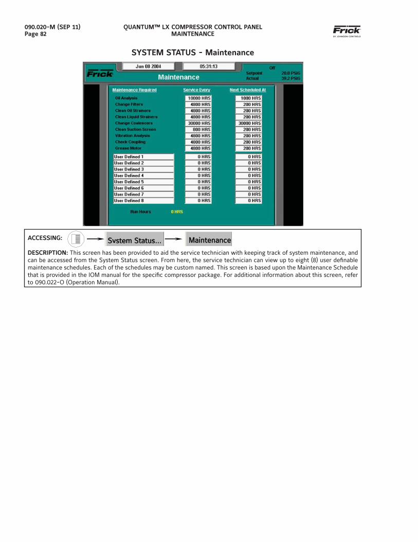
QUANTUM™ LX COMPRESSOR CONTROL PANELMAINTENANCE
090.020-M (SEP 11)Page 82
SYSTEM STATUS - Maintenance
ACCESSING:
DESCRIPTION: This screen has been provided to aid the service technician with keeping track of system maintenance, and can be accessed from the System Status screen. From here, the service technician can view up to eight (8) user defi nable maintenance schedules. Each of the schedules may be custom named. This screen is based upon the Maintenance Schedule that is provided in the IOM manual for the specifi c compressor package. For additional information about this screen, refer to 090.022-O (Operation Manual).
MaintenanceMaintenance System Status…System Status…
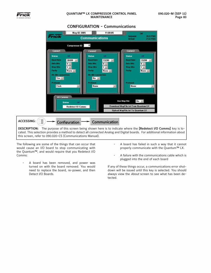
QUANTUM™ LX COMPRESSOR CONTROL PANELMAINTENANCE
090.020-M (SEP 11)Page 83
CONFIGURATION - Communications
ACCESSING:
DESCRIPTION: The purpose of this screen being shown here is to indicate where the [Redetect I/O Comms] key is lo-cated. This selection provides a method to detect all connected Analog and Digital boards. For additional information about this screen, refer to 090.020-CS (Communications Manual).
ConfigurationConfiguration…
CommunicationCommunications
The following are some of the things that can occur that would cause an I/O board to stop communicating with the Quantum™, and would require that you Redetect I/O Comms:
• A board has been removed, and power was turned on with the board removed. You would need to replace the board, re-power, and then Detect I/O Boards.
• A board has failed in such a way that it cannot properly communicate with the Quantum™ LX.
• A failure with the communications cable which is plugged into the end of each board
If any of these things occur, a communications error shut-down will be issued until this key is selected. You should always view the About screen to see what has been de-tected.
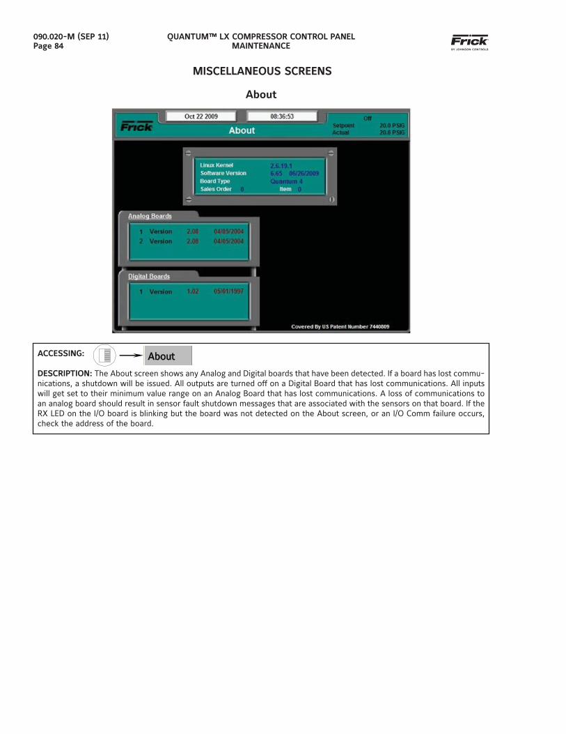
QUANTUM™ LX COMPRESSOR CONTROL PANELMAINTENANCE
090.020-M (SEP 11)Page 84
MISCELLANEOUS SCREENS
About
ACCESSING:
DESCRIPTION: The About screen shows any Analog and Digital boards that have been detected. If a board has lost commu-nications, a shutdown will be issued. All outputs are turned off on a Digital Board that has lost communications. All inputs will get set to their minimum value range on an Analog Board that has lost communications. A loss of communications to an analog board should result in sensor fault shutdown messages that are associated with the sensors on that board. If the RX LED on the I/O board is blinking but the board was not detected on the About screen, or an I/O Comm failure occurs, check the address of the board.
AboutAbout
QUANTUM™ LX COMPRESSOR CONTROL PANELMAINTENANCE
090.020-M (SEP 11)Page 85
SECTION 8
TROUBLESHOOTING
TROUBLESHOOTING A PROBLEM THAT APPEARS UNEXPLAINABLE
When there is a problem that makes no sense due to unexplainable things happening, check the following:
1. Is the panel powered by an isolating power source such as a control transformer in the start-er panel?
2. Verify that the panel is not powered from a light-ing or utility panel.
3. It is important to know if the unit ever worked properly.
4. If the unit used to work properly, try to deter-mine when the problem fi rst showed up.
3. It is important to know if the problem occurs randomly, frequently, or all the time.
4. Check what the temperature is in the engine room and at the panel. Is it very hot or very cold?
• Make sure that the motor is not blowing ex-haust air on the control panel.
5. If it just started to act up, then check if there was recently a severe lightning storm, fi re, fl ood, or a plant accident. If any of the following conditions are possible, then check for it:
• Has any water, refrigerant, or oil leaked into the panel or conduit?
• Does the conduit with the Slide Valve or Slide Stop contain liquid?
• Does the Slide Stop potentiometer cover contain any liquid?
6. If it just started to act up, then check if anything was recently changed in the system (i.e. soft-ware or hardware.)
7. If it just started to act up, then check if any ser-vice was recently done to the compressor or its electrical system?
8. If there is communication wiring connecting the panel to another panel or device, then check the
following:
• If the Quantum™ is unexplainably shutting down, try disconnecting the communica-tions cable to see if the problem goes away.
• Check if the communications cable shields are tied to machine ground at only one loca-tion. For a PLC or Opto22 based system, the shield should normally be tied only at the PLC or Opto22 panel.
• Check that you are using the Frickrecom-mended communications cable.
9. If this is an older plant, has the plant wiring been brought up to code?
10. Do you have power wiring mixed with control, sensor or communications wiring?
11. Check that the starter panel is grounded to the plant transformer. There are usually four wires: 3 for the 3 phases and 1 for plant ground.
12. Check that the motor is grounded to the start-er panel. There are usually four wires: 3 for the phases and 1 for ground.
13. Ensure that one side of the motor current trans-former is grounded in the motor starter panel. The wire to the control panel terminal #2 is usu-ally the only one grounded.
14. Check that the pressure transducers are properly grounded. The two types of transducers you may have are as follows: an older type has an 8 to 10 inch 3-conductor pigtail coming out of the trans-ducer. This type will have the attaching cable’s shield cut off and insulated at the transducer end. The shield is then tied to a panel ground terminal in the panel. The newer type has the cable as an integral part of the housing and has the shield crimped to the case at the transduc-er end. This type of transducer has the cable’s shield cut off and insulated in the control panel.
15. Check that the temperature transducers are properly grounded. The temperature probes
QUANTUM™ LX COMPRESSOR CONTROL PANELMAINTENANCE
090.020-M (SEP 11)Page 86
usually have two short wires coming out of the sensor, and are tied to a shielded cable at the thermal well head. The shield is insulated at the temperature probe and grounded at the panel end.
16. Check if one of the temperature probes has a signal wire shorted to machine ground. To do this, fi rst pull the orange plug from the micro board and then use a DVM and check each white wire to machine ground and each black wire to machine ground.
17. Check that all inductive loads (i.e. coils, sole-noids, or relays, etc.) connected to the I/O output modules have surge suppressers across them, preferably at the devices. Most of the larger fac-tory installed inductive loads should have surge suppressors as well.
18. If the compressor control settings unexplain-ably change modes, it may be a noise problem affecting the keypad’s input circuit. Check if it works OK with the keypad cable disconnected. If it works OK, then check the grounding as de-
scribed above. If the grounding is OK then re-place the keypad.
19. Make sure that you have a continuous ground back to the power source. The ground connec-tion must be aluminum or copper. A conduit ground will not work. Do not drive a ground stake at the compressor since extraneous cur-rents will be attracted to the compressor.
22. Make sure that there is no AC wiring lying next to the printed circuit board.
23. Unexplainable compressor auxiliary failures are usually indicative of noise due to wiring prob-lems (i.e. incorrect earth grounds, mixed power and control wiring, unsuppressed coils, etc)
24. If the compressor is unexplainably shutting down, check if the machine shares control transformer power with something else. Make sure each compressor has its own isolation transformer in the motor control center off the three-phase bus with the secondary properly grounded.
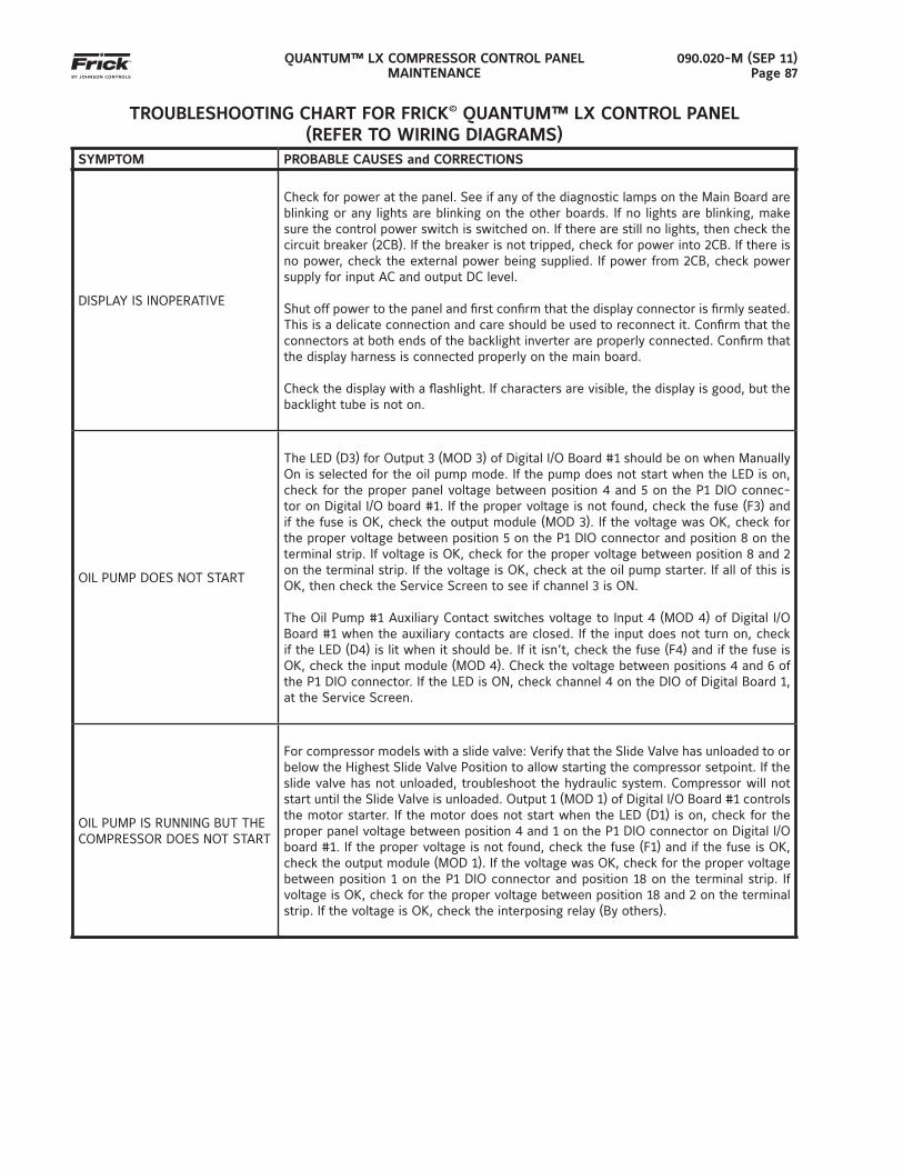
QUANTUM™ LX COMPRESSOR CONTROL PANELMAINTENANCE
090.020-M (SEP 11)Page 87
TROUBLESHOOTING CHART FOR FRICK© QUANTUM™ LX CONTROL PANEL(REFER TO WIRING DIAGRAMS)
SYMPTOM PROBABLE CAUSES and CORRECTIONS
DISPLAY IS INOPERATIVE
Check for power at the panel. See if any of the diagnostic lamps on the Main Board are blinking or any lights are blinking on the other boards. If no lights are blinking, make sure the control power switch is switched on. If there are still no lights, then check the circuit breaker (2CB). If the breaker is not tripped, check for power into 2CB. If there is no power, check the external power being supplied. If power from 2CB, check power supply for input AC and output DC level.
Shut off power to the panel and fi rst confi rm that the display connector is fi rmly seated. This is a delicate connection and care should be used to reconnect it. Confi rm that the connectors at both ends of the backlight inverter are properly connected. Confi rm that the display harness is connected properly on the main board.
Check the display with a fl ashlight. If characters are visible, the display is good, but the backlight tube is not on.
OIL PUMP DOES NOT START
The LED (D3) for Output 3 (MOD 3) of Digital I/O Board #1 should be on when Manually On is selected for the oil pump mode. If the pump does not start when the LED is on, check for the proper panel voltage between position 4 and 5 on the P1 DIO connec-tor on Digital I/O board #1. If the proper voltage is not found, check the fuse (F3) and if the fuse is OK, check the output module (MOD 3). If the voltage was OK, check for the proper voltage between position 5 on the P1 DIO connector and position 8 on the terminal strip. If voltage is OK, check for the proper voltage between position 8 and 2 on the terminal strip. If the voltage is OK, check at the oil pump starter. If all of this is OK, then check the Service Screen to see if channel 3 is ON.
The Oil Pump #1 Auxiliary Contact switches voltage to Input 4 (MOD 4) of Digital I/O Board #1 when the auxiliary contacts are closed. If the input does not turn on, check if the LED (D4) is lit when it should be. If it isn’t, check the fuse (F4) and if the fuse is OK, check the input module (MOD 4). Check the voltage between positions 4 and 6 of the P1 DIO connector. If the LED is ON, check channel 4 on the DIO of Digital Board 1, at the Service Screen.
OIL PUMP IS RUNNING BUT THE COMPRESSOR DOES NOT START
For compressor models with a slide valve: Verify that the Slide Valve has unloaded to or below the Highest Slide Valve Position to allow starting the compressor setpoint. If the slide valve has not unloaded, troubleshoot the hydraulic system. Compressor will not start until the Slide Valve is unloaded. Output 1 (MOD 1) of Digital I/O Board #1 controls the motor starter. If the motor does not start when the LED (D1) is on, check for the proper panel voltage between position 4 and 1 on the P1 DIO connector on Digital I/O board #1. If the proper voltage is not found, check the fuse (F1) and if the fuse is OK, check the output module (MOD 1). If the voltage was OK, check for the proper voltage between position 1 on the P1 DIO connector and position 18 on the terminal strip. If voltage is OK, check for the proper voltage between position 18 and 2 on the terminal strip. If the voltage is OK, check the interposing relay (By others).
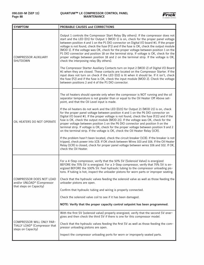
QUANTUM™ LX COMPRESSOR CONTROL PANELMAINTENANCE
090.020-M (SEP 11)Page 88
SYMPTOM PROBABLE CAUSES and CORRECTIONS
COMPRESSOR AUXILIARY SHUTDOWN
Output 1 controls the Compressor Start Relay (By others). If the compressor does not start and the LED (D1) for Output 1 (MOD 1) is on, check for the proper panel voltage between position 4 and 1 on the P1 DIO connector on Digital I/O board #1. If the proper voltage is not found, check the fuse (F1) and if the fuse is OK, check the output module (MOD 1). If the voltage was OK, check for the proper voltage between position 1 on the P1 DIO connector and position 18 on the terminal strip. If voltage is OK, check for the proper voltage between position 18 and 2 on the terminal strip. If the voltage is OK, check the interposing relay (By others).
The Compressor Starter Auxiliary Contacts turn on Input 2 (MOD 2) of Digital I/O Board #1 when they are closed. These contacts are located on the Compressor Starter. If the input does not turn on check if the LED (D2) is lit when it should be. If it isn’t, check the fuse (F2) and if the fuse is OK, check the input module (MOD 2). Check the voltage between positions 2 and 4 of the P1 DIO connector.
OIL HEATERS DO NOT OPERATE
The oil heaters should operate only when the compressor is NOT running and the oil separator temperature is not greater than or equal to the Oil Heater Off Above set-point, and that the Oil Level input is made.
If the oil heaters do not work and the LED (D21) for Output 21 (MOD 21) is on, check for the proper panel voltage between position 4 and 1 on the P6 DIO connector on Digital I/O board #1. If the proper voltage is not found, check the fuse (F21) and if the fuse is OK, check the output module (MOD 21). If the voltage was OK, check for the proper voltage between position 1 on the P6 DIO connector and position 9 on the terminal strip. If voltage is OK, check for the proper voltage between position 9 and 2 on the terminal strip. If the voltage is OK, check the Oil Heater Relay (1CR).
If the problem hasn’t been located, check the circuit breaker (1CB). If the breaker is not tripped, check power into 1CB. If OK check between Wires 103 and 106. If the Oil Heater Relay (1CR) is closed, check for proper panel voltage between wires 106 and 102. If OK, check the Oil Heater.
COMPRESSOR DOES NOT LOAD and/or UNLOAD* (Compressor that steps on Capacity)
For a 4-Step compressor, verify that the 50% SV (Solenoid Valve) is energized BEFORE the 75% SV is energized. For a 3-Step compressor, verify that 75% SV is en-ergized BEFORE the 100% SV. Feel hydraulic tubing to the compressor unloading pis-tons. If tubing is hot, inspect the unloader pistons for worn parts or improper seating.
Check that the hydraulic valves feeding the solenoid valve as well as those feeding the unloader pistons are open.
Confi rm that hydraulic tubing and wiring is properly connected.
Check the solenoid valve coil to see if it has been damaged.
NOTE: Verify that the proper capacity control setpoint has been programmed.
COMPRESSOR WILL ONLY PAR-TIALLY LOAD* (Compressor that steps on Capacity)
With the fi rst SV (solenoid valve) properly energized, verify that the second SV ener-gizes and then check the third SV if there is one for this compressor model.
Check that the hydraulic valves feeding the fi rst SV as well as those feeding the com-pressor unloading pistons are open.
Inspect the compressor unloading ports for worn or improperly seated parts.
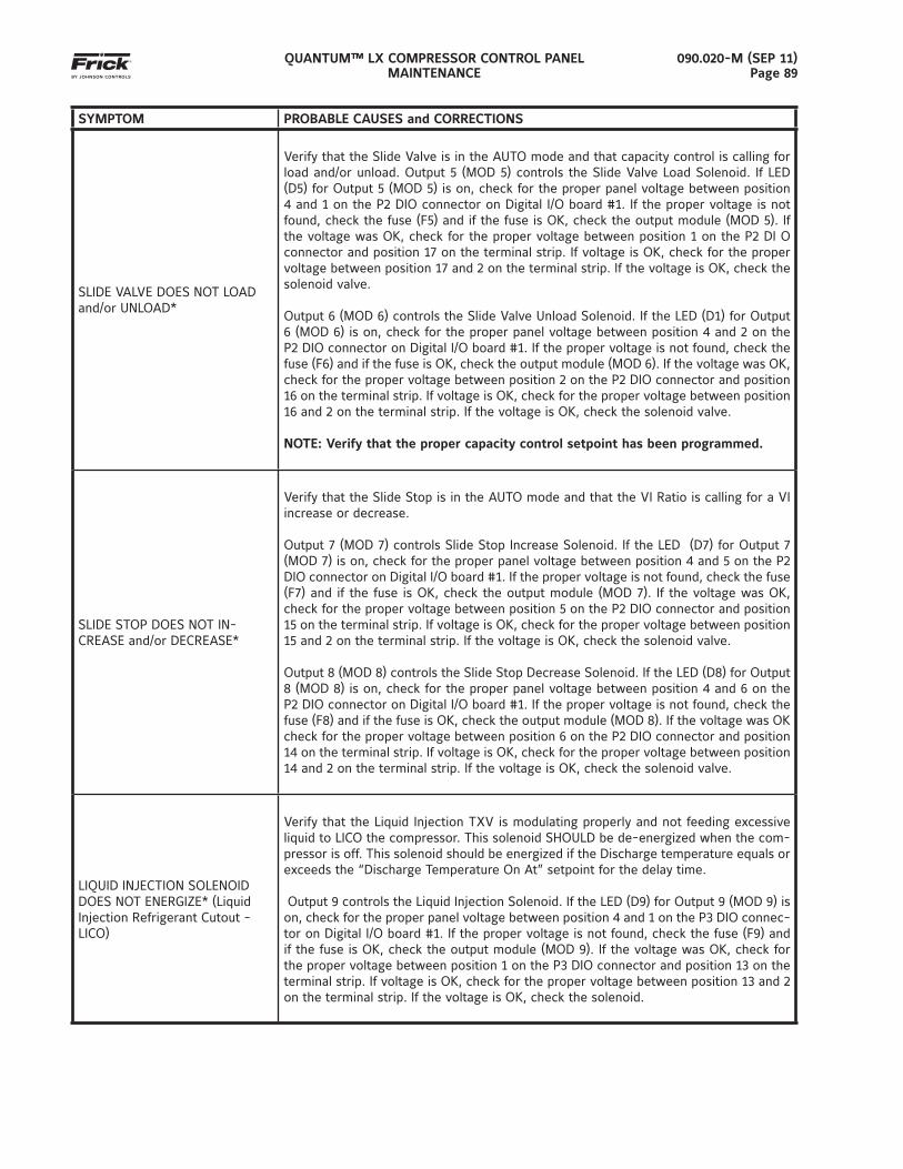
QUANTUM™ LX COMPRESSOR CONTROL PANELMAINTENANCE
090.020-M (SEP 11)Page 89
SYMPTOM PROBABLE CAUSES and CORRECTIONS
SLIDE VALVE DOES NOT LOAD and/or UNLOAD*
Verify that the Slide Valve is in the AUTO mode and that capacity control is calling for load and/or unload. Output 5 (MOD 5) controls the Slide Valve Load Solenoid. If LED (D5) for Output 5 (MOD 5) is on, check for the proper panel voltage between position 4 and 1 on the P2 DIO connector on Digital I/O board #1. If the proper voltage is not found, check the fuse (F5) and if the fuse is OK, check the output module (MOD 5). If the voltage was OK, check for the proper voltage between position 1 on the P2 DI O connector and position 17 on the terminal strip. If voltage is OK, check for the proper voltage between position 17 and 2 on the terminal strip. If the voltage is OK, check the solenoid valve.
Output 6 (MOD 6) controls the Slide Valve Unload Solenoid. If the LED (D1) for Output 6 (MOD 6) is on, check for the proper panel voltage between position 4 and 2 on the P2 DIO connector on Digital I/O board #1. If the proper voltage is not found, check the fuse (F6) and if the fuse is OK, check the output module (MOD 6). If the voltage was OK, check for the proper voltage between position 2 on the P2 DIO connector and position 16 on the terminal strip. If voltage is OK, check for the proper voltage between position 16 and 2 on the terminal strip. If the voltage is OK, check the solenoid valve.
NOTE: Verify that the proper capacity control setpoint has been programmed.
SLIDE STOP DOES NOT IN-CREASE and/or DECREASE*
Verify that the Slide Stop is in the AUTO mode and that the VI Ratio is calling for a VI increase or decrease.
Output 7 (MOD 7) controls Slide Stop Increase Solenoid. If the LED (D7) for Output 7 (MOD 7) is on, check for the proper panel voltage between position 4 and 5 on the P2 DIO connector on Digital I/O board #1. If the proper voltage is not found, check the fuse (F7) and if the fuse is OK, check the output module (MOD 7). If the voltage was OK, check for the proper voltage between position 5 on the P2 DIO connector and position 15 on the terminal strip. If voltage is OK, check for the proper voltage between position 15 and 2 on the terminal strip. If the voltage is OK, check the solenoid valve.
Output 8 (MOD 8) controls the Slide Stop Decrease Solenoid. If the LED (D8) for Output 8 (MOD 8) is on, check for the proper panel voltage between position 4 and 6 on the P2 DIO connector on Digital I/O board #1. If the proper voltage is not found, check the fuse (F8) and if the fuse is OK, check the output module (MOD 8). If the voltage was OK check for the proper voltage between position 6 on the P2 DIO connector and position 14 on the terminal strip. If voltage is OK, check for the proper voltage between position 14 and 2 on the terminal strip. If the voltage is OK, check the solenoid valve.
LIQUID INJECTION SOLENOID DOES NOT ENERGIZE* (Liquid Injection Refrigerant Cutout - LICO)
Verify that the Liquid Injection TXV is modulating properly and not feeding excessive liquid to LICO the compressor. This solenoid SHOULD be de-energized when the com-pressor is off. This solenoid should be energized if the Discharge temperature equals or exceeds the “Discharge Temperature On At” setpoint for the delay time.
Output 9 controls the Liquid Injection Solenoid. If the LED (D9) for Output 9 (MOD 9) is on, check for the proper panel voltage between position 4 and 1 on the P3 DIO connec-tor on Digital I/O board #1. If the proper voltage is not found, check the fuse (F9) and if the fuse is OK, check the output module (MOD 9). If the voltage was OK, check for the proper voltage between position 1 on the P3 DIO connector and position 13 on the terminal strip. If voltage is OK, check for the proper voltage between position 13 and 2 on the terminal strip. If the voltage is OK, check the solenoid.
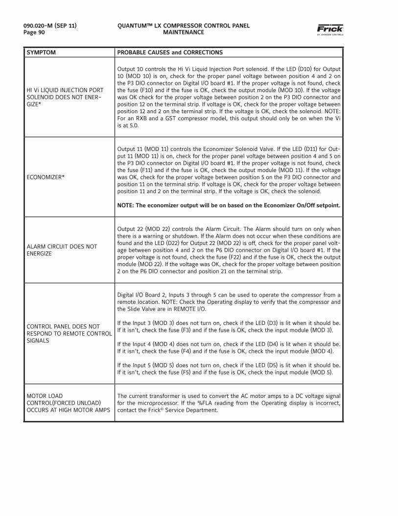
QUANTUM™ LX COMPRESSOR CONTROL PANELMAINTENANCE
090.020-M (SEP 11)Page 90
SYMPTOM PROBABLE CAUSES and CORRECTIONS
HI Vi LIQUID INJECTION PORT SOLENOID DOES NOT ENER-GIZE*
Output 10 controls the Hi Vi Liquid Injection Port solenoid. If the LED (D10) for Output 10 (MOD 10) is on, check for the proper panel voltage between position 4 and 2 on the P3 DIO connector on Digital I/O board #1. If the proper voltage is not found, check the fuse (F10) and if the fuse is OK, check the output module (MOD 10). If the voltage was OK check for the proper voltage between position 2 on the P3 DIO connector and position 12 on the terminal strip. If voltage is OK, check for the proper voltage between position 12 and 2 on the terminal strip. If the voltage is OK, check the solenoid. NOTE: For an RXB and a GST compressor model, this output should only be on when the Vi is at 5.0.
ECONOMIZER*
Output 11 (MOD 11) controls the Economizer Solenoid Valve. If the LED (D11) for Out-put 11 (MOD 11) is on, check for the proper panel voltage between position 4 and 5 on the P3 DIO connector on Digital I/O board #1. If the proper voltage is not found, check the fuse (F11) and if the fuse is OK, check the output module (MOD 11). If the voltage was OK, check for the proper voltage between position 5 on the P3 DIO connector and position 11 on the terminal strip. If voltage is OK, check for the proper voltage between position 11 and 2 on the terminal strip. If the voltage is OK, check the solenoid.
NOTE: The economizer output will be on based on the Economizer On/Off setpoint.
ALARM CIRCUIT DOES NOT ENERGIZE
Output 22 (MOD 22) controls the Alarm Circuit. The Alarm should turn on only when there is a warning or shutdown. If the Alarm does not occur when these conditions are found and the LED (D22) for Output 22 (MOD 22) is off, check for the proper panel volt-age between position 4 and 2 on the P6 DIO connector on Digital I/O board #1. If the proper voltage is not found, check the fuse (F22) and if the fuse is OK, check the output module (MOD 22). If the voltage was OK, check for the proper voltage between position 2 on the P6 DIO connector and position 21 on the terminal strip.
CONTROL PANEL DOES NOT RESPOND TO REMOTE CONTROL SIGNALS
Digital I/O Board 2, Inputs 3 through 5 can be used to operate the compressor from a remote location. NOTE: Check the Operating display to verify that the compressor and the Slide Valve are in REMOTE I/O.
If the Input 3 (MOD 3) does not turn on, check if the LED (D3) is lit when it should be. If it isn’t, check the fuse (F3) and if the fuse is OK, check the input module (MOD 3).
If the Input 4 (MOD 4) does not turn on, check if the LED (D4) is lit when it should be. If it isn’t, check the fuse (F4) and if the fuse is OK, check the input module (MOD 4).
If the Input 5 (MOD 5) does not turn on, check if the LED (D5) is lit when it should be. If it isn’t, check the fuse (F5) and if the fuse is OK, check the input module (MOD 5).
MOTOR LOAD CONTROL(FORCED UNLOAD) OCCURS AT HIGH MOTOR AMPS
The current transformer is used to convert the AC motor amps to a DC voltage signal for the microprocessor. If the %FLA reading from the Operating display is incorrect, contact the Frick© Service Department.
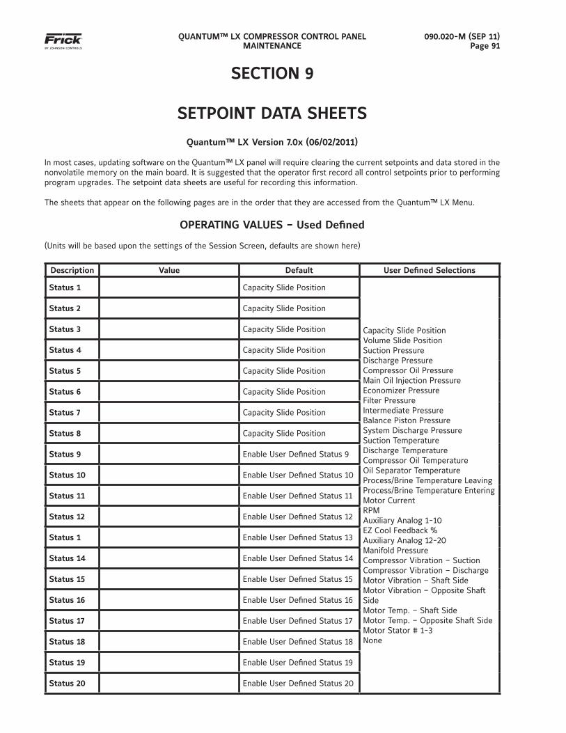
QUANTUM™ LX COMPRESSOR CONTROL PANELMAINTENANCE
090.020-M (SEP 11)Page 91
SECTION 9
SETPOINT DATA SHEETS
Quantum™ LX Version 7.0x (06/02/2011)
In most cases, updating software on the Quantum™ LX panel will require clearing the current setpoints and data stored in the nonvolatile memory on the main board. It is suggested that the operator fi rst record all control setpoints prior to performing program upgrades. The setpoint data sheets are useful for recording this information.
The sheets that appear on the following pages are in the order that they are accessed from the Quantum™ LX Menu.
OPERATING VALUES – Used Defi ned
(Units will be based upon the settings of the Session Screen, defaults are shown here)
Description Value Default User Defi ned Selections
Status 1 Capacity Slide Position
Capacity Slide PositionVolume Slide PositionSuction PressureDischarge PressureCompressor Oil PressureMain Oil Injection PressureEconomizer PressureFilter PressureIntermediate PressureBalance Piston PressureSystem Discharge PressureSuction TemperatureDischarge TemperatureCompressor Oil TemperatureOil Separator TemperatureProcess/Brine Temperature LeavingProcess/Brine Temperature EnteringMotor CurrentRPMAuxiliary Analog 1-10EZ Cool Feedback %Auxiliary Analog 12-20Manifold PressureCompressor Vibration – SuctionCompressor Vibration – DischargeMotor Vibration – Shaft SideMotor Vibration – Opposite Shaft SideMotor Temp. – Shaft SideMotor Temp. – Opposite Shaft SideMotor Stator # 1-3None
Status 2 Capacity Slide Position
Status 3 Capacity Slide Position
Status 4 Capacity Slide Position
Status 5 Capacity Slide Position
Status 6 Capacity Slide Position
Status 7 Capacity Slide Position
Status 8 Capacity Slide Position
Status 9 Enable User Defi ned Status 9
Status 10 Enable User Defi ned Status 10
Status 11 Enable User Defi ned Status 11
Status 12 Enable User Defi ned Status 12
Status 1 Enable User Defi ned Status 13
Status 14 Enable User Defi ned Status 14
Status 15 Enable User Defi ned Status 15
Status 16 Enable User Defi ned Status 16
Status 17 Enable User Defi ned Status 17
Status 18 Enable User Defi ned Status 18
Status 19 Enable User Defi ned Status 19
Status 20 Enable User Defi ned Status 20
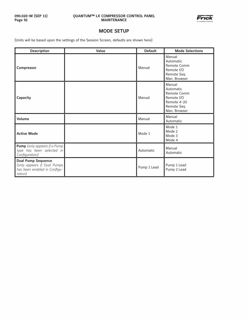
QUANTUM™ LX COMPRESSOR CONTROL PANELMAINTENANCE
090.020-M (SEP 11)Page 92
MODE SETUP
(Units will be based upon the settings of the Session Screen, defaults are shown here)
Description Value Default Mode Selections
Compressor Manual
ManualAutomaticRemote CommRemote I/ORemote SeqMan. Browser
Capacity Manual
ManualAutomaticRemote CommRemote I/ORemote 4-20Remote SeqMan. Browser
Volume ManualManualAutomatic
Active Mode Mode 1
Mode 1Mode 2Mode 3Mode 4
Pump (only appears if a Pump type has been selected in Confi guration)
AutomaticManualAutomatic
Dual Pump Sequence(only appears if Dual Pumps has been enabled in Confi gu-ration)
Pump 1 LeadPump 1 LeadPump 2 Lead
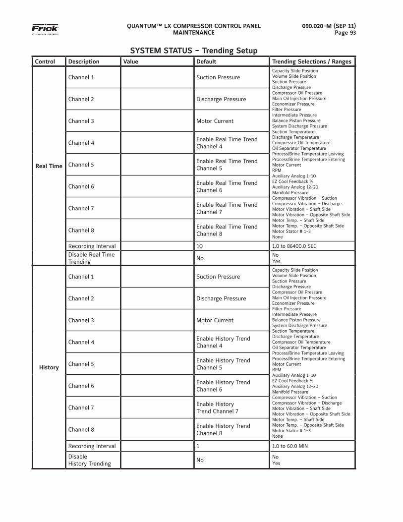
QUANTUM™ LX COMPRESSOR CONTROL PANELMAINTENANCE
090.020-M (SEP 11)Page 93
SYSTEM STATUS – Trending SetupControl Description Value Default Trending Selections / Ranges
Real Time
Channel 1 Suction PressureCapacity Slide PositionVolume Slide PositionSuction PressureDischarge PressureCompressor Oil PressureMain Oil Injection PressureEconomizer PressureFilter PressureIntermediate PressureBalance Piston PressureSystem Discharge PressureSuction TemperatureDischarge TemperatureCompressor Oil TemperatureOil Separator TemperatureProcess/Brine Temperature LeavingProcess/Brine Temperature EnteringMotor CurrentRPMAuxiliary Analog 1-10EZ Cool Feedback %Auxiliary Analog 12-20Manifold PressureCompressor Vibration – SuctionCompressor Vibration – DischargeMotor Vibration – Shaft SideMotor Vibration – Opposite Shaft SideMotor Temp. – Shaft SideMotor Temp. – Opposite Shaft SideMotor Stator # 1-3None
Channel 2 Discharge Pressure
Channel 3 Motor Current
Channel 4Enable Real Time Trend Channel 4
Channel 5Enable Real Time Trend Channel 5
Channel 6Enable Real Time Trend Channel 6
Channel 7Enable Real Time Trend Channel 7
Channel 8Enable Real Time Trend Channel 8
Recording Interval 10 1.0 to 86400.0 SEC
Disable Real Time Trending
No NoYes
History
Channel 1 Suction PressureCapacity Slide PositionVolume Slide PositionSuction PressureDischarge PressureCompressor Oil PressureMain Oil Injection PressureEconomizer PressureFilter PressureIntermediate PressureBalance Piston PressureSystem Discharge PressureSuction TemperatureDischarge TemperatureCompressor Oil TemperatureOil Separator TemperatureProcess/Brine Temperature LeavingProcess/Brine Temperature EnteringMotor CurrentRPMAuxiliary Analog 1-10EZ Cool Feedback %Auxiliary Analog 12-20Manifold PressureCompressor Vibration – SuctionCompressor Vibration – DischargeMotor Vibration – Shaft SideMotor Vibration – Opposite Shaft SideMotor Temp. – Shaft SideMotor Temp. – Opposite Shaft SideMotor Stator # 1-3None
Channel 2 Discharge Pressure
Channel 3 Motor Current
Channel 4Enable History Trend Channel 4
Channel 5Enable History Trend Channel 5
Channel 6Enable History Trend Channel 6
Channel 7Enable HistoryTrend Channel 7
Channel 8Enable History Trend Channel 8
Recording Interval 1 1.0 to 60.0 MIN
DisableHistory Trending
No NoYes
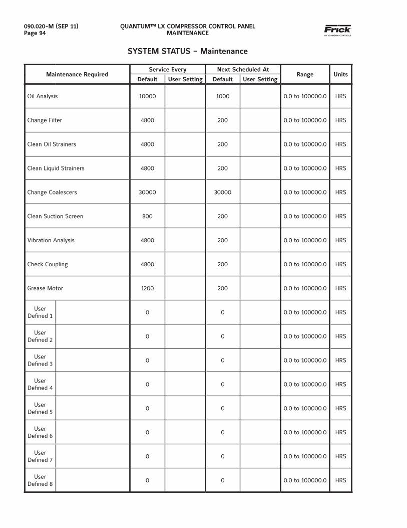
QUANTUM™ LX COMPRESSOR CONTROL PANELMAINTENANCE
090.020-M (SEP 11)Page 94
SYSTEM STATUS – Maintenance
Maintenance RequiredService Every Next Scheduled At
Range UnitsDefault User Setting Default User Setting
Oil Analysis 10000 1000 0.0 to 100000.0 HRS
Change Filter 4800 200 0.0 to 100000.0 HRS
Clean Oil Strainers 4800 200 0.0 to 100000.0 HRS
Clean Liquid Strainers 4800 200 0.0 to 100000.0 HRS
Change Coalescers 30000 30000 0.0 to 100000.0 HRS
Clean Suction Screen 800 200 0.0 to 100000.0 HRS
Vibration Analysis 4800 200 0.0 to 100000.0 HRS
Check Coupling 4800 200 0.0 to 100000.0 HRS
Grease Motor 1200 200 0.0 to 100000.0 HRS
UserDefi ned 1
0 0 0.0 to 100000.0 HRS
UserDefi ned 2
0 0 0.0 to 100000.0 HRS
UserDefi ned 3
0 0 0.0 to 100000.0 HRS
UserDefi ned 4
0 0 0.0 to 100000.0 HRS
UserDefi ned 5
0 0 0.0 to 100000.0 HRS
UserDefi ned 6
0 0 0.0 to 100000.0 HRS
UserDefi ned 7
0 0 0.0 to 100000.0 HRS
UserDefi ned 8
0 0 0.0 to 100000.0 HRS
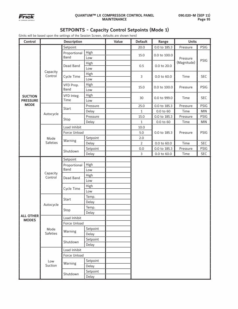
QUANTUM™ LX COMPRESSOR CONTROL PANELMAINTENANCE
090.020-M (SEP 11)Page 95
SETPOINTS - Capacity Control Setpoints (Mode 1)(Units will be based upon the settings of the Session Screen, defaults are shown here)
Control Description Value Default Range Units
SUCTION PRESSURE
MODE
Capacity Control
Setpoint 20.0 0.0 to 185.3 Pressure PSIG
Proportional Band
High15.0 0.0 to 100.0
Pressure (Magnitude)
PSIGLow
Dead BandHigh
0.5 0.0 to 20.0Low
Cycle TimeHigh
3 0.0 to 60.0 Time SECLow
VFD Prop. Band
High15.0 0.0 to 100.0 Pressure PSIG
Low
VFD Integ. Time
High30 0.0 to 999.0 Time SEC
Low
Autocycle
StartPressure 25.0 0.0 to 185.3 Pressure PSIG
Delay 1 0.0 to 60 Time MIN
StopPressure 15.0 0.0 to 185.3 Pressure PSIG
Delay 1 0.0 to 60 Time MIN
Mode Safeties
Load Inhibit 10.0
0.0 to 185.3 Pressure PSIGForce Unload 5.0
WarningSetpoint 2.0
Delay 2 0.0 to 60.0 Time SEC
ShutdownSetpoint 0.0 0.0 to 185.3 Pressure PSIG
Delay 3 0.0 to 60.0 Time SEC
ALL OTHERMODES
Capacity Control
Setpoint
Proportional Band
High
Low
Dead BandHigh
Low
Cycle TimeHigh
Low
Autocycle
StartTemp.
Delay
StopTemp.
Delay
ModeSafeties
Load Inhibit
Force Unload
WarningSetpoint
Delay
ShutdownSetpoint
Delay
LowSuction
Load Inhibit
Force Unload
WarningSetpoint
Delay
ShutdownSetpoint
Delay
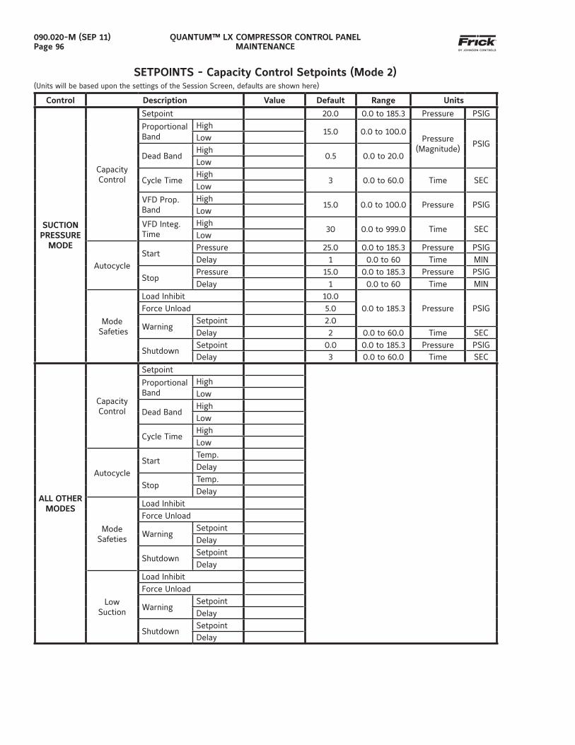
QUANTUM™ LX COMPRESSOR CONTROL PANELMAINTENANCE
090.020-M (SEP 11)Page 96
SETPOINTS - Capacity Control Setpoints (Mode 2)(Units will be based upon the settings of the Session Screen, defaults are shown here)
Control Description Value Default Range Units
SUCTION PRESSURE
MODE
Capacity Control
Setpoint 20.0 0.0 to 185.3 Pressure PSIG
Proportional Band
High15.0 0.0 to 100.0
Pressure (Magnitude)
PSIGLow
Dead BandHigh
0.5 0.0 to 20.0Low
Cycle TimeHigh
3 0.0 to 60.0 Time SECLow
VFD Prop. Band
High15.0 0.0 to 100.0 Pressure PSIG
Low
VFD Integ. Time
High30 0.0 to 999.0 Time SEC
Low
AutocycleStart
Pressure 25.0 0.0 to 185.3 Pressure PSIGDelay 1 0.0 to 60 Time MIN
StopPressure 15.0 0.0 to 185.3 Pressure PSIGDelay 1 0.0 to 60 Time MIN
Mode Safeties
Load Inhibit 10.00.0 to 185.3 Pressure PSIGForce Unload 5.0
WarningSetpoint 2.0Delay 2 0.0 to 60.0 Time SEC
ShutdownSetpoint 0.0 0.0 to 185.3 Pressure PSIGDelay 3 0.0 to 60.0 Time SEC
ALL OTHERMODES
Capacity Control
Setpoint
Proportional Band
HighLow
Dead BandHighLow
Cycle TimeHighLow
AutocycleStart
Temp.Delay
StopTemp.Delay
ModeSafeties
Load InhibitForce Unload
WarningSetpoint Delay
ShutdownSetpointDelay
LowSuction
Load InhibitForce Unload
WarningSetpointDelay
ShutdownSetpoint Delay
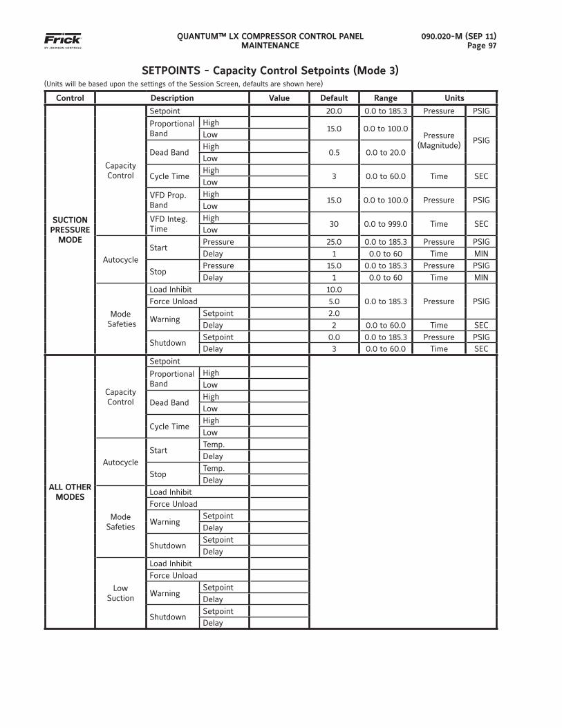
QUANTUM™ LX COMPRESSOR CONTROL PANELMAINTENANCE
090.020-M (SEP 11)Page 97
SETPOINTS - Capacity Control Setpoints (Mode 3)(Units will be based upon the settings of the Session Screen, defaults are shown here)
Control Description Value Default Range Units
SUCTION PRESSURE
MODE
Capacity Control
Setpoint 20.0 0.0 to 185.3 Pressure PSIG
Proportional Band
High15.0 0.0 to 100.0
Pressure (Magnitude)
PSIGLow
Dead BandHigh
0.5 0.0 to 20.0Low
Cycle TimeHigh
3 0.0 to 60.0 Time SECLow
VFD Prop. Band
High15.0 0.0 to 100.0 Pressure PSIG
Low
VFD Integ. Time
High30 0.0 to 999.0 Time SEC
Low
AutocycleStart
Pressure 25.0 0.0 to 185.3 Pressure PSIGDelay 1 0.0 to 60 Time MIN
StopPressure 15.0 0.0 to 185.3 Pressure PSIGDelay 1 0.0 to 60 Time MIN
Mode Safeties
Load Inhibit 10.00.0 to 185.3 Pressure PSIGForce Unload 5.0
WarningSetpoint 2.0Delay 2 0.0 to 60.0 Time SEC
ShutdownSetpoint 0.0 0.0 to 185.3 Pressure PSIGDelay 3 0.0 to 60.0 Time SEC
ALL OTHERMODES
Capacity Control
Setpoint
Proportional Band
HighLow
Dead BandHighLow
Cycle TimeHighLow
AutocycleStart
Temp.Delay
StopTemp.Delay
ModeSafeties
Load InhibitForce Unload
WarningSetpoint Delay
ShutdownSetpointDelay
LowSuction
Load InhibitForce Unload
WarningSetpointDelay
ShutdownSetpoint Delay
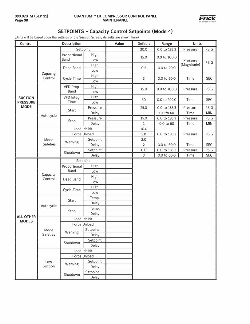
QUANTUM™ LX COMPRESSOR CONTROL PANELMAINTENANCE
090.020-M (SEP 11)Page 98
SETPOINTS - Capacity Control Setpoints (Mode 4)(Units will be based upon the settings of the Session Screen, defaults are shown here)
Control Description Value Default Range Units
SUCTION PRESSURE
MODE
Capacity Control
Setpoint 20.0 0.0 to 185.3 Pressure PSIG
Proportional Band
High15.0 0.0 to 100.0
Pressure (Magnitude)
PSIGLow
Dead BandHigh
0.5 0.0 to 20.0Low
Cycle TimeHigh
3 0.0 to 60.0 Time SECLow
VFD Prop. Band
High15.0 0.0 to 100.0 Pressure PSIG
Low
VFD Integ. Time
High30 0.0 to 999.0 Time SEC
Low
AutocycleStart
Pressure 25.0 0.0 to 185.3 Pressure PSIGDelay 1 0.0 to 60 Time MIN
StopPressure 15.0 0.0 to 185.3 Pressure PSIG
Delay 1 0.0 to 60 Time MIN
Mode Safeties
Load Inhibit 10.00.0 to 185.3 Pressure PSIGForce Unload 5.0
WarningSetpoint 2.0
Delay 2 0.0 to 60.0 Time SEC
ShutdownSetpoint 0.0 0.0 to 185.3 Pressure PSIG
Delay 3 0.0 to 60.0 Time SEC
ALL OTHERMODES
Capacity Control
Setpoint
Proportional Band
HighLow
Dead BandHighLow
Cycle TimeHighLow
AutocycleStart
Temp.Delay
StopTemp.Delay
ModeSafeties
Load InhibitForce Unload
WarningSetpoint
Delay
ShutdownSetpoint
Delay
LowSuction
Load InhibitForce Unload
WarningSetpoint
Delay
ShutdownSetpoint
Delay
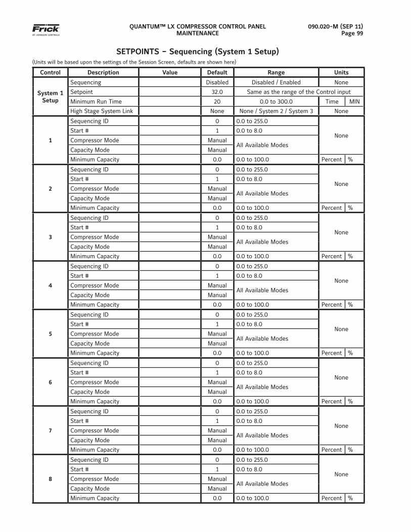
QUANTUM™ LX COMPRESSOR CONTROL PANELMAINTENANCE
090.020-M (SEP 11)Page 99
SETPOINTS – Sequencing (System 1 Setup)(Units will be based upon the settings of the Session Screen, defaults are shown here)
Control Description Value Default Range Units
System 1 Setup
Sequencing Disabled Disabled / Enabled None
Setpoint 32.0 Same as the range of the Control input
Minimum Run Time 20 0.0 to 300.0 Time MIN
High Stage System Link None None / System 2 / System 3 None
1
Sequencing ID 0 0.0 to 255.0
NoneStart # 1 0.0 to 8.0
Compressor Mode ManualAll Available Modes
Capacity Mode Manual
Minimum Capacity 0.0 0.0 to 100.0 Percent %
2
Sequencing ID 0 0.0 to 255.0
NoneStart # 1 0.0 to 8.0
Compressor Mode ManualAll Available Modes
Capacity Mode Manual
Minimum Capacity 0.0 0.0 to 100.0 Percent %
3
Sequencing ID 0 0.0 to 255.0
NoneStart # 1 0.0 to 8.0
Compressor Mode ManualAll Available Modes
Capacity Mode Manual
Minimum Capacity 0.0 0.0 to 100.0 Percent %
4
Sequencing ID 0 0.0 to 255.0
NoneStart # 1 0.0 to 8.0
Compressor Mode ManualAll Available Modes
Capacity Mode Manual
Minimum Capacity 0.0 0.0 to 100.0 Percent %
5
Sequencing ID 0 0.0 to 255.0
NoneStart # 1 0.0 to 8.0
Compressor Mode ManualAll Available Modes
Capacity Mode Manual
Minimum Capacity 0.0 0.0 to 100.0 Percent %
6
Sequencing ID 0 0.0 to 255.0
NoneStart # 1 0.0 to 8.0
Compressor Mode ManualAll Available Modes
Capacity Mode Manual
Minimum Capacity 0.0 0.0 to 100.0 Percent %
7
Sequencing ID 0 0.0 to 255.0
NoneStart # 1 0.0 to 8.0
Compressor Mode ManualAll Available Modes
Capacity Mode Manual
Minimum Capacity 0.0 0.0 to 100.0 Percent %
8
Sequencing ID 0 0.0 to 255.0
NoneStart # 1 0.0 to 8.0
Compressor Mode ManualAll Available Modes
Capacity Mode Manual
Minimum Capacity 0.0 0.0 to 100.0 Percent %
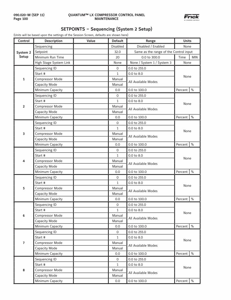
QUANTUM™ LX COMPRESSOR CONTROL PANELMAINTENANCE
090.020-M (SEP 11)Page 100
SETPOINTS – Sequencing (System 2 Setup)(Units will be based upon the settings of the Session Screen, defaults are shown here)
Control Description Value Default Range Units
System 2 Setup
Sequencing Disabled Disabled / Enabled None
Setpoint 32.0 Same as the range of the Control input
Minimum Run Time 20 0.0 to 300.0 Time MIN
High Stage System Link None None / System 1 / System 3 None
1
Sequencing ID 0 0.0 to 255.0
NoneStart # 1 0.0 to 8.0
Compressor Mode ManualAll Available Modes
Capacity Mode Manual
Minimum Capacity 0.0 0.0 to 100.0 Percent %
2
Sequencing ID 0 0.0 to 255.0
NoneStart # 1 0.0 to 8.0
Compressor Mode ManualAll Available Modes
Capacity Mode Manual
Minimum Capacity 0.0 0.0 to 100.0 Percent %
3
Sequencing ID 0 0.0 to 255.0
NoneStart # 1 0.0 to 8.0
Compressor Mode ManualAll Available Modes
Capacity Mode Manual
Minimum Capacity 0.0 0.0 to 100.0 Percent %
4
Sequencing ID 0 0.0 to 255.0
NoneStart # 1 0.0 to 8.0
Compressor Mode ManualAll Available Modes
Capacity Mode Manual
Minimum Capacity 0.0 0.0 to 100.0 Percent %
5
Sequencing ID 0 0.0 to 255.0
NoneStart # 1 0.0 to 8.0
Compressor Mode ManualAll Available Modes
Capacity Mode Manual
Minimum Capacity 0.0 0.0 to 100.0 Percent %
6
Sequencing ID 0 0.0 to 255.0
NoneStart # 1 0.0 to 8.0
Compressor Mode ManualAll Available Modes
Capacity Mode Manual
Minimum Capacity 0.0 0.0 to 100.0 Percent %
7
Sequencing ID 0 0.0 to 255.0
NoneStart # 1 0.0 to 8.0
Compressor Mode ManualAll Available Modes
Capacity Mode Manual
Minimum Capacity 0.0 0.0 to 100.0 Percent %
8
Sequencing ID 0 0.0 to 255.0
NoneStart # 1 0.0 to 8.0
Compressor Mode ManualAll Available Modes
Capacity Mode Manual
Minimum Capacity 0.0 0.0 to 100.0 Percent %
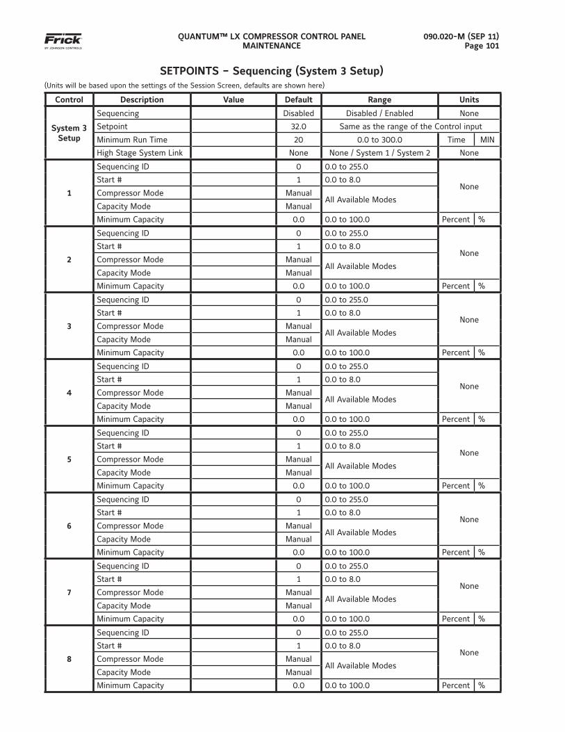
QUANTUM™ LX COMPRESSOR CONTROL PANELMAINTENANCE
090.020-M (SEP 11)Page 101
SETPOINTS – Sequencing (System 3 Setup)(Units will be based upon the settings of the Session Screen, defaults are shown here)
Control Description Value Default Range Units
System 3 Setup
Sequencing Disabled Disabled / Enabled None
Setpoint 32.0 Same as the range of the Control input
Minimum Run Time 20 0.0 to 300.0 Time MIN
High Stage System Link None None / System 1 / System 2 None
1
Sequencing ID 0 0.0 to 255.0
NoneStart # 1 0.0 to 8.0
Compressor Mode ManualAll Available Modes
Capacity Mode Manual
Minimum Capacity 0.0 0.0 to 100.0 Percent %
2
Sequencing ID 0 0.0 to 255.0
NoneStart # 1 0.0 to 8.0
Compressor Mode ManualAll Available Modes
Capacity Mode Manual
Minimum Capacity 0.0 0.0 to 100.0 Percent %
3
Sequencing ID 0 0.0 to 255.0
NoneStart # 1 0.0 to 8.0
Compressor Mode ManualAll Available Modes
Capacity Mode Manual
Minimum Capacity 0.0 0.0 to 100.0 Percent %
4
Sequencing ID 0 0.0 to 255.0
NoneStart # 1 0.0 to 8.0
Compressor Mode ManualAll Available Modes
Capacity Mode Manual
Minimum Capacity 0.0 0.0 to 100.0 Percent %
5
Sequencing ID 0 0.0 to 255.0
NoneStart # 1 0.0 to 8.0
Compressor Mode ManualAll Available Modes
Capacity Mode Manual
Minimum Capacity 0.0 0.0 to 100.0 Percent %
6
Sequencing ID 0 0.0 to 255.0
NoneStart # 1 0.0 to 8.0
Compressor Mode ManualAll Available Modes
Capacity Mode Manual
Minimum Capacity 0.0 0.0 to 100.0 Percent %
7
Sequencing ID 0 0.0 to 255.0
NoneStart # 1 0.0 to 8.0
Compressor Mode ManualAll Available Modes
Capacity Mode Manual
Minimum Capacity 0.0 0.0 to 100.0 Percent %
8
Sequencing ID 0 0.0 to 255.0
NoneStart # 1 0.0 to 8.0
Compressor Mode ManualAll Available Modes
Capacity Mode Manual
Minimum Capacity 0.0 0.0 to 100.0 Percent %
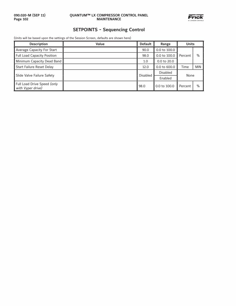
QUANTUM™ LX COMPRESSOR CONTROL PANELMAINTENANCE
090.020-M (SEP 11)Page 102
SETPOINTS - Sequencing Control
(Units will be based upon the settings of the Session Screen, defaults are shown here)
Description Value Default Range Units
Average Capacity For Start 90.0 0.0 to 100.0
Percent %Full Load Capacity Position 98.0 0.0 to 100.0
Minimum Capacity Dead Band 1.0 0.0 to 20.0
Start Failure Reset Delay 12.0 0.0 to 600.0 Time MIN
Slide Valve Failure Safety DisabledDisabled
NoneEnabled
Full Load Drive Speed (only with Vyper drive) 98.0 0.0 to 100.0 Percent %
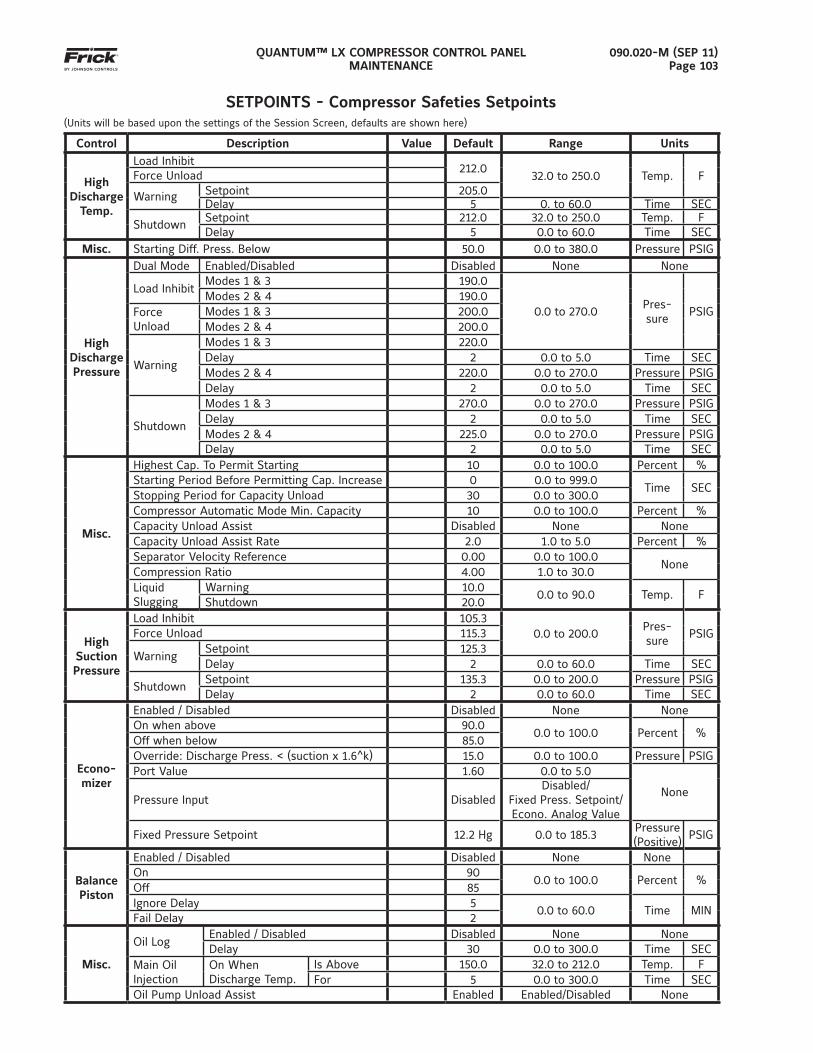
QUANTUM™ LX COMPRESSOR CONTROL PANELMAINTENANCE
090.020-M (SEP 11)Page 103
SETPOINTS - Compressor Safeties Setpoints(Units will be based upon the settings of the Session Screen, defaults are shown here)
Control Description Value Default Range Units
HighDischarge
Temp.
Load Inhibit212.0
32.0 to 250.0 Temp. FForce Unload
Warning Setpoint 205.0Delay 5 0. to 60.0 Time SEC
ShutdownSetpoint 212.0 32.0 to 250.0 Temp. FDelay 5 0.0 to 60.0 Time SEC
Misc. Starting Diff. Press. Below 50.0 0.0 to 380.0 Pressure PSIG
HighDischargePressure
Dual Mode Enabled/Disabled Disabled None None
Load InhibitModes 1 & 3 190.0
0.0 to 270.0Pres-sure
PSIGModes 2 & 4 190.0
ForceUnload
Modes 1 & 3 200.0Modes 2 & 4 200.0
Warning
Modes 1 & 3 220.0Delay 2 0.0 to 5.0 Time SECModes 2 & 4 220.0 0.0 to 270.0 Pressure PSIGDelay 2 0.0 to 5.0 Time SEC
Shutdown
Modes 1 & 3 270.0 0.0 to 270.0 Pressure PSIGDelay 2 0.0 to 5.0 Time SECModes 2 & 4 225.0 0.0 to 270.0 Pressure PSIGDelay 2 0.0 to 5.0 Time SEC
Misc.
Highest Cap. To Permit Starting 10 0.0 to 100.0 Percent %Starting Period Before Permitting Cap. Increase 0 0.0 to 999.0
Time SECStopping Period for Capacity Unload 30 0.0 to 300.0Compressor Automatic Mode Min. Capacity 10 0.0 to 100.0 Percent %Capacity Unload Assist Disabled None NoneCapacity Unload Assist Rate 2.0 1.0 to 5.0 Percent %Separator Velocity Reference 0.00 0.0 to 100.0
NoneCompression Ratio 4.00 1.0 to 30.0LiquidSlugging
Warning 10.00.0 to 90.0 Temp. F
Shutdown 20.0
High Suction Pressure
Load Inhibit 105.30.0 to 200.0
Pres-sure
PSIGForce Unload 115.3
WarningSetpoint 125.3Delay 2 0.0 to 60.0 Time SEC
ShutdownSetpoint 135.3 0.0 to 200.0 Pressure PSIGDelay 2 0.0 to 60.0 Time SEC
Econo-mizer
Enabled / Disabled Disabled None NoneOn when above 90.0
0.0 to 100.0 Percent %Off when below 85.0Override: Discharge Press. < (suction x 1.6^k) 15.0 0.0 to 100.0 Pressure PSIGPort Value 1.60 0.0 to 5.0
NonePressure Input Disabled
Disabled/Fixed Press. Setpoint/Econo. Analog Value
Fixed Pressure Setpoint 12.2 Hg 0.0 to 185.3Pressure (Positive)
PSIG
Balance Piston
Enabled / Disabled Disabled None NoneOn 90
0.0 to 100.0 Percent %Off 85Ignore Delay 5
0.0 to 60.0 Time MINFail Delay 2
Misc.
Oil LogEnabled / Disabled Disabled None NoneDelay 30 0.0 to 300.0 Time SEC
Main Oil Injection
On WhenDischarge Temp.
Is Above 150.0 32.0 to 212.0 Temp. FFor 5 0.0 to 300.0 Time SEC
Oil Pump Unload Assist Enabled Enabled/Disabled None
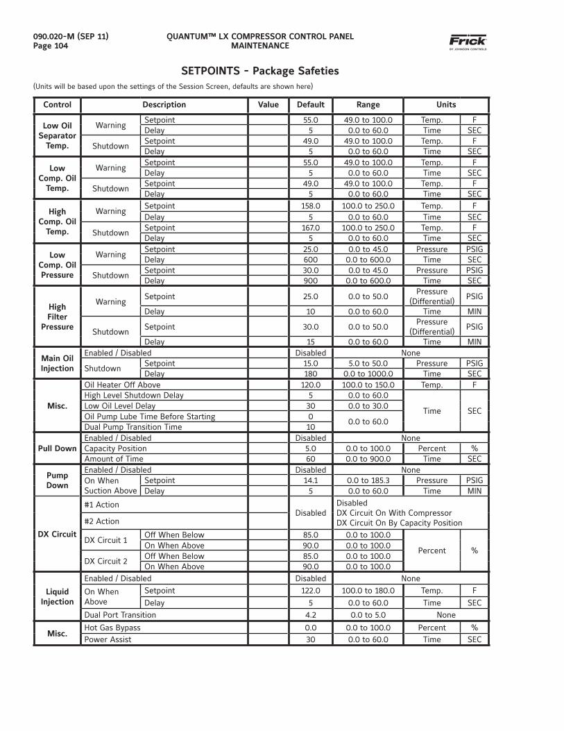
QUANTUM™ LX COMPRESSOR CONTROL PANELMAINTENANCE
090.020-M (SEP 11)Page 104
Control Description Value Default Range Units
Low Oil Separator
Temp.
WarningSetpoint 55.0 49.0 to 100.0 Temp. FDelay 5 0.0 to 60.0 Time SEC
ShutdownSetpoint 49.0 49.0 to 100.0 Temp. FDelay 5 0.0 to 60.0 Time SEC
Low Comp. Oil
Temp.
WarningSetpoint 55.0 49.0 to 100.0 Temp. FDelay 5 0.0 to 60.0 Time SEC
ShutdownSetpoint 49.0 49.0 to 100.0 Temp. FDelay 5 0.0 to 60.0 Time SEC
High Comp. Oil
Temp.
WarningSetpoint 158.0 100.0 to 250.0 Temp. FDelay 5 0.0 to 60.0 Time SEC
ShutdownSetpoint 167.0 100.0 to 250.0 Temp. FDelay 5 0.0 to 60.0 Time SEC
Low Comp. Oil Pressure
WarningSetpoint 25.0 0.0 to 45.0 Pressure PSIGDelay 600 0.0 to 600.0 Time SEC
ShutdownSetpoint 30.0 0.0 to 45.0 Pressure PSIGDelay 900 0.0 to 600.0 Time SEC
High Filter
Pressure
WarningSetpoint 25.0 0.0 to 50.0
Pressure (Differential)
PSIG
Delay 10 0.0 to 60.0 Time MIN
ShutdownSetpoint 30.0 0.0 to 50.0
Pressure (Differential)
PSIG
Delay 15 0.0 to 60.0 Time MIN
Main Oil Injection
Enabled / Disabled Disabled None
ShutdownSetpoint 15.0 5.0 to 50.0 Pressure PSIGDelay 180 0.0 to 1000.0 Time SEC
Misc.
Oil Heater Off Above 120.0 100.0 to 150.0 Temp. FHigh Level Shutdown Delay 5 0.0 to 60.0
Time SECLow Oil Level Delay 30 0.0 to 30.0Oil Pump Lube Time Before Starting 0
0.0 to 60.0Dual Pump Transition Time 10
Pull DownEnabled / Disabled Disabled NoneCapacity Position 5.0 0.0 to 100.0 Percent %Amount of Time 60 0.0 to 900.0 Time SEC
Pump Down
Enabled / Disabled Disabled NoneOn WhenSuction Above
Setpoint 14.1 0.0 to 185.3 Pressure PSIGDelay 5 0.0 to 60.0 Time MIN
DX Circuit
#1 ActionDisabled
DisabledDX Circuit On With CompressorDX Circuit On By Capacity Position#2 Action
DX Circuit 1Off When Below 85.0 0.0 to 100.0
Percent %On When Above 90.0 0.0 to 100.0
DX Circuit 2Off When Below 85.0 0.0 to 100.0On When Above 90.0 0.0 to 100.0
LiquidInjection
Enabled / Disabled Disabled None
On When Above
Setpoint 122.0 100.0 to 180.0 Temp. F
Delay 5 0.0 to 60.0 Time SEC
Dual Port Transition 4.2 0.0 to 5.0 None
Misc.Hot Gas Bypass 0.0 0.0 to 100.0 Percent %Power Assist 30 0.0 to 60.0 Time SEC
SETPOINTS - Package Safeties(Units will be based upon the settings of the Session Screen, defaults are shown here)
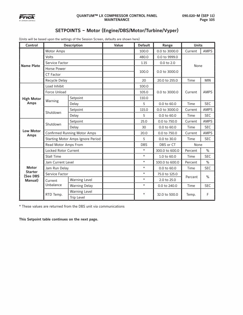
QUANTUM™ LX COMPRESSOR CONTROL PANELMAINTENANCE
090.020-M (SEP 11)Page 105
SETPOINTS – Motor (Engine/DBS/Motor/Turbine/Vyper)
(Units will be based upon the settings of the Session Screen, defaults are shown here)
Control Description Value Default Range Units
Name Plate
Motor Amps 100.0 0.0 to 3000.0 Current AMPS
Volts 480.0 0.0 to 9999.0
NoneService Factor 1.15 0.0 to 2.0
Horse Power100.0 0.0 to 3000.0
CT Factor
Recycle Delay 20 20.0 to 255.0 Time MIN
High Motor Amps
Load Inhibit 100.0
0.0 to 3000.0 Current AMPSForce Unload 105.0
WarningSetpoint 110.0
Delay 5 0.0 to 60.0 Time SEC
ShutdownSetpoint 115.0 0.0 to 3000.0 Current AMPS
Delay 5 0.0 to 60.0 Time SEC
Low Motor Amps
ShutdownSetpoint 25.0 0.0 to 750.0 Current AMPS
Delay 30 0.0 to 60.0 Time SEC
Confi rmed Running Motor Amps 20.0 0.0 to 750.0 Current AMPS
Starting Motor Amps Ignore Period 5 0.0 to 30.0 Time SEC
Read Motor Amps From DBS DBS or CT None
Motor Starter
(See DBS Manual)
Locked Rotor Current * 300.0 to 600.0 Percent %
Stall Time * 1.0 to 60.0 Time SEC
Jam Current Level * 100.0 to 600.0 Percent %
Jam Run Delay * 0.0 to 60.0 Time SEC
Service Factor * 75.0 to 125.0 Percent %
CurrentUnbalance
Warning Level * 2.0 to 25.0
Warning Delay * 0.0 to 240.0 Time SEC
RTD Temp.Warning Level
* 32.0 to 500.0 Temp. FTrip Level
* These values are returned from the DBS unit via communications
This Setpoint table continues on the next page.
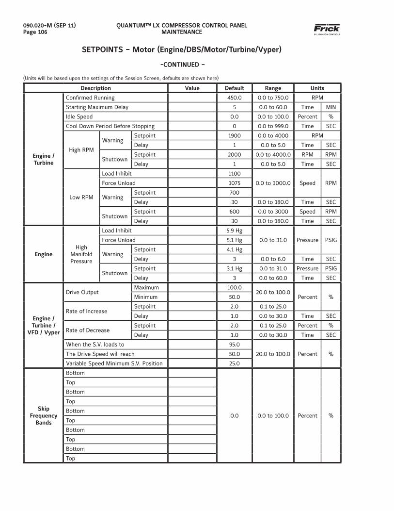
QUANTUM™ LX COMPRESSOR CONTROL PANELMAINTENANCE
090.020-M (SEP 11)Page 106
SETPOINTS – Motor (Engine/DBS/Motor/Turbine/Vyper)
-CONTINUED –
(Units will be based upon the settings of the Session Screen, defaults are shown here)
Description Value Default Range Units
Engine / Turbine
Confi rmed Running 450.0 0.0 to 750.0 RPM
Starting Maximum Delay 5 0.0 to 60.0 Time MIN
Idle Speed 0.0 0.0 to 100.0 Percent %
Cool Down Period Before Stopping 0 0.0 to 999.0 Time SEC
High RPM
WarningSetpoint 1900 0.0 to 4000 RPM
Delay 1 0.0 to 5.0 Time SEC
ShutdownSetpoint 2000 0.0 to 4000.0 RPM RPM
Delay 1 0.0 to 5.0 Time SEC
Low RPM
Load Inhibit 1100
0.0 to 3000.0 Speed RPMForce Unload 1075
WarningSetpoint 700
Delay 30 0.0 to 180.0 Time SEC
ShutdownSetpoint 600 0.0 to 3000 Speed RPM
Delay 30 0.0 to 180.0 Time SEC
EngineHigh
Manifold Pressure
Load Inhibit 5.9 Hg
0.0 to 31.0 Pressure PSIGForce Unload 5.1 Hg
WarningSetpoint 4.1 Hg
Delay 3 0.0 to 6.0 Time SEC
ShutdownSetpoint 3.1 Hg 0.0 to 31.0 Pressure PSIG
Delay 3 0.0 to 60.0 Time SEC
Engine / Turbine /
VFD / Vyper
Drive OutputMaximum 100.0
20.0 to 100.0Percent %Minimum 50.0
Rate of IncreaseSetpoint 2.0 0.1 to 25.0
Delay 1.0 0.0 to 30.0 Time SEC
Rate of DecreaseSetpoint 2.0 0.1 to 25.0 Percent %
Delay 1.0 0.0 to 30.0 Time SEC
When the S.V. loads to 95.0
20.0 to 100.0 Percent %The Drive Speed will reach 50.0
Variable Speed Minimum S.V. Position 25.0
SkipFrequency
Bands
Bottom
0.0 0.0 to 100.0 Percent %
Top
Bottom
Top
Bottom
Top
Bottom
Top
Bottom
Top
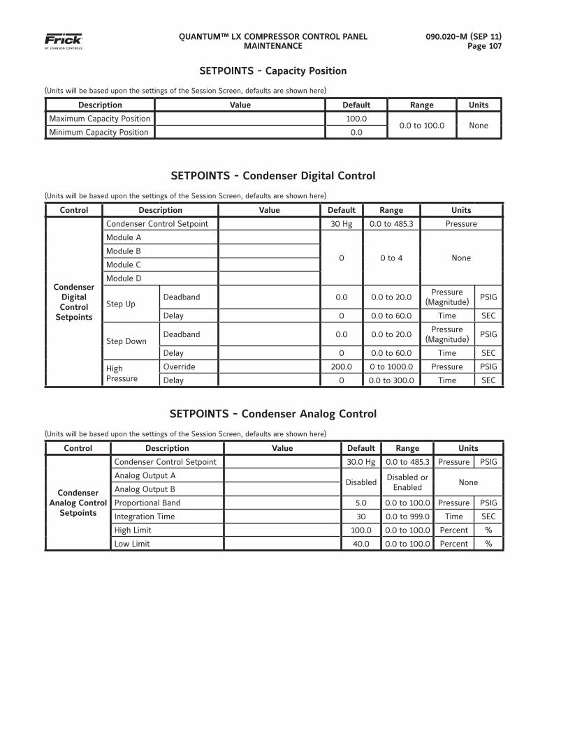
QUANTUM™ LX COMPRESSOR CONTROL PANELMAINTENANCE
090.020-M (SEP 11)Page 107
SETPOINTS - Capacity Position
(Units will be based upon the settings of the Session Screen, defaults are shown here)
Description Value Default Range Units
Maximum Capacity Position 100.00.0 to 100.0 None
Minimum Capacity Position 0.0
SETPOINTS - Condenser Digital Control
(Units will be based upon the settings of the Session Screen, defaults are shown here)
Control Description Value Default Range Units
Condenser DigitalControl
Setpoints
Condenser Control Setpoint 30 Hg 0.0 to 485.3 Pressure
Module A
0 0 to 4 NoneModule B
Module C
Module D
Step UpDeadband 0.0 0.0 to 20.0
Pressure (Magnitude)
PSIG
Delay 0 0.0 to 60.0 Time SEC
Step DownDeadband 0.0 0.0 to 20.0
Pressure (Magnitude)
PSIG
Delay 0 0.0 to 60.0 Time SEC
HighPressure
Override 200.0 0 to 1000.0 Pressure PSIG
Delay 0 0.0 to 300.0 Time SEC
SETPOINTS - Condenser Analog Control
(Units will be based upon the settings of the Session Screen, defaults are shown here)
Control Description Value Default Range Units
Condenser Analog Control
Setpoints
Condenser Control Setpoint 30.0 Hg 0.0 to 485.3 Pressure PSIG
Analog Output ADisabled
Disabled or Enabled
NoneAnalog Output B
Proportional Band 5.0 0.0 to 100.0 Pressure PSIG
Integration Time 30 0.0 to 999.0 Time SEC
High Limit 100.0 0.0 to 100.0 Percent %
Low Limit 40.0 0.0 to 100.0 Percent %
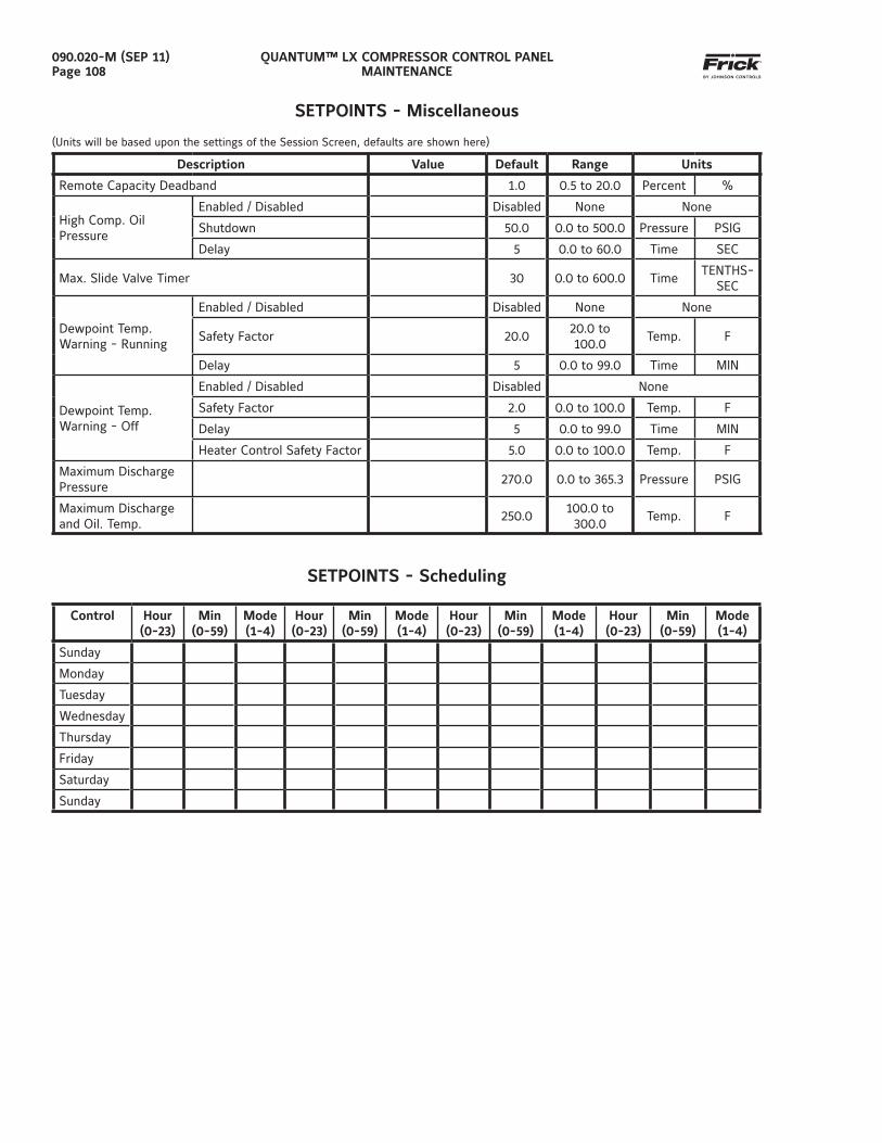
QUANTUM™ LX COMPRESSOR CONTROL PANELMAINTENANCE
090.020-M (SEP 11)Page 108
SETPOINTS - Miscellaneous
(Units will be based upon the settings of the Session Screen, defaults are shown here)
Description Value Default Range Units
Remote Capacity Deadband 1.0 0.5 to 20.0 Percent %
High Comp. OilPressure
Enabled / Disabled Disabled None None
Shutdown 50.0 0.0 to 500.0 Pressure PSIG
Delay 5 0.0 to 60.0 Time SEC
Max. Slide Valve Timer 30 0.0 to 600.0 TimeTENTHS-
SEC
Dewpoint Temp. Warning - Running
Enabled / Disabled Disabled None None
Safety Factor 20.020.0 to 100.0
Temp. F
Delay 5 0.0 to 99.0 Time MIN
Dewpoint Temp. Warning - Off
Enabled / Disabled Disabled None
Safety Factor 2.0 0.0 to 100.0 Temp. F
Delay 5 0.0 to 99.0 Time MIN
Heater Control Safety Factor 5.0 0.0 to 100.0 Temp. F
Maximum Discharge Pressure
270.0 0.0 to 365.3 Pressure PSIG
Maximum Discharge and Oil. Temp.
250.0100.0 to 300.0
Temp. F
SETPOINTS - Scheduling
Control Hour (0-23)
Min(0-59)
Mode (1-4)
Hour(0-23)
Min(0-59)
Mode(1-4)
Hour(0-23)
Min(0-59)
Mode(1-4)
Hour(0-23)
Min(0-59)
Mode(1-4)
Sunday
Monday
Tuesday
Wednesday
Thursday
Friday
Saturday
Sunday
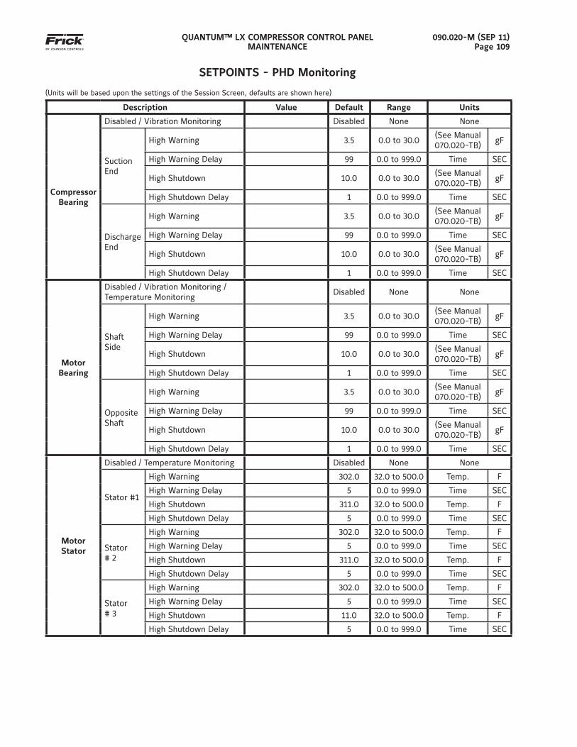
QUANTUM™ LX COMPRESSOR CONTROL PANELMAINTENANCE
090.020-M (SEP 11)Page 109
SETPOINTS - PHD Monitoring
(Units will be based upon the settings of the Session Screen, defaults are shown here)
Description Value Default Range Units
Compressor Bearing
Disabled / Vibration Monitoring Disabled None None
Suction End
High Warning 3.5 0.0 to 30.0(See Manual 070.020-TB)
gF
High Warning Delay 99 0.0 to 999.0 Time SEC
High Shutdown 10.0 0.0 to 30.0(See Manual 070.020-TB)
gF
High Shutdown Delay 1 0.0 to 999.0 Time SEC
Discharge End
High Warning 3.5 0.0 to 30.0(See Manual 070.020-TB)
gF
High Warning Delay 99 0.0 to 999.0 Time SEC
High Shutdown 10.0 0.0 to 30.0(See Manual 070.020-TB)
gF
High Shutdown Delay 1 0.0 to 999.0 Time SEC
MotorBearing
Disabled / Vibration Monitoring / Temperature Monitoring
Disabled None None
Shaft Side
High Warning 3.5 0.0 to 30.0(See Manual 070.020-TB)
gF
High Warning Delay 99 0.0 to 999.0 Time SEC
High Shutdown 10.0 0.0 to 30.0(See Manual 070.020-TB)
gF
High Shutdown Delay 1 0.0 to 999.0 Time SEC
Opposite Shaft
High Warning 3.5 0.0 to 30.0(See Manual 070.020-TB)
gF
High Warning Delay 99 0.0 to 999.0 Time SEC
High Shutdown 10.0 0.0 to 30.0(See Manual 070.020-TB)
gF
High Shutdown Delay 1 0.0 to 999.0 Time SEC
MotorStator
Disabled / Temperature Monitoring Disabled None None
Stator #1
High Warning 302.0 32.0 to 500.0 Temp. F
High Warning Delay 5 0.0 to 999.0 Time SEC
High Shutdown 311.0 32.0 to 500.0 Temp. F
High Shutdown Delay 5 0.0 to 999.0 Time SEC
Stator # 2
High Warning 302.0 32.0 to 500.0 Temp. F
High Warning Delay 5 0.0 to 999.0 Time SEC
High Shutdown 311.0 32.0 to 500.0 Temp. F
High Shutdown Delay 5 0.0 to 999.0 Time SEC
Stator # 3
High Warning 302.0 32.0 to 500.0 Temp. F
High Warning Delay 5 0.0 to 999.0 Time SEC
High Shutdown 11.0 32.0 to 500.0 Temp. F
High Shutdown Delay 5 0.0 to 999.0 Time SEC
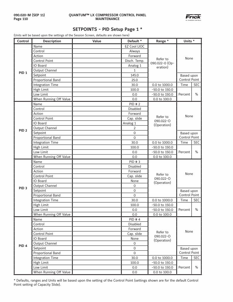
QUANTUM™ LX COMPRESSOR CONTROL PANELMAINTENANCE
090.020-M (SEP 11)Page 110
SETPOINTS - PID Setup Page 1 *(Units will be based upon the settings of the Session Screen, defaults are shown here)
Control Description Value Default * Range * Units *
PID 1
Name EZ Cool LIOC
Refer to 090.022-0 (Op-
eration)
None
Control AlwaysAction ForwardControl Point Disch. Temp.IO Board Analog 1Output Channel 1Setpoint 145.0 Based upon
Control PointProportional Band 25.0Integration Time 30.0 0.0 to 1000.0 Time SECHigh Limit 100.0 -50.0 to 150.0
Percent %Low Limit 0.0 -50.0 to 150.0When Running Off Value 0.0 0.0 to 100.0
PID 2
Name PID # 2
Refer to 090.022-O(Operation)
None
Control DisabledAction ForwardControl Point Cap. slideIO Board Analog 1 Output Channel 2Setpoint 0 Based upon
Control PointProportional Band 0Integration Time 30.0 0.0 to 1000.0 Time SECHigh Limit 100.0 -50.0 to 150.0
Percent %Low Limit 0.0 -50.0 to 150.0When Running Off Value 0.0 0.0 to 100.0
PID 3
Name PID # 3
Refer to 090.022-O (Operation)
None
Control DisabledAction ForwardControl Point Cap. slideIO Board NoneOutput Channel 0Setpoint 0 Based upon
Control PointProportional Band 0Integration Time 30.0 0.0 to 1000.0 Time SECHigh Limit 100.0 -50.0 to 150.0
Percent %Low Limit 0.0 -50.0 to 150.0When Running Off Value 0.0 0.0 to 100.0
PID 4
Name PID # 4
Refer to 090.022-O (Operation)
None
Control DisabledAction ForwardControl Point Cap. slideIO Board NoneOutput Channel 0Setpoint 0 Based upon
Control PointProportional Band 0Integration Time 30.0 0.0 to 1000.0 Time SECHigh Limit 100.0 -50.0 to 150.0
Percent %Low Limit 0.0 -50.0 to 150.0When Running Off Value 0.0 0.0 to 100.0
* Defaults, ranges and Units will be based upon the setting of the Control Point (settings shown are for the default Control Point setting of Capacity Slide).
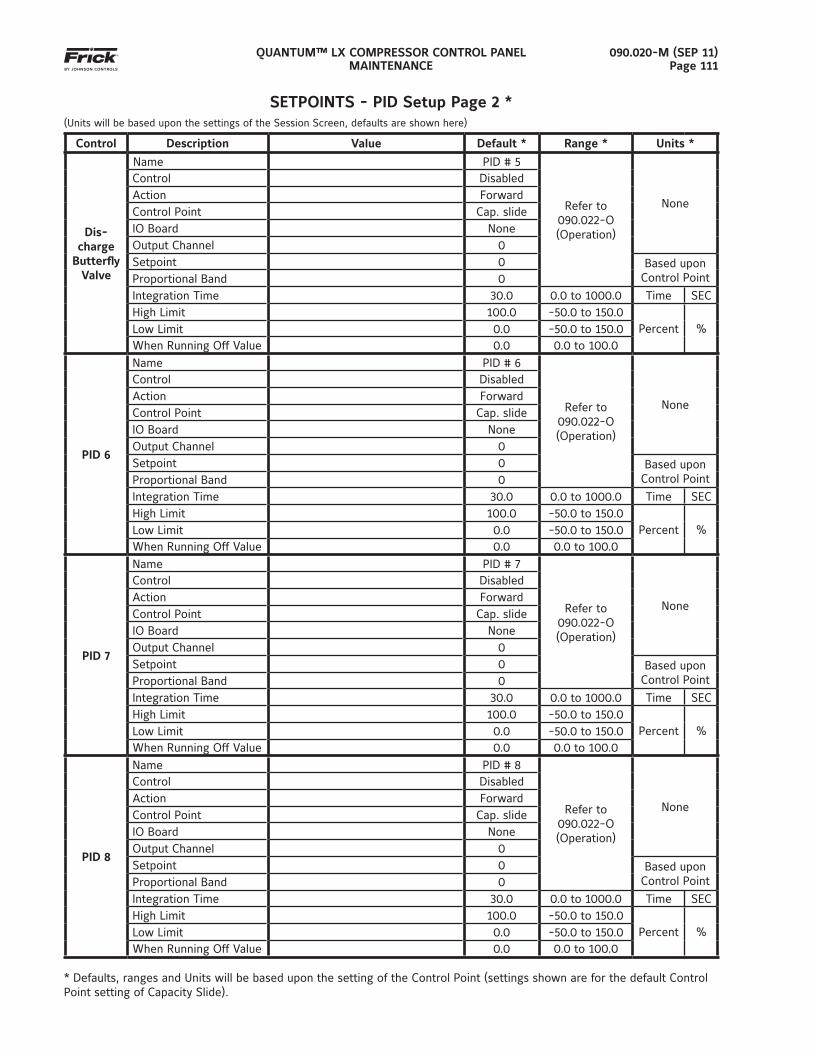
QUANTUM™ LX COMPRESSOR CONTROL PANELMAINTENANCE
090.020-M (SEP 11)Page 111
SETPOINTS - PID Setup Page 2 *(Units will be based upon the settings of the Session Screen, defaults are shown here)
Control Description Value Default * Range * Units *
Dis-charge
Butterfl y Valve
Name PID # 5
Refer to 090.022-O (Operation)
None
Control DisabledAction ForwardControl Point Cap. slideIO Board NoneOutput Channel 0Setpoint 0 Based upon
Control PointProportional Band 0Integration Time 30.0 0.0 to 1000.0 Time SECHigh Limit 100.0 -50.0 to 150.0
Percent %Low Limit 0.0 -50.0 to 150.0When Running Off Value 0.0 0.0 to 100.0
PID 6
Name PID # 6
Refer to 090.022-O(Operation)
None
Control DisabledAction ForwardControl Point Cap. slideIO Board NoneOutput Channel 0Setpoint 0 Based upon
Control PointProportional Band 0Integration Time 30.0 0.0 to 1000.0 Time SECHigh Limit 100.0 -50.0 to 150.0
Percent %Low Limit 0.0 -50.0 to 150.0When Running Off Value 0.0 0.0 to 100.0
PID 7
Name PID # 7
Refer to 090.022-O(Operation)
None
Control DisabledAction ForwardControl Point Cap. slideIO Board NoneOutput Channel 0Setpoint 0 Based upon
Control PointProportional Band 0Integration Time 30.0 0.0 to 1000.0 Time SECHigh Limit 100.0 -50.0 to 150.0
Percent %Low Limit 0.0 -50.0 to 150.0When Running Off Value 0.0 0.0 to 100.0
PID 8
Name PID # 8
Refer to 090.022-O(Operation)
None
Control DisabledAction ForwardControl Point Cap. slideIO Board NoneOutput Channel 0Setpoint 0 Based upon
Control PointProportional Band 0Integration Time 30.0 0.0 to 1000.0 Time SECHigh Limit 100.0 -50.0 to 150.0
Percent %Low Limit 0.0 -50.0 to 150.0When Running Off Value 0.0 0.0 to 100.0
* Defaults, ranges and Units will be based upon the setting of the Control Point (settings shown are for the default Control Point setting of Capacity Slide).
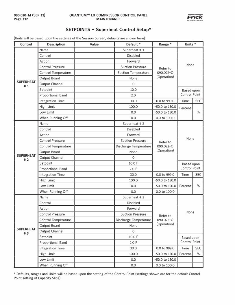
QUANTUM™ LX COMPRESSOR CONTROL PANELMAINTENANCE
090.020-M (SEP 11)Page 112
SETPOINTS – Superheat Control Setup*
(Units will be based upon the settings of the Session Screen, defaults are shown here)
Control Description Value Default * Range * Units *
SUPERHEAT # 1
Name Superheat # 1
Refer to 090.022-O(Operation)
None
Control Disabled
Action Forward
Control Pressure Suction Pressure
Control Temperature Suction Temperature
Output Board None
Output Channel 0
Setpoint 10.0 Based upon Control PointProportional Band 2.0
Integration Time 30.0 0.0 to 999.0 Time SEC
High Limit 100.0 -50.0 to 150.0 Percent
%Low Limit 0.0 -50.0 to 150.0
When Running Off 0.0 0.0 to 100.0
SUPERHEAT # 2
Name Superheat # 2
Refer to 090.022-O(Operation)
None
Control Disabled
Action Forward
Control Pressure Suction Pressure
Control Temperature Discharge Temperature
Output Board None
Output Channel 0
Setpoint 10.0 F Based upon Control PointProportional Band 2.0 F
Integration Time 30.0 0.0 to 999.0 Time SEC
High Limit 100.0 -50.0 to 150.0
Percent %Low Limit 0.0 -50.0 to 150.0
When Running Off 0.0 0.0 to 100.0
SUPERHEAT # 3
Name Superheat # 3
Refer to 090.022-O(Operation)
None
Control Disabled
Action Forward
Control Pressure Suction Pressure
Control Temperature Discharge Temperature
Output Board None
Output Channel 0
Setpoint 10.0 F Based upon Control PointProportional Band 2.0 F
Integration Time 30.0 0.0 to 999.0 Time SEC
High Limit 100.0 -50.0 to 150.0 Percent %
Low Limit 0.0 -50.0 to 150.0
When Running Off 0.0 0.0 to 100.0 * Defaults, ranges and Units will be based upon the setting of the Control Point (settings shown are for the default Control Point setting of Capacity Slide).
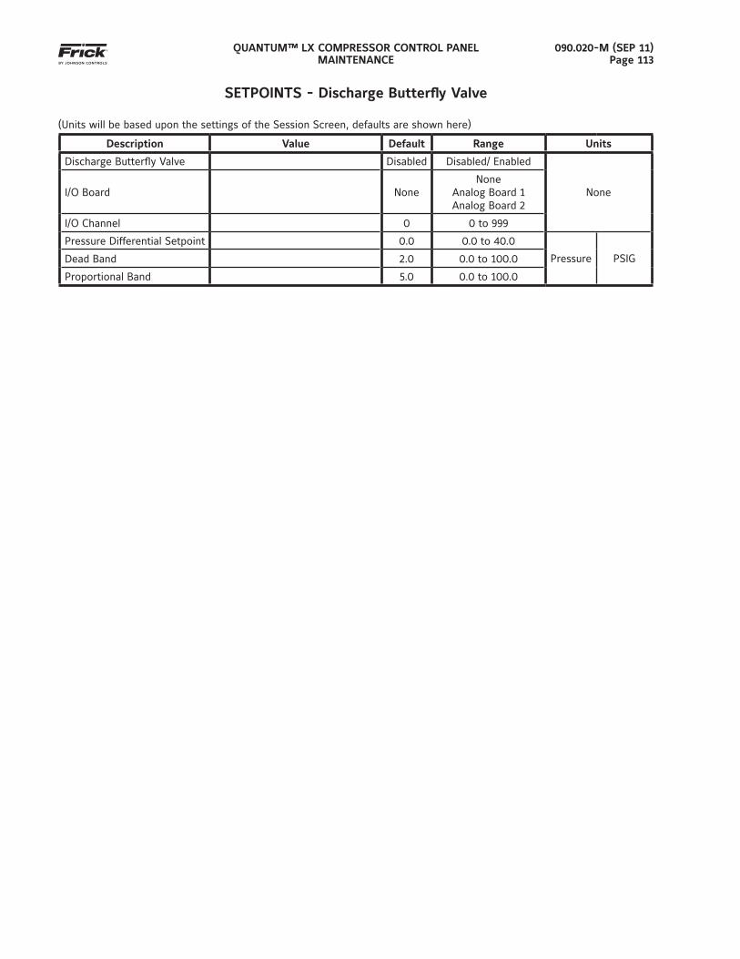
QUANTUM™ LX COMPRESSOR CONTROL PANELMAINTENANCE
090.020-M (SEP 11)Page 113
SETPOINTS - Discharge Butterfl y Valve
(Units will be based upon the settings of the Session Screen, defaults are shown here)
Description Value Default Range Units
Discharge Butterfl y Valve Disabled Disabled/ Enabled
NoneI/O Board NoneNone
Analog Board 1Analog Board 2
I/O Channel 0 0 to 999
Pressure Differential Setpoint 0.0 0.0 to 40.0
Pressure PSIGDead Band 2.0 0.0 to 100.0
Proportional Band 5.0 0.0 to 100.0
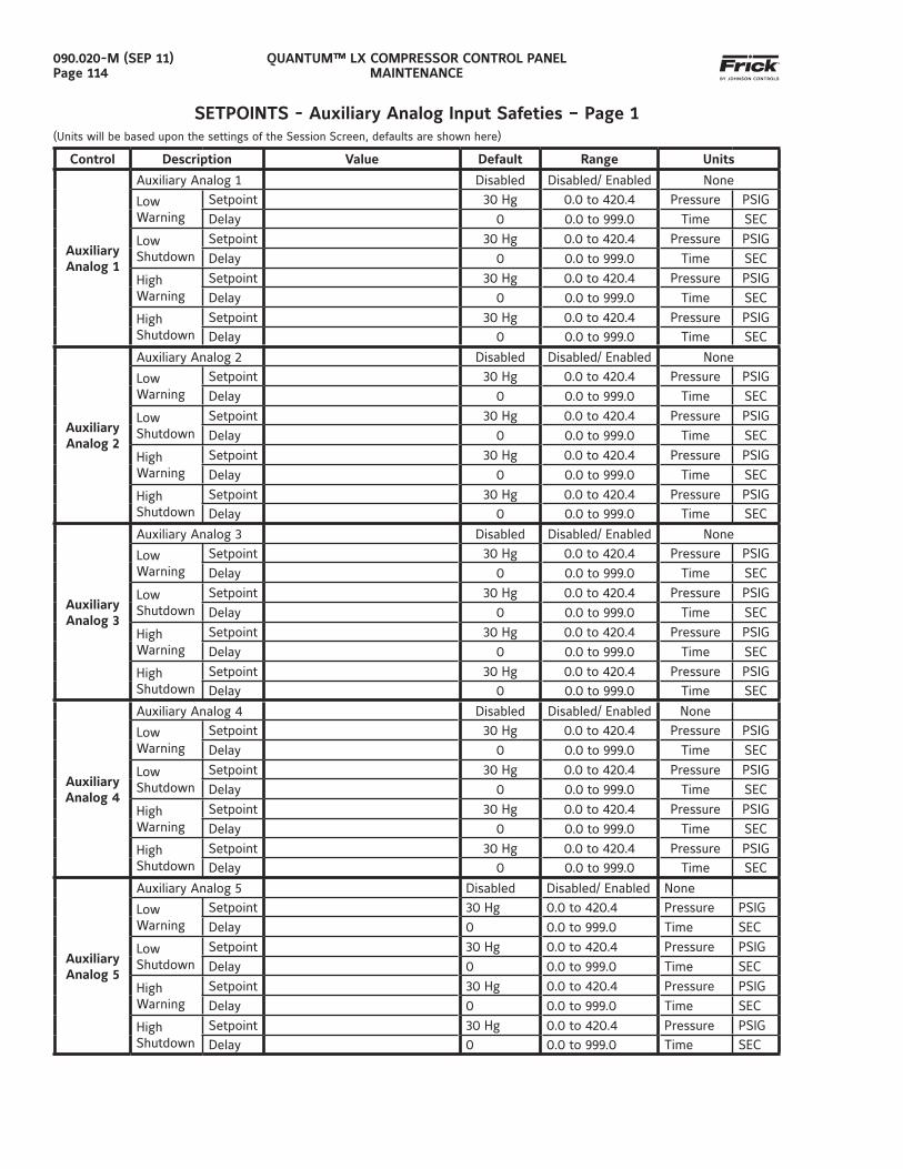
QUANTUM™ LX COMPRESSOR CONTROL PANELMAINTENANCE
090.020-M (SEP 11)Page 114
SETPOINTS - Auxiliary Analog Input Safeties – Page 1(Units will be based upon the settings of the Session Screen, defaults are shown here)
Control Description Value Default Range Units
Auxiliary Analog 1
Auxiliary Analog 1 Disabled Disabled/ Enabled None
Low Warning
Setpoint 30 Hg 0.0 to 420.4 Pressure PSIG
Delay 0 0.0 to 999.0 Time SEC
Low Shutdown
Setpoint 30 Hg 0.0 to 420.4 Pressure PSIG
Delay 0 0.0 to 999.0 Time SEC
High Warning
Setpoint 30 Hg 0.0 to 420.4 Pressure PSIG
Delay 0 0.0 to 999.0 Time SEC
High Shutdown
Setpoint 30 Hg 0.0 to 420.4 Pressure PSIG
Delay 0 0.0 to 999.0 Time SEC
Auxiliary Analog 2
Auxiliary Analog 2 Disabled Disabled/ Enabled None
Low Warning
Setpoint 30 Hg 0.0 to 420.4 Pressure PSIG
Delay 0 0.0 to 999.0 Time SEC
Low Shutdown
Setpoint 30 Hg 0.0 to 420.4 Pressure PSIG
Delay 0 0.0 to 999.0 Time SEC
High Warning
Setpoint 30 Hg 0.0 to 420.4 Pressure PSIG
Delay 0 0.0 to 999.0 Time SEC
High Shutdown
Setpoint 30 Hg 0.0 to 420.4 Pressure PSIG
Delay 0 0.0 to 999.0 Time SEC
Auxiliary Analog 3
Auxiliary Analog 3 Disabled Disabled/ Enabled None
Low Warning
Setpoint 30 Hg 0.0 to 420.4 Pressure PSIG
Delay 0 0.0 to 999.0 Time SEC
Low Shutdown
Setpoint 30 Hg 0.0 to 420.4 Pressure PSIG
Delay 0 0.0 to 999.0 Time SEC
High Warning
Setpoint 30 Hg 0.0 to 420.4 Pressure PSIG
Delay 0 0.0 to 999.0 Time SEC
High Shutdown
Setpoint 30 Hg 0.0 to 420.4 Pressure PSIG
Delay 0 0.0 to 999.0 Time SEC
Auxiliary Analog 4
Auxiliary Analog 4 Disabled Disabled/ Enabled None
Low Warning
Setpoint 30 Hg 0.0 to 420.4 Pressure PSIG
Delay 0 0.0 to 999.0 Time SEC
Low Shutdown
Setpoint 30 Hg 0.0 to 420.4 Pressure PSIG
Delay 0 0.0 to 999.0 Time SEC
High Warning
Setpoint 30 Hg 0.0 to 420.4 Pressure PSIG
Delay 0 0.0 to 999.0 Time SEC
High Shutdown
Setpoint 30 Hg 0.0 to 420.4 Pressure PSIG
Delay 0 0.0 to 999.0 Time SEC
Auxiliary Analog 5
Auxiliary Analog 5 Disabled Disabled/ Enabled None
Low Warning
Setpoint 30 Hg 0.0 to 420.4 Pressure PSIG
Delay 0 0.0 to 999.0 Time SEC
Low Shutdown
Setpoint 30 Hg 0.0 to 420.4 Pressure PSIG
Delay 0 0.0 to 999.0 Time SEC
High Warning
Setpoint 30 Hg 0.0 to 420.4 Pressure PSIG
Delay 0 0.0 to 999.0 Time SEC
High Shutdown
Setpoint 30 Hg 0.0 to 420.4 Pressure PSIG
Delay 0 0.0 to 999.0 Time SEC
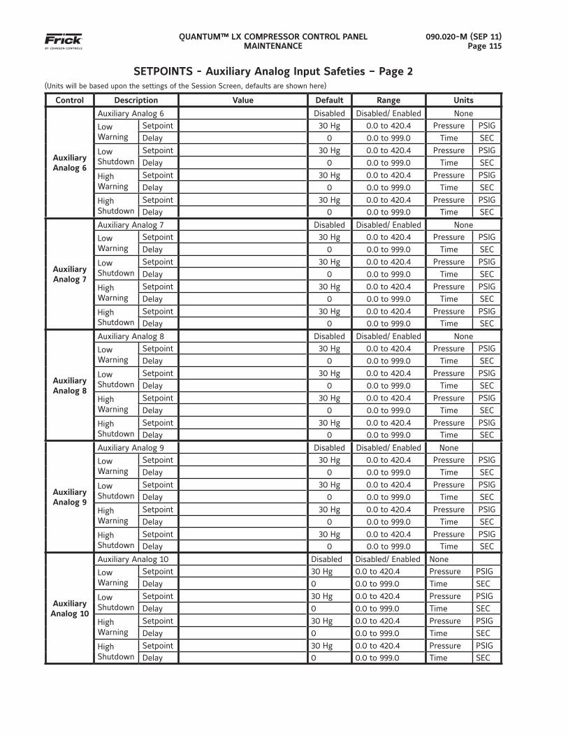
QUANTUM™ LX COMPRESSOR CONTROL PANELMAINTENANCE
090.020-M (SEP 11)Page 115
SETPOINTS - Auxiliary Analog Input Safeties – Page 2(Units will be based upon the settings of the Session Screen, defaults are shown here)
Control Description Value Default Range Units
Auxiliary Analog 6
Auxiliary Analog 6 Disabled Disabled/ Enabled None
Low Warning
Setpoint 30 Hg 0.0 to 420.4 Pressure PSIG
Delay 0 0.0 to 999.0 Time SEC
Low Shutdown
Setpoint 30 Hg 0.0 to 420.4 Pressure PSIG
Delay 0 0.0 to 999.0 Time SEC
High Warning
Setpoint 30 Hg 0.0 to 420.4 Pressure PSIG
Delay 0 0.0 to 999.0 Time SEC
High Shutdown
Setpoint 30 Hg 0.0 to 420.4 Pressure PSIG
Delay 0 0.0 to 999.0 Time SEC
Auxiliary Analog 7
Auxiliary Analog 7 Disabled Disabled/ Enabled None
Low Warning
Setpoint 30 Hg 0.0 to 420.4 Pressure PSIG
Delay 0 0.0 to 999.0 Time SEC
Low Shutdown
Setpoint 30 Hg 0.0 to 420.4 Pressure PSIG
Delay 0 0.0 to 999.0 Time SEC
High Warning
Setpoint 30 Hg 0.0 to 420.4 Pressure PSIG
Delay 0 0.0 to 999.0 Time SEC
High Shutdown
Setpoint 30 Hg 0.0 to 420.4 Pressure PSIG
Delay 0 0.0 to 999.0 Time SEC
Auxiliary Analog 8
Auxiliary Analog 8 Disabled Disabled/ Enabled None
Low Warning
Setpoint 30 Hg 0.0 to 420.4 Pressure PSIG
Delay 0 0.0 to 999.0 Time SEC
Low Shutdown
Setpoint 30 Hg 0.0 to 420.4 Pressure PSIG
Delay 0 0.0 to 999.0 Time SEC
High Warning
Setpoint 30 Hg 0.0 to 420.4 Pressure PSIG
Delay 0 0.0 to 999.0 Time SEC
High Shutdown
Setpoint 30 Hg 0.0 to 420.4 Pressure PSIG
Delay 0 0.0 to 999.0 Time SEC
Auxiliary Analog 9
Auxiliary Analog 9 Disabled Disabled/ Enabled None
Low Warning
Setpoint 30 Hg 0.0 to 420.4 Pressure PSIG
Delay 0 0.0 to 999.0 Time SEC
Low Shutdown
Setpoint 30 Hg 0.0 to 420.4 Pressure PSIG
Delay 0 0.0 to 999.0 Time SEC
High Warning
Setpoint 30 Hg 0.0 to 420.4 Pressure PSIG
Delay 0 0.0 to 999.0 Time SEC
High Shutdown
Setpoint 30 Hg 0.0 to 420.4 Pressure PSIG
Delay 0 0.0 to 999.0 Time SEC
Auxiliary Analog 10
Auxiliary Analog 10 Disabled Disabled/ Enabled None
Low Warning
Setpoint 30 Hg 0.0 to 420.4 Pressure PSIG
Delay 0 0.0 to 999.0 Time SEC
Low Shutdown
Setpoint 30 Hg 0.0 to 420.4 Pressure PSIG
Delay 0 0.0 to 999.0 Time SEC
High Warning
Setpoint 30 Hg 0.0 to 420.4 Pressure PSIG
Delay 0 0.0 to 999.0 Time SEC
High Shutdown
Setpoint 30 Hg 0.0 to 420.4 Pressure PSIG
Delay 0 0.0 to 999.0 Time SEC
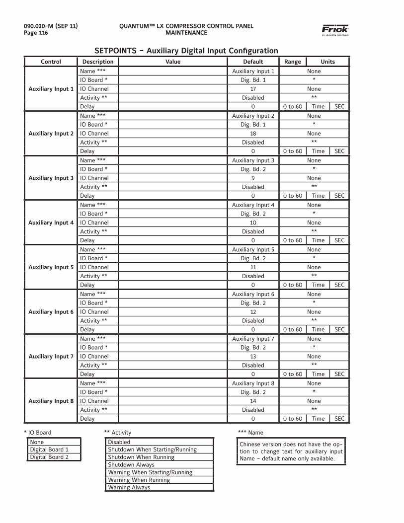
QUANTUM™ LX COMPRESSOR CONTROL PANELMAINTENANCE
090.020-M (SEP 11)Page 116
SETPOINTS – Auxiliary Digital Input Confi gurationControl Description Value Default Range Units
Auxiliary Input 1
Name *** Auxiliary Input 1 None
IO Board * Dig. Bd. 1 *
IO Channel 17 None
Activity ** Disabled **
Delay 0 0 to 60 Time SEC
Auxiliary Input 2
Name *** Auxiliary Input 2 None
IO Board * Dig. Bd. 1 *
IO Channel 18 None
Activity ** Disabled **
Delay 0 0 to 60 Time SEC
Auxiliary Input 3
Name *** Auxiliary Input 3 None
IO Board * Dig. Bd. 2 *
IO Channel 9 None
Activity ** Disabled **
Delay 0 0 to 60 Time SEC
Auxiliary Input 4
Name *** Auxiliary Input 4 None
IO Board * Dig. Bd. 2 *
IO Channel 10 None
Activity ** Disabled **
Delay 0 0 to 60 Time SEC
Auxiliary Input 5
Name *** Auxiliary Input 5 None
IO Board * Dig. Bd. 2 *
IO Channel 11 None
Activity ** Disabled **
Delay 0 0 to 60 Time SEC
Auxiliary Input 6
Name *** Auxiliary Input 6 None
IO Board * Dig. Bd. 2 *
IO Channel 12 None
Activity ** Disabled **
Delay 0 0 to 60 Time SEC
Auxiliary Input 7
Name *** Auxiliary Input 7 None
IO Board * Dig. Bd. 2 *
IO Channel 13 None
Activity ** Disabled **
Delay 0 0 to 60 Time SEC
Auxiliary Input 8
Name *** Auxiliary Input 8 None
IO Board * Dig. Bd. 2 *
IO Channel 14 None
Activity ** Disabled **
Delay 0 0 to 60 Time SEC
* IO Board ** Activity *** Name
None Disabled Chinese version does not have the op-tion to change text for auxiliary input Name – default name only available.
Digital Board 1 Shutdown When Starting/RunningDigital Board 2 Shutdown When Running
Shutdown AlwaysWarning When Starting/RunningWarning When RunningWarning Always
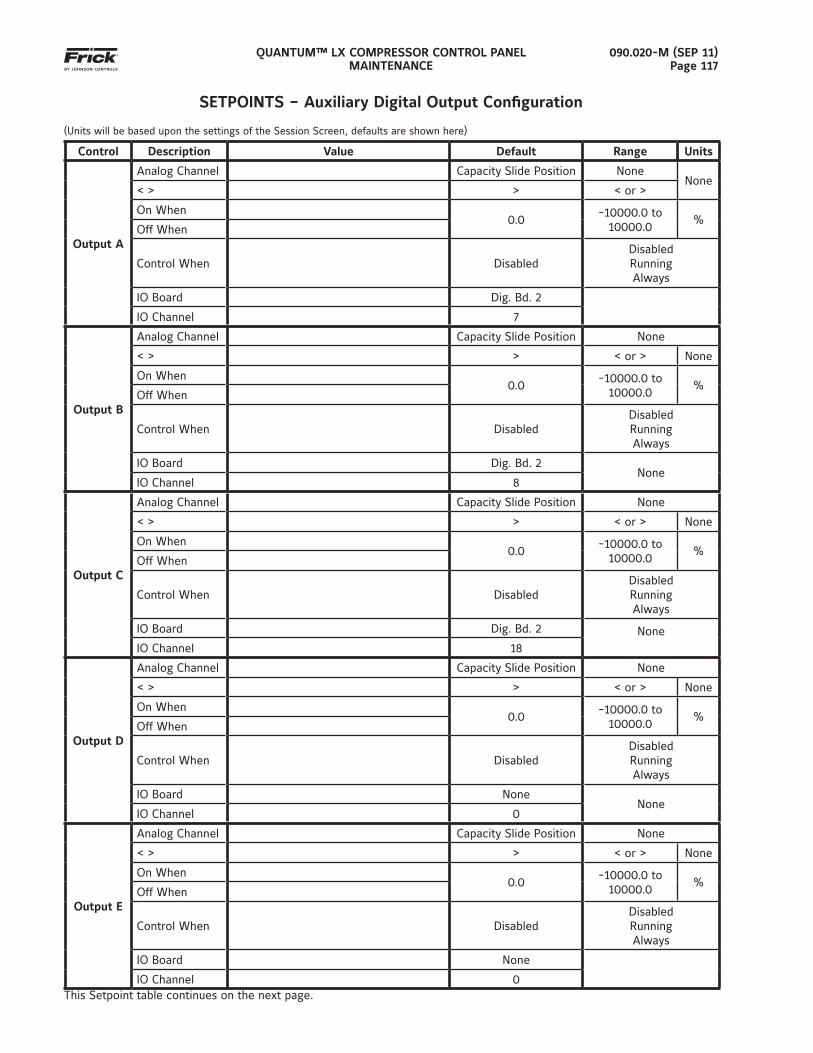
QUANTUM™ LX COMPRESSOR CONTROL PANELMAINTENANCE
090.020-M (SEP 11)Page 117
SETPOINTS – Auxiliary Digital Output Confi guration
(Units will be based upon the settings of the Session Screen, defaults are shown here)
Control Description Value Default Range Units
Output A
Analog Channel Capacity Slide Position NoneNone
< > > < or >
On When0.0
-10000.0 to 10000.0
%Off When
Control When DisabledDisabledRunningAlways
IO Board Dig. Bd. 2
IO Channel 7
Output B
Analog Channel Capacity Slide Position None
< > > < or > None
On When0.0
-10000.0 to 10000.0
%Off When
Control When DisabledDisabledRunningAlways
IO Board Dig. Bd. 2None
IO Channel 8
Output C
Analog Channel Capacity Slide Position None
< > > < or > None
On When0.0
-10000.0 to 10000.0
%Off When
Control When DisabledDisabledRunningAlways
IO Board Dig. Bd. 2 NoneIO Channel 18
Output D
Analog Channel Capacity Slide Position None
< > > < or > None
On When0.0
-10000.0 to 10000.0
%Off When
Control When DisabledDisabledRunningAlways
IO Board NoneNone
IO Channel 0
Output E
Analog Channel Capacity Slide Position None
< > > < or > None
On When0.0
-10000.0 to 10000.0
%Off When
Control When DisabledDisabledRunningAlways
IO Board None
IO Channel 0This Setpoint table continues on the next page.
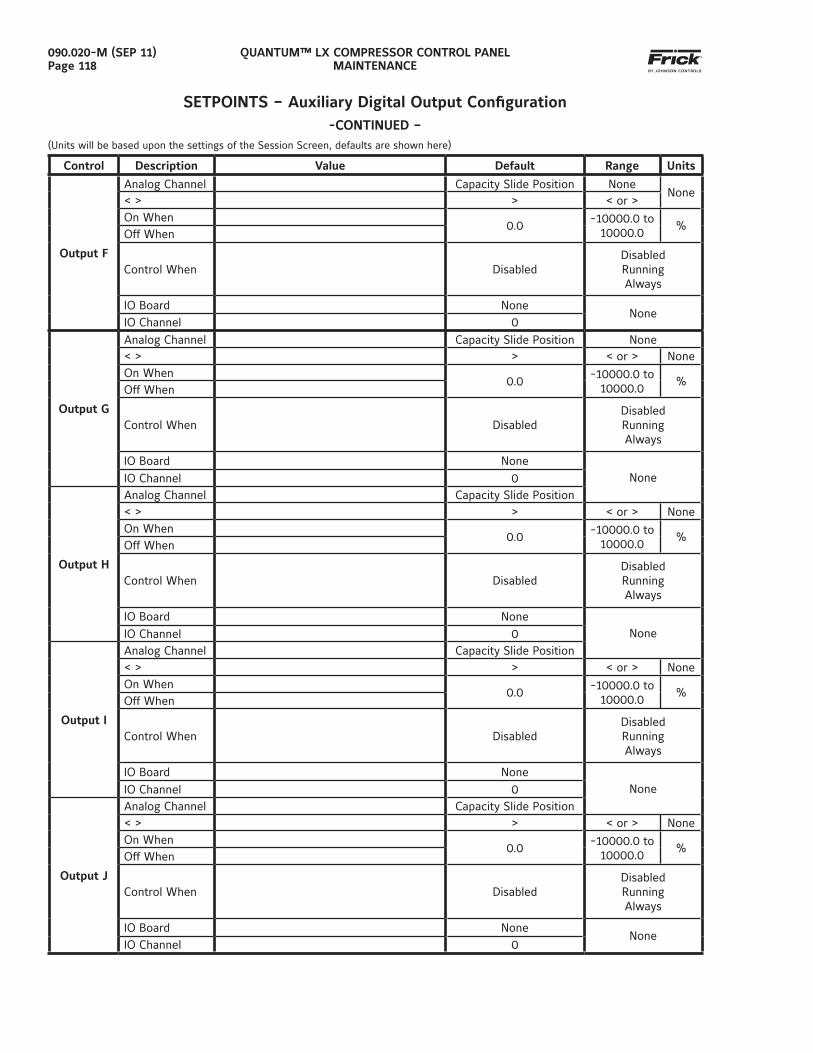
QUANTUM™ LX COMPRESSOR CONTROL PANELMAINTENANCE
090.020-M (SEP 11)Page 118
SETPOINTS – Auxiliary Digital Output Confi guration-CONTINUED –
(Units will be based upon the settings of the Session Screen, defaults are shown here)
Control Description Value Default Range Units
Output F
Analog Channel Capacity Slide Position NoneNone
< > > < or >On When
0.0-10000.0 to
10000.0%
Off When
Control When DisabledDisabledRunningAlways
IO Board NoneNone
IO Channel 0
Output G
Analog Channel Capacity Slide Position None< > > < or > NoneOn When
0.0-10000.0 to
10000.0%
Off When
Control When DisabledDisabledRunningAlways
IO Board NoneNoneIO Channel 0
Output H
Analog Channel Capacity Slide Position< > > < or > NoneOn When
0.0-10000.0 to
10000.0%
Off When
Control When DisabledDisabledRunningAlways
IO Board NoneNoneIO Channel 0
Output I
Analog Channel Capacity Slide Position< > > < or > NoneOn When
0.0-10000.0 to
10000.0%
Off When
Control When DisabledDisabledRunningAlways
IO Board NoneNoneIO Channel 0
Output J
Analog Channel Capacity Slide Position< > > < or > NoneOn When
0.0-10000.0 to
10000.0%
Off When
Control When DisabledDisabledRunningAlways
IO Board NoneNone
IO Channel 0
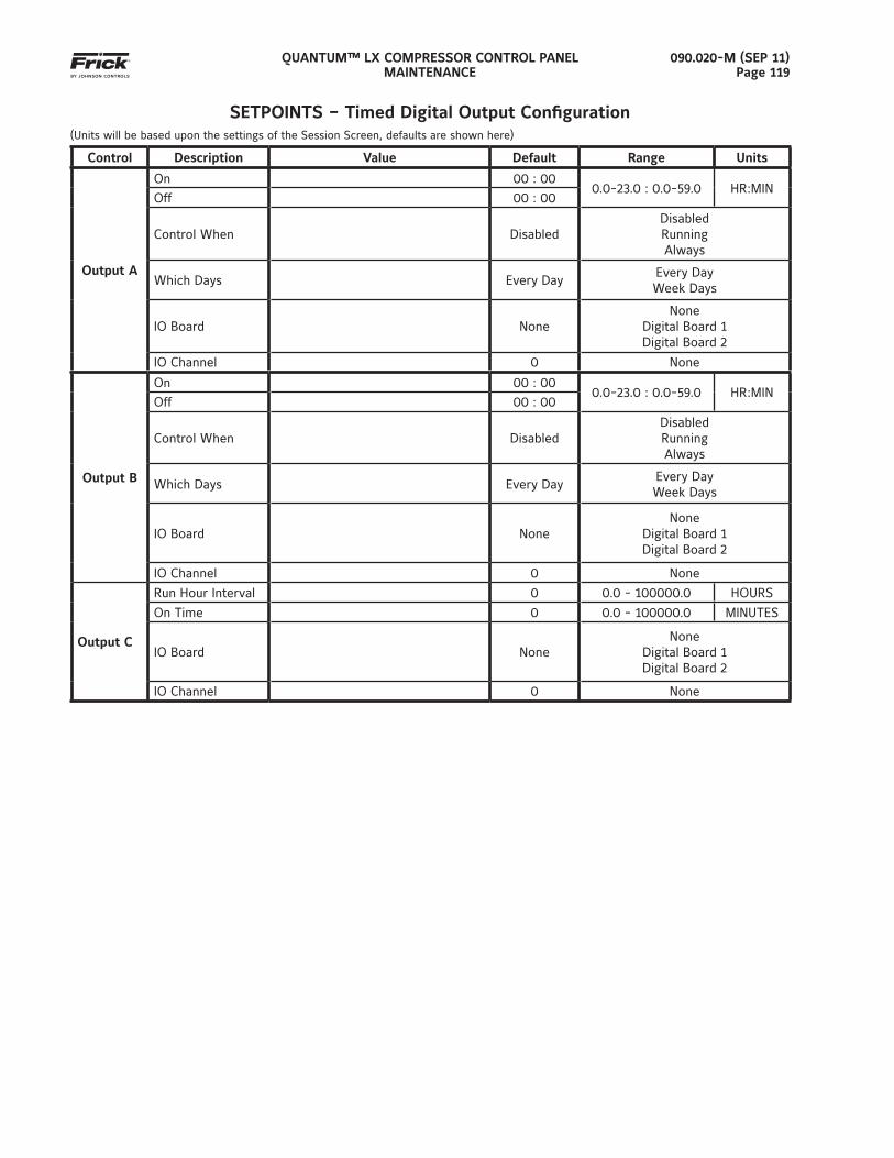
QUANTUM™ LX COMPRESSOR CONTROL PANELMAINTENANCE
090.020-M (SEP 11)Page 119
SETPOINTS – Timed Digital Output Confi guration(Units will be based upon the settings of the Session Screen, defaults are shown here)
Control Description Value Default Range Units
Output A
On 00 : 000.0-23.0 : 0.0-59.0 HR:MIN
Off 00 : 00
Control When DisabledDisabledRunningAlways
Which Days Every DayEvery DayWeek Days
IO Board NoneNone
Digital Board 1Digital Board 2
IO Channel 0 None
Output B
On 00 : 000.0-23.0 : 0.0-59.0 HR:MIN
Off 00 : 00
Control When DisabledDisabledRunningAlways
Which Days Every DayEvery DayWeek Days
IO Board NoneNone
Digital Board 1Digital Board 2
IO Channel 0 None
Output C
Run Hour Interval 0 0.0 - 100000.0 HOURS
On Time 0 0.0 - 100000.0 MINUTES
IO Board NoneNone
Digital Board 1Digital Board 2
IO Channel 0 None
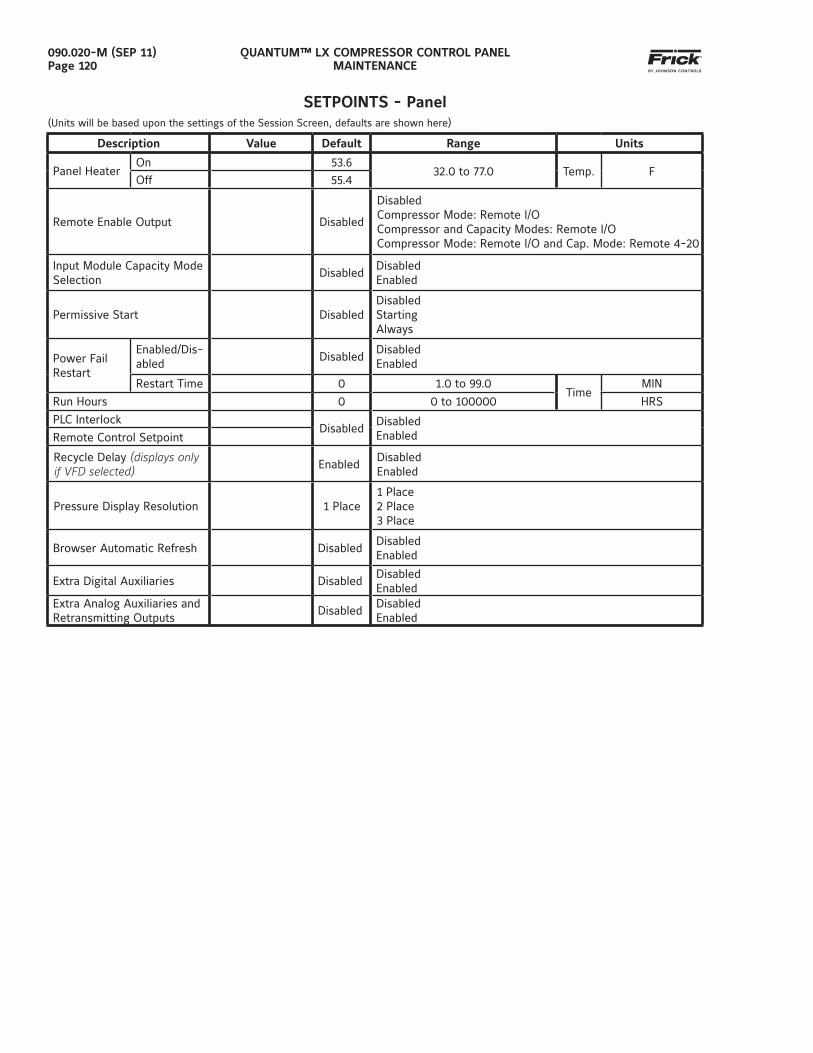
QUANTUM™ LX COMPRESSOR CONTROL PANELMAINTENANCE
090.020-M (SEP 11)Page 120
SETPOINTS - Panel(Units will be based upon the settings of the Session Screen, defaults are shown here)
Description Value Default Range Units
Panel Heater On 53.6
32.0 to 77.0 Temp. FOff 55.4
Remote Enable Output Disabled
DisabledCompressor Mode: Remote I/OCompressor and Capacity Modes: Remote I/OCompressor Mode: Remote I/O and Cap. Mode: Remote 4-20
Input Module Capacity Mode Selection
DisabledDisabledEnabled
Permissive Start DisabledDisabledStartingAlways
Power Fail Restart
Enabled/Dis-abled
DisabledDisabledEnabled
Restart Time 0 1.0 to 99.0Time
MIN
Run Hours 0 0 to 100000 HRS
PLC InterlockDisabled
DisabledEnabledRemote Control Setpoint
Recycle Delay (displays only if VFD selected) Enabled
DisabledEnabled
Pressure Display Resolution 1 Place1 Place2 Place3 Place
Browser Automatic Refresh DisabledDisabledEnabled
Extra Digital Auxiliaries DisabledDisabledEnabled
Extra Analog Auxiliaries and Retransmitting Outputs
DisabledDisabledEnabled
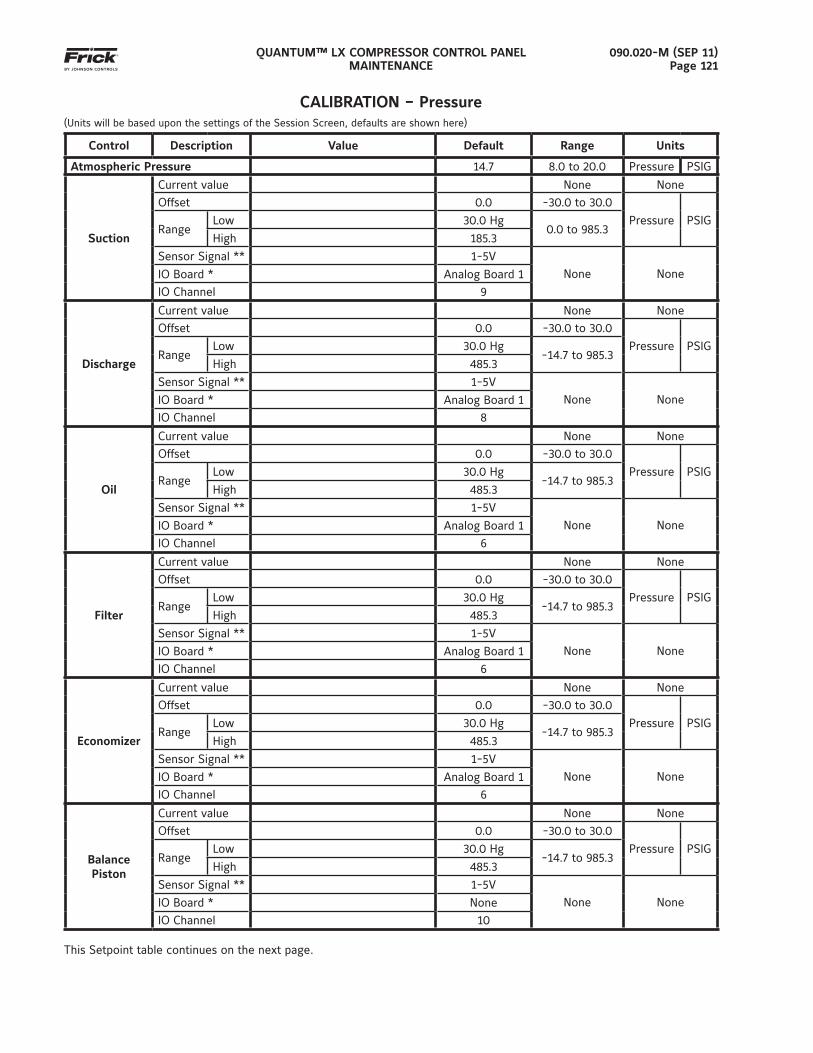
QUANTUM™ LX COMPRESSOR CONTROL PANELMAINTENANCE
090.020-M (SEP 11)Page 121
CALIBRATION – Pressure(Units will be based upon the settings of the Session Screen, defaults are shown here)
Control Description Value Default Range Units
Atmospheric Pressure 14.7 8.0 to 20.0 Pressure PSIG
Suction
Current value None None
Offset 0.0 -30.0 to 30.0
Pressure PSIGRange
Low 30.0 Hg0.0 to 985.3
High 185.3
Sensor Signal ** 1-5V
None NoneIO Board * Analog Board 1
IO Channel 9
Discharge
Current value None None
Offset 0.0 -30.0 to 30.0
Pressure PSIGRange
Low 30.0 Hg-14.7 to 985.3
High 485.3
Sensor Signal ** 1-5V
None NoneIO Board * Analog Board 1
IO Channel 8
Oil
Current value None None
Offset 0.0 -30.0 to 30.0
Pressure PSIGRange
Low 30.0 Hg-14.7 to 985.3
High 485.3
Sensor Signal ** 1-5V
None NoneIO Board * Analog Board 1
IO Channel 6
Filter
Current value None None
Offset 0.0 -30.0 to 30.0
Pressure PSIGRange
Low 30.0 Hg-14.7 to 985.3
High 485.3
Sensor Signal ** 1-5V
None NoneIO Board * Analog Board 1
IO Channel 6
Economizer
Current value None None
Offset 0.0 -30.0 to 30.0
Pressure PSIGRange
Low 30.0 Hg-14.7 to 985.3
High 485.3
Sensor Signal ** 1-5V
None NoneIO Board * Analog Board 1
IO Channel 6
Balance Piston
Current value None None
Offset 0.0 -30.0 to 30.0
Pressure PSIGRange
Low 30.0 Hg-14.7 to 985.3
High 485.3
Sensor Signal ** 1-5V
None NoneIO Board * None
IO Channel 10
This Setpoint table continues on the next page.
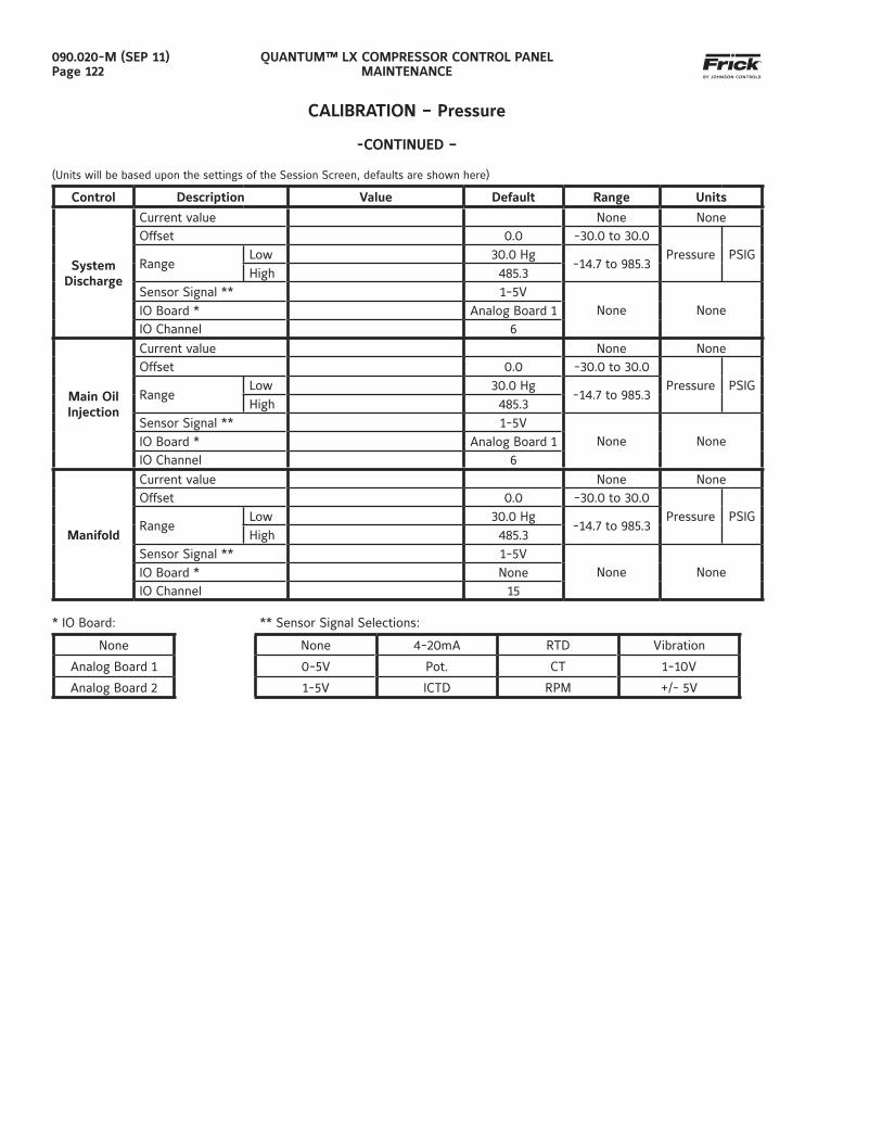
QUANTUM™ LX COMPRESSOR CONTROL PANELMAINTENANCE
090.020-M (SEP 11)Page 122
CALIBRATION – Pressure
-CONTINUED –
(Units will be based upon the settings of the Session Screen, defaults are shown here)
Control Description Value Default Range Units
System Discharge
Current value None NoneOffset 0.0 -30.0 to 30.0
Pressure PSIGRange
Low 30.0 Hg-14.7 to 985.3
High 485.3Sensor Signal ** 1-5V
None NoneIO Board * Analog Board 1IO Channel 6
Main Oil Injection
Current value None NoneOffset 0.0 -30.0 to 30.0
Pressure PSIGRange
Low 30.0 Hg-14.7 to 985.3
High 485.3Sensor Signal ** 1-5V
None NoneIO Board * Analog Board 1IO Channel 6
Manifold
Current value None NoneOffset 0.0 -30.0 to 30.0
Pressure PSIGRange
Low 30.0 Hg-14.7 to 985.3
High 485.3Sensor Signal ** 1-5V
None NoneIO Board * NoneIO Channel 15
* IO Board: ** Sensor Signal Selections:
None None 4-20mA RTD Vibration
Analog Board 1 0-5V Pot. CT 1-10V
Analog Board 2 1-5V ICTD RPM +/- 5V
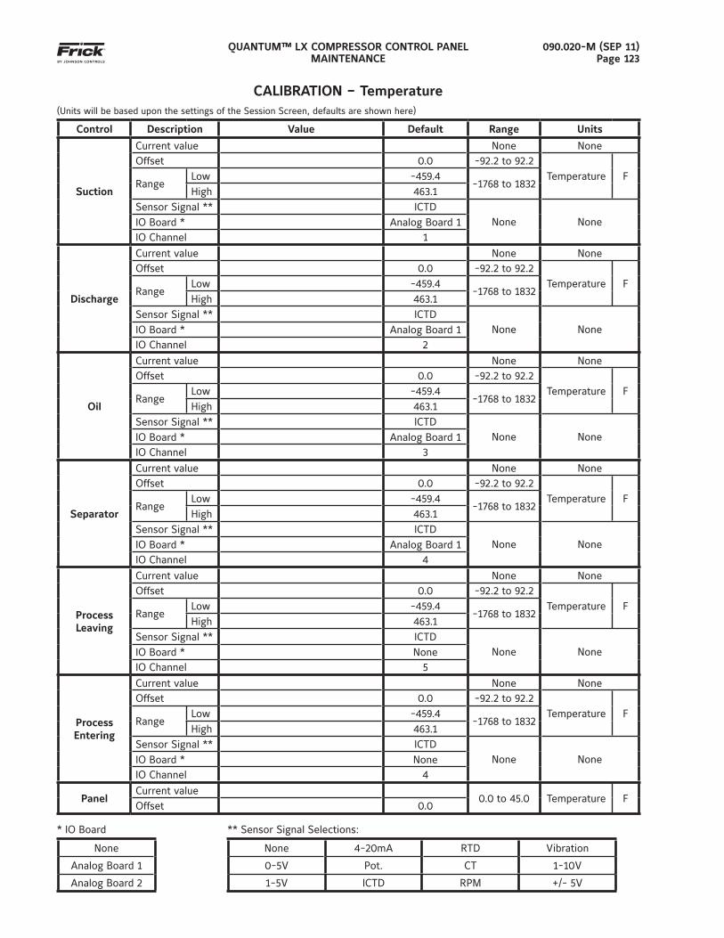
QUANTUM™ LX COMPRESSOR CONTROL PANELMAINTENANCE
090.020-M (SEP 11)Page 123
CALIBRATION – Temperature(Units will be based upon the settings of the Session Screen, defaults are shown here)
Control Description Value Default Range Units
Suction
Current value None NoneOffset 0.0 -92.2 to 92.2
Temperature FRange
Low -459.4-1768 to 1832
High 463.1Sensor Signal ** ICTD
None NoneIO Board * Analog Board 1IO Channel 1
Discharge
Current value None NoneOffset 0.0 -92.2 to 92.2
Temperature FRange
Low -459.4-1768 to 1832
High 463.1Sensor Signal ** ICTD
None NoneIO Board * Analog Board 1IO Channel 2
Oil
Current value None NoneOffset 0.0 -92.2 to 92.2
Temperature FRange
Low -459.4-1768 to 1832
High 463.1Sensor Signal ** ICTD
None NoneIO Board * Analog Board 1IO Channel 3
Separator
Current value None NoneOffset 0.0 -92.2 to 92.2
Temperature FRange
Low -459.4-1768 to 1832
High 463.1Sensor Signal ** ICTD
None NoneIO Board * Analog Board 1IO Channel 4
Process Leaving
Current value None NoneOffset 0.0 -92.2 to 92.2
Temperature FRange
Low -459.4-1768 to 1832
High 463.1Sensor Signal ** ICTD
None NoneIO Board * NoneIO Channel 5
Process Entering
Current value None NoneOffset 0.0 -92.2 to 92.2
Temperature FRange
Low -459.4-1768 to 1832
High 463.1Sensor Signal ** ICTD
None NoneIO Board * NoneIO Channel 4
PanelCurrent value
0.0 to 45.0 Temperature FOffset 0.0
* IO Board ** Sensor Signal Selections:
None None 4-20mA RTD Vibration
Analog Board 1 0-5V Pot. CT 1-10V
Analog Board 2 1-5V ICTD RPM +/- 5V
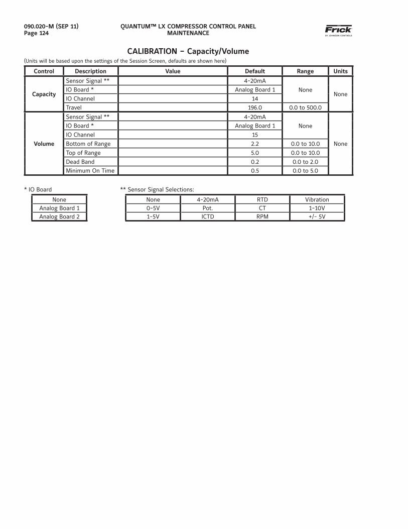
QUANTUM™ LX COMPRESSOR CONTROL PANELMAINTENANCE
090.020-M (SEP 11)Page 124
CALIBRATION – Capacity/Volume(Units will be based upon the settings of the Session Screen, defaults are shown here)
Control Description Value Default Range Units
Capacity
Sensor Signal ** 4-20mA
NoneNone
IO Board * Analog Board 1
IO Channel 14
Travel 196.0 0.0 to 500.0
Volume
Sensor Signal ** 4-20mA
None
None
IO Board * Analog Board 1
IO Channel 15
Bottom of Range 2.2 0.0 to 10.0
Top of Range 5.0 0.0 to 10.0
Dead Band 0.2 0.0 to 2.0
Minimum On Time 0.5 0.0 to 5.0
* IO Board ** Sensor Signal Selections:
None None 4-20mA RTD VibrationAnalog Board 1 0-5V Pot. CT 1-10VAnalog Board 2 1-5V ICTD RPM +/- 5V
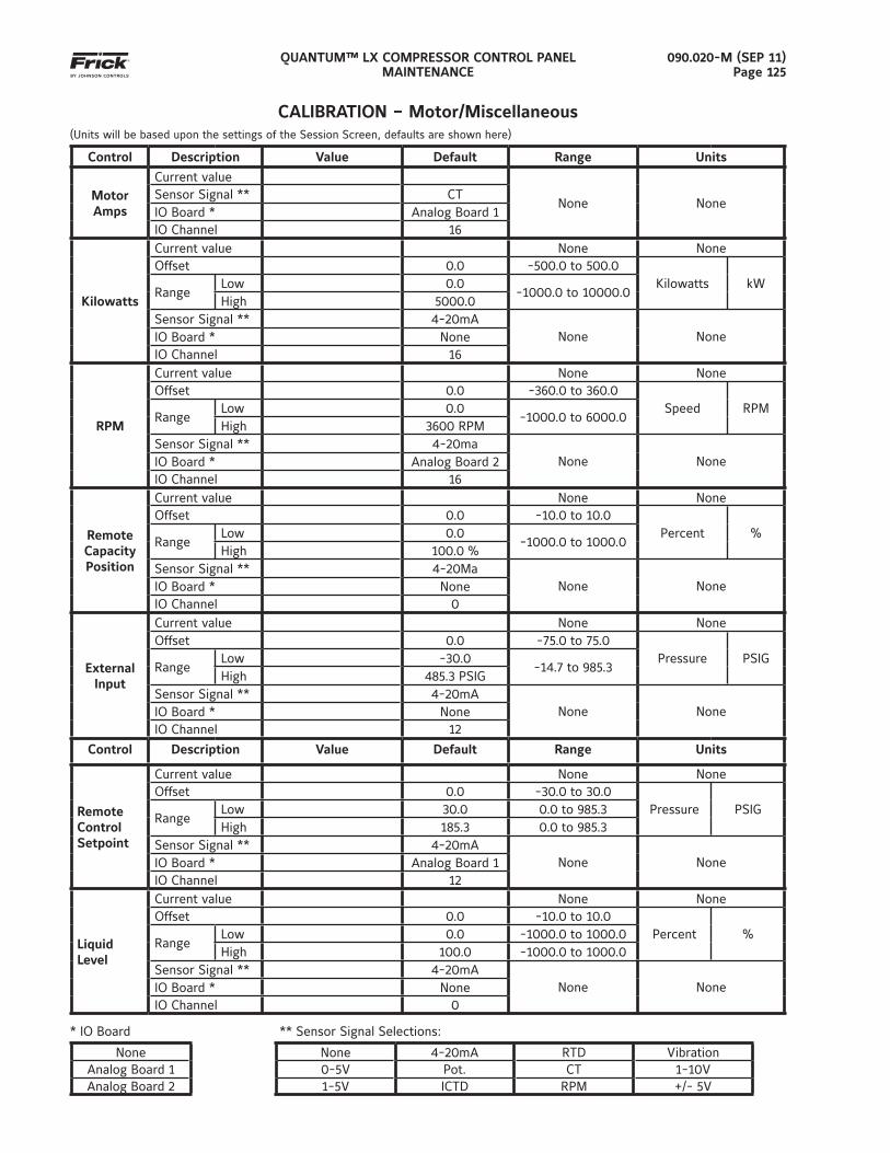
QUANTUM™ LX COMPRESSOR CONTROL PANELMAINTENANCE
090.020-M (SEP 11)Page 125
CALIBRATION – Motor/Miscellaneous(Units will be based upon the settings of the Session Screen, defaults are shown here)
Control Description Value Default Range Units
MotorAmps
Current value
None NoneSensor Signal ** CTIO Board * Analog Board 1IO Channel 16
Kilowatts
Current value None NoneOffset 0.0 -500.0 to 500.0
Kilowatts kWRange
Low 0.0-1000.0 to 10000.0
High 5000.0Sensor Signal ** 4-20mA
None NoneIO Board * NoneIO Channel 16
RPM
Current value None NoneOffset 0.0 -360.0 to 360.0
Speed RPMRange
Low 0.0-1000.0 to 6000.0
High 3600 RPMSensor Signal ** 4-20ma
None NoneIO Board * Analog Board 2IO Channel 16
Remote Capacity Position
Current value None NoneOffset 0.0 -10.0 to 10.0
Percent %Range
Low 0.0-1000.0 to 1000.0
High 100.0 %Sensor Signal ** 4-20Ma
None NoneIO Board * NoneIO Channel 0
External Input
Current value None NoneOffset 0.0 -75.0 to 75.0
Pressure PSIGRange
Low -30.0-14.7 to 985.3
High 485.3 PSIGSensor Signal ** 4-20mA
None NoneIO Board * NoneIO Channel 12
Control Description Value Default Range Units
Remote Control Setpoint
Current value None NoneOffset 0.0 -30.0 to 30.0
Pressure PSIGRange
Low 30.0 0.0 to 985.3High 185.3 0.0 to 985.3
Sensor Signal ** 4-20mANone NoneIO Board * Analog Board 1
IO Channel 12
Liquid Level
Current value None NoneOffset 0.0 -10.0 to 10.0
Percent %Range
Low 0.0 -1000.0 to 1000.0High 100.0 -1000.0 to 1000.0
Sensor Signal ** 4-20mANone NoneIO Board * None
IO Channel 0
* IO Board ** Sensor Signal Selections:
None None 4-20mA RTD VibrationAnalog Board 1 0-5V Pot. CT 1-10VAnalog Board 2 1-5V ICTD RPM +/- 5V
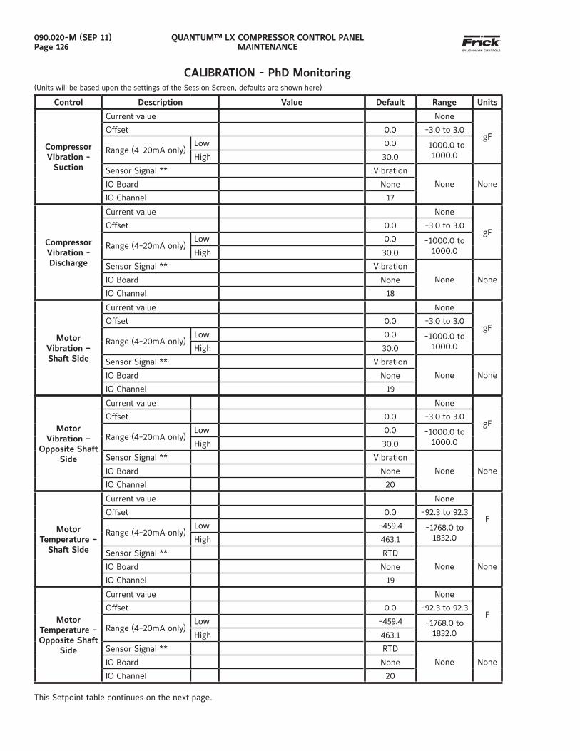
QUANTUM™ LX COMPRESSOR CONTROL PANELMAINTENANCE
090.020-M (SEP 11)Page 126
CALIBRATION - PhD Monitoring(Units will be based upon the settings of the Session Screen, defaults are shown here)
Control Description Value Default Range Units
Compressor Vibration -
Suction
Current value None
gFOffset 0.0 -3.0 to 3.0
Range (4-20mA only)Low 0.0 -1000.0 to
1000.0High 30.0
Sensor Signal ** Vibration
None NoneIO Board None
IO Channel 17
Compressor Vibration -Discharge
Current value None
gFOffset 0.0 -3.0 to 3.0
Range (4-20mA only)Low 0.0 -1000.0 to
1000.0High 30.0
Sensor Signal ** Vibration
None NoneIO Board None
IO Channel 18
MotorVibration – Shaft Side
Current value None
gFOffset 0.0 -3.0 to 3.0
Range (4-20mA only)Low 0.0 -1000.0 to
1000.0High 30.0
Sensor Signal ** Vibration
None NoneIO Board None
IO Channel 19
MotorVibration –
Opposite Shaft Side
Current value None
gFOffset 0.0 -3.0 to 3.0
Range (4-20mA only)Low 0.0 -1000.0 to
1000.0High 30.0
Sensor Signal ** Vibration
None NoneIO Board None
IO Channel 20
MotorTemperature –
Shaft Side
Current value None
FOffset 0.0 -92.3 to 92.3
Range (4-20mA only)Low -459.4 -1768.0 to
1832.0High 463.1
Sensor Signal ** RTD
None NoneIO Board None
IO Channel 19
MotorTemperature – Opposite Shaft
Side
Current value None
FOffset 0.0 -92.3 to 92.3
Range (4-20mA only)Low -459.4 -1768.0 to
1832.0High 463.1
Sensor Signal ** RTD
None NoneIO Board None
IO Channel 20
This Setpoint table continues on the next page.
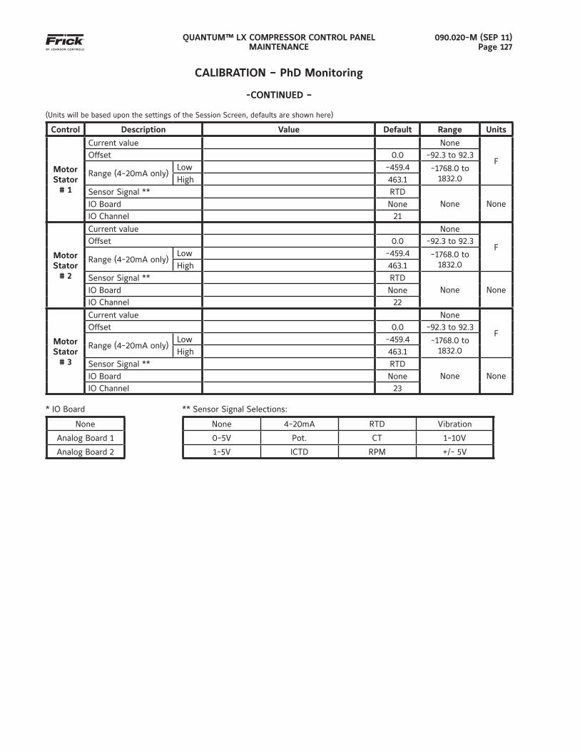
QUANTUM™ LX COMPRESSOR CONTROL PANELMAINTENANCE
090.020-M (SEP 11)Page 127
CALIBRATION – PhD Monitoring
-CONTINUED –
(Units will be based upon the settings of the Session Screen, defaults are shown here)
Control Description Value Default Range Units
Motor Stator
# 1
Current value None
FOffset 0.0 -92.3 to 92.3
Range (4-20mA only)Low -459.4 -1768.0 to
1832.0High 463.1Sensor Signal ** RTD
None NoneIO Board NoneIO Channel 21
Motor Stator
# 2
Current value None
FOffset 0.0 -92.3 to 92.3
Range (4-20mA only)Low -459.4 -1768.0 to
1832.0High 463.1Sensor Signal ** RTD
None NoneIO Board NoneIO Channel 22
Motor Stator
# 3
Current value None
FOffset 0.0 -92.3 to 92.3
Range (4-20mA only)Low -459.4 -1768.0 to
1832.0High 463.1Sensor Signal ** RTD
None NoneIO Board NoneIO Channel 23
* IO Board ** Sensor Signal Selections:
None None 4-20mA RTD Vibration
Analog Board 1 0-5V Pot. CT 1-10V
Analog Board 2 1-5V ICTD RPM +/- 5V
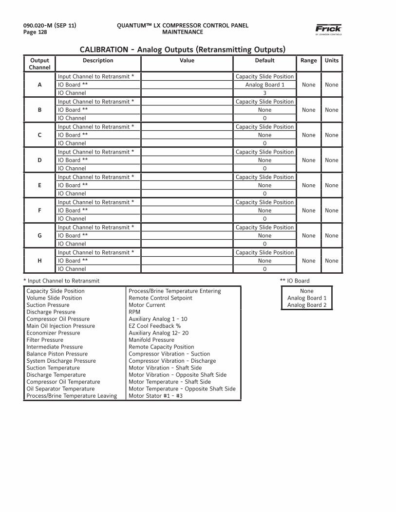
QUANTUM™ LX COMPRESSOR CONTROL PANELMAINTENANCE
090.020-M (SEP 11)Page 128
CALIBRATION - Analog Outputs (Retransmitting Outputs)Output Channel
Description Value Default Range Units
AInput Channel to Retransmit * Capacity Slide Position
None NoneIO Board ** Analog Board 1IO Channel 3
BInput Channel to Retransmit * Capacity Slide Position
None NoneIO Board ** NoneIO Channel 0
CInput Channel to Retransmit * Capacity Slide Position
None NoneIO Board ** NoneIO Channel 0
DInput Channel to Retransmit * Capacity Slide Position
None NoneIO Board ** NoneIO Channel 0
EInput Channel to Retransmit * Capacity Slide Position
None NoneIO Board ** NoneIO Channel 0
FInput Channel to Retransmit * Capacity Slide Position
None NoneIO Board ** NoneIO Channel 0
GInput Channel to Retransmit * Capacity Slide Position
None NoneIO Board ** NoneIO Channel 0
HInput Channel to Retransmit * Capacity Slide Position
None NoneIO Board ** NoneIO Channel 0
* Input Channel to Retransmit ** IO Board
Capacity Slide PositionVolume Slide PositionSuction PressureDischarge PressureCompressor Oil PressureMain Oil Injection PressureEconomizer PressureFilter PressureIntermediate PressureBalance Piston PressureSystem Discharge PressureSuction TemperatureDischarge TemperatureCompressor Oil TemperatureOil Separator TemperatureProcess/Brine Temperature Leaving
Process/Brine Temperature EnteringRemote Control SetpointMotor CurrentRPMAuxiliary Analog 1 - 10EZ Cool Feedback %Auxiliary Analog 12- 20Manifold PressureRemote Capacity PositionCompressor Vibration - SuctionCompressor Vibration - DischargeMotor Vibration - Shaft SideMotor Vibration - Opposite Shaft SideMotor Temperature - Shaft SideMotor Temperature - Opposite Shaft SideMotor Stator #1 - #3
NoneAnalog Board 1Analog Board 2
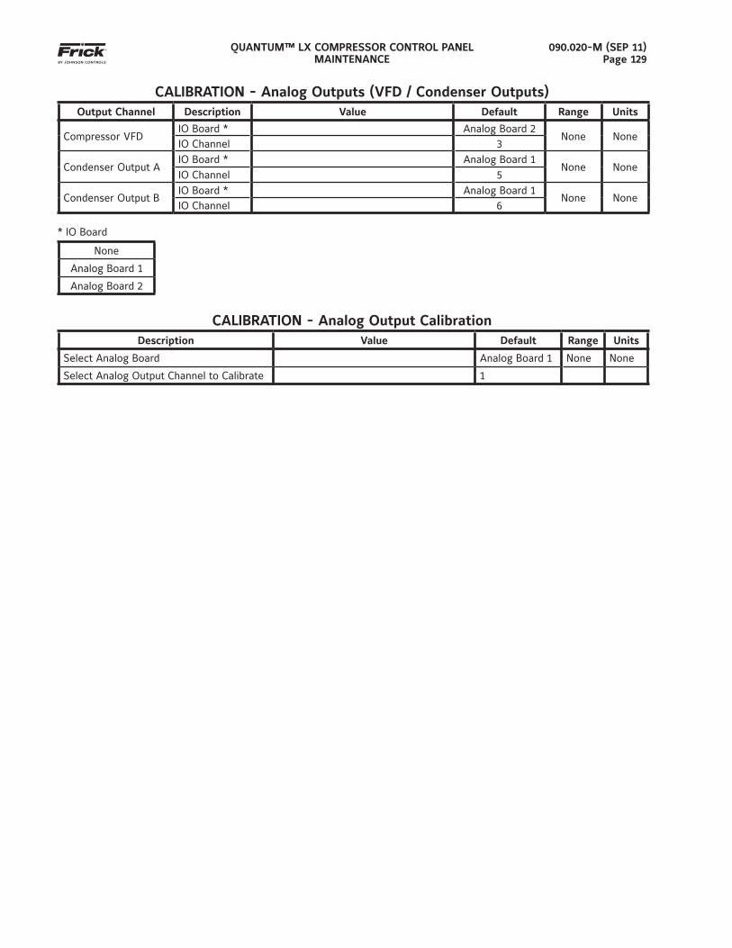
QUANTUM™ LX COMPRESSOR CONTROL PANELMAINTENANCE
090.020-M (SEP 11)Page 129
CALIBRATION - Analog Outputs (VFD / Condenser Outputs)Output Channel Description Value Default Range Units
Compressor VFDIO Board * Analog Board 2
None NoneIO Channel 3
Condenser Output AIO Board * Analog Board 1
None NoneIO Channel 5
Condenser Output BIO Board * Analog Board 1
None NoneIO Channel 6
* IO Board
None
Analog Board 1
Analog Board 2
CALIBRATION - Analog Output CalibrationDescription Value Default Range Units
Select Analog Board Analog Board 1 None None
Select Analog Output Channel to Calibrate 1
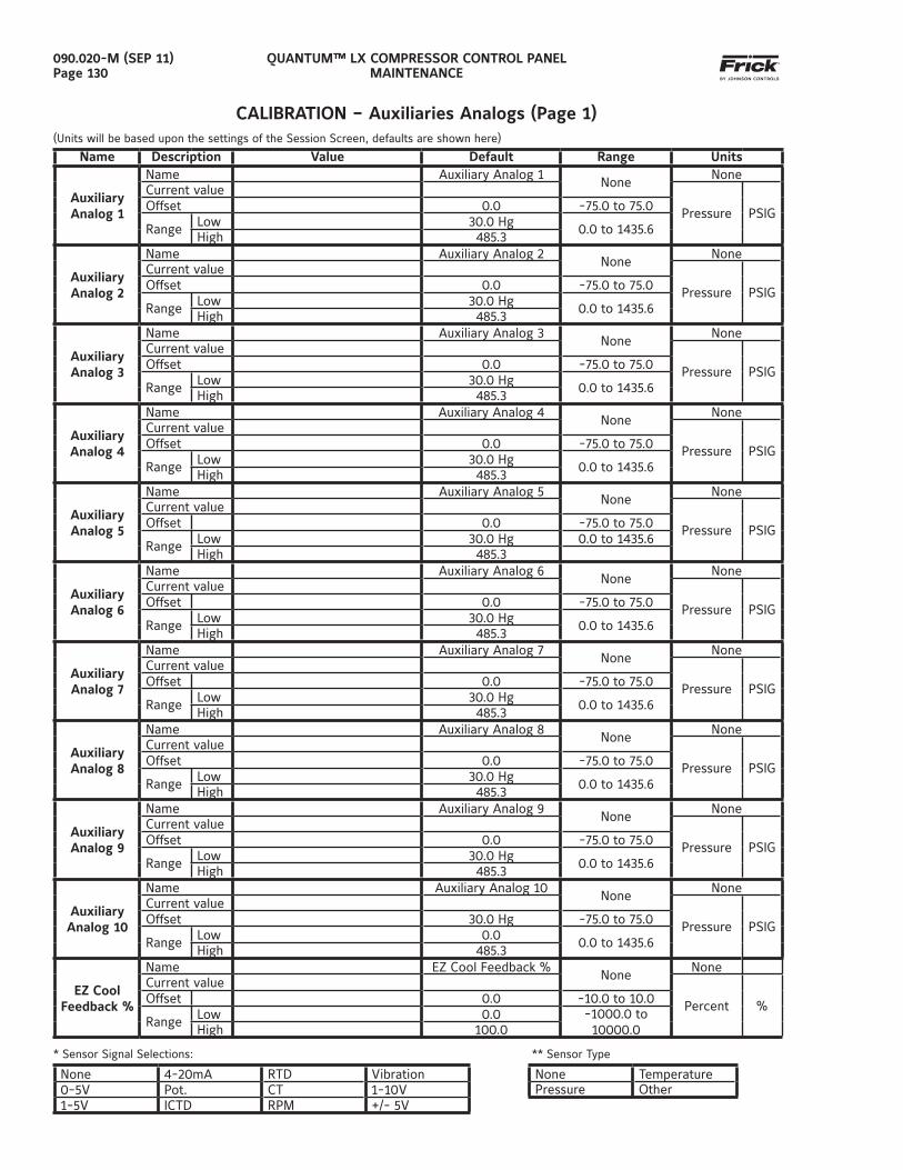
QUANTUM™ LX COMPRESSOR CONTROL PANELMAINTENANCE
090.020-M (SEP 11)Page 130
CALIBRATION – Auxiliaries Analogs (Page 1)(Units will be based upon the settings of the Session Screen, defaults are shown here)
Name Description Value Default Range Units
Auxiliary Analog 1
Name Auxiliary Analog 1None
NoneCurrent value
Pressure PSIGOffset 0.0 -75.0 to 75.0
Range Low 30.0 Hg 0.0 to 1435.6High 485.3
Auxiliary Analog 2
Name Auxiliary Analog 2None
NoneCurrent value
Pressure PSIGOffset 0.0 -75.0 to 75.0
Range Low 30.0 Hg 0.0 to 1435.6High 485.3
Auxiliary Analog 3
Name Auxiliary Analog 3None
NoneCurrent value
Pressure PSIGOffset 0.0 -75.0 to 75.0
Range Low 30.0 Hg 0.0 to 1435.6High 485.3
Auxiliary Analog 4
Name Auxiliary Analog 4None
NoneCurrent value
Pressure PSIGOffset 0.0 -75.0 to 75.0
Range Low 30.0 Hg 0.0 to 1435.6High 485.3
Auxiliary Analog 5
Name Auxiliary Analog 5None
NoneCurrent value
Pressure PSIGOffset 0.0 -75.0 to 75.0
Range Low 30.0 Hg 0.0 to 1435.6High 485.3
Auxiliary Analog 6
Name Auxiliary Analog 6None
NoneCurrent value
Pressure PSIGOffset 0.0 -75.0 to 75.0
Range Low 30.0 Hg 0.0 to 1435.6High 485.3
Auxiliary Analog 7
Name Auxiliary Analog 7None
NoneCurrent value
Pressure PSIGOffset 0.0 -75.0 to 75.0
Range Low 30.0 Hg 0.0 to 1435.6High 485.3
Auxiliary Analog 8
Name Auxiliary Analog 8None
NoneCurrent value
Pressure PSIGOffset 0.0 -75.0 to 75.0
Range Low 30.0 Hg 0.0 to 1435.6High 485.3
Auxiliary Analog 9
Name Auxiliary Analog 9None
NoneCurrent value
Pressure PSIGOffset 0.0 -75.0 to 75.0
Range Low 30.0 Hg 0.0 to 1435.6High 485.3
Auxiliary Analog 10
Name Auxiliary Analog 10None
NoneCurrent value
Pressure PSIGOffset 30.0 Hg -75.0 to 75.0
Range Low 0.0 0.0 to 1435.6High 485.3
EZ Cool Feedback %
Name EZ Cool Feedback %None
NoneCurrent value
Percent %Offset 0.0 -10.0 to 10.0
Range Low 0.0 -1000.0 to 10000.0High 100.0
* Sensor Signal Selections: ** Sensor Type
None 4-20mA RTD Vibration None Temperature0-5V Pot. CT 1-10V Pressure Other1-5V ICTD RPM +/- 5V
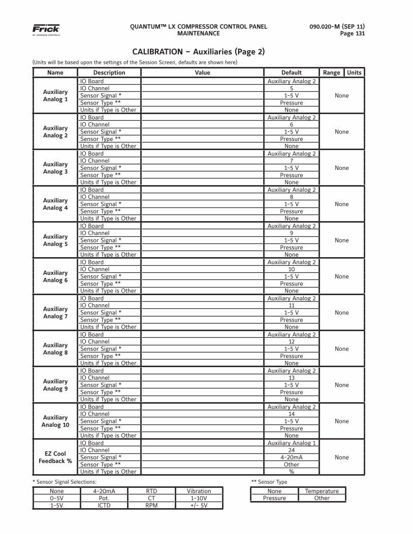
QUANTUM™ LX COMPRESSOR CONTROL PANELMAINTENANCE
090.020-M (SEP 11)Page 131
CALIBRATION – Auxiliaries (Page 2)(Units will be based upon the settings of the Session Screen, defaults are shown here)
Name Description Value Default Range Units
AuxiliaryAnalog 1
IO Board Auxiliary Analog 2
NoneIO Channel 5Sensor Signal * 1-5 VSensor Type ** PressureUnits if Type is Other None
AuxiliaryAnalog 2
IO Board Auxiliary Analog 2
NoneIO Channel 6Sensor Signal * 1-5 VSensor Type ** PressureUnits if Type is Other None
AuxiliaryAnalog 3
IO Board Auxiliary Analog 2
NoneIO Channel 7Sensor Signal * 1-5 VSensor Type ** PressureUnits if Type is Other None
AuxiliaryAnalog 4
IO Board Auxiliary Analog 2
NoneIO Channel 8Sensor Signal * 1-5 VSensor Type ** PressureUnits if Type is Other None
AuxiliaryAnalog 5
IO Board Auxiliary Analog 2
NoneIO Channel 9Sensor Signal * 1-5 VSensor Type ** PressureUnits if Type is Other None
AuxiliaryAnalog 6
IO Board Auxiliary Analog 2
NoneIO Channel 10Sensor Signal * 1-5 VSensor Type ** PressureUnits if Type is Other None
AuxiliaryAnalog 7
IO Board Auxiliary Analog 2
NoneIO Channel 11Sensor Signal * 1-5 VSensor Type ** PressureUnits if Type is Other None
AuxiliaryAnalog 8
IO Board Auxiliary Analog 2
NoneIO Channel 12Sensor Signal * 1-5 VSensor Type ** PressureUnits if Type is Other None
AuxiliaryAnalog 9
IO Board Auxiliary Analog 2
NoneIO Channel 13Sensor Signal * 1-5 VSensor Type ** PressureUnits if Type is Other None
AuxiliaryAnalog 10
IO Board Auxiliary Analog 2
NoneIO Channel 14Sensor Signal * 1-5 VSensor Type ** PressureUnits if Type is Other None
EZ CoolFeedback %
IO Board Auxiliary Analog 1
NoneIO Channel 24Sensor Signal * 4-20mASensor Type ** OtherUnits if Type is Other %
* Sensor Signal Selections: ** Sensor Type
None 4-20mA RTD Vibration None Temperature0-5V Pot. CT 1-10V Pressure Other1-5V ICTD RPM +/- 5V
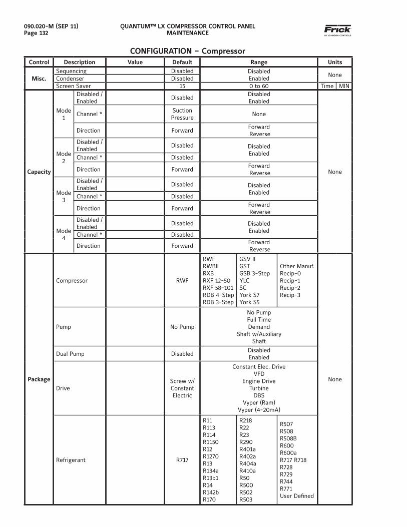
QUANTUM™ LX COMPRESSOR CONTROL PANELMAINTENANCE
090.020-M (SEP 11)Page 132
CONFIGURATION – CompressorControl Description Value Default Range Units
Misc.Sequencing Disabled Disabled
EnabledNone
Condenser DisabledScreen Saver 15 0 to 60 Time MIN
Capacity
Mode1
Disabled / Enabled
DisabledDisabledEnabled
None
Channel *Suction Pressure
None
Direction ForwardForward Reverse
Mode2
Disabled / Enabled
Disabled DisabledEnabled
Channel * Disabled
Direction ForwardForward Reverse
Mode3
Disabled / Enabled
Disabled DisabledEnabled
Channel * Disabled
Direction ForwardForward Reverse
Mode4
Disabled / Enabled
Disabled DisabledEnabled
Channel * Disabled
Direction ForwardForward Reverse
Package
Compressor RWF
RWFRWBIIRXBRXF 12-50RXF 58-101RDB 4-StepRDB 3-Step
GSV IIGSTGSB 3-StepYLCSCYork S7York S5
Other Manuf.Recip-0Recip-1Recip-2Recip-3
None
Pump No Pump
No PumpFull TimeDemand
Shaft w/AuxiliaryShaft
Dual Pump DisabledDisabledEnabled
DriveScrew w/Constant Electric
Constant Elec. DriveVFD
Engine DriveTurbine
DBSVyper (Ram)
Vyper (4-20mA)
Refrigerant R717
R11R113R114R1150R12R1270R13R134aR13b1R14R142bR170
R218R22R23R290R401aR402aR404aR410aR50R500R502R503
R507R508R508BR600R600aR717 R718 R728R729R744R771User Defi ned
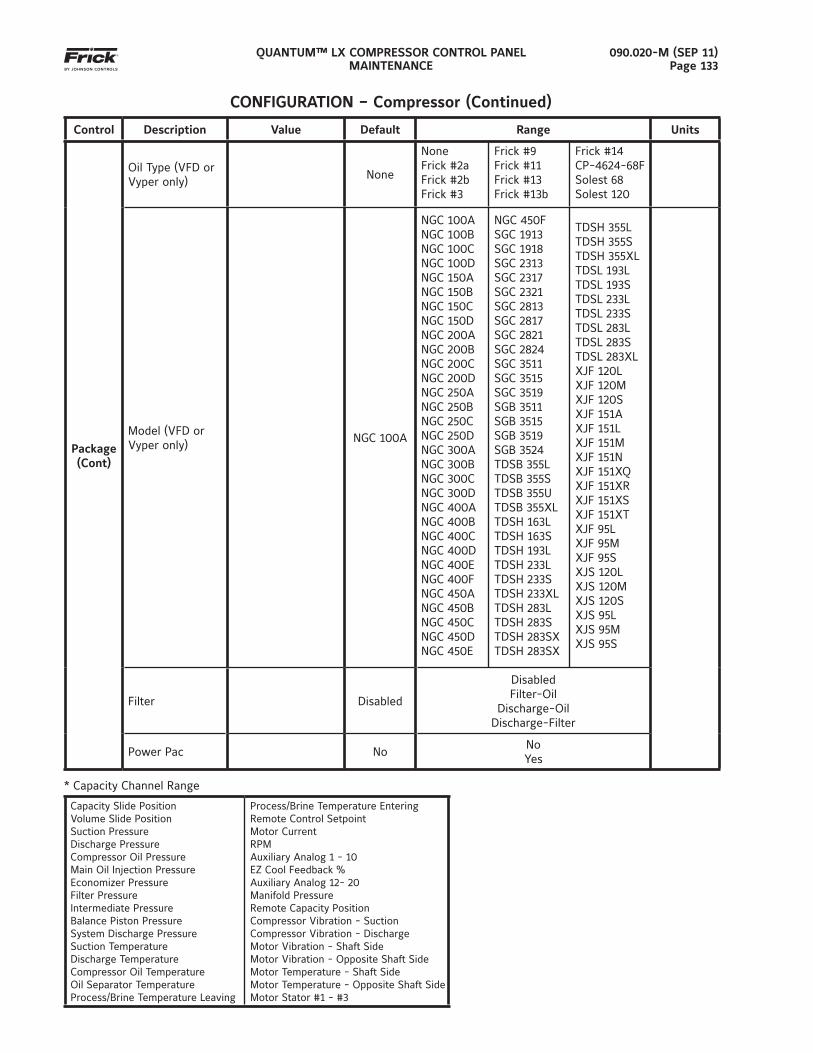
QUANTUM™ LX COMPRESSOR CONTROL PANELMAINTENANCE
090.020-M (SEP 11)Page 133
Control Description Value Default Range Units
Package(Cont)
Oil Type (VFD or Vyper only)
None
NoneFrick #2aFrick #2bFrick #3
Frick #9Frick #11Frick #13Frick #13b
Frick #14CP-4624-68FSolest 68Solest 120
Model (VFD or Vyper only)
NGC 100A
NGC 100ANGC 100BNGC 100CNGC 100D NGC 150ANGC 150BNGC 150CNGC 150DNGC 200ANGC 200BNGC 200CNGC 200DNGC 250ANGC 250BNGC 250CNGC 250DNGC 300ANGC 300BNGC 300CNGC 300DNGC 400ANGC 400BNGC 400CNGC 400DNGC 400ENGC 400FNGC 450ANGC 450BNGC 450CNGC 450DNGC 450E
NGC 450F SGC 1913SGC 1918SGC 2313SGC 2317SGC 2321SGC 2813 SGC 2817SGC 2821SGC 2824SGC 3511SGC 3515SGC 3519SGB 3511SGB 3515SGB 3519SGB 3524TDSB 355LTDSB 355STDSB 355UTDSB 355XLTDSH 163LTDSH 163STDSH 193LTDSH 233LTDSH 233STDSH 233XLTDSH 283LTDSH 283STDSH 283SXTDSH 283SX
TDSH 355L TDSH 355STDSH 355XLTDSL 193LTDSL 193STDSL 233LTDSL 233STDSL 283LTDSL 283STDSL 283XLXJF 120LXJF 120MXJF 120SXJF 151AXJF 151LXJF 151MXJF 151NXJF 151XQXJF 151XRXJF 151XSXJF 151XTXJF 95LXJF 95MXJF 95SXJS 120LXJS 120MXJS 120SXJS 95LXJS 95MXJS 95S
Filter Disabled
DisabledFilter-Oil
Discharge-OilDischarge-Filter
Power Pac NoNoYes
* Capacity Channel Range
Capacity Slide PositionVolume Slide PositionSuction PressureDischarge PressureCompressor Oil PressureMain Oil Injection PressureEconomizer PressureFilter PressureIntermediate PressureBalance Piston PressureSystem Discharge PressureSuction TemperatureDischarge TemperatureCompressor Oil TemperatureOil Separator TemperatureProcess/Brine Temperature Leaving
Process/Brine Temperature EnteringRemote Control SetpointMotor CurrentRPMAuxiliary Analog 1 - 10EZ Cool Feedback %Auxiliary Analog 12- 20Manifold PressureRemote Capacity PositionCompressor Vibration - SuctionCompressor Vibration - DischargeMotor Vibration - Shaft SideMotor Vibration - Opposite Shaft SideMotor Temperature - Shaft SideMotor Temperature - Opposite Shaft SideMotor Stator #1 - #3
CONFIGURATION – Compressor (Continued)
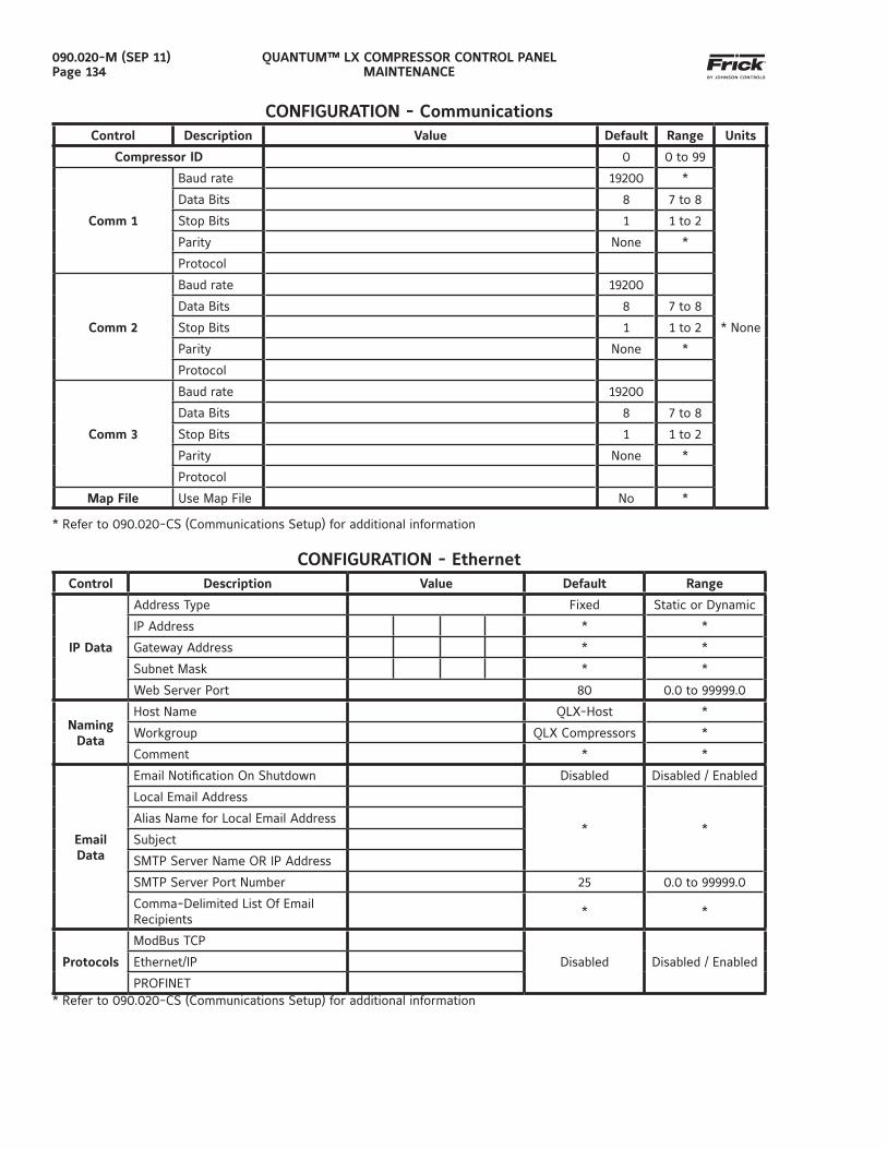
QUANTUM™ LX COMPRESSOR CONTROL PANELMAINTENANCE
090.020-M (SEP 11)Page 134
CONFIGURATION - CommunicationsControl Description Value Default Range Units
Compressor ID 0 0 to 99
* None
Comm 1
Baud rate 19200 *
Data Bits 8 7 to 8
Stop Bits 1 1 to 2
Parity None *
Protocol
Comm 2
Baud rate 19200
Data Bits 8 7 to 8
Stop Bits 1 1 to 2
Parity None *
Protocol
Comm 3
Baud rate 19200
Data Bits 8 7 to 8
Stop Bits 1 1 to 2
Parity None *
Protocol
Map File Use Map File No *
* Refer to 090.020-CS (Communications Setup) for additional information
CONFIGURATION - EthernetControl Description Value Default Range
IP Data
Address Type Fixed Static or Dynamic
IP Address * *
Gateway Address * *
Subnet Mask * *
Web Server Port 80 0.0 to 99999.0
Naming Data
Host Name QLX-Host *
Workgroup QLX Compressors *
Comment * *
Email Data
Email Notifi cation On Shutdown Disabled Disabled / Enabled
Local Email Address
* *Alias Name for Local Email Address
Subject
SMTP Server Name OR IP Address
SMTP Server Port Number 25 0.0 to 99999.0
Comma-Delimited List Of Email Recipients
* *
Protocols
ModBus TCP
Disabled Disabled / EnabledEthernet/IP
PROFINET* Refer to 090.020-CS (Communications Setup) for additional information
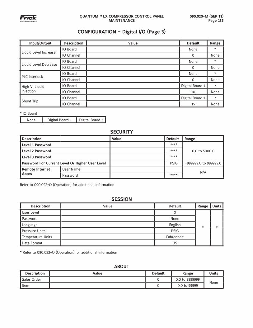
QUANTUM™ LX COMPRESSOR CONTROL PANELMAINTENANCE
090.020-M (SEP 11)Page 135
CONFIGURATION – Digital I/O (Page 3)
Input/Output Description Value Default Range
Liquid Level IncreaseIO Board None *
IO Channel 0 None
Liquid Level DecreaseIO Board None *
IO Channel 0 None
PLC InterlockIO Board None *
IO Channel 0 None
High VI LiquidInjection
IO Board Digital Board 1 *
IO Channel 10 None
Shunt TripIO Board Digital Board 1 *
IO Channel 15 None
* IO Board
None Digital Board 1 Digital Board 2
SECURITYDescription Value Default Range
Level 1 Password ****
0.0 to 5000.0Level 2 Password ****
Level 3 Password ****
Password For Current Level Or Higher User Level PSIG -999999.0 to 999999.0
Remote Internet Acces
User NameN/A
Password ****
Refer to 090.022-O (Operation) for additional information
SESSIONDescription Value Default Range Units
User Level 0
* *
Password None
Language English
Pressure Units PSIG
Temperature Units Fahrenheit
Date Format US * Refer to 090.022-O (Operation) for additional information
ABOUTDescription Value Default Range Units
Sales Order 0 0.0 to 9999999None
Item 0 0.0 to 99999
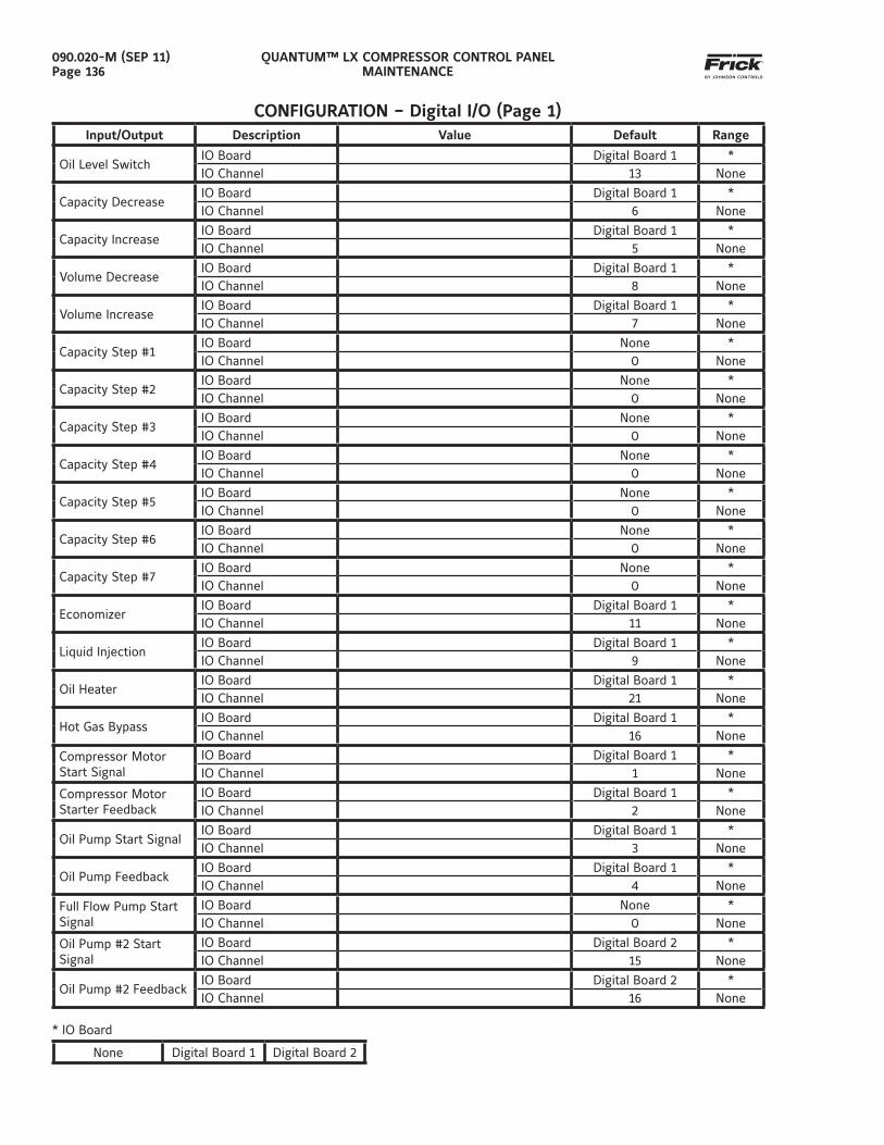
QUANTUM™ LX COMPRESSOR CONTROL PANELMAINTENANCE
090.020-M (SEP 11)Page 136
CONFIGURATION – Digital I/O (Page 1)Input/Output Description Value Default Range
Oil Level SwitchIO Board Digital Board 1 *IO Channel 13 None
Capacity DecreaseIO Board Digital Board 1 *IO Channel 6 None
Capacity IncreaseIO Board Digital Board 1 *IO Channel 5 None
Volume DecreaseIO Board Digital Board 1 *IO Channel 8 None
Volume IncreaseIO Board Digital Board 1 *IO Channel 7 None
Capacity Step #1IO Board None *IO Channel 0 None
Capacity Step #2IO Board None *IO Channel 0 None
Capacity Step #3IO Board None *IO Channel 0 None
Capacity Step #4IO Board None *IO Channel 0 None
Capacity Step #5IO Board None *IO Channel 0 None
Capacity Step #6IO Board None *IO Channel 0 None
Capacity Step #7IO Board None *IO Channel 0 None
EconomizerIO Board Digital Board 1 *IO Channel 11 None
Liquid InjectionIO Board Digital Board 1 *IO Channel 9 None
Oil HeaterIO Board Digital Board 1 *IO Channel 21 None
Hot Gas BypassIO Board Digital Board 1 *IO Channel 16 None
Compressor Motor Start Signal
IO Board Digital Board 1 *IO Channel 1 None
Compressor Motor Starter Feedback
IO Board Digital Board 1 *IO Channel 2 None
Oil Pump Start SignalIO Board Digital Board 1 *IO Channel 3 None
Oil Pump FeedbackIO Board Digital Board 1 *IO Channel 4 None
Full Flow Pump Start Signal
IO Board None *IO Channel 0 None
Oil Pump #2 Start Signal
IO Board Digital Board 2 *IO Channel 15 None
Oil Pump #2 FeedbackIO Board Digital Board 2 *IO Channel 16 None
* IO Board
None Digital Board 1 Digital Board 2
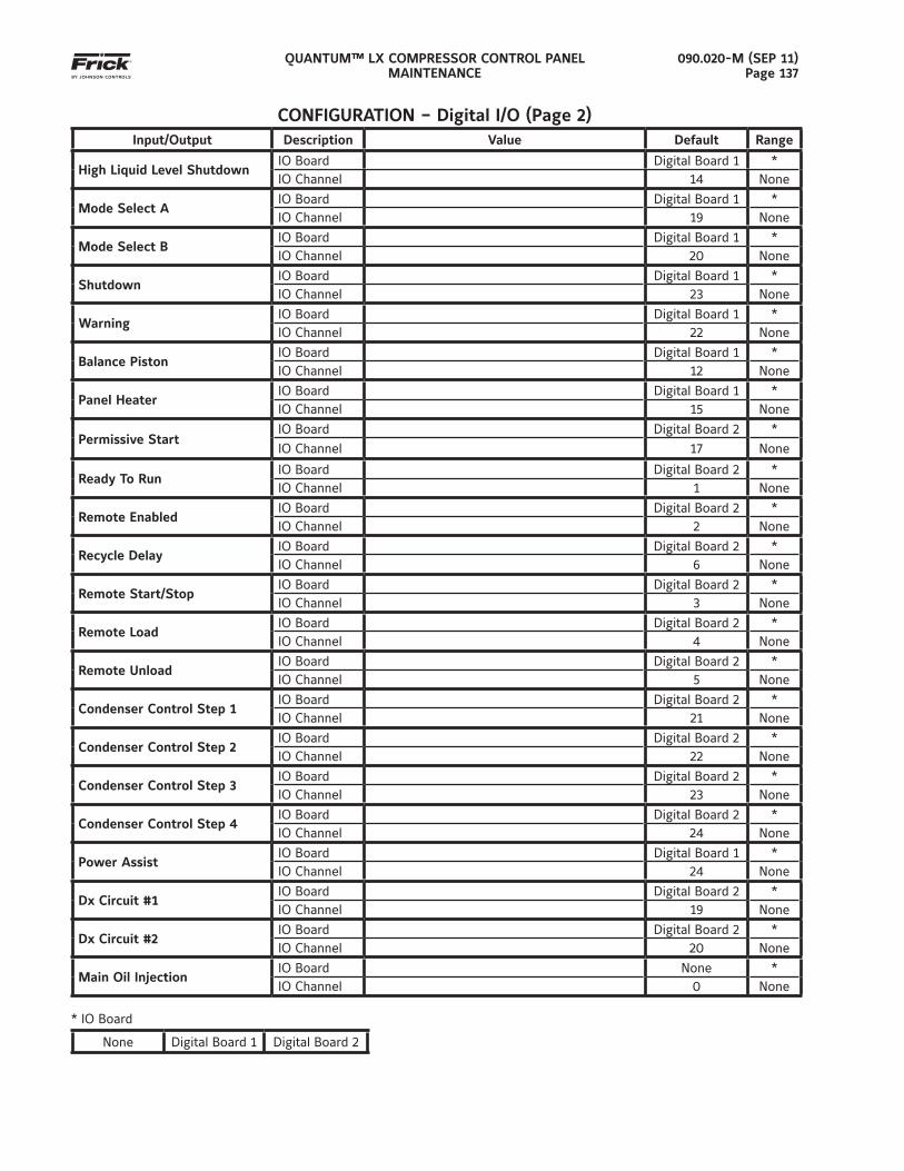
QUANTUM™ LX COMPRESSOR CONTROL PANELMAINTENANCE
090.020-M (SEP 11)Page 137
CONFIGURATION – Digital I/O (Page 2)Input/Output Description Value Default Range
High Liquid Level ShutdownIO Board Digital Board 1 *IO Channel 14 None
Mode Select AIO Board Digital Board 1 *IO Channel 19 None
Mode Select BIO Board Digital Board 1 *IO Channel 20 None
ShutdownIO Board Digital Board 1 *IO Channel 23 None
WarningIO Board Digital Board 1 *IO Channel 22 None
Balance PistonIO Board Digital Board 1 *IO Channel 12 None
Panel HeaterIO Board Digital Board 1 *IO Channel 15 None
Permissive StartIO Board Digital Board 2 *
IO Channel 17 None
Ready To RunIO Board Digital Board 2 *IO Channel 1 None
Remote EnabledIO Board Digital Board 2 *IO Channel 2 None
Recycle DelayIO Board Digital Board 2 *IO Channel 6 None
Remote Start/StopIO Board Digital Board 2 *IO Channel 3 None
Remote LoadIO Board Digital Board 2 *IO Channel 4 None
Remote UnloadIO Board Digital Board 2 *IO Channel 5 None
Condenser Control Step 1IO Board Digital Board 2 *IO Channel 21 None
Condenser Control Step 2IO Board Digital Board 2 *IO Channel 22 None
Condenser Control Step 3IO Board Digital Board 2 *IO Channel 23 None
Condenser Control Step 4IO Board Digital Board 2 *IO Channel 24 None
Power AssistIO Board Digital Board 1 *IO Channel 24 None
Dx Circuit #1IO Board Digital Board 2 *IO Channel 19 None
Dx Circuit #2IO Board Digital Board 2 *IO Channel 20 None
Main Oil InjectionIO Board None *IO Channel 0 None
* IO Board
None Digital Board 1 Digital Board 2

QUANTUM™ LX COMPRESSOR CONTROL PANELMAINTENANCE
090.020-M (SEP 11)Page 138
NOTES:
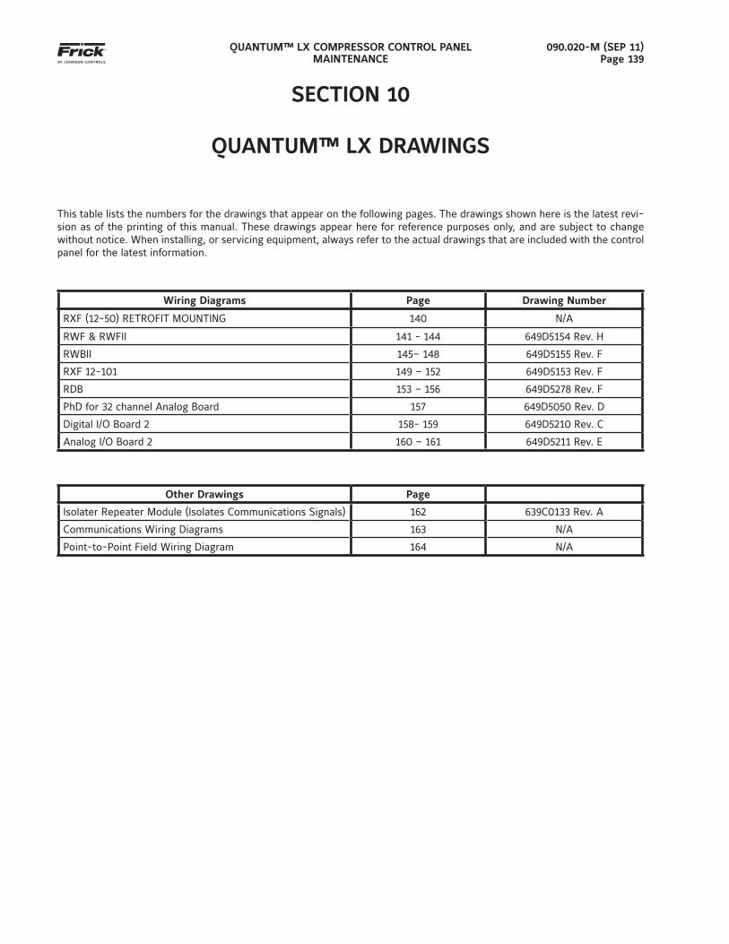
QUANTUM™ LX COMPRESSOR CONTROL PANELMAINTENANCE
090.020-M (SEP 11)Page 139
SECTION 10
QUANTUM™ LX DRAWINGS
This table lists the numbers for the drawings that appear on the following pages. The drawings shown here is the latest revi-sion as of the printing of this manual. These drawings appear here for reference purposes only, and are subject to change without notice. When installing, or servicing equipment, always refer to the actual drawings that are included with the control panel for the latest information.
Wiring Diagrams Page Drawing Number
RXF (12-50) RETROFIT MOUNTING 140 N/A
RWF & RWFII 141 - 144 649D5154 Rev. H
RWBII 145– 148 649D5155 Rev. F
RXF 12-101 149 – 152 649D5153 Rev. F
RDB 153 – 156 649D5278 Rev. F
PhD for 32 channel Analog Board 157 649D5050 Rev. D
Digital I/O Board 2 158- 159 649D5210 Rev. C
Analog I/O Board 2 160 – 161 649D5211 Rev. E
Other Drawings Page
Isolater Repeater Module (Isolates Communications Signals) 162 639C0133 Rev. A
Communications Wiring Diagrams 163 N/A
Point-to-Point Field Wiring Diagram 164 N/A
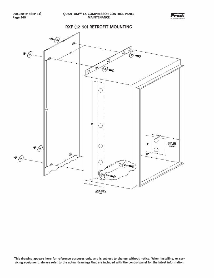
QUANTUM™ LX COMPRESSOR CONTROL PANELMAINTENANCE
090.020-M (SEP 11)Page 140
RXF (12-50) RETROFIT MOUNTING
This drawing appears here for reference purposes only, and is subject to change without notice. When installing, or ser-vicing equipment, always refer to the actual drawings that are included with the control panel for the latest information.
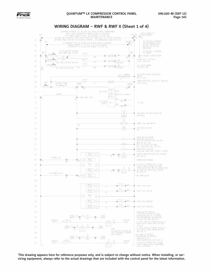
QUANTUM™ LX COMPRESSOR CONTROL PANELMAINTENANCE
090.020-M (SEP 11)Page 141
WIRING DIAGRAM – RWF & RWF II (Sheet 1 of 4)
This drawing appears here for reference purposes only, and is subject to change without notice. When installing, or ser-vicing equipment, always refer to the actual drawings that are included with the control panel for the latest information.
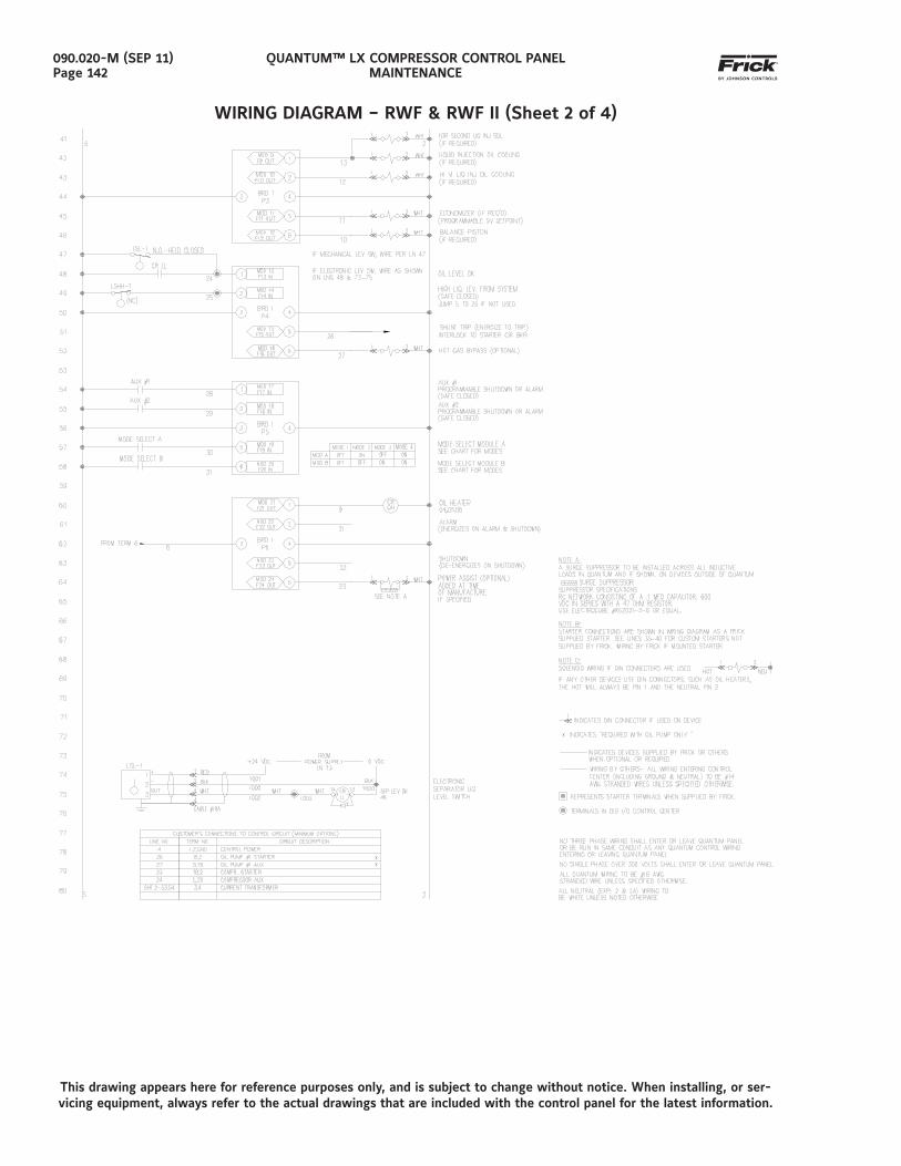
QUANTUM™ LX COMPRESSOR CONTROL PANELMAINTENANCE
090.020-M (SEP 11)Page 142
WIRING DIAGRAM – RWF & RWF II (Sheet 2 of 4)
This drawing appears here for reference purposes only, and is subject to change without notice. When installing, or ser-vicing equipment, always refer to the actual drawings that are included with the control panel for the latest information.
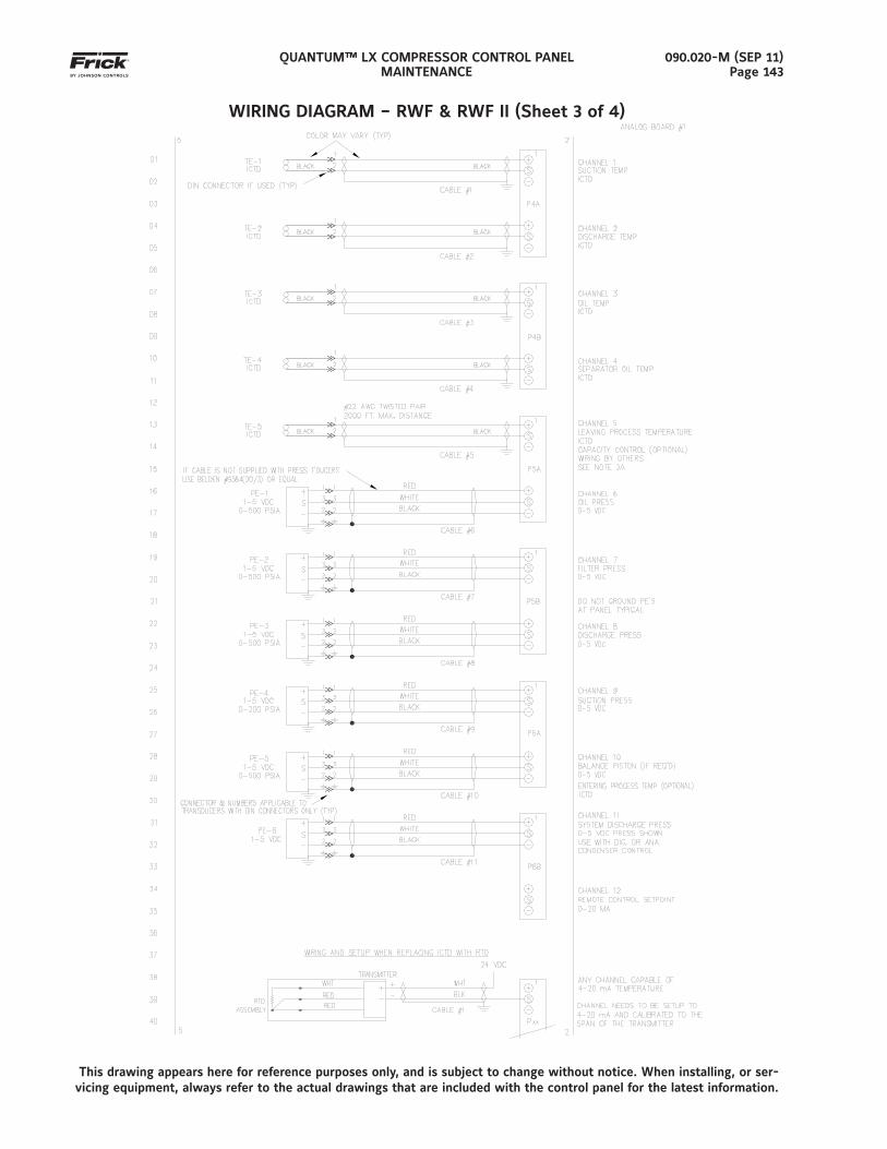
QUANTUM™ LX COMPRESSOR CONTROL PANELMAINTENANCE
090.020-M (SEP 11)Page 143
WIRING DIAGRAM – RWF & RWF II (Sheet 3 of 4)
This drawing appears here for reference purposes only, and is subject to change without notice. When installing, or ser-vicing equipment, always refer to the actual drawings that are included with the control panel for the latest information.
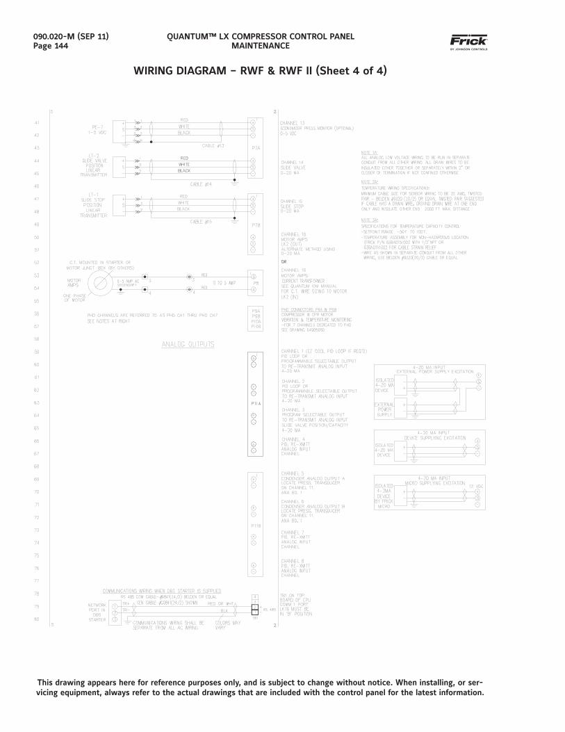
QUANTUM™ LX COMPRESSOR CONTROL PANELMAINTENANCE
090.020-M (SEP 11)Page 144
WIRING DIAGRAM – RWF & RWF II (Sheet 4 of 4)
This drawing appears here for reference purposes only, and is subject to change without notice. When installing, or ser-vicing equipment, always refer to the actual drawings that are included with the control panel for the latest information.
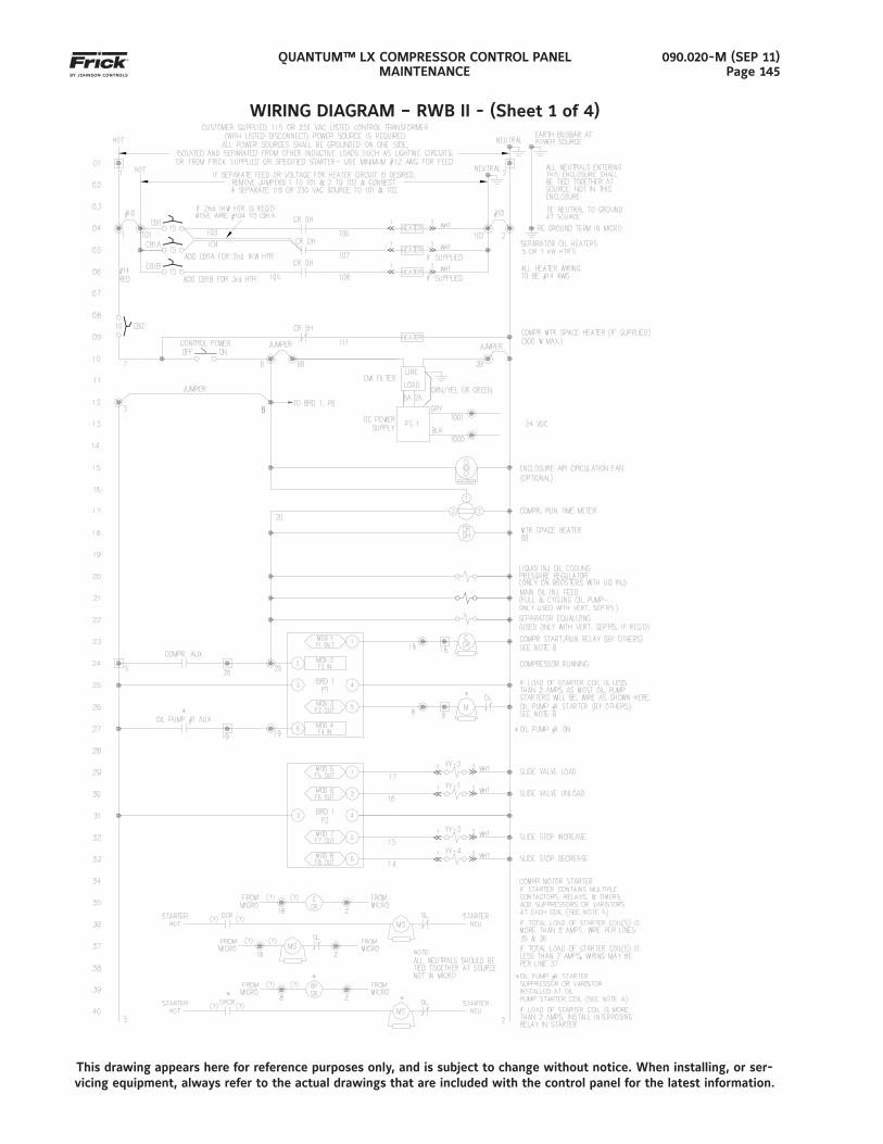
QUANTUM™ LX COMPRESSOR CONTROL PANELMAINTENANCE
090.020-M (SEP 11)Page 145
WIRING DIAGRAM – RWB II - (Sheet 1 of 4)
This drawing appears here for reference purposes only, and is subject to change without notice. When installing, or ser-vicing equipment, always refer to the actual drawings that are included with the control panel for the latest information.
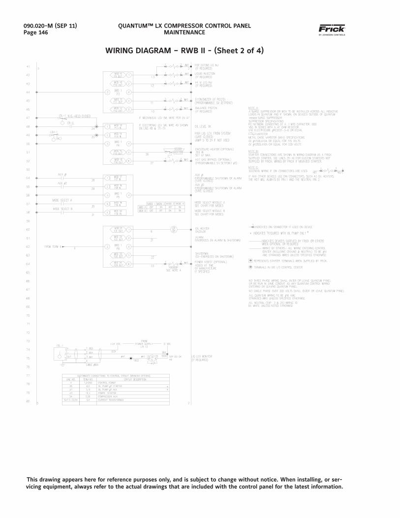
QUANTUM™ LX COMPRESSOR CONTROL PANELMAINTENANCE
090.020-M (SEP 11)Page 146
WIRING DIAGRAM – RWB II - (Sheet 2 of 4)
This drawing appears here for reference purposes only, and is subject to change without notice. When installing, or ser-vicing equipment, always refer to the actual drawings that are included with the control panel for the latest information.
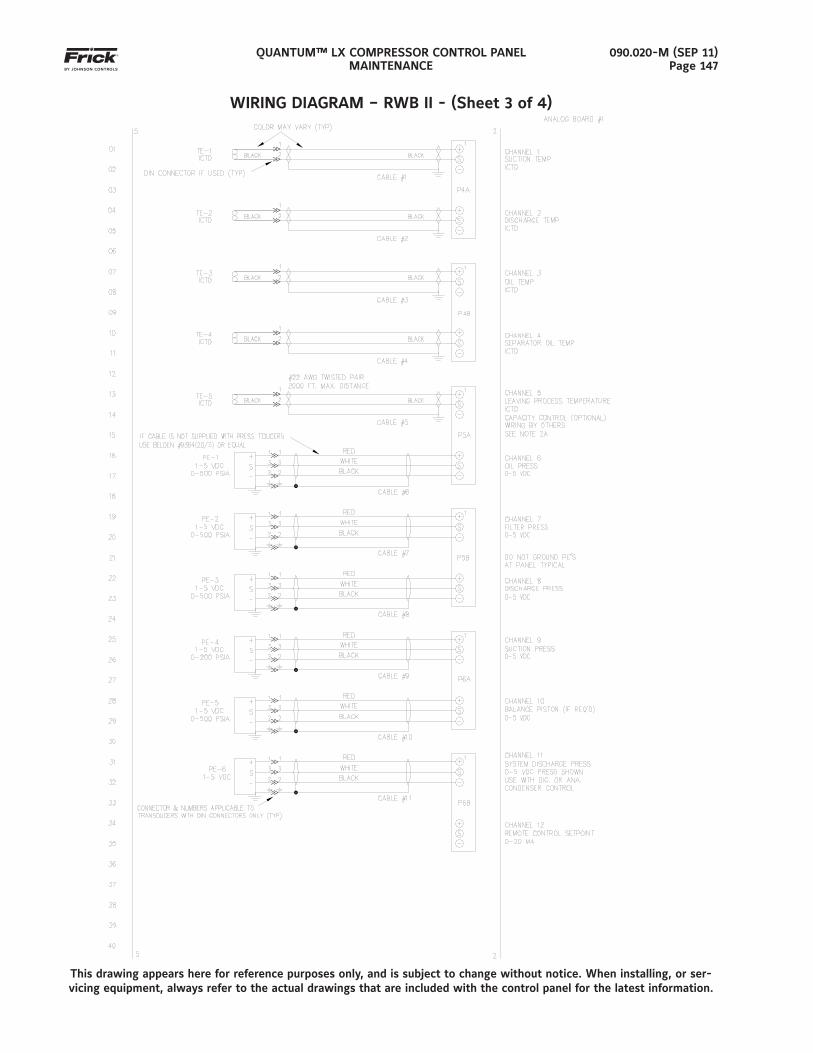
QUANTUM™ LX COMPRESSOR CONTROL PANELMAINTENANCE
090.020-M (SEP 11)Page 147
WIRING DIAGRAM – RWB II - (Sheet 3 of 4)
This drawing appears here for reference purposes only, and is subject to change without notice. When installing, or ser-vicing equipment, always refer to the actual drawings that are included with the control panel for the latest information.
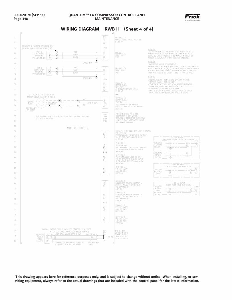
QUANTUM™ LX COMPRESSOR CONTROL PANELMAINTENANCE
090.020-M (SEP 11)Page 148
WIRING DIAGRAM – RWB II - (Sheet 4 of 4)
This drawing appears here for reference purposes only, and is subject to change without notice. When installing, or ser-vicing equipment, always refer to the actual drawings that are included with the control panel for the latest information.
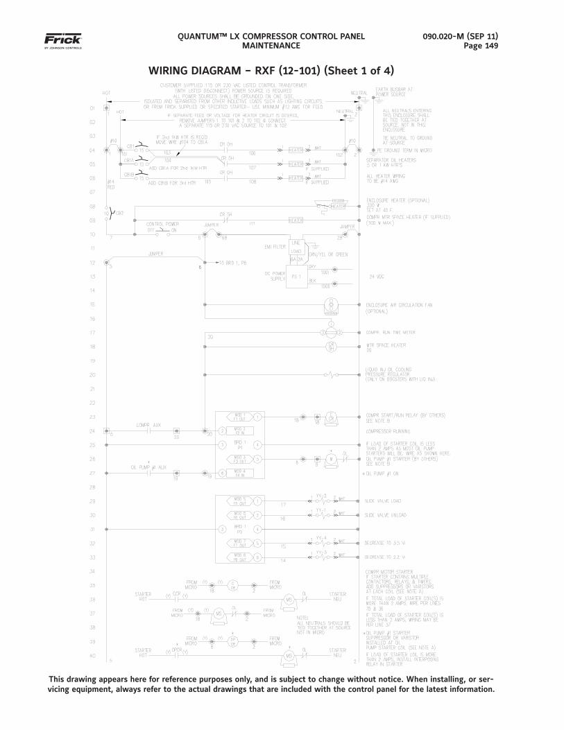
QUANTUM™ LX COMPRESSOR CONTROL PANELMAINTENANCE
090.020-M (SEP 11)Page 149
WIRING DIAGRAM – RXF (12-101) (Sheet 1 of 4)
This drawing appears here for reference purposes only, and is subject to change without notice. When installing, or ser-vicing equipment, always refer to the actual drawings that are included with the control panel for the latest information.
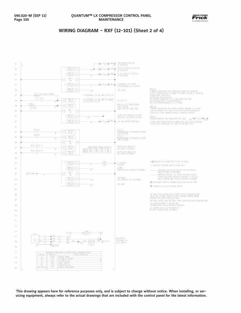
QUANTUM™ LX COMPRESSOR CONTROL PANELMAINTENANCE
090.020-M (SEP 11)Page 150
WIRING DIAGRAM – RXF (12-101) (Sheet 2 of 4)
This drawing appears here for reference purposes only, and is subject to change without notice. When installing, or ser-vicing equipment, always refer to the actual drawings that are included with the control panel for the latest information.
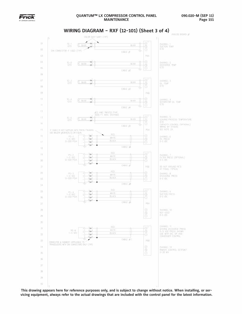
QUANTUM™ LX COMPRESSOR CONTROL PANELMAINTENANCE
090.020-M (SEP 11)Page 151
WIRING DIAGRAM – RXF (12-101) (Sheet 3 of 4)
This drawing appears here for reference purposes only, and is subject to change without notice. When installing, or ser-vicing equipment, always refer to the actual drawings that are included with the control panel for the latest information.
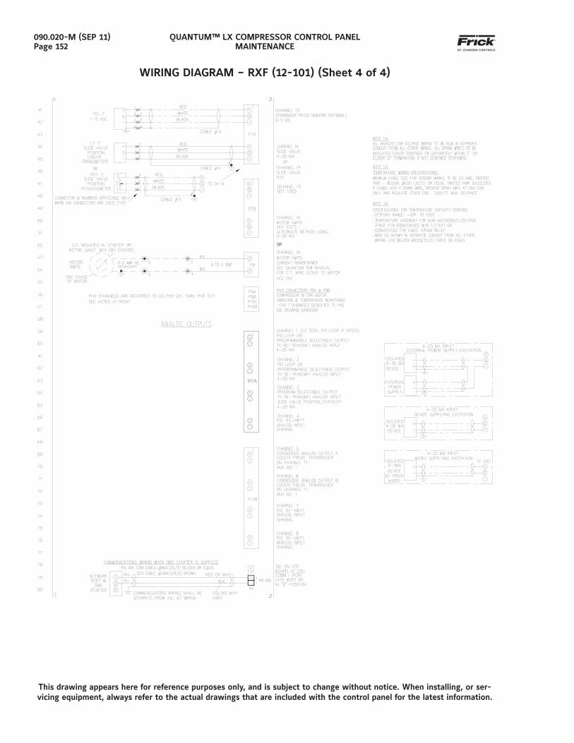
QUANTUM™ LX COMPRESSOR CONTROL PANELMAINTENANCE
090.020-M (SEP 11)Page 152
WIRING DIAGRAM – RXF (12-101) (Sheet 4 of 4)
This drawing appears here for reference purposes only, and is subject to change without notice. When installing, or ser-vicing equipment, always refer to the actual drawings that are included with the control panel for the latest information.
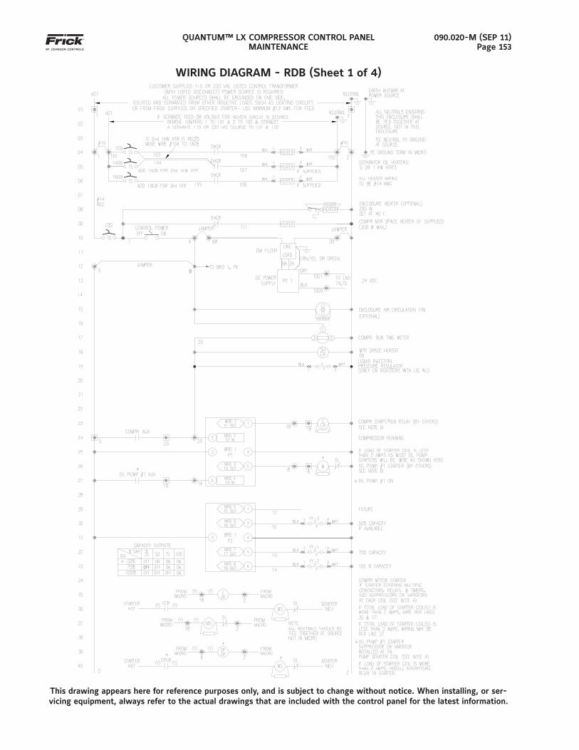
QUANTUM™ LX COMPRESSOR CONTROL PANELMAINTENANCE
090.020-M (SEP 11)Page 153
WIRING DIAGRAM - RDB (Sheet 1 of 4)
This drawing appears here for reference purposes only, and is subject to change without notice. When installing, or ser-vicing equipment, always refer to the actual drawings that are included with the control panel for the latest information.
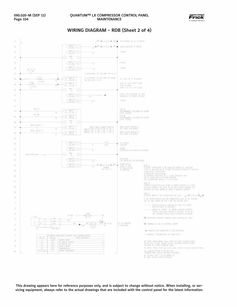
QUANTUM™ LX COMPRESSOR CONTROL PANELMAINTENANCE
090.020-M (SEP 11)Page 154
WIRING DIAGRAM - RDB (Sheet 2 of 4)
This drawing appears here for reference purposes only, and is subject to change without notice. When installing, or ser-vicing equipment, always refer to the actual drawings that are included with the control panel for the latest information.
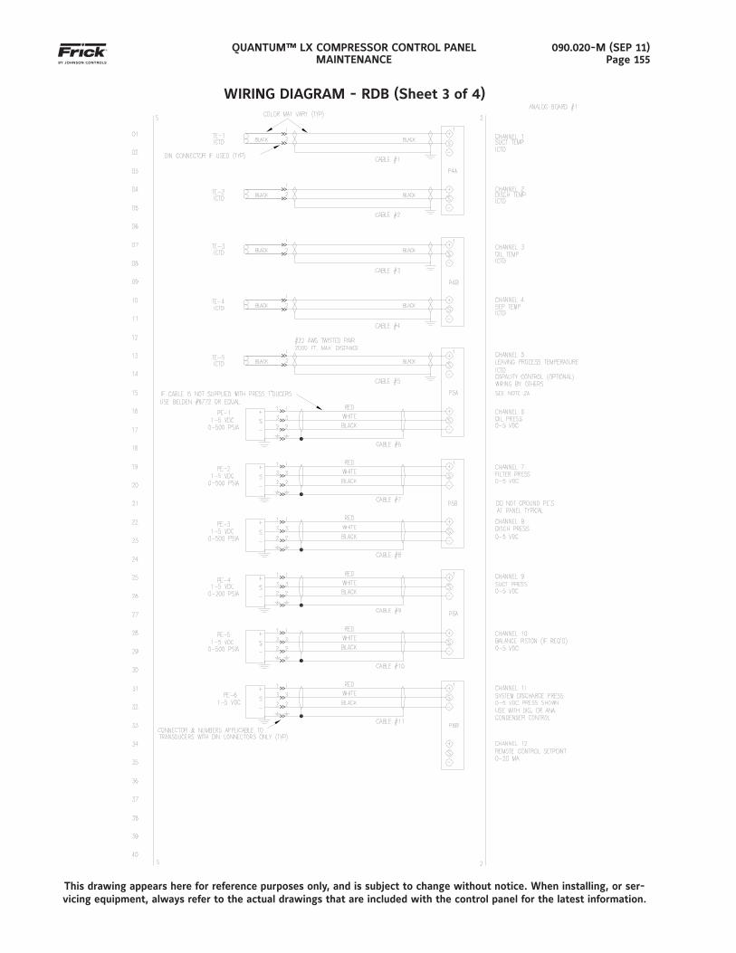
QUANTUM™ LX COMPRESSOR CONTROL PANELMAINTENANCE
090.020-M (SEP 11)Page 155
WIRING DIAGRAM - RDB (Sheet 3 of 4)
This drawing appears here for reference purposes only, and is subject to change without notice. When installing, or ser-vicing equipment, always refer to the actual drawings that are included with the control panel for the latest information.
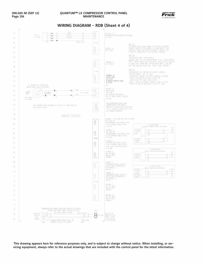
QUANTUM™ LX COMPRESSOR CONTROL PANELMAINTENANCE
090.020-M (SEP 11)Page 156
WIRING DIAGRAM - RDB (Sheet 4 of 4)
This drawing appears here for reference purposes only, and is subject to change without notice. When installing, or ser-vicing equipment, always refer to the actual drawings that are included with the control panel for the latest information.
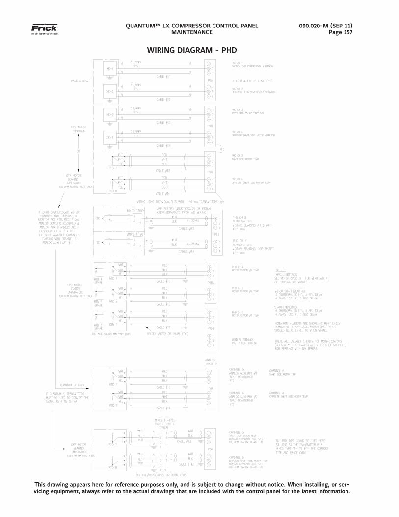
QUANTUM™ LX COMPRESSOR CONTROL PANELMAINTENANCE
090.020-M (SEP 11)Page 157
WIRING DIAGRAM - PHD
This drawing appears here for reference purposes only, and is subject to change without notice. When installing, or ser-vicing equipment, always refer to the actual drawings that are included with the control panel for the latest information.
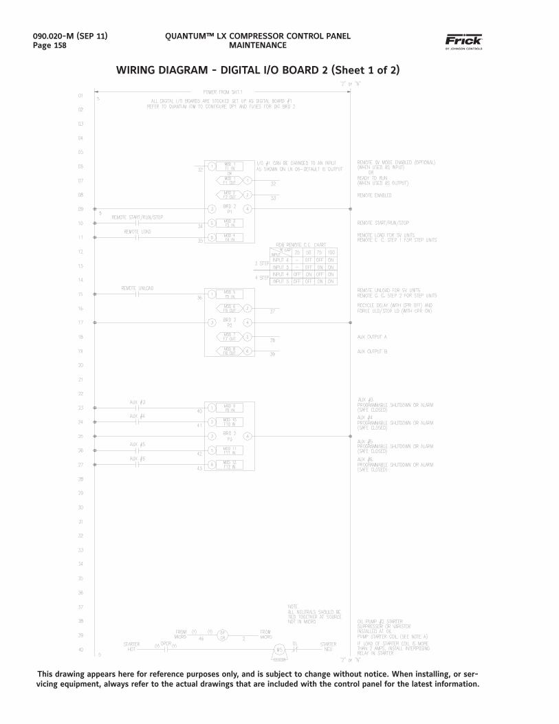
QUANTUM™ LX COMPRESSOR CONTROL PANELMAINTENANCE
090.020-M (SEP 11)Page 158
WIRING DIAGRAM - DIGITAL I/O BOARD 2 (Sheet 1 of 2)
This drawing appears here for reference purposes only, and is subject to change without notice. When installing, or ser-vicing equipment, always refer to the actual drawings that are included with the control panel for the latest information.
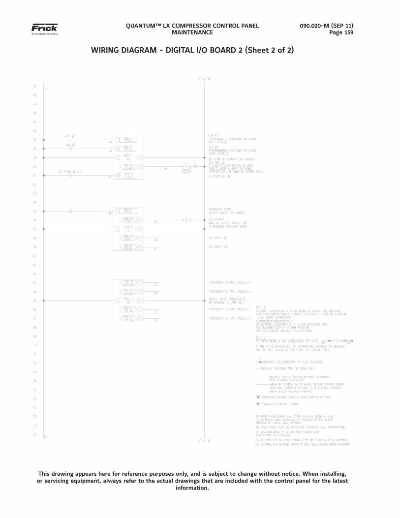
QUANTUM™ LX COMPRESSOR CONTROL PANELMAINTENANCE
090.020-M (SEP 11)Page 159
WIRING DIAGRAM - DIGITAL I/O BOARD 2 (Sheet 2 of 2)
This drawing appears here for reference purposes only, and is subject to change without notice. When installing, or servicing equipment, always refer to the actual drawings that are included with the control panel for the latest
information.
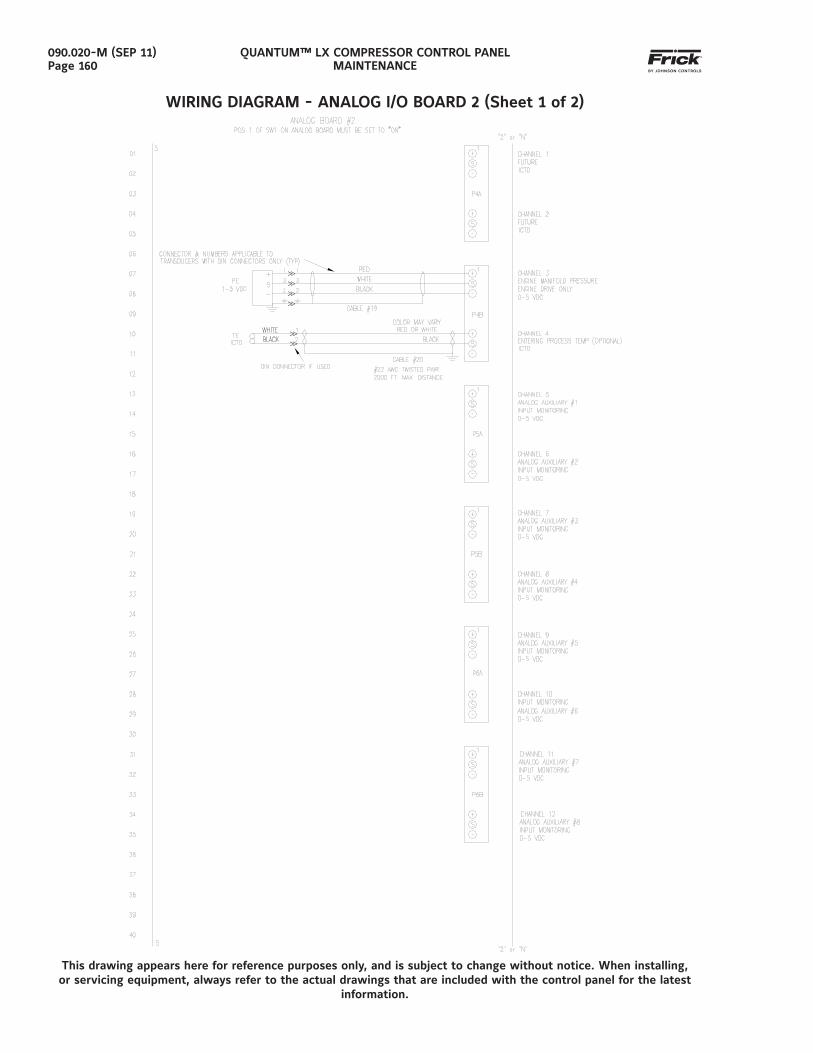
QUANTUM™ LX COMPRESSOR CONTROL PANELMAINTENANCE
090.020-M (SEP 11)Page 160
WIRING DIAGRAM - ANALOG I/O BOARD 2 (Sheet 1 of 2)
This drawing appears here for reference purposes only, and is subject to change without notice. When installing, or servicing equipment, always refer to the actual drawings that are included with the control panel for the latest
information.
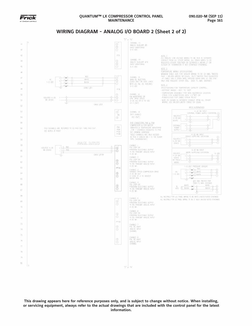
QUANTUM™ LX COMPRESSOR CONTROL PANELMAINTENANCE
090.020-M (SEP 11)Page 161
WIRING DIAGRAM - ANALOG I/O BOARD 2 (Sheet 2 of 2)
This drawing appears here for reference purposes only, and is subject to change without notice. When installing, or servicing equipment, always refer to the actual drawings that are included with the control panel for the latest
information.
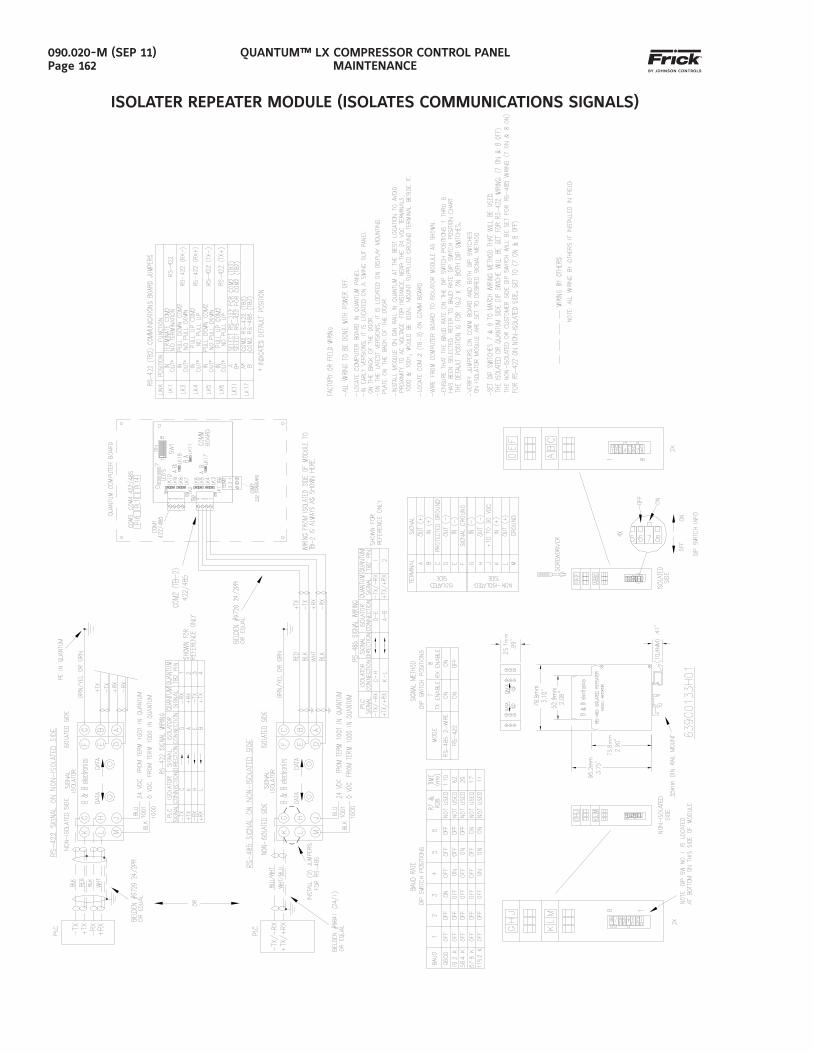
QUANTUM™ LX COMPRESSOR CONTROL PANELMAINTENANCE
090.020-M (SEP 11)Page 162
ISOLATER REPEATER MODULE (ISOLATES COMMUNICATIONS SIGNALS)
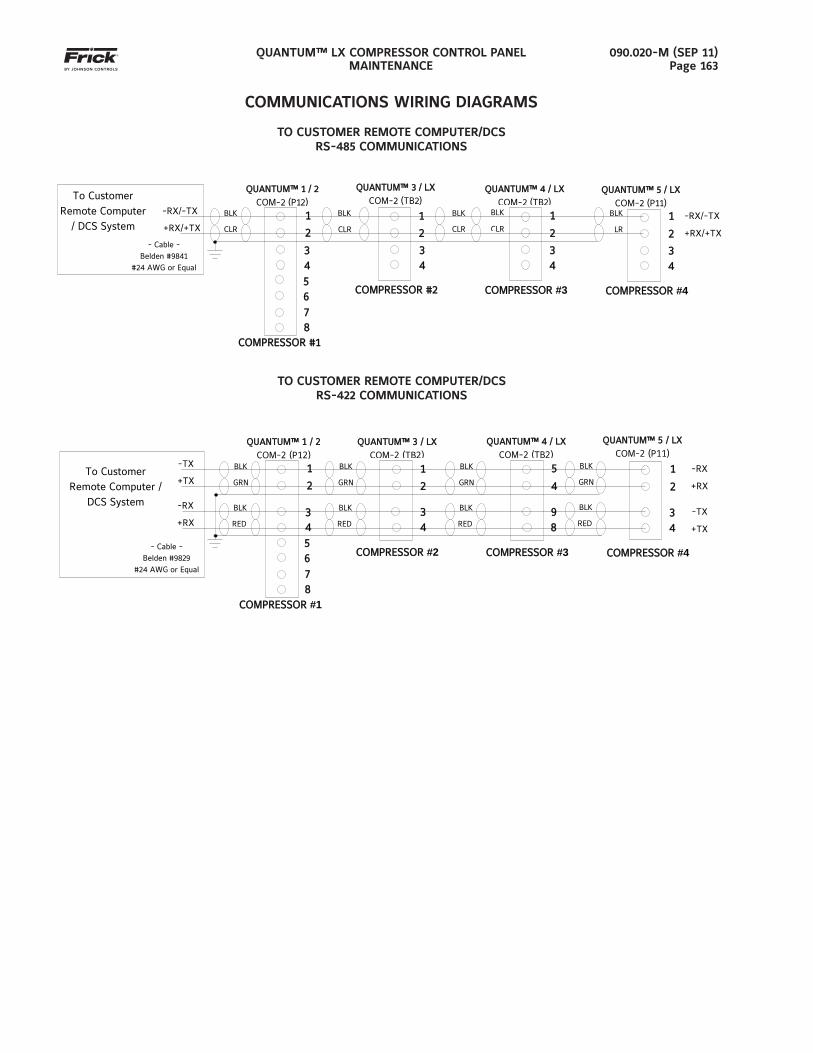
QUANTUM™ LX COMPRESSOR CONTROL PANELMAINTENANCE
090.020-M (SEP 11)Page 163
TO CUSTOMER REMOTE COMPUTER/DCSRS-422 COMMUNICATIONS
COMMUNICATIONS WIRING DIAGRAMS
TO CUSTOMER REMOTE COMPUTER/DCSRS-485 COMMUNICATIONS
5 6
7 8
-TX
+TX
- Cable - Belden #9829
#24 AWG or Equal
To Customer Remote Computer /
DCS System
QUANTUM™ 5 / LX QUANTUM™ 5 / LX
COM-2 (P11)
-RX
+RX -TX
+TX
COMPRESSORCOMPRESSOR #4
QUANTUM™ 1 / 2QUANTUM™ 1 / 2
COM-2 (P12)
COMPRESSORCOMPRESSOR #1
1
2
3 4
1
2
3 4
-RX
+RX
COMPCOMPRESSORRESSOR #2
1
2
3 4
QUANTUM™ 3 / LX QUANTUM™ 3 / LX
COM-2 (TB2)BLK
GRN
BLK
RED
BLK
GRN
BLK
RED
BLK
GRN
BLK
RED
BLK
GRN
BLK
RED
COMPRESSORCOMPRESSOR #3
5
4
9 8
QUANTUM™ 4 / LXQUANTUM™ 4 / LX
COM-2 (TB2)
5 6
7 8
BLK
CLR
COMPRESSORCOMPRESSOR #4
-RX/-TX
+RX/+TX
- Cable - Belden #9841
#24 AWG or Equal
QUANTUM™ 1 / 2QUANTUM™ 1 / 2
COM-2 (P12)
COMPRESSOR #1COMPRESSOR #1
1
2
3 4
BLK
CLR
1
2
3 4
To Customer Remote Computer
/ DCS System -RX/-TX
+RX/+TX
QUANTUM™ QUANTUM™ 55 / LX / LX
COM-2 (P11)
COMPRESSORCOMPRESSOR #3
BLK
CLR
1
2
3 4
QUANTUM™ QUANTUM™ 44 / LX / LX
COM-2 (TB2)BLK
CLR
COMPRESSOR #2COMPRESSOR #2
1
2
3 4
BLK
CLR
QUANTUM™ 3 / LX QUANTUM™ 3 / LX
COM-2 (TB2)
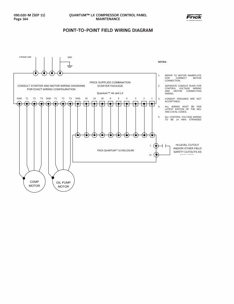
QUANTUM™ LX COMPRESSOR CONTROL PANELMAINTENANCE
090.020-M (SEP 11)Page 164
POINT-TO-POINT FIELD WIRING DIAGRAM
GND T1 T2 T3 GND T1 T2 T3 GND 20 19 18 8 5 4 3 2 1
OIL PUMP MOTOR
COMP MOTOR
CONSULT STARTER AND MOTOR WIRING DIAGRAMS FOR EXACT WIRING CONFIGURATION
FRICK SUPPLIED COMBINATION STARTER PACKAGE
Quantum™ 4A and LX
FRICK QUANTUM™ LX ENCLOSURE
NOTES:
1. REFER TO MOTOR NAMEPLATE FOR CORRECT MOTOR CONNECTION.
2. SEPARATE CONDUIT RUNS FOR
CONTROL VOLTAGE WIRING AND MOTOR CONNECTION WIRING.
3. CONDUIT GROUNDS ARE NOT
ACCEPTABLE. 4. ALL WIRING MUST BE PER
LATEST EDITION OF THE NEC AND LOCAL CODES.
5. ALL CONTROL VOLTAGE WIRING
TO BE 14 AWG STRANDED
HI-LEVEL CUTOUT AND/OR OTHER FIELD SAFETY CUTOUTS AS
REQUIRED
3 PHASE LINE GND
5
25
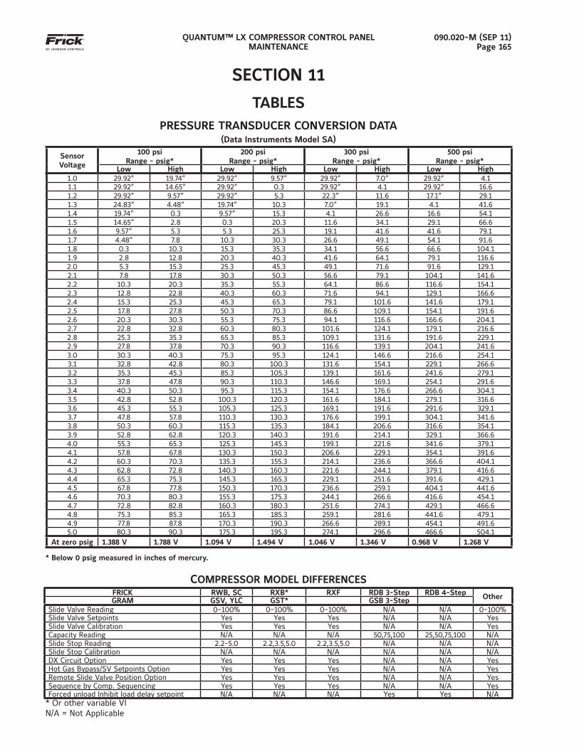
QUANTUM™ LX COMPRESSOR CONTROL PANELMAINTENANCE
090.020-M (SEP 11)Page 165
SECTION 11
TABLESPRESSURE TRANSDUCER CONVERSION DATA
(Data Instruments Model SA)
SensorVoltage
100 psiRange - psig*
200 psiRange - psig*
300 psiRange - psig*
500 psiRange - psig*
Low High Low High Low High Low High1.0 29.92” 19.74” 29.92” 9.57” 29.92” 7.0” 29.92” 4.11.1 29.92” 14.65” 29.92” 0.3 29.92” 4.1 29.92” 16.61.2 29.92” 9.57” 29.92” 5.3 22.3” 11.6 17.1” 29.11.3 24.83” 4.48” 19.74” 10.3 7.0” 19.1 4.1 41.61.4 19.74” 0.3 9.57” 15.3 4.1 26.6 16.6 54.11.5 14.65” 2.8 0.3 20.3 11.6 34.1 29.1 66.61.6 9.57” 5.3 5.3 25.3 19.1 41.6 41.6 79.11.7 4.48” 7.8 10.3 30.3 26.6 49.1 54.1 91.61.8 0.3 10.3 15.3 35.3 34.1 56.6 66.6 104.11.9 2.8 12.8 20.3 40.3 41.6 64.1 79.1 116.62.0 5.3 15.3 25.3 45.3 49.1 71.6 91.6 129.12.1 7.8 17.8 30.3 50.3 56.6 79.1 104.1 141.62.2 10.3 20.3 35.3 55.3 64.1 86.6 116.6 154.12.3 12.8 22.8 40.3 60.3 71.6 94.1 129.1 166.62.4 15.3 25.3 45.3 65.3 79.1 101.6 141.6 179.12.5 17.8 27.8 50.3 70.3 86.6 109.1 154.1 191.62.6 20.3 30.3 55.3 75.3 94.1 116.6 166.6 204.12.7 22.8 32.8 60.3 80.3 101.6 124.1 179.1 216.62.8 25.3 35.3 65.3 85.3 109.1 131.6 191.6 229.12.9 27.8 37.8 70.3 90.3 116.6 139.1 204.1 241.63.0 30.3 40.3 75.3 95.3 124.1 146.6 216.6 254.13.1 32.8 42.8 80.3 100.3 131.6 154.1 229.1 266.63.2 35.3 45.3 85.3 105.3 139.1 161.6 241.6 279.13.3 37.8 47.8 90.3 110.3 146.6 169.1 254.1 291.63.4 40.3 50.3 95.3 115.3 154.1 176.6 266.6 304.13.5 42.8 52.8 100.3 120.3 161.6 184.1 279.1 316.63.6 45.3 55.3 105.3 125.3 169.1 191.6 291.6 329.13.7 47.8 57.8 110.3 130.3 176.6 199.1 304.1 341.63.8 50.3 60.3 115.3 135.3 184.1 206.6 316.6 354.13.9 52.8 62.8 120.3 140.3 191.6 214.1 329.1 366.64.0 55.3 65.3 125.3 145.3 199.1 221.6 341.6 379.14.1 57.8 67.8 130.3 150.3 206.6 229.1 354.1 391.64.2 60.3 70.3 135.3 155.3 214.1 236.6 366.6 404.14.3 62.8 72.8 140.3 160.3 221.6 244.1 379.1 416.64.4 65.3 75.3 145.3 165.3 229.1 251.6 391.6 429.14.5 67.8 77.8 150.3 170.3 236.6 259.1 404.1 441.64.6 70.3 80.3 155.3 175.3 244.1 266.6 416.6 454.14.7 72.8 82.8 160.3 180.3 251.6 274.1 429.1 466.64.8 75.3 85.3 165.3 185.3 259.1 281.6 441.6 479.14.9 77.8 87.8 170.3 190.3 266.6 289.1 454.1 491.65.0 80.3 90.3 175.3 195.3 274.1 296.6 466.6 504.1
At zero psig 1.388 V 1.788 V 1.094 V 1.494 V 1.046 V 1.346 V 0.968 V 1.268 V
* Below 0 psig measured in inches of mercury.
COMPRESSOR MODEL DIFFERENCESFRICK RWB, SC RXB* RXF RDB 3-Step RDB 4-Step OtherGRAM GSV, YLC GST* GSB 3-Step
Slide Valve Reading 0-100% 0-100% 0-100% N/A N/A 0-100%Slide Valve Setpoints Yes Yes Yes N/A N/A YesSlide Valve Calibration Yes Yes Yes N/A N/A YesCapacity Reading N/A N/A N/A 50,75,100 25,50,75,100 N/ASlide Stop Reading 2.2-5.0 2.2,3.5,5.0 2.2,3.5,5.0 N/A N/A N/ASlide Stop Calibration N/A N/A N/A N/A N/A N/ADX Circuit Option Yes Yes Yes N/A N/A YesHot Gas Bypass/SV Setpoints Option Yes Yes Yes N/A N/A YesRemote Slide Valve Position Option Yes Yes Yes N/A N/A YesSequence by Comp. Sequencing Yes Yes Yes N/A N/A YesForced unload Inhibit load delay setpoint N/A N/A N/A Yes Yes N/A
* Or other variable VI N/A = Not Applicable
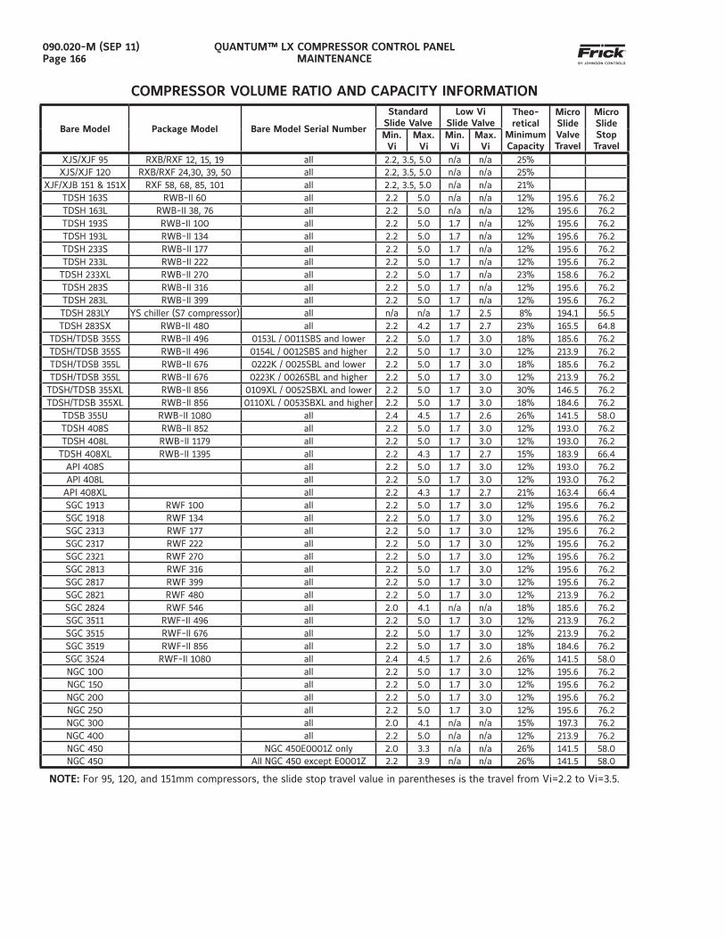
QUANTUM™ LX COMPRESSOR CONTROL PANELMAINTENANCE
090.020-M (SEP 11)Page 166
Bare Model Package Model Bare Model Serial Number
Standard Slide Valve
Low Vi Slide Valve
Theo-retical
Minimum Capacity
Micro Slide Valve Travel
Micro Slide Stop Travel
Min. Vi
Max. Vi
Min. Vi
Max. Vi
XJS/XJF 95 RXB/RXF 12, 15, 19 all 2.2, 3.5, 5.0 n/a n/a 25%XJS/XJF 120 RXB/RXF 24,30, 39, 50 all 2.2, 3.5, 5.0 n/a n/a 25%
XJF/XJB 151 & 151X RXF 58, 68, 85, 101 all 2.2, 3.5, 5.0 n/a n/a 21%TDSH 163S RWB-II 60 all 2.2 5.0 n/a n/a 12% 195.6 76.2TDSH 163L RWB-II 38, 76 all 2.2 5.0 n/a n/a 12% 195.6 76.2TDSH 193S RWB-II 100 all 2.2 5.0 1.7 n/a 12% 195.6 76.2TDSH 193L RWB-II 134 all 2.2 5.0 1.7 n/a 12% 195.6 76.2TDSH 233S RWB-II 177 all 2.2 5.0 1.7 n/a 12% 195.6 76.2TDSH 233L RWB-II 222 all 2.2 5.0 1.7 n/a 12% 195.6 76.2
TDSH 233XL RWB-II 270 all 2.2 5.0 1.7 n/a 23% 158.6 76.2TDSH 283S RWB-II 316 all 2.2 5.0 1.7 n/a 12% 195.6 76.2TDSH 283L RWB-II 399 all 2.2 5.0 1.7 n/a 12% 195.6 76.2TDSH 283LY YS chiller (S7 compressor) all n/a n/a 1.7 2.5 8% 194.1 56.5TDSH 283SX RWB-II 480 all 2.2 4.2 1.7 2.7 23% 165.5 64.8
TDSH/TDSB 355S RWB-II 496 0153L / 0011SBS and lower 2.2 5.0 1.7 3.0 18% 185.6 76.2TDSH/TDSB 355S RWB-II 496 0154L / 0012SBS and higher 2.2 5.0 1.7 3.0 12% 213.9 76.2TDSH/TDSB 355L RWB-II 676 0222K / 0025SBL and lower 2.2 5.0 1.7 3.0 18% 185.6 76.2TDSH/TDSB 355L RWB-II 676 0223K / 0026SBL and higher 2.2 5.0 1.7 3.0 12% 213.9 76.2
TDSH/TDSB 355XL RWB-II 856 0109XL / 0052SBXL and lower 2.2 5.0 1.7 3.0 30% 146.5 76.2TDSH/TDSB 355XL RWB-II 856 0110XL / 0053SBXL and higher 2.2 5.0 1.7 3.0 18% 184.6 76.2
TDSB 355U RWB-II 1080 all 2.4 4.5 1.7 2.6 26% 141.5 58.0TDSH 408S RWB-II 852 all 2.2 5.0 1.7 3.0 12% 193.0 76.2TDSH 408L RWB-II 1179 all 2.2 5.0 1.7 3.0 12% 193.0 76.2
TDSH 408XL RWB-II 1395 all 2.2 4.3 1.7 2.7 15% 183.9 66.4API 408S all 2.2 5.0 1.7 3.0 12% 193.0 76.2API 408L all 2.2 5.0 1.7 3.0 12% 193.0 76.2
API 408XL all 2.2 4.3 1.7 2.7 21% 163.4 66.4SGC 1913 RWF 100 all 2.2 5.0 1.7 3.0 12% 195.6 76.2SGC 1918 RWF 134 all 2.2 5.0 1.7 3.0 12% 195.6 76.2SGC 2313 RWF 177 all 2.2 5.0 1.7 3.0 12% 195.6 76.2SGC 2317 RWF 222 all 2.2 5.0 1.7 3.0 12% 195.6 76.2SGC 2321 RWF 270 all 2.2 5.0 1.7 3.0 12% 195.6 76.2SGC 2813 RWF 316 all 2.2 5.0 1.7 3.0 12% 195.6 76.2SGC 2817 RWF 399 all 2.2 5.0 1.7 3.0 12% 195.6 76.2SGC 2821 RWF 480 all 2.2 5.0 1.7 3.0 12% 213.9 76.2SGC 2824 RWF 546 all 2.0 4.1 n/a n/a 18% 185.6 76.2SGC 3511 RWF-II 496 all 2.2 5.0 1.7 3.0 12% 213.9 76.2SGC 3515 RWF-II 676 all 2.2 5.0 1.7 3.0 12% 213.9 76.2SGC 3519 RWF-II 856 all 2.2 5.0 1.7 3.0 18% 184.6 76.2SGC 3524 RWF-II 1080 all 2.4 4.5 1.7 2.6 26% 141.5 58.0NGC 100 all 2.2 5.0 1.7 3.0 12% 195.6 76.2NGC 150 all 2.2 5.0 1.7 3.0 12% 195.6 76.2NGC 200 all 2.2 5.0 1.7 3.0 12% 195.6 76.2NGC 250 all 2.2 5.0 1.7 3.0 12% 195.6 76.2NGC 300 all 2.0 4.1 n/a n/a 15% 197.3 76.2NGC 400 all 2.2 5.0 n/a n/a 12% 213.9 76.2NGC 450 NGC 450E0001Z only 2.0 3.3 n/a n/a 26% 141.5 58.0NGC 450 All NGC 450 except E0001Z 2.2 3.9 n/a n/a 26% 141.5 58.0
NOTE: For 95, 120, and 151mm compressors, the slide stop travel value in parentheses is the travel from Vi=2.2 to Vi=3.5.
COMPRESSOR VOLUME RATIO AND CAPACITY INFORMATION

QUANTUM™ LX COMPRESSOR CONTROL PANELMAINTENANCE
090.020-M (SEP 11)Page 167
NOTES:

QUANTUM™ LX COMPRESSOR CONTROL PANELMAINTENANCE
090.020-M (SEP 11)Page 168
NOTES:
Form 090.020-M (2011-09)Supersedes: 090-020-M (2011-06)
Subject to change without noticePrinted In USA - GUI 1M .20
2011 Johnson Controls Inc. - ALL RIGHTS RESERVED
JOHNSON CONTROLS100 CV Avenue P.O. Box 997Waynesboro, PA USA 17268-0997Phone: 717-762-2121 FAX: 717-762-8624www.johnsoncontrols.com


![Neuronal intermediate filaments: new progress on an old ......For recent reviews with a more detailed focus on assem- bly properties [2**], cell biology [3**] or phosphorylation](https://img.pdfslide.us/doc/110x75/60427298acd13a11ac30adb5/neuronal-intermediate-filaments-new-progress-on-an-old-for-recent-reviews.jpg)