Embed Size (px)
Citation preview

FPGAs, Scaling and Reliability
Douglas SheldonParts Engineering
Jet Propulsion LaboratoryCalifornia Institute of Technology
Copyright 2009 California Institute of TechnologyMay be published with permission by MAPLD 2009
D. Sheldon - MAPLD 2009
Overview
• Introduction• Scaling Overview• Scaling examples:
– Hot Carrier– Negative Bias Temperature Instability – Package– ESD– FPGA Resources– FPGA Costs
Page 2

D. Sheldon - MAPLD 2009
What do we mean by scaling?
9/1/09 Page 3
Chen IBM 2006

D. Sheldon - MAPLD 20099/1/09 Page 4

D. Sheldon - MAPLD 20099/1/09 Page 5

D. Sheldon - MAPLD 20099/1/09 Page 6

D. Sheldon - MAPLD 2009
Static/Passive Power Problem
9/1/09 Page 7
T. N. Theis IBM 2007

D. Sheldon - MAPLD 2009
Fundamental change over to metal gate devices
9/1/09 Page 8
Chen IBM 2006

D. Sheldon - MAPLD 20099/1/09 Page 9

D. Sheldon - MAPLD 20099/1/09 Page 10
D. Sheldon - MAPLD 20099/1/09 Page 11

D. Sheldon - MAPLD 2009
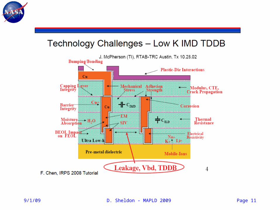
Scaling also means new materials => new reliability challenges
9/1/09 Page 12

D. Sheldon - MAPLD 2009
Modern approach to reliability in scaled devices like FPGAs
Page 139/1/09
V. Huard IRPS 2009 tutorial
Foundry & FPGA vendor
FPGA vendor &
User
D. Sheldon - MAPLD 2009
Scaling Examples
9/1/09 Page 14

D. Sheldon - MAPLD 2009
SiliconBlue FPGAs – NVM via Conductivity Modification – TSMC 65nm
9/1/09 Page 15
http://www.siliconbluetech.com/media/downloads/SBT_65LP_Process_Qual_v0.1.pdf
DC lifetime for Hot Carrier = 0.2yr

D. Sheldon - MAPLD 2009
Is it ok to run my FPGA at a higher than nominal Vdd?
• Example data and models from foundry:
• This example shows a clear reliability issue for that condition.• Manufacturer did additional functional and large sample size HTOL
at 1.2Vdd ± 10% and confirmed 5 year acceptance.• Not acceptable for long term, high reliability space mission.• Scaled technologies have reduced tolerance for “relatively” small
increases in voltage. Designs must have tighter control.
Page 169/1/09
IRPS Tutorial 2009 E. Hnatek and Y.W. Yau

D. Sheldon - MAPLD 2009
Negative Bias Temperature Instability - NBTI
• Complex electro-chemical degradation effect
• Interface trap generation and increased hole trapping mechanisms.
• Some of the degradation is recoverable after the stress is stopped.
• Magnitude of impact depends on circuit topology.
• Digital circuits most effected– Analog circuits will experience
some mismatch
• Both static and dynamic mitigation schemes to compensate for.
Page 179/1/09
A. Krishnan IRPS tutorial 2009

D. Sheldon - MAPLD 2009
NBTI with Xilinx Virtex 4
• DCM (digital clock management) circuits for managing clock skews and delays.– Designed to provide zero propagation delay and low clock skew.
• Accelerated life test show DCM maximum operating frequency will decline if DCM is held in a persistent (non) operating condition.– May not achieve lock at maximum frequency– Static stress creates small variations in duty cycle precision of multi
tap delay lines• Xilinx solutions involve:
– Null designs– Drop in macros for long duration operation– Automatic continuous configuration with updated ISE software
• Device level ageing effects can indeed impact system performance.
Page 189/1/09
http://www.xilinx.com/support/documentation/white_papers/wp224.pdf
http://www.xilinx.com/support/answers/21127.htm

D. Sheldon - MAPLD 2009
Scaling and Packages
• Scaling has significantly increased the the number of pins on modern IC packages.
• Wire bonding has given way to flip chip and wafer bump technologies for increased packing densities
Page 199/1/09

9/1/09 D. Sheldon - MAPLD 2009 20
Xilinx Virtex 2 Package Scaling Anomaly
• Anomaly occurred 28 times during launch level vibration on Y-axis only and did not at levels lower than launch levels
• After much detailed analysis fault identified as CS and RW shorting to together
Work done by JPL Tiger Team with Xilinx support
Scope Trace of Event Occurrences

D. Sheldon - MAPLD 2009
Sample Error Pattern for Anomalous Event
Expected Pattern
Anomalous Pattern
9/1/09 Page 21

Bond wire locations for shorting signals
D. Sheldon - MAPLD 2009 Page 22

9/1/09D. Sheldon - MAPLD 2009
Root Cause – Bond Wire Vibration
• Fundamental mode is a bending side-to-side of the loop
• Depends upon:– Bond wire diameter– Wire to wire spacing– Modulus of Elasticity and density of
material
• High Q~300 can lead to peak-to-peak displacements of a few wire diameters
• Original NASA related work: – M. Blakely, JPL & H. Leidecker, GSFC -
1998
0.151" pad-to-pad wire bond
0
500
1,000
1,500
2,000
2,500
3,000
0.000 0.020 0.040 0.060 0.080
Loop Height [inches]N
atu
ral F
req
ue
nc
y [
Hz]
Observed f
Page 23

D. Sheldon - MAPLD 2009
ESD and scaling
• ESD failures seem independent of HBM performance and device scaling (to first order).
• However scaling (higher speed, lower Vcc, lower breakdown V) makes same historical ESD requirements harder and harder to meet.
• Are historical standards still required?
• Industry council white paper recommends that reduced CDM goals must be adopted to adapt to scaling restrictions.
Page 24White paper 2: Industry Council on ESD Target Levels, 2009
R. Kwasnick, IRPS Tutorial , 2009
D. Sheldon - MAPLD 2009
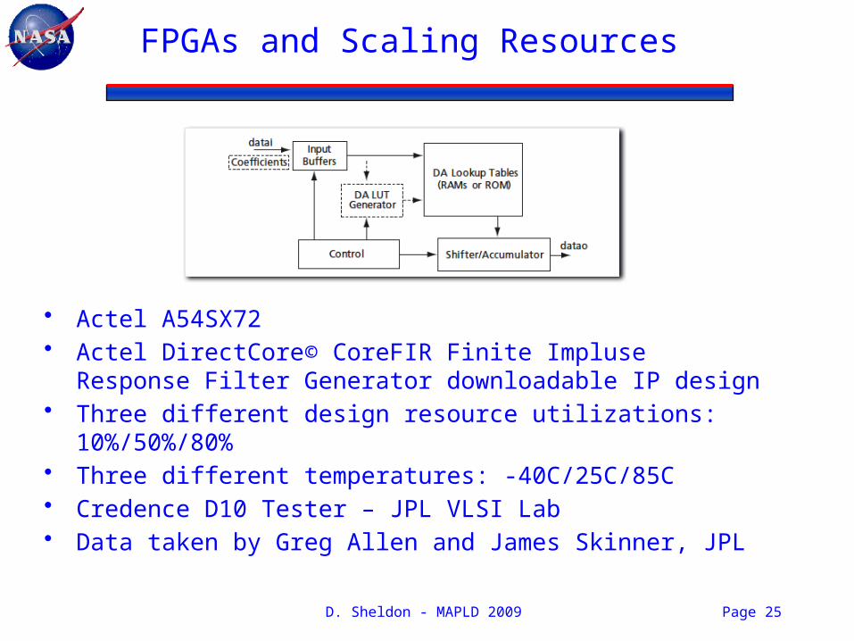
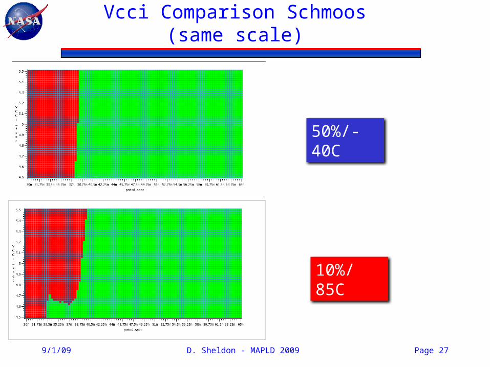
FPGAs and Scaling Resources
• Actel A54SX72• Actel DirectCore© CoreFIR Finite Impluse Response Filter
Generator downloadable IP design• Three different design resource utilizations: 10%/50%/80%• Three different temperatures: -40C/25C/85C• Credence D10 Tester – JPL VLSI Lab• Data taken by Greg Allen and James Skinner, JPL
Page 25

D. Sheldon - MAPLD 2009
Vcca Comparison Schmoos(same scale)
9/1/09 Page 26
50%/25C
80%/85C
D. Sheldon - MAPLD 2009
Vcci Comparison Schmoos(same scale)
9/1/09 Page 27
50%/-40C
10%/85C

D. Sheldon - MAPLD 2009
Timing vs. Temperature - Vcci
• Failing time increases linearly with temperature for designs ≥ 50%
• Increasing % resources used increases the slope of the temperature effect
Page 289/1/09
Nonlinear data

D. Sheldon - MAPLD 2009
Timing vs. Temperature - Vcca
• Increasing utilization increases sensitivity to temperature
• 10% design performance temperature independent
– More robust from reliability/mission assurance
– Small resource (array) contribution to total
• Need to trade mission requirements with reliability requirements
Page 29

D. Sheldon - MAPLD 2009
Scaling and JPL Mars FPGA Cost
Space FPGA cost increase 10X in 10 years
Page 309/1/09

D. Sheldon - MAPLD 2009
Thank you
Page 31