Embed Size (px)
Citation preview

Santa Clara UniversityScholar Commons
Interdisciplinary Design Senior Theses Engineering Senior Theses
6-9-2016
Forge: Thermoelectric CookstoveAustin JacobsSanta Clara University
John MaffeoSanta Clara University
Matt NelsonSanta Clara University
Jared SheehySanta Clara University
Isaac StratfoldSanta Clara University
See next page for additional authors
Follow this and additional works at: https://scholarcommons.scu.edu/idp_senior
This Thesis is brought to you for free and open access by the Engineering Senior Theses at Scholar Commons. It has been accepted for inclusion inInterdisciplinary Design Senior Theses by an authorized administrator of Scholar Commons. For more information, please contact [email protected].
Recommended CitationJacobs, Austin; Maffeo, John; Nelson, Matt; Sheehy, Jared; Stratfold, Isaac; and Ydens, Brad, "Forge: Thermoelectric Cookstove"(2016). Interdisciplinary Design Senior Theses. 18.https://scholarcommons.scu.edu/idp_senior/18

AuthorAustin Jacobs, John Maffeo, Matt Nelson, Jared Sheehy, Isaac Stratfold, and Brad Ydens
This thesis is available at Scholar Commons: https://scholarcommons.scu.edu/idp_senior/18

FORGE:
THERMOELECTRIC COOKSTOVE
By
Austin Jacobs, John Maffeo, Matt Nelson, Jared Sheehy, Isaac Stratfold, Brad Ydens
SENIOR DESIGN PROJECT REPORT
Submitted to The Department of Mechanical Engineering and
Electrical Engineering
of
SANTA CLARA UNIVERSITY
in Partial Fulfillment of the Requirements for the degree of
Bachelor of Science in Mechanical Engineering and
Bachelor of Science in Electrical Engineering
Santa Clara, California
June 9, 2016
iii
ABSTRACT Our interdisciplinary team, known as Forge, has built a cookstove that not only can be a portable
cookstove, but also includes a port to charge devices such as a phone using thermoelectrics. The
product has been designed for developing areas in Nicaragua where power is inaccessible and a
multi-purpose cookstove/phone charger could be of use. The cookstove features a cylindrical
combustion chamber that can be used for gasification. Gasification is a burning process where
smoke from the fire is also burned, creating higher temperatures and a cleaner burn. The
combustion chamber is insulated using refractory cement, which will drop the temperature from
about 700 Celsius inside the chamber to 200 Celsius outside the chamber. The cookstove outputs
heat at a rate of 4.6-6.6 kW. The cookstove has thermoelectric modules attached to the outside,
which, by utilizing the Seebeck effect, convert excess heat into electrical energy. Ideally, the
energy would be transferred into the phone at 5 volts and 0.5-0.6 amps and some of the electrical
energy would be used to power a cooling fan to help the stove function properly. The final
temperatures that were recorded ranged from around 400ºC to 700ºC in the combustion chamber
and around 500ºC for the cooking surface. Gasification was successfully occurring during this
stage, and the smoke was being visibly burned off. The electrical output was less successful,
resulting with only around 0.08 V coming out of the thermoelectric generators due to the lack of
air flow within the electrical housing and poor electrical connection. The stove does achieve its
primary functionality of being more than capable of boiling water, something that presently
available cookstoves in Nicaragua cannot do consistently.

iv
Acknowledgements Team Forge would like to thank many individuals who spent countless hours helping us
complete this project to the best of our ability. We would like to thank Dr. Robert Marks and Dr.
Sally Wood, our advisors, for helping us work on the project through both insight on the subject
and recommendations on how to work successfully as a group. We can’t thank them enough for
the hours they spent meeting with us, making sure we produced the best possible project.
We would also like to thank the School of Engineering for funding us $2500 to create our
project. Without their funding we would not have had the chance to create the prototype we have
been working towards throughout the senior design process.
Several organizations gave us great insight on how we could improve our design, and we
are grateful for each of them. Susan Kinne of Grupo Fenix was very helpful in giving us
information on the market in Nicaragua. Judith Walker of African Clean Energy gave us very
helpful tips on how we can build alternate designs based on what we needed. Lucas Wolf of
Prolena gave us an idea on what the market was for cookstoves in Nicaragua. Each of these
companies were very generous for giving us some of their time and insight and we can’t thank
them enough for doing so.
We would like to thank Opeta Henderson for helping keep track of our budget as we
bought all the parts we need. We would like to thank PWP Manufacturing for helping us
machine the main housing for our project. Finally, we would like to thank Dr. Timothy Hight,
our academic advisor, for helping us stay on track for our project and helping us throughout the
process. We would like to thank everyone who helped us in completing this project.
-Team Forge

v
Table of Contents ABSTRACT..........................................................................................................................iii
Acknowledgements................................................................................................................iv
Chapter 1 - Introduction.......................................................................................................11.1 Background...............................................................................................................................11.2 Related Work.............................................................................................................................11.3 Project Objective.......................................................................................................................4
Chapter 2 - Systems..............................................................................................................62.1 Functional Analysis...................................................................................................................62.2Benchmarked Results................................................................................................................62.3 Customer Needs.........................................................................................................................82.4 Design Safety.............................................................................................................................92.5 System Level Requirements.....................................................................................................102.6 System Sketch with User Scenario...........................................................................................112.7 Team and Project Management...............................................................................................12
Chapter3-Subsystems:CombustionChamber......................................................................133.1 System and Subsystem Layout Design Overview....................................................................133.2 Options and Tradeoffs.............................................................................................................143.3 Detailed Design Description.....................................................................................................153.4 Finite Element Analysis...........................................................................................................153.5 Manufacturing Process............................................................................................................16
Chapter 4 - Subsystems: Thermoelectric Modules..............................................................174.1 Subsystem Requirements.........................................................................................................174.2 Options and Tradeoffs.............................................................................................................184.3 Detailed Design Description.....................................................................................................194.4 Design Drawings......................................................................................................................214.5 Final Project Design and Implementation:..............................................................................23
Part 1..................................................................................................................................................23Part 2..................................................................................................................................................24
Chapter 5: Results................................................................................................................255.1 Results from Combustion Chamber Test................................................................................255.2 Thermoelectric Test Results....................................................................................................29
Chapter 6: Cost Analysis.....................................................................................................32
Chapter 7: Business Plan.....................................................................................................337.1 Executive Summary.................................................................................................................337.2 Introduction.............................................................................................................................337.3 Goals and Objectives...............................................................................................................34

vi
7.4 Description of Product.............................................................................................................357.5 Potential Markets....................................................................................................................367.6 Competition.............................................................................................................................377.7 Sales/Marketing Strategies......................................................................................................397.8 Manufacturing.........................................................................................................................407.9 Product Cost and Price............................................................................................................417.10 Service or Warranties............................................................................................................427.11 Financial Plan and Funding...................................................................................................43
Chapter 8: Engineering Standards......................................................................................488.1 Economic.................................................................................................................................488.2 Environmental.........................................................................................................................488.3 Social & Sustainability.............................................................................................................498.4 Ethical......................................................................................................................................498.5 Health & Safety.......................................................................................................................508.6Arts...........................................................................................................................................50
Chapter 9: Conclusion.........................................................................................................51
Bibliography........................................................................................................................53
APPENDIX A: Team Management......................................................................................1
APPENDIX B: PDS..............................................................................................................1
APPENDIX C: Budget and Timeline....................................................................................1
APPENDIX D: FEA Diagrams and Calculations.................................................................1
APPENDIX E: Detailed Diagrams........................................................................................1
APPENDIX F: Conference Presentation..............................................................................1
APPENDIX G: PWP Test Report.........................................................................................1
vii
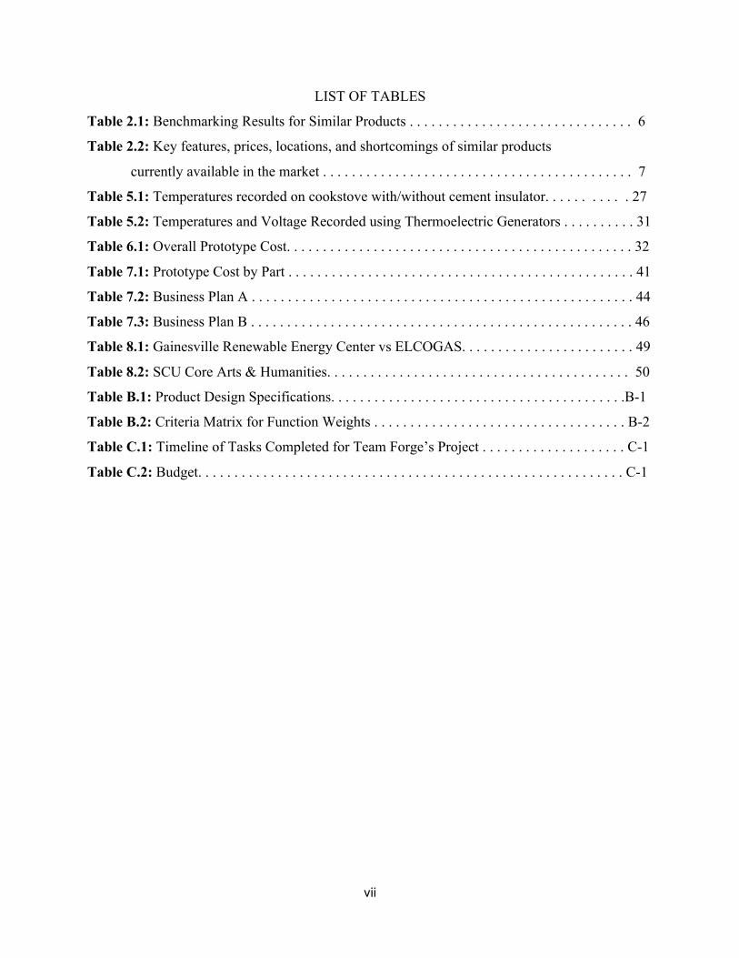
LIST OF TABLES
Table 2.1: Benchmarking Results for Similar Products . . . . . . . . . . . . . . . . . . . . . . . . . . . . . . . 6
Table 2.2: Key features, prices, locations, and shortcomings of similar products
currently available in the market . . . . . . . . . . . . . . . . . . . . . . . . . . . . . . . . . . . . . . . . . . . 7
Table 5.1: Temperatures recorded on cookstove with/without cement insulator. . . . . . . . . . . 27
Table 5.2: Temperatures and Voltage Recorded using Thermoelectric Generators . . . . . . . . . . 31
Table 6.1: Overall Prototype Cost. . . . . . . . . . . . . . . . . . . . . . . . . . . . . . . . . . . . . . . . . . . . . . . . 32
Table 7.1: Prototype Cost by Part . . . . . . . . . . . . . . . . . . . . . . . . . . . . . . . . . . . . . . . . . . . . . . . . 41
Table 7.2: Business Plan A . . . . . . . . . . . . . . . . . . . . . . . . . . . . . . . . . . . . . . . . . . . . . . . . . . . . . 44
Table 7.3: Business Plan B . . . . . . . . . . . . . . . . . . . . . . . . . . . . . . . . . . . . . . . . . . . . . . . . . . . . . 46
Table 8.1: Gainesville Renewable Energy Center vs ELCOGAS. . . . . . . . . . . . . . . . . . . . . . . . 49
Table 8.2: SCU Core Arts & Humanities. . . . . . . . . . . . . . . . . . . . . . . . . . . . . . . . . . . . . . . . . . 50
Table B.1: Product Design Specifications. . . . . . . . . . . . . . . . . . . . . . . . . . . . . . . . . . . . . . . . .B-1
Table B.2: Criteria Matrix for Function Weights . . . . . . . . . . . . . . . . . . . . . . . . . . . . . . . . . . . B-2
Table C.1: Timeline of Tasks Completed for Team Forge’s Project . . . . . . . . . . . . . . . . . . . . C-1
Table C.2: Budget. . . . . . . . . . . . . . . . . . . . . . . . . . . . . . . . . . . . . . . . . . . . . . . . . . . . . . . . . . . C-1
viii
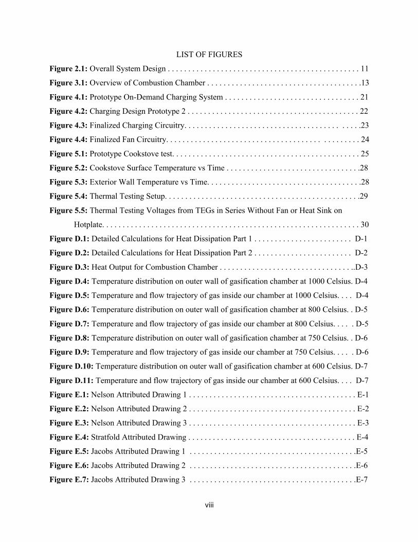
LIST OF FIGURES
Figure 2.1: Overall System Design . . . . . . . . . . . . . . . . . . . . . . . . . . . . . . . . . . . . . . . . . . . . . . . 11
Figure 3.1: Overview of Combustion Chamber . . . . . . . . . . . . . . . . . . . . . . . . . . . . . . . . . . . . . .13
Figure 4.1: Prototype On-Demand Charging System . . . . . . . . . . . . . . . . . . . . . . . . . . . . . . . . . 21
Figure 4.2: Charging Design Prototype 2 . . . . . . . . . . . . . . . . . . . . . . . . . . . . . . . . . . . . . . . . . . 22
Figure 4.3: Finalized Charging Circuitry. . . . . . . . . . . . . . . . . . . . . . . . . . . . . . . . . . . . . . . . . . .23
Figure 4.4: Finalized Fan Circuitry. . . . . . . . . . . . . . . . . . . . . . . . . . . . . . . . . . . . . . . . . . . . . . . 24
Figure 5.1: Prototype Cookstove test. . . . . . . . . . . . . . . . . . . . . . . . . . . . . . . . . . . . . . . . . . . . . . 25
Figure 5.2: Cookstove Surface Temperature vs Time . . . . . . . . . . . . . . . . . . . . . . . . . . . . . . . . .28
Figure 5.3: Exterior Wall Temperature vs Time. . . . . . . . . . . . . . . . . . . . . . . . . . . . . . . . . . . . . .28
Figure 5.4: Thermal Testing Setup. . . . . . . . . . . . . . . . . . . . . . . . . . . . . . . . . . . . . . . . . . . . . . . .29
Figure 5.5: Thermal Testing Voltages from TEGs in Series Without Fan or Heat Sink on
Hotplate. . . . . . . . . . . . . . . . . . . . . . . . . . . . . . . . . . . . . . . . . . . . . . . . . . . . . . . . . . . . . . . 30
Figure D.1: Detailed Calculations for Heat Dissipation Part 1 . . . . . . . . . . . . . . . . . . . . . . . . D-1
Figure D.2: Detailed Calculations for Heat Dissipation Part 2 . . . . . . . . . . . . . . . . . . . . . . . . D-2
Figure D.3: Heat Output for Combustion Chamber . . . . . . . . . . . . . . . . . . . . . . . . . . . . . . . . ..D-3
Figure D.4: Temperature distribution on outer wall of gasification chamber at 1000 Celsius. D-4
Figure D.5: Temperature and flow trajectory of gas inside our chamber at 1000 Celsius. . . . D-4
Figure D.6: Temperature distribution on outer wall of gasification chamber at 800 Celsius. . D-5
Figure D.7: Temperature and flow trajectory of gas inside our chamber at 800 Celsius. . . . . D-5
Figure D.8: Temperature distribution on outer wall of gasification chamber at 750 Celsius. . D-6
Figure D.9: Temperature and flow trajectory of gas inside our chamber at 750 Celsius. . . . . D-6
Figure D.10: Temperature distribution on outer wall of gasification chamber at 600 Celsius. D-7
Figure D.11: Temperature and flow trajectory of gas inside our chamber at 600 Celsius. . . . D-7
Figure E.1: Nelson Attributed Drawing 1 . . . . . . . . . . . . . . . . . . . . . . . . . . . . . . . . . . . . . . . . . E-1
Figure E.2: Nelson Attributed Drawing 2 . . . . . . . . . . . . . . . . . . . . . . . . . . . . . . . . . . . . . . . . . E-2
Figure E.3: Nelson Attributed Drawing 3 . . . . . . . . . . . . . . . . . . . . . . . . . . . . . . . . . . . . . . . . . E-3
Figure E.4: Stratfold Attributed Drawing . . . . . . . . . . . . . . . . . . . . . . . . . . . . . . . . . . . . . . . . . E-4
Figure E.5: Jacobs Attributed Drawing 1 . . . . . . . . . . . . . . . . . . . . . . . . . . . . . . . . . . . . . . . . .E-5
Figure E.6: Jacobs Attributed Drawing 2 . . . . . . . . . . . . . . . . . . . . . . . . . . . . . . . . . . . . . . . . .E-6
Figure E.7: Jacobs Attributed Drawing 3 . . . . . . . . . . . . . . . . . . . . . . . . . . . . . . . . . . . . . . . . .E-7

ix
Figure E.8: Jacobs Attributed Drawing 4 . . . . . . . . . . . . . . . . . . . . . . . . . . . . . . . . . . . . . . . . .E-8
Figure E.9: Sheehy Attributed Drawing 1 . . . . . . . . . . . . . . . . . . . . . . . . . . . . . . . . . . . . . . . . .E-9
Figure E.10: Sheehy Attributed Drawing 2 . . . . . . . . . . . . . . . . . . . . . . . . . . . . . . . . . . . . . . .E-10
Figure E.11: Sheehy Attributed Drawing 3 . . . . . . . . . . . . . . . . . . . . . . . . . . . . . . . . . . . . . . .E-11
Figure E.12: Assembly Drawing . . . . . . . . . . . . . . . . . . . . . . . . . . . . . . . . . . . . . . . . . . . . . . .E-12
Figure E.13: Lower Lid . . . . . . . . . . . . . . . . . . . . . . . . . . . . . . . . . . . . . . . . . . . . . . . . . . . . . E-13
Figure E.14: Base of the Combustion Chamber . . . . . . . . . . . . . . . . . . . . . . . . . . . . . . . . . . . E-14
Figure E.15: Upper Lid . . . . . . . . . . . . . . . . . . . . . . . . . . . . . . . . . . . . . . . . . . . . . . . . . . . . . .E-15
Figure E.16: TEG Holding Apparatus. . . . . . . . . . . . . . . . . . . . . . . . . . . . . . . . . . . . . . . . . . . E-16
Figure F.1: Senior Design Presentation Slides . . . . . . . . . . . . . . . . . . . . . . . . . . . . . . . . . . . . . F-1
Figure G.1: 1008 Cold Rolled Steel Test Report . . . . . . . . . . . . . . . . . . . . . . . . . . . . . . . . . . . G-1

1
Chapter 1 - Introduction
1.1 Background Modernized countries, and citizens within them, have the luxury of fairly simplistic and
uniform methods of providing power to their population. In third-world or developing countries,
the power delivered is restricted to those living in urban environments; this leaves many rural
residents without power. Both Africa and South America have countries in which less than thirty
percent of their citizens have power. The Forge design team seeks an affordable solution to
provide off-grid power for people in developing countries. To do this, Team Forge designed a
cookstove that will both cook food and charge devices. The latter is accomplished by using
thermoelectric modules that convert excess heat into electrical energy.
1.2 Related Work Central and South America was the choice market for our stove, and we specifically
chose Nicaragua because of its low per capita income and high average retail electricity tariff
relative to neighboring countries. Their relative poverty and lack of access to electricity makes
them a perfect target for a product such as ours to create the most impact with our current
specifications and limitations in mind. Furthermore, we were already aware of similar ventures
being conducted in the area, and the design project preceding our own venture targeted
Nicaragua as well, so we knew we would have a plethora of existing resources and information
to work with.
In researching cookstoves currently used in Nicaragua, many were found to come with
various downsides. According to “Who Adopts Improved Fuels and Cookstoves? A Systematic
Review”, by Jessica Lewis and Subhrendu Pattanayak1, most developing countries use fuel
sources such as wood and coal to cook, and about 2 million people die each year from pollutants
1 Lewis and Pattanayak

2
released by inefficient stoves that use these fuels2. This paper stresses two of the biggest
problems we’ll face when building the cookstove: efficiency and safety.
Coal is the biggest producer of airborne pollutants, emitting carbon dioxide, sulfur
dioxide, mercury, and other additional poisons.3 Although this data has been gathered by coal
power plants which produce far more pollution than individual cookstoves, it does show that
there are better options to explore. Dry wood, as a single example, is a better combustible fuel
and is used in many stoves where the dryness of the wood allows for a more thorough burn and
keeps the fuels from jamming and blocking any form of implemented filtration system4.
A previous SCU Senior Design Team attempted to build a thermoelectric cookstove and
faced similar issues with regards to filtering the air pollution. One way our predecessors tried to
limit the pollution was to add a simplistic filtration system, which created a cleaner output as
well as also improving the efficiency5. A filtration system, in order to be considered effective,
needs to filter out combustion particles that are created from burning fuels. A study done by
Stanford engineers6 (the study implemented conditions within the various levels of smog in
China as an extreme point of interest) found a material called polyacrylonitrile to be effective
against smaller smog particles (smaller particles can be more dangerous to the human respiratory
system, due to being able to move outside of the areolae and past natural counter-measures),
Polyacrylonitrile is a rigid thermoplastic that is resistant to most solvents and chemicals, and has
low permeability to gas7.
This may not be the ideal material to use in a filtration system due to its cost, but the
Stanford study does show that there are a variety of materials that can reduce air pollution. These
are noted as well in the study and have been a great help in our research. The previous cookstove
team also found a multipurpose use for the filtration system, which was quite accidental in
development. Along the ventilation shafts, air holes were added to reuse the filtered air to
2 Lewis and Pattanayak 3 Coal Power: Air Pollution 4 Wood Heating and Air Pollution 5 Horman, 25 6 Carey 7 Polyacrylonitrile (PAN) | Chemical Compound

3
oxygenate the combustion chamber, making for a more efficient burning process.8 We have built
upon and improved this design to increase the device’s efficiency.
Similar to the previous process, allowing air to reenter the combustion chamber can
create gasification. This is accomplished if the burn is at a high enough temperature (typically
over 700º Celsius) and if oxygen is forced into the fire. If our cookstove uses this method, the
burn would be more efficient and would not require a filtration system. Due to limited
knowledge about gasification and limited equations, the best way to optimize gasification is
through trial and error. Given our limited knowledge, gasification is the best option since it is
the cleanest burn for the lowest cost.
In order for our project to be successful, the basics of thermodynamics and heat transfer
must also be thoroughly understood in order to achieve an appropriate temperature difference
that could be useful for converting heat into electrical energy. The first thermodynamic law
states that the cyclic integral of the heat transfer is equal to the cyclic integral of the work9.
While this definition may be as simple as work equals heat, it does show that energy in a
substance can be extracted as heat. The heat we generate must also be transferred in our system.
Heat can be transferred by conduction, convection, and/or radiation10. For the sake of simplicity
for our project, conduction and convection will be the two types of heat transfer primarily
utilized, because energy lost as radiation would essentially be reabsorbed by the system and
converted to conduction and/or convection. Both conduction and convection will apply when
heat is escaping our device and reaching the outer surface of the cookstove. In order to have a
reduced temperature on the outer edges of the stove to mitigate burns, a thermally insulating
material can be placed in between the heat source and the outer edges.
Excess heat produced by the stove will also be converted to electricity via thermoelectric
modules that operate under the Seebeck Effect, a corollary to the Peltier effect (which is used in
cooling appliances such as refrigerators). The Seebeck Effect occurs when a temperature
difference between two materials creates a flow of electrons11, thus creating a source of current
which can be harvested and used to power and charge devices. The thermoelectric portion of our
8 Horman 30 9 Borgnakke 342 10 Berman 96 11 Civie

4
stove will not reduce the heat used for the cooking process, but instead uses the conservation of
energy on excess heat to create a large enough voltage and current to charge a mobile phone.
Aside from the technical research on how to make the cookstove function, research was
conducted on Nicaragua, where we are planning to distribute the device. Team Forge so far has
held conference calls with representatives from two companies that are well rooted in the
markets in Nicaragua as well as one company in the cookstove business. The first company we
talked with was Grupo Fenix, a company based in Nicaragua that’s been operating for around 20
years, distributing cookstoves that are essentially boxes with mirrors in them to focus the sun,
and, while providing a large cooking surface, their stoves occasionally fail to reach the boiling
point of water and are quite expensive. We discussed the pros and cons with them regarding their
design, and they agreed that having a cook stove like ours that can reach significantly higher
temperatures than theirs would be ideal. The next company was African Clean Energy, and
although it is based in Africa, it has a very similar product to our own that uses gasification to
burn their fuel. They gave us a few ideas including using refractory ceramics as the heat
shielding within the burn chamber, and the idea of having a licensee for the product to make the
product more affordable in our target market. Our final contact was with Proleña, a company in
Nicaragua that sells basic ceramic stoves for rural villages. They gave us information regarding
the fuel sources used as well as information including the types of food cooked, how it is
prepared, and how it’s stored. This information will be discussed later on.
1.3 Project Objective The Forge team wants to build a functional thermoelectric cookstove that can be
marketed in a third-world country, specifically Nicaragua. It is worth noting that this is the third
time this project has been worked on. Team Matador completed the most recent design three
years ago. They improved upon the first design by making their design more robust combustion
chamber and a more efficient, cleaner burn. Our design will build off Team Matador’s design
and attempt to make it smaller (optimally having a cooking surface being a foot in diameter),
cheaper, and aesthetically pleasing. The design will be built efficiently, ethically, and frugally;
all components needed for a successful third-world country project. As mentioned, our hope is
that our cookstove can be marketed in Nicaragua. If we can not accomplish a fully functional
prototype, we hope that the project will be built efficiently enough where a future senior design

5
group can finish it and market it. As a team, we hope we can learn how to use the design process
to build a functional cookstove that can help the greater good.

6
Chapter 2 - Systems
2.1 Functional Analysis The primary function of our project will be to cook something, or the ability to boil water
by having the cooking surface reach at least 100º Celsius. The secondary function of our device
will be the ability to generate electricity during the cooking process. Our stove will require fuel
and oxygen as basic inputs to function, while cookware and raw food will be required to meet its
primary function. The stove will output heat from the cooking surface and electricity generated
by the thermoelectric system. Our product will be constrained by the availability of the inputs
required for it to function, as well as the necessity of a safe operating environment.
2.2 Benchmarked Results
Table 2.1: Benchmarking Results for Similar Products
Team Forge’s cookstove has numerous competitors that have also created similar
products. One of these products is from African Clean Energy, named the ACE 1 Cookstove, a
cookstove that can generates energy using an optional solar power as an accessory. The product
is the biggest competitor in terms of design, as they produce gasification. The solar energy is also
used to charge cellular devices. The product is marketable in areas where solar energy is easy to
access.

7
Team Matador, the previous senior design project, constructed a cookstove that also
targeted Nicaragua for marketing. The cookstove has a large cooking surface to service an entire
village. It has an efficient burn and has a relatively large heat output. The cookstove has
thermoelectric modules attached to it, but does not create enough voltage to charge a phone. The
product costs $300. The cookstove is also heavy, weighing approximately 45 kg.
BioLite makes a cookstoves that also harvests energy using a thermoelectric generator.
The excess energy can be used for lights, charging devices, and powering internal fans. The cook
stoves are primarily designed for campers who will be away from electricity. The basic
cookstove that BioLite sells costs a realistic $130, marketed to campers.
Table 2.2: Key features, prices, locations, and shortcomings of similar products currently
available in the market.
Company Product Price Distribution Key Features Areas for
Improvement
African
Clean
Energy
ACE 1 $150 Africa Gasification,
Solar panel,
USB
charging
Decrease cost
Team
Matador
Matador $300 Nicaragua TEG’s, large
cooking
surface
Efficiency in
circuits
BioLite BioLite
Campstove
$130 Worldwide Small, USB
charging,
open fire
Increase
efficiency of fire,
include cooking
surface
After consulting multiple companies in similar areas of the business, we have created a
benchmark from which to build off of. Starting with the pricing, the price range for similar
devices is around $150 - $200. Team Matador designed a product that cost $300. Taking all of
8
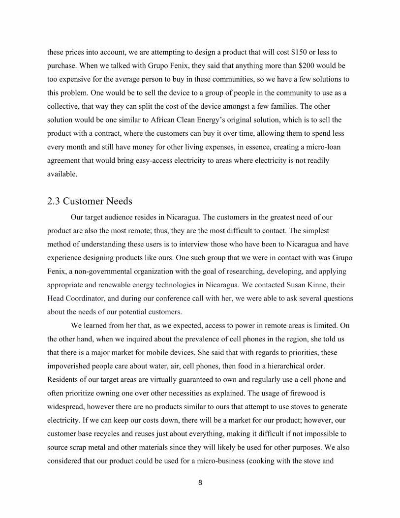
these prices into account, we are attempting to design a product that will cost $150 or less to
purchase. When we talked with Grupo Fenix, they said that anything more than $200 would be
too expensive for the average person to buy in these communities, so we have a few solutions to
this problem. One would be to sell the device to a group of people in the community to use as a
collective, that way they can split the cost of the device amongst a few families. The other
solution would be one similar to African Clean Energy’s original solution, which is to sell the
product with a contract, where the customers can buy it over time, allowing them to spend less
every month and still have money for other living expenses, in essence, creating a micro-loan
agreement that would bring easy-access electricity to areas where electricity is not readily
available.
2.3 Customer Needs Our target audience resides in Nicaragua. The customers in the greatest need of our
product are also the most remote; thus, they are the most difficult to contact. The simplest
method of understanding these users is to interview those who have been to Nicaragua and have
experience designing products like ours. One such group that we were in contact with was Grupo
Fenix, a non-governmental organization with the goal of researching, developing, and applying
appropriate and renewable energy technologies in Nicaragua. We contacted Susan Kinne, their
Head Coordinator, and during our conference call with her, we were able to ask several questions
about the needs of our potential customers.
We learned from her that, as we expected, access to power in remote areas is limited. On
the other hand, when we inquired about the prevalence of cell phones in the region, she told us
that there is a major market for mobile devices. She said that with regards to priorities, these
impoverished people care about water, air, cell phones, then food in a hierarchical order.
Residents of our target areas are virtually guaranteed to own and regularly use a cell phone and
often prioritize owning one over other necessities as explained. The usage of firewood is
widespread, however there are no products similar to ours that attempt to use stoves to generate
electricity. If we can keep our costs down, there will be a market for our product; however, our
customer base recycles and reuses just about everything, making it difficult if not impossible to
source scrap metal and other materials since they will likely be used for other purposes. We also
considered that our product could be used for a micro-business (cooking with the stove and

9
supplying power to others for a fee), but we learned that there was a similar attempt with limited
success.
The last major aspect that we learned from our interviews was to pay specific attention to
the types of foods the locals eat, as well as the way they prepare the food. Our contact with
African Clean Energy told us that they were originally thinking about spreading to Peru, but
decided to cancel the entire operation simply because one of the local Peruvian food staples
could not be prepared using their stove. With this information, we decided to incorporate a
modular cooking surface for our stove, which would allow the preparation of a variety of foods
they eat, including the preparation of rice, beans, and tortillas. With this new design, we can have
a flat cooking surface, an open flame, or a stand that would allow consumers to use their own
pots and pans.
2.4 Design Safety During the design process, many aspects were evaluated in order to make the best
possible product we can make. The most important thing our group focused on was the safety of
our design. The cook stove’s customers will not have a technical background and may easily
make mistakes while using our product. Team Forge designed the cookstove with the goal of
keeping customers safe while simultaneously serving their needs. Reliability is deeply valued in
our product for the same reason safety is valued in our cookstove. The cook stove must be easy
to use and work every time in order for our customers to truly utilize its features. If not, the
product will not be used, even if they have a need for its use. The third aspect of great
importance is the cost of our product. Our team is working on improving Team Matador’s
design, and making the cookstove cheaper will allow us to compete with other products. Team
Forge aims for a product to cost about $150, similar to that of African Clean Energy’s cookstove.
There are other attributes that are not as important as the ones already listed, but which
are still desirable for Team Forge’s optimal design. For instance, the cookstove must achieve a
certain heat and power output for it to be utilized to its fullest potential. Similarly, the aesthetic,
ergonomics, and usability of the cookstove needs to be taken into account. The cook stove
designed by Team Matador was rather large for its general purpose, so Team Forge has designed
our cookstove to be smaller and more portable. This change is also due to the product being

10
marketed at a significantly lower price than Team Matador’s product. While the criteria listed
are important, the criteria that will greatly benefit the cookstove are safety, reliability, and cost.
2.5 System Level Requirements Certain requirements need to be met when designing our product, but more importantly,
we need to decide which requirements should be the main focus for our design and functionality.
Regarding these issues, we created a criterion matrix which looks at each aspect of the device
and compares it to the others to rank them in order of what we believe to be the most important
function, and what could be ignored while in production. After compiling the matrix, it was
determined that safety is of the utmost priority, with reliability coming second, since reliability is
closely intertwined with safety as we don’t want the stove to fail when the customer is using it.
Cost follows this, since we wouldn’t be able to distribute this device if no one could buy it. Next
comes the functions of the device: heat output, power output, and the usability. And finally
comes size and then weight. We deemed weight to be the least important factor, since although it
could be portable, all other criteria were of higher value than the weight, including the size,
which is controlled by the type of cooking needed.

11
2.6 System Sketch with User Scenario The system level sketch shows the basic operation and function of the cookstove.
The system level sketch above outlines the three major processes at work when using our
cookstove design. The first step requires the procurement and insertion of biomass into the
cookstove’s burn chamber. For its use in Nicaragua, the majority of biomass collected will be
scrap/forest wood. After the biomass has been properly inserted into the burn chamber, the user
can proceed to step two: ignition. In the ignition step, the system is powered on, and the biomass
has been ignited within the burn chamber using a match, lighter, or other product. The system
then burns until gasification occurs. Once the gasification of the system is considered self-
sustaining (the released synthetic gas is reignited at the top by the fire), the user moves to step
three: cooking and charging. Finally, the user places his or her cookware atop the cookstove.
Additionally, the user may plug in a cell phone or other portable device to the USB port to be
charged.
Figure 2.1: Overall System Design

12
2.7 Team and Project Management In designing this product, many safety hazards can occur for both Team Forge and
possible customers Exposure to the higher temperatures within the cook stove, up to 700º C, is
one of the most significant risks. Safety guidelines will be provided with the product to ensure no
customer comes in contact with the combustion chamber while in use. Finally, the wiring will be
contained internally, so customers will only be exposed to an external USB charging port. The
safety guidelines will also include cautions with regards to the voltage and current produced by
the thermoelectric modules.

13
Chapter 3 - Subsystems: Combustion Chamber
Figure 3.1: Overview of Combustion Chamber
3.1 System and Subsystem Layout Design Overview The combustion subsystem of our device is divided into four main sections, which are the
refractory insulation, the combustion chamber itself, the gas flow chamber, and the outer casing.
The refractory insulation is the first thing the heat from the burning biomass comes in contact
with, and it serves to insulate the metal walls of the chamber by reflecting heat back into it. The
combustion chamber itself contains the burning fuel and the refractory cement cylinder and has
inlet and outlet ports at the bottom and top, respectively, to allow synthetic gas to enter and exit
the flow chamber. The flow chamber itself is an air gap between the combustion chamber and
the outer wall of the device. This gap reduces the heat transfer from the combustion chamber to
the casing, adding further insulation between the burning fuel and the user, and provides a

14
cylindrical channel for the synthetic gas to flow to the top of the stove for reignition. The final
section of the combustion subsystem is the outer casing, the top of which provides a hot surface
at the top to cook. This section also encompasses the electronics and other components while
providing a structurally sound and aesthetically pleasing form factor.
3.2 Options and Tradeoffs Many different design options exist for this project, and there are tradeoffs associated
with each design decision. Aspects such as material choice, housing design, cooling subsystem
design, and electronic component design all factor into the design’s ergonomics, size, portability,
functionality, cost, and other criteria. It is important then, to acknowledge and analyze the
tradeoffs associated with different design choices. The cylindrical housing design was chosen to
maximize airflow and enable gasification. Other housing designs were considered, such as the
use of a rectangular casing that would allow for better packing efficiency and easier
manufacturing, however this design did not allow for adequate internal flow. Additionally, the
use of a cylindrical design versus a rectangular one minimizes the amount of material used,
which reduces the overall weight of the device.
The flow subsystems required a great deal of consideration. In order to maintain a high
temperature difference between the sides of the thermoelectric generator, our primary design
uses a fan to force air over a heat sink in contact with the cold side of the thermoelectric
generator. This provides a cheaper solution, in terms of required materials and input power, than
other active cooling solutions like liquid cooling. This method is likely not as efficient as liquid
cooling, however, in the interest of keeping the cost low, we decided to use a heat sink. To drive
the flow inside the housing for gasification, a simple axial computer fan was chosen. Off the
shelf computer fans have high market availability, low cost, and ability to drive our system with
low-power requirements for high efficiency models. Alternative radial fan designs are available
that would be more efficient, but would likely require more design work to create shrouding. In
addition, the added costs to procure and develop a radial fan would make it impractical for use in
our project.
15
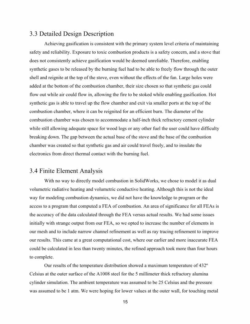
3.3 Detailed Design Description Achieving gasification is consistent with the primary system level criteria of maintaining
safety and reliability. Exposure to toxic combustion products is a safety concern, and a stove that
does not consistently achieve gasification would be deemed unreliable. Therefore, enabling
synthetic gases to be released by the burning fuel had to be able to freely flow through the outer
shell and reignite at the top of the stove, even without the effects of the fan. Large holes were
added at the bottom of the combustion chamber, their size chosen so that synthetic gas could
flow out while air could flow in, allowing the fire to be stoked while enabling gasification. Hot
synthetic gas is able to travel up the flow chamber and exit via smaller ports at the top of the
combustion chamber, where it can be reignited for an efficient burn. The diameter of the
combustion chamber was chosen to accommodate a half-inch thick refractory cement cylinder
while still allowing adequate space for wood logs or any other fuel the user could have difficulty
breaking down. The gap between the actual base of the stove and the base of the combustion
chamber was created so that synthetic gas and air could travel freely, and to insulate the
electronics from direct thermal contact with the burning fuel.
3.4 Finite Element Analysis With no way to directly model combustion in SolidWorks, we chose to model it as dual
volumetric radiative heating and volumetric conductive heating. Although this is not the ideal
way for modeling combustion dynamics, we did not have the knowledge to program or the
access to a program that computed a FEA of combustion. An area of significance for all FEAs is
the accuracy of the data calculated through the FEA versus actual results. We had some issues
initially with strange output from our FEA, so we opted to increase the number of elements in
our mesh and to include narrow channel refinement as well as ray tracing refinement to improve
our results. This came at a great computational cost, where our earlier and more inaccurate FEA
could be calculated in less than twenty minutes, the refined approach took more than four hours
to complete.
Our results of the temperature distribution showed a maximum temperature of 432º
Celsius at the outer surface of the A1008 steel for the 5 millimeter thick refractory alumina
cylinder simulation. The ambient temperature was assumed to be 25 Celsius and the pressure
was assumed to be 1 atm. We were hoping for lower values at the outer wall, for touching metal

16
at a temperature this high even for a short period of time would cause serious injury to the user.
These high temperatures are likely due to the fact that we considered the flame to be uniformly at
1000º Celsius. Realistically our flame will only reach this temperature at the core of the burning
fuel and will become much cooler towards the top. As seen in Figure D.4, the temperature
gradient varies with distance along the y-axis (towards the top of the model). This was expected,
since the alumina layer on the inside only covers some of the combustion chamber. Figure D.5
details the flow within our cookstove. The dark red cylinder in the center represents the
combustion, and the colored lines are flow trajectories moving through the model. The boundary
conditions were set so that flow could enter the model at the base and leave at the top. The flow
simulation matches our understanding of gasified flow behavior.
3.5 Manufacturing Process The combustion chamber and outer casing are two different sections of the same physical
part. The entire metal structure is made of cold formed 1008 sheet steel that has been rolled and
cut into the correct shapes. Holes were drilled into the combustion chamber before assembly, and
then the combustion chamber tube, top casing ring, combustion chamber bottom, outer casing
bottom, and outer casing tube were all welded together. The refractory cylinder was cast in a
cylindrical mold using a mix of 4 parts powdered cement to 1 part water. This was cured for
approximately 24 hours, and then removed and placed into the stove. The first firing of the
cylinder had to be done slowly due to residual water inside the cylinder that could potentially
cause it to crack. After firing, the prototype combustion subsystem of the cookstove was
considered complete.
17
Chapter 4 - Subsystems: Thermoelectric Modules
4.1 Subsystem Requirements There are a few questions that must be addressed and answered before moving on with
the project as it stands; namely, “Why do we need or want electrical power for this device at all?
Wouldn’t a solar array, or any other form of alternate energy, be easier to maintain and utilize?”
We can start with the first question. The first functionality of the device is a design for a
cookstove that reduces toxic/dangerous emissions from current cooking processes used in rural
areas (namely, Nicaragua, where we based most of our research and resources). The newest
venture of the project was to also use the ideas present from previous implementations of the
project12 as well as a devoted electrical engineer to troubleshoot and devise a way to more
efficiently transfer heat into useable electricity. The second question on the choice of alternate
energy sources is also a phenomenal question that we pored over in an effort to get the most
‘Bang for our Buck’. We found that other forms of power production were unsuitable for our
project for multiple reasons: Solar panels were very negatively impacted by large amounts of
heat that would be generated by the device… and the distance between the stove and the solar
panels would make the design into two separate projects (making our attempt at power
generation in our device redundant); where charging a device with USB at times that the
cookstove was not in operation would be a waste of effort as well as a source of issues that could
arise from having sensitive solar components close to a heat source that they were not designed
for. Any form of thermal wind made by the stove would not be enough to power a turbine of
enough size to be worthwhile at the scale we designed, and thinner blades for a small thermal
gust fan run the risk of melting and/or halting the gasification process. Other concepts like solar
devices would not be capable of charging phones at night, which led to thermoelectric
converters, and more specifically, to an implementation of Peltier/Seebeck devices, which has an
advantage over ACE’s product.
Our design’s power production comes from the electrical effect documented as the
Peltier/Seebeck effect, which states that an electrical difference in materials is correlated with a
gradient in temperature. 12 Horman 31

18
𝐸"#$ = −𝑆 ∙ ∇𝑇 Equation (4.1) This equation states that a voltage (E) is generated by a difference in temperatures
multiplied by a constant (S) based on the materials being used.
The Peltier effect is very commonly used throughout the world as a cooling system, with
a supplied current and voltage creating a temperature difference that is used to maintain
temperatures for many applications ranging from use in technical labs to mini-fridges in college
dorms. One of the problematic issues that we found as we progressed with the project is that
almost all documented information regarding these thermoelectric phenomena are described in
terms of the Peltier effect, but the inverse Seebeck effect is peculiarly under-researched. Though
this was an initial setback, we did find that the data used for the Peltier effect was similar to the
data we needed for the Seebeck effect if the power is corrected by reducing it fifteen to twenty
percent.
TEC1-12706, a generic module which costs about $2.00 per unit, uses the Peltier effect.
We used these devices for their low cost and lengthy lifetime (tested at 200,000 hours of usage).
They show, through an albeit confusing way, that the power used at specific voltages and
currents generates specific output temperature differences. In the same way, we used the
differences in temperature to generate power that we used within the project.
With the power generated with these TEGs, we chose to implement a design (based on
previous discussions with potential users in Nicaragua) with an output power in accordance with
USB 2.0 standards (5V, .5 amps). We will also discuss the option of replacing the USB output
with a larger battery system, in case of alternate needs.
4.2 Options and Tradeoffs With cost being one of our primary design criteria, a viable electrical source option for
our system was to use a simple Peltier unit (earlier referenced as a TEC1-12706) in an inverted
format in order to have a cheap Seebeck unit, meaning that instead of powering up the unit with
current and voltage to create a temperature difference we used a temperature difference to
generate voltage and current. This allowed us to cheaply and easily procure an electrical source
that also gave us a multitude of testing and implementation variations such as connecting several
devices serially to generate high voltage, multiple in parallel for high current, and combinations
of the two for desired output current and power levels. One of the limits we worked under with
19
the TEG’s was the internal temperature maximum, since some of the components would melt at
138º C. We found that the best temperature difference for safety of the TEGs and continuous use
of the stove would be in a range of 35 centigrade to 60 centigrade. With further testing, we found
that these temperatures gave us a voltage of 1.2 - 1.9 volts and .46 - .6 amps. We will expand
upon the importance of this within the detailed description.
A circuit known as a Buck-Boost converter was also used in order to maintain a voltage
of 5V for our USB charging output. The Buck-Boost converter was acquired from Linear. We
looked at multiple different implementations that we could use with no outside help, but decided
to go with the advice of experts in the field. Our attempts at a scaled down version, aimed at
multiple different end results, are added below.
4.3 Detailed Design Description The intricacies of our design can be partitioned into three major components: the TEG’s,
the circuitry necessary to regulate the power generated by the TEGs, and the USB standard that
we are delivering the power to.
The TEGs are fairly simplistic in design, with two alumina ceramic plates sandwiching
the semiconductors soldered together with bismuth-tin. This makes the TEG’s very stable and
durable, unless they are exposed to temperatures higher than 138 centigrade.
The second portion pertains to the circuitry, which is comprised of soldered connections
to the TEGs and the Buck-Boost converter we acquired from Linear Tech (LTM8045, PDF is in
the appendix and hyper linked here: http://cds.linear.com/docs/en/datasheet/8032fg.pdf ). The
Buck-Boost converter allows us to make sure variations in voltage and current from the TEGs
are changed into a constant output that we desire in order to meet specifications of USB 2.0. This
circuit has the ability to increase or decrease the voltage using a conversion of the current if the
input ever falls short or exceeds the 5 Volts, respectively, keeping the USB device safe from
overcharging or any other charging-related issue.
The LTM8032 itself is embedded within a demo board supplied by Linear tech in the
configuration shown above as a low-noise DC/DC regulator. As was iterated above, we are using
this implementation to safely ensure the right voltage and current are supplied to our USB
charger.

20
The final piece of this system is the USB charger itself, which is connected to the outputs
of the LTM8032 circuit-board at the power ports as shown below. The USB port connects with a
soldered connection to Ports one and four.
21
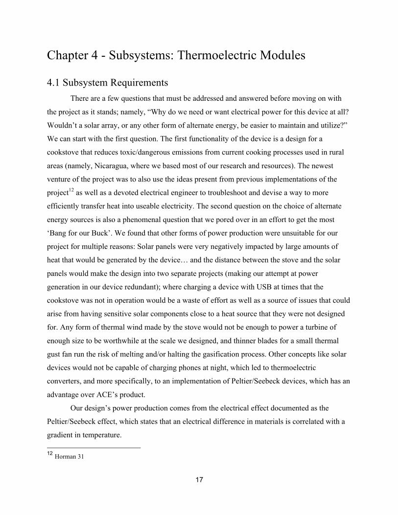
4.4 Design Drawings
Figure 4.1: Prototype On-Demand Charging System
The above design (Figure 4.1) takes inspiration from the previous team’s designs, as well
as the basics of solar charging circuits used commonly as camping circuits. The circuit takes
power from the power source (a simple array of TEGs in this case), and contains the power with
the group of linear loads in the circuit before it goes through a grounded regulator. The ‘trickle’
of current will grow as the temperature differential increases across the TEGs.
Future iterations of this include placing a killswitch between the diode and the power
source in case of an emergency as well as an LED at the output to indicate the device was ready
to charge a USB device safely.

22
Figure 4.2: Charging Design Prototype 2
One of the simple fixes to the power problem in the rural portions of developing nations
came as a shock to our initial assessment, mostly in the case of using car batteries as a common
charging method for cellular devices. One of the ways we discussed helping, in case the
community preferred to stick with their own way of charging phones was to configure the stove
to charge a car battery to be used in a similar fashion as how it is already being used in the area.
This design follows the general ‘trickle’ power charger system, and would require more
than one Peltier unit as described in previous problems. One of the other problems present in this
design has to do with charge time. Although the customer could charge a car battery in parts
while they use the device, in order to fully charge a car battery, the stove would have to be
running for far longer than it would take to cook dinner which is waste of fuel and detrimental to
the original purpose of the stove.

23
4.5 Final Project Design and Implementation:
Part 1
Figure 4.3: Finalized Charging Circuitry
Figure 4.8 attends to the needs of the USB device, and focuses exclusively upon this
function. It was decided upon review and testing that the multi-faceted approach we first
attempted in an effort to maintain one circuit was too convoluted and prone to issues on a mass
production scale. The first circuit deals with the USB power, and ignores the inputs for data as
there is no data being transmitted from an electrical power source. The 1.8V DC sources
symbolize individual TEG’s, which are added in series to gain the desired voltage for the Buck-
Boost converter to deliver to the USB (F) port.

24
Part 2
Figure 4.4: Finalized Fan Circuitry
The second circuit (as shown above) takes its full attention as the fan which
simultaneously cools the internal portion of the cookstove, but also stokes the gasification
process expanded upon in previous sections of the report. Whereas in the first circuit the
electrical power is regulated at five volts, we decided to let the voltage have a bit more free
reign. This was decided with the idea that the hotter the gasification process became, the greater
the difference in temperature would become, inducing a higher voltage which would allow the
system to cool down and drop voltage.
This cycle would continue to regulate the internal temperature in a way that would
require no outside interference, making a negative feedback loop which would keep the system
from reaching such a high temperature that the system would be too warm in all parts to function
as a charger (due to the lack of temperature differences which would halt the Seebeck effect from
occurring).

25
Chapter 5: Results
Figure 5.1: Prototype Cookstove Test
5.1 Results from Combustion Chamber Test Results for the combustion chamber were found through detailed testing of the product.
Thermocouples as well as an IR temperature probe were used to find temperatures of stove
surfaces over time. Stove temperatures were measured over time, and not just at steady state in
order to understand the time required for the stove to reach a stable temperature (steady state).
This time is needed, for it allowed calculation of time where a user can safely touch the outside
surface of the stove.

26
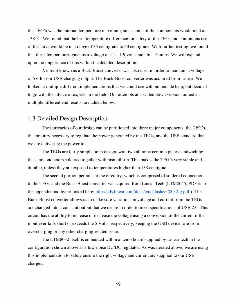
The temperature distribution for the outer surface of the combustion chamber was created
from data taken via both thermocouple and IR probe. The temperature distributions recorded, as
shown in Figure 5.2, showed some consistency with the expected values with the surface
temperature finite elements analysis calculation, however, these values were much lower than the
analysis showed, and was likely the result of improper initial conditions within the analysis. This
error is likely due to an incorrect assumption of combustion temperature in the FEA or incorrect
material emissivity data for the refractory cement in the FEA.
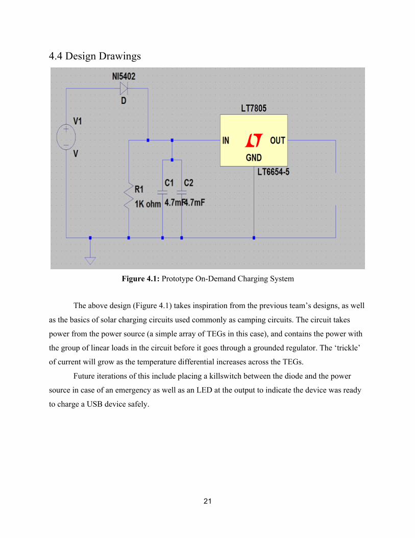
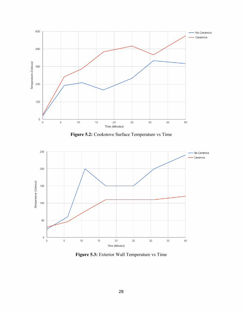
Tests were conducted both with and without a cement element inside the combustion
chamber in order to gauge various effects of its presence. The temperatures recorded showed that
the addition of a cement element in the prototype both decreased outer surface temperature and
increased overall temperature output at the top of the stove. These results show the beneficial
nature of the cement material’s inclusion. The refractory cement both increases the temperature
within the combustion chamber and serves to resist radiative heat transfer to the outer wall
surface.
The tests to confirm whether gasification was present were done visually. Ideally, testing
for molecules from the fire’s output and confirming whether products of synthetic gas
combustion are present can test for successful gasification.
The equipment necessary for this testing was not available to Team Forge, so an
alternative testing methodology was used. Since gasification results in a smokeless burn, the
main visual testing criteria would come from whether smoke could be seen during testing.
Another method for testing successful gasification involves visually inspecting the synthetic gas
output ports on our design to see if secondary combustion is occurring. Using both of these
testing methodologies it was confirmed that gasification was occurring during the testing
process. After an initial burn period the smoke in the fire dissipated and secondary combustion
was visible in the synthetic output ports; gasification was present.
In order to gauge the heat output from our stove in operation versus competition the heat
output during our test was measured by heating a fixed volume of water on our stove and
recording the time it took to boil. Knowing the specific heat of water, the latent heat of
vaporization of water, the amount of water used, and the time it took for the water to boil
allowed for the calculation of the heat transferred to the water. It was found through
thermodynamic calculations (Appendix D.) that the heat output of our stove under non-ideal

27
conditions (high winds limited the heat transfer from the flames to the cookware) was 4.91kW.
This heat output was consistent with our expectations and similar to competing products.
Table 5.1: Temperatures Recorded on Cookstove with/without Refractory Cement Insulator
(Red is without ceramics, Green is with. All Temps in Celsius)
No Fan (13 mph wind) 0 minutes 5-7
minutes 8-12
minutes 17-18
minutes 25-27
minutes 31-34
minutes 41-43
minutes
Combustion Chamber Base 24 NA NA NA NA NA NA
Combustion Chamber Top
(Inner diameter of top ring) 24 230 250 200 280 400 (115
outer) 380
Thermoelectrics/Fan 24 130 135 50 150 220 290
Exterior Wall 24 60 200 150 150 200 240
Cooking Surface (1 inch
above top) 24 430 430 150 600 NA
650 (620
3 inches
above)
No Fan (12 mph wind)
(constantly adding more
wood) 0 minutes 5-7
minutes 11-12
minutes 17-18
minutes 24-25
minutes 30-31
minutes 36-38
minutes
Combustion Chamber Base 30 380 590 550 N/A 500 720
Combustion Chamber Top
(Inner diameter of top ring) 30 290 345 460 500 440 570
Thermoelectrics/Fan 26 60 245 275 350 310 280
Exterior Wall 30 46 76 110 110 110 120
Cooking Surface (2 inches
above top) 30 N/A N/A N/A 180 (60
in pot) 300 (boiling
water) N/A
28
Figure 5.2: Cookstove Surface Temperature vs Time
Figure 5.3: Exterior Wall Temperature vs Time
29
5.2 Thermoelectric Test Results
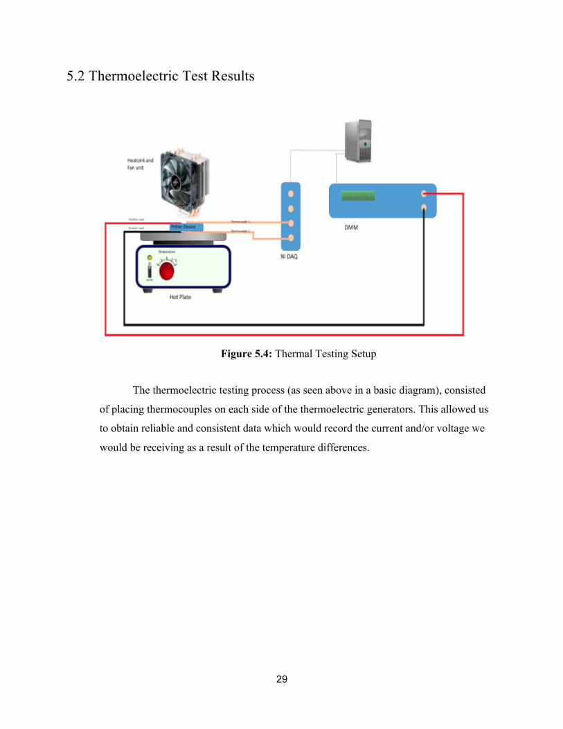
Figure 5.4: Thermal Testing Setup
The thermoelectric testing process (as seen above in a basic diagram), consisted
of placing thermocouples on each side of the thermoelectric generators. This allowed us
to obtain reliable and consistent data which would record the current and/or voltage we
would be receiving as a result of the temperature differences.

30
Figure 5.5: Thermal Testing Voltages from TEGs in Series Without Fan or Heat Sink on
Hotplate
The graph above (Figure 5.5) shows the voltage as a function of time without any form of
thermal dampening, where we are able to see that the TEGs follow a seemingly linear
progression in values as they are added in series after the first initial voltage spike. This means
that connecting two TEG’s in series creates a voltage greater than or equal to the voltage made
by two unconnected TEG’s under the same conditions.

31
Table 5.2: Temperatures and Voltage Recorded using Thermoelectric Generators
Thermoelectric Test 0 minutes
4-6 minutes
13-14 minutes
17-18 minutes
25-26 minutes
Combustion Temperature (Celsius) 27 550 664 410 640 Thermoelectrics/Fan Temperature (Celsius) 27 36 53 75 77 Voltage Output (Volts) 0 N/A 0.08 0.06 0.07
Unfortunately, our final tests that we conducted with the electrical systems and
thermoelectrics in place were unsuccessful. The cookstove again succeeded in gasifying the
material being burned and resulted with a clean burn, but the output of our thermoelectric
generators yielded near-negligible results. Due to the limited clearance within the electronic
housing section of the cookstove, the TEGs and fan apparatus were within close proximity of the
air intake at the bottom of the chamber, and thus most likely congested the cooling area. The fan
was not able to start due to the almost even temperatures within the TEG area, which resulted in
minimal voltage output and could not start the charging process. The predicted power output
(over an hour of cooking, with a steady 15 volt and .6 amp current power supply) was 9
Watt/hours, and we unfortunately did not reach this predicted output. For the future iteration of
the cookstove, the base volume will need to be increased to better incorporate the heat sink, fan,
and cooling plate for the thermoelectrics to better result in a wider temperature difference.
Contrary to the individual tests of the TEGs, they lacked proper airflow from the fan and were
not capable of cooling efficiently. Adding a battery to the circuit will allow the fan to
immediately begin cooling the TEGs, and would hopefully result with the predicted tests’
outcomes.

32
Chapter 6: Cost Analysis Table 6.1: Overall Prototype Cost
Part or Service Unit Price Quantity Total Expenditure
TEGs $1.93 12 $23.18
Circuit Board $8.25 2 $16.50
EE Wires/etc. $41.64 1 $41.64
CRS 1008 $102.091 0.5 $51.05
Computer Fan $15.00 1 $15.00
Manufacturing $700 1 $700
TOTAL –– –– $847.37
1Unit cost is based on price for 30 sq. ft. Sheet
As shown in Table 6.1 above, the prototype cost for the initial design was $105 based on
the parts alone, and a total of $805 including the manufacturing of the design from our
manufacturing company, PWP. For our project, it was determined that the manufacturing for our
design would drop significantly from $700 for a single prototype to $250 for a mass production
price. The value of $700 was significantly higher than originally thought due to the fact that the
parts given to the company were not keyed to location for the welding process, and required
most of a day to complete instead of around 40 minutes on average. This is a significant driver
on the price for our design since welding is a manual process and thus increases the cost of the
design by a large margin. Other similar designs in the region, like from Proleña, are priced
around $500, and are very limited in their function. When compared to the mass production cost
of our design, around $350, ours is much more affordable than similar devices. Unfortunately,
the cost that was desired, around $150, is still out of reach for our current design. Hopefully with
future iterations and optimizations, the cost of this device will drop enough to reach this
threshold.

33
Chapter 7: Business Plan
7.1 Executive Summary The Forge stove harnesses the heat of gasification to generate electricity, and it is
designed to serve the impoverished population of rural Nicaragua. By providing both electricity
and a source of clean cooking, the stove justifies its target price of $130. The business plan
begins with a trial phase, in which stoves will be shipped from the United States to Nicaragua
and sold in partnership with NGOs, such as Grupo Fenix. At the conclusion of this phase, stove
production will be scaled up or will give way to the use of frugal thermoelectric kits in their
place.
7.2 Introduction “Impoverished, alone in the dark.” This sentiment has likely been felt throughout areas of
rural Nicaragua, where, as of 2005, only 35% of the population has power13. Contrasted with the
90% of the population that has energy access in urban areas, this figure suggests the need for a
call to action: in one of the world’s poorest nations, a gap in resources and opportunity is still
perpetuated. With our product, The Forge, we can close this gap, empowering citizens of rural
villages with both the literal and proverbial power necessary for economic freedom. Our product
is a modular cooking surface that uses gasification in its heating process, which yields a clean
burn and high temperatures, which are then harnessed to also generate electricity. This electricity
can be used to power the unit itself, a cell phone, or even a car battery. It can also, however, be
used to start a microbusiness, and Forge users can gain economic empowerment by selling the
electricity to other members of their community. In addition, our product serves a dual purpose,
and by providing a cooking surface with clean emissions we meet an environmental imperative
as well. According to the United Nations Development Programme, Nicaragua has set targets for
90% of its citizens to have access to electricity and cut use of fossil fuels by 90%14 by 2020.
Thus, our product will fill a unique niche by providing an additional good to the Nicaraguan
government in addition to driving progress toward its electrification goal. By filling multiple
13 Grogan 253 14 UNDP
34
needs with a portable, affordable unit, Forge more than meets the demands of its potential users,
and, with success in Nicaragua, can be scaled to impact lives throughout the developing world.
7.3 Goals and Objectives Unlike a traditional business, Forge is not strictly motivated by profits and the traditional
bottom line. Instead, we choose to focus on a double bottom line, which incorporates a social
return on investment as well as a financial one. This does not make Forge a charity; while a
focus will be placed on achieving social good, the business will stand to be self-sufficient. In
other words, we intend to operate Forge at modest profit with massive potential for social gain.
With this in mind, a double-bottom line venture still must be held accountable to metrics and
process, and we choose to use a modified version of Robert Kaplan’s Balanced Scorecard to
measure our impact and effectiveness. Clark, et al.15 highlight the focus on outcomes of the
business process, and this strategy will serve Forge well. Integration of Forge technology into the
market is crucial, and tracking growth and customer feedback is integral to our success. In other
words, Forge will challenge itself to meet the needs of its customers and partners in addition to
investors.
To have success and deliver social impact, Forge will need to coordinate with partners to
help distribute the product, meet customer needs, and achieve long-term market penetration.
Working with the Nicaraguan government and non-government organizations (NGOs) will be
essential to both maintaining a low cost and reaching customers at the end of the supply chain.
Proleña and Grupo Fenix, two NGOs active in northern Nicaragua, both had conversations with
the Forge team, and their knowledge of the market and customer base already has contributed to
the Forge design. They also work to distribute, and in some cases, build the cookstove
technology employed in northern Nicaragua, and their help would be key to ensuring that the
Forge stove reaches customers and makes the desired social impact.
Last, our team hopes to execute a three-phase business plan, to introduce our product to
the market, to refine its tracking, and, eventually, translate to scaling. The first phase of the plan
will involve an initial trial, in which we leverage partnerships with Grupo Fenix, Proleña, or
another organization to deliver prototypes or the information on how to build the prototypes to
15 Clark, Long, Rosenzweig, and Olsen

35
customers in centralized villages. The second phase will constitute an evaluation of our strategy,
in which we decide whether to begin manufacturing units in Nicaragua, continue with the onsite
application of the technology, or exit. In our final phase, as Nicaragua adds infrastructure, we
will scale the technology to provide greater generation, while the cookstove can be used to reach
the extremes of our market base and serve last-mile customers.
7.4 Description of Product The Forge cookstove harnesses the gasification and Peltier/Seebeck effects to enable
efficient fuel combustion and reuse the excess heat generated from this burn to create electricity.
The generation of electricity from excess heat is achieved via TEGs, or thermoelectric
generators. These devices use the temperature differential between the stove casing and the
ambient air to produce electricity. The casing of the stove is composed of Cold Rolled Steel
(CRS) 1008, fourteen thermoelectric generators, a computer fan, and the circuitry necessary for
power output. The user inserts biomass into the top of stove and ignites it. The burning fuel is
then stoked by the fan, which causes gasification to occur. Simultaneously, the computer fan
cools the cold side of the TEGs, creating a large enough temperature difference for the TEGs to
generate electricity. Some of this electricity will be returned to the system to help power the
computer fan, while the remainder will be outputted to a USB device or car battery.
Ultimately, the value of this product lies in its versatility for its price. In Section 7.6, the
Forge stove is compared to units already used in the Nicaraguan marketplace. Neither the Grupo
Fenix solar cooker nor the Proleña Mega Ecofon generate electricity, and both are currently
priced higher than our target price 16. Our prototype, which is comparably priced when produced
at scale using current manufacturing methods, still maintains the advantage of electricity
generation. Paul and Uhomoibhi17 note that electricity generation also provides an economic
benefit, and microbusinesses such as mobile charging stations can flourish with access to reliable
electricity18. This further justifies the price of the cookstove, and for a low-income market base,
every dollar they spend must add value. The Forge stove also boasts a clean burn, reducing the
exposure of users to particulates that results from other methods of cooking. In essence, the
16 Thermelectric Generators Fan or Heat Sink on Hotplate. .32 Horman 12 17 Paul and Uhomoibhi 18 ICL 1104

36
Forge stove excels because it meets a wide assortment of its market’s needs in one, has a
moderate price tag, and the solutions currently employed in rural Nicaragua cannot do the same
for the same dollar amount.
7.5 Potential Markets As noted in the introduction, the target market for Forge is the rural, mountainous
northern part of Nicaragua. First and foremost, the market’s dire need for electrification made it
a clear choice for our product. As of 2012, only 77.9% of Nicaragua’s population has access to
electricity, placing the country in the bottom five in the Americas for total electrification19. This
percentage, however, is not representative of the rural, undeveloped North, where only 42.7% of
the population has access to electricity. Especially when compared to the same statistic in 2010
of 43.2%, this figure is alarming; not only is the problem severe, but change has stagnated, and
significant improvement has yet to be documented.
Forge’s lightweight, modular design makes it ideal for rural Nicaragua, allowing it to
mitigate one of the market’s major challenges: developing a supply chain. Both Proleña and
Grupo Fenix said the solution was to build their stoves on location. Grupo Fenix took a low-tech
approach, using reflective panels to create a cookstove that utilized sunlight, while Proleña
trained locals to build more advanced cookstoves alongside technicians. In both cases, their
products tended to be large and immobile, creating limitations on their use and where they could
be used. Research also supports their claims, and, in his paper Rural Nonfarm Incomes in
Nicaragua, Leonardo Corral states that only 43% of houses have access to a dirt road, and only
22% of these households can access electricity20. Thus, we believe that as a mobile solution,
Forge can alleviate the supply chain woes of Proleña and Grupo Fenix, and can provide an
alternative to large unit construction on site.
Finally, the Nicaraguan government’s commitment to electrification, particularly in the
renewable energy sector, is another market factor that falls in Forge’s favor. The government has
stated that it wants to reach full electrification by 2017, an ambitious effort that will require
significant investment in renewable energy sources21. In addition, the country has a soft
19 World Bank 20 Corral 429 21 BNEF

37
commitment to reach 74% renewable energy by 2018 and 91% renewable energy by 202722.
These goals suggest that the government is open to bringing in renewable energy, and this may
serve to be beneficial as Forge advances into later stages of its business model. The government
has already instituted subsidies for energy distributors at a rate of $.05-$.06 per kilowatt hour.
This service is provided to distributors using various renewable energy sources, including
biomass, and the subsidy goes to either providers who intend to install infrastructure or support
current generators. Currently, Forge falls in the later group, and if the thermoelectric generation
technology proves to be scalable as infrastructure improves, we can transition into generating
renewable energy large scale, while maintaining the current cookstove model for fringe
customers.
With all of this in mind, the market serves as an ideal environment to test the scalability
and use of the thermoelectric technology in the field. Grupo Fenix and Proleña each serve a base
of potential customers in our target market, and Proleña already employs a strategy that may
serve as a viable contingency plan for Forge. If circumstances make our target price of $130
unattainable, then we will begin by employing an onsite manufacturing plan similar to Proleña’s
strategy. Unlike the Mega Ecofon stove that they produce, however, the Forge technology is less
expensive, more mobile, and has the added benefit of electricity generation. Electrical
components would still need to be shipped to site, but their weight is insignificant relative to that
of a full cookstove. Were this implementation to succeed, then larger-scale local manufacturing
could take place, and the proof of concept could still lead into the eventual phase of scaled-
generation with the rise of infrastructure.
7.6 Competition Currently, Forge does not face direct competition in the northern Nicaraguan market. The
market is sparse, and this is not without reason. According to the World Bank, the adjusted net
income per capita per Nicaragua was about $1700 USD in 201423. This number, however, does
not reflect the vast divide between the wealthy and the poor within the nation. The World Food
Programme states that, as of 2010, 76% of the population survives on less than $2 USD per day,
a staggering level of poverty that does not support large, single-payment purchases. Thus, 22 Thermelectric Generators Fan or Heat Sink on Hotplate. .32Climatescope 23 World Bank

38
affordability is an issue, and any product brought to market must justify its price against
alternatives, including, in the case of a cookstove, electing to cook over an open fire. Another
difficulty is expanding a supply chain to Nicaragua’s mountainous North. Based on our
conversations with Grupo Fenix and Proleña, we discovered that a supply chain is difficult to
maintain. The lack of infrastructure outlined in the previous section is the reason behind this, and
shipping large cookstoves or quantities of materials is both expensive and a logistical challenge.
Non-modular solutions are often constructed in rural villages themselves, as manufacturing and
distributing a finished product is difficult and costly24.
While they may not necessarily produce energy, other cookstoves can compete with
Forge in price and in the primary function, green cooking. In Table 2.1, we see one of the
cookstoves Grupo Fenix uses to serve people in the region. Already the price of the stove stands
out; $300 is a high price for a cookstove, and this price sits well above our target price of $130.
In addition, this stove uses reflective panels to generate heat, and it reaches a cooking
temperature of 150⁰ C25. This temperature is not sufficient for many cooking needs, and, along
with the price and large size of the unit, we feel that the stove discussed can be improved upon,
and our solution and those of others can outperform this model.
Proleña, on the other hand, has a stove that better serves their audience. The Mega
Ecofon is priced at $203, making it a more affordable option than Grupo Fenix’s solar stove26
Similarly, however, it is not mobile; the stove is large, with a design, according to Horman,
“recommended for small businesses”27. This limitation gives the Forge stove an upper hand, and
its lightweight design allows it to be moved, perhaps allowing it to reach last mile customers
who lack the materials to construct a Mega Ecofon stove. The Mega Ecofon also does not
generate electricity, and, like the Grupo Fenix stove before it, it has a difficult time justifying its
price.
Although they do not serve the Nicaraguan market, African Clean Energy produces the
ACE 1, a cookstove that competes very well with the Forge Stove. With a price of $150, the
stove is affordable, and it uses a similar gasification process28. It also generates electricity;
24 Proleña 25 Grupo Fenix 26 Proleña 27 Horman 13 28 African Clean Energy

39
unlike the Forge stove, however, it uses solar energy instead of thermoelectric components to
generate its power. The stove also is lighter than the Forge model, and, at 4.6 kg, it is less than
half the weight of our team’s product. Currently, the ACE 1 is superior to our prototype in nearly
all facets, and it is the benchmark for our team’s design process. While we are confident that we
can price our stove below $150 in the future, we currently cannot, and we hope to emulate the
success that African Clean Energy has enjoyed.
7.7 Sales/Marketing Strategies To market the Forge stove effectively, we will need to prove to our customers that the
stove is both affordable and worth the substantial price. To do so, we will utilize a variety of
tactics already in use; in particular, we will use methods already in use by Proleña and Grupo
Fenix to take our product to market. Proleña allows customers to pay for stoves in installments,
as a collective, or by using their labor to build models onsite29. We will continue this method,
and in our first phase we will test the installation of the thermoelectric components on site as a
method to reduce the sticker price of our stove. In addition, Nicaragua currently has a thriving
microfinance market, with over $568 million in outstanding loans30. We hope to tap into this
network, and help our customers take small loans to pay for our product over time instead of as a
lump sump. Finally, we will recruit Proleña and Grupo Fenix volunteers to help to market our
product; they will advocate for the potential benefits of clean cooking and the possible
implications electricity can have on individual micro business, generating trust among our
customer base and further justifying to them the price of the cookstove.
In addition to serving rural villages, Forge also seeks to reach last mile customers. These
customers are outside the reach of traditional supply chains, and whether it be for logistical or
economic reasons, this problem is a challenge that Forge is willing to accept. As Corral stated
previously, a significant portion of households do not have access to dirt or paved roads, and this
could stymie any effort to ship a 10 kg stove to their location. Therefore, we will serve these
customers by delivering a kit of thermoelectric components instead, and providing a more frugal,
albeit less effective, solution to them. For payment, Forge intends to utilize a scheme similar to
the Grupo Fenix nano loan. This microfinancial tool allows families to take a small loan, which 29 Proleña 30 MixMarket

40
they can pay back by hosting technicians who assemble their stoves and educate customers about
the product31. Our team plans to use a system in this fashion to ensure that these customers can
afford our stove, regardless of their income level. The costs of this are built into our overhead,
and we feel that our service to these customers will contribute meaningfully to our social impact.
7.8 Manufacturing To manufacture Forge’s prototype cookstove, our team contacted PWP Manufacturing to
produce our initial model. The costs of this single stove were estimated to be $706.11, with labor
constituting the majority of the expenditure (PWP). The material used, Cold Rolled Steel (CRS)
1008, required intensive manual labor to be formed to fit our stove. Much of this cost, however,
can be distributed over multiple stoves. In our first phase of the model we will be prepared to
manufacture a 20 stove starting inventory, at the projected cost of $309.90 per stove. This will
not be sufficient as we scale, however, and upon the start of phase two, we will produce a cast of
our combustion chamber to reduce labor cost for use with injection molding. This will cost
thousands of dollars and is not economical for the team’s trial period, but, as Forge continues to
grow, we will have the capacity to scale our operation and invest in efficient production.
Last, our location of manufacturing will change over the course of our Forge’s lifetime.
For phase one of our business plan, we will begin by manufacturing our prototypes in the United
States and shipping them to Nicaragua. For this phase, we estimate our shipping costs for 20
units to total $1811.50, and we can accept this price for our trial phase. With scale, however, we
cannot maintain our target price along with these shipping cost, and moving manufacturing to
Nicaragua is our best solution for phase two and beyond. To start with manufacturing at this
phase, we believe $20,000 will be sufficient to begin our search, and, along with developing a
cast for our chamber, this should give us reasonable accommodations to begin our work. Our
inventory will increase on a yearly basis, and, from Table 7.3 and Table 7.4, you can see that our
overhead costs have risen to represent this increase.
31 Grupo Fenix

41
7.9 Product Cost and Price The production cost of our prototype is outlined in the table below:
Table 7.1: Prototype Cost by Part
Part Vendor Unit Price Quantity Total Expenditure
TEGs Vktech $1.93 12 $23.18
Circuitboard Mouser $8.25 2 $16.50
CRS 1008 MkMetal $102.091 0.5 $51.05
Computer Fan Fry's Electronics $15.00 1 $15.00
TOTAL –– –– –– $105.73
1Unit cost is based on price for 30 sq. ft. Sheet
These costs are representative of producing an individual unit, and do not include a bulk
discount. While hard numbers are not available for purchasing each component in bulk, we have
received estimates from vendors and industry experts on prices when our project achieves scale.
By purchasing steel by the ton in bulk quantities as opposed to in single sheets, we can purchase
steel at a rate of approximately $18 per unit, cutting costs by nearly 70%32. In addition, we can
purchase TEGs for about $1 each in bulk quantities, further lowering costs of our units. The team
believes that materials costs can be reduced by approximately 50% in bulk, giving us a target
materials price of $58 for the second phase of our plan.
Notably, labor costs are absent from the above table. PWP Manufacturing, the company
that manufactured our prototype, estimated a labor cost of over $500 for a single unit. They did,
however, state that a great deal of the costs stemmed from high fixed costs, and that, were
manufacturing scaled to 500 units, our contact estimated that costs would total $309 per unit,
with a considerable decrease if a more effective method of manufacturing were used instead of
manual fabrication and welding. Thus, the solution to our costing problem lies in reducing labor
costs. To do so, our team will turn to a less labor-intensive manufacturing process. The two
alternatives recommended by our manufacturer were powder metallurgy and casting the
combustion chamber into a mold. Both processes are similar in that they have large fixed costs 32 Alibaba

42
upfront that will translate to savings in the long run. Our teams believe that casting is the most
viable method at the moment, and we will begin with this approach in phase two of our business
plan. Our target price for labor at this point is $40/unit, and with casting, this is an attainable
goal.
In total, our projected materials and labor costs total to $98 for a single unit. Although
$130 is our target price for the product, this is not realistic to deliver to the end consumer.
Whether the stoves are produced in Nicaragua or in the United States, shipping costs will be
considerable, particularly in the case of last mile distribution. Until Forge can ascertain the
expense of shipping our stoves at the conclusion of phase one, our team intends to charge a price
closer to $150. This price is consistent with the standard set by African Clean Energy as seen in
section 7.7, and we believe that this price is both affordable to our customers and reasonable for
us to gauge shipping prices early on in our business’s development. As phase two comes about
and our costs become fully apparent, we can transition to a price closer to our $130 target,
reaching a broader user base and increasing Forge’s social impact. Finally, we will price the
thermoelectric kits at $50 in our phase one trial, and move to a price of $30 in phase two as
Forge scales.
7.10 Service or Warranties In determining an appropriate warranty for the Forge cookstove, we found that separating
the electrical system and the combustion chamber into two separate categories best allows us to
serve our customer base and maintain low costs. Vktech estimates their thermoelectric devices
have a lifetime of 200,000 operating hours, which is a time well beyond the expected lifetime of
our units33. This estimate does not, however, necessarily account for outdoor usage in a rural
environment, and we will provide a warranty lasting for the duration of each phase of our
business plan, at each phase electing to continue the warranty ourselves or to train Proleña
technicians to install the system and continue to distribute parts to them. Our team elected to take
this approach in order to ensure and maintain the trust of our customers as well as to guarantee
the ongoing use of our cookstove after a potential exit from the market.
33 Vktech

43
The combustion chamber, on the other hand, is difficult to effectively warranty. Due to
the high materials cost, high labor cost in the first phase of our plan, and our inability to repair
the metal frugally, Forge will not provide a warranty for stoves that become defective after use.
While the team intends to ensure that all stoves are in working order upon shipment, we cannot
affordably offer a warranty that extends beyond manufacturing defects. Thus, in order to uphold
customer trust, we can offer a discount on the thermoelectric kit in the event that the cookstove is
no longer operable.
7.11 Financial Plan and Funding To finance Forge, our team would employ a hybrid monetization model as a part of three
phase plan for our product. Our team has produced a phase one plan, and, depending on the
outcome of phase one, two phase two plans that will detail our progression. For phase 3, the team
believes that further investigation into the technology and cost projection is necessary, and this
area of the plan is certainly an area in which a future design team could expand upon the project.
That being said, our projection for Forge is that the project is viable through phase two, and that
investors will receive full return at the completion of the second phase.
In both plans that we have produced, phase one is identical; Forge will produce 20 stoves
and prepare 20 electrical kits to distribute to partner technicians. The stoves and kits will be
shipped to Nicaragua, and a Forge team member would accompany them to oversee their sales
and distribution. In each table below, you can see that we have projected a cost of about $10,000
for this phase. This includes the costs of manufacturing the stoves, the cost of assembling the
electrical kits, and the overhead of flying a team member to Nicaragua, paying for his lodging,
and overseeing the development of the project. Based on the price of our goods in this phase one
period, we expect revenue of $4000. This will leave us with $4000 of cash on hand, enough to
account for any potential setbacks that may result. We intend to fund this with a $10,000 grant or
angel investment; at this stage in our business plan, we do not intend to create profits, and this
proof of concept of our technology could be applied to other ventures as well. From here, we can
process feedback from our partners and customer segment, and move forward with the phase two
plan that best suits the situation. Version A involves moving stove manufacturing to Nicaragua
and moving forward with production there, while Version B involves moving forward with the
modular kits to continue the spread of technology through the country.

44
Table 7.2: Business Plan A
Phase 1 Phase 2
Forge - Business
Plan A FY1 FY2 FY3 FY4 FY5 FY6
Stoves Sold 20 40 100 200 500 1000
On-site Setups 20 15 40 60 100 150
Cost per Stove $309.90 $108.00 $108.00 $108.00 $108.00 $108.00
Cost per Setup 39.68 $20 $20 $20 $20 $20
Overhead $3,000 $20,000 $5,000 $5,000 $5,000 $5,000
Total Cost $9,991.60 $24,620.00 $16,600.00 $27,800.00 $61,000.00 $116,000.00
Price per Stove $150 $130 $130 $130 $130 $130
Price per Setup $50 $30 $30 $30 $30 $30
Revenue $4,000 $5,650 $14,200 $27,800 $68,000 $134,500
Grant Money $10,000 $0 $0 $0 $0 $0
Investment $0 $20,000 $0 $0 $0 $0
Annual Profit ($5,991.60) ($18,970.00) ($2,400.00) $0.00 $7,000.00 $18,500.00
Total Net Cash $4,008.40 $5,038.40 $2,638.40 $2,638.40 $9,638.40 $28,138.40
In-Field
Stoves/Setups 40 95 235 495 1095 2245
On the previous page, the first financial plan for Forge is detailed, outlining projected
costs and revenue through FY6 of our venture which we project to be 2023. Version A of the
plan accounts for the scenario in which our stove technology performs well, and is a success in
phase one. Here, we move into Nicaragua to begin production while preparing to bring
manufacturing to scale. We also will continue to support the kit for customers who cannot

45
receive a full stove due to logistical issues. This action is accounted for in overhead; the $20,000
is spent to acquire manufacturing space, produce a casting mold for our combustion chamber,
and to maintain any lodging costs for technicians in the field. To pay for this upfront, we will
seek a venture capital investment of $20,000 for a 40% stake in Forge. Unlike in the previous
round, we will apply for venture capital because we can expect a rapid return on investment. In
the first 5 years, we project a 125% return on investment, with growth vastly increasing in the
coming fiscal years. The table above stops in FY6, the first possible exit for investors at which
their investments can be recouped with a modest profit. They can, however, remain invested to
capture significant gains in coming years. At the conclusion of phase two of this plan, Forge will
have brought over 2000 stoves and setups into the field, creating both the social impact and
modest line that it originally sought out.
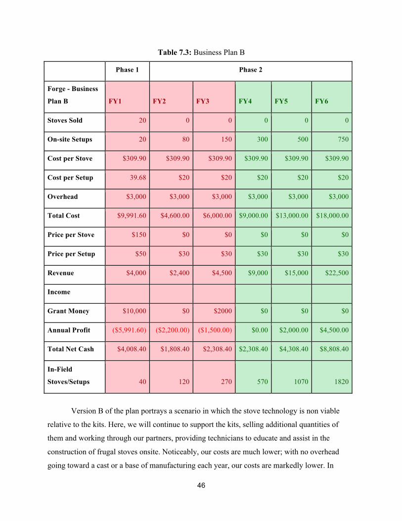
46
Table 7.3: Business Plan B
Phase 1 Phase 2
Forge - Business
Plan B FY1 FY2 FY3 FY4 FY5 FY6
Stoves Sold 20 0 0 0 0 0
On-site Setups 20 80 150 300 500 750
Cost per Stove $309.90 $309.90 $309.90 $309.90 $309.90 $309.90
Cost per Setup 39.68 $20 $20 $20 $20 $20
Overhead $3,000 $3,000 $3,000 $3,000 $3,000 $3,000
Total Cost $9,991.60 $4,600.00 $6,000.00 $9,000.00 $13,000.00 $18,000.00
Price per Stove $150 $0 $0 $0 $0 $0
Price per Setup $50 $30 $30 $30 $30 $30
Revenue $4,000 $2,400 $4,500 $9,000 $15,000 $22,500
Income
Grant Money $10,000 $0 $2000 $0 $0 $0
Annual Profit ($5,991.60) ($2,200.00) ($1,500.00) $0.00 $2,000.00 $4,500.00
Total Net Cash $4,008.40 $1,808.40 $2,308.40 $2,308.40 $4,308.40 $8,808.40
In-Field
Stoves/Setups 40 120 270 570 1070 1820
Version B of the plan portrays a scenario in which the stove technology is non viable
relative to the kits. Here, we will continue to support the kits, selling additional quantities of
them and working through our partners, providing technicians to educate and assist in the
construction of frugal stoves onsite. Noticeably, our costs are much lower; with no overhead
going toward a cast or a base of manufacturing each year, our costs are markedly lower. In

47
addition, our materials costs are significantly decreased in this model, ultimately meaning that
Forge would not have to turn to venture capital and sell shares of ownership. While Forge’s
profits are dramatically more modest in this scenario, the team would only need to seek a small
grant in FY3 to maintain a reasonable share of net cash on hand. This would ensure that Forge
could remain solvent if unexpected expenditures occurred, and allow the team to continue to
make a reasonable impact, selling 1820 units as opposed to 2245. This approach, however, is
notably less conducive to growth, and it may render the third phase ultimately unviable.
Phase 3 is the final stage of Forge’s mission, and, as implied above, this project is best suited to
occur after Version A of the business plan. Here, Forge will reinvest remaining profits to move
into large scale generation, using the thermoelectric technology to move to large scale
generation. We imagine our technology providing something of a “microgrid,” bringing
centralized power to region. While our engineers believe this scale is achievable and a
reasonable endgame for Forge, they have not produced a design to implement it in Nicaragua.
Thus, with additional time, our team hopes that future research can produce an actionable design
and plan for phase three, in which Forge can maximize impact, reap the aforementioned
subsidies described by Jacobs, et al.34, and continue into the future.
34 Jacobs
48
Chapter 8: Engineering Standards
8.1 Economic To generate the social impact that our team desires, the Forge stove needed to be
designed with the economic concerns of our customers in mind. The market we intend to serve is
one of the world’s poorest, and the product that we provide must justify every cent spent on it.
To make sure that Forge met this goal, we sought to use the most inexpensive materials suited
for rural Nicaragua, and our goal is to be able to provide a target price of $130. In addition to a
low price, we also added to the economic appeal of the stove by increasing its value through
additional functions. While the price of a stove is high compared to that of a solar panel, the
price of including circuitry in the stove is more comparable, and the stove itself can produce a
clean burn and generates electricity independent of conditions. Thus, by using inexpensive
materials and filling multiple niches in the market, our team has developed a solution that meets
the economic needs of the Nicaraguan people.
8.2 Environmental The largest positive environmental impact of Forge is its ability to produce a cleaner burn
of conventional fuels. A study was conducted in Florida aimed at determining the amount of air
pollution emitted from a proposed Gainesville Renewable Energy Center biomass plant.
Similarly, a power plant called ELCOGAS in Spain uses the gasification process to have a more
efficient burn as well as to minimize the pollutants emitted. Although both power plants use a
type of biomass as fuel, the amount of air pollution measured between the two showed that
ELCOGAS had lower emissions in all categories. The following chart shows the data recorded in
the two studies, as well as the percent increase of Gainesville Renewable Energy relative to
ELCOGAS.
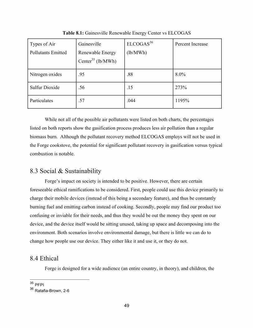
49
Table 8.1: Gainesville Renewable Energy Center vs ELCOGAS
Types of Air
Pollutants Emitted
Gainesville
Renewable Energy
Center35 (lb/MWh)
ELCOGAS36
(lb/MWh)
Percent Increase
Nitrogen oxides .95 .88 8.0%
Sulfur Dioxide .56 .15 273%
Particulates .57 .044 1195%
While not all of the possible air pollutants were listed on both charts, the percentages
listed on both reports show the gasification process produces less air pollution than a regular
biomass burn. Although the pollutant recovery method ELCOGAS employs will not be used in
the Forge cookstove, the potential for significant pollutant recovery in gasification versus typical
combustion is notable.
8.3 Social & Sustainability Forge’s impact on society is intended to be positive. However, there are certain
foreseeable ethical ramifications to be considered. First, people could use this device primarily to
charge their mobile devices (instead of this being a secondary feature), and thus be constantly
burning fuel and emitting carbon instead of cooking. Secondly, people may find our product too
confusing or inviable for their needs, and thus they would be out the money they spent on our
device, and the device itself would be sitting unused, taking up space and decomposing into the
environment. Both scenarios involve environmental damage, but there is little we can do to
change how people use our device. They either like it and use it, or they do not.
8.4 Ethical Forge is designed for a wide audience (an entire country, in theory), and children, the
35 PFPI 36 Ratafia-Brown, 2-6

50
sick, and the elderly all fall into it. A stove is an intrinsically understandable device, and Forge is
designed so that the only apparent difference between it and a regular cookstove is Forge’s
ability to generate electricity. Children who don’t yet understand the dangers of an open flame
should be supervised, as well as those who cannot completely control their motor movements.
These decisions ultimately rest upon the users to protect others around them and prevent
unwanted use. We will protect ourselves legally from unwanted and unreasonable liability, but
our design should be easily understood and safe enough to prevent most foreseeable issues.
8.5 Health & Safety Traditional cookstoves do not have any method of filtering or cleaning their emissions,
and thus the fumes emitted by a contained biomass-burning fire are innately hazardous to the
respiratory systems of those using them. Forge’s gasification effect attempts to remedy this by
reigniting gases that are normally released as pollutants for what is referred to as a “cleaner”
burn. There are still pollutants released by Forge, including carbon monoxide and dioxide, and so
it should only be used in a well ventilated environment. Furthermore, the physical weight of
Forge makes it so that it is heavy enough to not topple when loaded with fuel and cooking, but
light enough to move when unloaded and cool. This makes the cookstove safer than existing
portable cookstoves, but still convenient for the user.
8.6 Arts Table 8.2: SCU Core Arts & Humanities
Team Member Description Locations Matt Nelson Passive Cooling System Figure E-1 Matt Nelson Fan Cooling System Figure E-2 Matt Nelson Closed Loop Cooling System Figure E-3 Isaac Stratfold Stove Base Figure E-4 Austin Jacobs Casing Design #1 Figure E-5 Austin Jacobs Casing Design #2 Figure E-6 Austin Jacobs Thermoelectrics #1 Figure E-7 Austin Jacobs Thermoelectrics #2 Figure E-8 Jared Sheehy Split view of cook stove Figure E-9 Jared Sheehy Cooking Prongs Figure E-10 Jared Sheehy Handle Figure E-11
51
Chapter 9: Conclusion Team Forge designed and had a functional thermoelectric cookstove built and tested
within the timeframe that was previously established so as to complete it within the senior school
year. Our goals were to design, build, test, and analyze our cookstove such that it met the
requirements of our original ideas, and looking back on the accomplishments of our team, we
believe that we have created a successful product. Our baseline goals were to have a cookstove
reach boiling temperatures for water around the cooking surface and to have thermoelectric
generators convert the excess heat from the core chamber into electricity to charge a device using
a USB outlet. The voltage and current we needed to supply through the USB are 0.5 amps with 5
volts, and 9-12 volts for our fan which worked in conjunction with our heat sink.
Our secondary goal was to be able to have gasification occur in the device to be able to
supply a constant, clean burn while running the cookstove. This process essentially burns off all
tars and carcinogens produced through a standard burn process, and leaves the cookstove with a
smokeless burn. In order to produce the efficiency and heat transfer containment that we desired,
we looked into refractory ceramic plating for the inside of the combustion chamber. Through our
finite element analysis results, we found that the cookstove’s outer surface wall temperatures
would be around 400 ºC, which would be too hot for consumers to effectively go near when
cooking or else risk serious burns. When we conducted our first test with the device, without any
electronics or refractory elements to get a baseline of our temperature gradients, we found that
the highest output temperatures were only around 240 ºC and were thus significantly lower than
our computer analysis results predicted. We ran a second test with refractory cement instead of
ceramics to see what our profile would look like, and found that although the results were better
for the outer temperatures, and the benefit of having the cement permanently attached was
almost even with the drawback of its high weight and internal design.
Since we managed to get our design completely manufactured from PWP, our physical
product is perfectly designed to how we CAD modeled it. Regarding our electronics and
circuitry, we were given a buck-boost converter from Linear Technologies to be able to control
the output of the combustion chamber such that the electricity generated never exceeds the
maximum values needed for the USB device. One place that could see improvement with the
design is our outer aspects of the cookstove. We originally planned to have handles attached to
the side of the device to allow for easier transport, but since our device was manufactured

52
without handles, it proved exceedingly difficult if not impossible for us to assemble a set of
handles and attach them to the device without compromising the integrity of the device’s ability
to gasify. Some aspects in the next design that can be improved upon are its portability, which, in
its current state, is possible to carry since it is around 10 Kg, but having the availability of
handles would be much more successful. Finding an affordable solution for ceramic internal
tiling would also be a significant improvement to the design, since although the temperatures
generated were well under our estimates, they were still higher than we would have liked. Our
removable refractory cement was one option, but its weight was far too high to justify its use,
and we did not trust its integrity under the conditions we wanted it to function with, with the way
we developed it.
Something that we learned throughout the process of this design project was that we can
never truly trust simulated results for our project since although they give a good estimate of
what we are to expect, one incorrect input variable will lead to completely different results.
Setting up timelines and charts to keep us on track over the course of a few months was much
better for our team to work with than having a general idea of how we should proceed even if
some points seemed excessive. Aside from that, we discovered that it was very important to not
only get to know each other in the team, but how important it is to properly work with other
people over such an extended period of time. A final technical aspect that we learned was how to
manage and balance all the costs of the project, from purchasing the materials to getting our
designed manufactured, to buying devices for testing.

53
Bibliography "Air Pollution from Biomass Energy." PFPI (2011): n. pag. PFPI. Partnership for Policy
Integrity, Apr. 2011. Web. 6 June 2016.
Bergman, Theodore, Adrienne Lavine, Frank Incropera, and David Dewitt. Fundamentals of
Heat and Mass Transfer. 7th ed. Hoboken: John Wiley & Sons, 2011. Print.
Borgnakke, Claus, and Richard Sonntag. Fundamentals of Thermodynamics. Vol. 8/e. Hoboken:
John Wiley & Sons, 2013. Print
Chong, Lui. "Transparent Air Filter for High-efficiency PM2.5 Capture." Nature. Macmillan
Publishers, 16 Feb. 2015. Web. 2 Dec. 2015.
Clark, Catherine, David Long, William Rosenzweig, and Sara Olsen. "Double Bottom Line
Project Report: Assessing Social Impact in Double Bottom Line Ventures - CASE." CASE. N.p.,
n.d. Web. 24 May 2016.
"Coal Power: Air Pollution." Union of Concerned Scientists. N.p., n.d. Web. 22 Oct. 2015.
Corral, Leonardo, and Thomas Reardon. "Corral, L. and Reardon, T., 2001. Rural Nonfarm
Granatstein, D. L. "Gasification vs Combustion of Waste/Biomass" IEABioenergy. N.p., n.d.
Web. 22 Apr. 2016.
Grogan, Louise, and Asha Sadanand. "Rural Electrification and Employment in Poor Coutries:
Evidence from Nicaragua." World Development 43 (2013): 252-65. Www.elseviercom. Web.
Hebei I.T. (Shanghai) Co., Ltd. (n.d.): n. pag. TEC1-12706. Hebei I.T. (Shanghai) Co., Ltd. Web.
Horman, Christine, Matthew Lee, and Mark Wagner. Thermoelectric Cookstove. Santa Clara:
Dept of Mechanical Engineering, 2013. Print.
54
"Human Development Reports." |. N.p., n.d. Web. 24 May 2016.
Jacobs, David. "Analysis of Renewable Energy Incentives in the Latin America and Caribbean
Region: The Feed-in Tariff Case." Energy Policy 60 (n.d.): n. pag. Web.
Jaworski, C.M. "Observation of the Spin-Seebeck Effect in a Ferromagnetic Semiconductor."
Nature.com. Nature Publishing Group, 26 Sept. 2010. Web. 03 Dec. 2015.
Kinne, Susan. Communication with Grupo Fenix. Telephone interview. 23 Oct. 2015.
Lewis, Jessica J., and Subhrendu K. Pattanayak. "Who Adopts Improved Fuels and Cookstoves?
A Systematic Review." NCBI. National Center for Biotechnology Information, 1 Feb. 2012.
Web. 15 Oct. 2015.
Mal, R.; Prasad, R.; Vijay, V.K., "Design and testing of thermoelectric generator embedded
clean forced draft biomass cookstove," in Environment and Electrical Engineering (EEEIC),
2015 IEEE 15th International Conference on , vol., no., pp.95-100, 10-13 June 2015
Martino, Tom. Communication with PWP Quote. E-mail interview. 6 May 2016.
Narong, Sangwaranatee. "The Study of Cook-Stove Thermoelectric Generator Power." Advanced
Materials Research 979 (2014): 421-25.Applied Science and Technology [EBSCO]. Web.
"Nano Loans." Grupo Fenix. N.p., n.d. Web. 24 May 2016.
Nelson, William. "Climatescope 2013." Climatescope. Bloomberg New Energy Finance, n.d.
Web.
"Nicaragua Market Profile." Mixmarket.org. N.p., n.d. Web. 24 May 2016.
55
Paul, Damasen Ikwaba, and James Onohuome Uhomoibhi. "Generating Solar Electricity by
Solar Concentrators for Web-based Learning in Rural Areas in Tanzania: Issues of Practice and
Impacts." IEEE Xplore. N.p., n.d. Web. 24 May 2016.
"Polyacrylonitrile (PAN)" Encyclopedia Britannica. Britannica Academic. Encyclopedia
Britannica Inc., 2015 Web Dec. 3.
Ratafia-Brown, Jay. "Major Enviromental Aspects of Gasiciation-Based Power Generation
Technologies." U.S. DOE/NETL (2002): n. pag. Netl. Dec. 2002. Web. 6 June 2016.
Walker, Judith. Communication with African Clean Energy Interview. Telephone interview.
Nov. 2015.
Wolf, Lucas. Communication with Prolena Interview. Telephone interview. 16 Nov. 2015.
"Wood Stoves, Fireplaces, Pellet Stoves, and Masonry Heaters." Wood Stoves, Fireplaces, Pellet
Stoves, and Masonry Heaters. Washington State Department of Ecology, 2015. Web. 03 Dec.
2015.
"World Development Indicators| World DataBank." World Development Indicators| World
DataBank. N.p., n.d. Web. 24 May 2016.

A-1
APPENDIX A: Team Management Challenges, both blocking and non-critical, must be dealt with swiftly as they arise during
the design and construction of our device. When they become apparent, obstacles to the
completion of the project must be dealt with by priority, which will be determined by how
detrimental they are to the whole process. We will often have to decide as a group what to do
when certain challenges arise, even if they affect only one aspect of our final product (an issue
with an electrical component, for example). Everyone on the team will be tasked with
overcoming the challenge, unless the challenge requires a specific specialty that certain members
do not have. Ultimately, it’s the responsibility of the entire team to overcome challenges.
The process of completing our project falls into three distinct phases, ideally one for each
quarter. The first is the design phase, in which we completed a full outline of what our device
does, how it works, how it looks, and what it is made of. In order to to this, research was
completed about the background of the design. This included basics of thermodynamics, seebeck
effect, voltage and current needed to charge a phone, fuel emissions (including gasification), and
thermal conduction. This phase also included applying for grant money for research and
development. Numerous grants were reached out too, and Team Forge graciously got funding
from Santa Clara’s School of Engineering. This phase included research for a possible market as
well. Nicaragua became the ideal choice because they were the target market of the Team
Matador and also have numerous developing areas (off the power grid) that could use the
cookstove. Finally, the first phase consisted of routine documents in understanding producing
this conceptual design report, and finishing any other necessary documents. These documents
helped keep Team Forge on the same page. It also helped supervisors be aware of the progress
on the project.
The second stage is the fabrication stage. This includes the purchase of any materials and
the construction of all the individual parts of our product. Materials needed to be purchased
include sheet metal for housing, thermoelectric converters, wires and fans for cooling the wires,
thermal insulators, and testing equipment. More details about the materials being purchased are
in the budget (Table 4). This stage also includes the creation of prototypes and iterations. The
project was constructed in conjunction with PWP Manufacturing. This stage concluded with a
solid prototype and flowed into the next stage.

A-2
The final stage is the assembly stage, which included the final presentation of our thesis
and product. Several tests were conducted in this stage in order to understand problems from the
initial prototype. This stage included the completion of the final product after several tests and
alterations. The final product was presented as well as our completed thesis paper.

B-1
APPENDIX B: PDS Table B.1: Product Design Specifications
Requirement Reason Unit Value/Range
Performance
Output Voltage USB output specification
Volt (V) 5.00 ± .25 V
Output Current USB charging specification
Amp (A) 1.0-3.0 A
Input Temperature Material/ Thermoelectric Properties
Celsius (C) 260-595 C
Material Properties
Scrap Metal/Chimney Pipe
Combustion Chamber
N/A Sheet metal, .778 𝑚 ,
Various Requirements
Mobile Device Housing Required
LiPo Batteries Can be flammable / explosive in high heat
N/A Plastic/metal housing set away from heat source
Cost Constraint Customers will have very limited income
United States Dollars (USD)
<120 USD per unit
Ergonomics Ease of operation essential for uneducated consumers
N/A Simple product design-put above a heat source.
Quality / Reliability Embedded circuitry halts output if outside of specification
Volt, Amp,Celsius (Performance Specifications)
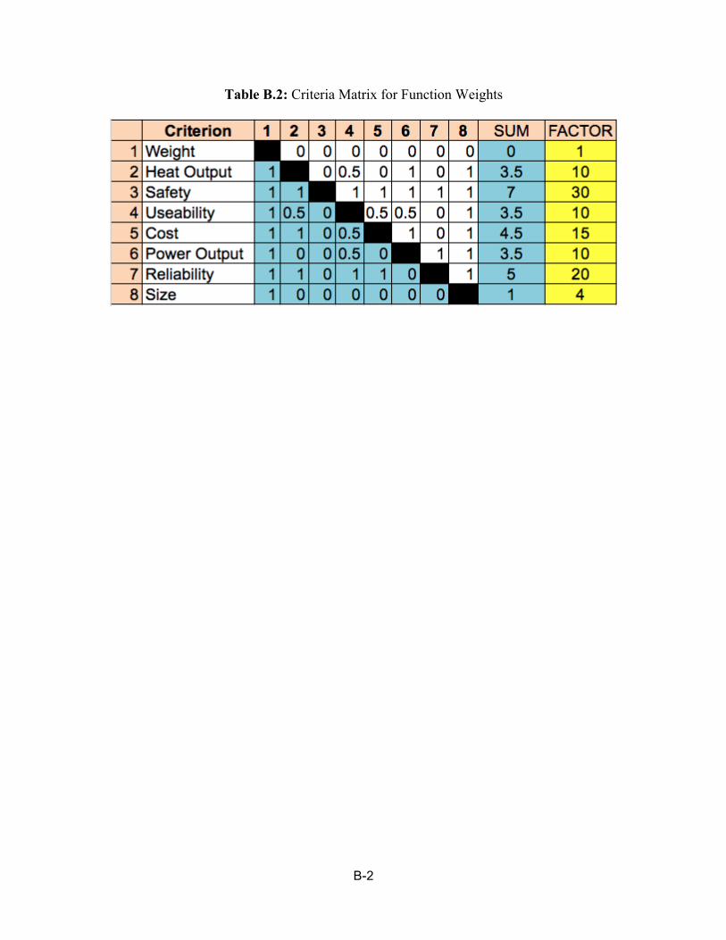
B-2
Table B.2: Criteria Matrix for Function Weights

C-1
APPENDIX C: Budget and Timeline Table C.1: Time Table for Prototype Completion
Table C.2: Team Forge Expendatures

D-1
APPENDIX D: FEA Diagrams and Calculations
Figure D.1: Detailed Calculations for Heat Dissipation Part 1

D-2
Figure D.2: Detailed Calculations for Heat Dissipation Part 2
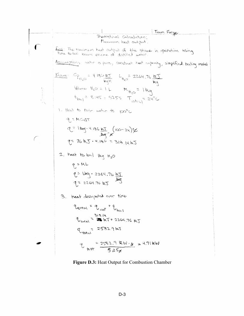
D-3
Figure D.3: Heat Output for Combustion Chamber
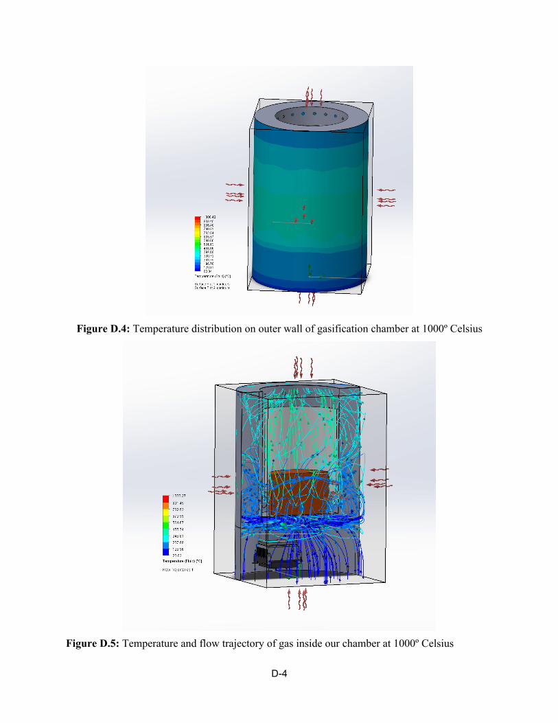
D-4
Figure D.4: Temperature distribution on outer wall of gasification chamber at 1000º Celsius
Figure D.5: Temperature and flow trajectory of gas inside our chamber at 1000º Celsius

D-5
Figure D.6: Temperature distribution on outer wall of gasification chamber at 800º Celsius
Figure D.7: Temperature and flow trajectory of gas inside our chamber at 800º Celsius

D-6
Figure D.8: Temperature distribution on outer wall of gasification chamber at 750º Celsius
Figure D.9: Temperature and flow trajectory of gas inside our chamber at 750º Celsius

D-7
Figure D.10: Temperature distribution on outer wall of gasification chamber at 600º Celsius
Figure D.11: Temperature and flow trajectory of gas inside our chamber at 600º Celsius

E-1
APPENDIX E: Detailed Diagrams
Figure E.1: Nelson Attributed Drawing 1
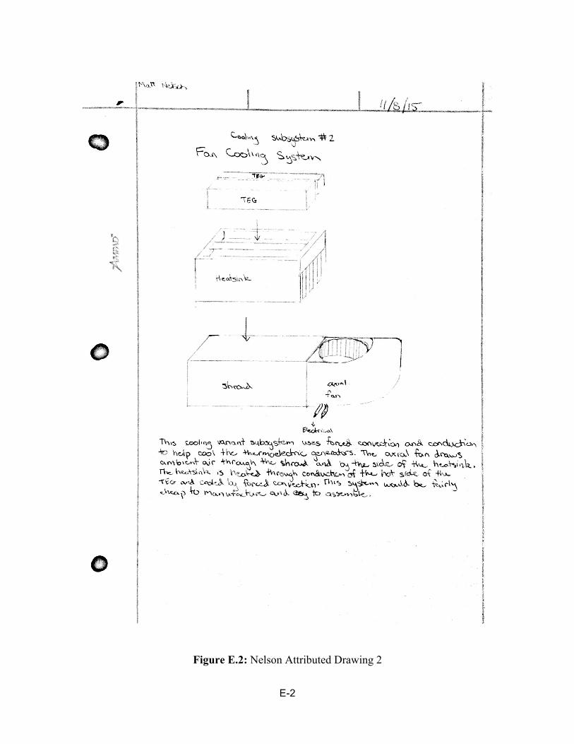
E-2
Figure E.2: Nelson Attributed Drawing 2

E-3
Figure E.3: Nelson Attributed Drawing 3
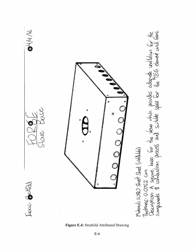
E-4
Figure E.4: Stratfold Attributed Drawing

E-5
Figure E.5: Jacobs Attributed Drawing 1
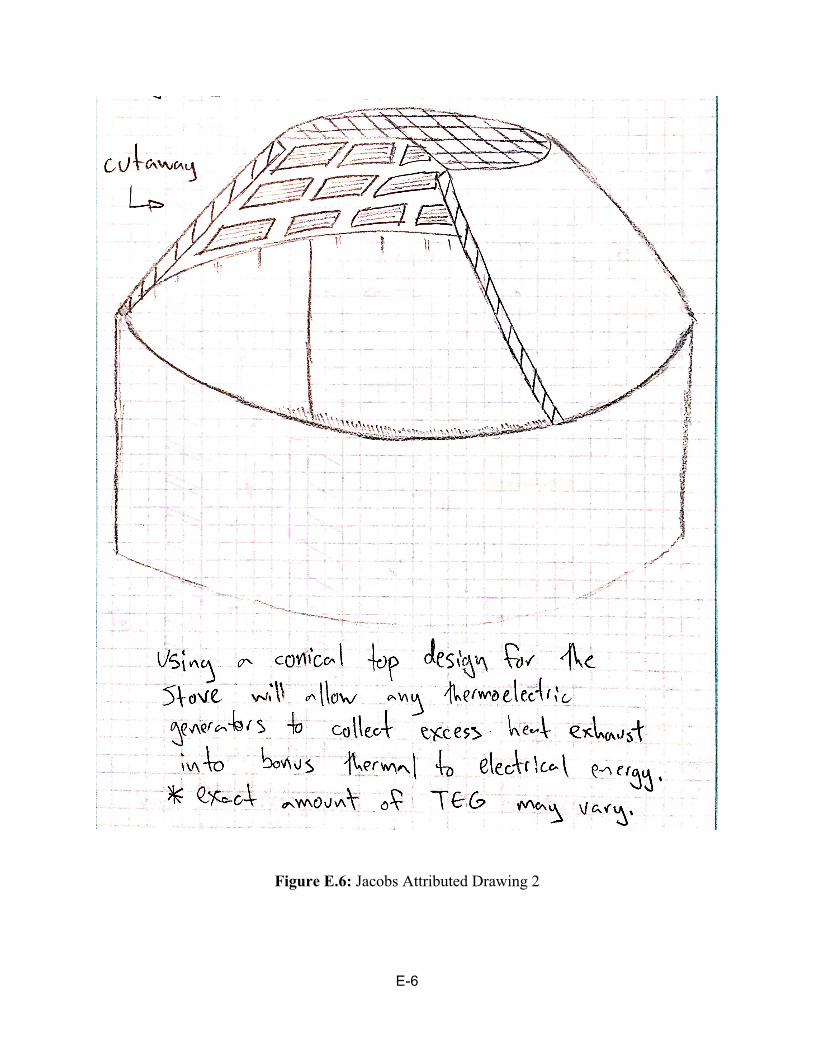
E-6
Figure E.6: Jacobs Attributed Drawing 2

E-7
Figure E.7: Jacobs Attributed Drawing 3

E-8
Figure E.8: Jacobs Attributed Drawing 4

E-9
Figure E.9: Sheehy Attributed Drawing 1

E-10
Figure E.10: Sheehy Attributed Drawing 2

E-11
Figure E.11: Sheehy Attributed Drawing 3

E-12
Figure E.12: Assembly Drawing
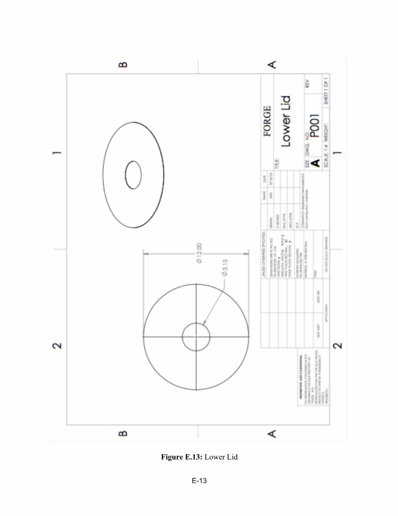
E-13
Figure E.13: Lower Lid
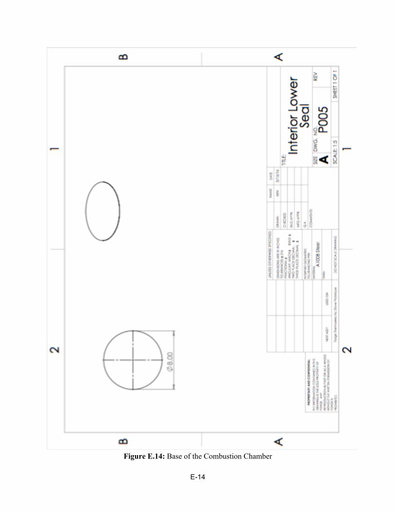
E-14
Figure E.14: Base of the Combustion Chamber

E-15
Figure E.15: Upper Lid

E-16
Figure E.16: TEG Holding Apparatus

F-1
APPENDIX F: Conference Presentation
Figure F.1: Senior Design Presentation Slides

F-2
Figure F.1 cont.: Senior Design Presentation Slides
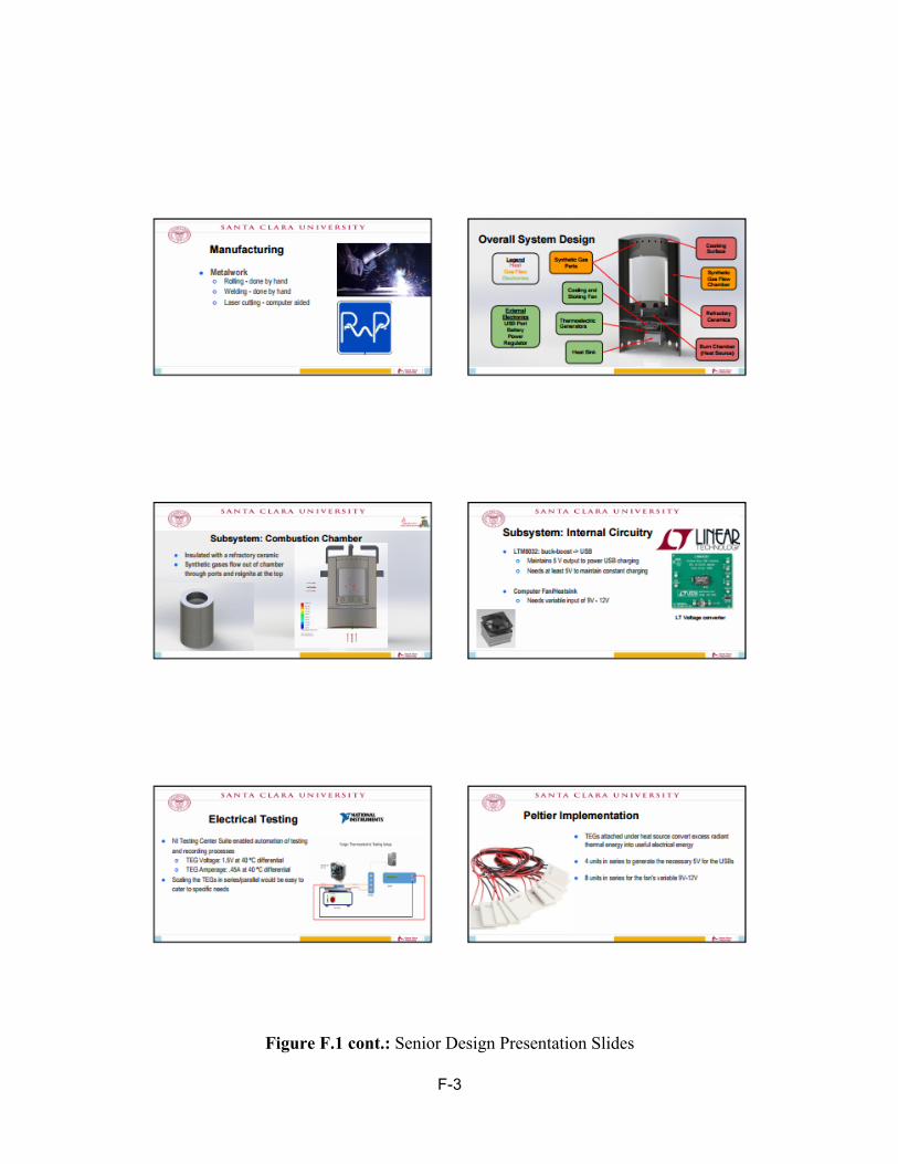
F-3
Figure F.1 cont.: Senior Design Presentation Slides

F-4
Figure F.1 cont.: Senior Design Presentation Slides

F-5
Figure F.1 cont.: Senior Design Presentation Slides

G-1
APPENDIX G: PWP Test Report
Figure G.1: 1008 Cold Rolled Steel Test Report