Embed Size (px)
Citation preview
International Journal of Science and Research (IJSR) ISSN: 2319-7064
ResearchGate Impact Factor (2018): 0.28 | SJIF (2019): 7.583
Volume 9 Issue 8, August 2020
www.ijsr.net Licensed Under Creative Commons Attribution CC BY
Fluid Flow Analysis in a Concentric Annulus with a
Rotating Inner Cylinder using ANSYS
M.R. Sahin
1Department of Mechanical Engineering, NERIST, Nirjuli, Arunachal Pradesh, India
Abstract: In the present study, CFD (Computational Fluid Dynamics) analysis of velocity and pressure fields that occur in annular
gap between two concentric cylinders was done. It encompassed the effects of inner cylinder rotation and fluid viscosity on an axial flow
structure. Fluid flow in concentric annuli with and without rotating inner cylinder was investigated by numerical simulation as similar
flows occur in drilling operations of oil wells. So, prediction of flow in drilling pipe in an annular space between wellbore and drill pipe
is essential to determine the variation in fluid pressure within the wellbore. Numerical results obtained for pressure drop and velocity
profiles from the present study were compared with experimental data as well as simulated data from the literature using two non-
Newtonian fluids (0.2 % Xanthan Gum and 0.2 % Carboxymethyl cellulose). The simulated results of pressure drop in present study
showed a good agreement with the experimental data and also yield data that were found rather more inclined towards the simulated
data. The velocity and tangential profiles also showed a good agreement with simulated velocity profiles reported in literature. The
additional work also contained, the study of Newtonian fluid (water) and its effects on hydrodynamics of these annular systems and
compared.
Keywords: Newtonian, Non-Newtonian, Concentric, Annulus, Rotation
1. Introduction
The flow in enclosed space have received much attention
because of many practical technology-driven applications
such as in production of oil & gas, centrifugally-driven
separation processes, electrochemical cells, fluid
viscometers and chemical reactors.
The petroleum industry in particular has shown considerable
interest in studies of fluid dynamics in annular space of oil
drilling operations. A typical example is the case of annular
flow of mud between drill shaft and drilling well casing to
remove cuttings and friction generated heat after drilling
operation. The cut region is cleaned to avoid unnecessary
rise in torque due to accumulation of particles [1]. The flow
of drilling fluid is highly affected by these drag particles
which is determined by velocity profiles in annular region
[2]. Therefore, for efficient drilling operations, knowledge
based on drilling fluid hydraulics is necessary. Moreover, the
rotating inner drill pipe promotes swirling fluid motion that
is superimposed on pressure driven axial flow in bore well
which is maintained axially downstream. In practical field,
pipe rotation drastically decreases frictional pressure loss
inside the wellbores [3]. So, these inner pipe rotations too
have a significant influence on drilling fluid hydraulics and
performance. Moreover drilling muds shows Non-Newtonian
behavior which is complicated to describe in a simple model.
So, proper selection of rheological model is necessary for
calculations to describe drilling fluid rheology.
An experimental study was done on combined axial and
rotational flow in annulus section of rotating inner wall (Fig.
1) [4].They mainly identified the following basic flow
regimes in the annular gap: laminar flow, laminar flow with
vortices, turbulent flow, and turbulent flow with vortices.
The works on flow velocity characteristics of rotating and
non-rotating Newtonian fluids in concentric and eccentric
annuli stands out among experimental studies on turbulent
flow [5]. These authors used Newtonian and Non-Newtonian
fluids to analyze turbulent flow in vertical annular sections
and to determine mean velocity profiles, their fluctuations
and cross-correlation by means of LDV technique (Laser
Doppler Velocimetry).
An extended study on their earlier experimental studies [5]
was done on vertical turbulent flows including the rotational
effects of inner tube [6]. Further, studies on an eccentric
annulus was done and was found that the influence of inner
cylinder rotation is more significant in the range of Reynolds
number (Re < 3000). However, this influence is found to be
lower in turbulent flows.
Figure 1: Schematic representation of different regions of flow
in annulus [4]
Experimental study of Newtonian and pseudoplastic fluid
flow was performed under the influence of central body
rotation by using LDA (Laser Doppler Anemometry) as the
measuring technique [7]. They used glucose syrup solutions
as Newtonian fluid and Carboxymethyl-cellulose (CMC)
solutions as non-Newtonian fluid to plot velocity profiles for
different flow situations and also highlighted the behavior of
the friction factor as a function of fluid flow rate.
Evaluation was done on the flow of pseudoplastic fluids in
eccentric annulus through numerical simulations using finite
difference technique [8]. The effects of inner cylinder
rotation on laminar flow of both Newtonian and Non-
Paper ID: SR20729013358 DOI: 10.21275/SR20729013358 1

International Journal of Science and Research (IJSR) ISSN: 2319-7064
ResearchGate Impact Factor (2018): 0.28 | SJIF (2019): 7.583
Volume 9 Issue 8, August 2020
www.ijsr.net Licensed Under Creative Commons Attribution CC BY
Newtonian fluids were studied in an eccentric annular
section to compare experimental and numerical results and
also to highlight velocity profiles with those reported by
other authors ([5], [1]) [9].
With rapid improvement of computational resources,
numerical simulation using CFD technique has become very
popular in several fields of Engineering, [10-16] helping to
shed light on the fluid dynamic behavior of annular flows.
The effects of porosity were incorporated at the boundary of
the system into their simulations [17]. They analyzed the
flow to predict pressure loss behavior of drilling fluids which
they later reported with information available in literature,
but did not compare their numerical results with
experimental data. Further, estimation on concentric annular
flows in vertical and horizontal arrangements based on CFD
simulations was done but without the effects of internal shaft
rotation [18]. The above mentioned research are mostly been
focused on experimental and numerical investigations
without comparisons. There is need for studies that combine
both experimental work and CFD simulations to investigate
pressure gradients of different Non- Newtonian fluids in
concentric annuli, evaluating their effects on the
hydrodynamics of these systems. Therefore, this piece of
work was taken by the present author during the Master
degree program (2015-17) at the Institute NERIST (North
Eastern Regional Institute of Engineering and Technology),
Arunachal Pradesh for evaluation and validations.
In the present work, CFD simulations were performed to
evaluate the pressure gradients and flow characteristics in
concentric annuli, with or without inner shaft rotation. The
velocity profiles and pressure drop is analyzed and validated
with standard results reported [19] in annuli with radii ratio
0.45 using two Non-Newtonian fluids involving 0.2%
Xanthan gum and 0.2% Carboxymethyl-cellulose aqueous
solution. In oil and gas drilling operations, the radii ratios of
conventional drilling are supposed to be in range of 0.3-0.5.
Hence radii ratio of 0.45 is selected as they may show the
best flow characteristics of the conventional wellbore
drillings. In addition to the above, the work is extended to
test the Newtonian fluid (i.e., water) to study the pressure
drop and flow characteristics and compared to the results
obtained for aforesaid two Non-Newtonian fluids.
2. Governing equations and Boundary
Conditions
A schematic view of the geometrical configuration is shown
in Fig. 2. The annular region is composed of two cylindrical
bodies with inner cylinder radius (R1=16mm) and outer
cylinder radius (R2=33.5mm). The axial length of cylinder is
z= 1.5m having radii ratio 0.45, to evaluate the effect of
rotating and non-rotating inner cylinders of two Non-
Newtonian fluids on their pressure drop, CFD simulations
were done. Velocity and constant pressure boundary
conditions of the fluid were imposed on the inlet and outlet of
the annulus. No-slip boundary conditions were used at the
inner and outer cylinders. The rotational speed of the inner
cylinder was 0 and 300rpm. An axial velocity of 0.69 m/s
was applied at inlet of the cylinder. The analysis was carried
out in laminar regime. The fluid velocity and pressure drop
for an annulus was calculated for Non-Newtonian fluids to
evaluate their effects on hydrodynamic of annular systems.
Drilling mud shows Non-Newtonian behavior which is
complicated to describe in a simple model. So, proper
selection of rheological model is necessary for calculations to
describe drilling fluid rheology. The rheological data of Non-
Newtonian fluids were best fitted by power law model which
can be expressed as
τ= k (γ) n Eq. (1)
Figure 2: Concentric cylinders with inner shaft rotation
The rheological data of aqueous suspensions of 0.2%
Xanthan Gum (XG) and 0.2% Carboxymethyl-cellulose
(CMC) were measured using a Brookfield rheometer at a
temperature of 25℃ [20], where K is consistency factor, n is
the power law index and τ is shear rate. The power law
parameters have been shown in Table 1 which was obtained
by regression for both fluids using a range of shear rate (γ)
varying from 0 to 80 s-1
to determine the parameters.
Table 1: Parameters of the power law model for the two
fluids Non-Newtonian fluids Parameters of the power law fluid
K[Pa.sn ] n[-] R2
0.2% XG solution 0.678 0.27 0.95
0.2% CMC solution 0.096 0.75 0.94
For an incompressible isothermal laminar fluid flow whose
effective viscosity depends only on strain rate tensor, the
modeling of flow can be defined by continuity equation (Eq.
(2)), using axial, radial and tangential components of the
momentum equation (Eq. (3), (4) and (5)) in cylindrical
coordinates [21].
Eq.(2)
Eq. (3)
Eq. (4)
Paper ID: SR20729013358 DOI: 10.21275/SR20729013358 2
International Journal of Science and Research (IJSR) ISSN: 2319-7064
ResearchGate Impact Factor (2018): 0.28 | SJIF (2019): 7.583
Volume 9 Issue 8, August 2020
www.ijsr.net Licensed Under Creative Commons Attribution CC BY
Eq. (5)
Considering the power law rheological model (Eq. 1)), we
used the effective viscosity (μE) concept to replace the
dynamic viscosity (μ) in these equations. The parameters of
this model (Table 1) were inserted in FLUENT 15 software.
3. Numerical Simulation
The procedure for the numerical simulation was
implemented using ANSYS FLUENT 15. Finite volume
numerical scheme in FLUENT were employed for solving
mathematical model. In FLUENT, the standard SIMPLE and
SIMPLEC (SIMPLE Consistent) algorithm are available in
solution methods. Simple is the default but SimpleC is more
beneficial for relatively less complicated problems. Here, the
simulations were performed in steady state regime, with
convergence criteria of 1e-4
and SIMPLE algorithm was used
for coupling pressure-velocity. PRESTO scheme was used
for pressure discretization and the scheme QUICK for the
discretization of equations of motion. The boundary
conditions adopted were an axial velocity of 0.69 m/s at
entrance and rotational speeds of 0 and 300 rpm in
concentric channel of inner cylinder.
3.1 Grid Independence Study
Grid construction was also done in ANSYS Fluent software.
In construction of grid, the cells adjacent to the walls of the
inner and outer tubes, as well as in the regions of entry and
exit were refined by mapped face meshing with a cells
growth factor of 1.1. A grid independence test was
performed in which the initial grid elements of 15520 were
considered and subsequently the values were raised to
154400 and 192000 respectively. The final mesh of 192000
cells was chosen as it gave a grid-independent solution.
Figures 3 and 4 showed the refinement of grid along the
annular section and in the entry
region of concentric annuli respectively.
Figure 3: Grid refinement Figure 4: Grid refinement
along concentric annular in intake region section
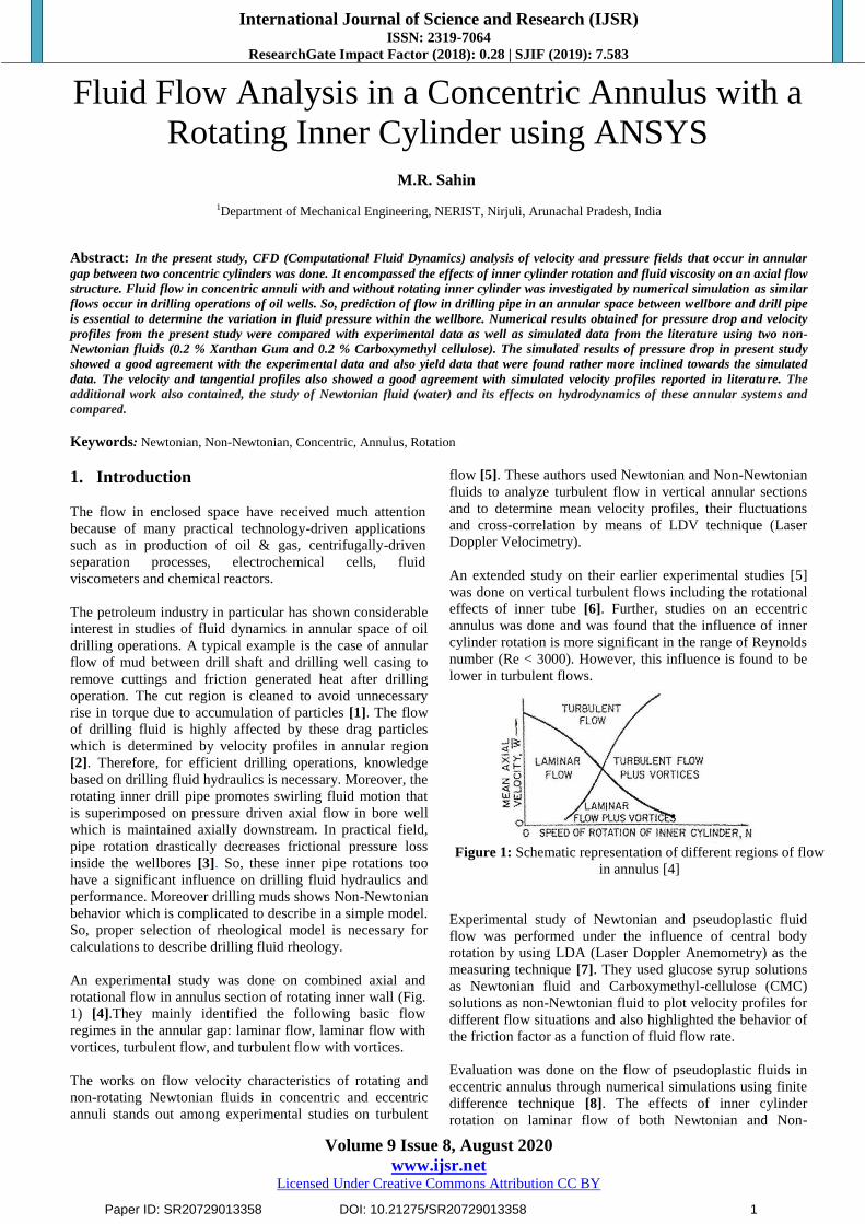
4. Results and Discussions
4.1 Effects of inner cylinder rotation on pressure drop of
Non- Newtonian fluids
In order to validate the present work, numerical studies were
simulated and the results obtained were compared with the
existing results of those studies. The results obtained from
the simulation for pressure drop in non-Newtonian fluids XG
and CMC are shown in Table 2 and Fig.5. The results were
also compared to both simulated and experimental data
reported in the literature [19]. The difference in data might
be due to following of grid construction with maximum
refinement in ANSYS FLUENT. The results obtained in the
Fluent were taken and plotted in software OriginPro 8.
In the present study, % reduction in pressure drop due to
change in rotational speed of simulated values were found
4.0 & 1.16 against the Non-Newtonian fluids XG and CMC
respectively. But the simulated values for the same Non-
Newtonian fluids were calculated as 4.1 & 1.2 respectively
which were already recorded in literature [19]. However, the
former values found from present study were more nearer to
the experimental and simulated values and seemed to be
more precise and acceptable than reported earlier by
previous workers. So the results from present study showed
that on increase in pipe rotation for same inlet velocity led
to decrease in pressure drop as listed in Table 2.
Figure 5: Comparison of Experimental pressure drop,
simulated and present work simulated values in concentric
annulus: (a) 0.2% XG (b) 0.2% CMC
Paper ID: SR20729013358 DOI: 10.21275/SR20729013358 3

International Journal of Science and Research (IJSR) ISSN: 2319-7064
ResearchGate Impact Factor (2018): 0.28 | SJIF (2019): 7.583
Volume 9 Issue 8, August 2020
www.ijsr.net Licensed Under Creative Commons Attribution CC BY
Table 2: Pressure drop for XG and CMC obtained from present study compared with those reported in literature
Particulars Rotational
Speed(rpm)
Published
Present work
Simulated
% reduction in
pressure drop due to
change in rotational
speed of present
simulated values
Experimental
% reduction in pressure
drop due to change in
rotational speed of
experimental values
Simulated
% reduction in pressure
drop due to change in
rotational speed of
simulated values
0.2% XG
solution
0 865 3.87
933 4.1
923 4.0
300 831.5 894 886
0.2% CMC
solution
0 1337 1.12
1648 1.2
1639 1.16
300 1322 1628 1620
4.2 Effect of inner cylinder rotation on flow
characteristics of Non- Newtonian fluids
In this section, the numerical results of fluid flow
characteristics for two Non-Newtonian fluids (0.2% XG and
0.2% CMC) with and without inner cylinder rotation cases
were reported. Velocity vectors and contour along with
pressure contour at different rotational speed (0rpm and
300rpm) were presented. Practically, the flow of drilling
fluid is highly affected by drag particles accumulated after
drilling which is determined by velocity profiles in annular
region [2]. So, it becomes necessary to determine velocity
profiles in annular region for efficient drilling operations.
In Fig.6 (a) the maximum velocity of XG was located at the
centerline in the annulus of concentric cylinders without
inner shaft rotation and it showed a non-parabolic profile.
This happened due to pseudoplastic nature of this fluid
having power index n=0.27. Fig. 6 (b) indicated velocity
contours that showed maximum velocity was located at
centerline in annulus of concentric cylinder without inner
shaft rotation. Again in Fig. 7 (a) the velocity increased
towards the inner part of the gap as the inner cylinder rotated
at 300 rpm and Fig. 7 (b) showed the corresponding velocity
contour that indicated that maximum velocity increased near
inner shaft due to rotational speed.
Figure 6: (a) Velocity vector of XG without inner shaft
rotation
Figure 6: (b) Velocity contour for XG (0rpm)
Figure 7: (a) Velocity vector of XG with inner shaft rotation
at 300 rpm
Figure 7: (b) Velocity contour for XG (300rpm)
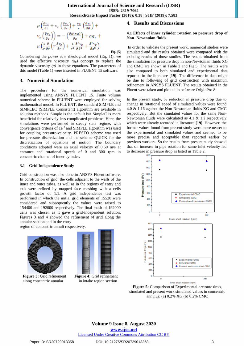
The pressure decreased at outlet of the cylinders in Fig. 8 (a)
whereas in Fig. 8 (b) with shaft rotation, the pressure
decreased more rapidly at the outlet.
Paper ID: SR20729013358 DOI: 10.21275/SR20729013358 4
International Journal of Science and Research (IJSR) ISSN: 2319-7064
ResearchGate Impact Factor (2018): 0.28 | SJIF (2019): 7.583
Volume 9 Issue 8, August 2020
www.ijsr.net Licensed Under Creative Commons Attribution CC BY
Figure 8: (a) Pressure contour of XG without inner shaft
rotation
Figure 8: (b) Pressure contour of XG with inner shaft
rotation at 300 rpm
In Fig 9 (a) the maximum velocity was located at centreline
of annulus. It showed almost parabolic profile as CMC has
power law index, n=0.75, which was closer to Newtonian
fluid (n=1). Velocity contour for CMC in concentric
cylinder without inner shaft rotation was shown in Fig. 9 (b).
Again in Fig. 10 (a) and 10 (b), the velocity vector and
contour indicated that the maximum velocity increased
towards the inner part as the cylinder rotated at 300 rpm.
Figure 9: (a) Velocity vector of CMC (0rpm)
Figure 9: (b) Velocity contour of CMC (0rpm)
Figure 10: (a) Velocity vector of CMC with shaft rotation at
300 rpm
Figure 10: (b) Velocity contour of CMC (300 rpm)
In Fig.11 (a) the pressure decreased at outlet of the cylinders
and whereas Fig 11 (b) indicated that with shaft rotation, the
pressure decreased more rapidly at the outlet.
Figure 11: (a) Pressure contour of CMC without inner
shaft rotation
Figure 11: (b) Pressure contour of CMC with inner shaft
rotation at 300 rpm
4.3 Effect of inner cylinder rotation on Axial and
Tangential Velocities of Non- Newtonian fluids
In this section, the numerical results of axial and tangential
velocities for two Non-Newtonian fluids (0.2% XG and 0.2%
CMC) with and without inner cylinder rotation cases were
reported and compared. The simulated profiles of axial and
tangential velocities were presented and compared with the
profiles of [19].
Paper ID: SR20729013358 DOI: 10.21275/SR20729013358 5

International Journal of Science and Research (IJSR) ISSN: 2319-7064
ResearchGate Impact Factor (2018): 0.28 | SJIF (2019): 7.583
Volume 9 Issue 8, August 2020
www.ijsr.net Licensed Under Creative Commons Attribution CC BY
In Figure 12 (b) profiles of axial velocities were almost
similar to simulated profiles reported in the literature for
both the fluids in Figure 12 (a). Distances were normalized
by radial distance r1 to S from outer to inner cylinder and
velocity was normalized by bulk velocity Ub (0.69m/s).
Significant differences could be seen in profiles normalized
axial velocities and it was noted due to the rheological
characters of the fluids.
The 0.2% CMC solution presented a parabolic profile as it
has a behavior index (n=0.75) very close to Newtonian fluid
(n=1).But, 0.2% XG solution having low behavior index
(n=0.27) displays a flattened profile. It was also seen that the
effect of rotation of inner shaft (300 rpm) did not influence
the axial velocity profiles as shown in the Figure 12.
0.0 0.1 0.2 0.3 0.4 0.5 0.6 0.7 0.8 0.9 1.0
0.0
0.2
0.4
0.6
0.8
1.0
1.2
1.4
1.6
u/U
b
r1/S
0.2% XG (0rpm)
0.2% XG (300 rpm)
0.2% CMC (0 rpm)
0.2% CMC (300 rpm)
Figure 12: (a) Simulated profiles of axial velocity
reported in literature.
0.0 0.1 0.2 0.3 0.4 0.5 0.6 0.7 0.8 0.9 1.0
0.0
0.2
0.4
0.6
0.8
1.0
1.2
1.4
1.6
u/U
b
r1/S
0.2% XG (0rpm)
0.2% XG (300rpm)
0.2% CMC (0rpm)
0.2% CMC (300rpm)
Figure 12: (b) Simulated profiles of axial of present work
Fig.12. Validation of axial velocity profiles normalised by
bulk velocity (Ub ) for fluids (0.2% XG and 0.2 % CMC)
in concentric annulus
In Figure 13, present study showed almost same tangential
velocity profiles as simulated values reported in literature
[19]. In 0.2% XG solution, the tangential velocity decreased
sharply as fluid moved away from the inner cylinder as its
non-Newtonian behavior was more evident. In contrast
against 0.2% CMC, tangential velocity decreased gradually.
Figure 13: Validation of simulated and present work
tangential velocity profiles normalised by bulk velocity (Ub)
for fluids (0.2% XG and 0.2 % CMC) in concentric annulus.
4.4 Effects of Inner cylinder rotation on pressure drop of
Newtonian fluid
In this section, for further validation, the work was extended
for studying flow characteristics in concentric annuli using
Newtonian fluid. Water was taken here as Newtonian fluid
for analysis. Considering same parameters and boundary
conditions, the results obtained after simulation were
analyzed below and were compared to the results obtained
for the two non-Newtonian fluids (XG and CMC) as shown
in Table 3.
It was noted that the pressure drop for water reduced slightly
to the tune of 2.9% (Fig.14), which might be due to
introduction of inner cylinder rotation (300rpm). By
comparison, it was found that pressure drop varied with
different fluids flowing through the annulus of rotating
cylinders. This was due to differences in behavior of fluids
having power index varying from n=0.27 to n=1 (Table 1).
Table 3: Comparisons of pressure drop for 0.2% XG, 0.2%
CMC and water due to change in rotational speed
Rotational speed (RPM) Particulars
0.2% XG 0.2% CMC Water
0 923 1639 1710
300 886 1620 1660
% reduction in pressure drop 4.0 1.16 2.9
Figure 14: Comparison of pressure drop for both Newtonian
and Non-Newtonian fluids
Paper ID: SR20729013358 DOI: 10.21275/SR20729013358 6

International Journal of Science and Research (IJSR) ISSN: 2319-7064
ResearchGate Impact Factor (2018): 0.28 | SJIF (2019): 7.583
Volume 9 Issue 8, August 2020
www.ijsr.net Licensed Under Creative Commons Attribution CC BY
In this section, the numerical results of fluid flow
characteristics for Newtonian fluid (Water) with and without
inner cylinder rotation cases were reported. The velocity
vectors, velocity contour and pressure contour for water were
presented here.
In Fig. 15 the maximum velocity without shaft rotation was
located at centerline of annulus in concentric cylinders. The
profile is parabolic in nature as water has power law index
n=1.
The velocity contour as well was shown in Fig. 16. But with
shaft rotation at 300 rpm, the maximum velocity occurred
near the inner rotating cylinder as shown in Fig. 17 and Fig.
18 respectively.
Figure 15: Velocity vectors without inner shaft rotation
(Water)
Figure 16: Velocity contour of Water (0rpm)
Figure 17: Velocity vectors with inner shaft rotation at
300 rpm (Water)
Figure 18: Velocity contour of Water (300 rpm)
In, Fig. 19 (a) the pressure decreased at outlet of the
cylinders but Fig 19 (b) indicated that with shaft rotation, the
pressure decreased more rapidly at the outlet.
Figure 19: (a) Pressure contour of Water (0rpm)
Figure 19: (b) Pressure contour of Water (300rpm)
4.6 Effects of inner cylinder rotation on axial and
tangential velocities of Newtonian fluid
In this section, the numerical results of axial and tangential
velocities for Newtonian fluid (Water) with and without
inner cylinder rotation cases were reported. The simulated
profiles of axial and tangential velocities were presented and
compared with the two Non-Newtonian fluids (0.2% XG and
0.2% CMC).
In Figure 20, it was seen that water gives a parabolic velocity
profile as its power law index is n=1 as compared to XG
having a flat profile (n=0.27) and CMC with almost
parabolic profile (n=0.75).
Paper ID: SR20729013358 DOI: 10.21275/SR20729013358 7

International Journal of Science and Research (IJSR) ISSN: 2319-7064
ResearchGate Impact Factor (2018): 0.28 | SJIF (2019): 7.583
Volume 9 Issue 8, August 2020
www.ijsr.net Licensed Under Creative Commons Attribution CC BY
Moreover, increment in shaft rotation (300rpm) practically
did not interfere in the axial velocity profiles. The
differences in profiles of three fluids were due to its
rheological characteristics.
0.0 0.1 0.2 0.3 0.4 0.5 0.6 0.7 0.8 0.9 1.0
0.0
0.2
0.4
0.6
0.8
1.0
1.2
1.4
1.6
u/U
b
r1/S
0.2% XG(0rpm)
0.2% XG(300rpm)
0.2% CMC(0rpm)
0.2% CMC(300rpm)
Water (0rpm)
Water (300rpm)
Figure 20: Comparison of axial velocities for both
Newtonian and non-Newtonian fluids
In Figure 21, the tangential velocity of water decreased
gradually but there was sharp decrease in tangential velocity
against Non-Newtonian fluids particularly XG. From
comparison with the non-Newtonian fluids, it could be noted
that the velocity gradient of the Newtonian fluid was greater
than that of Non-Newtonian fluid.
0.0 0.1 0.2 0.3 0.4 0.5 0.6 0.7 0.8 0.9 1.0
0.0
0.1
0.2
0.3
0.4
0.5
0.6
0.7
0.8
w/U
b
r1/S
0.2% XG (300 rpm)
0.2% CMC (300rpm)
Water (300 rpm)
Figure 21: Comparison of tangential velocity both
Newtonian and Non-Newtonian fluids
5. Conclusion
The present study revealed the following outcomes of the
investigation:
1) The simulated results of present study of the two fluids
showed a decrease in pressure drop with inner cylinder
rotation in the concentric annulus. The pressure drop after
comparison showed nearest values to experimental values
as well better results than simulated values reported in
literature [19]. Hence, it was inferred that the
computation for pressure drop was almost accurate and
validated using ANSYS Fluent 15.
2) The present simulated results showed that the axial
velocities in the concentric annulus were flat for XG
solution and parabolic for CMC solution. But, the
influences of inner shaft rotation on the profiles were
negligible. Again, the tangential velocity profiles
showed a sudden decrease in tangential velocity of XG
solution as it moved away from the inner cylinder, while
this decrease was more gradual with the CMC solution.
The velocities after comparison showed similar profiles
to simulated velocities collected from the literature.
Hence, it was in good conformity with the previous work
cited in literature.
3) To accumulate more information and precise data, the
current study was extended to Newtonian fluid and
compared with the two non-Newtonian fluids. The study
revealed that the pressure drop for water reduced slightly
(reduction of 2.9%) due to introduction of inner cylinder
rotation (300rpm). After comparison, it was computed
that pressure drop varied with different fluids flowing
through the annulus of rotating cylinders. This was due to
differences in behavior of fluids all having power index
varying from n=0.27 to n=1. The property of Newtonian
Fluid (n=1) was substantiated in the present investigation.
4) For axial velocities water gave a parabolic velocity
profile as its power law index is n=1 as compared to XG
having a flat profile (n=0.27) and CMC with almost
parabolic profile (n=0.75). Moreover, increment in shaft
rotation (300rpm) practically did not interfere in the axial
velocity profiles. The differences in profiles of three
fluids were found due to their variable rheological
characteristics.
5) The tangential velocity for water decreased gradually but
there was sharp decrease in tangential velocity against
Non-Newtonian fluids particularly XG. From comparison
with the Non-Newtonian fluids, it was found that the
velocity gradient of the Newtonian fluid was greater than
that of Non-Newtonian fluid.
Finally, it was inferred that the results obtained from present
study were more nearer to the values obtained by the
previous workers and hence more reliable. The extended
work also helped in differencing the rheological
characteristics of various fluids which has effects on
hydrodynamics of annular systems.
References
[1] Nouri, J. M. and J.H. Whitelaw (1997). Flow of
Newtonian and non-Newtonian fluids in an eccentric
annulus with the rotation of the inner cylinder. Int. J.
Heat and Fluid Flow, 18, 236-246.
[2] Escudier, M.P., I.W., Gouldson, P.J. Oliveira and F.T.
Pinho (2000). “Effects of inner cylinder rotation on
laminar flow of a Newtonian fluid through an
eccentric annulus”. Int. J. Heat Fluid Flow,21, 92-103.
[3] Duan, M., S. Mishka, M. Yu, N.E. Takach, R.M.
Ahmed and J.H. Hallman (2010). Experimental study
and modeling of cutting transport using foam with drill
pipe rotation. SPE Drilling & completion, 25(3), 352-
362.
[4] Kaye, J. and E.O.,Elgar (1958). "Modes of Adiabatic
and Diabatic Fluid Flow in an Annulus with an Inner
Rotating Cylinder, Trans. Asme, 80, 753-765.
[5] Nouri, J. M., H. Umur and J. H. Whitelaw (1993).
“Flow of Newtonian and non-Newtonian fluids in
concentric and eccentric annuli”. J. Fluid. Mech.,
253,617- 641.
Paper ID: SR20729013358 DOI: 10.21275/SR20729013358 8

International Journal of Science and Research (IJSR) ISSN: 2319-7064
ResearchGate Impact Factor (2018): 0.28 | SJIF (2019): 7.583
Volume 9 Issue 8, August 2020
www.ijsr.net Licensed Under Creative Commons Attribution CC BY
[6] Nouri, J.M. and J. H. Whitelaw, (1994). “Flow of
Newtonian and non-Newtonian fluids in a concentric
annulus with rotation of the inner cylinder”, J. Fluid.
Eng., 116, 821-827.
[7] Escudier, M. P. and I. W. Gouldson, (1995). Concentric
annular flow with center body rotation of a Newtonian
and a shear-thinning liquid. Int. J. Heat Fluid Flow, 16,
156-162.
[8] Fang, P., R. M. Manglik and M. A. Jog (1999).
Characteristics of laminar viscous shear-thinning fluid
flows in eccentric annular channels. J. Non-Newtonian
Fluid Mech., 84, 1-17.
[9] Escudier, M.P., P.J. Oliveira, F.T. Pinho (2002). Fully
developed laminar flow of purely viscous non-
Newtonian liquids thrpugh annuli, including effects of
eccentricity and inner cylinder rotation. Int. J. Heat
Fluid Flow, 23, 52-73.
[10] Vieira Neto, J.L., A. L. Martins, C.H. Ataide and
M.A.S. Barrozo (2014). The effects of inner cylinder
rotation on the fluid dynamics of Non-rotating
Newtonian fluids in concentric and eccentric annuli,
Braz. J. Chem. Eng.,31(4), 829 – 883.
[11] Vieira Neto, J.L., C.R. Duarte, V.V. Murata, M.A.S.
Barrozo (2008). Effect of a draft tube on the fluid
dynamics of a spouted bed: Experimental and CFD
studies. Drying Technol., 26, 299-307.
[12] Cunha, F. G., K. G. Santos, C. H. Ataíde, N. Epstein
and M. A. S. Barrozo (2009). Annatto powder
production in a spouted bed: An experimental and CFD
study. Ind. Eng. Chem. Res., 48, 976-982.
[13] Barrozo, M. A. S., C. R. Duarte, N. Epstein, J. R. Grace
and C. J. Lim (2010).Experimental and computational
fluid dynamics study of dense-phase, transition region
and dilute-phase spouting. Ind. Eng. Chem., 49, 5102-
5109.
[14] Santos, K. G., V. V. Murata and M. A. S. Barrozo
(2009). Three-dimensional computational fluid
dynamics modeling of spouted bed. Can. J. Chem.
Eng., 87, 211-219.
[15] Oliveira, D. C., C. A. K. Almeida, L. G. M. Vieira, J. J.
R. Damasceno and M. A. S. Barrozo (2009). Influence
of geometric dimensions on the performance of a
filtering hydrocyclone: An experimental and CFD
study. Braz. J. Chem. Eng., 26(3), 575-582.
[16] Pereira, F. A. R., M. A. S. Barrozo and C. H. Ataíde,
(2007).CFD predictions of drilling fluid velocity and
pressure profiles in laminar helical flow. Braz. J.
Chem. Eng., 24, 587-595.
[17] Fisher, K. A., R. J. Wakeman, T. W. Chiu and O. F. J.
Meuric (2000). Numerical modeling of cake formation
and fluid loss from non-Newtonian muds during
drilling using eccentric/concentric drill strings with/
without rotation. Chem. Eng. Res. Des., 78, 707714.
[18] Ali, W. A. (2002).Parametric study of cutting transport
in vertical and horizontal well using computational
fluid dynamics (CFD). M. Sc. Thesis, Department of
Petroleum and Natural Gas Engineering, West Virginia
University, United States.
[19] Vieira Neto, J.L., A. L. Martins, C.H. Ataide and
M.A.S. Barrozo (2014). The effects of inner cylinder
rotation on the fluid dynamics of Non-rotating
Newtonian fluids in concentric and eccentric annuli,
Braz. J. Chem. Eng.,31(4), 829 – 883.
[20] Ataíde, C. H., F. A. R. Pereira and M. A. S. Barrozo
(1999). Wall effects on the terminal velocity of
spherical particles in Newtonian and non-Newtonian
fluids. Braz. J. Chem. Eng., 16, 387-394.
[21] Bird, R. B., W. E. Stewart and E. N. Lightfoot
(2002).Transport Phenomena. Second Edition, John
Wiley & Sons Inc., New York.
Author Profile
Mehtaj Ridwana Sahin is currently working in
Jorhat Polytechnic as Lecturer in Mechanical
(Automobile Deptt.), Jorhat. Assam. She did her
Master's degree in Mechanical Engineering with area
of specialization in Thermo-Fluid from NERIST, Nirjuli, Arunachal
Pradesh in 2017, graduated from Dibrugarh University, Dibrugarh,
Assam in 2014.
Paper ID: SR20729013358 DOI: 10.21275/SR20729013358 9


![Transient Natural Convection in an Annulus with Thermal ... · with mixed boundary conditions. In [5], natural convection in a narrow horizontal cylindrical annulus for fluid of Pr](https://img.pdfslide.us/doc/110x75/5ed62f2904e9cb4adb670c7f/transient-natural-convection-in-an-annulus-with-thermal-with-mixed-boundary.jpg)