Embed Size (px)
Citation preview

Journal of Engineering Sciences, Assiut University, Vol. 34, No. 5, pp. 1507-1523, Sept. 2006
FLANGE COMPACTNESS EFFECTS ON THE BEHAVIOR OF STEEL BEAMS WITH CORRUGATED WEBS
_____________________________________________________________________
Mohamed Dabon, Professor
Department of Civil Engineering, University of Tanta, Egypt
A. S. Elamary, Lecturer
Department of Civil Engineering, University of Al-Azhar, Qena, Egypt
(Received August 8, 2006 Accepted September 23, 2006)
ABSTRACT– In this paper, the effects of the flange compactness on the
behavior of steel beams with corrugated webs are experimentally and
analytically studied. The experimental program consists of four simply
supported beams with different web configurations (Flat or Corrugated)
and different flange compactness (non-compact or compact). Nonlinear
finite element technique was used to model the tested specimens and to
carry out the parametric study. The variables of the parametric study
were the thickness and the width of the flange transversal stiffeners (FTS),
and the flange thickness (FT). The results obtained from the finite element
were compared with the corresponding experimental ones that show a
reasonable degree of accuracy. Finally, comparison between beams with
corrugated webs and those with flat webs was carried to exhibit the
advantages and disadvantages of using web corrugation. The results
indicate that; the flange transversal stiffeners enhances the beam yield
load by 21% and the flange thickness can increase the yield load by 56%,
where if both of them are used (FTS and FT) the beam yield load can
achieved 72% more than beam without these enhancement.
KEYWORDS: Uniform moment – Simply Supported Beam –
Corrugated webs – Nonlinear Finite Element Analysis – Flange
compactness
1- INTRODUCTION
The corrugated steel sheets are introduced as beam webs to allow the use of
thin plates without stiffeners for use in buildings and bridges. This contributes to the
reduction in the beam weight and fabrication cost. Figure 1 shows the trapezoidal
corrugated sheets, which will be used in this study. This configuration is the most
common one used as beam web in the majority of previous works. In this study, four
simply supported beams were tested experimentally, two of them have flat webs and
the rest have corrugated webs. One of the flat web beams has non-compact flange with
C/tf ratio of 12.5, and the other beam has a compact flange with C/tf ratio of 5. For the
second type of beams, the flange restrained by corrugated web, it is evident that there
are different values of the outstanding in both side of web, this leads to that the
aaaaaaaa 1507

Mohamed Dabon and A. S. Elamary ________________________________________________________________________________________________________________________________
1508
maximum outstand may govern the buckling behavior of compression flange
consequently will govern the C/tf ratio. Finite element model is developed and a
nonlinear analysis was performed using COSMOS (2000) program package [2]. The
results obtained are compared with the results of experimental work results and gave a
reasonable accuracy. This model is used to conduct an analytical investigation that will
study the effect of using different flange thickness and flange transversal stiffeners
with different width and thickness. A comparison between the behavior of non-
compact beams with flat webs and beams with corrugated webs are made before and
after enhanced the flanges of the corrugated webs beams by increasing FT or adding
FTS.
Fig. 1: Configuration of one Profile.
2- BACKGROUND AND PREVIOUS WORK
Abbas [1] studied the influence of shear, bending and fatigue on corrugated steel beams
using High Performance Steel as the most recently research concerned with corrugated
web beams. Results from his study, showed that flange transverse bending must be
taken into consideration. It was also found that, the shear capacity could be sensitive to
initial imperfection and finally he suggested a formula for global shear calculation.
Recently, several experimental and finite element tests were carried out by Kalid and
Chan [10]. Their models include vertical and horizontal waves of web corrugations.
Results showed that, the vertical corrugation type of web stand the highest uniform
moment. It was also found that, the vertical channel type of corrugation could stand the
highest bending load (concentrated load). Elgally [4, 5] studied the behavior of
corrugated web beams with hollow flange under different types of loads.
3- TEST SPECIMENS Four specimens were tested at the heavy structures lab, Faculty of Engineering,
Tanta University. The component plates were cut from larger plates by burning them
mechanically (oxygen cut), so that the direction of applied stress was parallel to the
direction of rolling. The flange plates were welded to the web plate using two side fillet
weld, while these plates, flange and web plates, were welded to the end plates using
groove welds. A convex fillet welds are made between plate surfaces at right angel
b d
hr
θ
d
q
b
S
FLANGE COMPACTNESS EFFECTS ON THE BEHAVIOR OF….
________________________________________________________________________________________________________________________________
1509
forming built up sections. The size of weld for connecting built up section and end
connecting plates is taken according to the Egyptian Code of Practice for Steel
Construction and Bridges No. 205. Careful procedures of welding were followed to
avoid distortion of the girder result from the high temperature from welding process
especially for slender parts. To determine the mechanical properties of the steel, three
standard tension coupons were cut from each specimen; one from the compression
flange, one from tension flange and one from the web. The coupons were cut as far as
possible from the flame cut side and machined to the nearest 0.01mm.
The coupons were prepared and tested according to the Egyptians Standard
Codes No 76 for Tensile Test of Metals, having a gauge length of 160 mm (including
embedded distance of each jaw of the testing machine). The tension coupons were
tested in a 300 kN capacity displacement controlled testing machine using friction
grips to apply the loading. The stress strain curve was obtained and plotted as shown in
Fig. 2. The results such as Modulus of Elasticity, Elongation percentage, Ultimate and
Yield stresses obtained from these tests are listed in Table 1. The tested Beams have
185 cm approximate length with an effective span of 175 cm. The beams consist of two
stiffened panels and central slender panel. As can be noted from Fig. 3, only the central
panel is subjected to pure bending moment. The panels adjacent the supports were
made of 10 mm flat web and 14 mm flange plates and stiffened in the middle to ensure
that failure will occur in the central panel due to bending. The central test panel was
made either flat web panel or corrugated web panel, a brief description for each case of
beams configurations may be as follows.
Fig. 2: Typical Stress strain curve of a tested coupon.
Table 1: Modulus of Elasticity, Elongation percentage, Ultimate and Yield stresses .
Coupon Type FY (t/cm2) Fu (t/cm
2) E (t/cm
2) δ %
Compact Flange 3 3.75 2000 28
Non-compact Flange 3.2 3.9 2130 25
Web 3.1 3.9 2050 24

Mohamed Dabon and A. S. Elamary ________________________________________________________________________________________________________________________________
1510
Fig. 3: Test setup.
3-1 Beams With Flat Webs
The two flat web beams studied experimentally had 10 cm flange plates width
while the flange thickness varied from one specimen to another. The flanges thickness
was 0.4 cm in the first beam and 1cm in the second beam; where the C/tf ratios were
12.5 (Non-compact) and 5 (Compact), respectively. Also, the web height of these
specimens was 40cm and the thickness was 0.21 cm which equivalent to h/tw ratio
equals 200 (slenderness) as indicated in Table 2.
3-2 Beams With Corrugated Web
The tested beams with corrugated webs had 10 cm flange plates width, while the
flange thickness varied from one specimen to another. The flange thickness was 0.4 cm
in the first beam and 1cm in the second one, which equivalent to C/tf ratio of 18.75
(Slenderness) in the first beam and 7.5 (Compact) in the second beam. Also, the web
height of these specimens was 40 cm and the thickness was 0.21 cm which equivalent
to h/tw ratio of 200 (slenderness). The web profile used for each beam has a length q
equal to 30 cm in the horizontal projection (i.e. b = 10 cm & d = 5 cm& θ = 45°) as
illustrated in Fig.1. From previous, the specified dimensions and the slenderness ratios
of the component plates of the specimens are classified according to the Egyptian Code
of Practice for Steel Construction and Bridges“, No. 205 which are listed in Tables 2
and 3.

FLANGE COMPACTNESS EFFECTS ON THE BEHAVIOR OF….
________________________________________________________________________________________________________________________________
1511
Table 2: Average dimensions of cross-section.
Average dimension of cross Sections and width-to-thickness ratios of specimens
Specimen h (cm) tw (cm) bf (cm) tf (cm) h/tw C/tf
1 (F.W) 40 0.21 10 0.4 200 12.5
2( F.W.) 40 0.21 10 1.0 200 5
3 (C.W.) 40 0.21 10 0.4 200 18.75
4 (C.W.) 40 0.21 10 1.0 200 7.5
Table 3: Comparison between the experimental and theoretical results.
0.4 cm 0.5 cm 0.6 cm
bst = 0.25 bf bst = 0.5 bf bst = 0.75 bf C/tf=18.75 C/tf= 15 C/tf= 12.5
9.76 10.1 10.15 9.7 12.57 15.2
0.62% 4.12% 4.64% 0.00% 29.59% 56.70%
bst = 0.25 bf bst = 0.5 bf bst = 0.75 bf
10.8 11.4 11.76
11.34% 17.53% 21.24%
tst =0.2 & C/tf= 18.75
Theor. Comparsion of yield load of C.W. beam and Non-Compact Flange
Stiffener width
Load (ton)
Stiffener width
tst =0.4 & C/tf= 18.75
tf
Theo.Exp.
11 10 9.7
F.W. exp.
3-3 Test Loads
In Tanta University, faculty of engineering, laboratory of heavy equipments tests,
the specimens were loaded in 1000 kN capacity testing machine which attached to a
computer control system. The load was applied to the specimens as two equal
concentrated loads across the top flange over the intermediate stiffeners at
approximately the third points of the span by using the rollers, as shown in Fig. 3.
3-4 Test Results
Figure 4 shows the specimens of beams with F.W. or C.W. and with non-
compact or compact flanges under test and after failure. The corrugated web beam with
non-compact flange, Fig. (4-c), shows a flange local buckling in the maximum

Mohamed Dabon and A. S. Elamary ________________________________________________________________________________________________________________________________
1512
outstands in earlier stage of loading. Where the flat web beam, Fig. (4-d), shows a
flange buckling followed by web crippling. Finally, in case of compact flange is used
the buckling occurred in both cases (F.W. or C.W.) in the web panel and at higher stage
of test load as shown in Fig. (4g & 4i).
Fig. 4a: N.CF. C.W. under test.
Fig. 4b: N.CF. F.W. under test.

FLANGE COMPACTNESS EFFECTS ON THE BEHAVIOR OF….
________________________________________________________________________________________________________________________________
1513
Fig. 4c: N.CF. C.W. specimen after failure.
Fig. 4d: N.CF. F.W. specimen after failure.

Mohamed Dabon and A. S. Elamary ________________________________________________________________________________________________________________________________
1514
Fig. 4f: C.F. C.W. under test.
Fig. 4g: C.F. F.W. specimen after failure.

FLANGE COMPACTNESS EFFECTS ON THE BEHAVIOR OF….
________________________________________________________________________________________________________________________________
1515
Fig. 4h: Comparison F.W.& C.W. with NCF.
Fig. 4i: Comparison F.W.& C.W. with C.F.
4- FINITE ELEMENT MODEL
The finite element program COSMOS/M (2000) [2] was used to perform
parametrical studies and investigate the effect of flange compactness and transversal
stiffeners on yield load of beam with corrugated webs. The cross sections of the beams
were built up with four-node thick shell elements; each node has six degree of freedom
Mohamed Dabon and A. S. Elamary ________________________________________________________________________________________________________________________________
1516
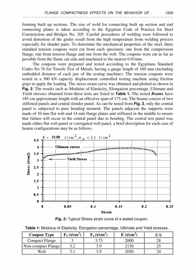
to model the flanges, web and stiffeners. The thick shell element can capture the
essential features of bending and membrane stresses of the beams and gives all
buckling modes whether global or local. Common nodes between flanges, web and
stiffeners are merged together to perform rigid connections at these nodes. As shown in
Fig. 5 only one half of the girder was modeled using the advantage of the symmetry
about the mid-span section. Three degrees of freedom were restrained for all nodes at
that section, the translations in the longitudinal direction Z (Uz=0) and the rotations
about both X and Y axes (Rotx=0 and Roty=0). The translation in the Y direction was
restrained along a line at the end support section to simulate the vertical support of the
girder. Finally, the applied loads are simulate by a serial of point loads on nodes above
the end connecting plate.
Fig. 5: Beams Boundary Conditions and Global axes directions.
4-1 Validation Of COSMOS Simulations
Under two concentrated loads, pilot runs have been performed for two simply
supported beams with corrugated webs and having the same span and flange
dimensions of the two beams with corrugated webs studied experimentally. Figures 7
and 8 show comparisons between experimental results of non-compact and compact
flanged beams with flat or corrugated web, respectively. The vertical deflection of the
central point of bottom flange has been plotted against vertical load applied as

FLANGE COMPACTNESS EFFECTS ON THE BEHAVIOR OF….
________________________________________________________________________________________________________________________________
1517
mentioned in Table 2 and shown in Figures 9 and 10. Figure 9 shows the results of
experimental works versus analytical model in case of beam with non-compact flange,
where, Fig. 10 shows the case if compact flange used. The results were found to be in
good agreement which indicated the validity of the method of modeling and solving
beams with corrugated webs and it were taken as a datum for studying the effect of
each variable on beam capacity. The same models are analyzed under the effect of
flange transversal stiffeners and thickness in the behavior of corrugated web beams up
to failure as will be discussed in the upcoming sections.
5- PARAMETRIC STUDIES AND RESULTS The proposed investigation embraced a range of parameters that influence the
compression flange buckling which including the flange restrains and the flange
thickness. To investigate the effect of these parameters, the corrugated web beam with
slenderness flange model has been solved with different combinations of values for
these parameters. The values of such parameters in each model are given in Table 2.
Comparisons between critical yielding load for corrugated web beam with non compact
flange after and before the effect of these parameters are listed in Tables 3, 4 and
plotted from Fig. 11 to Fig. 18. These results will be discussed individually in the
following sections.
5-1 Effect Of Flange Transversal Stiffeners Width
The stiffeners are positioned in the maximum outstand width as shown in
Fig. 6. In Fig. 11 load deflection relationships between beam with and without flange
transversal stiffeners are shown. These stiffeners have thickness equal to web thickness
and variable width ranged from 0.25 to 0.75 of the flange width. From that figure it can
be seen that, the deflection load curves where the stiffeners width (bst=0.25bf) equal
0.25 of flange width has no great effect and the percentage of increase which can be
reached is 0.62% as stated in Table 3. Also, it can be noticed that when the stiffeners
with thickness equal web thickness and width varied from 0.5 to 0.75 of flange width
the percentage of increase in beam yield load can varied from 4.12% to 4.64%,
respectively as mentioned in Table 3. Figure 12 shows load deflection relationships
between beam with and without flange transversal stiffeners which have variable width
and thickness equal to flange thickness. From that figure it can be seen that, the beam
yield load increased by 11.34%, 17.53% and 21.24% when the stiffeners widths are
0.25, 0.5 and 0.75 from flange width, respectively.
5-2 Effect Of Flange Thickness
The flange thickness is varied from 0.40 cm to 0.60 cm and the equivalent C/tf
values varied from 18.75 to 12.5, respectively. In Fig. 13 a comparison between beam
with C/tf = 18.75 and beam with a flange slenderness ratio varied from C/tf =15 and
C/tf = 12.5 load deflection relationships is illustrated. From that figure it can be noticed
that when the beam flange has slenderness ratio 18.75 (slender flange) the beam
capacity is less than beam with flat web by 12%, where if the flange slenderness ratio
equal to 15 (slenderness flange) the beam capacity increased by 14%, and finally if the
slenderness ratio equal 12.5 (non-compact flange) the same as flat web beam the beam
capacity increased by 38% as shown in Fig. 14.

Mohamed Dabon and A. S. Elamary ________________________________________________________________________________________________________________________________
1518
Fig. 6: Flange transversal stiffeners.
5-3 Effect Of Both Flange Stiffeners And Thickness
In this part of study, the two enhancement of flange stiffness stated above are
performed together as follows, flange transversal stiffeners with thickness equal flange
thickness and width varied from 0.25 to 0.5 of flange width are used while the flange
thickness are varied from 0.50 cm to 0.60 cm and the equivalent C/tf values varied
from 15 to 12.5 respectively. Figure 15 compares load deflection relationships
between beam flange with ((bst=0.25bf) & C/tf = 15) and beam with flat web and non-
compact flange with (C/tf = 12.5). From that figure it can be noticed that, the beam
capacity is increased by 39.69 % if it is compared with the same beam but non-
stiffened flange, which means 10% more than the same beam but with (C/tf = 15) and
without transversal stiffeners, finally the percentage of increase from flat web beam is
about 23%.
Also from the same figure and Table 4, it can be noticed that, if the beam
flange has ((bst=0.25bf) & C/tf = 12.5) the beam capacity is increased by 69.59 % if it is
compared with the same beam but non-stiffened flange, which means 12.9% more than
the same beam but with (C/tf = 12.5) and without transversal stiffeners. Finally the
percentage of increase from flat web beam is about 49.5% as illustrated in Fig. 17.

FLANGE COMPACTNESS EFFECTS ON THE BEHAVIOR OF….
________________________________________________________________________________________________________________________________
1519

Mohamed Dabon and A. S. Elamary ________________________________________________________________________________________________________________________________
1520

FLANGE COMPACTNESS EFFECTS ON THE BEHAVIOR OF….
________________________________________________________________________________________________________________________________
1521
Table 4: Effects of transversal stiffeners and flanges slenderness on beam capacity.
tf = 0.50 cm tst = 0.4& tf = 0.5 tf = 0.60 cm tst = 0.4& tf = 0.6
without Stiff With Stiff without Stiff With Stiff
12.57 13.55 15.2 16.45
29.59% 39.69% 56.70% 69.59%
tf = 0.50 cm tst = 0.4& tf = 0.5 tf = 0.60 cm tst = 0.4& tf = 0.6
without Stiff With Stiff without Stiff With Stiff
12.57 13.87 15.2 16.77
29.59% 42.99% 56.70% 72.89%
bst = 0.5 bf
bst = 0.25 bf
bst = 0.5 bf
Theor. Comparsion of yield load of C.W. beam (ton)
Theo.Exp.
10 9.7
bst = 0.25 bf
Figure 16 shows a comparison between load deflection relationships for beam
flange with ((bst=0.5bf) & C/tf = 15) and beam with flat web and non-compact flange
with (C/tf = 12.5). From that figure it can be noticed that, the beam capacity is
increased by 42.99 % if it is compared with the same beam but non-stiffened flange,
which means 13.4% more than the same beam but with (C/tf = 12.5) and without
transversal stiffeners, and finally the percentage of increased from flat web beam is
about 26%.
Also from the same figure and Table 4, it can be noticed that, if the beam
flange has ((bst=0.5bf) & C/tf = 12.5) the beam capacity is increased by 72.89 % if it is
compared with the same beam but non-stiffened flange, which means 16.19% more
than the same beam but with (C/tf = 12.5) and without transversal stiffeners, and finally
the percentage of increased from flat web beam is about 52.5% as illustrated in Fig. 18.
6- SUMMARY AND CONCLUSIONS
In this investigation, four beams with different flange compactness and web
configurations were studied experimentally and theoretically under the effect of
bending moment. The experimental work shows that, if the beams have non-compact
flanges, failure will be occurred suddenly and due to buckling in compression flanges
followed by web crippling. Finite element model was performed, using COSMOS
package, to simulate the behavior of such beam theoretically. The results obtained from
finite element compared with the experimental ones; it was found that, it is represent
the experimental results to good degree of accuracy. Parametric investigation was
performed to investigate the effect of variables such that width and thickness of flange
transversal stiffeners and/or flange thickness on the behavior of non-compact beam
with corrugated webs. The results were collected and tabulated. Based on these results
the following conclusion can be drawn:

Mohamed Dabon and A. S. Elamary ________________________________________________________________________________________________________________________________
1522
1. When flange transversal stiffeners with thickness equal web thickness and width
varied from 0.25 to 0.5 of flange width the percentage of increase in yield load
more than 12%.
2. Beam yield load increased by 11.34%, 17.53% and 21.24% when the stiffeners
widths are 0.25, 0.5 and 0.75 from flange width respectively.
3. The corrugated web beam with flange compactness at the lowest limit of non-
compact can increase the beam capacity by 38% comparing with flat web beam has
the same C/tf value.
4. The capacity of corrugated web beams with C/tf at the ceiling of slenderness and
with flange transversal stiffeners has width bst = 0.5 bf and tst = tf will be increased
by 52% if it compared with flat web beam has the same C/tf ratio.
REFERENCES [1] Abbas, H.H., Analysis and Design of Corrugated Web Plate Girder for Bridges
Using High Performance Steel, Ph.D. Dissertation Lehigh University May 2003.
[2] COSMOS/M, User's Guide manual version 2.6, S Research and Analysis C.
(1997).
[3] Easley, J.T., Buckling Formulas for Corrugated Metal Shear Diaphragms,
ASCE J. of the Struct. Div., Vol. 101, PP 1403- 1417, 1975.
[4] EGYPTIAN CODE ”EGYPTIAN CODE FOR PRACTICE FOR STEEL
CONSTRUCTION AND BRIDGES. Code No.205 (2001).
[5] Elgaaly, M., Hamilton R.W. and Seshadri, Shear Strength of Beams with
Corrugated Webs ASCE J. of the Struct. Div., Vol. 122, PP 390- 398, 1996.
[6] Elgally, M. Bending strength of steel Beams with Corrugated Webs ASCE J. of
the Struct. Div., Vol. 123, PP 772- 782, 1997.
[7] Eurocode 3 PrEN 1933-1-5 :20XX "Eurocode 3 : Design of Steel Structures.
Part 1.5 Plate Structural Elements" February 2003.
[8] Timoshenko, S.P. and Gere,J.M. Theory of elastic stability Mc Graw-Hill
Publishing Co., New York 1961.
[9] Xiaobo Wang "Behavior of Steel Members with Trapezoidally Corrugated Webs
and Tubular Flanges Under Static Loading Ph.D. Dissertation Drexel University
March 2003.
[10] Y.A.Kalid and Chan Finite Element Analysis of Corrugated Web Beams under
Bending JCSR J. Vol.58 P-P 1391-1406, 2002.

FLANGE COMPACTNESS EFFECTS ON THE BEHAVIOR OF….
________________________________________________________________________________________________________________________________
1523
SYMBOLS
The following symbols are used in this paper:
bf = Width of flange
bst = Width of stiffeners
C.W. = Corrugated web
C.F. = Compact Flange
E = Young's Modulus
Fy = Yield stress
Fu = Ultimate stress
F.W = Flat Web
H = Depth of web
N.C.F. = Non compact flange
tf = Flange thickness
tst = Transversal stiffeners thickness
tw = Web thickness
�� ذات ������ ��بدر�� � ا�� ��� ا����ات ا���� ا
�� !"# $"� ا��%���
���� ������ ��ھ��,ا ا+*(��) '��& ���% درا!��������)' .�:��89 ا+7���.ات ����در��5� ا+4��1ا0��1+ 23/��<ر ا@ ?<با+(4>4>� ذات ABCا %��D E�1D .ات��ا+7 F��Hك '! E� �5.I�+ا . &�' (��D
%� E� ����J' K<رب �'.��L K� رة>�* E�+وCا �� H�J�+.ات ا�ا+7 K3 K�1 H�J3��J343 .��O 89�: >�A+ ���B>P+وا ��J343 89: 8+ E+وC.ة ا�ا+7 K7+ج و.I3 R? أ�3<. ذات
� H�J�+ج ا.�I3 T��H3 T9B >Aا9X<ت اCو+E و+R? K7 ا+7�.ات UVW3 و+�� ��B>P+ا .
��/& '& �% B�Hذج ��)' Y1!>Z .ات�7�B��Hذج إ+4Eام ط.>[� ا+X>\I. ا+�(4دة +�HXHل +����)' K�3 8�*<.a 8�54ر+ %�P�' 2b>1B EVI<����I+إ�5.اء/�& '�& . ا ���.ات درا!�d1�+ا E��
�Hك ا+7�.ات ذات ا+�1! E� ./e' ان K7�<8 ا@ ?<ب�J343 .��O 89�: وذات ��5.I�+ا F�! ات.�d1�+ھ,ه ا h�9�و:�i+و �.ض ا F��!<تو�أ!�9% ا+�4 �9�i+ا >�I3 K��\/Cا &�/
�Hك ا+7���.ات ا+0��1/�.ا+\2b>��1 أظ��A.تو4��a ). ا+��4 �<تا+��W�F ووl��m ز>��<دة(��W+ .���ا+7* K�1]Z>�W+ا K��4Y1!>Z >A1ام اى K3 ا+(�<+1�'2b>�1B E�VI +��7ا!�4Y1اA3��I3 >< أووز><دة �<
K3 4<p'20 %E+70 إ % F�9�!�F وز><دة ا+4 �<ت D K�% ا+HrYع 4Zون 'i+ا.