Embed Size (px)
Citation preview
Fitters notesREFRIGERATION AND AIR CONDITIONING
Pressure Controls
Fitters notes Pressure Controls
2 RZ5AG202 → DKRCC.PF.C00.A1.02 / 520H0353 © Danfoss A/S (RC-CMS/MWA), 03 - 2005
Contents Page
Installation ...................................................................................................................................................................2Placing of surplus capillary tube ..........................................................................................................................4Setting ...........................................................................................................................................................................5
Low-pressure control ........................................................................................................................................5 High-pressure control ......................................................................................................................................5 Example with four compressors in parallel (R502) ................................................................................5 Setting LP for outdoor location ....................................................................................................................5
Indicative evaporating pressures (pe) for different types of systems .....................................................6
Test of contact function ..........................................................................................................................................7The correct pressure control for your system .................................................................................................9Fault location ............................................................................................................................................................11
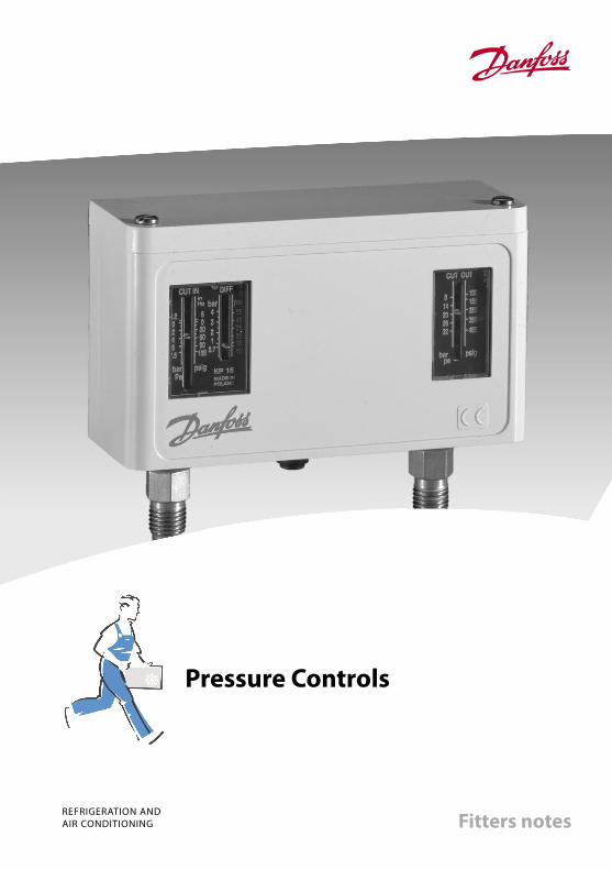
InstallationMount the KP pressure control on a bracket or on a completely flat surface.
The pressure control can also be mounted on the compressor itself.
In unfavourable conditions, an angle bracket could amplify vibration in the mounting plane. Therefore, always use a wall bracket where strong vibration occurs.
Al0_0001
Fitters notes Pressure Controls
© Danfoss A/S (RC-CMS/MWA), 03 - 2005 RZ5AG202 → DKRCC.PF.C00.A1.02 / 520H0353 3
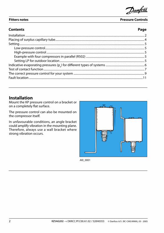
If the risk of water droplets or water spray is present, the accompanying top plate should be used. The plate increases the grade of enclosure to IP 44 and is suitable for all KP pressure controls. To obtain IP 44, the holes in the backplate of the control must be covered by mounting on either an angle bracket (060-105666) or a wall plate (060-105566).
The top plate is supplied with all units incor-porating automatic reset. It can also be used on units with manual reset, but in that case must be purchased separately (code no.: for single unit, 060-109766; for dual unit, 060-109866).
If the unit is to be used in dirty conditions or where it might be exposed to heavy spray - from above or from the side - it should be fitted with a protective cap. The cap can be used together with either an angle bracket or a wall bracket.
Al0_0007
Al0_0008
Ak0_0020
If the unit risk being exposed to heavy water influence a better grade of enclosure can be achieved when mounting the product in a special IP 55 enclosure.
The IP 55 enclosure is available for both single unit (060-033066) and dual unit (060-035066).

Fitters notes Pressure Controls
4 RZ5AG202 → DKRCC.PF.C00.A1.02 / 520H0353 © Danfoss A/S (RC-CMS/MWA), 03 - 2005
The pressure connection of the control must always be fitted to the pipe in such a way that liquid cannot collect in the bellows. This risk is present especially when:• the unit is located in a low ambient condition, e.g. in an air current,• the connection is made on the underside of the pipe.
Such liquid could damage the high-pressure control.
Consequently, compressor pulsation would not be damped and might give rise to contact chatter.
Al0_0009
Al0_0010
Placing of surplus capillary tubeSurplus capillary tube can fracture if vibration occurs and might lead to complete loss of system charge. It is therefore very important that the following rules are observed:• When mounting direct on compressor: Secure the capillary tube so that the com- pressor/control installation vibrates as a whole. Surplus capillary tube must be coiled and bound.
Al0_0011
• Other types of mounting: Coil surplus capillary tube into a loose loop. Secure the length of capillary tube between compressor and loop to the compressor. Secure the length of capillary tube between loop and pressure control to the base on which the pressure control is mounted.
In case of very strong vibrations, Danfoss steel capillary tubes with flare connection are recommended: Code no. 0.5 m = 060-016666 Code no. 1.0 m = 060-016766Code no. 1.5 m = 060-016866
Fitters notes Pressure Controls
© Danfoss A/S (RC-CMS/MWA), 03 - 2005 RZ5AG202 → DKRCC.PF.C00.A1.02 / 520H0353 5
Al0_0012
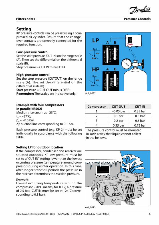
SettingKP pressure controls can be preset using a com-pressed air cylinder. Ensure that the change-over contacts are correctly connected for the required function.
Low-pressure controlSet the start pressure (CUT IN) on the range scale (A). Then set the differential on the differential scale (B). Stop pressure = CUT IN minus DIFF.
High-pressure controlSet the stop pressure (CUTOUT) on the range scale (A). The set the differential on the differential scale (B). Start pressure = CUT OUT minus DIFF.Remember: The scales are indicative only.
Example with four compressors in parallel (R502)Medium: ice cream at –25°C, t
0 ≈ –37°C,
p0 ≈ –0.5 bar,
∆p suction line corresponding to 0.1 bar.
Each pressure control (e.g. KP 2) must be set individually in accordance with the following table.
Setting LP for outdoor locationIf the compressor, condenser and receiver are situated outdoors, KP low pressure must be set to a “CUT IN” setting lower than the lowest occurring pressure (temperature around com-pressor) during winter operation. In this case, after longer standstill periods the pressure in the receiver determines the suction pressure.
Example: Lowest occurring temperature around the compressor –20°C means, for R 12, a pressure of 0.5 bar. CUT IN must be set at –24°C (corre-sponding to 0.3 bar).
Al0_0013
Compressor CUT OUT CUT IN1 –0.05 bar 0.35 bar2 0.1 bar 0.5 bar3 0.2 bar 0.6 bar4 0.35 bar 0.75 bar
The pressure control must be mounted in such a way that liquid cannot collect in the bellows.
Fitters notes Pressure Controls
6 RZ5AG202 → DKRCC.PF.C00.A1.02 / 520H0353 © Danfoss A/S (RC-CMS/MWA), 03 - 2005
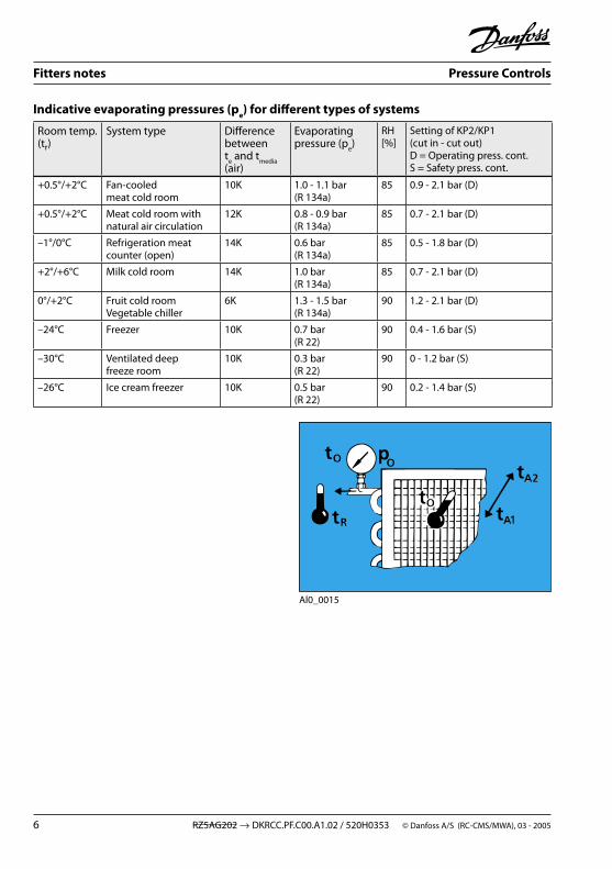
Indicative evaporating pressures (pe) for different types of systems
Al0_0015
Room temp. (tr)
System type Difference between t
e and t
media
(air)
Evaporating pressure (p
e)
RH [%]
Setting of KP2/KP1 (cut in - cut out) D = Operating press. cont. S = Safety press. cont.
+0.5°/+2°C Fan-cooled meat cold room
10K 1.0 - 1.1 bar (R 134a)
85 0.9 - 2.1 bar (D)
+0.5°/+2°C Meat cold room with natural air circulation
12K 0.8 - 0.9 bar (R 134a)
85 0.7 - 2.1 bar (D)
–1°/0°C Refrigeration meat counter (open)
14K 0.6 bar (R 134a)
85 0.5 - 1.8 bar (D)
+2°/+6°C Milk cold room 14K 1.0 bar (R 134a)
85 0.7 - 2.1 bar (D)
0°/+2°C Fruit cold room Vegetable chiller
6K 1.3 - 1.5 bar (R 134a)
90 1.2 - 2.1 bar (D)
–24°C Freezer 10K 0.7 bar (R 22)
90 0.4 - 1.6 bar (S)
–30°C Ventilated deep freeze room
10K 0.3 bar (R 22)
90 0 - 1.2 bar (S)
–26°C Ice cream freezer 10K 0.5 bar (R 22)
90 0.2 - 1.4 bar (S)

Fitters notes Pressure Controls
© Danfoss A/S (RC-CMS/MWA), 03 - 2005 RZ5AG202 → DKRCC.PF.C00.A1.02 / 520H0353 7
Al0_0018
Test of contact functionWhen the electrical leads are connected and the system is under normal operating pressure, the contact function can be tested manually.
Depending on the bellows pressure and setting, the test device must be pressed up or down.
Any reset mechanism becomes inoperative during the test.
On single units: Use the test device at top left.
On dual units: Use the test device on the left for low-pressure testing and the one at bottom right for high-pressure testing.
Warning! The contact function on a KP Pressure Control must never be tested by activating the device at top right. If this warning is ignored, the control may go out of adjustment. In the worst case function can be impaired.
Al0_0019

Fitters notes Pressure Controls
8 RZ5AG202 → DKRCC.PF.C00.A1.02 / 520H0353 © Danfoss A/S (RC-CMS/MWA), 03 - 2005
On the KP 15 dual pressure control with optional automatic or manual reset on low-pressure and high-pressure side, automatic reset must be set when servicing is being carried out. The pressure control can then automatically restart. Remember, the original reset function must be set after servicing.
The pressure control can be protected against being set on automatic reset: Simply remove the washer controlling the reset function! If the unit is to be protected against tampering, the washer can be sealed with red lacquer.
Al0_0020
Low pressure Manual reset *) Automatic reset Automatic reset Manual reset
High pressure Manual reset *) Manual reset Automatic reset Automatic reset
*) Factory setting Al0_0021
Fitters notes Pressure Controls
© Danfoss A/S (RC-CMS/MWA), 03 - 2005 RZ5AG202 → DKRCC.PF.C00.A1.02 / 520H0353 9
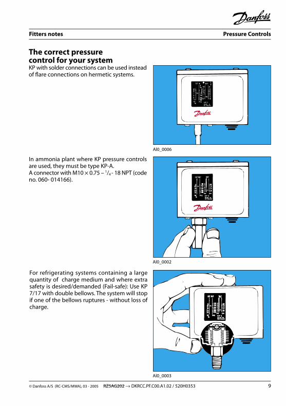
The correct pressure control for your systemKP with solder connections can be used instead of flare connections on hermetic systems.
Al0_0006
Al0_0002
Al0_0003
In ammonia plant where KP pressure controls are used, they must be type KP-A. A connector with M10 × 0.75 – 1/4
- 18 NPT (code no. 060- 014166).
For refrigerating systems containing a large quantity of charge medium and where extra safety is desired/demanded (Fail-safe): Use KP 7/17 with double bellows. The system will stop if one of the bellows ruptures - without loss of charge.

Fitters notes Pressure Controls
10 RZ5AG202 → DKRCC.PF.C00.A1.02 / 520H0353 © Danfoss A/S (RC-CMS/MWA), 03 - 2005
For systems operating with low pressure on the evaporator side, and where the pressure control must regulate (not just monitor): Use KP 2 with a small differential. An example where pressure control and thermo-stat are in series:
KP 61 regulates the temperature via compressor stop/start.
Al0_0004
Al0_0005
KP 2 stops the compressor when suction pressure becomes too low.
KP 61: CUT IN = 5°C (2.6 bar)CUT OUT = 1°C (2.2 bar)
KP 2 low pressure:CUT IN = 2.3 bar CUT OUT = 1.8 bar
For systems where KP is activated occasionally (alarm) and for systems where KP is the signal source for PLC, etc.: Use KP with gold contacts; these give good contact at low voltages.
Fitters notes Pressure Controls
© Danfoss A/S (RC-CMS/MWA), 03 - 2005 RZ5AG202 → DKRCC.PF.C00.A1.02 / 520H0353 11
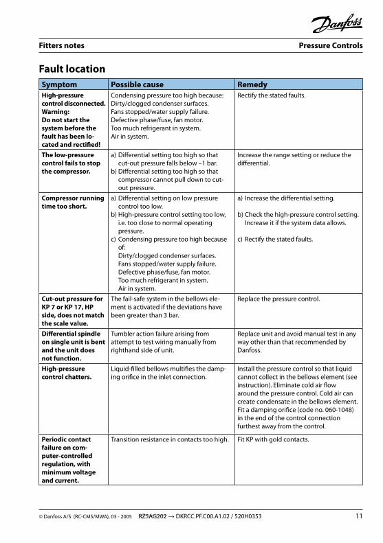
Symptom Possible cause RemedyHigh-pressure control disconnected.Warning: Do not start the system before the fault has been lo-cated and rectified!
Condensing pressure too high because:Dirty/clogged condenser surfaces.Fans stopped/water supply failure.Defective phase/fuse, fan motor.Too much refrigerant in system.Air in system.
Rectify the stated faults.
The low-pressure control fails to stopthe compressor.
a) Differential setting too high so that cut-out pressure falls below –1 bar.b) Differential setting too high so that compressor cannot pull down to cut- out pressure.
Increase the range setting or reduce thedifferential.
Compressor running time too short.
a) Differential setting on low pressure control too low.b) High-pressure control setting too low, i.e. too close to normal operating pressure.c) Condensing pressure too high because of: Dirty/clogged condenser surfaces. Fans stopped/water supply failure. Defective phase/fuse, fan motor. Too much refrigerant in system. Air in system.
a) Increase the differential setting.
b) Check the high-pressure control setting. Increase it if the system data allows. c) Rectify the stated faults.
Cut-out pressure for KP 7 or KP 17, HP side, does not match the scale value.
The fail-safe system in the bellows ele-ment is activated if the deviations have been greater than 3 bar.
Replace the pressure control.
Differential spindle on single unit is bent and the unit does not function.
Tumbler action failure arising from attempt to test wiring manually from righthand side of unit.
Replace unit and avoid manual test in any way other than that recommended by Danfoss.
High-pressure control chatters.
Liquid-filled bellows multifies the damp-ing orifice in the inlet connection.
Install the pressure control so that liquid cannot collect in the bellows element (see instruction). Eliminate cold air flow around the pressure control. Cold air can create condensate in the bellows element. Fit a damping orifice (code no. 060-1048) in the end of the control connection furthest away from the control.
Periodic contact failure on com-puter-controlled regulation, with minimum voltage and current.
Transition resistance in contacts too high. Fit KP with gold contacts.
Fault location
© Danfoss A/S (RC-CMS/MWA), 03 - 2005RZ5AG202 → DKRCC.PF.C00.A1.02 / 520H0353
The Danfoss product range for the refrigeration and air conditioning industry
Appliance ControlsGeneral temperature controls for the home appliance industry. The product range comprises CFC-free electromechanical and electronic thermostats for refrigerators and freezers produced to customer specifications as well as service thermostats for all refrigeration and freezing appliances.
Commercial CompressorsLarge hermetic reciprocating and scroll com-pressor technologies for commercial air conditioning and refrigeration. The compressors and condensing units are used in a large array of applications in both businesses. This ranges from water chillers, large packaged air conditioners as well as medium and low temperature refrigeration systems for food storage and processing.
Danfoss CompressorsHermetic compressors and fan-cooled con-densing units for refrigerators, freezers and light commercial applications such as bottle coolers and display counters. Danfoss also produces compressors for heating pump systems as well as 12 and 24 volt compressors for refrigerators and freezers used in mobile applications and solar power. The division has a leading position within energy utilisation, noise filtering and know-how about environment-friendly compressors.
Refrigeration and air conditioning controlsA comprehensive and highly reputed range of self-acting valves, electronic valves and regulators as well as system protectors and line components for the refrigeration and air conditioning market. These products include thermostatic expansion valves, solenoid valves, thermostat and pressure controls, modulation pressure regulators, filter driers, shut-off valves, sight glasses, check valves, non-return valves and water valves. Decentralised electronic systems for full regulation and control of refrigeration applications are also developed and produced at Danfoss.
Industrial ControlsProducts and customer specific solutions for industrial monitoring and controls systems based on the principles of pressure and temperature measurement, electrical power and fluid control. Products include a wide range of automatic controls for process control and regulation such as contactors and motor starters, electrically, pneumatically and temperature activated valves as well as temperature and pressure transmitters and switches.