Embed Size (px)
DESCRIPTION
Đây là van điều khiển áp suất
Citation preview
Pressure controls
7
Pressure Control Valves 1
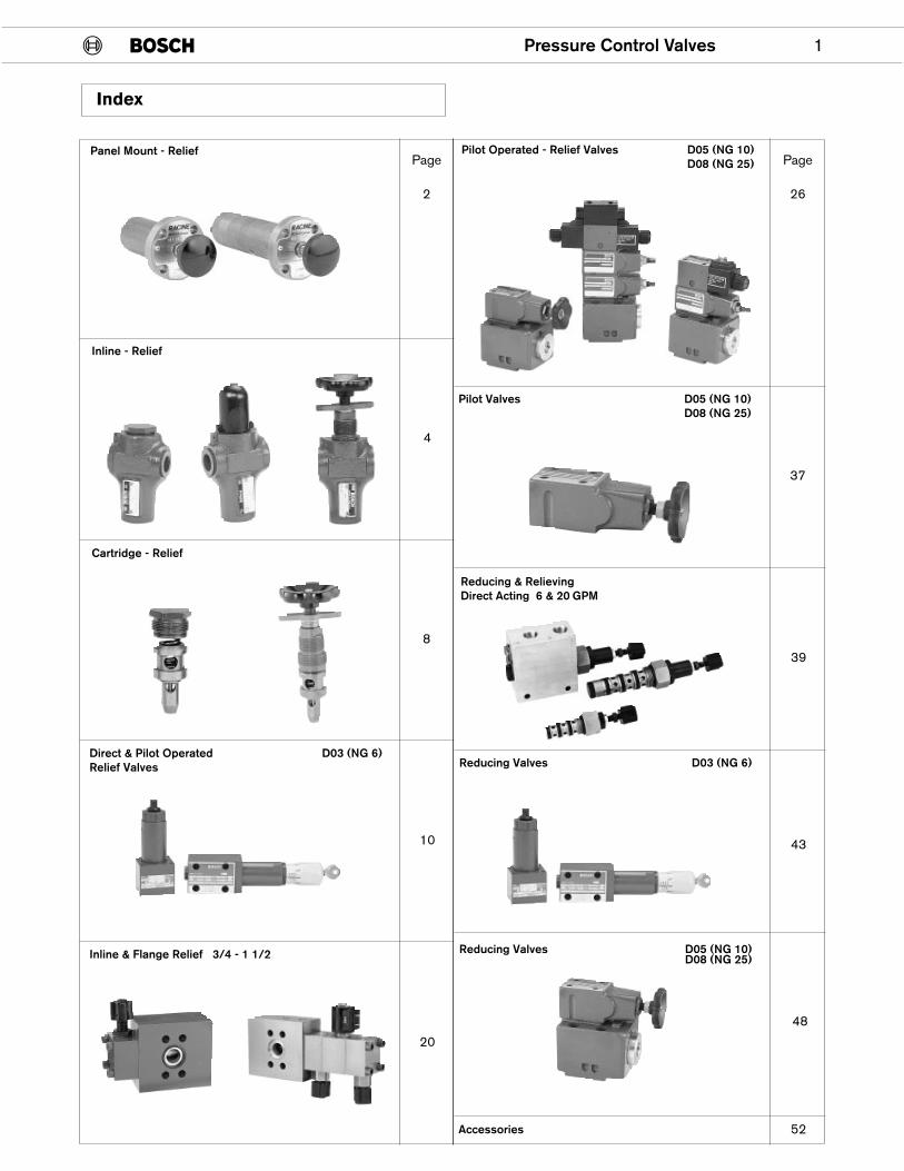
Index
Page
2
4
8
10
20
Page
26
37
39
43
48
52
Inline - Relief
Cartridge - Relief
Panel Mount - Relief
Inline & Flange Relief 3/4 - 1 1/2
Direct & Pilot Operated D03 (NG 6)Relief Valves
Pilot Operated - Relief Valves D05 (NG 10)D08 (NG 25)
Pilot Valves D05 (NG 10)D08 (NG 25)
Reducing Valves D03 (NG 6)
Reducing Valves D05 (NG 10)D08 (NG 25)
Accessories
Reducing & RelievingDirect Acting 6 & 20 GPM
2 Pressure Control Valves
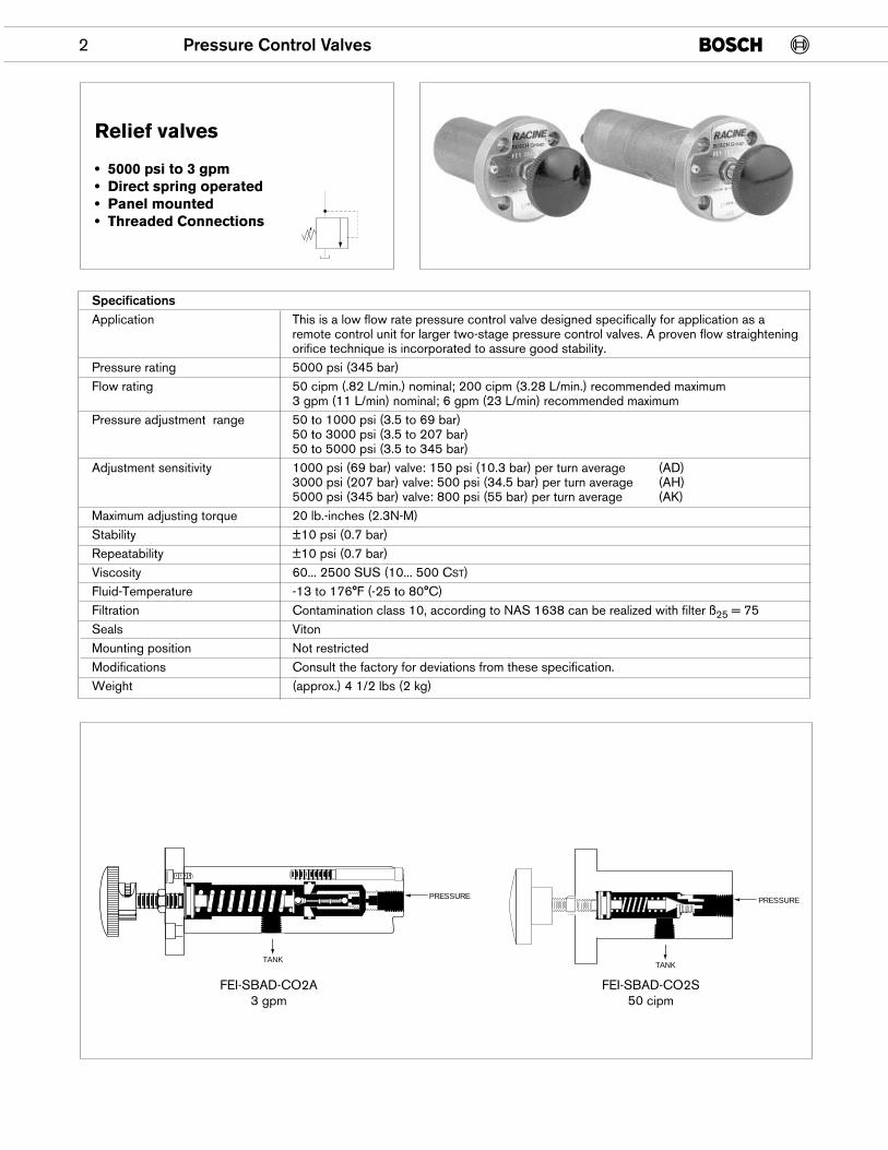
Relief valves
• 5000 psi to 3 gpm• Direct spring operated• Panel mounted• Threaded Connections
SpecificationsApplication This is a low flow rate pressure control valve designed specifically for application as a
remote control unit for larger two-stage pressure control valves. A proven flow straighteningorifice technique is incorporated to assure good stability.
Pressure rating 5000 psi (345 bar)Flow rating 50 cipm (.82 L/min.) nominal; 200 cipm (3.28 L/min.) recommended maximum
3 gpm (11 L/min) nominal; 6 gpm (23 L/min) recommended maximumPressure adjustment range 50 to 1000 psi (3.5 to 69 bar)
50 to 3000 psi (3.5 to 207 bar)50 to 5000 psi (3.5 to 345 bar)
Adjustment sensitivity 1000 psi (69 bar) valve: 150 psi (10.3 bar) per turn average (AD)3000 psi (207 bar) valve: 500 psi (34.5 bar) per turn average (AH)5000 psi (345 bar) valve: 800 psi (55 bar) per turn average (AK)
Maximum adjusting torque 20 lb.-inches (2.3N-M)Stability ±10 psi (0.7 bar)Repeatability ±10 psi (0.7 bar)Viscosity 60... 2500 SUS (10... 500 CST)Fluid-Temperature -13 to 176°F (-25 to 80°C)Filtration Contamination class 10, according to NAS 1638 can be realized with filter ß25 = 75Seals VitonMounting position Not restrictedModifications Consult the factory for deviations from these specification.Weight (approx.) 4 1/2 lbs (2 kg)
TANK
PRESSURE
TANK
PRESSURE
FEI-SBAD-CO2A3 gpm
FEI-SBAD-CO2S50 cipm
Pressure Control Valves 3
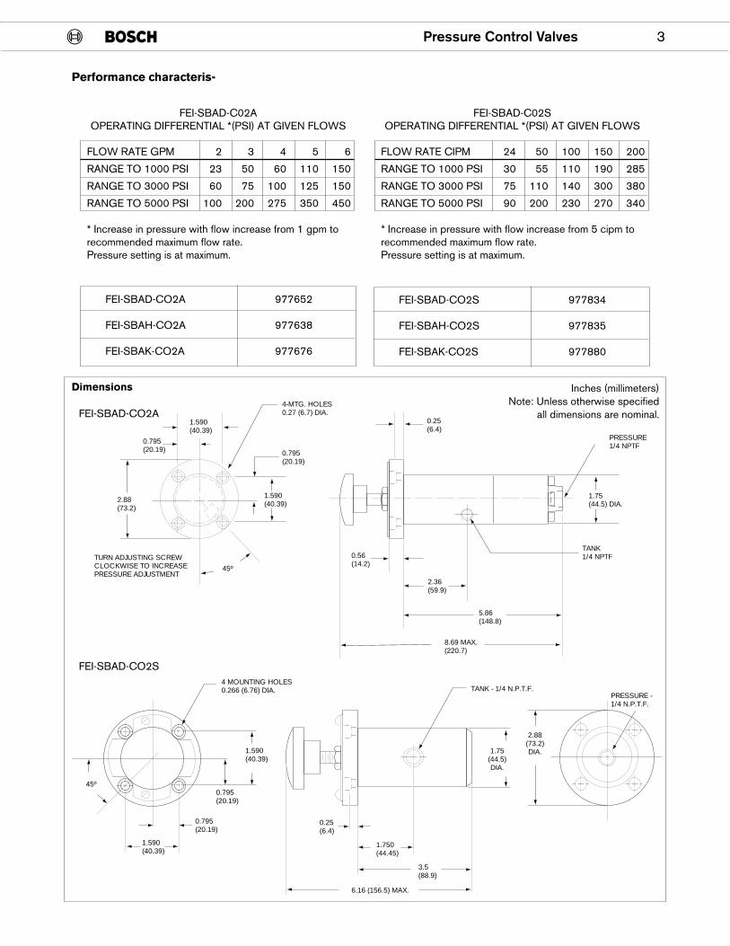
Performance characteris-
FEI-SBAD-C02SOPERATING DIFFERENTIAL *(PSI) AT GIVEN FLOWS
FLOW RATE CIPM 24 50 100 150 200
RANGE TO 1000 PSI 30 55 110 190 285
RANGE TO 3000 PSI 75 110 140 300 380
RANGE TO 5000 PSI 90 200 230 270 340
* Increase in pressure with flow increase from 5 cipm torecommended maximum flow rate.Pressure setting is at maximum.
FEI-SBAD-C02AOPERATING DIFFERENTIAL *(PSI) AT GIVEN FLOWS
FLOW RATE GPM 2 3 4 5 6
RANGE TO 1000 PSI 23 50 60 110 150
RANGE TO 3000 PSI 60 75 100 125 150
RANGE TO 5000 PSI 100 200 275 350 450
* Increase in pressure with flow increase from 1 gpm torecommended maximum flow rate.Pressure setting is at maximum.
1.590(40.39)
4-MTG. HOLES0.27 (6.7) DIA.
0.795(20.19)
0.795(20.19)
1.590(40.39)2.88
(73.2)
TURN ADJUSTING SCREWCLOCKWISE TO INCREASE PRESSURE ADJUSTMENT
45º
0.25(6.4)
PRESSURE1/4 NPTF
1.75(44.5) DIA.
TANK1/4 NPTF
5.86(148.8)
8.69 MAX.(220.7)
2.36(59.9)
0.56(14.2)
Dimensions Inches (millimeters)Note: Unless otherwise specified
all dimensions are nominal.FEI-SBAD-CO2A
FEI-SBAD-CO2S4 MOUNTING HOLES0.266 (6.76) DIA.
1.590(40.39)
1.590(40.39)
0.795(20.19)
0.795(20.19)
45º
TANK - 1/4 N.P.T.F.
3.5(88.9)
1.750(44.45)
0.25(6.4)
1.75(44.5)DIA.
6.16 (156.5) MAX.
PRESSURE - 1/4 N.P.T.F.
2.88(73.2)DIA.
FEI-SBAD-CO2A 977652
FEI-SBAH-CO2A 977638
FEI-SBAK-CO2A 977676
FEI-SBAD-CO2S 977834
FEI-SBAH-CO2S 977835
FEI-SBAK-CO2S 977880
4 Pressure Control Valves
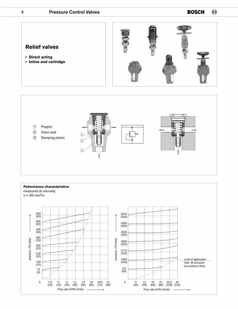
Relief valves
• Direct acting• Inline and cartridge
Flow rate GPM (I/min)
pres
sure
PS
I (ba
r)
580(40)
505(35)
365(25)
218(15)
73(5)
290(20)
145(10)
0 2.5(10)
5(15)
8(30)
11(40)
13(50)
16(60)
18.5(70)
21(80)
435(30)
Flow rate GPM (I/min)
pres
sure
PS
I (ba
r)
3075(350)
3625(250)
2175(150)
725(50)
2900(200)
1450(100)
0 5(20)
11(40)
16(60)
21(80)
26.5(100)
32(120)
4350(300)
Limit of application(min. lift pressureaccording to flow)
1
2
3
1 Poppet
2 Valve seat
3 Damping piston
Peformance characteristicsmeasured at viscosityν = 35 mm2/s
Pressure Control Valves 5
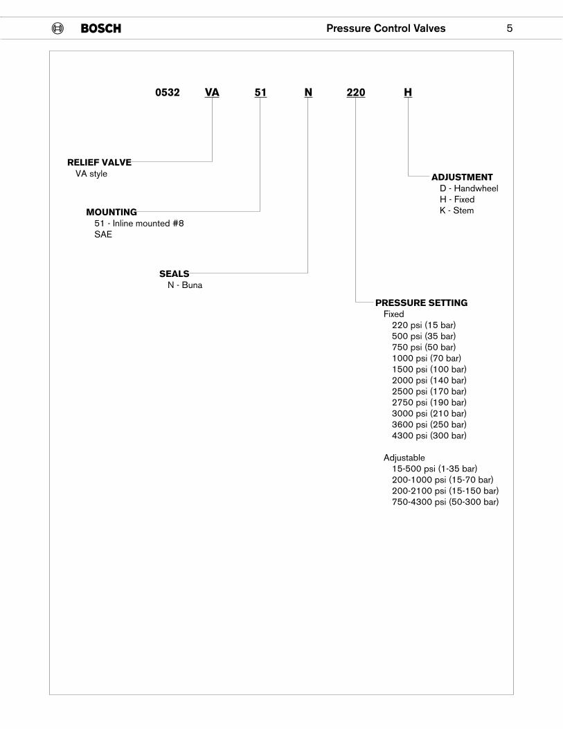
RELIEF VALVEVA style
MOUNTING51 - Inline mounted #8SAE
SEALSN - Buna
PRESSURE SETTINGFixed
220 psi (15 bar)500 psi (35 bar)750 psi (50 bar)1000 psi (70 bar)1500 psi (100 bar)2000 psi (140 bar)2500 psi (170 bar)2750 psi (190 bar)3000 psi (210 bar)3600 psi (250 bar)4300 psi (300 bar)
Adjustable15-500 psi (1-35 bar)200-1000 psi (15-70 bar)200-2100 psi (15-150 bar)750-4300 psi (50-300 bar)
ADJUSTMENTD - HandwheelH - FixedK - Stem
0532 VA 51 N 220 H
6 Pressure Control Valves
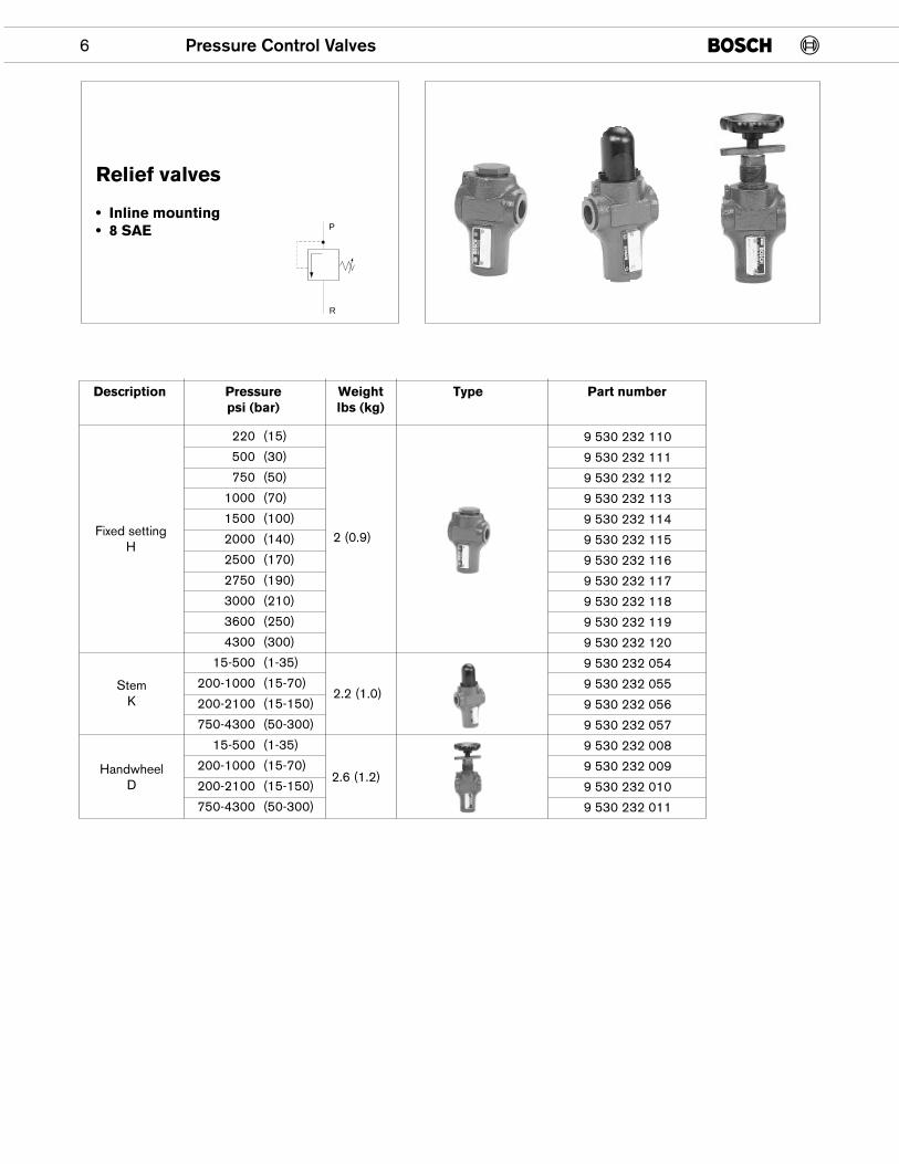
Relief valves
• Inline mounting• 8 SAE
Description Pressure Weight Type Part numberpsi (bar) lbs (kg)
220 (15)
500 (30)
750 (50)
1000 (70)
1500 (100)
2000 (140)
2500 (170)
2750 (190)
3000 (210)
3600 (250)
4300 (300)
15-500 (1-35)
200-1000 (15-70)
200-2100 (15-150)
750-4300 (50-300)
15-500 (1-35)
200-1000 (15-70)
200-2100 (15-150)
750-4300 (50-300)
Fixed settingH
2 (0.9)
2.2 (1.0)
2.6 (1.2)
StemK
HandwheelD
9 530 232 110
9 530 232 111
9 530 232 112
9 530 232 113
9 530 232 114
9 530 232 115
9 530 232 116
9 530 232 117
9 530 232 118
9 530 232 119
9 530 232 120
9 530 232 054
9 530 232 055
9 530 232 056
9 530 232 057
9 530 232 008
9 530 232 009
9 530 232 010
9 530 232 011
R
P
Pressure Control Valves 7
�������
���
�
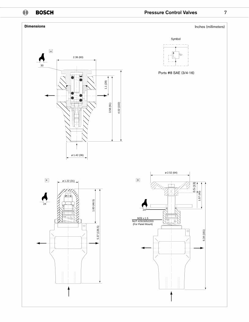
2.36 (60)
3.58
(91
)
1.1
(28)
4.02
(10
2)
ø 1.42 (36)
30
Symbol
�������1.83
(46
.5)
5.37
(13
6.5)
ø 1.22 (31)
24
1.57
(40
)0.5
(13)
6.34
(16
1)
24
ø 2.52 (64)
M26 x 1.5NUT #2915052203(For Panel Mount)
����
��������� ������������������
K D
H
Dimensions Inches (millimeters)
Ports #8 SAE (3/4-16)
8 Pressure Control Valves
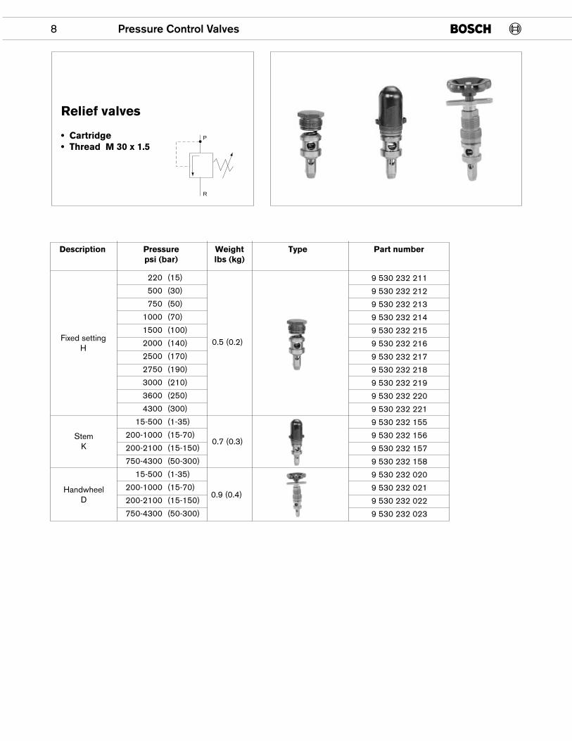
Relief valves
• Cartridge• Thread M 30 x 1.5
Description Pressure Weight Type Part numberpsi (bar) lbs (kg)
220 (15)
500 (30)
750 (50)
1000 (70)
1500 (100)
2000 (140)
2500 (170)
2750 (190)
3000 (210)
3600 (250)
4300 (300)
15-500 (1-35)
200-1000 (15-70)
200-2100 (15-150)
750-4300 (50-300)
15-500 (1-35)
200-1000 (15-70)
200-2100 (15-150)
750-4300 (50-300)
Fixed settingH
0.5 (0.2)
0.7 (0.3)
0.9 (0.4)
StemK
HandwheelD
9 530 232 211
9 530 232 212
9 530 232 213
9 530 232 214
9 530 232 215
9 530 232 216
9 530 232 217
9 530 232 218
9 530 232 219
9 530 232 220
9 530 232 221
9 530 232 155
9 530 232 156
9 530 232 157
9 530 232 158
9 530 232 020
9 530 232 021
9 530 232 022
9 530 232 023
P
R
Pressure Control Valves 9
�������������
���������
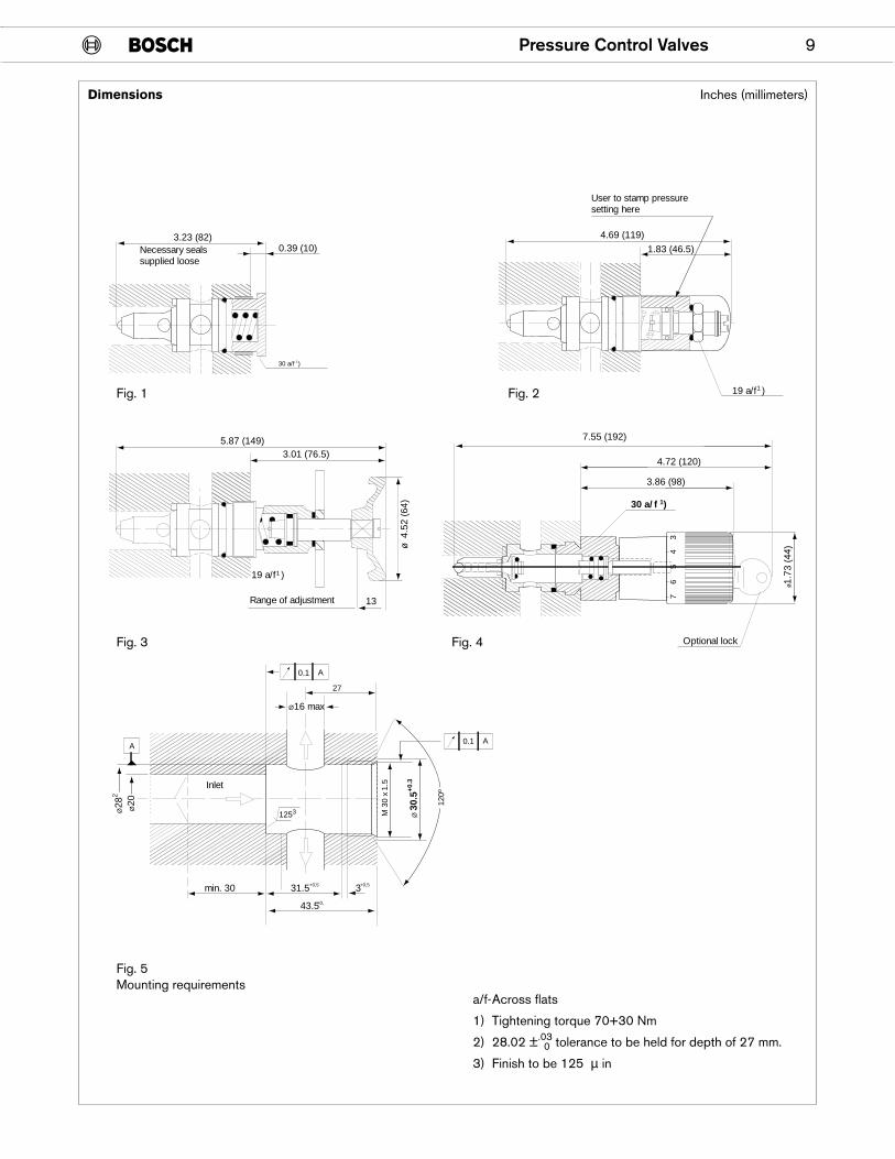
3.23 (82)Necessary sealssupplied loose
0.39 (10)
���������
4.69 (119)
User to stamp pressuresetting here
1.83 (46.5)
����������
5.87 (149)3.01 (76.5)����� 13
ø 4
.52
(64)
Range of adjustment � 73
45
6
7.55 (192)
4.72 (120)
3.86 (98)
Optional lock
ø1.7
3 (4
4)
������
0.1 A
0.1 A
M 3
0 x
1.5
120º
27
Ø16 max
A
Ø28
2
Ø20
Inlet
1253
min. 30 31.5 3+0,5 +0,5
+0,43.5
19 a/f )1
30 a/f )1
19 a/f )1
Ø 3
0.5+
0.3
30 a/f 1)
Dimensions
a/f-Across flats
1) Tightening torque 70+30 Nm
2) 28.02 ±.030 tolerance to be held for depth of 27 mm.
3) Finish to be 125 µ in
Fig. 5Mounting requirements
Fig. 1 Fig. 2
Fig. 3 Fig. 4
Inches (millimeters)
10 Pressure Control Valves
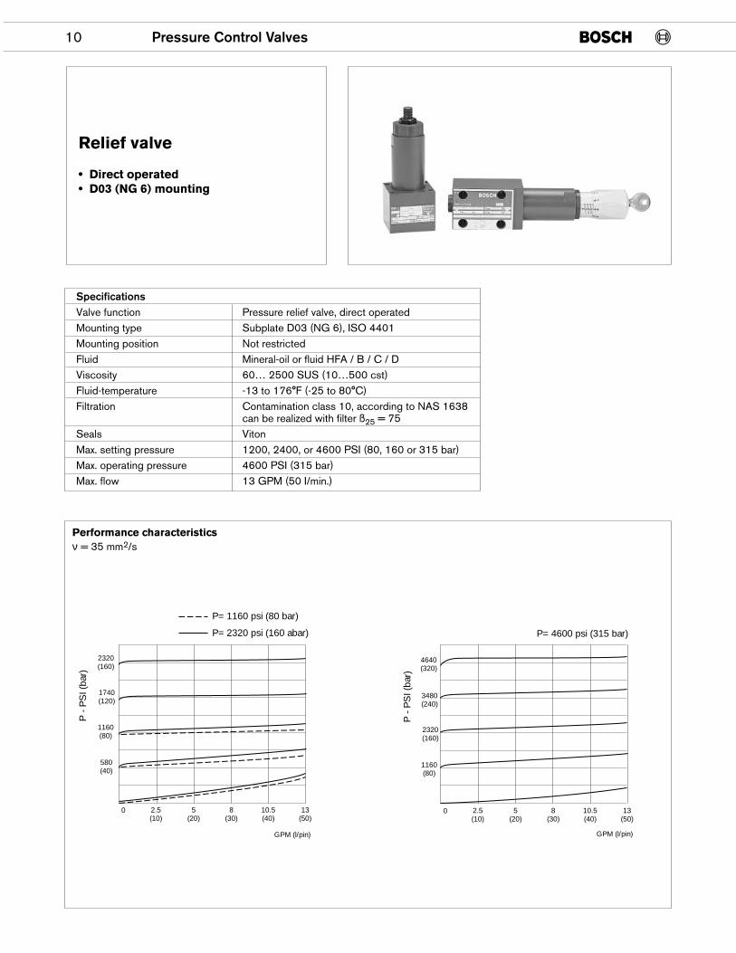
Relief valve
• Direct operated• D03 (NG 6) mounting
SpecificationsValve function Pressure relief valve, direct operatedMounting type Subplate D03 (NG 6), ISO 4401Mounting position Not restrictedFluid Mineral-oil or fluid HFA / B / C / DViscosity 60… 2500 SUS (10…500 cst)Fluid-temperature -13 to 176°F (-25 to 80°C)Filtration Contamination class 10, according to NAS 1638
can be realized with filter ß25 = 75Seals VitonMax. setting pressure 1200, 2400, or 4600 PSI (80, 160 or 315 bar)Max. operating pressure 4600 PSI (315 bar)Max. flow 13 GPM (50 I/min.)
P -
PS
I (ba
r)
1740(120)
1160(80)
0
580(40)
2.5(10)
5(20)
8(30)
10.5(40)
13(50)
2320(160)
P -
PS
I (ba
r)
3480(240)
2320(160)
1160(80)
4640(320)
0 2.5(10)
5(20)
8(30)
10.5(40)
13(50)
GPM (l/pin) GPM (l/pin)
P= 1160 psi (80 bar)
P= 2320 psi (160 abar) P= 4600 psi (315 bar)
Performance characteristicsν = 35 mm2/s
Pressure Control Valves 11
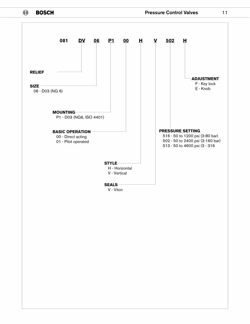
RELIEF
MOUNTINGP1 - D03 (NG6, ISO 4401)
BASIC OPERATION00 - Direct acting01 - Pilot operated
STYLEH - HorizontalV - Vertical
SEALSV - Viton
SIZE06 - D03 (NG 6)
PRESSURE SETTING516 - 50 to 1200 psi (3-80 bar)502 - 50 to 2400 psi (3-160 bar)513 - 50 to 4600 psi (3 - 316
ADJUSTMENTF - Key lockE - Knob
081 DV 06 P1 00 H V 502 H
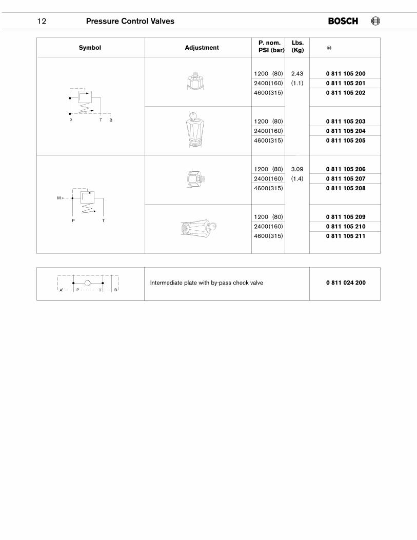
1200 (80) 2.43 0 811 105 200
2400(160) (1.1) 0 811 105 201
4600(315) 0 811 105 202
1200 (80) 0 811 105 203
2400(160) 0 811 105 204
4600(315) 0 811 105 205
1200 (80) 3.09 0 811 105 206
2400(160) (1.4) 0 811 105 207
4600(315) 0 811 105 208
1200 (80) 0 811 105 209
2400(160) 0 811 105 210
4600(315) 0 811 105 211
12 Pressure Control Valves
P T B
P T
M
Symbol AdjustmentP. nom.PSI (bar)
Lbs.(Kg)
Intermediate plate with by-pass check valve 0 811 024 200P T BAT
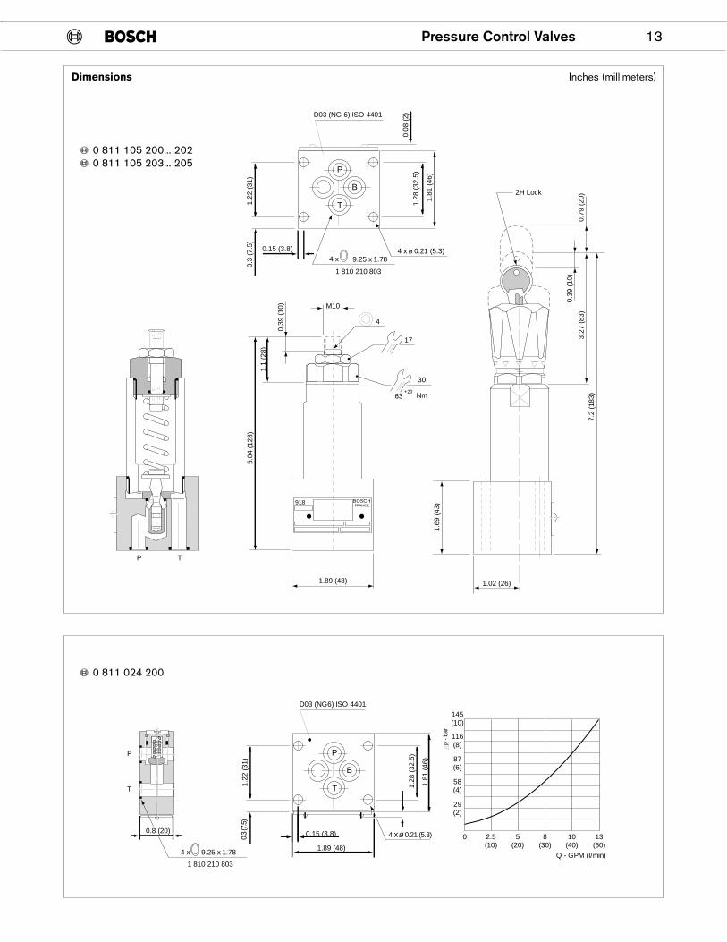
Pressure Control Valves 13
918 BOSCHFRANCE
M10
0.39
(10
)
1.1
(28)
5.04
(12
8)
1.89 (48)
4
17
30
63 Nm+20
1.02 (26)7.
2 (1
83)
1.69
(43
)
P T
0.08
(2)D03 (NG 6) ISO 4401
4 x 9.25 x 1.78
1 810 210 803
4 x ø 0.21 (5.3)
P
T
B
0.39
(10
)
0.79
(20
)3.
27 (
83)
2H Lock
1.2
8 (3
2.5)
1.8
1 (4
6)
1.2
2 (3
1) 0
.3 (
7.5) 0.15 (3.8)
P
T
0.8 (20)
4 x 9.25 x 1.78
1 810 210 803
D03 (NG6) ISO 4401145(10)
116(8)
87(6)
58(4)
29(2)
0 2.5(10)
5(20)
8(30)
10(40)
13(50)
p -
bar
4 x ø 0.21 (5.3)
P
T
B
1.22
(31
)0.
3 (7
.5)
0.15 (3.8)
1.89 (48)
1.28
(32
.5)
1.81
(46
)
Q - GPM (I/min)
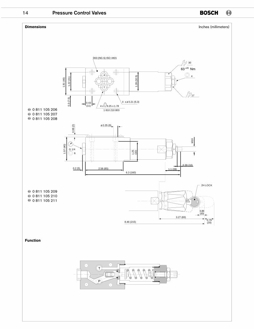
Dimensions
0 811 105 200... 2020 811 105 203... 205
0 811 024 200
Inches (millimeters)
14 Pressure Control Valves
D03 (NG 6) ISO 4401
4 x 9.25 x 1.78
1 810 210 803
4 x ø 0.21 (5.3)
P
T
30
4
17
0.2 (5)
6.3 (160)
M10
ø 0.35 (9)
0.08
(2)
G 1/4
6
0.39(10)
0.79(20)
3.27 (83)
8.46 (215)
2H LOCK
P
T
2.56 (65)0.39 (10)
1.1 (28)
1.57
(40
)1.
81 (
46)
1.22
(31
)
1.28
(32
.5)
0.43(11)0.
3 (7
.5)
1.25
(32)
Dimensions
Function
0 811 105 2060 811 105 2070 811 105 208
0 811 105 2090 811 105 2100 811 105 211
Inches (millimeters)
Pressure Control Valves 15
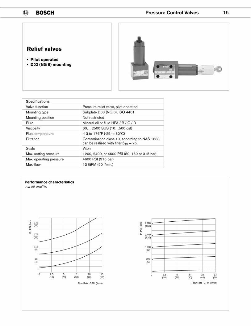
Relief valves
• Pilot operated• D03 (NG 6) mounting
SpecificationsValve function Pressure relief valve, pilot operatedMounting type Subplate D03 (NG 6), ISO 4401Mounting position Not restrictedFluid Mineral-oil or fluid HFA / B / C / DViscosity 60… 2500 SUS (10…500 cst)Fluid-temperature -13 to 176°F (-25 to 80°C)Filtration Contamination class 10, according to NAS 1638
can be realized with filter ß25 = 75Seals VitonMax. setting pressure 1200, 2400, or 4600 PSI (80, 160 or 315 bar)Max. operating pressure 4600 PSI (315 bar)Max. flow 13 GPM (50 I/min.)
232(16)
174(12)
116(8)
58(4)
0 2.5(10)
5(20)
8(30)
10(40)
13(50)
P -
PS
I (ba
r)
580(40)
1160(80)
1740(120)
2320(160)
P- P
SI (
bar)
0 2.5(10)
5(20)
8(30)
10(40)
13(50)
Flow Rate GPM (l/min) Flow Rate GPM (l/min)
Performance characteristicsν = 35 mm2/s
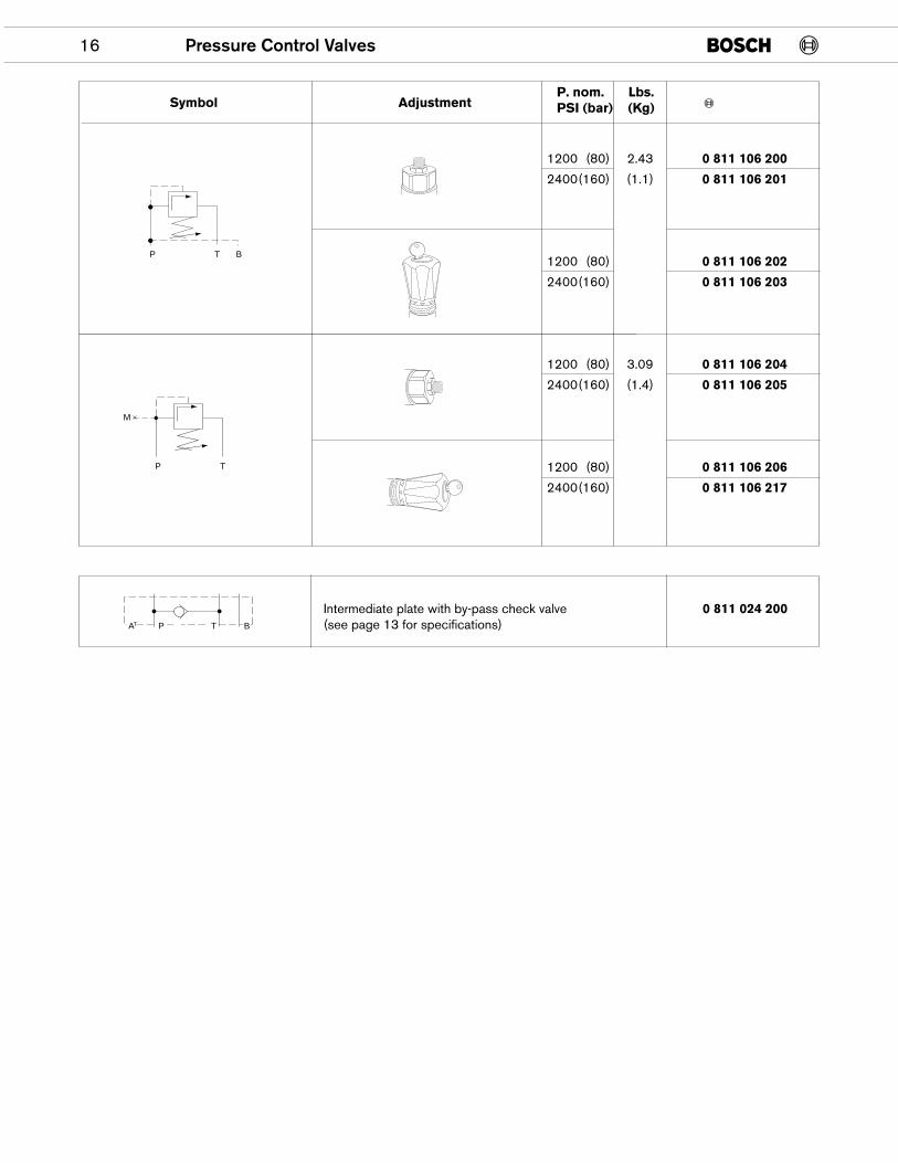
16 Pressure Control Valves
1200 (80) 2.43 0 811 106 200
2400(160) (1.1) 0 811 106 201
1200 (80) 0 811 106 202
2400(160) 0 811 106 203
1200 (80) 3.09 0 811 106 204
2400(160) (1.4) 0 811 106 205
1200 (80) 0 811 106 206
2400(160) 0 811 106 217
P T B
P T
M
Symbol AdjustmentP. nom.PSI (bar)
Lbs.(Kg)
Intermediate plate with by-pass check valve 0 811 024 200(see page 13 for specifications)AT BP T
Pressure Control Valves 17
918 BOSCHFRANCE
M10
1.89 (48)
4
17
30
63 Nm+20
2H Lock
D03 (NG 6) ISO 4401
P
B
T
4 X 9.25 X 1.781 810 210 803
1.02 (26)
0.08
(2)
4 x ø 0.21 (5.3)
1.2
8 (3
2.5)
1.81
(46
)
1.22
(31
)0.
3 (7
.5)
0.15 (3.8)
7.2
(183
)
0.39
(10
)
0.79
(20
)3.
27 (
83)
0.39
(10
)
1.1
(28)
5.04
(12
8)
1.69
(43
)
P T
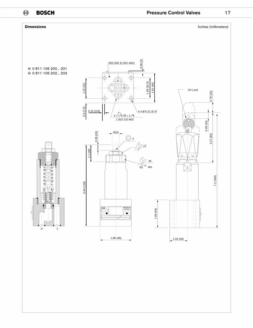
0 811 106 200... 2010 811 106 202... 203
Dimensions Inches (millimeters)
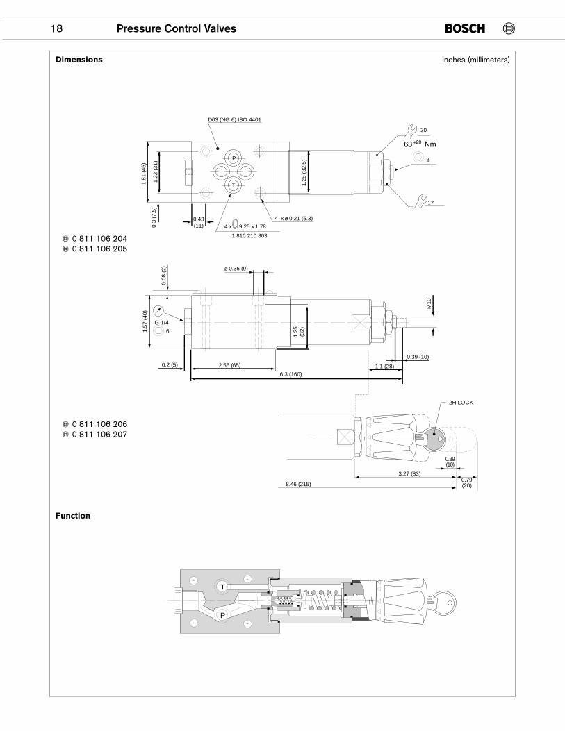
18 Pressure Control Valves
P
T
D03 (NG 6) ISO 4401
4 x 9.25 x 1.78
1 810 210 803
P
T
30
4
17
M10
G 1/4
6
2H LOCK
0.39(10)
0.79(20)
3.27 (83)
8.46 (215)
0.2 (5)
6.3 (160)
ø 0.35 (9)
0.08
(2)
2.56 (65)
0.39 (10)
1.1 (28)
1.57
(40
)
4 x ø 0.21 (5.3)
1.81
(46
)
1.22
(31
)
1.28
(32
.5)
0.43(11)0.
3 (7
.5)
1.25
(32)
Dimensions
Function
0 811 106 2040 811 106 205
0 811 106 2060 811 106 207
Inches (millimeters)
Pressure Control Valves 19
������������������������������������
�@�À�@�À�@�À�@�À�@�À�@�À�@�À�@�À�@�À�@�À�@�À�@�À�@�À�@�À�@�À�@�À�@�À�@�À�@�À�@�À�@�À�@�À�@�À�@�À�@�À�@�À�@�À�@�À�@�À�@�À�@�À�@�À�@�À�@�À�@�À�@�À�@�À�@�À�@�À�@�À�@�À�@�À�@�À�@�À�@�À�@�À�@�À�@�À�@�À�@�À�@�À�����
���������
��������������������
01
�������������������������������������@�À�@�À�@�À�@�À�@�À�@�À�@�À�@�À�@�À�@�À�@�À�@�À�@�À�@�À�@�À�@�À�@�À�@�À�@�À�@�À�@�À�@�À�@�À�@�À�@�À�@�À�@�À�@�À�@�À�@�À�@�À�@�À�@�À�@�À�@�À�@�À�@�À�@�À�@�À�@�À�@�À�@�À�@�À�@�À�@�À�@�À�@�À�@�À�@�À�@�À�@�À��
���
���������
��������������������
02
06
05
03
04
M4 x 12 3
3 Nm
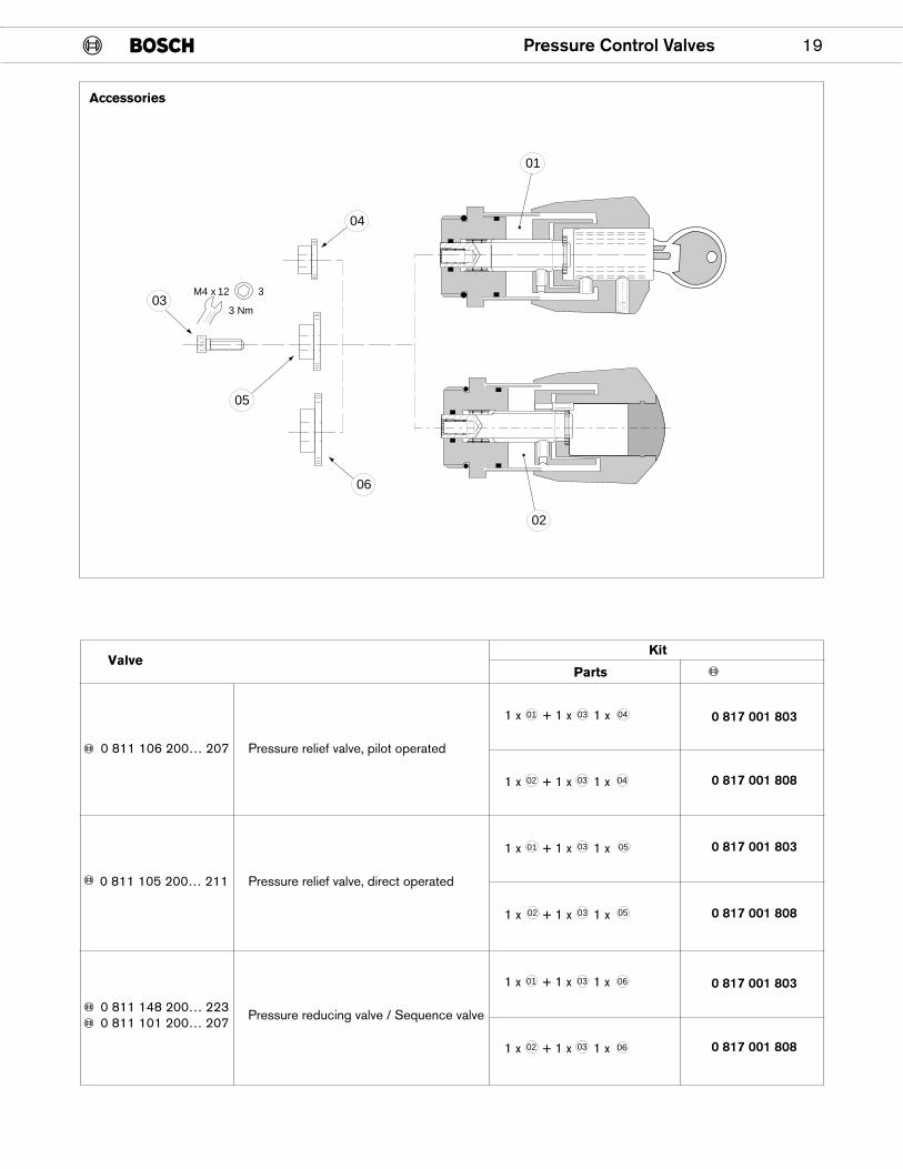
ValveKit
Parts
0 817 001 803
0 817 001 808
0 817 001 803
0 817 001 808
1 x + 1 x 1 x
Pressure relief valve, pilot operated0 811 106 200… 207
0 811 105 200… 211 Pressure relief valve, direct operated
1 x + 1 x 1 x
1 x + 1 x 1 x
1 x + 1 x 1 x
01
02
02 05
0501
03 04
0403
03
03
0 817 001 803
0 817 001 808
1 x + 1 x 1 x
Pressure reducing valve / Sequence valve0 811 148 200… 2230 811 101 200… 207
1 x + 1 x 1 x
01
02
03 06
0603
Accessories
20 Pressure Control Valves
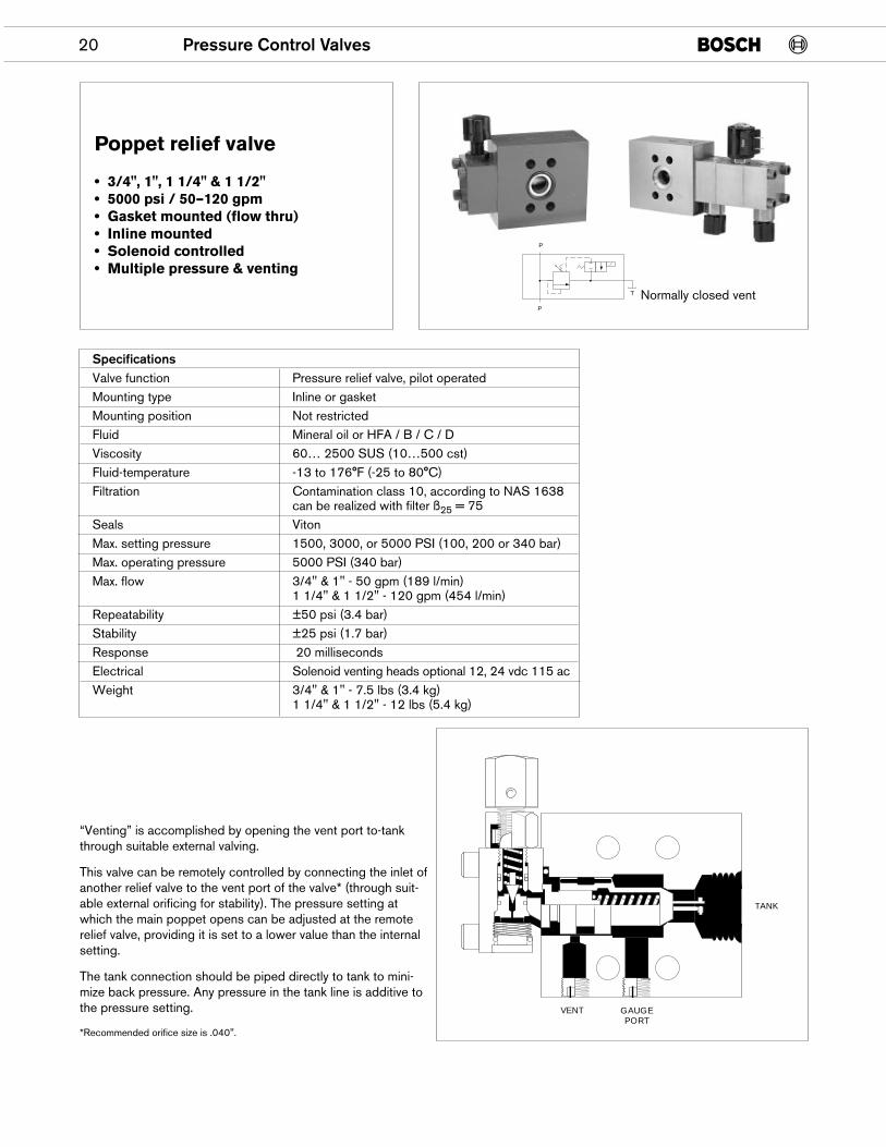
Poppet relief valve
• 3/4", 1", 1 1/4" & 1 1/2"• 5000 psi / 50–120 gpm• Gasket mounted (flow thru)• Inline mounted• Solenoid controlled• Multiple pressure & venting
VENT
TANK
GAUGEPORT
SpecificationsValve function Pressure relief valve, pilot operatedMounting type Inline or gasketMounting position Not restrictedFluid Mineral oil or HFA / B / C / DViscosity 60… 2500 SUS (10…500 cst)Fluid-temperature -13 to 176°F (-25 to 80°C)Filtration Contamination class 10, according to NAS 1638
can be realized with filter ß25 = 75Seals VitonMax. setting pressure 1500, 3000, or 5000 PSI (100, 200 or 340 bar)Max. operating pressure 5000 PSI (340 bar)Max. flow 3/4" & 1" - 50 gpm (189 l/min)
1 1/4" & 1 1/2" - 120 gpm (454 l/min)Repeatability ±50 psi (3.4 bar)Stability ±25 psi (1.7 bar)Response 20 millisecondsElectrical Solenoid venting heads optional 12, 24 vdc 115 acWeight 3/4" & 1" - 7.5 lbs (3.4 kg)
1 1/4" & 1 1/2" - 12 lbs (5.4 kg)
“Venting” is accomplished by opening the vent port to-tankthrough suitable external valving.
This valve can be remotely controlled by connecting the inlet ofanother relief valve to the vent port of the valve* (through suit-able external orificing for stability). The pressure setting atwhich the main poppet opens can be adjusted at the remoterelief valve, providing it is set to a lower value than the internalsetting.
The tank connection should be piped directly to tank to mini-mize back pressure. Any pressure in the tank line is additive tothe pressure setting.
*Recommended orifice size is .040".
P
P
T Normally closed vent
Pressure Control Valves 21
VENT PRESSURE VS. FLOW3/4" RELIEF VALVES
BA
R
PS
I
160
140
120
100
80
60
40
20
0
1
3
5
7
9
11
0 30 60 90 120 150 180 210 L/min
VE
NT
PR
ES
SU
RE
FLOW
0 10 20 30 40 50 60 GPM
LOW VENT 25 PSI
HIGH VENT 65 PSI
VENT PRESSURE VS. FLOW1-1/4" RELIEF VALVESB
AR
PS
I
400
300
200
100
00
5
10
15
20
25
0 50 100 150 120 150 180 350 L/min
PR
ES
SU
RE
FLOW
0 20 40 60 80 100 GPM
65 PSI VENT
25 PSI VENT
3000200
150
100
50
0
2500
2000
1500
1000
500
0 10 20 30
300
40 50 60
60 90 120 150 180 210 240 L/min
70 GPM
FLOW
SY
STE
M P
RE
SS
UR
E
BA
R
PS
I
3/4", 1", 1-1/4" 3000 PSI FLANGE3/4", 1", 6000 PSI FLANGE
3000 PSI SETTING
2000 PSI SETTING
1000 PSI SETTING
MIN. SETTING
4000 PSI SETTING
3000 PSI SETTING
2000 PSI SETTING
1500 PSI SETTING
500 PSI SETTING
MIN. SETTING (125 PSI)
1000 PSI SETTING
0
0 50 100 150 200 250 300 350
0
1000
2000
3000
4000
5000
300
250
200
150
100
50
020 40 60 80 100 GPM
PS
I
BA
R
PR
ES
SU
RE
L/min
FLOW
1-1/2" 3000 PSI FLANGE1-1/4" 5000 PSI VALVE (6000 PSI FLANGE)
PR
ES
SU
RE
BA
R
PS
I SENSITIVITY CURVES(ALL SIZES)
NUMBER OF ADJUSTMENT TURNS
0
250
500
750
1000
1250
1500
1750
2000
2250
2500
2750
3000200
180
160
140
120
100
80
60
40
20
01 2 3 4 5
LOW
HIGH
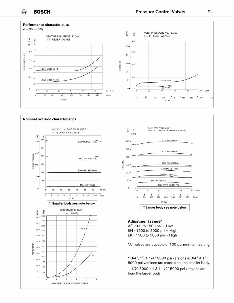
Performance characteristicsν = 35 mm2/s
Nominal override characteristics
Adjustment range*AE -100 to 1500 psi — LowEH - 1500 to 3000 psi — HighEK - 1500 to 5000 psi — High
*All valves are capable of 100 psi minimum setting.
**3/4", 1", 1 1/4" 3000 psi versions & 3/4" & 1"5000 psi versions are made from the smaller body.
1 1/2" 3000 psi & 1 1/2" 5000 psi versions arefrom the larger body.
** Smaller body see note below** Larger body see note below
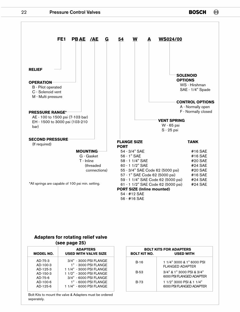
22 Pressure Control Valves
RELIEF
SECOND PRESSURE(If required)
MOUNTINGG - GasketT - Inline
(threadedconnections)
OPERATIONB - Pilot operatedC - Solenoid ventM - Multi pressure
PRESSURE RANGE*AE - 100 to 1500 psi (7-103 bar)EH - 1500 to 3000 psi (103-210bar)
FLANGE SIZE TANKPORT
54 - 3/4" SAE #16 SAE56 - 1" SAE #16 SAE58 - 1 1/4" SAE #20 SAE60 - 1 1/2" SAE #24 SAE55 - 3/4" SAE Code 62 (5000 psi) #20 SAE57 - 1" SAE Code 62 (5000 psi) #16 SAE59 - 1 1/4" SAE Code 62 (5000 psi) #24 SAE61 - 1 1/2" SAE Code 62 (5000 psi) #24 SAE
PORT SIZE (Inline mounted)54 - #12 SAE56 - #16 SAE
SOLENOIDOPTIONS
WS - HirshmanSAE - 1/4" Spade
CONTROL OPTIONSA - Normally openF - Normally closed
VENT SPRINGW - 65 psiS - 25 psi
FE1 PB AE /AE G 54 W A WS024/00
*All springs are capable of 100 psi min. setting.
ADAPTERSMODEL NO. USED WITH VALVE SIZE
AD-75-3 3/4" - 3000 PSI FLANGEAD-100-3 1" - 3000 PSI FLANGEAD-125-3 1 1/4" - 3000 PSI FLANGEAD-150-3 1 1/2" - 3000 PSI FLANGEAD-75-6 3/4" - 6000 PSI FLANGEAD-100-6 1" - 6000 PSI FLANGEAD-125-6 1 1/4" - 6000 PSI FLANGE
Bolt Kits to mount the valve & Adapters must be orderedseperately.
BOLT KITS FOR ADAPTERSBOLT KIT NO. USED WITH
B-16 1 1/4" 3000 & 1" 6000 PSIFLANGED ADAPTER
B-53 3/4" & 1" 3000 PSI & 3/4"6000 PSI FLANGED ADAPTER
B-73 1 1/2" 3000 PSI & 1 1/4"6000 PSI FLANGED ADAPTER
Adapters for rotating relief valve(see page 25)
Pressure Control Valves 23
3.38(85.7)
4.50(114.3)
1/4-18 NPTF GAGE PORT PLUGGED
.41 (10.3) THRU MTGHOLES 2-PLACES
2.50(63.5)
1.25(31.8)
3.50(88.9)
1.81(46.0)
3.88(98.4)1.56
(39.7)
1.75(44.5)
4.66(118.3) Max.
1.81
.62(15.9)
1.00(25.4)
2.00(50.8)
1/4-18 NPTFVENT PORT PLUGGED
VE
NT
#16 SAETANK PORT
#16 SAEINLET PORT 2 SIDES
3.62(92.1)
4.75(120.7)
1.56(39.7)
.41 (10.3) THRU MTGHOLE 2-PLACES
3.00(76.2)
1.50(38.1)
5.38(136.6)
2.33(59.1)
.86(21.9)
2.00(50.8)
5.53(140.5)MAX.
2.00(50.8)
1.25(31.8)
2.50(63.5)
#20 SAE INLET PORT 2-SIDES
#20 SAE TANK PORT
1/4-18 NPTFVENT PORT PLUGGED
1/4-18 NPTF GAGEPORT PLUGGED
VE
NT
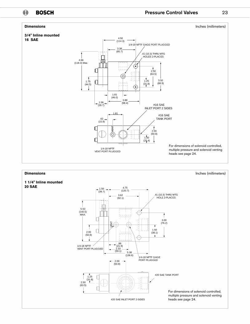
Dimensions
3/4" Inline mounted16 SAE
Inches (millimeters)
Dimensions
1 1/4" Inline mounted20 SAE
Inches (millimeters)
For dimensions of solenoid controlled,multiple pressure and solenoid ventingheads see page 24.
For dimensions of solenoid controlled,multiple pressure and solenoid ventingheads see page 24.
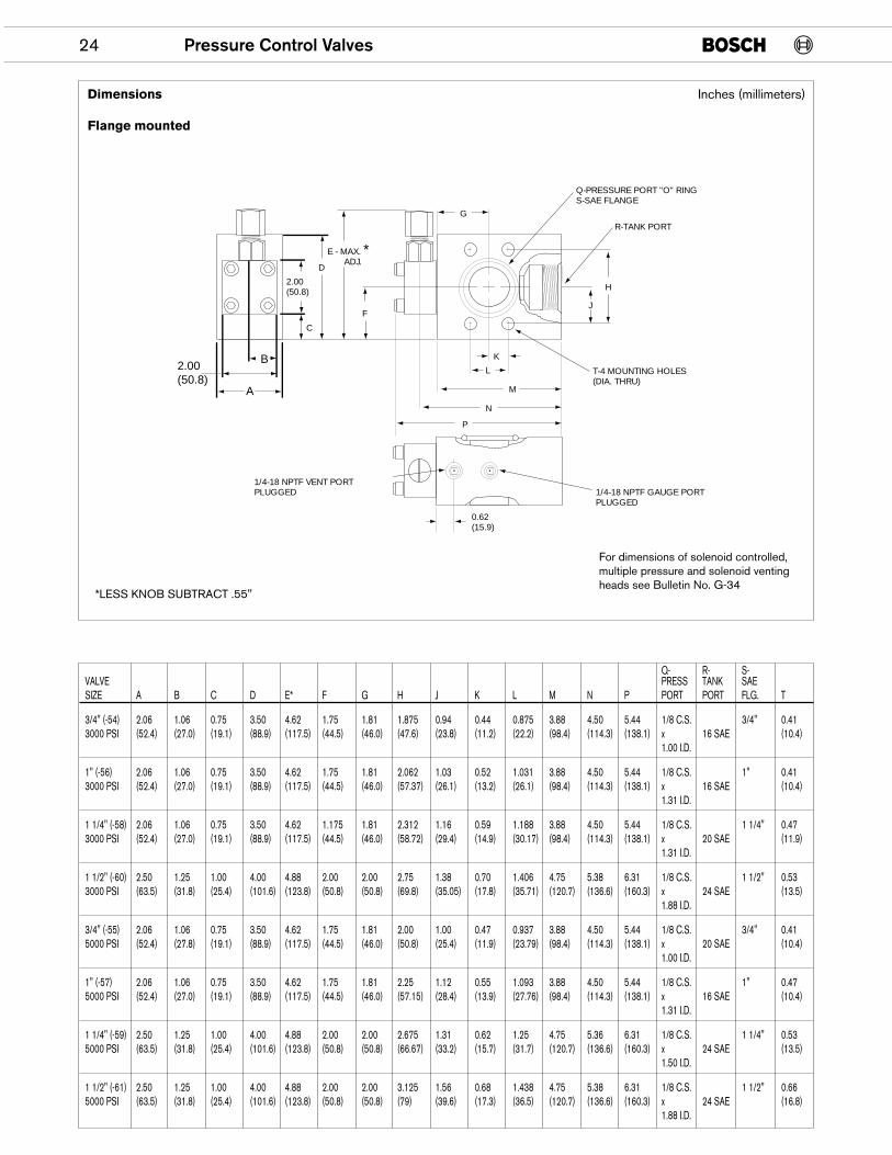
Q- R- S-VALVE PRESS TANK SAESIZE A B C D E* F G H J K L M N P PORT PORT FLG. T
3/4" (-54) 2.06 1.06 0.75 3.50 4.62 1.75 1.81 1.875 0.94 0.44 0.875 3.88 4.50 5.44 1/8 C.S. 3/4" 0.413000 PSI (52.4) (27.0) (19.1) (88.9) (117.5) (44.5) (46.0) (47.6) (23.8) (11.2) (22.2) (98.4) (114.3) (138.1) x 16 SAE (10.4)
1.00 I.D.
1" (-56) 2.06 1.06 0.75 3.50 4.62 1.75 1.81 2.062 1.03 0.52 1.031 3.88 4.50 5.44 1/8 C.S. 1" 0.413000 PSI (52.4) (27.0) (19.1) (88.9) (117.5) (44.5) (46.0) (57.37) (26.1) (13.2) (26.1) (98.4) (114.3) (138.1) x 16 SAE (10.4)
1.31 I.D.
1 1/4" (-58) 2.06 1.06 0.75 3.50 4.62 1.175 1.81 2.312 1.16 0.59 1.188 3.88 4.50 5.44 1/8 C.S. 1 1/4" 0.473000 PSI (52.4) (27.0) (19.1) (88.9) (117.5) (44.5) (46.0) (58.72) (29.4) (14.9) (30.17) (98.4) (114.3) (138.1) x 20 SAE (11.9)
1.31 I.D.
1 1/2" (-60) 2.50 1.25 1.00 4.00 4.88 2.00 2.00 2.75 1.38 0.70 1.406 4.75 5.38 6.31 1/8 C.S. 1 1/2" 0.533000 PSI (63.5) (31.8) (25.4) (101.6) (123.8) (50.8) (50.8) (69.8) (35.05) (17.8) (35.71) (120.7) (136.6) (160.3) x 24 SAE (13.5)
1.88 I.D.
3/4" (-55) 2.06 1.06 0.75 3.50 4.62 1.75 1.81 2.00 1.00 0.47 0.937 3.88 4.50 5.44 1/8 C.S. 3/4" 0.415000 PSI (52.4) (27.8) (19.1) (88.9) (117.5) (44.5) (46.0) (50.8) (25.4) (11.9) (23.79) (98.4) (114.3) (138.1) x 20 SAE (10.4)
1.00 I.D.
1" (-57) 2.06 1.06 0.75 3.50 4.62 1.75 1.81 2.25 1.12 0.55 1.093 3.88 4.50 5.44 1/8 C.S. 1" 0.475000 PSI (52.4) (27.0) (19.1) (88.9) (117.5) (44.5) (46.0) (57.15) (28.4) (13.9) (27.76) (98.4) (114.3) (138.1) x 16 SAE (10.4)
1.31 I.D.
1 1/4" (-59) 2.50 1.25 1.00 4.00 4.88 2.00 2.00 2.675 1.31 0.62 1.25 4.75 5.36 6.31 1/8 C.S. 1 1/4" 0.535000 PSI (63.5) (31.8) (25.4) (101.6) (123.8) (50.8) (50.8) (66.67) (33.2) (15.7) (31.7) (120.7) (136.6) (160.3) x 24 SAE (13.5)
1.50 I.D.
1 1/2" (-61) 2.50 1.25 1.00 4.00 4.88 2.00 2.00 3.125 1.56 0.68 1.438 4.75 5.38 6.31 1/8 C.S. 1 1/2" 0.665000 PSI (63.5) (31.8) (25.4) (101.6) (123.8) (50.8) (50.8) (79) (39.6) (17.3) (36.5) (120.7) (136.6) (160.3) x 24 SAE (16.8)
1.88 I.D.
24 Pressure Control Valves
*LESS KNOB SUBTRACT .55"
F
H
J
G
K
L
M
N
P
E - MAX. *ADJ.
Q-PRESSURE PORT "O" RINGS-SAE FLANGE
R-TANK PORT
T-4 MOUNTING HOLES(DIA. THRU)
1/4-18 NPTF VENT PORTPLUGGED 1/4-18 NPTF GAUGE PORT
PLUGGED
0.62(15.9)
2.00 (50.8)
2.00(50.8)
A
B
D
C
For dimensions of solenoid controlled,multiple pressure and solenoid ventingheads see Bulletin No. G-34
Inches (millimeters)Dimensions
Flange mounted
Pressure Control Valves 25
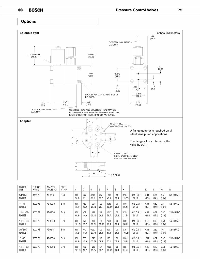
FLANGE FLANGE ADAPTER BOLTSIZE RATING MODEL NO. KIT NO. A C D E F G H J K L M N
3/4" (-54) 3000 PSI AD-75-3 B-53 3.00 0.44 0.875 0.94 1.875 1.00 0.75 0.12 C.S. x 0.41 0.59 0.41 3/8-16 UNCFLANGE (76.2) (11.1) (22.2) (23.7) (47.6) (25.4) (19.05) 1.00 I.D. (10.4) (14.9) (10.4)
1" (-56) 3000 PSI AD-100-3 B-53 3.00 0.52 1.031 1.03 2.062 1.00 1.00 0.12 C.S x 0.41 0.59 0.41 3/8-16 UNCFLANGE (76.2) (13.2) (26.18) (26.1) (52.37) (25.4) (25.4) 1.31 I.D. (10.4) (14.9) (10.4)
1 1/4" (-58) 3000 PSI AD-125-3 B-16 3.50 0.59 1.188 1.16 2.312 1.00 1.25 0.12 C.S. x 0.49 0.69 0.47 7/16-14 UNCFLANGE (88.9) (14.9) (30.14) (29.4) (58.7) (25.4) (31.7) 1.50 I.D. (11.9) (17.5) (11.9)
1 1/2" (-60) 3000 PSI AD-150-3 B-73 4.00 0.70 1.406 1.38 2.750 1.00 1.50 0.12 C.S. x 0.53 0.78 0.53 1/2-16 UNCFLANGE (101.6) (17.7) (35.71) (35.08) (69.8) (25.4) (38.1) 1.88 I.D. (13.4) (19.8) (13.4)
3/4" (-55) 6000 PSI AD-75-6 B-53 3.00 0.47 0.937 1.00 2.00 1.00 0.75 0.12 C.S. x 0.41 .059 .041 3/8-16 UNCFLANGE (76.2) (11.9) (23.79) (25.4) (50.8) (25.4) (19.05) 1.00 I.D. (10.4) (14.9) (10.4)
1" (-57) 6000 PSI AD-100-6 B-16 3.50 .055 1.093 1.12 2.25 1.00 1.00 0.12 C.S. x .047 0.69 0.47 7/16-14 UNCFLANGE (88.9) (13.9) (27.76) (28.4) (57.1) (25.4) (25.4) 1.31 I.D. (11.9) (17.9) (11.9)
1 1/4" (-59) 6000 PSI AD-125--6 B-73 4.00 0.62 1.250 1.31 2.625 1.00 1.25 0.12 C.S. x 0.53 0.78 0.53 1/2-13 UNCFLANGE (101.6) (15.2) (31.75) (33.2) (66.67) (25.4) (31.7) 1.50 I.D. (13.4) (19.8) (13.4)
2.00(50.8)
1.86 MAX(47.2)
2.00 APPROX.(50.8)
.31(7.9)
2.47(62.7)
.53(13.5)
SOCKET HD. CAP SCREW 5/16-184-PLACES
CONTROL MOUNTINGDATUM V
CONTROL HEAD AND SOLENOID HEAD MAY BEROTATED IN 90º INCREMENTS INDEPENDENTLY OF EACH OTHER FOR MOUNTING CONVENIENCE.
.92(23.4)
.81(20.6)
1.375(34.9)
.313(8.0)
.687(17.5)
1.375(34.9)
.19(4.8)
1.84(46.8)
CONTROL MOUNTINGDATUM H
F
F
E
E
C
CD
D
N-TAP THRU,4-MOUNTING HOLES
K-DRILL THRUL-DIA. C'BORE x M DEEP4-MOUNTING HOLEDS
G
A J-O-RINGH
Solenoid vent
Adapter
Inches (millimeters)
A flange adaptor is required on allsilent vane pump applications.
The flange allows rotation of thevalve by 90°.
Options
26 Pressure Control Valves
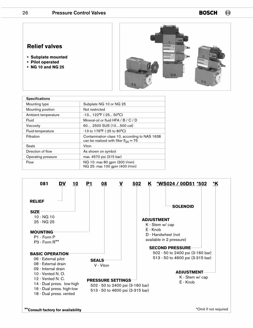
Relief valves
• Subplate mounted• Pilot operated• NG 10 and NG 25
SpecificationsMounting type Subplate NG 10 or NG 25Mounting position Not restrictedAmbient temperature -13... 122°F (-25... 50°C)Fluid Mineral-oil or fluid HFA / B / C / DViscosity 60… 2500 SUS (10…500 cst)Fluid-temperature -13 to 176°F (-25 to 80°C)Filtration Contamination class 10, according to NAS 1638
can be realized with filter ß25 = 75Seals VitonDirection of flow As shown on symbolOperating pressure max. 4570 psi (315 bar)Flow NG 10: max 80 gpm (300 l/min)
NG 25: max 100 gpm (400 l/min)
RELIEF
MOUNTINGP1 - Form PP3 - Form R**
**Consult factory for availability
SIZE10 - NG 1025 - NG 25
BASIC OPERATION06 - External pilot08 - External drain09 - Internal drain10 - Vented N. O.12 - Vented N. C.14 - Dual press. low-high16 - Dual press. high-low18 - Dual press. vented
PRESSURE SETTINGS502 - 50 to 2400 psi (3-160 bar)513 - 50 to 4600 psi (3-315 bar)
ADJUSTMENTK - Stem w/ capE - KnobD - Handwheel (notavailable in 2 pressure)
ADJUSTMENTK - Stem w/ capE - Knob
SECOND PRESSURE502 - 50 to 2400 psi (3-160 bar)513 - 50 to 4600 psi (3-315 bar)
SOLENOID
SEALSV - Viton
081 DV 10 P1 08 V 502 K *WS024 / 00D51 *502 *K
*Omit if not required
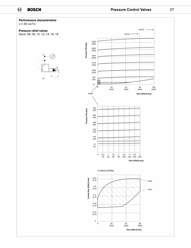
Pressure Control Valves 27
4350(300)
3625(250)
2900(200)
2175(150)
1450(100)
725(50)
0
435(30)
Detail
363(25)
290(20)
218(15)
145(10)
0.66(2.5)
.53(2.0)
0.26(1.0)
0
0.4(1.5)
0.13(0.5)
0 0.5(2)
1(4)
1.5(6)
2(8)
2.5(10)
3(12)
3.5(14)
4(16)
0 26(100)
53(200)
80(300)
105(400)
NG10
NG25
Control oil flow
0 26(100)
53(200)
80(300)
Pmax
Pmin
Pre
ssur
e P
SI (
bar)
Flow GPM (l/min)
Pre
ssur
e P
SI (
bar)
Flow GPM (l/min)
73(5)
Con
trol
flo
w G
PM
(l/
min
)
Flow GPM (l/min)
A
BX Y
Performance characteristicsν = 35 mm2/s
Pressure relief valvesSymb. 08, 09, 10, 12, 14, 16, 18
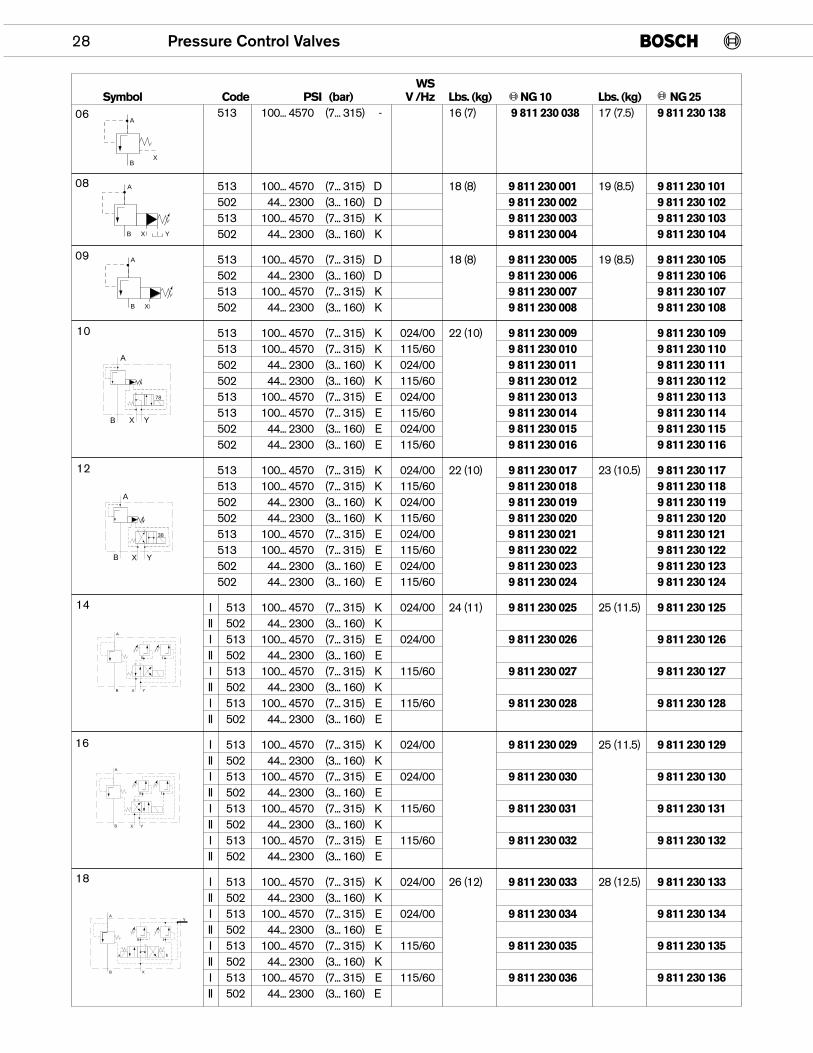
WSSymbol Code PSI (bar) V /Hz Lbs. (kg) NG 10 Lbs. (kg) NG 25
513 100... 4570 (7... 315) - 16 (7) 9 811 230 038 17 (7.5) 9 811 230 138
513 100... 4570 (7... 315) D 18 (8) 9 811 230 001 19 (8.5) 9 811 230 101502 44... 2300 (3... 160) D 9 811 230 002 9 811 230 102513 100... 4570 (7... 315) K 9 811 230 003 9 811 230 103502 44... 2300 (3... 160) K 9 811 230 004 9 811 230 104
513 100... 4570 (7... 315) D 18 (8) 9 811 230 005 19 (8.5) 9 811 230 105502 44... 2300 (3... 160) D 9 811 230 006 9 811 230 106513 100... 4570 (7... 315) K 9 811 230 007 9 811 230 107502 44... 2300 (3... 160) K 9 811 230 008 9 811 230 108
513 100... 4570 (7... 315) K 024/00 22 (10) 9 811 230 009 9 811 230 109513 100... 4570 (7... 315) K 115/60 9 811 230 010 9 811 230 110502 44... 2300 (3... 160) K 024/00 9 811 230 011 9 811 230 111502 44... 2300 (3... 160) K 115/60 9 811 230 012 9 811 230 112513 100... 4570 (7... 315) E 024/00 9 811 230 013 9 811 230 113513 100... 4570 (7... 315) E 115/60 9 811 230 014 9 811 230 114502 44... 2300 (3... 160) E 024/00 9 811 230 015 9 811 230 115502 44... 2300 (3... 160) E 115/60 9 811 230 016 9 811 230 116
513 100... 4570 (7... 315) K 024/00 22 (10) 9 811 230 017 23 (10.5) 9 811 230 117513 100... 4570 (7... 315) K 115/60 9 811 230 018 9 811 230 118502 44... 2300 (3... 160) K 024/00 9 811 230 019 9 811 230 119502 44... 2300 (3... 160) K 115/60 9 811 230 020 9 811 230 120513 100... 4570 (7... 315) E 024/00 9 811 230 021 9 811 230 121513 100... 4570 (7... 315) E 115/60 9 811 230 022 9 811 230 122502 44... 2300 (3... 160) E 024/00 9 811 230 023 9 811 230 123502 44... 2300 (3... 160) E 115/60 9 811 230 024 9 811 230 124
I 513 100... 4570 (7... 315) K 024/00 24 (11) 9 811 230 025 25 (11.5) 9 811 230 125II 502 44... 2300 (3... 160) KI 513 100... 4570 (7... 315) E 024/00 9 811 230 026 9 811 230 126II 502 44... 2300 (3... 160) EI 513 100... 4570 (7... 315) K 115/60 9 811 230 027 9 811 230 127II 502 44... 2300 (3... 160) KI 513 100... 4570 (7... 315) E 115/60 9 811 230 028 9 811 230 128II 502 44... 2300 (3... 160) E
I 513 100... 4570 (7... 315) K 024/00 9 811 230 029 25 (11.5) 9 811 230 129II 502 44... 2300 (3... 160) KI 513 100... 4570 (7... 315) E 024/00 9 811 230 030 9 811 230 130II 502 44... 2300 (3... 160) EI 513 100... 4570 (7... 315) K 115/60 9 811 230 031 9 811 230 131II 502 44... 2300 (3... 160) KI 513 100... 4570 (7... 315) E 115/60 9 811 230 032 9 811 230 132II 502 44... 2300 (3... 160) E
I 513 100... 4570 (7... 315) K 024/00 26 (12) 9 811 230 033 28 (12.5) 9 811 230 133II 502 44... 2300 (3... 160) KI 513 100... 4570 (7... 315) E 024/00 9 811 230 034 9 811 230 134II 502 44... 2300 (3... 160) EI 513 100... 4570 (7... 315) K 115/60 9 811 230 035 9 811 230 135II 502 44... 2300 (3... 160) KI 513 100... 4570 (7... 315) E 115/60 9 811 230 036 9 811 230 136II 502 44... 2300 (3... 160) E
28 Pressure Control Valves
A
BX
A
B X Y
A
B X
XB Y
A
78
XB Y
A
38
A
B X Y
III
A
B X Y
III
A
B X
Y
III
ba
06
08
09
10
12
14
16
18
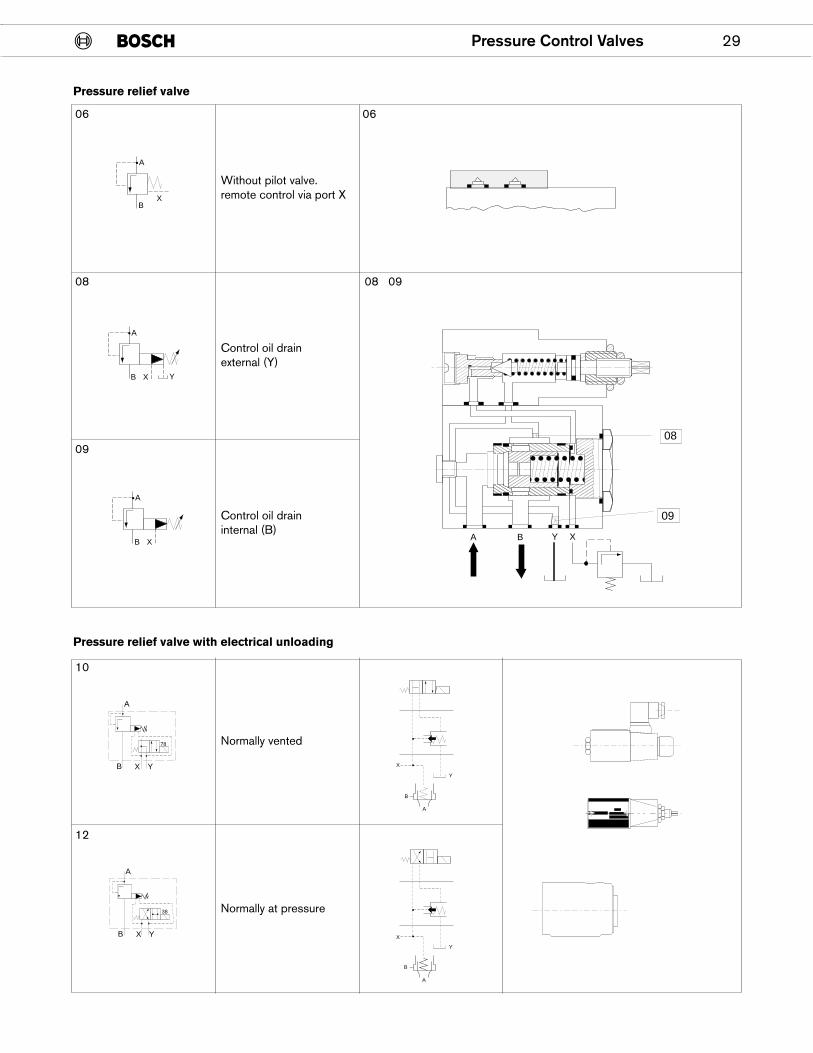
Pressure Control Valves 29
Pressure relief valve with electrical unloading
Pressure relief valve
A
BX
Y
A
B X
A
B X
Without pilot valve.remote control via port X
Control oil drainexternal (Y)
Control oil draininternal (B)
06 06
08 0908
XB Y
A
78
XB Y
A
38
Normally vented
Normally at pressure
10
12
09
����������������
A B Y X
08
09
���
Y
X
B
A
Y
X
B
A
30 Pressure Control Valves
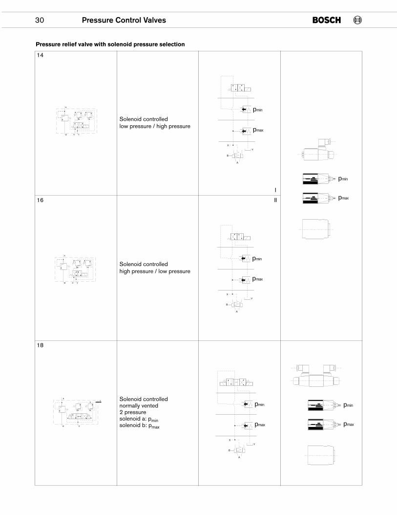
Pressure relief valve with solenoid pressure selection
Solenoid controlledlow pressure / high pressure
Solenoid controlledhigh pressure / low pressure
Solenoid controllednormally vented2 pressuresolenoid a: pminsolenoid b: pmax
A
B X Y
III
A
B X Y
III
A
B X
Y
III
ba
pmax
pmin
X
Y
B
A
pmax
pmin
pmax
pmin
X
Y
B
A
pmax
pmin
pmax
pmin
X
Y
B
A
16
18
I
II
14
Pressure Control Valves 31
3.54
(90
)2.
63 (
66.7
)
1.31
(33.
3)
ø 0.24 (6)
1.69 (43)
3.19 (81)M8
18 x 2.52 x
10 x 2
A
BX
X
B
A
3.82
(97
)
2.68
(68
)0.
16 (4
)
3.35
(85
)
4.21 (107)
4.53 (115)
ø 0.41(10.5)
4.02
(10
2)3.
13 (
79.4
)
1.56
(39
.7)
ø 0.24 (6)
2.37 (50.3)
3.53 (89.7)M8
28 x 32 x
10 x 2
3.82
(97
)
3.35
(85
)
4.45 (113)
4.76 (121)
ø10.5
X
Y
A B
X
Y
A B
2.68
(68
)
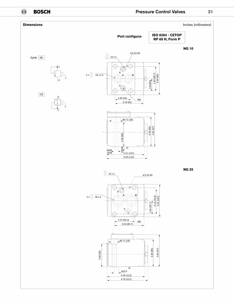
Symb. 06
33
ø0.71 (18)
ø0.71 (18)
Dimensions
Port configura- ISO 6264 - CETOPRP 69 H, Form P
NG 10
NG 25
Inches (millimeters)
32 Pressure Control Valves
��
4.53 (115)
ø0.41 (10.5)
4.21 (107)
4.53 (115)
3.19 (81)
ø 0.71 (18)0.3 (75)
17
max. 30
0.32
(8.
25)
0.16
(4)
5.28
(13
4)
1.93
(49
) ��
ø2.5
2 (6
4)
max 40
D
E + F
H
2.95 (75)0.79(20)
ø1.7
3 (4
4)
ø0.24 (6)
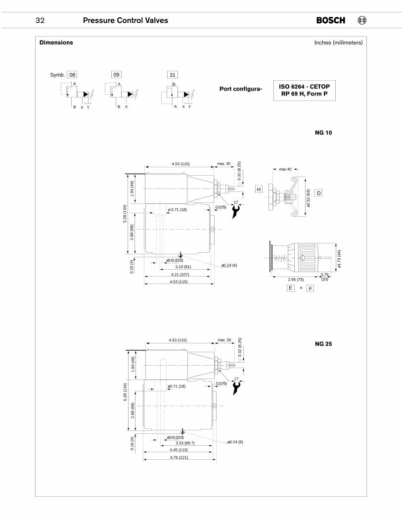
Symb. 08
B
A
X Y
09
B
A
X
31
B
A X Y
4.53 (115)
ø0.41 (10.5)
4.45 (113)
4.76 (121)
3.53 (89.7)
ø0.71 (18) 0.3 (75)
17
max. 30
0.32
(8.
25)
0.16
(4)
5.28
(13
4)
2.68
(68
)1.
93 (
49)
ø0.24 (6)
2.68
(68
)
Dimensions
NG 10
NG 25
Port configura- ISO 6264 - CETOPRP 69 H, Form P
Inches (millimeters)
Pressure Control Valves 33
4.53 (115)
Ø0.41 (10.5)
4.21 (107)
4.53 (115)
3.19 (81)
0.3(7.5)
17
max. 1.18(30)
0.32
(8.
25
0.16 (4)
3.35
(85
)
2.68
(69
)1.
83 (
49)
Ø0.24 (6)
5.63 (143.1)
0.5
(12)
8.35
(21
2)
X
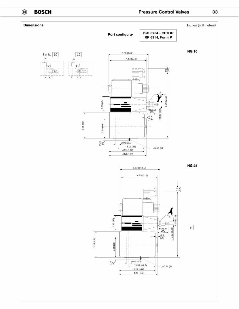
10
B Y
12
A
XB Y
A
4.53 (115)
Ø0.41 (10.5)
4.45 (113)
4.26 (121)
3.53 (89.7)
0.3(75)
17
0.32
(8.
25)
0.16 (4)
3.35
(85
)
2.68
(68
)1.
93 (
49)
Ø0.24 (6)
5.63 (143.1)
0.5
(12)
8.35
(21
2)
H
Symb.
x x x x78 38
max 1.38(35)
Dimensions
Port configura- ISO 6264 - CETOPRP 69 H, Form P
NG 10
NG 25
Inches (millimeters)
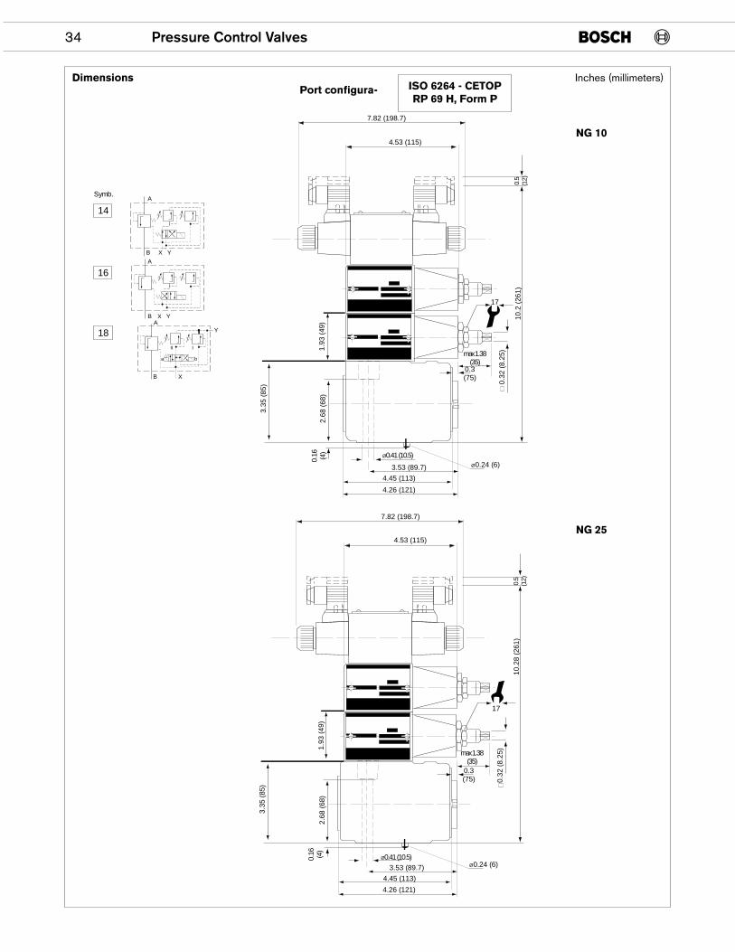
34 Pressure Control Valves
4.53 (115)
17
7.82 (198.7)
0.5
(12)
10.2
(26
1)
14
16
18
XB
XB
A
A
Y
YA
XB Y
4.53 (115)
17
7.82 (198.7)0.
5(1
2)10
.28
(261
)
Symb.
III
a b
Ø0.41 (10.5)
4.45 (113)
4.26 (121)
3.53 (89.7)
0.3(75)
0.32
(8.
25)
0.16 (4)
3.35
(85
)
2.68
(68
)1.
93 (
49)
Ø0.24 (6)
max 1.38(35)
Ø0.41 (10.5)
4.45 (113)
4.26 (121)
3.53 (89.7)
0.3(75) 0.
32 (
8.25
)
0.16 (4)
3.35
(85
)
2.68
(68
)1.
93 (
49)
Ø0.24 (6)
max 1.38(35)
DimensionsPort configura- ISO 6264 - CETOP
RP 69 H, Form P
NG 10
NG 25
Inches (millimeters)
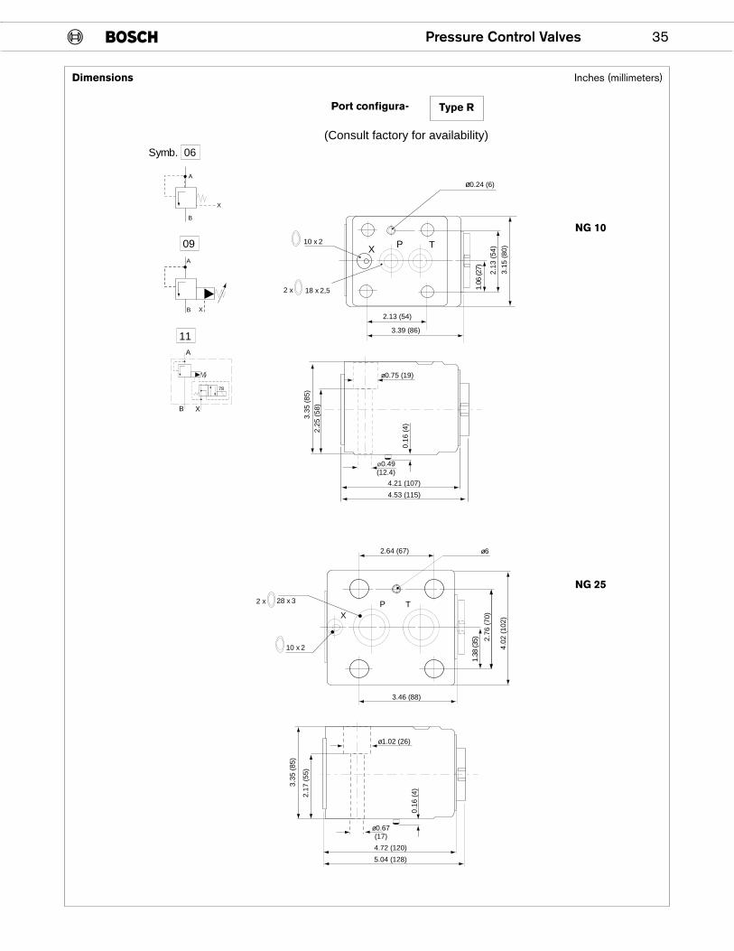
Pressure Control Valves 35
3.15
(80
)
2.13
(54
)
1.06
(27)
ø0.24 (6)
2.13 (54)
3.39 (86)
18 x 2,52 x
10 x 2
A
B X
X
B
A
4.21 (107)
3.35
(85
)2.
25 (
58)
0.16
(4)
4.53 (115)
Ø0.49(12.4)
ø0.75 (19)
4.02
(10
2)
2.76
(70
)
1.38
(35)
ø6
3.46 (88)
28 x 32 x
10 x 2
2.64 (67)
4.72 (120)
5.04 (128)
ø0.67(17)
ø1.02 (26)
2.17
(55
)
3.35
(85
)
0.16
(4)
Symb. 06
09
11
X TP
PX
T
XB
A
78
Dimensions
Port configura- Type R
NG 10
NG 25
Inches (millimeters)
(Consult factory for availability)
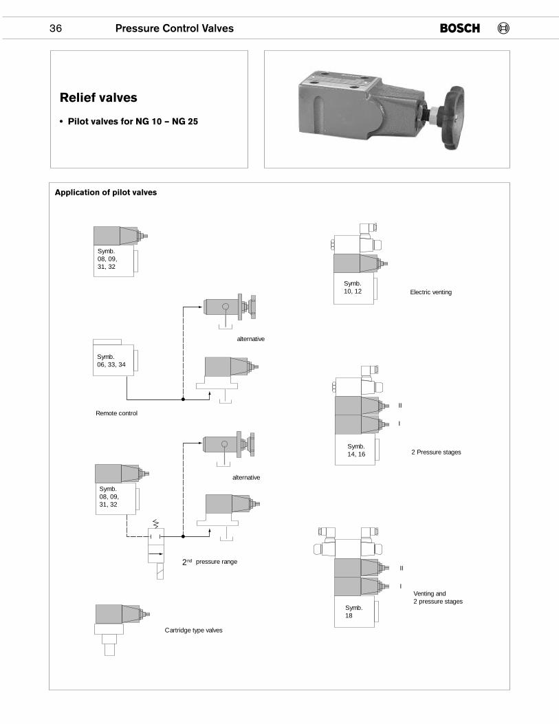
36 Pressure Control Valves
Relief valves
• Pilot valves for NG 10 – NG 25
Symb.08, 09,31, 32
Symb.08, 09,31, 32
Symb.10, 12
Symb.14, 16
Symb.18
Symb.06, 33, 34
alternative
alternative
pressure range2nd
Venting and2 pressure stages
Cartridge type valves
Remote control
2 Pressure stages
II
I
II
I
Electric venting
Application of pilot valves
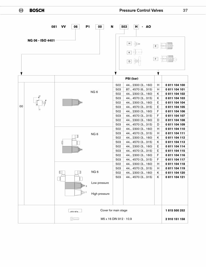
Pressure Control Valves 37
502 44... 2300 (3... 160) H 0 811 104 100503 87... 4570 (6... 315) H 0 811 104 101502 44... 2300 (3... 160) K 0 811 104 102503 44... 4570 (3... 315) K 0 811 104 103502 44... 2300 (3... 160) E 0 811 104 104503 44... 4570 (3... 315) E 0 811 104 105502 44... 2300 (3... 160) F 0 811 104 106503 44... 4570 (3... 315) F 0 811 104 107502 44... 2300 (3... 160) D 0 811 104 108503 44... 4570 (3... 315) D 0 811 104 109502 44... 2300 (3... 160) H 0 811 104 110503 44... 4570 (3... 315) H 0 811 104 111502 44... 2300 (3... 160) K 0 811 104 112503 44... 4570 (3... 315) K 0 811 104 113502 44... 2300 (3... 160) E 0 811 104 114503 44... 4570 (3... 315) E 0 811 104 115502 44... 2300 (3... 160) F 0 811 104 116503 44... 4570 (3... 315) F 0 811 104 117502 44... 2300 (3... 160) H 0 811 104 118503 44... 4570 (3... 315) H 0 811 104 119502 44... 2300 (3... 160) K 0 811 104 120503 44... 4570 (3... 315) K 0 811 104 121
1 815 500 252
2 910 151 158
PSI (bar)
P
T
II
I
00
NG 6
NG 6
Cover for main stage
M5 x 16 DIN 912 - 10.9
NG 6
Low pressure
High pressure
081 VV 06 P1 00 N 503 H - AO
HE
F
K
D
NG 06 - ISO 4401
38 Pressure Control Valves
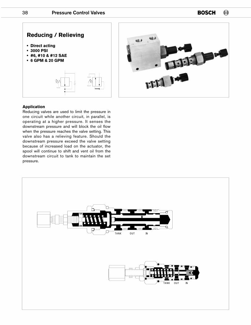
Reducing / Relieving
• Direct acting• 3000 PSI• #6, #10 & #12 SAE• 6 GPM & 20 GPM
TANK OUT IN
ApplicationReducing valves are used to limit the pressure inone circuit while another circuit, in parallel, isoperating at a higher pressure. It senses thedownstream pressure and will block the oil flowwhen the pressure reaches the valve setting. Thisvalve also has a relieving feature. Should thedownstream pressure exceed the valve settingbecause of increased load on the actuator, thespool will continue to shift and vent oil from thedownstream circuit to tank to maintain the setpressure.
TANK OUT IN
Pressure Control Valves 39
56
20 16 12 8 4 0FLOW RATE
4 8 1612 20
34 12 10
0 0
500
1000
2000
20
40
60
80
100
32 5 64
RE
GU
LATE
D P
RE
SS
UR
E
PS
I
BA
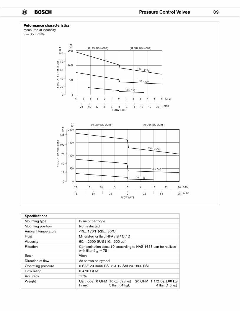
R (RELIEVING MODE) (REDUCING MODE)
GPM
L/min
20 - 150
50 - 500
100 - 1500
Peformance characteristicsmeasured at viscosityν = 35 mm2/s
SpecificationsMounting type Inline or cartridgeMounting position Not restrictedAmbient temperature -13... 176°F (-25... 80°C)Fluid Mineral-oil or fluid HFA / B / C / DViscosity 60… 2500 SUS (10…500 cst)Filtration Contamination class 10, according to NAS 1638 can be realized
with filter ß25 = 75Seals VitonDirection of flow As shown on symbolOperating pressure 6 SAE 20-3000 PSI, 8 & 12 SAI 20-1500 PSIFlow rating 6 & 20 GPMAccuracy ±5%Weight Cartridge: 6 GPM 10 oz. (.28 kg); 20 GPM 1 1/2 lbs. (.68 kg)
Inline: 3 lbs. (.4 kg); 4 lbs. (1.8 kg)
75
20 15 10 5 5 10 15 20
0
RE
GU
LATE
D P
RE
SS
UR
E
PS
I
BA
R
0
500
1000
1500
2000
25
50
75
100
125
50 25 0
0
FLOW RATE
(RELIEVING MODE) (REDUCING MODE)
25 50 75
GPM
L/min
20 - 150
50 - 500
100 - 1500
1.16(29.4)
0.873 (22.1)0.871 (22.1)
0.44(11.1)
1.00(25.4)
0.811 (20.5)0.809 (20.5)
1.44(36.6)
0.91(23.1)
3.22 MAX.(81.7)
1.60(40.6)
2.20(55.9)
0.936 (23.7)0.934 (23.7)
*2.69(68.3) MAX. LESS KNOB
MAX. PRESSURE STOP SET AT FACTORY
1-1/4 HEX1-1/16-12 UNF 2A THD.
0.69(17.5)
1.280(32.5)
1.850(32.5)
2.350(59.7)
CAVITY
30°30°30°
A
A
.002
0.9365 (23.78)0.9385 (23.83)
0.972 (24.7)0.990 (25.1)
A .002
0.8745 (22.21)0.8765 (22.26)
A .002
0.8115 (20.61)0.8135 (20.66)
0.25(59.7)
.005 (0.127)
.010 (0.254)RADIUS
45° OR RADIUS
COUNTERBORE #12 SAE TAP1-1/16-12 UNF 2B X .53 DEEP
40 Pressure Control Valves
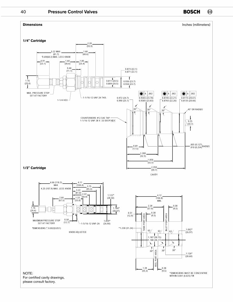
Dimensions
1/4" Cartridge
1/2" Cartridge
NOTE:For certified cavity drawings,please consult factory.
Inches (millimeters)
4.66 (118.3)MAX
4.25 (107.9) MAX. LESS KNOB
4.11(104.4) 3.75
(95.3)3.22(81.8) 2.22
(56.4)2.66(67.5)
1.33(33.8)
1.184*(30.07)
1.059*(26.90)
0.50(12.7)
*DIMENSIONS 0.002(0.051)
1.122*(28.50)
1.16(29.4)
+_
MAXIMUM PRESSURE STOPSET AT FACTORY 1-5/16-12 UNF-2A
KNOB ADJUSTED
1.39(35.3)
0.38(9.5)
* DIMENSIONS MUST BE CONCENTRICWITHIN 0.001 (0.025) TIR
1.126*(28.60)
1.062*(26.97)
0.38(9.5)
2.28(57.9)
0.38(9.5)
4.12(104.8)MIN.
0.51(12.9)
* 1.230 (31.24)
30°30°30°
63 63 63
1.187 (30.15)1.188 (30.17)
RE
G. P
OR
T A
RE
A
TAN
K P
OR
T A
RE
A
INLE
T P
OR
T A
RE
A
Pressure Control Valves 41
3.22* MAX.(81.7)
2.69*(68.3) MAX. LESS KNOB
1.14(28.9)
0.31(7.87) 0.31
(7.87)
1.16(29.4)
2.38(60.45)
2 - MOUNTING HOLES.343 (8.8) DIA. THRU
OUTLET PORT#6 SAE
1.00(25.4)
2.62(66.5)
0.25(6.35)
1.44(36.57)
5.84 MAX.(148.3)
1.718(43.6)
0.530(13.4)
1.00(25.4)
2.00(50.8)
3.00(76.2)
TWO PORTS#6 SAE
OUT
T IN
MAXIMUM PRESSURE STOPSET AT FACTORY
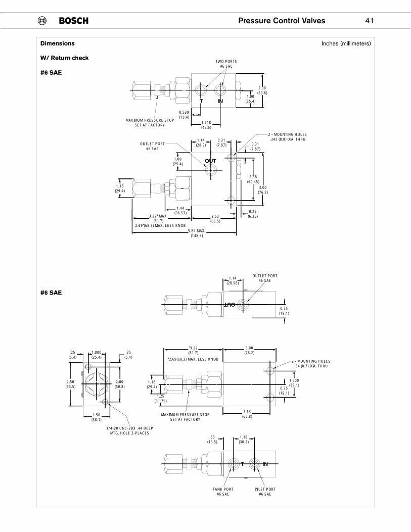
Dimensions
W/ Return check
#6 SAE
#6 SAE
Inches (millimeters)
OUT
1.000(25.4)
.25(6.4)
.25(6.4)
2.00(50.8)
*3.22(81.7)
*2.69(68.3) MAX. LESS KNOB
3.00(76.2)
1.50(38.1)
2.50(63.5)
1.25(31.75)
1.16(29.4)
1.500(38.1)
2 - MOUNTING HOLES.34 (8.7) DIA. THRU
0.75(19.1)
MAXIMUM PRESSURE STOPSET AT FACTORY
1/4-20 UNC-2BX .44 DEEPMTG. HOLE 2-PLACES
1.18(30.2)
.53(13.5)
1.14(28.96)
2.63(66.8)
0.75(19.1)
T IN
INLET PORT#6 SAE
OUTLET PORT#6 SAE
TANK PORT#6 SAE
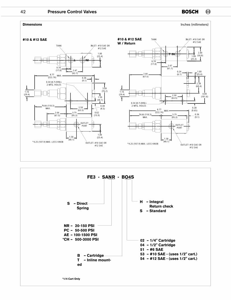
42 Pressure Control Valves
8.77(222.76)
0.70(17.8) 2.47
(62.7)
0.36(9.1)
INLET-
OUTLET-
OUTLETPORT
* 4.25 (107.9) MAX. LESS KNOB #10 SAE OR#12 SAE
#10 SAE OR#12 SAE
0.34 (8.7) DRILL2-MTG. HOLES
TANK
3.00(76.2)
1.50(38.1)
2.50(63.5)
1.58(40.1)
3.75(95.3)
2.66(67.5)
*4.66 (118.3)MAX.
1.16(29.4)
1.00(25.4)
1.00(25.4)
0.38(9.5)
0.62(15.9)
MAX.
T IN
Dimensions
#10 & #12 SAE #10 & #12 SAEW / Return
Inches (millimeters)
*NR – 20-150 PSI*PC – 50-500 PSI*AE – 100-1500 PSI*CH – 500-3000 PSI
*1/4 Cart Only
B – CartridgeT – Inline mount-ed
02 – 1/4" Cartridge04 – 1/2" Cartridge51 – #6 SAE53 – #10 SAE - (uses 1/2" cart.)54 – #12 SAE - (uses 1/2" cart.)
H – IntegralReturn check
S – Standard
S – DirectSpring
FE3 - SANR - BO4S
2.66(67.5)
0.70(17.8)
2.47(61.1)
0.24(6.1)
INLET-
OUTLET-
OUTLETPORT
* 4.25 (107.9) MAX. LESS KNOB #10 SAE OR#12 SAE
#10 SAE OR#12 SAE
0.34 (8.7) DRILL2-MTG. HOLES
TANK
4.00(101.6)
2.38(60.4)
2.50(63.5)
1.58(40.1)
3.75(95.3)
*4.66 (118.3)MAX.
8.77(222.76)
1.00(25.4)
1.16(29.4)
1.00(25.4)
2.00(50.8)
0.38(9.65)
0.36(9.1)
T IN
MAX.
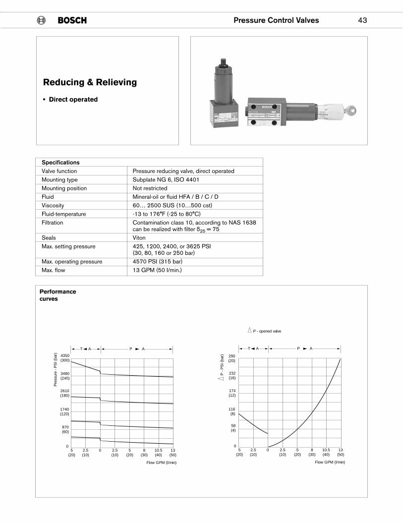
Pressure Control Valves 43
Reducing & Relieving
• Direct operated
SpecificationsValve function Pressure reducing valve, direct operatedMounting type Subplate NG 6, ISO 4401Mounting position Not restrictedFluid Mineral-oil or fluid HFA / B / C / DViscosity 60… 2500 SUS (10…500 cst)Fluid-temperature -13 to 176°F (-25 to 80°C)Filtration Contamination class 10, according to NAS 1638
can be realized with filter ß25 = 75Seals VitonMax. setting pressure 425, 1200, 2400, or 3625 PSI
(30, 80, 160 or 250 bar)Max. operating pressure 4570 PSI (315 bar)Max. flow 13 GPM (50 I/min.)
4350(300)
3480(240)
2610(180)
1740(120)
870(60)
05
(20)2.5(10)
0 2.5(10)
5(20)
8(30)
10.5(40)
13(50)
Flow GPM (l/min)
AT AP
290(20)
232(16)
174(12)
116(8)
58(4)
05
(20)2.5(10)
0 2.5(10)
5(20)
8(30)
10.5(40)
13(50)
Flow GPM (l/min)
P -
PS
I (ba
r)
AT AP
P - opened valve
Pre
ssur
e - P
SI (
bar)
Performancecurves
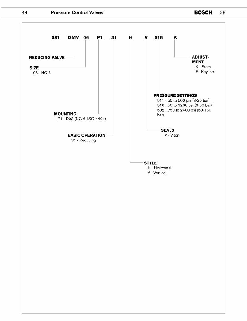
44 Pressure Control Valves
REDUCING VALVE
MOUNTINGP1 - D03 (NG 6, ISO 4401)
SIZE06 - NG 6
BASIC OPERATION31 - Reducing
PRESSURE SETTINGS511 - 50 to 500 psi (3-30 bar)516 - 50 to 1200 psi (3-80 bar)502 - 750 to 2400 psi (50-160bar)
STYLEH - HorizontalV - Vertical
ADJUST-MENT
K - StemF - Key lock
SEALSV - Viton
081 DMV 06 P1 31 H V 516 K
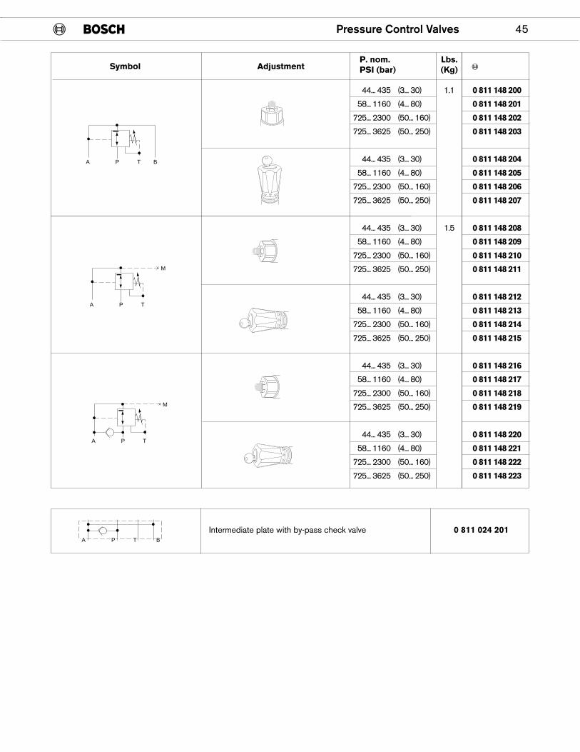
Pressure Control Valves 45
44... 435 (3... 30) 1.1 0 811 148 200
58... 1160 (4... 80) 0 811 148 201
725... 2300 (50... 160) 0 811 148 202
725... 3625 (50... 250) 0 811 148 203
44... 435 (3... 30) 0 811 148 204
58... 1160 (4... 80) 0 811 148 205
725... 2300 (50... 160) 0 811 148 206
725... 3625 (50... 250) 0 811 148 207
44... 435 (3... 30) 1.5 0 811 148 208
58... 1160 (4... 80) 0 811 148 209
725... 2300 (50... 160) 0 811 148 210
725... 3625 (50... 250) 0 811 148 211
44... 435 (3... 30) 0 811 148 212
58... 1160 (4... 80) 0 811 148 213
725... 2300 (50... 160) 0 811 148 214
725... 3625 (50... 250) 0 811 148 215
44... 435 (3... 30) 0 811 148 216
58... 1160 (4... 80) 0 811 148 217
725... 2300 (50... 160) 0 811 148 218
725... 3625 (50... 250) 0 811 148 219
44... 435 (3... 30) 0 811 148 220
58... 1160 (4... 80) 0 811 148 221
725... 2300 (50... 160) 0 811 148 222
725... 3625 (50... 250) 0 811 148 223
A P T B
A P T
M
A P T
M
Symbol AdjustmentP. nom.PSI (bar)
Lbs.(Kg)
Intermediate plate with by-pass check valve 0 811 024 201A P T B
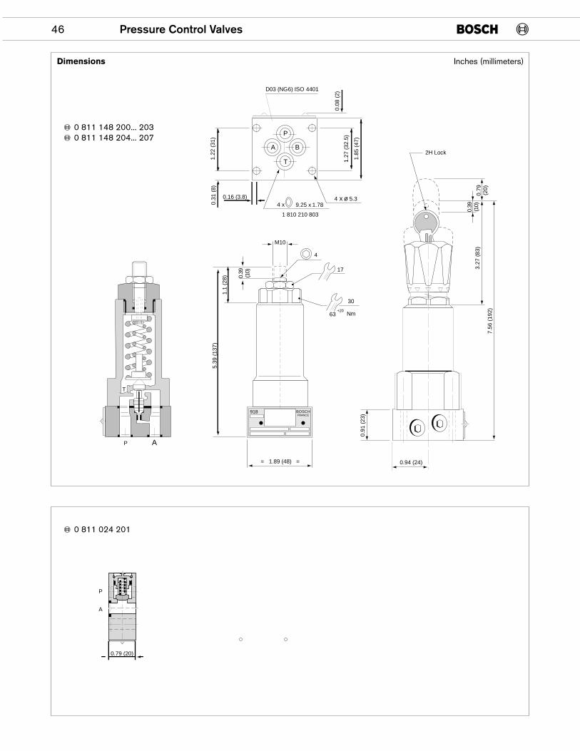
46 Pressure Control Valves
0.16 (3.8)
0.08
(2)
918 BOSCHFRANCE
M100.
39(1
0)
1.1
(28)
5.39
(13
7)
= 1.89 (48) =
4
17
30
0.94 (24)
63 Nm+20
0.39
(10)
0.79
(20)
3.27
(83
)
7.56
(19
2)
0.91
(23
)
2H Lock
P A
T
D03 (NG6) ISO 4401
4 x 9.25 x 1.78
1 810 210 803
4 x ø 5.3
A
P
T
B
1.22
(31
)0.
31 (
8)
1.27
(32
.5)
1.85
(47
)
P
A
0.79 (20)
Dimensions Inches (millimeters)
0 811 148 200... 2030 811 148 204... 207
0 811 024 201
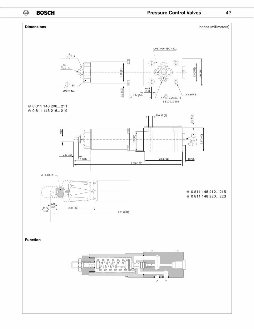
Pressure Control Valves 47
D03 (NG6) ISO 4401
0.2 (5)1.1 (28)
M10
1.26
(32
)
Ø 0.35 (9)
0.08
(2)
G 1/4
6
0.39(10)0.79
(10)3.27 (83)
9.21 (234)
2H LOCK
1.28
(32.
5))
1.57
(46
)
0.43(11)
1.34 (34)0.3
(7.5
)1.
22 (
31)
17
30
4
4 x 9.25 x 1.78
1 810 210 803
4 x ø 5.3
A
P
T
T
A P
1.57
(40
)
7.05 (179)
2.56 (65)
0.39 (10)
Inches (millimeters)
0 811 148 208... 2110 811 148 216... 219
0 811 148 212... 2150 811 148 220... 223
Dimensions
Function
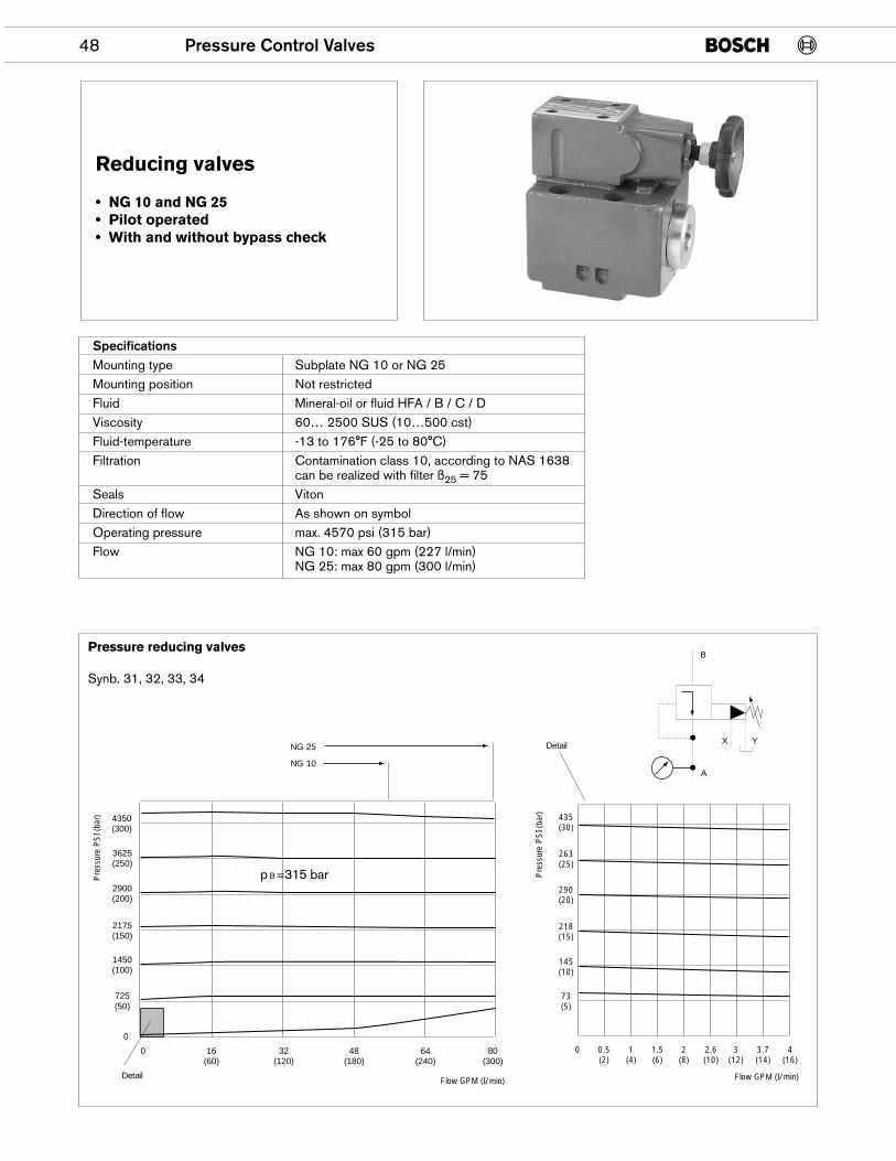
48 Pressure Control Valves
Reducing valves
• NG 10 and NG 25• Pilot operated• With and without bypass check
SpecificationsMounting type Subplate NG 10 or NG 25Mounting position Not restrictedFluid Mineral-oil or fluid HFA / B / C / DViscosity 60… 2500 SUS (10…500 cst)Fluid-temperature -13 to 176°F (-25 to 80°C)Filtration Contamination class 10, according to NAS 1638
can be realized with filter ß25 = 75Seals VitonDirection of flow As shown on symbolOperating pressure max. 4570 psi (315 bar)Flow NG 10: max 60 gpm (227 l/min)
NG 25: max 80 gpm (300 l/min)
4350(300)
3625(250)
2900(200)
2175(150)
1450(100)
725(50)
435(30)
263(25)
290(20)
218(15)
145(10)
73(5)
0
0 0 0.5(2)
1(4)
1.5(6)
2(8)
2.6(10)
3(12)
3.7(14)
4(16)
16(60)
32(120)
48(180)
64(240)
80(300)
NG 10
NG 25
Detail Flow GPM (I/min)
Pre
ssur
e P
SI (
bar)
Flow GPM (I/min)
Pre
ssur
e P
SI (
bar)
Detail
A
B
X Y
Pressure reducing valves
Synb. 31, 32, 33, 34
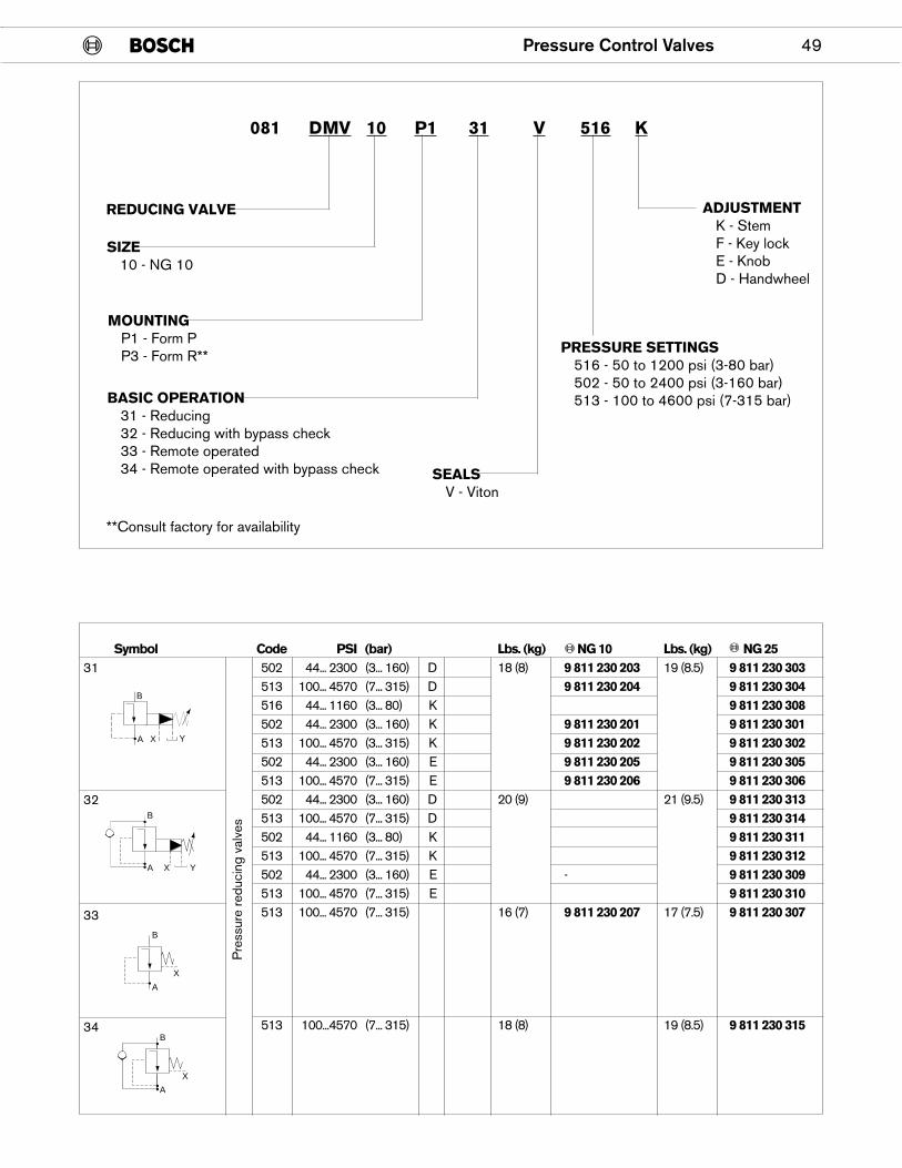
Pressure Control Valves 49
REDUCING VALVE
MOUNTINGP1 - Form PP3 - Form R**
SIZE10 - NG 10
BASIC OPERATION31 - Reducing32 - Reducing with bypass check33 - Remote operated34 - Remote operated with bypass check
PRESSURE SETTINGS516 - 50 to 1200 psi (3-80 bar)502 - 50 to 2400 psi (3-160 bar)513 - 100 to 4600 psi (7-315 bar)
ADJUSTMENTK - StemF - Key lockE - KnobD - Handwheel
SEALSV - Viton
081 DMV 10 P1 31 V 516 K
Symbol Code PSI (bar) Lbs. (kg) NG 10 Lbs. (kg) NG 25502 44... 2300 (3... 160) D 18 (8) 9 811 230 203 19 (8.5) 9 811 230 303513 100... 4570 (7... 315) D 9 811 230 204 9 811 230 304516 44... 1160 (3... 80) K 9 811 230 308502 44... 2300 (3... 160) K 9 811 230 201 9 811 230 301513 100... 4570 (3... 315) K 9 811 230 202 9 811 230 302502 44... 2300 (3... 160) E 9 811 230 205 9 811 230 305 513 100... 4570 (7... 315) E 9 811 230 206 9 811 230 306502 44... 2300 (3... 160) D 20 (9) 21 (9.5) 9 811 230 313513 100... 4570 (7... 315) D 9 811 230 314502 44... 1160 (3... 80) K 9 811 230 311513 100... 4570 (7... 315) K 9 811 230 312502 44... 2300 (3... 160) E - 9 811 230 309513 100... 4570 (7... 315) E 9 811 230 310513 100... 4570 (7... 315) 16 (7) 9 811 230 207 17 (7.5) 9 811 230 307
513 100...4570 (7... 315) 18 (8) 19 (8.5) 9 811 230 315
YA
B
X
B
A X Y
B
A
X
B
A
X
Pre
ssur
e re
duci
ng v
alve
s
31
32
33
34
**Consult factory for availability
50 Pressure Control Valves
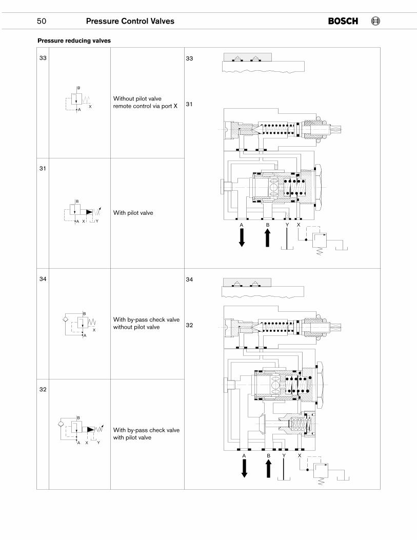
Pressure reducing valves
33
31
34
32
Without pilot valveremote control via port X
With pilot valve
With by-pass check valvewithout pilot valve
With by-pass check valvewith pilot valve
���������
A B Y X
��
�����������
������
���������
A B Y X
����������
A
B
X Y
A
B
X
YA
B
X
B
XA
33
31
34
32
Pressure Control Valves 51
4.53 (115)
Ø0.41 (10.5)
4.21 (107)
4.53 (115)
3.19 (31)
Ø0.71 (18) 0.3 (7.5)
17
max. 1.18(30)
0.32
(8.
25)
2.52
(64
)
0.16 (4)
3.46
(88
)
6.10
(15
5)
1.83
(49
)
4.53 (115)
Ø0.41 (10.5)
4.45 (113)
4.76 (121)
3.53 (89.7)
Ø0.71 (18) 0.3(7.5)
17
max. 1.18(30)
0.32
(8.
25)
2.64
(67
)
3.46
(88
)
6.22
(15
8)
1.93
(49
)
Ø0.41 (10.5)
4.21 (107)
4.53 (115)
3.19 (81)
Ø0.71 (18)
2.52
(64
) 4.17
(10
6) 4.65
(11
8)
Ø0.41 (10.5)
4.45 (113)
4.76 (121)
89,7
Ø0.71 (18)
2.64
(67
)3.46
(88
)
4.29
(10
9) 4.26
(12
1)
Symb. 32
B
AX Y
Symb. 34
B
A
X
0.16 (4)
3.46
(88
)
0.16 (4)
0.16 (4)
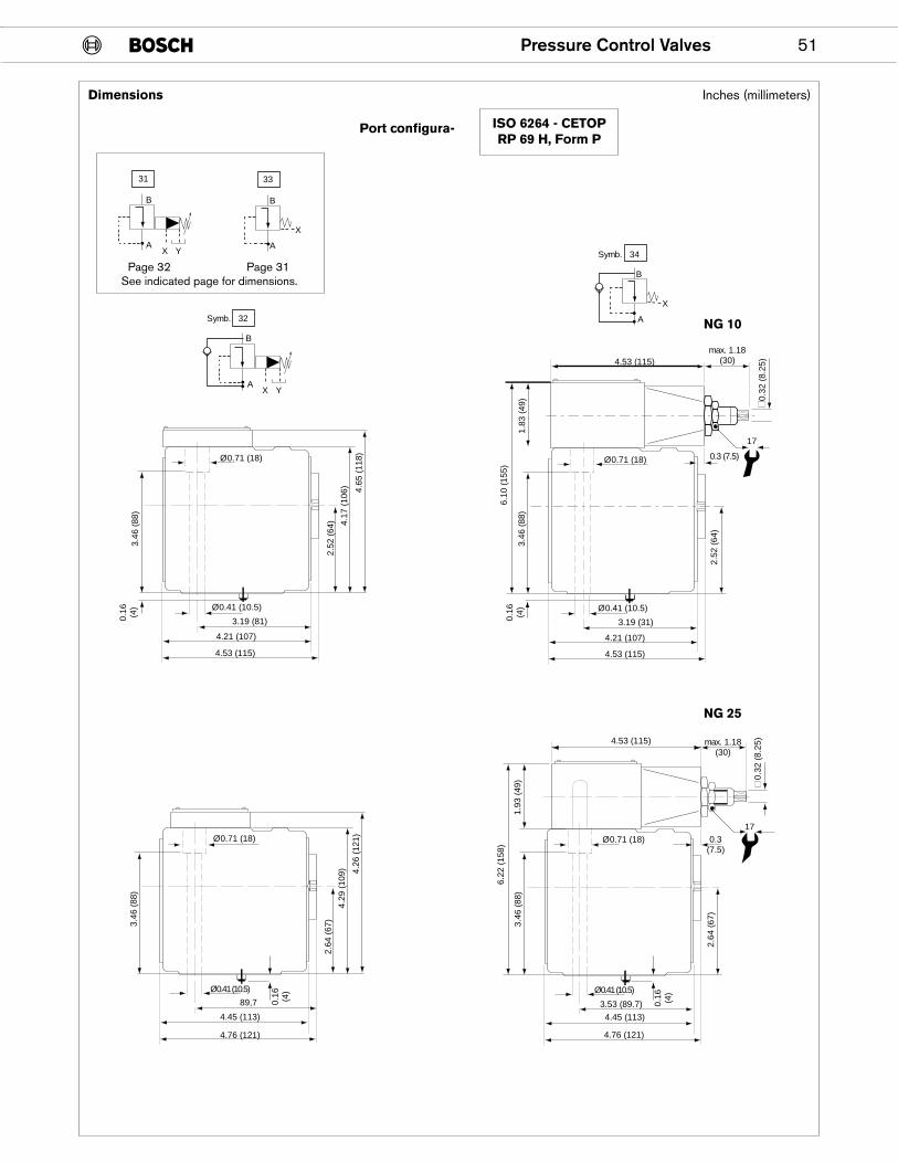
Dimensions
Port configura- ISO 6264 - CETOPRP 69 H, Form P
NG 10
NG 25
Inches (millimeters)
31
B
AX Y
33
B
A
X
Page 32 Page 31See indicated page for dimensions.
52 Pressure Control Valves
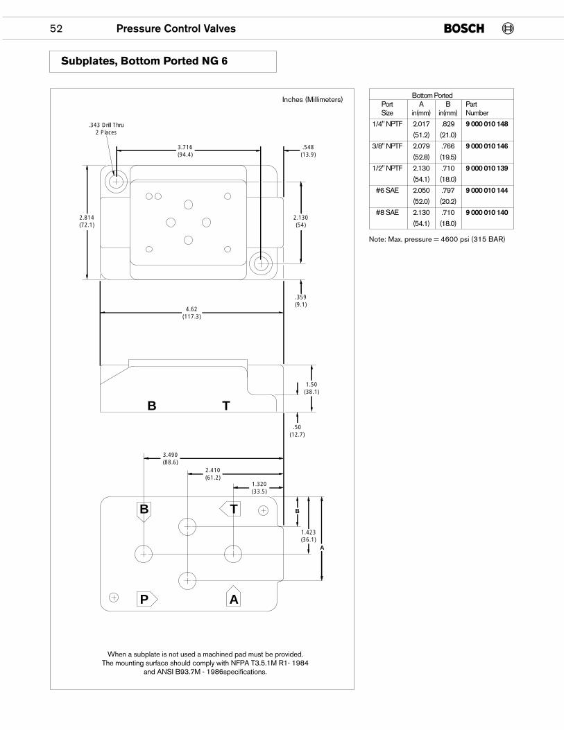
When a subplate is not used a machined pad must be provided.The mounting surface should comply with NFPA T3.5.1M R1- 1984
and ANSI B93.7M - 1986specifications.
Subplates, Bottom Ported NG 6
Inches (Millimeters)
3.716(94.4)
.343 Drill Thru2 Places
.548(13.9)
2.130(54)
.359(9.1)
1.50(38.1)
.50(12.7)
B
1.423(36.1)
A
2.814(72.1)
4.62(117.3)
1.320(33.5)
2.410(61.2)
3.490(88.6)
TB
TB
P A
Bottom PortedPort A B PartSize in(mm) in(mm) Number
1/4" NPTF 2.017 .829 9 000 010 148(51.2) (21.0)
3/8" NPTF 2.079 .766 9 000 010 146(52.8) (19.5)
1/2" NPTF 2.130 .710 9 000 010 139(54.1) (18.0)
#6 SAE 2.050 .797 9 000 010 144(52.0) (20.2)
#8 SAE 2.130 .710 9 000 010 140(54.1) (18.0)
Note: Max. pressure = 4600 psi (315 BAR)
Pressure Control Valves 53
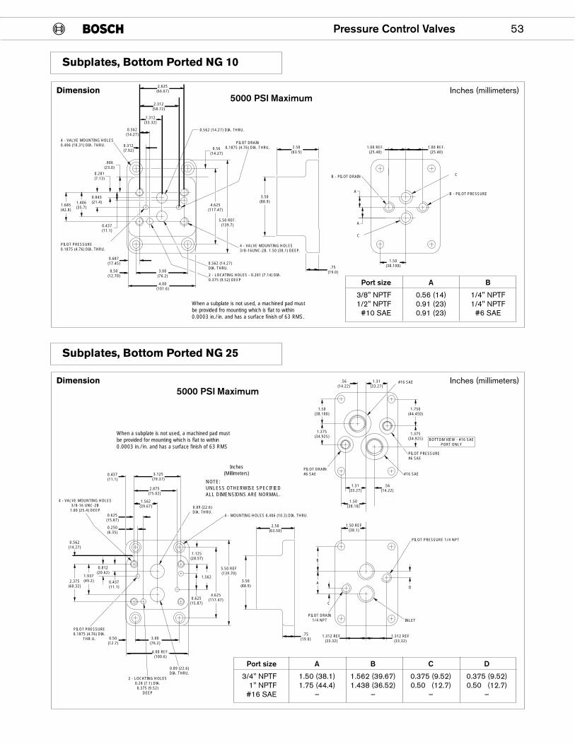
Subplates, Bottom Ported NG 10
2.625(66.67)
.906(23.0)
0.281(7.13)
0.437(11.1)
1.685(42.8)
4.00(101.6)
3.00(76.2)
2.312(58.72)
1.312(33.32)
0.312(7.92)
0.687(17.45)
0.50(12.70)
0.562(14.27)
4.625(117.47)
5.50 REF.(139.7)
0.56(14.27)
1.406(35.7)
0.843(21.4)
2.50(63.5)
1.50(38.100)
1.00 REF.(25.40)
1.00 REF.(25.40)
.75(19.0)
3.50(88.9)
4 - VALVE MOUNTING HOLES0.406 (10.31) DIA. THRU.
PILOT PRESSURE0.1875 (4.76) DIA. THRU.
0.562 (14.27)DIA. THRU.
4 - VALVE MOUNTING HOLES3/8-16UNC-2B. 1.50 (38.1) DEEP.
2 - LOCATING HOLES - 0.281 (7.14) DIA.0.375 (9.52) DEEP
PILOT DRAIN0.1875 (4.76) DIA. THRU.
0.562 (14.27) DIA. THRU.
A
A
C
C
B - PILOT PRESSURE
B - PILOT DRAIN
When a subplate is not used, a machined pad mustbe provided fro mounting which is flat to within0.0003 in./in. and has a surface finish of 63 RMS.
Subplates, Bottom Ported NG 25
2.375(60.32)
0.562(14.27)
1.937(49.2)
1.562
0.625(15.87)
0.89 (22.6)DIA. THRU.
PILOT PRESSURE0.1875 (4.76) DIA.
THR U.
2 - LOCATING HOLES0.28 (7.1) DIA.0.375 (9.52)
DEEP
1.125(28.57)
0.812(20.62)
0.437(11.1)
3.125(79.37)
4.00 REF.(100.6)
2.875(75.02)
1.562(39.67)
0.625(15.87)
0.437(11.1)
0.250(6.35)
3.50(88.9)
B
C
1.50(38.100)
1.750(44.450)
1.375(34.925)
BOTTOM VIEW - #16 SAEPORT ONLY
1.375(34.925)
AD
5.50 REF(139.70)
4.625(117.47)
2.50(63.50)
1.50 REF(38.1)
1.31(33.27)
.56(14.22)
1.50(38.10)
1.31(33.27)
.56(14.22)
#16 SAEPILOT DRAIN#6 SAE
PILOT PRESSURE#6 SAE
.75(19.0)
INLET
1.312 REF(33.32)
1.312 REF(33.32)
3.00(76.2)
0.50(12.7)
4 - VALVE MOUNTING HOLES3/8-16 UNC-2B
1.00 (25.4) DEEP0.89 (22.6)DIA. THRU.
4 - MOUNTING HOLES 0.406 (10.3) DIA. THRU.
When a subplate is not used, a machined pad mustbe provided for mounting which is flat to within0.0003 in./in. and has a surface finish of 63 RMS
Inches(Millimeters)
NOTE:UNLESS OTHERWISE SPECIFIEDALL DIMENSIONS ARE NORMAL.
#16 SAE
PILOT PRESSURE 1/4 NPT
PILOT DRAIN1/4 NPT
Inches (millimeters)Dimension
Port size A B
3/8" NPTF 0.56 (14) 1/4" NPTF1/2" NPTF 0.91 (23) 1/4" NPTF
#10 SAE 0.91 (23) #6 SAE
Port size A B C D
3/4" NPTF 1.50 (38.1) 1.562 (39.67) 0.375 (9.52) 0.375 (9.52)1" NPTF 1.75 (44.4) 1.438 (36.52) 0.50 (12.7) 0.50 (12.7)
#16 SAE — — — —
Inches (millimeters)Dimension5000 PSI Maximum
5000 PSI Maximum
54 Pressure Control Valves
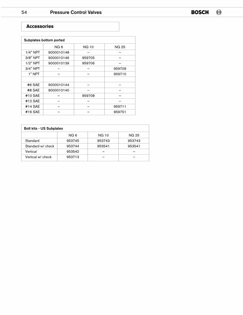
Accessories
Subplates bottom ported
NG 6 NG 10 NG 25
1/4" NPT 9000010148 — —
3/8" NPT 9000010146 959705 —
1/2" NPT 9000010139 959706 —
3/4" NPT — — 959709
1" NPT — — 959710
#6 SAE 9000010144 — —
#8 SAE 9000010140 — —
#10 SAE — 959708 —
#12 SAE — — —
#14 SAE — — 959711
#16 SAE — — 959751
Bolt kits - US Subplates
NG 6 NG 10 NG 25
Standard 953745 953743 953743
Standard w/ check 953744 953541 953541
Vertical 953542 — —
Vertical w/ check 953713 — —

ROBERT BOSCH FLUID POWER CORPORATIONP.O. BOX 2025RACINE, WISCONSIN 53401-2025 U.S.A.Phone (414)554-7100, Fax (414)554-7117
PRINTED IN U.S.A.
9 535 233 718HPUS AKY 007/20 US (3.96)