Embed Size (px)
Citation preview

IC.PD.P10.B5.02 / 520B4713
Technical brochure
Pressure controls,Type RT
Features y Simple design
y High accuracy
y High repeatability
RT Pressure Controls incorporate a pressure controlled, single-pole change over swich where the contact position depends on the pressure in the connection port and the set value.
The RT series consists of pressure controls, differential pressure controls and pressure controls for neutral zone regulation, all for general use within the industrial and marine segments. The series also covers safety pressure controls dedicated for steam boiler plants.
For installations in which operation is particularly critical from safety and economic points of view, the use of fail-safe pressure controls is recommended.
The use of gold-plated contacts is also recommended in such installations, provided operation involves only a few switching cycles or signal currents and voltages.
y Long operation life time
y Available with all major marine approvals
MAKING MODERN LIVING POSSIBLE
2
Technical brochure Pressure controls, type RT
IC.PD.P10.B5.02 / 520B4713
RT 1 RT 1ART 5ART 121
RT 1AL RT 5 RT 30AWRT 30ABRT 30ASRT 19WRT 19BRT 19S
RT 31WRT 31BRT 31SRT 32WRT 32B
RT 33BRT 35WRT 112W
RT 110 RT 112 RT 113 RT 116RT 117RT 200
RT 117LRT 200L
RT 260ART 262ART 265ART 260ALRT 262ALRT 263ALRT 266AL
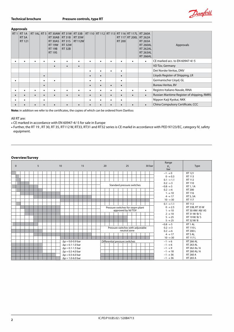
Approvals
• • • • • • • • • • • • • CE marked acc. to EN 60947-4/-5
• • • VD Tüv, Germany
• • • • Det Norske Veritas, DNV
• • • • Lloyds Register of Shipping, LR
• • • • • • Germanischer Lloyd, GL
• • • • • Bureau Veritas, BV
• • • • • • • • • • • • • Registro Italiano Navale, RINA
• • • • • • • • • • • • • Russian Maritime Register of shipping, RMRS
• • • • • • • Nippon Kaiji Kyokai, NKK
• • • • • • • • • • • • • China Compulsory Certificate, CCC
Note: in addition we refer to the certificates, the copies of which can be ordered from Danfoss
All RT are:• CE marked in accordance with EN 60947-4/-5 for sale in Europe• Further, the RT 19 , RT 30, RT 35, RT112 W, RT33, RT31 and RT32 series is CE markd in accordance with PED 97/23/EC, category IV, safety equipment.
Approvals
Overview/Survey
0 5 10 15 20 25 30 barRange
pebar
Type
−1 → 0 0 → 0.3 0.1 → 1.1 0.2 → 3 −0.8 → 5 0.2 → 6 1 → 10 4 → 17 10 → 30
RT 121RT 113RT 112RT 110RT 1, 1ART 200RT 116RT 5, 5ART 117
Standard pressure switches
0.1 → 1.1 0 → 2.5 1 → 10 2 → 10 5 → 25 5 → 25
RT 112RT 33B, RT 35 WRT 30 AW/ AB/ ASRT 31 W/ B/ SRT 19 W/ B/ SRT 32 W/ B
Pressure switches for steam plant approved by Vd TÜV
−0.8 → 5 0.2 → 3 0.2 → 6 4 → 17 10 → 30
RT 1 ALRT 110 LRT 200 LRT 5 ALRT 117 L
Pressure switches with adjustable neutral zone
Δp = 0.0-0.9 barΔp = 0.1-1.0 barΔp = 0.1-1.5 barΔp = 0.5-4.0 barΔp = 0.5-6.0 barΔp = 1.0-6.0 bar
Differential pressure switches −1 → 6 −1 → 6 −1 → 9 −1 → 18 −1 → 36 −1 → 36
RT 266 ALRT 263 ALRT 262 AL/ ART 260 AL/ ART 260 ART 265 A
2
3
Technical brochure Pressure controls, type RT
IC.PD.P10.B5.02 / 520B4713
Regulation range(pe )bar
Mechanical differential
bar
Adjustableneutral zone
bar
Max. operating
pressure, PBbar
Max. testpressure
p’bar
Pressure connection Code no. Type
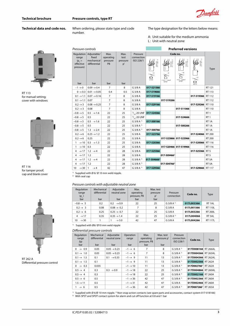
−0.8 → 5 0.2 0.2 → 0.9 22 25 G 3/8 A 1) 017L003366 RT 1AL
0.2 → 3 0.08 0.08 → 0.2 7 8 G 3/8 A 017L001566 RT 110L
0.2 → 6 0.25 0.25 → 0.7 22 25 G 3/8 A 017L003266 RT 200L
4 → 17 0.35 0.35 → 1.4 22 25 G 3/8 A 1) 017L004066 RT 5AL
10 → 30 1 1 → 3.0 42 47 G 3/8 A 017L004266 RT 117L
Regulation range
Δp bar
Mechanical differential
bar
Adjustable neutral zone
bar
Operation range
bar
Max. operating
pressure, PBbar
Max. test pressure p’
bar
Pressure connectionISO 228/1 Code no. Type
0 → 0.9 0.05 0.05 → 0.23 −1 → 6 7 8 G 3/8 A 1) 017D008166 RT 266AL
0.1 → 1.0 0.05 0.05 → 0.23 −1 → 6 7 8 G 3/8 A 1) 017D004566 RT 263AL
0.1 → 1.5 0.1 0.1 → 0.33 −1 → 9 11 13 G 3/8 A 1) 017D004366 RT 262AL
0.1 → 1.5 0.1 −1 → 9 11 13 G 3/8 A 1) 017D002566 RT 262A
0 → 0.3 0.035 −1 → 10 11 13 G 3/8 A 1) 017D0027662) RT 262A
0.5 → 4 0.3 0.3 → 0.9 −1 → 18 22 25 G 3/8 A 1) 017D004866 RT 260AL
0.5 → 4 0.3 −1 → 18 22 25 G 3/8 A 1) 017D002166 RT 260A
0.5 → 6 0.5 −1 → 36 42 47 G 3/8 A 1) 017D002366 RT 260A
1.5 → 11 0.5 −1 → 31 42 47 G 3/8 A 017D002466 RT 260A
1 → 6 0.5 −1 → 36 42 47 G 3/8 A 1) 017D0072663) RT 265A
Regulation range(pe =
effective pressure)
bar
Adjustable/fixed
mechanical differential
bar
Max. operating pressure
PB
bar
Max.test
pressurep’
bar
PressureconnectionISO 228/1
Code no.
Type
−1 → 0 0.09 → 0.4 7 8 G 3/8 A 017-521566 RT 121
0 → 0.3 0.01 → 0.05 0.4 0.5 G 3/8 A 017-519666 RT 113
0.1 → 1.1 0.07 → 0.16 7 8 G 3/8 A 017-519166 017-519366 RT 112
0.1 → 1.1 0.07 7 8 G 3/8 A 017-519266 RT 112
0.2 → 3 0.08 → 0.25 7 8 G 3/8 A 017-529166 017-529266 RT 110
0.2 → 3 0.08 7 8 G 3/8 A 017-511066 RT 110
−0.8 → 5 0.5 → 1.6 22 25 7/16-20 UNF 017-524566 RT 1
−0.8 → 5 0.5 22 25 7/16-20 UNF 017-524666 RT 1
−0.8 → 5 0.5 → 1.6 22 25 G 3/8 A 1) 017-500166 RT 1A
−0.8 → 5 0.5 22 25 G 3/8 A 1) 017-500266 RT 1A
−0.8 → 5 1.3 → 2.4 22 25 G 3/8 A 1) 017-500766 RT 1A
0.2 → 6 0.25 → 1.2 22 25 G 3/8 A 017-523766 017-524066 RT 200
0.2 → 6 0.25 22 25 G 3/8 A 017-523866 017-523966 RT 200
1 → 10 0.3 → 1.3 22 25 G 3/8 A 017-520366 017-520066 RT 116
1 → 10 0.3 22 25 G 3/8 A 017-520466 017-519966 RT 116
4 → 17 1.2 → 4 22 28 G 3/8 A 017-525566 017-525366 RT 5
4 → 17 1.2 22 28 G 3/8 A 017-5094662) RT 5
4 → 17 1.2 → 4 22 28 G 3/8 A 1) 017-5046662) RT 5A
4 → 17 1.2 22 28 G 3/8 A 1) 017-5047662) RT 5A
10 → 30 1 → 4 42 47 G 3/8 A 1) 017-529566 017-529666 RT 117
Technical data and code nos. When ordering, please state type and code number.
The type designation for the letters below means:
A : Unit suitable for the medium ammoniaL : Unit with neutral zone
Pressure controls Preferred versions
RT 113 for manual setting;cover with windows
RT 116 for tamper proof;cap and blank cover
RT 262 A Differential pressure control
Pressure controls with adjustable neutral zone
Differential pressure controls
1) Supplied with Ø 6/Ø 10 mm nipple. 2) Non-snap action contacts (see spare parts and accessories, contact system 017-018166)3) With SPST and SPDT contact system for alarm and cut off function at 0.8 and 1 bar
1) Supplied with Ø6/ Ø10 mm weld nipple
1) Supplied with Ø 6/ Ø 10 mm weld nipple.2) With seal cap
3
4
Technical brochure Pressure controls, type RT
IC.PD.P10.B5.02 / 520B4713
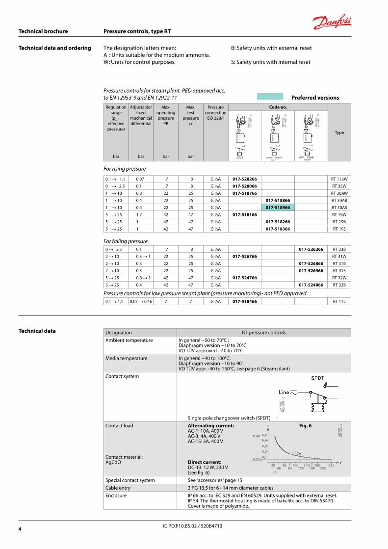
0.1 → 1.1 0.07 7 8 G ½A 017-528266 RT 112W
0 → 2.5 0.1 7 8 G ½A 017-528066 RT 35W
1 → 10 0.8 22 25 G ½A 017-518766 RT 30AW
1 → 10 0.4 22 25 G ½A 017-518866 RT 30AB
1 → 10 0.4 22 25 G ½A 017-518966 RT 30AS
5 → 25 1.2 42 47 G ½A 017-518166 RT 19W
5 → 25 1 42 47 G ½A 017-518266 RT 19B
5 → 25 1 42 47 G ½A 017-518366 RT 19S
0 → 2.5 0.1 7 8 G ½A 017-526266 RT 33B
2 → 10 0.3 → 1 22 25 G ½A 017-526766 RT 31W
2 → 10 0.3 22 25 G ½A 017-526866 RT 31B
2 → 10 0.3 22 25 G ½A 017-526966 RT 31S
5 → 25 0.8 → 3 42 47 G ½A 017-524766 RT 32W
5 → 25 0.4 42 47 G ½A 017-524866 RT 32B
0.1 → 1.1 0.07 → 0.16 7 7 G ½A 017-518466 RT 112
B: Safety units with external reset
S: Safety units with internal reset
The designation letters mean:A : Units suitable for the medium ammonia.W : Units for control purposes.
Pressure controls for steam plant, PED approved acc. to EN 12953-9 and EN 12922-11 Preferred versions
Regulation range(pe =
effective pressure)
bar
Adjustable/fixed
mechanical differential
bar
Max. operating pressure
PB
bar
Max.test
pressurep’
bar
PressureconnectionISO 228/1
Code no.
Type
For rising pressure
For falling pressure
Pressure controls for low pressure steam plant (pressure monitoring)- not PED approved
Technical data and ordering
Technical data Designation RT pressure controlsAmbient temperature In general −50 to 70°C ;
Diaphragm version −10 to 70°CVD TÜV approved −40 to 70°C
Media temperature In general −40 to 100°C; Diaphragm version −10 to 90°; VD TÜV appr. -40 to 150°C, see page 6 (Steam plant)
Contact system
Single-pole changeover switch (SPDT)Contact load
Contact material:AgCdO
Alternating current: Fig. 6AC-1: 10A, 400 VAC-3: 4A, 400 VAC-15: 3A, 400 V
Direct current:DC-13: 12 W, 230 V(see fig. 6)
Special contact system See “accessories” page 15Cable entry 2 PG 13.5 for 6 - 14 mm diameter cablesEnclosure IP 66 acc. to IEC 529 and EN 60529. Units supplied with external reset.
IP 54. The thermostat housing is made of bakelite acc. to DIN 53470Cover is made of polyamide.
4
5
Technical brochure Pressure controls, type RT
IC.PD.P10.B5.02 / 520B4713
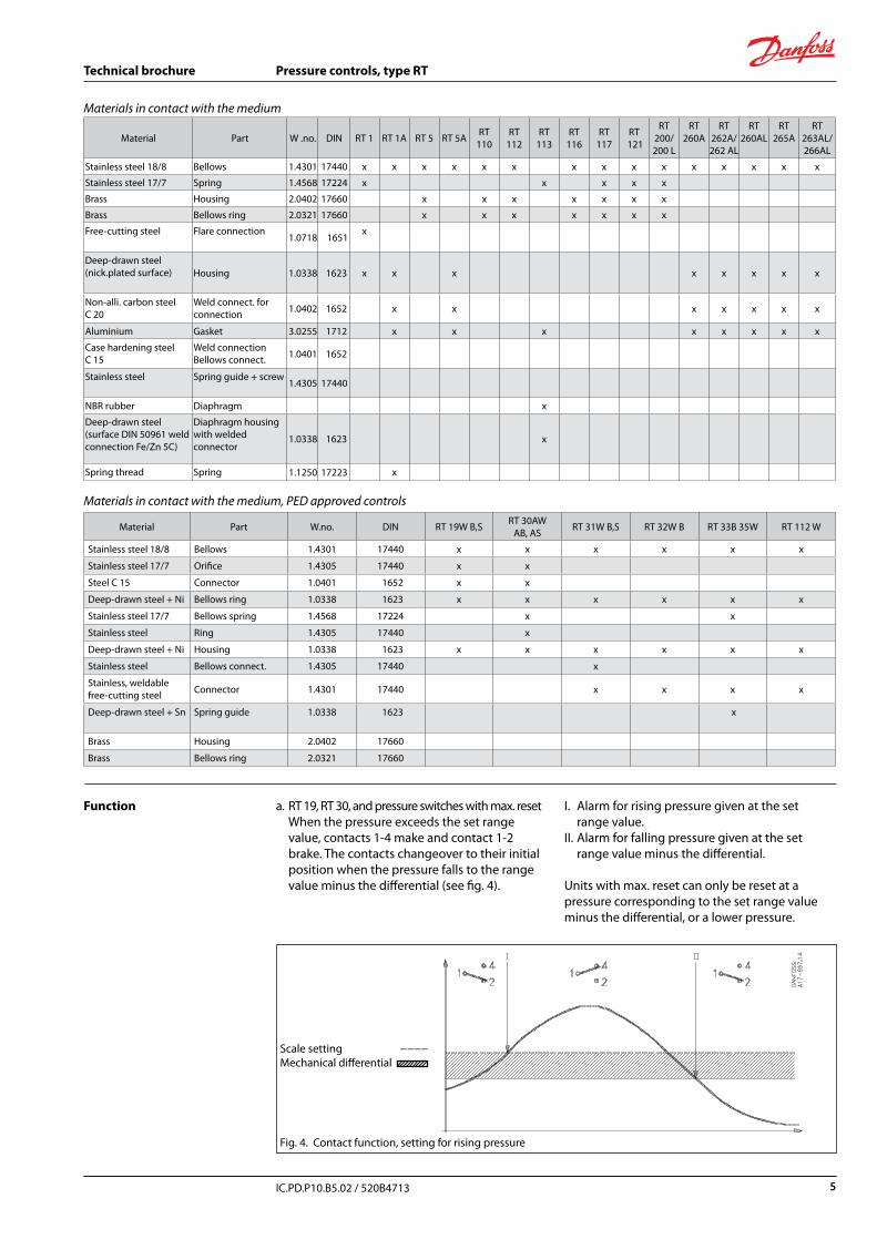
Materials in contact with the medium
Material Part W .no. DIN RT 1 RT 1A RT 5 RT 5A RT 110
RT 112
RT 113
RT116
RT 117
RT 121
RT 200/200 L
RT 260A
RT 262A/262 AL
RT 260AL
RT 265A
RT 263AL/ 266AL
Stainless steel 18/8 Bellows 1.4301 17440 x x x x x x x x x x x x x x x
Stainless steel 17/7 Spring 1.4568 17224 x x x x x
Brass Housing 2.0402 17660 x x x x x x x
Brass Bellows ring 2.0321 17660 x x x x x x x
Free-cutting steel Flare connection1.0718 1651
x
Deep-drawn steel(nick.plated surface) Housing 1.0338 1623 x x x x x x x x
Non-alli. carbon steel C 20
Weld connect. for connection 1.0402 1652 x x x x x x x
Aluminium Gasket 3.0255 1712 x x x x x x x x
Case hardening steel C 15
Weld connectionBellows connect. 1.0401 1652
Stainless steel Spring guide + screw1.4305 17440
NBR rubber Diaphragm x
Deep-drawn steel (surface DIN 50961 weld connection Fe/Zn 5C)
Diaphragm housing with welded connector
1.0338 1623 x
Spring thread Spring 1.1250 17223 x
Materials in contact with the medium, PED approved controls
Material Part W.no. DIN RT 19W B,S RT 30AW AB, AS RT 31W B,S RT 32W B RT 33B 35W RT 112 W
Stainless steel 18/8 Bellows 1.4301 17440 x x x x x x
Stainless steel 17/7 Orifice 1.4305 17440 x x
Steel C 15 Connector 1.0401 1652 x x
Deep-drawn steel + Ni Bellows ring 1.0338 1623 x x x x x x
Stainless steel 17/7 Bellows spring 1.4568 17224 x x
Stainless steel Ring 1.4305 17440 x
Deep-drawn steel + Ni Housing 1.0338 1623 x x x x x x
Stainless steel Bellows connect. 1.4305 17440 x
Stainless, weldable free-cutting steel Connector 1.4301 17440 x x x x
Deep-drawn steel + Sn Spring guide 1.0338 1623 x
Brass Housing 2.0402 17660
Brass Bellows ring 2.0321 17660
Function a. RT 19, RT 30, and pressure switches with max. resetWhen the pressure exceeds the set range value, contacts 1-4 make and contact 1-2 brake. The contacts changeover to their initial position when the pressure falls to the range value minus the differential (see fig. 4).
I. Alarm for rising pressure given at the set range value.II. Alarm for falling pressure given at the set
range value minus the differential.
Units with max. reset can only be reset at a pressure corresponding to the set range value minus the differential, or a lower pressure.
Scale setting −−−−Mechanical differential
Fig. 4. Contact function, setting for rising pressure
5
6
Technical brochure Pressure controls, type RT
IC.PD.P10.B5.02 / 520B4713
Function(continued)
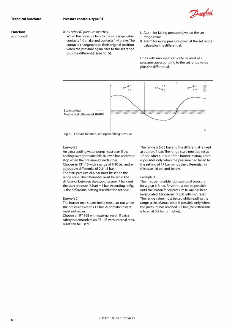
b. All other RT pressure switches When the pressure falls to the set range value,
contacts 1-2 make and contacts 1-4 brake. The contacts changeover to their original position when the pressure again rises to the set range plus the differential (see fig. 5).
Fig. 5. Contact funktion, setting for falling pressure
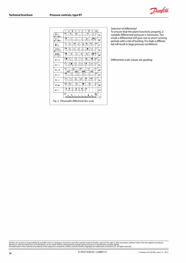
Example 1An extra cooling water pump must start if the cooling water pressure falls below 6 bar, and must stop when the pressure exceeds 7 bar. Choose an RT 116 with a range of 1-10 bar and an adjustable differential of 0.2-1.3 bar.The start pressure of 6 bar must be set on the range scale. The differential must be set as the difference between the stop pressure (7 bar) and the start pressure (6 bar) = 1 bar. According to fig. 3, the differential setting disc must be set on 8.
Example 2The burner on a steam boiler must cut out when the pressure exceeds 17 bar. Automatic restart must not occur.Choose an RT 19B with external reset. If extra safety is demanded, an RT 19S with internal max. reset can be used.
I. Alarm for falling pressure given at the set range value.
II. Alarm for rising pressure given at the set range value plus the differential.
Units with min. reset can only be reset at a pressure corresponding to the set range value plus the differential.
The range is 5-25 bar and the differential is fixed at approx. 1 bar. The range scale must be set at 17 bar. After cut-out of the burner, manual reset is possible only when the pressure had fallen to the setting of 17 bar minus the differential: in this case, 16 bar and below.
Example 3 The min. permissible lubricating oil pressure for a gear is 3 bar. Reset must not be possible until the reason for oil pressure failure has been investigated. Choose an RT 200 with min. reset.The range value must be set while reading the range scale. Manual reset is possible only when the pressure has reached 3.2 bar (the differential is fixed at 0.2 bar or higher).
Scale setting −−−−Mechanical differential
6

7
Technical brochure Pressure controls, type RT
IC.PD.P10.B5.02 / 520B4713
Functional description of RT units with fail-safe design
Fail-safe function for falling pressureFig. 5a shows a cross-section of a bellows element for the RT 32W with fail-safe function for falling pressure. On rising pressure the contact arm is actuated to break the connection between terminals 1 and 2.
On falling pressure the contact arm is actuated to break the connection between terminals 1 and 4. If a defect occurs in the bellows the setting spring actuates the contact arm to break the connection between terminals 1 and 4, as in the case of falling pressure. This will occur irrespective of the pressure on the bellows.
Fail-safe function for rising pressureFig. 5b shows a cross-section through a bellows element for the RT 30W with fail-safe for rising pressure. On rising pressure the contact arm is actuated to break the connection between terminals 1 and 2 .
If a defect occurs in the inner bellows the pressure is led to the outer bellows. The outer bellows has an area three times as large as the inner bellows. The connection between terminals 1 and 2 becomes broken.
If a defect occurs in the outer bellows, there will be atmospheric pressure in the gap between the two bellows. This actuates the contact system to break the connection between terminals 1 and 2. The important factor with the double bellows design is the vacuum between the two bellows, and that in case of bellows break, no media will leak into the environment.
Fig 5a
Fig. 5b
Pressure switches for liquid level control RT 113
3. Connection to the side of the tank with the RT 113 below the liquid level
Where possible, this form of connection should be used. If an air-absorbing liquid like oil is involved, it is preferable to 1 and 2. The resulting range setting is the distance from the liquid surface to the centre of the diaphragm housing.
4. Connection in the tank with the RT 113 above the liquid level
This method is for use with air-absorbing liquids where connection type 3 is not possible. The shortest horizontal tube length is determined as described in 2. A shut-off valve is installed between the oil tank and water reservoir shown so that impurities can be drained from the water reservoir through a bottom drain plug. Fresh water can then be poured into the reservoir through a filling connector in its top.
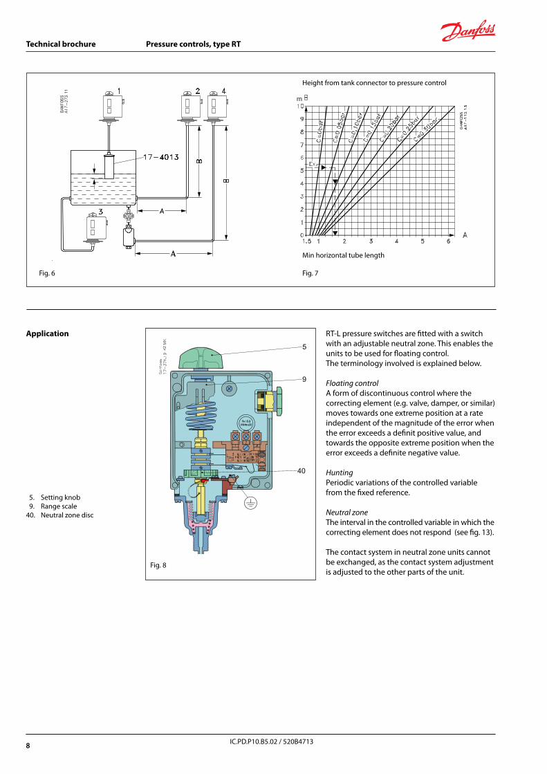
The RT 113 pressure switch can be used to control the liquid level in open tanks. Fig. 6 shows in principle, four different types of installation.
1. With air bell (see “Accessories”) For control purpose, the air bell should be
installed 20 to 40 mm below the lowest liquid level. In addition, the tube between the RT 113 and the air bell must be absolutely airtight. If only an indication is required, the bell can be placed 100 mm below the max. level. The RT 113 must be set at 0 cm wg and the differential disc on 1.
2. Connection to the side of the tank with the RT 113 above the liquid level
The horizontal tube A must have a certain length in relation to the vertical tube B in order to ensure reliable control. The length ofA can be found from fig. 7, using B and the range setting pressure C.
7
8
Technical brochure Pressure controls, type RT
IC.PD.P10.B5.02 / 520B4713
Fig. 6
Min horizontal tube length
Fig. 7
Application RT-L pressure switches are fitted with a switch with an adjustable neutral zone. This enables the units to be used for floating control. The terminology involved is explained below.
Floating controlA form of discontinuous control where the correcting element (e.g. valve, damper, or similar) moves towards one extreme position at a rate independent of the magnitude of the error when the error exceeds a definit positive value, and towards the opposite extreme position when the error exceeds a definite negative value.
HuntingPeriodic variations of the controlled variable from the fixed reference.
Neutral zoneThe interval in the controlled variable in which the correcting element does not respond (see fig. 13).
The contact system in neutral zone units cannot be exchanged, as the contact system adjustment is adjusted to the other parts of the unit.
5. Setting knob 9. Range scale 40. Neutral zone disc
Fig. 8
Height from tank connector to pressure control
8
9
Technical brochure Pressure controls, type RT
IC.PD.P10.B5.02 / 520B4713
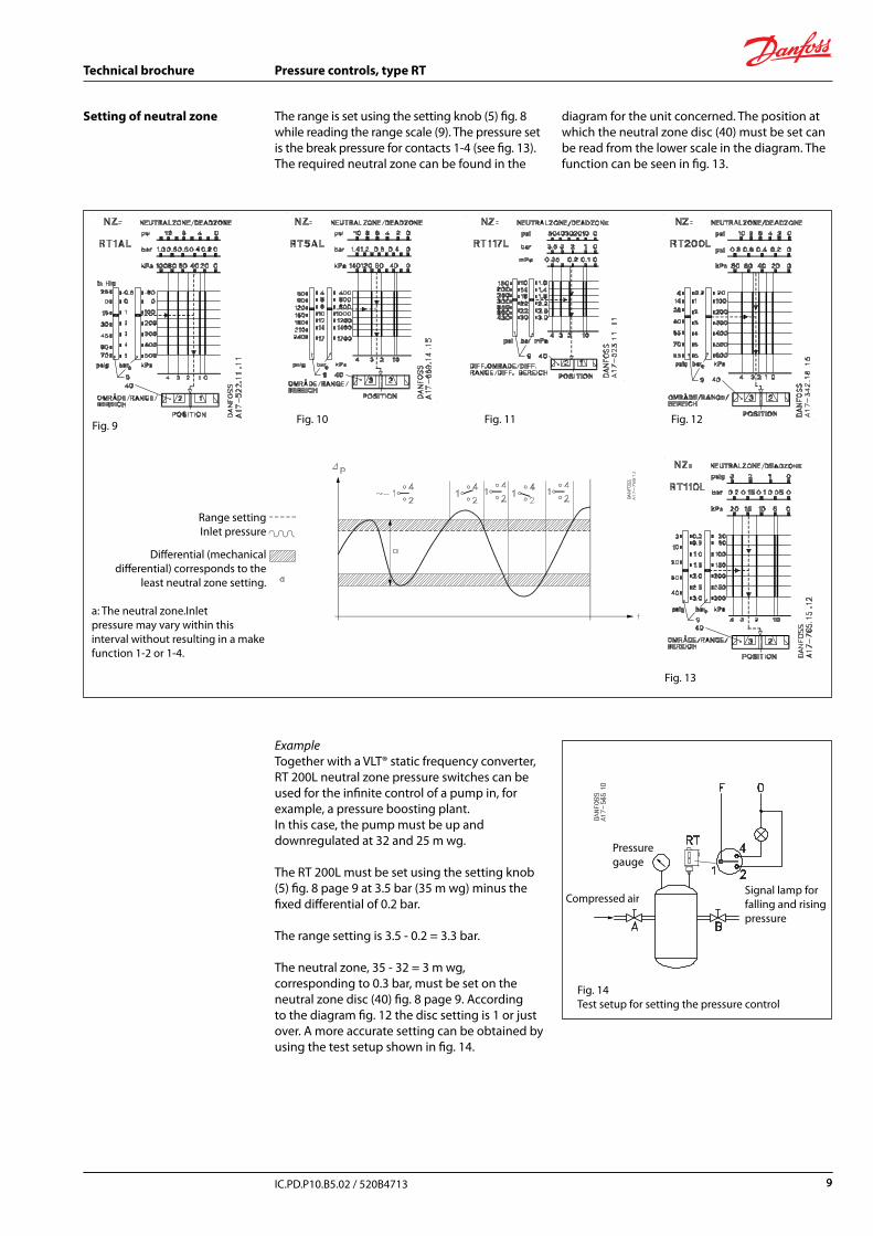
Setting of neutral zone The range is set using the setting knob (5) fig. 8 while reading the range scale (9). The pressure set is the break pressure for contacts 1-4 (see fig. 13).The required neutral zone can be found in the
Fig. 9
Fig. 13
ExampleTogether with a VLT® static frequency converter, RT 200L neutral zone pressure switches can be used for the infinite control of a pump in, for example, a pressure boosting plant.In this case, the pump must be up and downregulated at 32 and 25 m wg.
The RT 200L must be set using the setting knob (5) fig. 8 page 9 at 3.5 bar (35 m wg) minus the fixed differential of 0.2 bar.
The range setting is 3.5 - 0.2 = 3.3 bar.
The neutral zone, 35 - 32 = 3 m wg, corresponding to 0.3 bar, must be set on the neutral zone disc (40) fig. 8 page 9. According to the diagram fig. 12 the disc setting is 1 or just over. A more accurate setting can be obtained by using the test setup shown in fig. 14.
Pressure gauge
Compressed airSignal lamp for falling and rising pressure
Fig. 14Test setup for setting the pressure control
Fig. 10 Fig. 11 Fig. 12
diagram for the unit concerned. The position at which the neutral zone disc (40) must be set can be read from the lower scale in the diagram. The function can be seen in fig. 13.
Range settingInlet pressure
Differential (mechanical differential) corresponds to the
least neutral zone setting.
a: The neutral zone.Inlet pressure may vary within this interval without resulting in a make function 1-2 or 1-4.
9
10
Technical brochure Pressure controls, type RT
IC.PD.P10.B5.02 / 520B4713
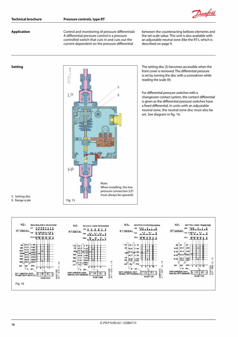
Application Control and monitoring of pressure differentialsA differential pressure control is a pressure controlled switch that cuts in and cuts out the current dependent on the pressure differential
between the counteracting bellows elements and the set scale value. This unit is also available with an adjustable neutral zone (like the RT-L which is described on page 9.
The setting disc (5) becomes accessible when the front cover is removed. The differential pressure is set by turning the disc with a screwdriver while reading the scale (9).
For differential pressure switches with a changeover contact system, the contact differential is given as the differential pressure switches have a fixed differential. In units with an adjustable neutral zone, the neutral zone disc must also be set. See diagram in fig. 16.
5. Setting disc9. Range scale
Setting
Note:When installing, the low pressure connection (LP) must always be upwards
Fig. 15
Fig. 16
10
11
Technical brochure Pressure controls, type RT
IC.PD.P10.B5.02 / 520B4713
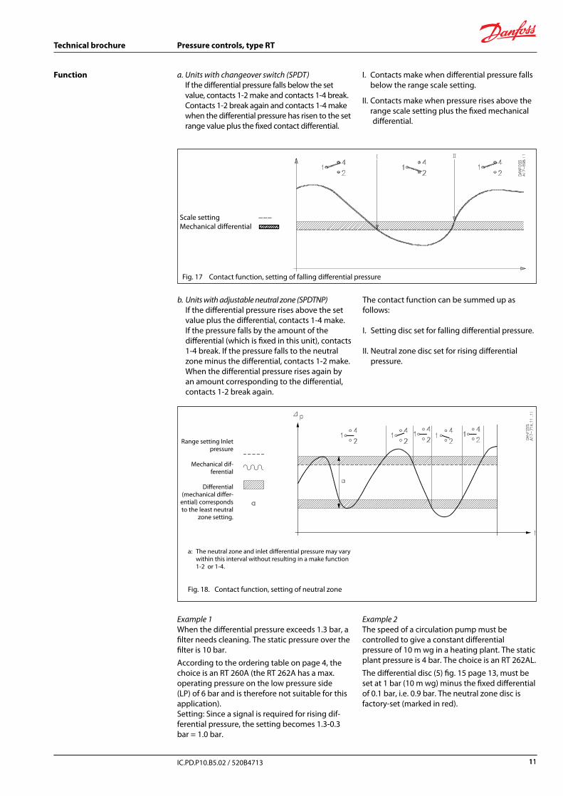
Function a. Units with changeover switch (SPDT) If the differential pressure falls below the set
value, contacts 1-2 make and contacts 1-4 break. Contacts 1-2 break again and contacts 1-4 make
when the differential pressure has risen to the set range value plus the fixed contact differential.
Scale setting −−−Mechanical differential
Range setting Inlet pressure
Mechanical dif-ferential
Differential (mechanical differ-
ential) corresponds to the least neutral
zone setting.
b. Units with adjustable neutral zone (SPDTNP) If the differential pressure rises above the set
value plus the differential, contacts 1-4 make. If the pressure falls by the amount of the
differential (which is fixed in this unit), contacts 1-4 break. If the pressure falls to the neutral zone minus the differential, contacts 1-2 make. When the differential pressure rises again by an amount corresponding to the differential, contacts 1-2 break again.
The contact function can be summed up as follows:
I. Setting disc set for falling differential pressure.
II. Neutral zone disc set for rising differential pressure.
a: The neutral zone and inlet differential pressure may vary within this interval without resulting in a make function 1-2 or 1-4.
Fig. 18. Contact function, setting of neutral zone
Example 1When the differential pressure exceeds 1.3 bar, a filter needs cleaning. The static pressure over the filter is 10 bar.
According to the ordering table on page 4, the choice is an RT 260A (the RT 262A has a max. operating pressure on the low pressure side (LP) of 6 bar and is therefore not suitable for this application).Setting: Since a signal is required for rising dif-ferential pressure, the setting becomes 1.3-0.3 bar = 1.0 bar.
Example 2The speed of a circulation pump must be controlled to give a constant differential pressure of 10 m wg in a heating plant. The static plant pressure is 4 bar. The choice is an RT 262AL.
The differential disc (5) fig. 15 page 13, must be set at 1 bar (10 m wg) minus the fixed differential of 0.1 bar, i.e. 0.9 bar. The neutral zone disc is factory-set (marked in red).
Fig. 17 Contact function, setting of falling differential pressure
I. Contacts make when differential pressure falls below the range scale setting.
II. Contacts make when pressure rises above the range scale setting plus the fixed mechanical differential.
11

12
Technical brochure Pressure controls, type RT
IC.PD.P10.B5.02 / 520B4713
RT 30 AW, -B, -S L = 225RT 19 W, -B, -S L = 228RT 33 B, 35W L = 221RT 112 W L = 210RT 31 W-B, -S L = 212RT 32 W-B L = 212
RT 13 RT 5, 110, 112, 116, 117, 117L, 121, 200, 200L
RT 5 RT 1A, 1AL
RT 260A, 260AL RT 262A, 262AL, 263AL
RT 5A, 5ALRT 5
Dimensions and weight
Weight: approx. 1 kg
RT 5, 110, 112, 116, 117, 200Special version with tamper proof cap and blank cover
: External reset knob only for RT...B
12
13
Technical brochure Pressure controls, type RT
IC.PD.P10.B5.02 / 520B4713
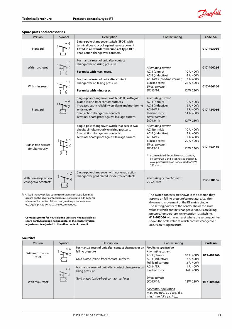
Spare parts and accessories Version Symbol Description Contact rating Code no.
Standard
Single-pole changeover switch (SPDT) withterminal board proof against leakate current Fitted in all standard versions of type RT1).Snap action changeover contacts.
Alternating current: AC-1 (ohmic): 10 A, 400 VAC-3 (inductive): 4 A, 400 VAC-14/15 (coil/transformer): 3 A, 400 VBlocked rotor: 28 A, 400 V Direct current: DC 13/14: 12 W, 230 V
017-403066
With max. reset
For manual reset of unit after contactchangeover on rising pressure
For units with max. reset.017-404266
With min. reset
For manual reset of units after contactchangeover on falling pressure.
For units with min. reset.017-404166
Standard
Single-pole changeover switch (SPDT) with gold plated (oxide-free) contact surfaces.Increases cut-in reliability on alarm and monitoring systems, etc.Snap action changeover contacts.Terminal board proof against leakage current.
Alternating currentAC-1 (ohmic): 10 A, 400 VAC-3 (inductive): 2 A, 400 VAC-14/15 1 A, 400 VBlocked rotor: 14 A, 400 V Direct current:DC-13/14: 12 W, 230 V
017-424066
Cuts in two circuits simultaneously
Single-pole changeover switch that cuts in two circuits simultaneously on rising pressure. Snap action changeover contacts.Terminal board proof against leakage current.
Alternating current:AC-1(ohmic): 10 A, 400 VAC-3 (inductive): 3 A, 400 VAC-14/15 2 A, 400 VBlocked rotor: 20 A, 400 VDirect current:DC-13/14: 12 W, 230 V
* If current is led through contacts 2 and 4, i.e. terminals 2 and 4 connected but not 1, max. permissible load is increased to 90 W, 220 V - - -.
017-403466
With non-snap action changeover contacts
Single-pole changeover with non-snap action changeover gold plated (oxide-free) contacts.
Alternating or direct current:25 VA, 24 V 017-018166
1) At load types with low currents/voltages contact failure may occure on the silver contacts because of oxidation. In systems where such a contact failure is of great importance (alarm etc.), gold plated contacts are recommended.
Contact systems for neutral zone units are not available as spare parts. Exchange not possible, as the contact system adjustment is adjusted to the other parts of the unit.
The switch contacts are shown in the position they assume on falling pressure/temperature, i.e. after downward movement of the RT main spindle.The setting pointer of the control shows the scale value at which contact changeover occurs on falling pressure/temperature. An exception is switch no. 017-403066 with max. reset where the setting pointer shows the scale value at which contact changeover occurs on rising pressure.
Version Symbol Description Contact rating Code no.
With min. manual reset
For manual reset of unit after contact changeover on falling pressure.
Gold plated (oxide-free) contact surfaces
For Alarm application Alternating current: AC-1 (ohmic): 10 A, 400 V AC-3 (inductive): 2 A, 400 V Full load current: 2 A, 400 V AC-14/15: 1 A, 400 V Blocked rotor: 14A, 400 V Direct current DC-13/14: 12W, 230 V For control application max. 100 mA / 30 V a.c./ d.c. min. 1 mA / 5 V a.c. / d.c.
017-404766
With max. reset
For manual reset of unit after contact changeover on rising pressure.
Gold plated (oxide-free) contact surfaces017-404866
Switches
13
14
Technical brochure Pressure controls, type RT
IC.PD.P10.B5.02 / 520B4713
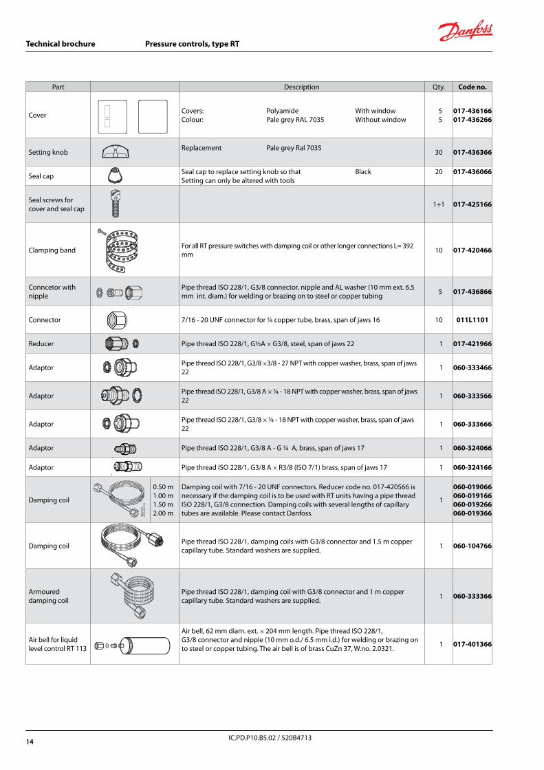
Part Description Qty. Code no.
Cover Covers: Polyamide With windowColour: Pale grey RAL 7035 Without window
5 5
017-436166017-436266
Setting knob Replacement Pale grey Ral 7035 30 017-436366
Seal cap Seal cap to replace setting knob so that BlackSetting can only be altered with tools
20 017-436066
Seal screws for cover and seal cap 1+1 017-425166
Clamping bandFor all RT pressure switches with damping coil or other longer connections L= 392 mm 10 017-420466
Conncetor with nipple
Pipe thread ISO 228/1, G3/8 connector, nipple and AL washer (10 mm ext. 6.5 mm int. diam.) for welding or brazing on to steel or copper tubing 5 017-436866
Connector 7/16 - 20 UNF connector for ¼ copper tube, brass, span of jaws 16 10 011L1101
Reducer Pipe thread ISO 228/1, G½A × G3/8, steel, span of jaws 22 1 017-421966
Adaptor Pipe thread ISO 228/1, G3/8 ×3/8 - 27 NPT with copper washer, brass, span of jaws 22 1 060-333466
AdaptorPipe thread ISO 228/1, G3/8 A × ¼ - 18 NPT with copper washer, brass, span of jaws 22 1 060-333566
Adaptor Pipe thread ISO 228/1, G3/8 × ¼ - 18 NPT with copper washer, brass, span of jaws 22 1 060-333666
Adaptor Pipe thread ISO 228/1, G3/8 A - G ¼ A, brass, span of jaws 17 1 060-324066
Adaptor Pipe thread ISO 228/1, G3/8 A × R3/8 (ISO 7/1) brass, span of jaws 17 1 060-324166
Damping coil
0.50 m1.00 m1.50 m2.00 m
Damping coil with 7/16 - 20 UNF connectors. Reducer code no. 017-420566 is necessary if the damping coil is to be used with RT units having a pipe thread ISO 228/1, G3/8 connection. Damping coils with several lengths of capillary tubes are available. Please contact Danfoss.
1
060-019066060-019166060-019266060-019366
Damping coil Pipe thread ISO 228/1, damping coils with G3/8 connector and 1.5 m copper capillary tube. Standard washers are supplied. 1 060-104766
Armoured damping coil
Pipe thread ISO 228/1, damping coil with G3/8 connector and 1 m copper capillary tube. Standard washers are supplied. 1 060-333366
Air bell for liquid level control RT 113
Air bell, 62 mm diam. ext. × 204 mm length. Pipe thread ISO 228/1, G3/8 connector and nipple (10 mm o.d./ 6.5 mm i.d.) for welding or brazing on to steel or copper tubing. The air bell is of brass CuZn 37, W.no. 2.0321. 1 017-401366
14
15
Technical brochure Pressure controls, type RT
IC.PD.P10.B5.02 / 520B4713
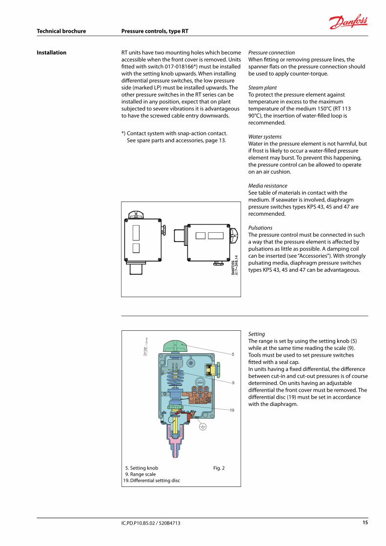
RT units have two mounting holes which become accessible when the front cover is removed. Units fitted with switch 017-018166*) must be installed with the setting knob upwards. When installing differential pressure switches, the low pressure side (marked LP) must be installed upwards. The other pressure switches in the RT series can be installed in any position, expect that on plant subjected to severe vibrations it is advantageous to have the screwed cable entry downwards.
*) Contact system with snap-action contact. See spare parts and accessories, page 13.
Pressure connectionWhen fitting or removing pressure lines, the spanner flats on the pressure connection should be used to apply counter-torque.
Steam plantTo protect the pressure element against temperature in excess to the maximum temperature of the medium 150°C (RT 113 90°C), the insertion of water-filled loop is recommended.
Water systemsWater in the pressure element is not harmful, but if frost is likely to occur a water-filled pressure element may burst. To prevent this happening, the pressure control can be allowed to operate on an air cushion.
Media resistanceSee table of materials in contact with the medium. If seawater is involved, diaphragm pressure switches types KPS 43, 45 and 47 are recommended.
PulsationsThe pressure control must be connected in such a way that the pressure element is affected by pulsations as little as possible. A damping coil can be inserted (see “Accessories”). With strongly pulsating media, diaphragm pressure switches types KPS 43, 45 and 47 can be advantageous.
Installation
5. Setting knob 9. Range scale19. Differential setting disc
SettingThe range is set by using the setting knob (5) while at the same time reading the scale (9). Tools must be used to set pressure switches fitted with a seal cap. In units having a fixed differential, the difference between cut-in and cut-out pressures is of course determined. On units having an adjustable differential the front cover must be removed. The differential disc (19) must be set in accordance with the diaphragm.
Fig. 2
15
16
Technical brochure Pressure controls, type RT
IC.PD.P10.B5.02 / 520B4713
Selection of differentialTo ensure that the plant functions properly, a suitable differential pressure is necessary. Too small a differential will give rise to short running periods with a risk of hunting. Too high a differen-tial will result in large pressure oscillations.
Differential scale values are guiding
Fig. 3 Obtainable differential disc scale
16 © Danfoss A/S (IA-MO / jmn), 12 - 2011


![mh;.;rt a;idpvR - astrojyoti.com · mh;.;rt a;idpvR ≈Ig,ex;y nm" aq p[qmoå?y;y" — n;r;y,' nmS’Ty nr ' c wv nroˇmm (devI ' srSvtI ' c wv tto jym udIry et(lomhWR,p u] ¨g [≈v;"](https://img.pdfslide.us/doc/110x75/5adffdf87f8b9a8f298da155/mhrt-aidpvr-rt-aidpvr-igexy-nm-aq-pqmoyy-nry-nmsty-nr.jpg)