Embed Size (px)
Citation preview

HAL Id: hal-03020637https://hal.archives-ouvertes.fr/hal-03020637
Submitted on 24 Nov 2020
HAL is a multi-disciplinary open accessarchive for the deposit and dissemination of sci-entific research documents, whether they are pub-lished or not. The documents may come fromteaching and research institutions in France orabroad, or from public or private research centers.
L’archive ouverte pluridisciplinaire HAL, estdestinée au dépôt et à la diffusion de documentsscientifiques de niveau recherche, publiés ou non,émanant des établissements d’enseignement et derecherche français ou étrangers, des laboratoirespublics ou privés.
Finite Element based Redesign and Optimization ofAircraft Structural Components using Composite
MaterialsSergio Andrés Ardila-Parra, Carmine Pappalardo, Octavio Andrés González
Estrada, Domenico Guida
To cite this version:Sergio Andrés Ardila-Parra, Carmine Pappalardo, Octavio Andrés González Estrada, DomenicoGuida. Finite Element based Redesign and Optimization of Aircraft Structural Components usingComposite Materials. IAENG International Journal of Applied Mathematics, 2020. �hal-03020637�

Finite Element based Redesign and Optimizationof Aircraft Structural Components using
Composite MaterialsSergio Andres Ardila-Parra, Carmine Maria Pappalardo, Octavio Andres Gonzalez Estrada, Domenico Guida
Abstract—In the preliminary stage of the industrial design,the structural analysis of the components made of compos-ite materials is generally difficult to carry out for aircraftstructures having complex three-dimensional geometry. Moreimportantly, in the case of composite structures, the lay-upprocess creates a particular distribution of the material prop-erties that is challenging to simulate in a virtual environment.This research work is, therefore, focused on the use of the finiteelement method for the numerical analysis and the structuralredesign of the bulkhead and flap aircraft components. Inparticular, the numerical results obtained in this work arethe stress and strain fields of these mechanical components.The redesign and the structural optimization of these twomechanical components are performed employing a simplenumerical procedure. For this purpose, the quality of the stressand strain fields obtained by performing numerical experimentsis evaluated considering failure criteria suitable for compositestructures. Subsequently, the analysis developed in this studyis used for determining the performance of the material aswell as the number and orientation of the plies selected forthe composite components. The verification process performedin this work, on the other hand, consisted of a comparativeanalysis with the same aerospace components made of isotropicand anisotropic materials. The numerical results found are com-pared with the experimental results available for the aerospacecomponents that are geometrically and functionally similar tothe bulkhead. In general, a good agreement is found in thecomparison between the numerical and experimental results.
Index Terms—Finite element method, Design optimization,Component redesign, Structural analysis, Composite materials.
I. INTRODUCTION
The principal goal of this paper is to develop three-
dimensional mechanical models of the main structural com-
ponents of a general-aviation single-engine aircraft. The me-
chanical models constructed in this research work will serve
as the basis for the system parameter identification and the
structural health monitoring of aircraft components that will
be performed in future investigations [1]–[5]. Background
information, the formulation of the problem of interest for
this investigation, a short literature review, the scope and
S. A. Ardila-Parra is with the School of Mechanical Engineering,Universidad Industrial de Santander, Calle 27, 9, 680002 Bucaramanga,COLOMBIA (email: [email protected]).
C. M. Pappalardo is with the Department of Industrial Engineering,University of Salerno, Via Giovanni Paolo II, 132, 84084 Fisciano, Salerno,ITALY (corresponding author, email: [email protected]).
O. A. Gonzalez Estrada is with the School of Mechanical Engineering,Universidad Industrial de Santander, Calle 27, 9, 680002 Bucaramanga,COLOMBIA (email: [email protected]).
D. Guida is with the Department of Industrial Engineering, Universityof Salerno, Via Giovanni Paolo II, 132, 84084 Fisciano, Salerno, ITALY(email: [email protected]).
the contributions of this study, and the organization of the
manuscript are provided in this introductive section.
A. Background Information
In modern engineering design and manufacturing, the use
of computer-aided modeling and the performance assessment
by means of numerical simulation has conquered a central
role. Since computer simulations are becoming more and
more effective and efficient, well-defined computer models
allow for developing faster and cheaper processes for the
design cycle. However, it is apparent that the reliability of the
numerical results obtained employing computer simulations
depends on their accuracy, evaluated in comparison with
the experimental measurements obtained operating on the
actual physical system [6], [7]. It is, therefore, of paramount
importance for the engineer to develop appropriate computer
models of the physical system to be analyzed in order to be
able to construct a viable design.
Nowadays, commercial as well as free computational
finite element software have advanced capabilities based on
sound theoretical formulations. Once a computer model of
a physical system has been developed, the computational
tools embedded in the computer-aided software derive the
mathematical models which describe the physics of interest
for the system to be analyzed. However, the experience of
the engineer still plays a fundamental role in the preliminary
mechanical design phase, in the correct interpretation of
the numerical results obtained by using computational tools,
and in the iterative redesign process of a given structural
component [8], [9]. For instance, the tools of pre and post-
processing allow for assessing the quality of the desired
design solution and the subsequent detailed development and
optimization of the mechanical structure previously modeled
in a virtual environment [10], [11]. Also, these numerical
packages allow us for solving multiphysics problems, can
be used for performing the fatigue analysis, and provide
an estimation of the damage tolerance of a mechanical
part. Thus, the numerical solutions obtained in a virtual
environment by means of the mathematical models developed
by the engineer needs to be refined and interpreted, thereby
allowing for verification with the actual physical system of
interest.
The increasing complexity of the structural components
employed in modern engineering applications needs powerful
computational tools for analysis [12]. To this end, the most
used approaches are the Finite Element Method (FEM) and
the Boundary Elements Method (BEM) [13], [14]. Both
the FEM and the BEM represent effective computational
IAENG International Journal of Applied Mathematics, 50:4, IJAM_50_4_21
Volume 50, Issue 4: December 2020
______________________________________________________________________________________

approaches for obtaining a numerical solution of a given
structural problem described by Partial Differential Equations
(PDEs). In the FEM, the spatial domain of a structural system
to be analyzed is divided into small portions connected to
each other called finite elements [15], [16]. Within the spatial
sub-domain of a single finite element, the solution of the
underlying partial differential solution is approximated with
an interpolating solution based on the value of the solution
computed at the finite element nodes. The local approximate
solutions can be subsequently assembled to yield a global
approximate solution. For elasticity problems, the FEM is
the numerical counterpart of the analytical solution which
can be obtained, at least in principle, by using the Rayleigh-
Ritz method. In the BEM, on the other hand, the spatial
discretization is performed only on the boundary of the
continuous system to be analyzed [17]. The fact that, in
the BEM, the discretization process is carried out only on
the system boundary represents the main difference between
this method and the FEM in which the spatial domain of
the system of interest is completely discretized. Basically,
the BEM is obtained from the discretization of an integral
equation mathematically equivalent to the original problem.
Subsequently, one can recover an approximate solution at
points inside the spatial domain from the numerical solution
obtained by using the BEM on the boundary of the system
of interest. Since in practical engineering applications, which
involve complex three-dimensional geometry, the BEM has
several limitations when compared with the FEM, the FEM
is used in this investigation for the structural redesign and
optimization of aircraft components.
The computational strategy based on the finite element
approach is particularly suitable for evaluating the static de-
formation of the aircraft fuselage in response to the externally
applied loads. In particular, the numerical analysis based on
the FEM is greatly useful when the three-dimensional geom-
etry of the mechanical component of interest has a complex
shape. From a computational point of view, the analytical
formulation of static problems solved by using the FEM
is based on converting a complex mathematical problem
formulated in terms of Partial Differential Equations (PDEs)
into a simpler mathematical problem formulated in terms of
Ordinary Differential Equations (ODEs) which approximate
the original problem and can be conveniently formulated in
a compact matrix form [18]. This computational approach
provides an approximate solution for a finite number of
nodal points called finite element nodes. The numerical
solution for the remaining part of the spatial domain can
be readily obtained by means of an interpolation process
using the numerical solution found for the nodal coordinates.
Therefore, the final numerical solution represents only an
approximate solution in which the discretization error is
averaged throughout the spatial domain. The material points
where the numerical solution is found are called joint nodes
and this set of nodes forms a network called finite element
mesh. The portions of the spatial domain that form the union
of the material nodes of the mesh are called finite elements.
In aerospace applications, the deformation field to which the
aircraft fuselage is subjected can be obtained employing the
FEM and, with the use of these numerical results, the strain
and stress fields can be calculated in order to evaluate the
critical points of the mechanical design. Another important
aspect is the point that the predictions obtained by means of
a finite element numerical procedure require an experimental
validation for increasing the confidence in the numerical re-
sults and for evaluating the practical feasibility of the design.
Furthermore, the numerical analysis obtained through the
FEM represents a valid alternative applicable in conjunction
with the analytical results derived using theoretical meth-
ods and can be implemented for complicated components
for which the analytical solution is extremely difficult to
obtain. Since the theoretical calculations of the structural
performance of aircraft components made with composite
materials are even more difficult, if not impossible, to obtain
with respect to other materials, the FEM can be a useful
and reliable substitute in the resolution of these complex
problems where the theory can only guide the intuition of
the analyst [19].
B. Formulation of the Problem of Interest for this Investiga-tion
In the aerospace industry, the use of composite materials
in the construction of aircraft components has increased up
to half of the total weight [20]. In particular, the use of Fiber-
Reinforced Polymer Composites (FRPs) has been widely
implemented in aerospace engineering for reinforcing several
types of matrices like polymeric or the ceramic matrices.
Some of the most important characteristics that make these
materials so popular are their low weight since they are
lighter than metals, their great resistance, and their good
fatigue performance. FRPs also possess high fracture tough-
ness, high damage tolerance, and there are several design
and manufacturing techniques available that are economically
affordable and easy to implement. Furthermore, in general,
the use of composite materials requires fewer joints and rivets
in the construction of mechanical components which induces
greater reliability to the aircraft composite parts [21].
In the design of aircraft components and in many other
modern industrial applications such as the automotive in-
dustry, it is important to carry out the structural analysis
of the mechanical parts before their construction and imple-
mentation. The structural analysis allows for reducing the
manufacturing and prototyping costs. Furthermore, in the
aerospace industry, this type of analysis allows for improving
the efficiency of light mechanical components and, therefore,
leads to a reduction of the fuel consumption of the aircraft.
Employing appropriate computational approaches, such as
the finite element method, it is possible to adequately sim-
ulate the stresses and strains that occur in the fundamental
mechanical components of aircraft, such as the flaps of the
aircraft. By doing so, one can identify the critical points in
the geometric design of these fundamental components and
improve the performance of material selected for manufac-
turing these mechanical parts.
In several modern aerospace applications, one of the main
goals is to perform the redesign of the bulkhead and the
flaps using composites materials for their manufacture. For
example, after the development of fiber epoxy laminates,
these materials have been readily implemented in several
components of the aircraft such as the wing structures, the
fuselage, and the ballistic protections [22]. The principal
advantages associated with the use of composite materials
IAENG International Journal of Applied Mathematics, 50:4, IJAM_50_4_21
Volume 50, Issue 4: December 2020
______________________________________________________________________________________

are the significant weight reduction, the high strength and
stiffness, the good fatigue properties, and great corrosion
resistance. However, the construction of appropriate nu-
merical models of these fundamental components, which
are developed by means of a computer-aided design and
engineering process that allows for assessing the behavior
of these mechanical parts before and after the redesign with
composite materials, still represents a challenging task. This
interesting problem represents the principal issue addressed
in this investigation. In particular, the main reason behind the
use of composite materials, such as fiber carbon fabrics, is
the reduction of the total weight of the aircraft. By doing so,
it is possible to achieve a reduction in the fuel consumption
of the aircraft. As discussed in detail in the paper, composite
materials are widely used in aeronautical applications and
are replacing traditional materials such as aluminum alloy.
C. Literature Review
In recent years, several studies on the structural analysis of
composite materials have been developed, thus demonstrat-
ing the importance of this topic for engineering applications
[23], [24]. Computational tools have been introduced in
aerospace engineering to enhance component characteristics
such as the geometric shape, the material, and the manufac-
turing process, as well as the total cost and the environmental
impact [25]. In aerospace engineering, numerical methods
such as the FEM and BEM have been used in the structural
analysis of the aircraft fuselages. Soutis achieved the opti-
mization of the design of a fuselage by calculating the orien-
tation of the fibers as well as the sequence of stacking of the
laminate [26]. Buehrle et al. used a finite element approach
to predict the structural dynamics of robust aircraft models
analyzing the behavior of structures with different stiffness
[27]. Mukhopadhyay analyzed the structural performance of
fuselages having complex geometries, generally not circular,
comparing the skin of the fuselages made with sandwich and
panels of composite materials, thereby achieving the most
viable type of skin in terms of resistance and manufacturing
costs, and one of the fuselage components most studied and
analyzed using FEM was the bolted joint [28]. Calado et al.
developed a computational tool based on the finite element
approach to supports the designer in the selection of the
most suitable configuration for the carbon fiber-reinforced
composite for aircraft structures (orientations, the number of
plies, material type, etcetera) [29]. Kassapoglou compared
different manufacturing process to optimize the design of
fuselage frames considering minimum weight, minimum
cost, or a combination of the two [30], [31]. Thoppul et
al. proposed a methodology to predict the behavior of the
material due to the concentrated efforts in the holes that make
the union possible [32]. Kaye and Heller performed the shape
optimization of a metallic airframe for the FS470 bulkhead
to extend its fatigue life [33]. Marusich et al. developed
a finite element model to specifically predict distortions
due to the application of machining-induced stresses over
commercial and military aircraft [34]. Germaneau et al.
studied the displacements in plain bearings that are used to
joint fuselage and wings while the results were verified with a
finite element model [35]. Guida and Marulo, Fasanella et al.,
and Kumajura assessed the fuselage structural performance
under abrupt loads like those that occur in a crash due to an
emergency landing [36]–[39].
In the literature, the structural analysis of mechanical
systems has been used in the redesign and optimization of
several components of the aircraft such as the fuselages or
the wings [40]. This type of analysis is aimed at reduc-
ing the weight of the system components or improve the
aerodynamic behavior of the aircraft [41]. Hansen et al.
investigated the design of integrated aircraft systems in which
the wings and the fuselage form a single structural element
[42]. Ivanov developed a finite element model using two-
dimensional beam elements in order to optimize the layer
thicknesses of composite laminated components [43]. Es-
naola et al. used the finite element analysis and experimental
tests for predicting the crushing behavior of semi-hexagonal
E-glass/polyester composite structures [44]. Sliseris et al.
developed optimization procedures to obtain the optimum
design for glass fiber reinforced polymer plywood plates and
a finite element analysis was used to evaluate the quality of
the final results [45]. Several research studies are focused on
optimization algorithms to improve the design in terms of the
production cost, see for example the work of Mukhopadhyay
et al. [46]. In the study of Witik et al. [47], alternative
methods to produce aircraft composite components were
analyzed, while Van den Kieboom and Elham focused on the
minimization of the fuel consumption [48]. Dillinger et al.
demonstrated a viable solution for the stiffness optimization
of composite wings [49]. Non-circular fuselage shapes have
also been studied, like in the work of Thomsen and Vinson
that studied the sandwich theory to analyze this structure
[50], and Liu et al. which optimized a lattice composite
fuselage structure [51]. However, most studies focus only
on the fuselage and/or on the wing skin. Consequently, it
is necessary to expand the studies on the analysis of other
components that serve as structural parts of an aircraft. Very
few researches are focused on the structural components of
the aircraft such as the ribs, the bulkhead, the cabins, or
the flaps [52]–[55]. This issue is addressed in the present
research work.
The major challenge faced by the researchers in structural
optimization is to develop methods that are suitable for
use with the complex general-purpose software package
available for structural analysis [56], [57]. This problem
is particularly challenging in the case of the aerodynamic
design. In fact, the aerodynamic design affects all aspects of
the structural design, while the structural design affects the
aerodynamic design primarily through a single number-the
structural weight. This asymmetry in the mutual influence of
aerodynamic and structural designs means that the problem
can be treated as a two-level optimization problem, with
the aerodynamic design at the upper level and the structural
design at the lower level [58]. The problem of finite element
generation in shape optimization is due to the fact that in
most cases the definition of a finite element mesh is a manual
rather than an automated process. That is, the analyst uses
judgment and experience-based intuition to select the mesh
[59]. In view of the increasing use of optimization methods
for structural analysis, there is merit in considering again the
simultaneous approach to analysis and design. Furthermore,
when optimization techniques are used for structural analysis,
the design problem becomes a nested optimization problem.
IAENG International Journal of Applied Mathematics, 50:4, IJAM_50_4_21
Volume 50, Issue 4: December 2020
______________________________________________________________________________________

One way of adding optimization capabilities to a finite ele-
ment program is to add a simple resizing scheme based on the
fully stressed design approach or a more rigorous optimality
criterion. For plate elements with in-plane loads and subject
to only stress constraints, the stress-ratio technique has been
very popular [60].
Over the past few decades, increasingly powerful high-
performance computational resources and the development of
sophisticated numerical algorithms have enabled the solution
of large-scale, high-fidelity structural design optimization
problems [61]. Since structural weight reduction is critical
in many aerospace applications, the most common structural
design problem is to minimize the structural mass subject
to stress and possibly buckling constraints. These structural
constraints are imposed at a series of design load cases to
ensure the safety of the aerospace vehicle within a prescribed
operational envelope [62]. Design optimization is a numer-
ical tool used in many engineering design applications to
find the optimal solution to a given design problem. The
use of optimization is of particular importance in aircraft
design, where there is a continuous demand to improve
performance [63]. The continued growth of air traffic has
caused increasing demands to reduce aircraft emissions,
imposing new constraints on the design and development of
future airplane concepts. Moreover, during the past decades,
the advancement of numerical methods for the analysis of
complex engineering problems, such as those found in fluid
dynamics and structural mechanics, has reached a mature
stage: many difficult numerically intensive problems are now
readily solved with modern computer facilities [64], [65].
The present research paper is collocated in this context and
tries to contribute with a simple and effective optimization
procedure applicable to the redesign of the fundamental
aircraft components.
D. Scope and Contributions of this Study
This work deals with the redesign and the optimization
of the flap and of the bulkhead of a general aviation single-
engine aircraft which represent fundamental structural com-
ponents. In particular, one of the main objectives of this
work is to investigate the performance of the redesign of
these structural components based on composite materials.
From a general perspective, the structural analysis of me-
chanical components made of composite materials represents
a challenging engineering problem, especially for aircraft
structures featuring complex three-dimensional geometry. In
order to solve this structural engineering problem, there are
several important issues to address. To this end, finite element
models of the mechanical components of interest for this
study are developed starting from detailed three-dimensional
CAD models. The numerical results found in the finite
element analysis performed in this investigation are the stress
and strain fields of the mechanical components. Furthermore,
the vertical displacements of the critical points of these
structural components induced by the loading conditions are
compared with the experimental data available. A simple
optimization strategy is used in this investigation for the
structural redesign of the aircraft components considered in
this study.
In this paper, a thorough numerical analysis is carried
out in order to verify the effectiveness of the redesign
of two important aeronautical components of a general-
aviation single-engine aircraft. In particular, the mechanical
components considered in this work are the bulkhead and
the flap of the aircraft. While the bulkhead is a struc-
tural component of the fuselage, the flaps are important
mechanical parts of the wings. In order to address and
solve the structural redesign and optimization problems of
interest in this study, there are several important issues to
take into account. For instance, the correct representation
of the mechanical properties of computational models by
means of an adequate selection of the direction of the fibers
of the composite components, the use of an appropriate
meshing strategy for constructing a finite element model of
the mechanical components, the determination of a consistent
set of boundary conditions necessary for performing the
static analysis, the use of a proper solution approach based
on a robust and reliable computational tools arising from a
sound analytical approach, and the experimental verification
of the methodology implemented are, among the others,
important examples of the fundamental issues considered in
this investigation. In order to achieve the main challenging
goal aimed at the structural optimization of these mechanical
components, the numerical approach employed in this work
is the finite element method. The finite element analysis
is capable of handling the static problems associated with
mechanical components having a complex three-dimensional
geometry. The numerical analysis presented in this work is
carried out with the aid of the commercial finite element
software called ANSYS. This computational package has
an array of effective computational tools for the pre and
post-processing of the numerical data that are suitable for a
detailed development of mechanical models of the structural
components considered in this work. The verification of the
methodology implemented in this investigation is done by
means of a comparison between the results obtained with the
numerical analysis developed in ANSYS (version 18.1) and
a set of real measurements available from an experimental
campaign.
E. Organization of the Manuscript
The remaining part of this paper is organized according to
the following structure. In Section II, background material
and the analytical formulation behind the finite element
computational approach used in this paper are presented. In
Section III, the general criteria for the structural redesign
and optimization followed in this study are discussed. In
Section IV, the numerical results developed in this work are
illustrated and a discussion on the research insights as well as
on the findings obtained in this paper is provided. In Section
V, the summary of the work, the conclusions obtained in this
investigation, and some suggestions on future directions of
research are reported.
II. MATHEMATICAL BACKGROUND ON THE FINITE
ELEMENT METHOD
In this section, background material on the application of
the Finite Element Method (FEM) to the structural analysis
of aircraft components is reported. First, the kinematics
of isoparametric finite elements is discussed. Then, the
IAENG International Journal of Applied Mathematics, 50:4, IJAM_50_4_21
Volume 50, Issue 4: December 2020
______________________________________________________________________________________

equations of motion of isoparametric finite elements are
derived employing the D’Alembert-Lagrange principle of
virtual work and considering a total Lagrangian formulation
approach. Subsequently, the linear static problem of interest
for the structural analysis carried out in this investigation is
formulated.
A. Finite Element Kinematic Analysis
In the FEM discretization process, the spatial domain
of the flexible body of interest is divided into small finite
regions called elements as shown in Figure 1. The dis-
Fig. 1. Example of the finite element discretization.
cretization in small elements allows for the use of low-order
polynomials for describing the displacement field within the
element by means of interpolating functions associated with
a set of material points called nodes [66]. The preassigned
interpolating polynomials define the kinematic properties
of each element and, subsequently, are assembled using
connectivity conditions at the finite element boundaries in
order to construct the finite element mesh. By using the
property of separation of variables, the element displacement
field can be written as the product of one set of functions
that depend only on the spatial coordinates and another set
of functions which depend only on time [67]–[69]. Thus, the
displacement field can be written in terms of the selected
coordinates using the separation of variables and assuming
that the continuum is divided into a large number of finite
elements as follows:
r = Se (1)
where x, y, and z are the spatial coordinates defined in
the element coordinate system, x =[x y z
]Tis the
vector of the element spatial coordinates, t is time, r =r(x, t) is the element displacement field, S = S(x) is the
spatial-dependent matrix of the element shape functions, and
e = e(t) is the time-dependent vector of the element nodal
coordinates. The separation of variables can be achieved by
assuming that the position vector of an arbitrary material
point can be written as a polynomial interpolation based on
the spatial local coordinates of the element x and on the
element nodal coordinates e. In particular, the nodes are
selected material points which can be associated with the
configuration variables, such as displacements, rotations, and
slopes, which are used as nodal coordinates [70]. Different
element types employ a diverse set of shape functions and
different kind of nodal coordinates. Some elements use only
displacement coordinates whereas other ones use displace-
ment and finite rotations. Isoparametric finite elements, on
the other hand, make only use of displacements and, if
necessary, slopes as generalized coordinates [71]. Therefore,
isoparametric finite elements are able to capture straight as
well as curved geometry by using the same set of shape
functions changing only the value of the nodal coordinates.
For example, the vector of nodal coordinates e of a linear
hexahedral finite element, which is an important type of finite
element employed in this investigation, is composed of the
position vectors of the eight hexahedron vertex points and
can be written as:
e =[rT1 rT2 rT3 rT4 rT5 rT6 rT7 rT8
]T(2)
where rk, k = 1, 2, . . . , 8 identifies the global position
vector of the generic node k of the hexahedral finite element
corresponding to one of its vertices. Consequently, the matrix
of shape functions of the linear hexahedral element, which is
a good example of an isoparametric finite element, is given
by:
S =[S1I S2I S3I S4I S5I S6I S7I S8I
](3)
where I is the identity matrix and Sk, k = 1, 2, . . . , 8 are
the shape functions of the linear hexahedral element [72].
These shape functions are defined as:⎧⎪⎪⎪⎪⎪⎪⎪⎪⎪⎪⎪⎪⎪⎪⎪⎪⎪⎪⎪⎪⎪⎪⎪⎪⎨⎪⎪⎪⎪⎪⎪⎪⎪⎪⎪⎪⎪⎪⎪⎪⎪⎪⎪⎪⎪⎪⎪⎪⎪⎩
S1 = 18 (1− ξ) (1− η) (1− ζ)
S2 = 18 (1 + ξ) (1− η) (1− ζ)
S3 = 18 (1 + ξ) (1 + η) (1− ζ)
S4 = 18 (1− ξ) (1 + η) (1− ζ)
S5 = 18 (1− ξ) (1− η) (1 + ζ)
S6 = 18 (1 + ξ) (1− η) (1 + ζ)
S7 = 18 (1 + ξ) (1 + η) (1 + ζ)
S8 = 18 (1− ξ) (1 + η) (1 + ζ)
(4)
where ξ, η, and ζ are the natural coordinate of the hexahedron
given by: ⎧⎪⎪⎪⎪⎨⎪⎪⎪⎪⎩
ξ = xa
η = yb
ζ = zc
(5)
where a, b, c respectively denote half the length, half the
width, and half the thickness of the hexahedral element. In
general, the accuracy of the finite element analysis depends
on the selection of the number of nodal points and the
number of coordinates at each node. With a simple and
general continuum mechanics description of the motion of an
infinitesimal volume, the vector of nodal coordinates can be
selected in the three-dimensional analysis to consist of three
IAENG International Journal of Applied Mathematics, 50:4, IJAM_50_4_21
Volume 50, Issue 4: December 2020
______________________________________________________________________________________

translational coordinates and the nine components of the po-
sition vector gradients. When the nine slope coordinates are
used in conjunction with the three translational coordinates,
the three rigid rotations and the six deformation modes of an
infinitesimal cube associated with a general nodal point are
embedded in the nine components of the slopes.
B. Nonlinear Finite Element Dynamic Analysis
In the FEM, the dynamic equations of an isoparametric
finite element can be readily obtained starting from the
basic principles of analytical dynamics and employing an
analytical approach based on the general theory of continuum
mechanics [73]. To this end, one can define the matrix of
position vector gradients as follows:
J = ∂r∂r0
= ∂r∂X =
[∂r∂X
∂r∂Y
∂r∂Z
]=
[rX rY rZ
] (6)
where r identifies the element position field in the deformed
current configuration and r0 = X denotes the element
position field in the curved reference configuration [74]. In
fact, the curved reference configuration can be easily estab-
lished by defining a particular vector of nodal coordinates e0associated with the reference configuration to yield:
X = r0 = Se0 (7)
However, it is more convenient to express the matrix of
position vector gradients J in terms of matrix quantities
referred to the straight configuration in which, by definition,
the element position field is identical to its local vector of
Cartesian coordinates x. For this purpose, one can write:
J =∂r
∂r0=
∂r
∂x
∂x
∂r0=
(∂r
∂x
)(∂r0∂x
)−1
= JeJ−10 (8)
where:
Je =∂r
∂x, J0 =
∂r0∂x
(9)
where Je is the matrix of the position vector gradients in the
current configuration computed with respect to the coordinate
lines of the straight configuration and J0 is the matrix of
the position vector gradients in the reference configuration
computed with respect to the coordinate lines of the straight
configuration [75]. On the other hand, one can easily write
the virtual change of the element position field exploiting the
property of separation of variables as follows:
r = Se ⇒ δr = Sδe (10)
where δe denotes a virtual change of the vector of the
element nodal coordinates. In a similar manner, the virtual
changes of the element gradient fields can be expressed as:⎧⎨⎩
rx = Sxery = Syerz = Sze
⇒⎧⎨⎩
δrx = Sxδeδry = Syδeδrz = Szδe
(11)
where Sx, Sy , and Sz represent the spatial derivatives of the
matrix of element shape functions computed with respect to
the element Cartesian coordinates x, y, and z. Considering a
total Lagrangian formulation approach [76], the D’Alembert-
Lagrange principle of virtual work can be written as follows:
δWi + δWs + δWe = 0 (12)
where δWi identifies the virtual work of the element inertia
forces, δWs represents the virtual work of the element elastic
forces, and δWe denotes the virtual work of the element
external forces. The virtual work of the element inertia forces
can be expressed as follows:
δWi = −∫V
ρrT δr |J0| dV (13)
where ρ is the element mass density defined in the reference
configuration, r is the global acceleration of a generic mate-
rial point that belongs to the finite element, δr is the virtual
change of the absolute position vector of the same point, |J0|is the determinant of the matrix of the element position vector
gradients defined in the reference configuration, and V is the
element volume in the straight configuration. Employing the
element kinematic equations and the definition of the virtual
variation, the virtual work of the element inertia forces can
be explicitly rewritten as:
δWi = −eT∫V
ρSTS |J0| dV δe = −(Me)Tδe (14)
where:
M =
∫V
ρSTS |J0| dV (15)
where M represents the element mass matrix that is a
constant positive-definite symmetric matrix. A standard finite
element assembly procedure can be used to define the mesh
mass matrix Mb starting from the mass matrix M of each
finite element. The virtual work of the element elastic forces
is given by:
δWs = −∫V
σTv δεv |J0| dV (16)
where σv represents the second Piola-Kirchhoff stress tensor
expressed using the Voigt vector notation and δεv denotes
the virtual variation of the Green-Lagrange strain tensor
expressed using the Voigt vector notation. Since the kine-
matic description of isoparametric finite elements is general
and allows for correctly representing the rigid body motion,
general constitutive laws can be employed in the formulation
of the elastic forces. For example, the Voigt form of the
second Piola-Kirchhoff stress tensor σv can be calculated
from the Voigt form of the Green-Lagrange strain tensor εvconsidering a linear elastic constitutive model:
σv = Evεv (17)
where Ev is the matrix of elastic coefficients expressed in
the Voigt form which includes the element Young modulus
E and the element Poisson ratio ν. On the other hand, the
Green-Lagrange strain tensor ε can be readily obtained from
the deformation gradient tensor J as:
ε =1
2
(JTJ− I
)(18)
By using the element kinematic equations and the defini-
tion of the virtual variation, the virtual work of the element
elastic forces can be explicitly reformulated as follows:
δWs = −∫V
σTv
∂εv∂e
|J0| dV δe = QTs δe (19)
where:
Qs = −∫V
(∂εv∂e
)T
σv |J0| dV (20)
IAENG International Journal of Applied Mathematics, 50:4, IJAM_50_4_21
Volume 50, Issue 4: December 2020
______________________________________________________________________________________

where Qs denotes the vector of the element generalized
elastic forces which must be evaluated numerically employ-
ing numerical quadrature formulas such as, for example,
the Gauss quadrature procedure because this vector is a
highly nonlinear function of the element nodal coordinates. A
standard finite element assembly procedure can be employed
to obtain the mesh generalized elastic force vector Qs,b
starting from the generalized elastic force vector Qs of each
finite element. The virtual work of the element external
forces can be written as:
δWe =
∫V
fTe δr |J0| dV (21)
where fe is a vector of distributed external forces such as the
applied distributed loads and the gravity force. Considering
the element kinematic equations and the definition of the
virtual variation, the virtual work of the element external
forces can be explicitly calculated as:
δWe =
∫V
fTe S |J0| dV δe = QTe δe (22)
where:
Qe =
∫V
ST fe |J0| dV (23)
where Qe identifies the external force vector applied to
the element nodal coordinates. A standard finite element
assembly procedure can be used for deriving the mesh
external force vector Qe,b starting from the external force
vector Qe of each finite element. Finally, the formulation of
the principle of virtual work in the case of the unconstrained
motion of the finite element leads to:
(−Me+Qs +Qe)Tδe = 0 (24)
where:
∀δe ⇒ Me = Qs +Qe (25)
which represents a nonlinear set of Ordinary Differential
Equations (ODEs). As mentioned before, the equations of
motion of the continuum body of interest can be readily ob-
tained by using a standard finite element assembly procedure
since the elements that form the continuum domain must be
properly connected at the nodal points. Denoting with eb the
total vector of nodal coordinates associated with the finite
element mesh obtained by assembling the nodal coordinate
vectors e of each element, one can readily write the complete
set of equations of motion of the continuum body as follows:
Mbeb = Qs,b +Qe,b (26)
where Mb, Qs,b, and Qe,b respectively represents the mesh
mass matrix, the mesh generalized elastic force vector, and
the mesh generalized external force vector. The equations
of motion of the finite element mesh constructed by using
isoparametric finite elements can be numerically solved
employing a non-incremental solution procedure.
C. Linear Finite Element Static Analysis
In static problems, one is interested in computing the
steady-state solutions of the equations of motion, namely the
equilibrium configuration reached by the continuum body
when a set of constant loading conditions is applied [77].
For this purpose, one can neglect the inertia effects in the
equations of motion to yield:
Qs,b +Qe,b = 0 (27)
Furthermore, in structural engineering problems, the at-
tention is mainly focused on the behavior of the mechanical
system of interest when small perturbations from the equilib-
rium configuration occur because of external factors such as
the operative loading conditions. In this important scenario,
which is of interest for this investigation, one can reformulate
the problem at hand in linear terms and consider the stiffness
matrix arising from the linearization of the body generalized
elastic force vector. By doing so, one obtains:
Qs,b ≈ −Ks,beb (28)
which leads to:
−Ks,beb +Qe,b = 0 ⇔ Ks,beb = Qe,b (29)
where Ks,b represents the stiffness matrix of the finite
element mesh that characterizes the linear structural problem
for the continuum body of interest. By solving the system of
linear equations obtained assuming a proper set of boundary
conditions and external forces, one obtains the vector of
nodal coordinates eb that identifies the equilibrium config-
uration of the mechanical system of interest. Employing
the vector of nodal coordinates eb and considering the
continuum mechanics approach described before, one can
readily compute the symmetric Green-Lagrange strain tensor
ε and the symmetric second Piola-Kirchhoff stress tensor σwhich represent important physical quantities employed for
performing the structural analysis.
III. REDESIGN AND STRUCTURAL OPTIMIZATION
In this section, a simple structural optimization algorithm
used for aiding the redesign of the aircraft components
is described. The optimization process consisted of testing
different materials that satisfy the mechanical requirements
of the components analyzed in this investigation [78]. In this
research work, the optimization approach used for material
selection is aimed at achieving an economic lightweight
design and a multi-objective optimization scheme based on
trade-off surfaces is implemented. An objective function for
the composite materials is formulated in such a way that
the minimum of the function defines the most preferable
solution. To do this, a locally linear utility function denoted
with V is used and is defined as follows:
V =M∑i=1
αiPi (30)
where M is the number of objectives, two for the cases
considered in this work, and the coefficients αi are constant
weights called exchange coefficients that can depend on the
performance metrics Pi when the search space is large. The
utility function V reflects the value of each solution and the
exchange constants convert units of performance into the unit
of utility. This process allows for comparing the weight of
the materials with the price of those materials. The selected
material is chosen in order to compare each material with the
other ones by means of the performance metrics. The proper-
ties implemented in the optimization approach employed in
IAENG International Journal of Applied Mathematics, 50:4, IJAM_50_4_21
Volume 50, Issue 4: December 2020
______________________________________________________________________________________

this investigation are the relations weight/mechanical resis-
tance and the weight/production costs [79]–[81]. Therefore,
the performance metrics are defined following two principal
objectives: a) minimizing the total mass and b) minimizing
the total cost. A square matrix is generated by the comparison
process. The columns of this square matrix represent the
dominance of each material in a determined performance
metrics. This index is equal to the number of objectives when
a material dominates the other ones used for computing the
corresponding performance metrics. The schematic flowchart
shown in Figure 2 represents the steps followed for the logic
process of the structural optimization algorithm used in this
work.
Fig. 2. Optimization flowchart.
For minimizing the cost C, which is in units of a given
currency, the following simple procedure can be used. A
change in the cost C produces a unit change in the utility
function V :
α1 =
(∂V
∂C
)P1,...,Pi,...
= 1 (31)
where the utility function V is redefined in order to include
the cost C as follows:
V = C + α1P1 + ...+ αiPi + ... (32)
If a previously selected material M is substituted with a
new material Mo, based on the cost C and having a minimum
weight with maximum stiffness quantified by the ratio ρ/E,
the substitution is viable if the value V of the previously
selected material M is less than Vo of the new material Mo.
This leads to:
V − Vo = (C − Co) + α (P − Po) ≤ 0 (33)
Or equivalently:
ΔVo = ΔC + αΔP ≤ 0 (34)
From which one can deduce that:
ΔP
ΔC≤ − 1
α(35)
In Figure 3, the performance metric P and the cost C are
shown. The actual material is centered at (Po, Co), the line
trough Mo is calculated using Equation (34) with the equality
sign. The materials that lie on this line will have the same
Fig. 3. Trade-off between cost and stiffness - Mn is not a suitable substitutefor M , Material Mi is a viable substitute for M because it has a lower valueof ΔV .
value of V , while the materials above this line will have a
higher value of V and materials below this line will have a
lower value of V , a necessary condition for the substitution
[82].
IV. NUMERICAL RESULTS AND DISCUSSION
In this section, the numerical results obtained for the finite
element models developed in this paper are presented. Sub-
sequently, the numerical solutions found in this investigation
are analyzed using different failure criteria. A comparison
with the numerical results and the set of experimental data
available is performed in this section as well. The case study
considered in this investigation for the structural redesign
and optimization process involves two important aeronau-
tical components, namely the bulkhead and the flaps. The
displacement field across the vertical axis of the mechanical
components considered in this study is obtained using the
finite element analysis and the numerical results are com-
pared with a set of experimental data available for the flaps.
By doing so, an estimation of the error associated with the
finite element model of the flaps is obtained. In the case of
the bulkhead, on the other hand, there is no experimental
data available. Therefore, in the finite element analysis of
the bulkhead, a multi-point constraint and simply pinned
supports are considered in order to simulate the interaction
with the fuselage of the aircraft. However, the numerical
results obtained for the bulkhead lead to a realistic behavior
of this structural component, thereby allowing for performing
a redesign of an optimized structural part. In order to perform
the static analysis, the simulations were carried out in this
investigation using the commercial finite element software
called ANSYS [83]. This software provides the tools for
generating the finite element mesh and for performing the
IAENG International Journal of Applied Mathematics, 50:4, IJAM_50_4_21
Volume 50, Issue 4: December 2020
______________________________________________________________________________________

static analysis of composite materials with high accuracy.
Furthermore, a precise direction of the fibers and a high-
quality mesh for complex three-dimensional geometry can
be obtained in this computational framework. Considering
different loading scenarios, the strain and stress fields are
computed in ANSYS for each mechanical component per-
forming a static analysis. In particular, the critical points
corresponding to the maximum values of the strains and
stresses were found in the strain and stress fields. Another
important aspect considered in this research work is the
possibility of the failure of the structural components. For
this purpose, different failure criteria are employed for the
flaps and the bulkhead. The failure criterion used for the flap
made of aluminum is the Von Mises yield criterion. On the
other hand, in the case of the flap and the bulkhead made
of composite materials, the failure criteria considered are
the maximum principal stress and the Tsai-Hill theory. The
numerical results arising from the application of the failure
criteria mentioned before demonstrated that the materials and
the ply sequence considered in the optimized redesign of the
components analyzed in this work are suitable for bearing
the prescribed loading conditions.
A. Bulkhead
In the aircraft system analyzed in this work, the fuselage
is divided into two parts which are joined together along the
vertical plane by means of the bulkheads. In Figure 4, the
typical fuselage components are represented [81]. The main
bulkhead must support the undercarriage and the engine.
Therefore, the bulkhead is a structural component that plays
a fundamental role in the design and optimization of an
aircraft system. In this study, it is desired to change the
material of this important component in order to reduce the
manufacturing time and the total weight of the aircraft. To
achieve this goal, the performance of pre-impregnated carbon
fiber reinforced polymers is analyzed.
In the original design solution, the bulkhead was built with
a series of carbon fiber sheets which reinforce various areas
of this component according to the mechanical resistance
required in the design. Figure 5 shows some of the layers of
the material used in the original design solution. However,
the problem of the material used in the original design
solution is its weight during the operative conditions and
the molding time required in the manufacturing process. In
particular, the component with this material weighs between
6.5 (kg) and 9.0 (kg). In fact, the manual application of the
resin generates great differences between the final weights
of each component. This can be solved by means of the
use of prepreg materials. The main advantages of using pre-
impregnated composite fibers are listed below:
• 1. Greater resistance because the resin is applied in the
right proportion. In weight, the percentage should be
50/50 with the fabric, sometimes less. The excess resin
obtained in hand laminates increases the brittleness of
the material.
• 2. There are greater uniformity and repeatability of the
manufacturing process. The differences between thick-
nesses and weights of the components are considerably
reduced.
• 3. Curing time is reduced. After the application of heat,
TABLE IPHYSICAL PROPERTIES OF THE MATERIAL USED IN THE BULKHEAD.
Material PropertiesElastic Modulus, Exx 48.26 GPaElastic Modulus, Eyy 55.16 GPa
Poisson Ratio, vxy 0.005Shear Modulus, τxy 4067.91 MPaShear Modulus, τxz 2847.53 MPaShear Modulus, τzy 2847.53 MPa
Density, ρ 15.22E03 kg/m3
the component is ready to be reused. There is also a
reduction in the resin expense.
However, the main disadvantage of the prepreg is its cost.
Even taking into account the savings in the curing and the
resin costs, the prepreg continues to have a higher cost. In this
work, on the other hand, a total of 8 plies of fiber carbon re-
inforced prepreg with the orientation code [+45, 0, 0,+45] swas used in the finite element model. The numbers reported
in the string that characterizes the orientation code of a given
composite material are used to specify the orientation angles
of each layer of the composite fibers, whereas the letter ’s’
means that the sequence is repeated in a symmetric fashion.
The mechanical properties of the material considered in this
investigation are reported in Table I.
B. Flap
The wing flaps of the aircraft provide the necessary
increase of lift for takeoff and landing [81]. In Figure
6, the typical wing components are represented. The flap
considered in this study was initially designed and prototyped
using the aluminum as the material. However, in a subsequent
new design phase, it was decided to use composite materials.
The main objective is to reduce weight, thereby reducing
energy consumption, in order to increase the autonomy of
the aircraft.
In the design phase, two types of flaps with different
materials are developed. The first type of flap is completely
made with aluminum while the second type of flap makes
use of various composite materials.
1) Flap made with Aluminum: The first type of flap
is made of an aluminum alloy having an elastic modulus
E = 71000 (MPa). The first type of flap is more complex
than the second type of flap made with the composite
materials because it has more structural parts. Without taking
into account screws, which were removed to simplify the
finite element model, the first type of flap has a weight of
0.342 (kg). Figure 7 shows the original model for the first
type of flap.
2) Flap made with Composite Materials: The second type
of flap is made of composite materials and it has a simpler
mechanical structure. The skin is made with two sheets of
unidirectional carbon fiber, while the structural components
are made with glass fiber and a low-density foam core. The
total weight of this flap is 0.281 (kg). Figure 8 shows the
redesigned model. Table II shows some elastic properties of
the materials used.
C. Replication of Results
In this subsection, the findings obtained by means of the
finite element method used for performing the structural
IAENG International Journal of Applied Mathematics, 50:4, IJAM_50_4_21
Volume 50, Issue 4: December 2020
______________________________________________________________________________________

Fig. 4. Left: Fuselage main components, Right: Bulkhead.
Fig. 5. Bulkhead before the redesign.
TABLE IIPHYSICAL PROPERTIES OF THE COMPOSITE MATERIALS USED IN THE
FLAP.
Materials PropertiesUD Fiber Carbon Epoxy glass wet Foam
Ex 209000 MPa Ex 35000 MPa Ex 70 MPaEy 9450 MPa Ey 9000 MPa Ey 70 MPaEz 9450 MPa Ez 9000 MPa ν 0.3
redesign and optimization of the aeronautical components
of interest for this investigation are reported. This subsection
contains material and data to further understand and replicate
the proposed approach.
1) Finite Element Types: In the structural model de-
veloped in ANSYS, the first type of finite element used
for meshing the geometric model made with composite
materials is SHELL181. The finite element SHELL181 is
a four-node shell element with six degrees of freedom at
each node, namely three translations in the x, y, and zdirections, and three rotations about the axes x, y, and
z. In structural engineering applications, several composite
structures are built using plate or shell elements. This is
because the structure works more efficiently when it carries
membrane loads and because the thick laminates are difficult
to produce. According to the definitions commonly accepted
in the finite element literature, the plate elements can be
considered as a particular case of shell elements in which
there is no initial curvature [82]. The plate elements used
in the finite element analysis implemented in ANSYS have
only three degrees of freedom per node, namely the three
nodal translations [84]. In the computation of the generalized
elastic forces, some assumptions must be done in order to
reduce the governing equations from 3D to 2D. To this end,
the Kirchhoff theory is the most used theory because it can
be written in terms of only one field variable, namely the
transverse deflection of the shell [85]. On the other hand, the
second finite element type used in this work for meshing the
other structural components made with isotropic materials
is the solid (brick) element. In particular, the hexahedral
element used in ANSYS is called SOLID187. The finite
element SOLID187 is defined by ten material nodes having
three degrees of freedom at each node that are the nodal
translations in the directions x, y, and z. In ANSYS, this type
of finite element allows for using several interesting features
such as the plasticity, hyper-elasticity, creep, stress stiffening,
large deflection, and large strain capabilities [86]. It also has
a mixed formulation capability for simulating deformations
of nearly incompressible elasto-plastic materials and fully
incompressible hyper-elastic materials. Furthermore, the con-
tact elements are used in ANSYS to define the behavior
of the surfaces in contact. The contact element used in
this research work is CONTACT174. The contact element
CONTACT174 is used to represent the contact as well as
the sliding between 3D target surfaces and a deformable
surface defined by this element. The element is applicable
to 3D structural components and to perform coupled-field
contact analysis. It can be used for both pair-based contact
and general contact. The contact element considered in this
work has the same geometric characteristics of the face of
the solid or shell finite element with which it is connected
to. The contact occurs when the element surface penetrates
IAENG International Journal of Applied Mathematics, 50:4, IJAM_50_4_21
Volume 50, Issue 4: December 2020
______________________________________________________________________________________

Fig. 6. Left: Wing main components, Right: Flap.
Fig. 7. Flap made with aluminum.
Fig. 8. Flap made with composite materials.
an associated target surface. Due to the complexity of the
geometry of the models, a behavior called ’No Separation’
was employed, thereby avoiding the separation between the
surfaces in contact, and, on the other hand, allowing very
small slides and penetrations that help to reduce computer
time.
2) Stress and Strain Fields of the Bulkhead: In the bulk-
head, the stress and strain fields are calculated in order to
verify if the geometric shape and the direction of the fibers
considered in the configuration at hand exceed the resistance
limits of the selected material. Furthermore, different failure
criteria are used for evaluating in a conservative manner the
response of the bulkhead to the external loads to which it
is subjected. The summary of the finite element analysis
carried out in this subsection is presented in Table IV-C2.
In particular, the stresses of each ply and of the entire
TABLE IIIFINITE-ELEMENT STATIC ANALYSIS CARRIED OUT OVER THE
BULKHEAD.
Model ParametersActive Bodies 3Number of Nodes 51905Number of Elements 56571Stiffness Behavior FlexibleMax. Structural Error 1.242Min. Structural Error 9.381E-04
bulkhead are calculated. The maximum stress observed is
116.13 (MPa). This value is sufficiently smaller than the
yield strength of the laminated in the principal directions.
However, a failure criterion for composite materials is ap-
plied to verify the viability and the robustness of the current
design. Figure 9(a) shows the stress field of the bulkhead
considering the equivalent Von Mises stress expressed in
mega-Pascals. Also, the strain limits are important values to
take into account in the design process involving composite
materials. In particular, the admissible strain values are larger
than the maximum strain calculated in the present finite
element analysis. Figure 9(b) shows the total strain field of
the bulkhead.
3) Failure Criteria: Considering the available data for
the strength of the materials of interest for this study, three
failure criteria are taken employed for evaluating the failure
modes of the bulkhead. The first criterion considered is the
maximum strain criterion [87]. The maximum strain criterion
is not a conservative criterion, but it is useful for evaluating
one of the material resistance limits. Figures 10(a) and 10(b)
respectively show the failure strain and the failure stress of
the bulkhead. Figure 10(a) shows a low value of the strain
for this failure criterion. This phenomenon is due to the large
admissible values of the material considered in this study.
The maximum strain criterion is a non-interactive failure
criterion. In other words, this criterion does not consider
any interaction between the different components. For this
reason, two additional failure criteria are considered in this
work. The prepreg used in the present design has quite
large strain limits. Since this composite material is woven,
these properties are repeated in its principal directions along
IAENG International Journal of Applied Mathematics, 50:4, IJAM_50_4_21
Volume 50, Issue 4: December 2020
______________________________________________________________________________________

(a) Bulkhead stress.
(b) Bulkhead strain.
Fig. 9. Stress and strain fields of the bulkhead.
the plane. The only problem that this configuration brings,
and that of the laminates in general, is when out-of-plane
stresses are generated since in that direction the resistance is
remarkably low. The maximum stress criterion is similar to
the criterion used for isotropic materials. Stresses in principal
direction are compared with the tensile or compression
strength in those directions. The inverse of the maximum
of the values obtained from the previous relationship is the
failure mode. The limitation of this criterion, similarly to the
previous one, is the non-interaction between efforts in differ-
ent directions, which is critical for this type of material. On
the other hand, the Tsai-Hill criterion is an interactive failure
criterion [88]. It is a conservative criterion and it is often
used in engineering applications since only the resistance
properties in the main directions are needed. Figure 10(c)
shows that according to the Tsai-Hill criterion the failure
coefficient is very close to 1, which is its maximum value.
The main problem with the Tsai-Hill criterion is that it is
unable to capture the difference between compression and
tension stresses. In order to solve this problem, this criterion
is commonly replaced by that of Tsai-Wu. However, the
constants necessary to apply the theory of Tsai-Wu are not
always available since they require equi-biaxial tests which
are not simple to perform. Another problem with all the
(a) Maximum strain.
(b) Maximum stress.
(c) Tsai-Hill coefficient.
Fig. 10. Failure criterion implemented for the bulkhead.
failure criteria used in this work is that they do not predict
IAENG International Journal of Applied Mathematics, 50:4, IJAM_50_4_21
Volume 50, Issue 4: December 2020
______________________________________________________________________________________

TABLE IVFINITE-ELEMENT STATIC ANALYSIS CARRIED OUT OVER THE FLAP
MADE WITH ALUMINUM.
Model ParametersActive Bodies 17Number of Nodes 1669290Number of Elements 515305Stiffness Behavior FlexibleMax Structural Error 2.7155Min Structural Error 8.38E-03
the failure mode as most of the available failure criteria.
In principle, a delamination analysis performed by means of
fracture mechanics can provide more accurate results but this
issue is outside the scope of the present study.
4) Stress Field of the Flap made with Aluminum: Both the
types of flap analyzed in this study by using a finite element
approach have the same set of boundary conditions as shown
in Figure 11. In particular, each type of flap is supported by
Fig. 11. Flap boundary conditions.
two bearings that are incorporated laterally and allow free
local rotations of the structure. The flap is subsequently fixed
by a component joined to the angle of attack. A vertical force
is applied to the skin of the flap. The value of this load is
modified nine times for evaluating the behavior of the flap in
different operative conditions. The force is distributed along
the skin (green) and at the angle of attack (red) as it is shown
in Figure 12. The values of the external forces used for each
Fig. 12. Forces applied to the flap made with aluminum.
simulation vary from 10 (N) to 90 (N). Table IV shows the
principal characteristics of the finite element analysis carried
out for the flaps. Additionally, a study of the convergence of
the mesh is carried out in order to determine the appropriate
number of elements to use in the finite element analysis. By
doing so, the equivalent Von Mises stresses are calculated.
Figure 13 shows the stress distribution of the flap. The
maximum and minimum stresses are also indicated in this
figure. The maximum stress is calculated for different loading
conditions, from 10 (N) to 90 (N). In the critical load
TABLE VSECURITY FACTOR CALCULATED FOR THE FLAP MADE WITH
ALUMINUM.
Security FactorError 13 4.1 2.6 2.2 1.9 1.7 1.5 1.2 1.1Load [N] 10 20 30 40 50 60 70 80 90
TABLE VIESTIMATED ERROR FOR THE FLAP MADE WITH ALUMINUM.
Estimated ErrorError 20.4 11.5 27.0 23.5 16.0Step 1 2 3 4 5Error 17.4 14.6 16.1 15.7 18.0Step 6 7 8 9 Avg.
condition, the Von Mises stress is 390.14 (MPa), which
generates a security factor of approximately 1.1 considering
a strength yield of 450 (MPa) as shown in Table IV-C4.
Figure 14 shows the maximum Von Mises stresses for each
load.
5) Vertical Displacement of the Flap made with Alu-minum: A deformation measurement is made in the vertical
direction at a specific point of interest of the flap. The point
has coordinates (470, 170) considering as reference the lower
left corner of the component. Figure 15 shows the location
of the point of interest. Ten measurements of deformation
with respect to the vertical axis are made at this point
considering the various simulation scenarios taken into ac-
count. The maximum displacement experimentally measured
is 0.69(mm), while in the numerical simulation a maximum
displacement of 0.81(mm) is calculated. In general, their
values are very close and the average error is about 20%. In
particular, the maximum difference between the numerical
and the experimental displacements is 0.12(mm). Figure 16
shows the comparison of the displacements experimentally
measured and numerically calculated. Table VI shows the
values of the error for each loading condition.
6) Stress Field of the Flap made with Composite Mate-rials: The same procedure described above is carried out
with the flap made of composite materials. The numerical
data of the finite element analysis performed in this scenario
are shown in Table VII. Figure 17 shows the stress field
over the flap made with composite materials. However, these
stresses cannot be evaluated with a failure criterion because
there is no available data for the strength of the material.
Furthermore, the maximum stress is calculated for each
load value applied. The maximum stress for each case is
similar to that of the flap made with aluminum. This is
because the overall geometry does not change significantly
and, therefore, there are no new stress concentrators or
abrupt section changes. Figure 18 shows the maximum
TABLE VIIFINITE-ELEMENT STATIC ANALYSIS CARRIED OUT OVER THE FLAP
MADE WITH COMPOSITE MATERIAL.
Model ParametersActive Bodies 13Number of Nodes 292070Number of Elements 186266Stiffness Behavior FlexibleMax Structural Error 3.145Min Structural Error 4.823E-02
IAENG International Journal of Applied Mathematics, 50:4, IJAM_50_4_21
Volume 50, Issue 4: December 2020
______________________________________________________________________________________

Fig. 13. Stress field of the flap made with aluminum.
0 20 40 60 80 100Load (N)
0
100
200
300
400
Max
imum
Equ
ival
ent S
tress
(MPa
)
Maximum Equivalent Stresses
Fig. 14. Maximum stress of the flap made with aluminum.
Fig. 15. Location of the point of interest.
stress over the flap made with composite materials. The
deformation with respect to the vertical axis in the flap
made with composite materials shows a greater deformation
when compared with the one made with aluminum. The
maximum vertical displacement measured is 0.70(mm) and
the maximum calculated is 8.2(mm). The largest difference
between the values experimentally measured and numerically
calculated in the simulation is 0.21(mm), while the average
error found is 24%. Figure 19 shows the deformation when
each load condition applied. Table VIII shows the error
values for each external load.
0 20 40 60 80 100Load (N)
0
0.2
0.4
0.6
0.8
1
Verti
cal D
ispl
acem
ents
(mm
)
Vertical Displacements
CalculatedExperimental
Calculated
Experimental
Fig. 16. Vertical displacement at the point of interest of the flap.
TABLE VIIIESTIMATED ERROR FOUND FOR THE FLAP MADE WITH COMPOSITE
MATERIAL.
Estimated ErrorError 18.92 21.27 29.11 26.60 27.00Step 1 2 3 4 5Error 22.86 16.80 19.73 20.88 22.57Step 6 7 8 9 Avg.
D. Discussion
In this subsection, general comments on the quality of the
numerical results are reported and a brief discussion on the
numerical analysis is provided.
1) Numerical Results of the Bulkhead Redesign: The
main objective of the redesign and structural optimization
is reducing the weight of the aircraft components of interest.
This goal is achieved in this work. The component with the 6plies of prepreg can reach weighing about 5.034(kg), which
generates a weight decrease of approximately 44.16% when
compared with the original design solution. However, this
reduction in weight can be further optimized due to the low
safety factor obtained with the failure criterion used. In future
investigations, the Tsai-Wu constants will be calculated and
the evaluation of this criterion could eliminate the level of
uncertainty present in the current study.
IAENG International Journal of Applied Mathematics, 50:4, IJAM_50_4_21
Volume 50, Issue 4: December 2020
______________________________________________________________________________________
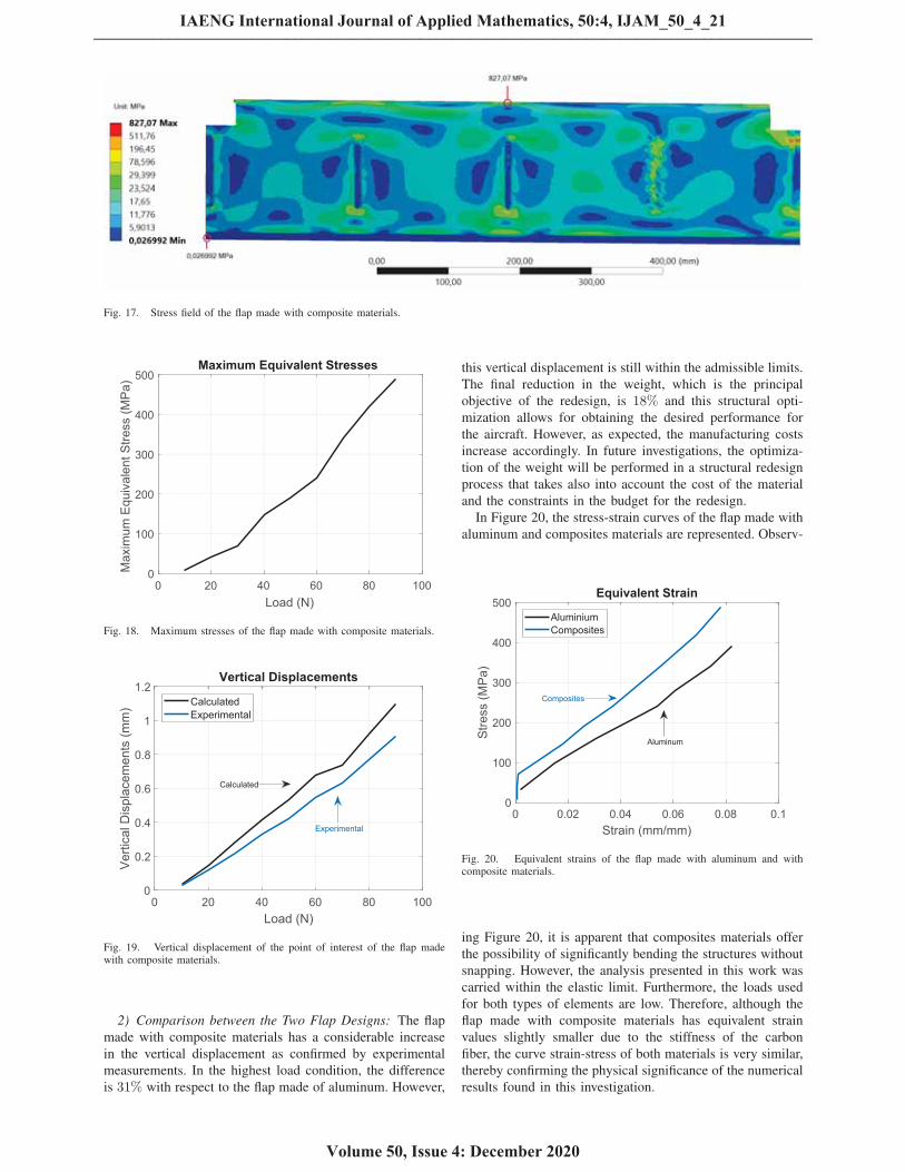
Fig. 17. Stress field of the flap made with composite materials.
0 20 40 60 80 100Load (N)
0
100
200
300
400
500
Max
imum
Equ
ival
ent S
tress
(MPa
)
Maximum Equivalent Stresses
Fig. 18. Maximum stresses of the flap made with composite materials.
0 20 40 60 80 100Load (N)
0
0.2
0.4
0.6
0.8
1
1.2
Verti
cal D
ispl
acem
ents
(mm
)
Vertical Displacements
CalculatedExperimental
Calculated
Experimental
Fig. 19. Vertical displacement of the point of interest of the flap madewith composite materials.
2) Comparison between the Two Flap Designs: The flap
made with composite materials has a considerable increase
in the vertical displacement as confirmed by experimental
measurements. In the highest load condition, the difference
is 31% with respect to the flap made of aluminum. However,
this vertical displacement is still within the admissible limits.
The final reduction in the weight, which is the principal
objective of the redesign, is 18% and this structural opti-
mization allows for obtaining the desired performance for
the aircraft. However, as expected, the manufacturing costs
increase accordingly. In future investigations, the optimiza-
tion of the weight will be performed in a structural redesign
process that takes also into account the cost of the material
and the constraints in the budget for the redesign.
In Figure 20, the stress-strain curves of the flap made with
aluminum and composites materials are represented. Observ-
0 0.02 0.04 0.06 0.08 0.1Strain (mm/mm)
0
100
200
300
400
500
Stre
ss (M
Pa)
Equivalent Strain
AluminiumComposites
Aluminum
Composites
Fig. 20. Equivalent strains of the flap made with aluminum and withcomposite materials.
ing Figure 20, it is apparent that composites materials offer
the possibility of significantly bending the structures without
snapping. However, the analysis presented in this work was
carried within the elastic limit. Furthermore, the loads used
for both types of elements are low. Therefore, although the
flap made with composite materials has equivalent strain
values slightly smaller due to the stiffness of the carbon
fiber, the curve strain-stress of both materials is very similar,
thereby confirming the physical significance of the numerical
results found in this investigation.
IAENG International Journal of Applied Mathematics, 50:4, IJAM_50_4_21
Volume 50, Issue 4: December 2020
______________________________________________________________________________________

V. SUMMARY, CONCLUSIONS, AND FUTURE DIRECTIONS
OF RESEARCH
In general, the research of the authors is concerned with
three main areas of interest pertaining to mechanical engi-
neering, namely multibody dynamics, nonlinear control, and
system identification. Multibody dynamics is focused on the
study of the dynamic behavior of mechanical systems that
comprise rigid and flexible bodies which are constrained
by kinematic joints [89]–[92]. Nonlinear control is focused
on the development of effective control strategies suitable
for controlling mechanical systems described by nonlinear
mathematical models [93]–[96]. System identification is fo-
cused on the determination of appropriate estimations of the
parameters that serve to implement a dynamical model of a
mechanical system [97]–[100]. This paper, on the other hand,
deals with the redesign and optimization of the principal
mechanical components that form the structural parts of an
aircraft.
This research study presents the redesign of two impor-
tant components of a general-aviation single-engine aircraft,
namely the bulkhead and flap structural components. The
performance of these components is evaluated by means
of numerical analysis based on the finite element method
and using experimental verifications. A simple optimization
algorithm is also used for carrying out the structural redesign
of the mechanical components considered in this paper. The
flaps, originally made of aluminum, are redesigned using
composites materials, thereby reducing the weight of the
entire aircraft. In the redesign of the bulkhead, on the other
hand, the use of pre-impregnated fiber carbon is studied. The
redesign and the structural optimization of each mechanical
component are evaluated through a finite element numerical
analysis and by using a numerical optimization procedure.
To this end, finite element models are developed and im-
plemented in a virtual environment since the static analysis
performed by using the finite element method represents an
appropriate numerical technique suitable for addressing and
solving the complex problem of interest for this investigation.
In the finite element analysis performed in this investigation,
the critical points of the structural components were iden-
tified and analyzed with several failure criteria in order to
assess the viability of the material selection considered in
the redesign phase. Furthermore, the quality of the numerical
results obtained from the computational analysis developed
in this work is assessed by using a set of experimental data
available from an industrial partnership project involving
the authors and local companies that manufacture aircraft
components.
In this research work, the static performance of three fun-
damental aeronautical components is analyzed using a finite
element approach. The mechanical components considered
in this study are the bulkhead and two types of flaps. As
demonstrated in this study, these mechanical components are
capable of fully supporting the loading conditions imposed
on the class of aircraft considered in this study. In particular,
the bulkhead represents the principal structural component of
a general-aviation single-engine which is used for supporting
the weight of the engine and the external loads coming from
the landing gear. The flaps, on the other hand, are commonly
used for increasing the lift of the aircraft wings at a given
airspeed. The bulkhead considered in this study is formed
by a stack of prepreg carbon fibers. Two types of flaps
are considered in this paper. The first type of flap is made
of aluminum, while the second type of flap is composed
of carbon fibers. In the static analysis of the flaps, these
mechanical components are tested employing a set of loading
conditions established by using aeronautical correlations.
For this purpose, only a set of vertical forces is assumed
as the externally applied loads, whereas fixed and pinned
conditions due to the presence of bearings are employed
as the boundary conditions. The set of applied forces and
boundary conditions mentioned before are implemented in
finite element models developed by the authors using the
commercial software ANSYS and starting from CAD models
of the mechanical components considered in this work.
The CAD models employed in this investigation are highly
detailed since these models were previously developed in the
context of an industrial partnership agreement signed by the
authors in collaboration with local companies that develop
and manufacture aircraft structural components. Thus, the
main contribution of the finite element analysis performed
in this research work is the assessment of the reliability and
the evaluation of the performance of the structural redesign
carried out for the bulkhead and the flap components of a
general-aviation single-engine aircraft.
Future research works will be devoted to the important
topic of the Integration between the Computer-Aided De-
sign and Analysis (I-CAD-A). Next-generation computer
programs will allow for performing the geometric design,
the simulation of the rigid body motion including large
displacements and finite rotations, and the static and dynamic
analysis of the structural components in a seamless envi-
ronment, thereby enabling the engineers to obtain a robust
design of a machine component that is optimal according
to multiple criteria. The development of this new class of
software requires the use of appropriate analytical techniques
and advanced computational procedures, such as for example
the Absolute Nodal Coordinate Formulation (ANCF) and the
Isogeometric Analysis (IA), that will be the object of future
investigations.
AUTHOR CONTRIBUTIONS
This research paper was principally developed by the first
author (Sergio Andres Ardila-Parra). In the development of
the paper, great support and guide were provided by the
second author (Carmine Maria Pappalardo). The detailed
review carried out by the third author (Octavio Andres
Gonzalez Estrada) and by the fourth author (Domenico
Guida) considerably improved the quality of the work.
REFERENCES
[1] M. A. Jami’in and E. Julianto, “Hierarchical Algorithms of Quasi-Linear ARX Neural Networks for Identification of Nonlinear Sys-tems,” Engineering Letters, vol. 25, no. 3, pp321-328, 2017.
[2] J. Zhang, L. Yu, and L. Ding, “Velocity Feedback Control of SwingPhase for 2-DoF Robotic Leg Driven by Electro-hydraulic ServoSystem,” Engineering Letters, vol. 24, no. 4, pp378-383, 2016.
[3] Q. W. Guo, W. D. Song, M. Gao, and D. Fang, “Advanced GuidanceLaw Design for Trajectory-Corrected Rockets with Canards underSingle Channel Control,” Engineering Letters, vol. 24, no. 4, pp469-477, 2016.
IAENG International Journal of Applied Mathematics, 50:4, IJAM_50_4_21
Volume 50, Issue 4: December 2020
______________________________________________________________________________________

[4] H. Liu and Y. Li, “Safety Evaluation of a Long-Span Steel Trestlewith an Extended Service Term Age in a Coastal Port Based onIdentification of Modal Parameters,” Engineering Letters, vol. 24,no. 1, pp84-92, 2016.
[5] I. I. Lazaro, A. Alvarez, and J. Anzurez, “The Identification ProblemApplied to Periodic Systems Using Hartley Series,” EngineeringLetters, vol. 21, no. 1, pp36-43, 2013.
[6] F. Villecco and A. Pellegrino, “Evaluation of Uncertainties in theDesign Process of Complex Mechanical Systems,” Entropy, vol. 19,no. 9, 475, 2017.
[7] F. Villecco and A. Pellegrino, “Entropic Measure of EpistemicUncertainties in Multibody System Models by Axiomatic Design,”Entropy, vol. 19, no. 7, 291, 2017.
[8] R. Barbagallo, G. Sequenzia, A. Cammarata, S. M. Oliveri, andG. Fatuzzo, “Redesign and multibody simulation of a motorcyclerear suspension with eccentric mechanism,” International Journalon Interactive Design and Manufacturing (IJIDeM), vol. 12, no. 2,pp517-524, 2018.
[9] R. Barbagallo, G. Sequenzia, S. M. Oliveri, and A. Cammarata,“Dynamics of a high-performance motorcycle by an advanced multi-body/control co-simulation,” Proceedings of the Institution of Me-chanical Engineers, Part K: Journal of Multi-body Dynamics, vol.230, no. 2, pp207-221, 2016.
[10] A. Cammarata, “Unified formulation for the stiffness analysis ofspatial mechanisms,” Mechanism and Machine Theory, 105, pp272-284, 2016.
[11] A. Cammarata, “Optimized design of a large-workspace 2-DOFparallel robot for solar tracking systems,” Mechanism and MachineTheory, 83, pp175-186, 2015.
[12] M. Culbreth, Y. Allaneau, and A. Jameson, “High-fidelity optimiza-tion of flapping airfoils and wings,” In: Proceedings of the 29th AIAAApplied Aerodynamics Conference, pp3521, 2011.
[13] R. Citarella and G. Cricrı, “Three-dimensional BEM and FEMsubmodelling in a cracked FML full scale aeronautic panel,” AppliedComposite Materials, vol. 21, no. 3, pp557-577, 2014.
[14] R. Citarella, L. Federico, and A. Cicatiello, “Modal acoustic transfervector approach in a FEM–BEM vibro-acoustic analysis,” Engineer-ing Analysis with Boundary Elements, vol. 31, no. 3, pp248-258,2007.
[15] E. Onate, Structural analysis with the finite element method. Linearstatics: Volume 1: Basis and solids, Springer Science and BusinessMedia, 2013.
[16] E. Onate, Structural analysis with the finite element method. Linearstatics: Volume 2: Beams, plates, and shells, Springer Science andBusiness Media, 2013.
[17] J. T. Katsikadelis, The Boundary Element Method for Engineers andScientists: Theory and Applications, Academic Press, 2016.
[18] K. V. N. Gopal, “Product design for advanced composite materialsin aerospace engineering,” In: Advanced Composite Materials forAerospace Engineering, Elsevier, pp413-428, 2016.
[19] H. T. Helali and M. Grafinger, “The precision of FEM simulationresults compared with theoretical composite layup calculation,” Com-posites Part B: Engineering, 95, pp282-292, 2016.
[20] G. Brown, “The use of composites in aircraft construction,”http://vandaair.com/2014/04/14/the-use-of-composites-in-aircraft-construction, 2014.
[21] S. Rana and R. Fangueiro, Advanced composite materials foraerospace engineering: processing, properties and applications,Woodhead Publishing, 2016.
[22] E. C. Botelho, R. A. Silva, L. C. Pardini, and M. C. Rezende,“A review on the development and properties of continuousfiber/epoxy/aluminum hybrid composites for aircraft structures,” Ma-terials Research, vol. 9, no. 3, pp247-256, 2006.
[23] C. R. Bryant, D. A. McAdams, R. B. Stone, T. Kurtoglu, and M. I.Campbell, “A computational technique for concept generation,” In:Proceedings of the ASME (American Society of Mechanical Engi-neers) 2005 International Design Engineering Technical Conferencesand Computers and Information in Engineering Conference, pp267-276, 2005.
[24] J. Allison, D. Backman, and L. Christodoulou, “Integrated computa-tional materials engineering: a new paradigm for the global materialsprofession,” Jom, vol. 58, no. 11, pp25-27, 2006.
[25] D. Russo, C. Rizzi, “Structural optimization strategies to design greenproducts,” Computers in industry, vol. 65, no. 3, pp470-479, 2014.
[26] C. Soutis, “Carbon fiber reinforced plastics in aircraft construction,”Materials Science and Engineering: A, vol. 412, no. 1-2, pp171-176,2005.
[27] R. D. Buehrle, G. A. Fleming, R. S. Pappa, and F. W. Grosveld,“Finite element model development for aircraft fuselage structures,”2000.
[28] V. Mukhopadhyay, “Structural concepts study of non-circular fuse-lage configurations,” 1996.
[29] E. A. Calado, M. Leite, and A. Silva, “Selecting composite materialsconsidering cost and environmental impact in the early phases ofaircraft structure design,” Journal of Cleaner Production, 186, pp113-122, 2018.
[30] C. Kassapoglou, “Minimum cost and weight design of fuselageframes: Part A: design constraints and manufacturing process char-acteristics,” Composites Part A: Applied Science and Manufacturing,vol. 30, no. 7, pp887-894, 1999.
[31] C. Kassapoglou, ‘Minimum cost and weight design of fuselageframes: Part B: cost considerations, optimization, and results,” Com-posites Part A: Applied Science and Manufacturing, vol. 30, no. 7,pp895-904, 1999.
[32] S. D. Thoppul, J. Finegan, and R. F. Gibson, “Mechanics of me-chanically fastened joints in polymer - Matrix composite structures- A review,” Composites Science and Technology, vol. 69, no. 3-4,pp301-329, 2009.
[33] R. Kaye and M. Heller, “Investigation of shape optimization forthe design of life extension options for an F/A-18 airframe FS 470bulkhead,” The Journal of Strain Analysis for Engineering Design,vol. 35, no. 6, pp493-505, 2000.
[34] T. D. Marusich, S. Usui, and K. J. Marusich, “Finite element mod-eling of part distortion,” In: International Conference on IntelligentRobotics and Applications, Springer, Berlin, Heidelberg, pp329-338,2008.
[35] A. Germaneau, F. Peyruseigt, S. Mistou, P. Doumalin, and J. C.Dupre, “3D mechanical analysis of aeronautical plain bearings: Val-idation of a finite element model from measurement of displacementfields by digital volume correlation and optical scanning tomogra-phy,” Optics and Lasers in Engineering, vol. 48, no. 6, pp676-683,2010.
[36] M. Guida, F. Marulo, “Partial modeling of aircraft fuselage during anemergency crash landing,” Procedia Engineering, 88, pp26-33, 2014.
[37] E. L. Fasanella and K. E. Jackson, “Crash simulation of a verticaldrop test of a B737 fuselage section with auxiliary fuel tank,” 2001.
[38] K. E. Jackson and E. L. Fasanella, “Crash simulation of a verticaldrop test of a B737 fuselage section with overhead bins and luggage,”In: Proceedings of the Third Triennial Aircraft Fire and Cabin SafetyConference, Atlantic City, NJ, pp22-25, 2001.
[39] I. Kumakura, M. Minegishi, K. Iwasaki, H. Shoji, N. Yoshimoto,H. Terada, T. Hayashi, “Vertical drop test of a transport fuselagesection,” SAE Technical Paper, No. 2002-01-2997, 2002.
[40] A. Ghali, A. Neville, and T. G. Brown, Structural Analysis: A UnifiedClassical and Matrix Approach, Crc Press, 2014.
[41] R. E. Melchers and A. T. Beck, Structural reliability analysis andprediction, John Wiley and Sons, 2018.
[42] L. U. Hansen, W. Heinze, and P. Horst, “Blended wing bodystructures in multidisciplinary pre-design,” Structural and Multidis-ciplinary Optimization, vol. 36, no. 1, pp93-106, 2008.
[43] I. V. Ivanov, “Analysis, modelling, and optimization of laminatedglasses as plane beam,” International Journal of Solids and Struc-tures, vol. 43, no. 22-23, pp6887-6907, 2006.
[44] A. Esnaola, B. Elguezabal, J. Aurrekoetxea, I. Gallego, and I. Ulacia,“Optimization of the semi-hexagonal geometry of a composite crushstructure by finite element analysis,” Composites Part B: Engineering,93, pp56-66, 2016.
[45] J. Sliseris, G. Frolovs, K. Rocens, and V. Goremikins, “Optimaldesign of GFRP-plywood variable stiffness plate,” Procedia Engi-neering, 57, pp1060-1069, 2013.
[46] V. Mukhopadhyay, J. Sobieszczanski-Sobieski, I. Kosaka, G. Quinn,and G. N. Vanderpaats, “Analysis, design, and optimization ofnoncylindrical fuselage for blended-wing-body vehicle,” Journal ofAircraft, vol. 41, no. 4, pp925-930, 2004.
[47] R. A. Witik, F. Gaille, R. Teuscher, H. Ringwald, V. Michaud,and J. A. E. Manson, “Economic and environmental assessment ofalternative production methods for composite aircraft components,”Journal of Cleaner Production, 29, pp91-102, 2012.
[48] K. T. Van Den Kieboom, and A. Elham, “Concurrent wing and high-lift system aerostructural optimization,” Structural and Multidisci-plinary Optimization, vol. 57, no. 3, pp947-963, 2018.
[49] J. K. S. Dillinger, T. Klimmek, M. M. Abdalla, and Z. Gurdal, “Stiff-ness optimization of composite wings with aeroelastic constraints,”Journal of Aircraft, vol. 50, no. 4, pp1159-1168, 2013.
[50] O. T. Thomsen and J. R. Vinson, “Analysis and parametric studyof non-circular pressurized sandwich fuselage cross section usinga high-order sandwich theory formulation,” Journal of SandwichStructures and Materials, vol. 3, no. 3, pp220-250, 2001.
[51] D. Liu, H. Lohse-Busch, V. Toropov, C. Huhne, and U. Armani,“Detailed design of a lattice composite fuselage structure by a mixed
IAENG International Journal of Applied Mathematics, 50:4, IJAM_50_4_21
Volume 50, Issue 4: December 2020
______________________________________________________________________________________

optimization method,” Engineering Optimization, vol. 48, no. 10,pp1707-1720, 2016.
[52] L. Krog, A. Tucker, M. Kemp, and R. Boyd, “Topology optimisationof aircraft wing box ribs,” In: Proceeding of the 10th AIAA/ISSMOmultidisciplinary analysis and optimization conference, p. 4481,2004.
[53] R. Arravind, M. Saravanan, R. M. Rijuvan, and D. Vadivel, “Design,analysis and simulation of a composite bulkhead,” In: Proceedingsof the International Conference on Mechanical and Industrial Engi-neering (ICMIE’12) on 16-12-2012, Nagpur, 2005.
[54] T. Wang and J. Maxon, “Application of statistical energy analysis andoptimization in the design of Gulfstream large-cabin aircraft interiorthermal/acoustic package,” In: Proceedings of the INTER-NOISE andNOISE-CON congress and conference proceedings, Institute of NoiseControl Engineering, vol. 2008, no. 7, pp2073-2084, 2008.
[55] S. Ding and X. Zhou, “Structural design and optimization of amorphing wing trailing edge flap,” Aerospace Systems, vol. 1, no.2, pp109-119, 2018.
[56] R. Kienzler and G. Herrmann, “Mechanics in material space: withapplications to defect and fracture mechanics,” Springer Science andBusiness Media, vol. 11, 2012.
[57] R. T. Haftka and Z. Gurdal, “Elements of structural optimization,”Springer Science and Business Media, vol. 11, 2012.
[58] N. V. Queipo, R. T. Haftka, W. Shyy, T. Goel, R. Vaidyanathan, andP. K. Tucker, “Surrogate-based analysis and optimization,” Progressin aerospace sciences, vol. 41, no. 1, pp.1-28, 2005.
[59] R. T. Haftka and R. V. Grandhi, “Structural shape optimization - Asurvey,” Computer methods in applied mechanics and engineering,vol. 57, no. 1, pp91-106, 1986.
[60] R. T. Haftka and B. Prasad, “Optimum structural design with platebending elements-a survey,” AIAA Journal, vol. 19, no. 4, pp517-522,1981.
[61] S. Venkataraman and R. Haftka, “Structural Optimization: What hasMoore’s Law done for us?,” In: 43rd AIAA/ASME/ASCE/AHS/ASCStructures, Structural Dynamics, and Materials Conference, p. 1342,2002.
[62] G. J. Kennedy and J. R. Martins, “A parallel finite-element frame-work for large-scale gradient-based design optimization of high-performance structures,” Finite Elements in Analysis and Design, 87,pp56-73, 2014.
[63] R. P. Henderson, J. R. Martins, and R. E. Perez, “Aircraft conceptualdesign for optimal environmental performance,” The AeronauticalJournal, vol. 116, no. 1175, pp1-22, 2012.
[64] C. M. Pappalardo, M. C. De Simone, and D. Guida, “Multibodymodeling and nonlinear control of the pantograph/catenary system,”Archive of Applied Mechanics, vol. 89, no. 8, pp1589-1626, 2019.
[65] J. R. Martins, J. J. Alonso, and J. J. Reuther, “A coupled-adjointsensitivity analysis method for high-fidelity aero-structural design,”Optimization and Engineering, vol. 6, no. 1, pp33-62, 2005.
[66] A. A. Shabana, Computational Continuum Mechanics, John Wileyand Sons, 2018.
[67] C. M. Pappalardo, T. Wang, and A. A. Shabana, “On the formulationof the planar ANCF triangular finite elements,” Nonlinear Dynamics,vol. 89, no. 2, pp1019-1045, 2017.
[68] C. M. Pappalardo, T. Wang, and A. A. Shabana, “Developmentof ANCF tetrahedral finite elements for the nonlinear dynamics offlexible structures,” Nonlinear Dynamics, vol. 89, no. 4, pp2905-2932, 2017.
[69] C. M. Pappalardo, Z. Zhang, and A. A. Shabana, “Use of independentvolume parameters in the development of new large displacementANCF triangular plate/shell elements,” Nonlinear Dynamics, vol. 91,no. 4, pp2171-2202, 2018.
[70] K. J. Bathe, Finite Element Procedures, Prentice Hall, 2006.
[71] T. J. Hughes, The finite element method: Linear static and dynamicfinite element analysis, Courier Corporation, 2012.
[72] O. C. Zienkiewicz, R. L. Taylor, and R. L. Taylor, The finite elementmethod: Solid mechanics, Volume 2, Butterworth-Heinemann, 2000.
[73] J. Bonet and R. D. Wood, Nonlinear continuum mechanics for finiteelement analysis, Cambridge university press, 1997.
[74] A. A. Shabana, Dynamics of Multibody Systems, Cambridge Uni-versity Press, 2013.
[75] T. Belytschko, W. K. Liu, B. Moran, and K. Elkhodary, Nonlinearfinite elements for continua and structures, John wiley and Sons,2013.
[76] C. M. Pappalardo, “A natural absolute coordinate formulation forthe kinematic and dynamic analysis of rigid multibody systems,”Nonlinear Dynamics, vol. 81, no. 4, pp1841-1869, 2015.
[77] A. A. Shabana, Computational Dynamics, John Wiley and Sons,2009.
[78] P. Sirisalee, G. T. Parks, P. J. Clarkson, and M. F. Ashby, “Anew approach to multi-criteria material selection in engineeringdesign,” In: DS 31, Proceedings of ICED 03, the 14th InternationalConference on Engineering Design, Stockholm, pp451-452, 2003.
[79] R. L. Keeney and H. Raiffa, Decisions with Multiple Objectives:Preferences and Value Trade-Offs, Cambridge University Press, 1993.
[80] M. F. Ashby, “Multi-objective optimization in material design andselection,” Acta materialia, vol. 48, no. 1, pp359-369, 2000.
[81] P. E. Illman and G. E. Gailey, The pilot’s handbook of aeronauticalknowledge, McGraw-Hill, 2000.
[82] E. J. Barbero, Finite element analysis of composite materials usingANSYS R©, CRC press, 2013.
[83] H. Laith, H. Kareem, N. Natik, ANSYS Workbench for mechanicalengineering: A step by step to learn ANSYS Workbench, 2015.
[84] M. R. Hatch, Vibration simulation using MATLAB and ANSYS,Chapman and Hall-CRC, 2000.
[85] H. H. Lee, Finite Element Simulations with ANSYS Workbench 18,SDC Publications, 2018.
[86] T. Stolarski, Y. Nakasone, S. Yoshimoto, Engineering analysis withANSYS software, Butterworth-Heinemann, 2018.
[87] M. J. Hinton, A. S. Kaddour, and P. D. Soden, Failure criteria infibre reinforced polymer composites: the world-wide failure exercise,Elsevier, 2004.
[88] R. M. Jones, Mechanics of composite materials, CRC press, 2018.[89] M. C. De Simone, S. Russo, Z. B. Rivera, and D. Guida, “Multibody
Model of a UAV in Presence of Wind Fields,” Proceedings - 2017International Conference on Control, Artificial Intelligence, Roboticsand Optimization, ICCAIRO 2017, 2018-January, pp83-88, 2018.
[90] M. C. De Simone, Z. B. Rivera, and D. Guida, “A New Semi-ActiveSuspension System for Racing Vehicles,” FME Transactions, vol. 45,no. 4, pp579, 2017.
[91] M. C. De Simone and D. Guida, “On the Development of aLow Cost Device for Retrofitting Tracked Vehicles for AutonomousNavigation,” Proceedings of the XXIII Conference of the ItalianAssociation of Theoretical and Applied Mechanics (AIMETA 2017),4-7 Spetember 2017, Salerno, Italy, 2017.
[92] A. Ruggiero, M. C. De Simone, D. Russo, and D. Guida, “Soundpressure measurement of orchestral instruments in the concert hallof a public school,” International Journal of Circuits, Systems andSignal Processing, 10, pp75-812, 2016.
[93] M. C. De Simone and D. Guida, “Dry Friction Influence onStructure Dynamics,” COMPDYN 2015 - 5th ECCOMAS ThematicConference on Computational Methods in Structural Dynamics andEarthquake Engineering, pp4483-4491, 2015.
[94] A. Ruggiero, S. Affatato, M. Merola, and M. C. De Simone, “FEManalysis of metal on UHMWPE total hip prosthesis during normalwalking cycle,” Proceedings of the XXIII Conference of The ItalianAssociation of Theoretical and Applied Mechanics (AIMETA 2017),Salerno, Italy; 4-7 September 2017, (2017), 2017.
[95] M. C. De Simone, Z. B. Rivera, and D. Guida, “Obstacle AvoidanceSystem for Unmanned Ground Vehicles by using Ultrasonic Sensors,”Machines, vol. 6, no. 2, 18, 2018.
[96] V. Iannone and M. C. De Simone, “Modelling of a DC Gear Motor forFeed-Forward Control Law Design for Unmanned Ground Vehicles,”Actuators, In press, 2018.
[97] A. Quatrano, M. C. De Simone, Z. B. Rivera, and D. Guida, “Devel-opment and Implementation of a Control System for a RetrofittedCNC Machine by Using Arduino,” FME Transactions, vol. 45,pp578-584, 2017.
[98] M. C. De Simone and D. Guida, “Modal Coupling in Presence ofDry Friction,” Machines, vol. 6, no.1, 8, 2018.
[99] M. C. De Simone and D. Guida, “Identification and control ofa Unmanned Ground Vehicle by using Arduino,” UPB ScientificBulletin, Series D: Mechanical Engineering, vol. 80, no. 1, pp141-154, 2018.
[100] M. C. De Simone, Z. B. Rivera, and D. Guida, “Finite Element Anal-ysis on Squeal-Noise in Railway Applications,” FME Transactions,vol. 46, no. 1, pp93-100, 2018.
IAENG International Journal of Applied Mathematics, 50:4, IJAM_50_4_21
Volume 50, Issue 4: December 2020
______________________________________________________________________________________