Embed Size (px)
Citation preview
ANALYSIS AND REDESIGN OF W- TYPE RADIANT TUBE USING FINITE ELEMENT
METHOD
INTERNAL GUIDE:
Mr.M.Varatharajulu,B.E., M.B.A (Asst. Professor),
Dept. Of Mechanical Engg.
PRESENT BY
M.Akbar Ali
A.HajaSheikAlavuden
V .Saravanan
M .Venkateshwaran
EXTERNAL GUIDE:
Mr. A. Karuppiah. M.EManagerCold Mill (SSTP)BHEL. (Trichy)

To analyze and to find out the failure causes of the radiant tube.
Provide solution for the failure of radiant Tube.
Comparing the solution with the existing design.
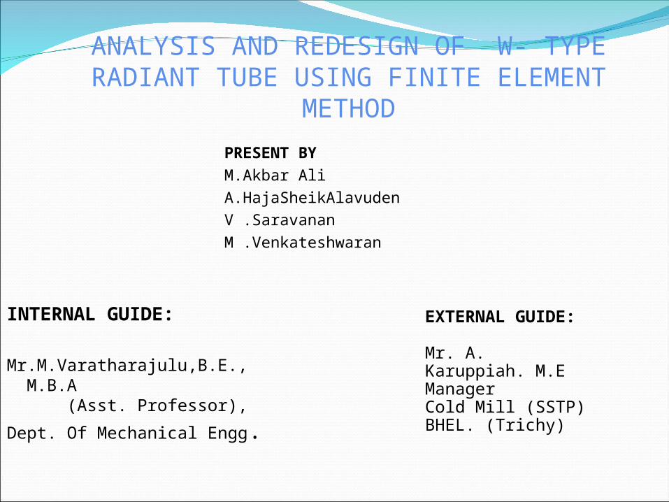
INTRODUTION ABOUT RADIANT TUBE
Radiant tubes are heat transfer mountings. Gases by convection and radiation transfers heat to the
radiant tube. The heated tube transfers energy to the furnace, by means
of convection and radiative heat transfer. There are three types of radiant tube P-type ,W-type& U-
type. Our project is concerned with w-type radiant tube. Material of the radiant tubes are nickel chrome steel.

PROBLEM DESCRIPTON
Radiant tubes are designed to operate at 960°C; the furnace temperature is maintained between 700°C and 1100°C by a design requirement based on the tube thickness.
Due to the uneven heating, the radiant tubes were frequently damaged after their rated service.
In general, the damage style of a number of the tubes is almost the same. The failure mode of the tubes appeared to be in the surface of the tube, about 65–90 cm from the burner-mounting flange.
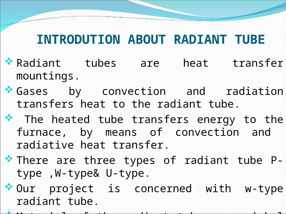
METHODOLOGYThe analysis can be carried out using ANSYS softwareIn general, there are three steps in the development of
a finite element model.Developing a geometrical model, selecting an
element, determining material properties and finally converting the geometrical model to a finite element model by griding.
Applying boundary and initial conditions, loading and performing calculations based on the model.
Extracting results.

Contd.
Modeling of the radiant tube was done by using Pro-e software.The model is imported to the ANSYS and imported model is
meshed. And finally using ANSYS software, the analysis of the radiant
tube was done. The results were obtained for various parameters
like temperature distribution, equivalent stress and total deformation.
The results obtained for suggested model were compared with the existing model.


Contd.


RESULTS & DISCUSSION
S.NoApproximate Distance from
burner-mounting flange (mm)
1 0 - 300
2 300 - 600
3 600 - 1000
4 1000 - 1500
5 1500 - 2500
6 2500 - 4500
7 4500 - 5000
8 5000 - 5500
9 5500 - 6000
10 6000 - 6600

Suggestion IIt is suggested to increase the thickness of the wall in the Radiant tube.Suggestion IIIt is suggested to change the material properties, which will withstand the load against the exiting failure.


Observation From the above charts it is observed that the
temperature distribution, equivalent stress and the total deformation are high at the critical region in all the cases.
The suggestion II model exhibits very low stress and deformation compared to other two models.

Material ComparisonExisting material properties Innovated material properties Reason and cause
Elements / Name of the material
DIN17456 (STD) SA 106 Grade A.
C 0.35 to 0.55% 0.35To reduce the hardenability
Si 1.0 to 2.0% 1.2To increase the toughness
and strength at high temperature
Mn ≤ 1.5% 1.5To increase the resistance
to cracking at high temperature
P 0.040 % 0.040To keep the same
weldability
S 0.030 % 0.030To keep the impact
toughness
Cr 27.0 to 30.0 % 30.00To increase the corrosion
resistance at high temperature
Ni 47.0 to 50.0 % 50.00 To increase the strength
Mo ≤ 0.05% 0.05To increase the high temperature tensile
strength
W 4.0 to 6.0 % 6To withstand the high
temperature
Fe Remaining Remaining

Conclusion.Radiant tubes are designed to operate at 960°C; but the furnace
temperature is required maintained between 700°C and 1100°C, so it is required to change the material of the radiant tube.
Analysis of the radiant tube carried out using ANSYS WORKBENCH Software
Results had been obtained for Temperature distribution, Equivalent Stress and for Total deformation for different models.
Graphs have been plotted between Temperature distribution and distance, Equivalent stress and distance and between total deformation and distance for three different models.

Contd.Compared to the existing model, the suggested model I is
found to have 21.05% lesser stress and 21.05% lesser total deformation.
Compared to existing model suggested model II have 34.21% lesser stress and 31.24% lesser deformation.
By this analysis it is found that the suggested models have higher strength and higher temperature withstanding capability than the existing model.
It is suggested that to use model II for the effective use without fail for the longer period than the other two models.