Embed Size (px)
Citation preview
Nationaal Lucht- en Ruimtevaartlaboratorium
National Aerospace Laboratory NLR
NLR-TP-2013-197
High and low fidelity finite element modelling in aircraft composite fuselage structural analysis and optimisation
W.J. Vankan, B.A.T. Noordman and K. Kueres

Nationaal Lucht- en RuimtevaartlaboratoriumNational Aerospace Laboratory NLR
Anthony Fokkerweg 2P.O. Box 905021006 BM AmsterdamThe NetherlandsTelephone +31 (0)88 511 31 13Fax +31 (0)88 511 32 10www.nlr.nl
UNCLASSIFIED
Executive summary
UNCLASSIFIED
Nationaal Lucht- en Ruimtevaartlaboratorium
National Aerospace Laboratory NLR
This report is based on a full paper presented at the 5th European Conference for Aeronautics and Space Sciences, EUCASS2013, Munich, Germany, July 1-5, 2013.
Report no. NLR-TP-2013-197 Author(s) W.J. Vankan B.A.T. Noordman K. Kueres Report classification UNCLASSIFIED Date April 2014 Knowledge area(s) Computational Mechanics and Simulation Technology Collaborative Engineering and Design Descriptor(s) finite element model sub-model barrel panel buckling
High and low fidelity finite element modelling in aircraft composite fuselage structural analysis and optimisation
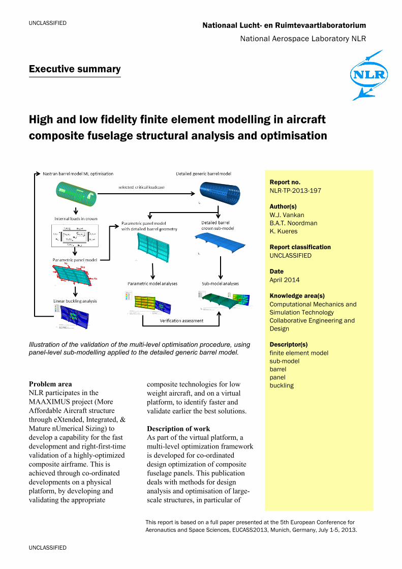
Illustration of the validation of the multi-level optimisation procedure, using panel-level sub-modelling applied to the detailed generic barrel model.
Problem area NLR participates in the MAAXIMUS project (More Affordable Aircraft structure through eXtended, Integrated, & Mature nUmerical Sizing) to develop a capability for the fast development and right-first-time validation of a highly-optimized composite airframe. This is achieved through co-ordinated developments on a physical platform, by developing and validating the appropriate
composite technologies for low weight aircraft, and on a virtual platform, to identify faster and validate earlier the best solutions. Description of work As part of the virtual platform, a multi-level optimization framework is developed for co-ordinated design optimization of composite fuselage panels. This publication deals with methods for design analysis and optimisation of large-scale structures, in particular of
UNCLASSIFIED
UNCLASSIFIED
High and low fidelity finite element modelling in aircraft composite fuselage structural analysis and optimisation
Nationaal Lucht- en Ruimtevaartlaboratorium, National Aerospace Laboratory NLR Anthony Fokkerweg 2, 1059 CM Amsterdam, P.O. Box 90502, 1006 BM Amsterdam, The Netherlands Telephone +31 88 511 31 13, Fax +31 88 511 32 10, www.nlr.nl
composite fuselage barrels. Relatively coarse finite element models were used in a previous study for barrel and panel level analyses in the optimisation process. This study considers high-fidelity finite element models for a verification of the local loading condition in the barrel by the coarse models. The advantage is the more accurate representation of these high-fidelity models. On the other hand, it is expected that their application in the optimisation process is difficult due to the complexity and computational cost of these models. Results and conclusions The accuracy of the panel level buckling analysis as executed in the optimisation methodology with the parametric panel model is limited when compared to the buckling results as obtained with the high fidelity panel sub-model. The stress and strain distributions as obtained from static analyses, however, showed reasonable correspondence between the coarse parametric panel model and the high fidelity panel sub-model. The different results are mainly due to the differences in boundary conditions and loading between the models. The buckling response is much more sensitive to
these differences, e.g. the rotations of the edges of skin, stringers and frames that are fixed in the parametric model whereas in the panel sub-model kinematic constraints are applied to these edges. Applicability The high fidelity barrel model and panel sub-model could be used in the optimisation methodology instead of the low fidelity barrel global finite element model and the parametric panel model. However, model complexity and computational cost would also increase significantly (e.g. 25e6 and 5e5 degrees of freedom, instead of the 24e3 and 40e3 degrees of freedom in the barrel global finite element model and the parametric panel model). Also the panel sub-model analysis, with appropriate boundary conditions (i.e. prescribed displacements), should be re-defined for each location on the barrel and for each load case. Therefore we consider the current approach in the optimisation methodology, based on the low fidelity barrel and panel models, as practically more feasible and reasonably accurate, especially for static stress simulation.
Nationaal Lucht- en Ruimtevaartlaboratorium
National Aerospace Laboratory NLR
NLR-TP-2013-197
High and low fidelity finite element modelling in
aircraft composite fuselage structural analysis
and optimisation
W.J. Vankan, B.A.T. Noordman and K. Kueres1
1 Dassault Systemes UK Limited
This report is based on a full paper presented at the 5th European Conference for Aeronautics and Space
Sciences, EUCASS2013, Munich, Germany, July 1-5, 2013.
The contents of this report may be cited on condition that full credit is given to NLR and the authors.
This publication has been refereed by the Advisory Committee AEROSPACE VEHICLES.
Customer National Aerospace Laboratory NLR
Contract number -----
Owner NLR
Division NLR Aerospace Vehicles
Distribution Unlimited
Classification of title Unclassified
April 2014
Approved by:
Author
W.J. Vankan
Reviewer
A.J. de Wit
Managing department
A.A. ten Dam
Date: Date: Date:


NLR-TP-2013-197
3
Summary
The present paper deals with methods for design analysis and optimisation of large-scale structures, in particular of composite fuselage barrels. Relatively coarse finite element models were used in a previous study for barrel and panel level analyses in the optimisation process. This study considers high-fidelity finite element models for a verification of the local loading condition in the barrel by the coarse models. In spite of the much more accurate representation of the high-fidelity models, it is expected that the complexity and computational cost of these models will hamper their application in the optimisation process.
NLR-TP-2013-197
4
Contents
Abbreviations 5
1 Introduction 7
2 Multi-level optimisation of fuselage barrel structures 8
2.1 The barrel level GFEM 8 2.2 Parametric panel level DFEM 9
3 Hifi structural fuselage models 11
4 Hifi barrel model load case and analysis 14
5 Hifi panel level sub-model analyses 15
6 Parametric panel model analyses 17
7 Panel level assessments and verifications 19
8 Conclusions and discussion 24
References 25
Acknowledgements 25
NLR-TP-2013-197
5
Abbreviations
ACIS ABAQUS file format AIF Airbus Industry – France CAD Computer aided Design CPU Central processing Unit DFEM Detailed Finite Element Model DOE Design Of Experiment DOF Degree of freedom DV Design Variable Eii, Gij linear elastic stiffness constants FEA Finite Element Analysis FEA Finite Element Model GFEM Global Finite Element Model G Giga Fx/y/z Force in x/y/z direction Fn/t/z Free body force components in the normal / tangential / vertical direction IT Information Technology k kilo LC Load Case Pa Pascal [N/mm2] PCOMP NASTRAN composite properties PSHELL NASTRAN shell properties MAAXIMUS More Affordable Aircraft through eXtended, Integrated and Mature
nUmerical Sizing MOE Multi level Optimization Engine MLF Multi level Framework mm millimeter Mx/y/z Moment about x/y/z axis Mn/t/z Free body moment components about the normal / tangential / vertical axes N Newton NLR National Aerospace Laboratory Nx panel edge compression/tension load intensity in stringer direction Nxy panel edge shear load intensity Ny panel edge compression/tension load intensity in frame direction RBE2 NASTRAN coupling constraint SC8R ABAQUS continuum shell element

NLR-TP-2013-197
6
SP Sub Project STEP Standard for the Exchange of Product Data WP Work Package
NLR-TP-2013-197
7
1 Introduction
In the past decades the use of carbon fibre reinforced composite materials on commercial aircraft has been gradually growing, reaching levels of up to about 50% of the structural weight of current state of the art aircraft like the Boeing B787 and the Airbus A350. The advantages offered by these materials are multiple, such as allowing for the design of more integrated structures, yielding lighter and stiffer structures and requiring less maintenance than the traditional metallic structures [1]. In the design analysis and optimisation of primary aircraft structures the focus is usually on the sizing of structural design variables that represent the local thin-wall properties of the structure, like skin thicknesses and stringer dimensions [2]. The increasing use of composite materials in these primary aircraft structures requires that the design analysis and optimisation methods that are used for these structures take into account the specific properties of these materials. For example for structural design and weight optimisation, both the structural geometrical configuration parameters and the composite properties have to be taken into account. These composite properties typically include ply level material properties and laminate stacking sequences, leading to a design problem with both continuous design parameters e.g. for geometric variables like stiffener dimensions, and discrete design parameters e.g. for ply orientations and laminate thicknesses. Dedicated optimisation methods have been developed for that, which are however often applied to smaller scale structures such as fuselage panels [3] and not to the complete fuselage structure. We have been investigating methods for design analysis and optimisation of large scale structures, in particular of a composite fuselage barrel. Efficient simplified representations of the composite parameters are considered in these methods to avoid discrete design parameters. An optimisation methodology was developed where global barrel level structural optimisations are combined with buckling failure constraints coming from more detailed panel level structural optimisations [4]. Design analyses are based on relatively coarse finite element (FE) models of different detail for the different levels and computational efficiency is achieved by exploitation of various surrogate modelling methods and efficient optimisation strategies [5] that were implemented in Matlab [6]. Instead of the relatively coarse FE models that were previously used for the barrel and panel level analyses [4], the present study makes use of much more high-fidelity (hifi) FE models in order to examine the verification of the representation of the local loading condition in the barrel by the panel level FE model. This is achieved by sub-model extraction of a panel level model from the hifi barrel FE model and evaluation of the sub-model buckling response in comparison to the response of the coarse panel level FE model.
NLR-TP-2013-197
8
2 Multi-level optimisation of fuselage barrel structures
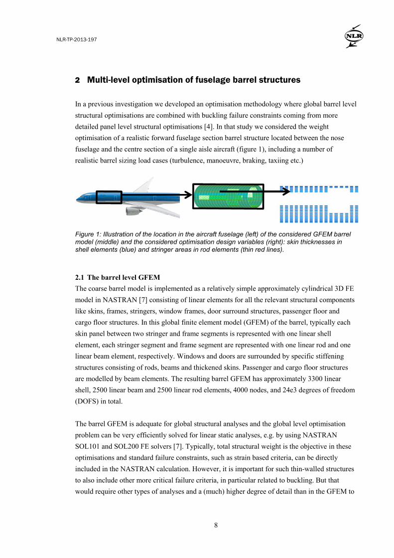
In a previous investigation we developed an optimisation methodology where global barrel level structural optimisations are combined with buckling failure constraints coming from more detailed panel level structural optimisations [4]. In that study we considered the weight optimisation of a realistic forward fuselage section barrel structure located between the nose fuselage and the centre section of a single aisle aircraft (figure 1), including a number of realistic barrel sizing load cases (turbulence, manoeuvre, braking, taxiing etc.)
Figure 1: Illustration of the location in the aircraft fuselage (left) of the considered GFEM barrel model (middle) and the considered optimisation design variables (right): skin thicknesses in shell elements (blue) and stringer areas in rod elements (thin red lines). 2.1 The barrel level GFEM The coarse barrel model is implemented as a relatively simple approximately cylindrical 3D FE model in NASTRAN [7] consisting of linear elements for all the relevant structural components like skins, frames, stringers, window frames, door surround structures, passenger floor and cargo floor structures. In this global finite element model (GFEM) of the barrel, typically each skin panel between two stringer and frame segments is represented with one linear shell element, each stringer segment and frame segment are represented with one linear rod and one linear beam element, respectively. Windows and doors are surrounded by specific stiffening structures consisting of rods, beams and thickened skins. Passenger and cargo floor structures are modelled by beam elements. The resulting barrel GFEM has approximately 3300 linear shell, 2500 linear beam and 2500 linear rod elements, 4000 nodes, and 24e3 degrees of freedom (DOFS) in total. The barrel GFEM is adequate for global structural analyses and the global level optimisation problem can be very efficiently solved for linear static analyses, e.g. by using NASTRAN SOL101 and SOL200 FE solvers [7]. Typically, total structural weight is the objective in these optimisations and standard failure constraints, such as strain based criteria, can be directly included in the NASTRAN calculation. However, it is important for such thin-walled structures to also include other more critical failure criteria, in particular related to buckling. But that would require other types of analyses and a (much) higher degree of detail than in the GFEM to
NLR-TP-2013-197
9
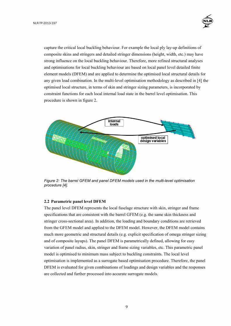
capture the critical local buckling behaviour. For example the local ply lay-up definitions of composite skins and stringers and detailed stringer dimensions (height, width, etc.) may have strong influence on the local buckling behaviour. Therefore, more refined structural analyses and optimisations for local buckling behaviour are based on local panel level detailed finite element models (DFEM) and are applied to determine the optimised local structural details for any given load combination. In the multi-level optimisation methodology as described in [4] the optimised local structure, in terms of skin and stringer sizing parameters, is incorporated by constraint functions for each local internal load state in the barrel level optimisation. This procedure is shown in figure 2.
Figure 2: The barrel GFEM and panel DFEM models used in the multi-level optimisation procedure [4]. 2.2 Parametric panel level DFEM The panel level DFEM represents the local fuselage structure with skin, stringer and frame specifications that are consistent with the barrel GFEM (e.g. the same skin thickness and stringer cross-sectional area). In addition, the loading and boundary conditions are retrieved from the GFEM model and applied to the DFEM model. However, the DFEM model contains much more geometric and structural details (e.g. explicit specification of omega stringer sizing and of composite layups). The panel DFEM is parametrically defined, allowing for easy variation of panel radius, skin, stringer and frame sizing variables, etc. This parametric panel model is optimised to minimum mass subject to buckling constraints. The local level optimisation is implemented as a surrogate based optimisation procedure. Therefore, the panel DFEM is evaluated for given combinations of loadings and design variables and the responses are collected and further processed into accurate surrogate models.
NLR-TP-2013-197
10
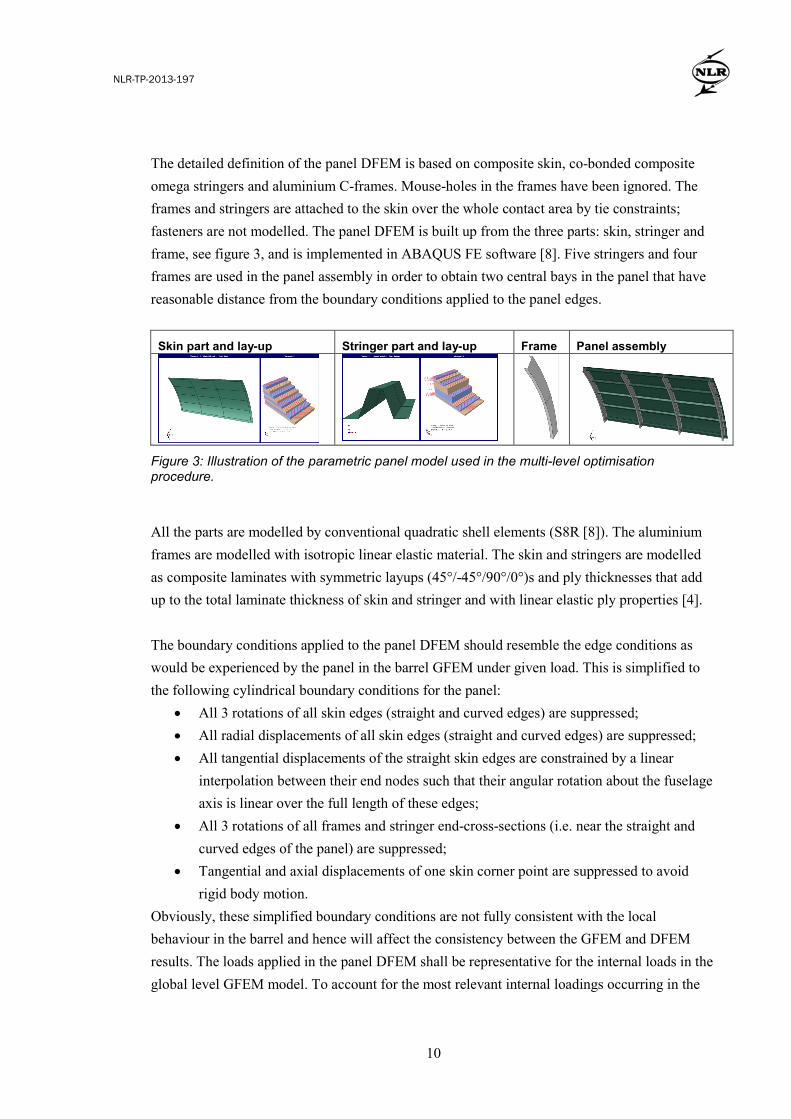
The detailed definition of the panel DFEM is based on composite skin, co-bonded composite omega stringers and aluminium C-frames. Mouse-holes in the frames have been ignored. The frames and stringers are attached to the skin over the whole contact area by tie constraints; fasteners are not modelled. The panel DFEM is built up from the three parts: skin, stringer and frame, see figure 3, and is implemented in ABAQUS FE software [8]. Five stringers and four frames are used in the panel assembly in order to obtain two central bays in the panel that have reasonable distance from the boundary conditions applied to the panel edges.
Skin part and lay-up Stringer part and lay-up Frame Panel assembly
Figure 3: Illustration of the parametric panel model used in the multi-level optimisation procedure. All the parts are modelled by conventional quadratic shell elements (S8R [8]). The aluminium frames are modelled with isotropic linear elastic material. The skin and stringers are modelled as composite laminates with symmetric layups (45°/-45°/90°/0°)s and ply thicknesses that add up to the total laminate thickness of skin and stringer and with linear elastic ply properties [4]. The boundary conditions applied to the panel DFEM should resemble the edge conditions as would be experienced by the panel in the barrel GFEM under given load. This is simplified to the following cylindrical boundary conditions for the panel:
• All 3 rotations of all skin edges (straight and curved edges) are suppressed; • All radial displacements of all skin edges (straight and curved edges) are suppressed; • All tangential displacements of the straight skin edges are constrained by a linear
interpolation between their end nodes such that their angular rotation about the fuselage axis is linear over the full length of these edges;
• All 3 rotations of all frames and stringer end-cross-sections (i.e. near the straight and curved edges of the panel) are suppressed;
• Tangential and axial displacements of one skin corner point are suppressed to avoid rigid body motion.
Obviously, these simplified boundary conditions are not fully consistent with the local behaviour in the barrel and hence will affect the consistency between the GFEM and DFEM results. The loads applied in the panel DFEM shall be representative for the internal loads in the global level GFEM model. To account for the most relevant internal loadings occurring in the
NLR-TP-2013-197
11
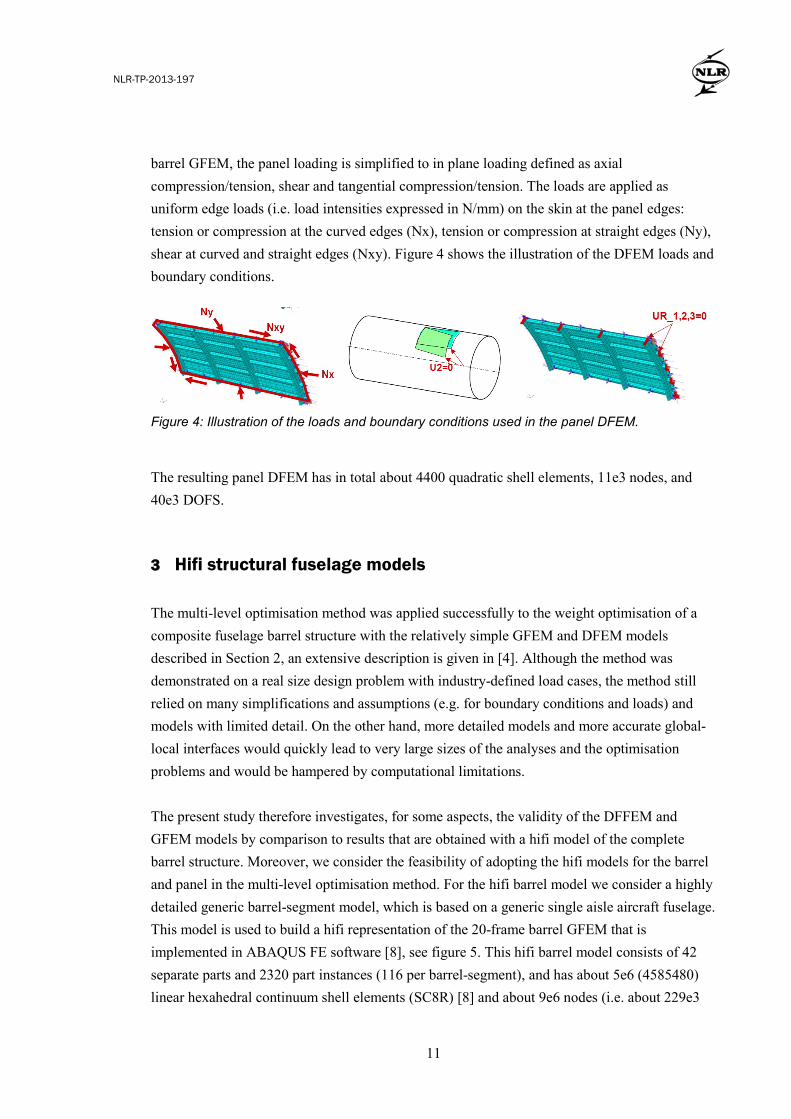
barrel GFEM, the panel loading is simplified to in plane loading defined as axial compression/tension, shear and tangential compression/tension. The loads are applied as uniform edge loads (i.e. load intensities expressed in N/mm) on the skin at the panel edges: tension or compression at the curved edges (Nx), tension or compression at straight edges (Ny), shear at curved and straight edges (Nxy). Figure 4 shows the illustration of the DFEM loads and boundary conditions.
Figure 4: Illustration of the loads and boundary conditions used in the panel DFEM. The resulting panel DFEM has in total about 4400 quadratic shell elements, 11e3 nodes, and 40e3 DOFS. 3 Hifi structural fuselage models
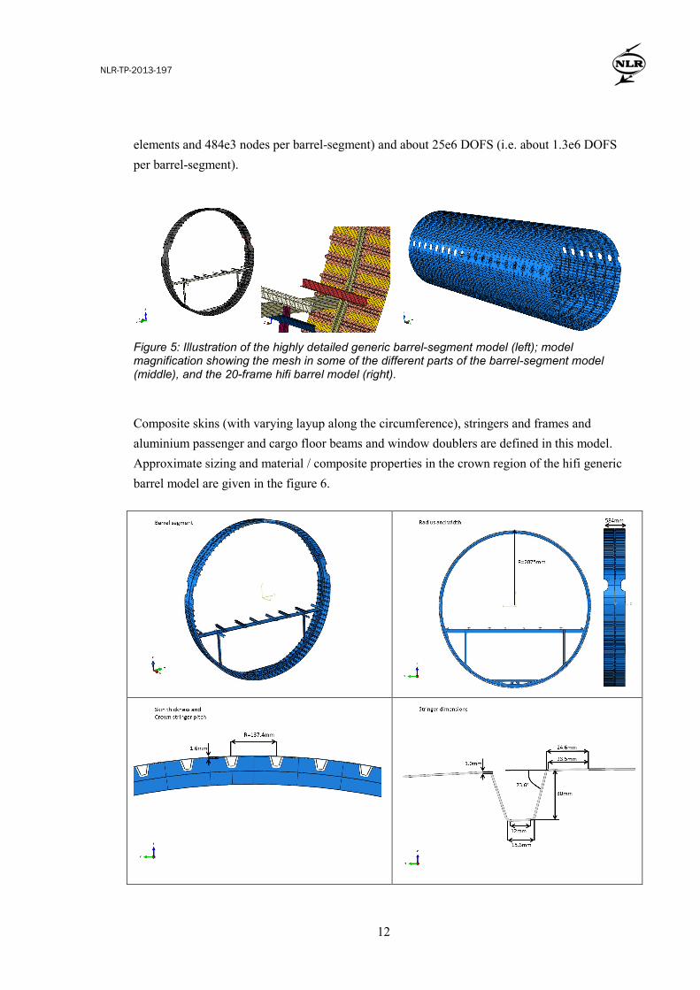
The multi-level optimisation method was applied successfully to the weight optimisation of a composite fuselage barrel structure with the relatively simple GFEM and DFEM models described in Section 2, an extensive description is given in [4]. Although the method was demonstrated on a real size design problem with industry-defined load cases, the method still relied on many simplifications and assumptions (e.g. for boundary conditions and loads) and models with limited detail. On the other hand, more detailed models and more accurate global-local interfaces would quickly lead to very large sizes of the analyses and the optimisation problems and would be hampered by computational limitations. The present study therefore investigates, for some aspects, the validity of the DFFEM and GFEM models by comparison to results that are obtained with a hifi model of the complete barrel structure. Moreover, we consider the feasibility of adopting the hifi models for the barrel and panel in the multi-level optimisation method. For the hifi barrel model we consider a highly detailed generic barrel-segment model, which is based on a generic single aisle aircraft fuselage. This model is used to build a hifi representation of the 20-frame barrel GFEM that is implemented in ABAQUS FE software [8], see figure 5. This hifi barrel model consists of 42 separate parts and 2320 part instances (116 per barrel-segment), and has about 5e6 (4585480) linear hexahedral continuum shell elements (SC8R) [8] and about 9e6 nodes (i.e. about 229e3
NLR-TP-2013-197
12
elements and 484e3 nodes per barrel-segment) and about 25e6 DOFS (i.e. about 1.3e6 DOFS per barrel-segment).
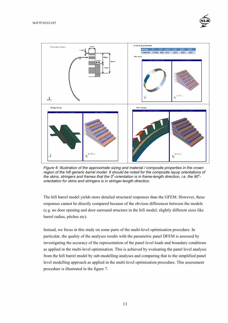
Figure 5: Illustration of the highly detailed generic barrel-segment model (left); model magnification showing the mesh in some of the different parts of the barrel-segment model (middle), and the 20-frame hifi barrel model (right). Composite skins (with varying layup along the circumference), stringers and frames and aluminium passenger and cargo floor beams and window doublers are defined in this model. Approximate sizing and material / composite properties in the crown region of the hifi generic barrel model are given in the figure 6.
NLR-TP-2013-197
13
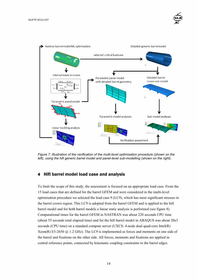
Figure 6: Illustration of the approximate sizing and material / composite properties in the crown region of the hifi generic barrel model. It should be noted for the composite layup orientations of the skins, stringers and frames that the 0o-orientation is in frame-length direction, i.e. the 90o-orientation for skins and stringers is in stringer-length direction. The hifi barrel model yields more detailed structural responses than the GFEM. However, these responses cannot be directly compared because of the obvious differences between the models (e.g. no door opening and door surround structure in the hifi model; slightly different sizes like barrel radius, pitches etc). Instead, we focus in this study on some parts of the multi-level optimisation procedure. In particular, the quality of the analyses results with the parametric panel DFEM is assessed by investigating the accuracy of the representation of the panel level loads and boundary conditions as applied in the multi-level optimisation. This is achieved by evaluating the panel level analysis from the hifi barrel model by sub-modelling analyses and comparing that to the simplified panel level modelling approach as applied in the multi-level optimisation procedure. This assessment procedure is illustrated in the figure 7.
NLR-TP-2013-197
14
Figure 7: Illustration of the verification of the multi-level optimisation procedure (shown on the left), using the hifi generic barrel model and panel-level sub-modelling (shown on the right).
4 Hifi barrel model load case and analysis
To limit the scope of this study, the assessment is focused on an appropriate load case. From the 15 load cases that are defined for the barrel GFEM and were considered in the multi-level optimisation procedure we selected the load case 9 (LC9), which has most significant stresses in the barrel crown region. This LC9 is adopted from the barrel GFEM and is applied to the hifi barrel model and for both barrel models a linear static analysis is performed (see figure 8). Computational times for the barrel GFEM in NASTRAN was about 220 seconds CPU time (about 55 seconds total elapsed time) and for the hifi barrel model in ABAQUS was about 20e3 seconds (CPU time) on a standard compute server (UXCS: 4-node dual quad-core Intel(R) Xeon(R) E5-2650 @ 1.2 GHz). The LC9 is implemented as forces and moments on one side of the barrel and fixations on the other side. All forces, moments and fixations are applied in central reference points, connected by kinematic coupling constraints to the barrel edges.
NLR-TP-2013-197
15
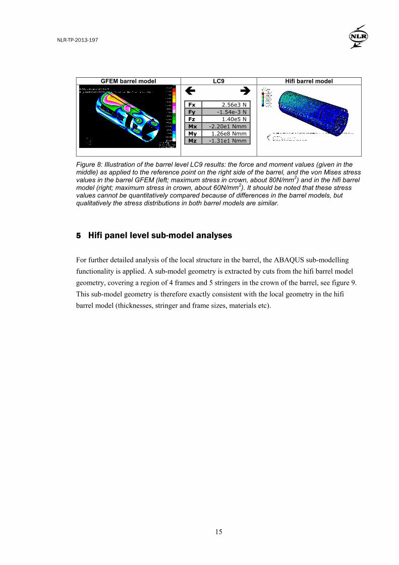
Figure 8: Illustration of the barrel level LC9 results: the force and moment values (given in the middle) as applied to the reference point on the right side of the barrel, and the von Mises stress values in the barrel GFEM (left; maximum stress in crown, about 80N/mm2) and in the hifi barrel model (right; maximum stress in crown, about 60N/mm2). It should be noted that these stress values cannot be quantitatively compared because of differences in the barrel models, but qualitatively the stress distributions in both barrel models are similar.
GFEM barrel model LC9 Hifi barrel model
Fx 2.56e3 N Fy -1.54e-3 N Fz 1.40e5 N Mx -2.20e1 Nmm My 1.26e8 Nmm Mz -1.31e1 Nmm
5 Hifi panel level sub-model analyses
For further detailed analysis of the local structure in the barrel, the ABAQUS sub-modelling functionality is applied. A sub-model geometry is extracted by cuts from the hifi barrel model geometry, covering a region of 4 frames and 5 stringers in the crown of the barrel, see figure 9. This sub-model geometry is therefore exactly consistent with the local geometry in the hifi barrel model (thicknesses, stringer and frame sizes, materials etc).
NLR-TP-2013-197
16
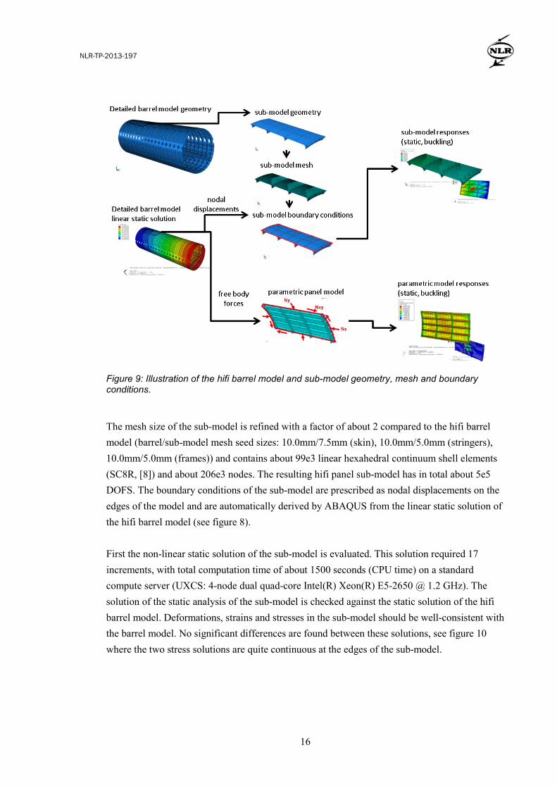
Figure 9: Illustration of the hifi barrel model and sub-model geometry, mesh and boundary conditions.
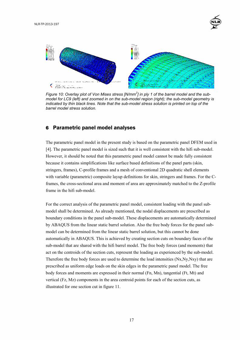
The mesh size of the sub-model is refined with a factor of about 2 compared to the hifi barrel model (barrel/sub-model mesh seed sizes: 10.0mm/7.5mm (skin), 10.0mm/5.0mm (stringers), 10.0mm/5.0mm (frames)) and contains about 99e3 linear hexahedral continuum shell elements (SC8R, [8]) and about 206e3 nodes. The resulting hifi panel sub-model has in total about 5e5 DOFS. The boundary conditions of the sub-model are prescribed as nodal displacements on the edges of the model and are automatically derived by ABAQUS from the linear static solution of the hifi barrel model (see figure 8). First the non-linear static solution of the sub-model is evaluated. This solution required 17 increments, with total computation time of about 1500 seconds (CPU time) on a standard compute server (UXCS: 4-node dual quad-core Intel(R) Xeon(R) E5-2650 @ 1.2 GHz). The solution of the static analysis of the sub-model is checked against the static solution of the hifi barrel model. Deformations, strains and stresses in the sub-model should be well-consistent with the barrel model. No significant differences are found between these solutions, see figure 10 where the two stress solutions are quite continuous at the edges of the sub-model.
NLR-TP-2013-197
17
Figure 10: Overlay plot of Von Mises stress [N/mm2] in ply 1 of the barrel model and the sub-model for LC9 (left) and zoomed in on the sub-model region (right); the sub-model geometry is indicated by thin black lines. Note that the sub-model stress solution is printed on top of the barrel model stress solution.
6 Parametric panel model analyses
The parametric panel model in the present study is based on the parametric panel DFEM used in [4]. The parametric panel model is sized such that it is well consistent with the hifi sub-model. However, it should be noted that this parametric panel model cannot be made fully consistent because it contains simplifications like surface based definitions of the panel parts (skin, stringers, frames), C-profile frames and a mesh of conventional 2D quadratic shell elements with variable (parametric) composite layup definitions for skin, stringers and frames. For the C-frames, the cross-sectional area and moment of area are approximately matched to the Z-profile frame in the hifi sub-model. For the correct analysis of the parametric panel model, consistent loading with the panel sub-model shall be determined. As already mentioned, the nodal displacements are prescribed as boundary conditions in the panel sub-model. These displacements are automatically determined by ABAQUS from the linear static barrel solution. Also the free body forces for the panel sub-model can be determined from the linear static barrel solution, but this cannot be done automatically in ABAQUS. This is achieved by creating section cuts on boundary faces of the sub-model that are shared with the hifi barrel model. The free body forces (and moments) that act on the centroids of the section cuts, represent the loading as experienced by the sub-model. Therefore the free body forces are used to determine the load intensities (Nx,Ny,Nxy) that are prescribed as uniform edge loads on the skin edges in the parametric panel model. The free body forces and moments are expressed in their normal (Fn, Mn), tangential (Ft, Mt) and vertical (Fz, Mz) components in the area centroid points for each of the section cuts, as illustrated for one section cut in figure 11.
NLR-TP-2013-197
18
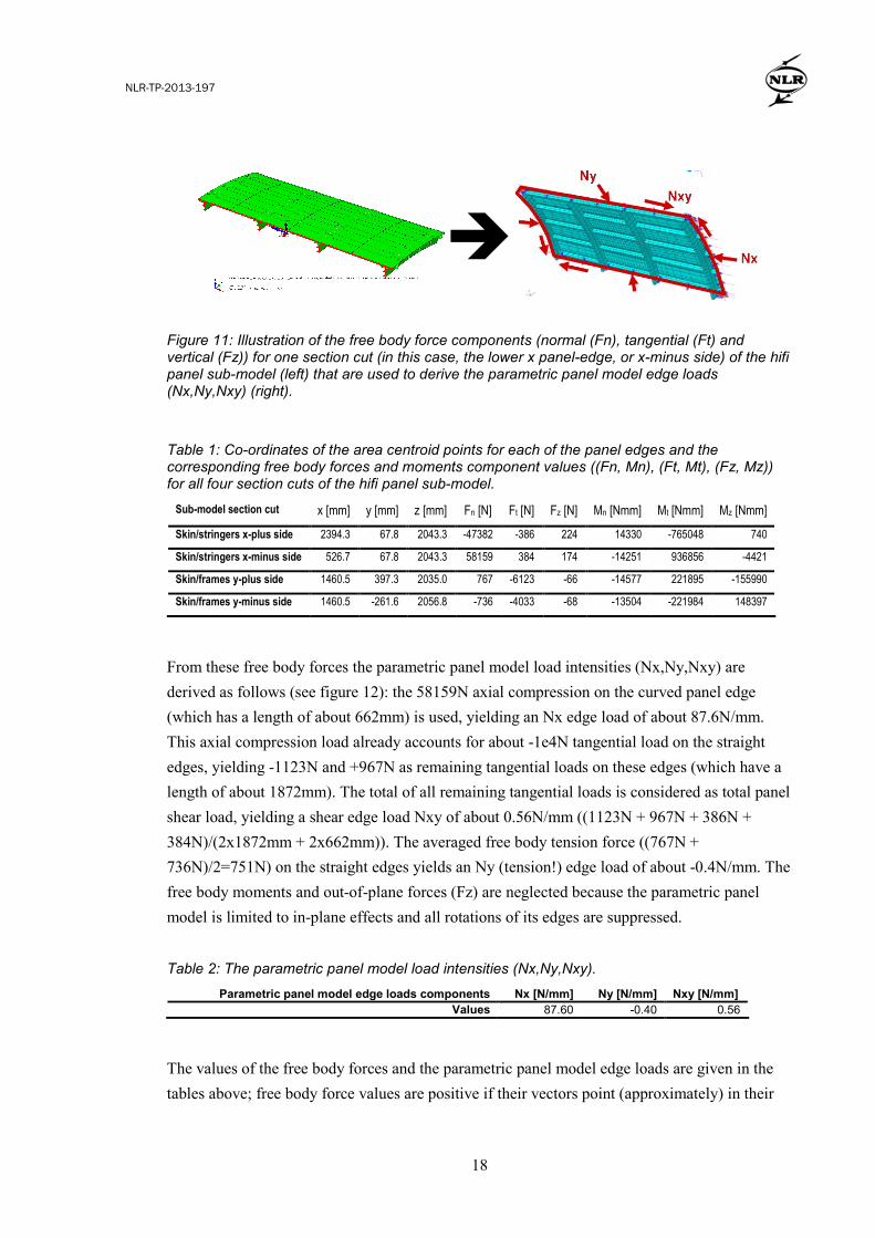
Figure 11: Illustration of the free body force components (normal (Fn), tangential (Ft) and vertical (Fz)) for one section cut (in this case, the lower x panel-edge, or x-minus side) of the hifi panel sub-model (left) that are used to derive the parametric panel model edge loads (Nx,Ny,Nxy) (right).
Table 1: Co-ordinates of the area centroid points for each of the panel edges and the corresponding free body forces and moments component values ((Fn, Mn), (Ft, Mt), (Fz, Mz)) for all four section cuts of the hifi panel sub-model.
Sub-model section cut x [mm] y [mm] z [mm] Fn [N] Ft [N] Fz [N] Mn [Nmm] Mt [Nmm] Mz [Nmm]
Skin/stringers x-plus side 2394.3 67.8 2043.3 -47382 -386 224 14330 -765048 740
Skin/stringers x-minus side 526.7 67.8 2043.3 58159 384 174 -14251 936856 -4421
Skin/frames y-plus side 1460.5 397.3 2035.0 767 -6123 -66 -14577 221895 -155990
Skin/frames y-minus side 1460.5 -261.6 2056.8 -736 -4033 -68 -13504 -221984 148397
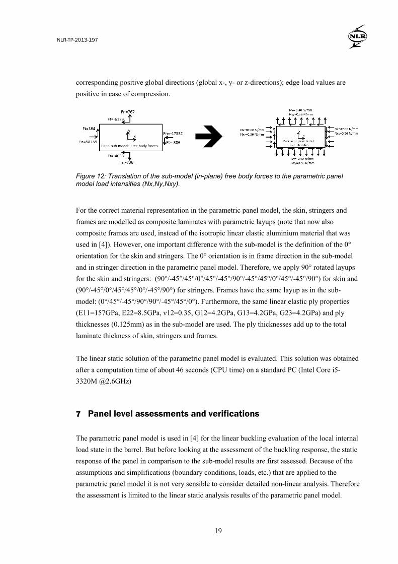
From these free body forces the parametric panel model load intensities (Nx,Ny,Nxy) are derived as follows (see figure 12): the 58159N axial compression on the curved panel edge (which has a length of about 662mm) is used, yielding an Nx edge load of about 87.6N/mm. This axial compression load already accounts for about -1e4N tangential load on the straight edges, yielding -1123N and +967N as remaining tangential loads on these edges (which have a length of about 1872mm). The total of all remaining tangential loads is considered as total panel shear load, yielding a shear edge load Nxy of about 0.56N/mm ((1123N + 967N + 386N + 384N)/(2x1872mm + 2x662mm)). The averaged free body tension force ((767N + 736N)/2=751N) on the straight edges yields an Ny (tension!) edge load of about -0.4N/mm. The free body moments and out-of-plane forces (Fz) are neglected because the parametric panel model is limited to in-plane effects and all rotations of its edges are suppressed. Table 2: The parametric panel model load intensities (Nx,Ny,Nxy).
Parametric panel model edge loads components Nx [N/mm] Ny [N/mm] Nxy [N/mm] Values 87.60 -0.40 0.56
The values of the free body forces and the parametric panel model edge loads are given in the tables above; free body force values are positive if their vectors point (approximately) in their
NLR-TP-2013-197
19
corresponding positive global directions (global x-, y- or z-directions); edge load values are positive in case of compression.
Figure 12: Translation of the sub-model (in-plane) free body forces to the parametric panel model load intensities (Nx,Ny,Nxy).
For the correct material representation in the parametric panel model, the skin, stringers and frames are modelled as composite laminates with parametric layups (note that now also composite frames are used, instead of the isotropic linear elastic aluminium material that was used in [4]). However, one important difference with the sub-model is the definition of the 0° orientation for the skin and stringers. The 0° orientation is in frame direction in the sub-model and in stringer direction in the parametric panel model. Therefore, we apply 90° rotated layups for the skin and stringers: (90°/-45°/45°/0°/45°/-45°/90°/-45°/45°/0°/45°/-45°/90°) for skin and (90°/-45°/0°/45°/45°/0°/-45°/90°) for stringers. Frames have the same layup as in the sub-model: (0°/45°/-45°/90°/90°/-45°/45°/0°). Furthermore, the same linear elastic ply properties (E11=157GPa, E22=8.5GPa, ν12=0.35, G12=4.2GPa, G13=4.2GPa, G23=4.2GPa) and ply thicknesses (0.125mm) as in the sub-model are used. The ply thicknesses add up to the total laminate thickness of skin, stringers and frames. The linear static solution of the parametric panel model is evaluated. This solution was obtained after a computation time of about 46 seconds (CPU time) on a standard PC (Intel Core i5-3320M @2.6GHz) 7 Panel level assessments and verifications
The parametric panel model is used in [4] for the linear buckling evaluation of the local internal load state in the barrel. But before looking at the assessment of the buckling response, the static response of the panel in comparison to the sub-model results are first assessed. Because of the assumptions and simplifications (boundary conditions, loads, etc.) that are applied to the parametric panel model it is not very sensible to consider detailed non-linear analysis. Therefore the assessment is limited to the linear static analysis results of the parametric panel model.
NLR-TP-2013-197
20
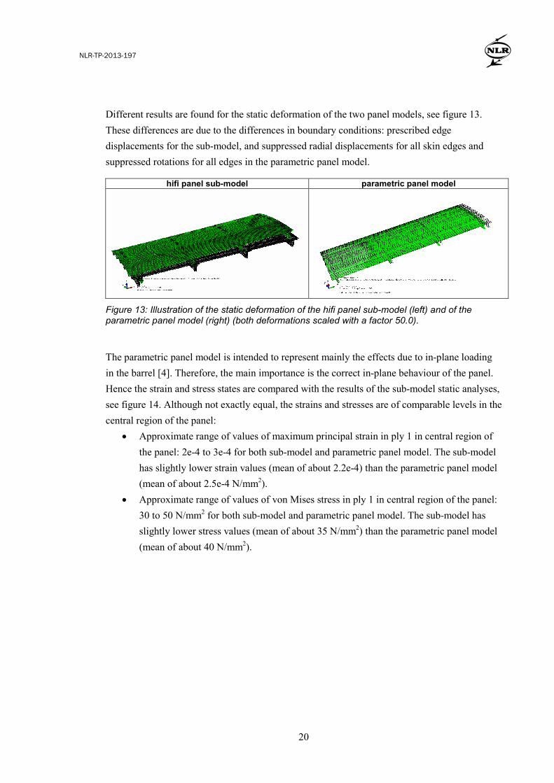
Different results are found for the static deformation of the two panel models, see figure 13. These differences are due to the differences in boundary conditions: prescribed edge displacements for the sub-model, and suppressed radial displacements for all skin edges and suppressed rotations for all edges in the parametric panel model.
hifi panel sub-model parametric panel model
Figure 13: Illustration of the static deformation of the hifi panel sub-model (left) and of the parametric panel model (right) (both deformations scaled with a factor 50.0).
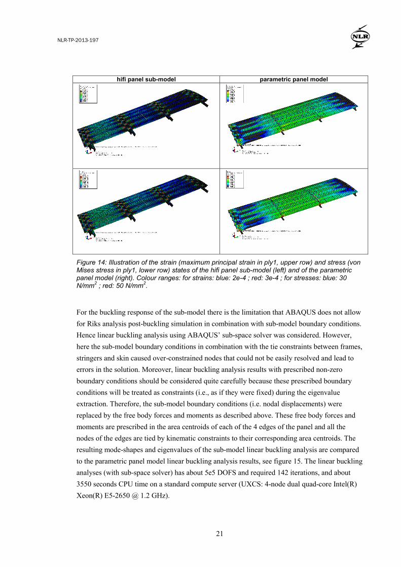
The parametric panel model is intended to represent mainly the effects due to in-plane loading in the barrel [4]. Therefore, the main importance is the correct in-plane behaviour of the panel. Hence the strain and stress states are compared with the results of the sub-model static analyses, see figure 14. Although not exactly equal, the strains and stresses are of comparable levels in the central region of the panel:
• Approximate range of values of maximum principal strain in ply 1 in central region of the panel: 2e-4 to 3e-4 for both sub-model and parametric panel model. The sub-model has slightly lower strain values (mean of about 2.2e-4) than the parametric panel model (mean of about 2.5e-4 N/mm2).
• Approximate range of values of von Mises stress in ply 1 in central region of the panel: 30 to 50 N/mm2 for both sub-model and parametric panel model. The sub-model has slightly lower stress values (mean of about 35 N/mm2) than the parametric panel model (mean of about 40 N/mm2).
NLR-TP-2013-197
21
hifi panel sub-model parametric panel model
Figure 14: Illustration of the strain (maximum principal strain in ply1, upper row) and stress (von Mises stress in ply1, lower row) states of the hifi panel sub-model (left) and of the parametric panel model (right). Colour ranges: for strains: blue: 2e-4 ; red: 3e-4 ; for stresses: blue: 30 N/mm2 ; red: 50 N/mm2.
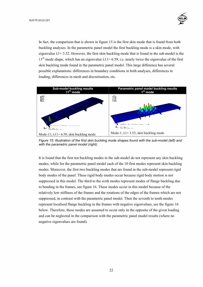
For the buckling response of the sub-model there is the limitation that ABAQUS does not allow for Riks analysis post-buckling simulation in combination with sub-model boundary conditions. Hence linear buckling analysis using ABAQUS’ sub-space solver was considered. However, here the sub-model boundary conditions in combination with the tie constraints between frames, stringers and skin caused over-constrained nodes that could not be easily resolved and lead to errors in the solution. Moreover, linear buckling analysis results with prescribed non-zero boundary conditions should be considered quite carefully because these prescribed boundary conditions will be treated as constraints (i.e., as if they were fixed) during the eigenvalue extraction. Therefore, the sub-model boundary conditions (i.e. nodal displacements) were replaced by the free body forces and moments as described above. These free body forces and moments are prescribed in the area centroids of each of the 4 edges of the panel and all the nodes of the edges are tied by kinematic constraints to their corresponding area centroids. The resulting mode-shapes and eigenvalues of the sub-model linear buckling analysis are compared to the parametric panel model linear buckling analysis results, see figure 15. The linear buckling analyses (with sub-space solver) has about 5e5 DOFS and required 142 iterations, and about 3550 seconds CPU time on a standard compute server (UXCS: 4-node dual quad-core Intel(R) Xeon(R) E5-2650 @ 1.2 GHz).
NLR-TP-2013-197
22
In fact, the comparison that is shown in figure 15 is the first skin mode that is found from both buckling analyses. In the parametric panel model the first buckling mode is a skin mode, with eigenvalue λ1= 3.52. However, the first skin buckling mode that is found in the sub-model is the 11th mode shape, which has an eigenvalue λ11= 6.59, i.e. nearly twice the eigenvalue of the first skin buckling mode found in the parametric panel model. This large difference has several possible explanations: differences in boundary conditions in both analyses, differences in loading, differences in mesh and discretisation, etc.
Sub-model buckling results 11th mode
Parametric panel model buckling results 1st mode
Mode-11; λ11= 6.59; skin buckling mode
Mode-1; λ1= 3.52; skin buckling mode
Figure 15: Illustration of the first skin buckling mode shapes found with the sub-model (left) and with the parametric panel model (right).
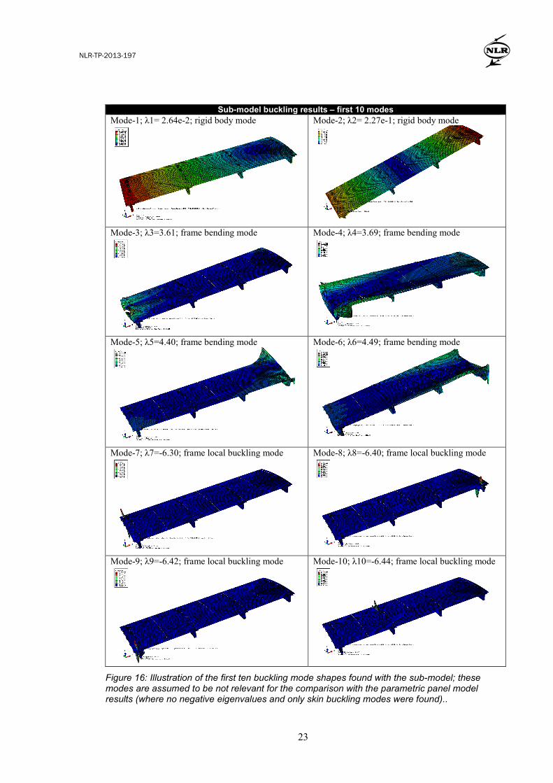
It is found that the first ten buckling modes in the sub-model do not represent any skin buckling modes, while for the parametric panel model each of the 10 first modes represent skin buckling modes. Moreover, the first two buckling modes that are found in the sub-model represent rigid body modes of the panel. These rigid body modes occur because rigid body motion is not suppressed in this model. The third to the sixth modes represent modes of flange buckling due to bending in the frames, see figure 16. These modes occur in this model because of the relatively low stiffness of the frames and the rotations of the edges of the frames which are not suppressed, in contrast with the parametric panel model. Then the seventh to tenth modes represent localised flange buckling in the frames with negative eigenvalues, see the figure 16 below. Therefore, these modes are assumed to occur only in the opposite of the given loading and can be neglected in the comparison with the parametric panel model results (where no negative eigenvalues are found).
NLR-TP-2013-197
23
Sub-model buckling results – first 10 modes Mode-1; λ1= 2.64e-2; rigid body mode
Mode-2; λ2= 2.27e-1; rigid body mode
Mode-3; λ3=3.61; frame bending mode
Mode-4; λ4=3.69; frame bending mode
Mode-5; λ5=4.40; frame bending mode
Mode-6; λ6=4.49; frame bending mode
Mode-7; λ7=-6.30; frame local buckling mode
Mode-8; λ8=-6.40; frame local buckling mode
Mode-9; λ9=-6.42; frame local buckling mode
Mode-10; λ10=-6.44; frame local buckling mode
Figure 16: Illustration of the first ten buckling mode shapes found with the sub-model; these modes are assumed to be not relevant for the comparison with the parametric panel model results (where no negative eigenvalues and only skin buckling modes were found)..
NLR-TP-2013-197
24
8 Conclusions and discussion
This paper presents a verification assessment of buckling analyses on relatively simple parametric FE models of stiffened composite panels that are used in a multi-level optimisation methodology of composite fuselage structures. In the optimisation methodology, the panel loads are obtained from FE analyses on fuselage barrel level. On the panel level, the loads and boundary conditions are limited to the in-plane behaviour of the fuselage barrel, which allows for efficient parametric panel level analyses and optimisations. The parametric panel model has a relatively small size (about 42e3 DOFS) and the FE buckling analyses can be quickly evaluated (about 45 second CPU time on a standard PC). Moreover, the simplified (in-plane) load representation by 3 components in the parametric panel model allows for reasonably accurate surrogate model representation of the panel buckling load with a limited number of FE buckling analyses (Design Of Experiment (DOE) size of the order of 1e4 [4], for both the load and sizing parameters). This surrogate model is exploited in the panel level optimisation, where no more FE buckling analyses are required. In this study we consider a hifi FE model of a 20-frame fuselage barrel, which is based on a generic single aisle aircraft fuselage. A hifi panel model is obtained by sub-model extraction from the hifi barrel FE model. Static stress and linear buckling analyses are executed with these hifi FE models. To significantly improve the accuracy of the barrel level and panel level analyses, the hifi barrel model and panel sub-model could be used instead of the barrel GFEM and the parametric panel model. However, model complexity and computational cost would also increase significantly (25e6 and 5e5 DOFS, instead of the 24e3 and 40e3 DOFS in the barrel GFEM and the parametric panel model). Furthermore, the panel sub-model analysis, with appropriate boundary conditions (i.e. prescribed displacements), should be re-defined for each location on the barrel and for each load case. Moreover, the modelling effort would increase significantly, among others because the hifi panel sub-model geometry shall be extracted from the local barrel geometry, which varies over different locations in the barrel (e.g. due to varying curvature radius and stringers pitch and shape over the circumference of the hifi barrel model). Therefore the efficient automation of the sub-modelling procedure and integration into the multi-level optimisation methodology is quite complex and requires ample further development. The accuracy of the panel level buckling analysis as executed in the optimisation methodology with the parametric panel model is quite limited when compared to the buckling results as
NLR-TP-2013-197
25
obtained with the hifi panel sub-model. The stress and strain distribution as obtained from static
analyses showed reasonable correspondence between the coarse parametric panel model and the
hifi panel sub-model. The different results are mainly due to the differences in boundary
conditions and loading between the models. Obviously the buckling response is much more
sensitive to these differences, e.g. the rotations of the edges of skin, stringers and frames that are
fixed in the parametric model whereas in the panel sub-model kinematic constraints are applied
to these edges. The precise background for these discrepancies should
be further investigated, also because the present study was limited to only one load case.
In conclusion, the current approach in the optimisation methodology based on the low fidelity
barrel and panel models, is considered as practically most feasible and still reasonably accurate,
especially for static stress simulation.
References
[1] C. Kasapoglou, Design and analysis of composite structures: with applications to aerospace
structures, Wiley, 2010.
[2] S. Grihon, L. Krog and D. Bassir, Numerical Optimization applied to structure sizing at AIRBUS:
A multi-step process, Int. J. Simul. Mult. Des. Optim. 3, 432-442, 2009.
[3] P. Kaletta, K. Wolf and D. Hachenberg, Optimisation of composite aircraft panels using efficiency
enhancing evolutionary algorithms, ICAS2006, Hamburg, Germany, 2006.
[4] W.J. Vankan, R. Maas and S. Grihon, Efficient optimisation of large aircraft fuselage structures,
RAeS 3rd Aircraft Structural Design Conference, Delft, the Netherlands, 2012. (NLR-TP-2012-
377).
[5] W.J. Vankan, W.F. Lammen and R. Maas, Meta-modeling and multi-objective optimization in
aircraft design, in: Advances in Collaborative Civil Aeronautical Multidisciplinary Design
Optimization, chapter 6, E. Kesseler, M. Guenov, eds., AIAA, 2010. (NLR-TP-2009-718).
[6] The Mathworks, http://www.mathworks.nl/products/matlab/ (accessed 13-2-2013).
[7] MSC Software, MSC NASTRAN http://www.mscsoftware.com/products/cae-tools/msc-
nastran.aspx (accessed 13-2-2013).
[8] Dassault Systèmes Simulia, http://www.3ds.com/products/simulia/portfolio/abaqus/overview/
(accessed 13-2-2013).
Acknowledgements
The research leading to these results has received funding from the European Community’s
Seventh Framework Programme FP7/2007-2013 under grant agreement n°213371
(MAAXIMUS, www.maaximus.eu).