Embed Size (px)
Citation preview
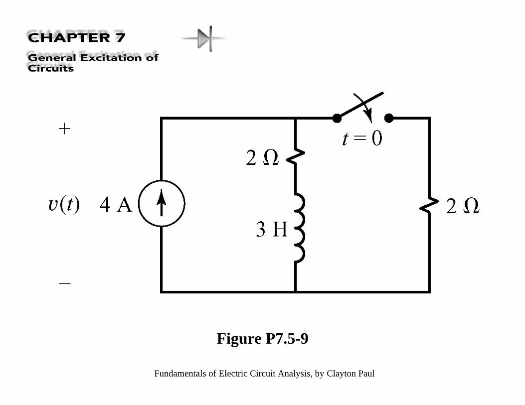
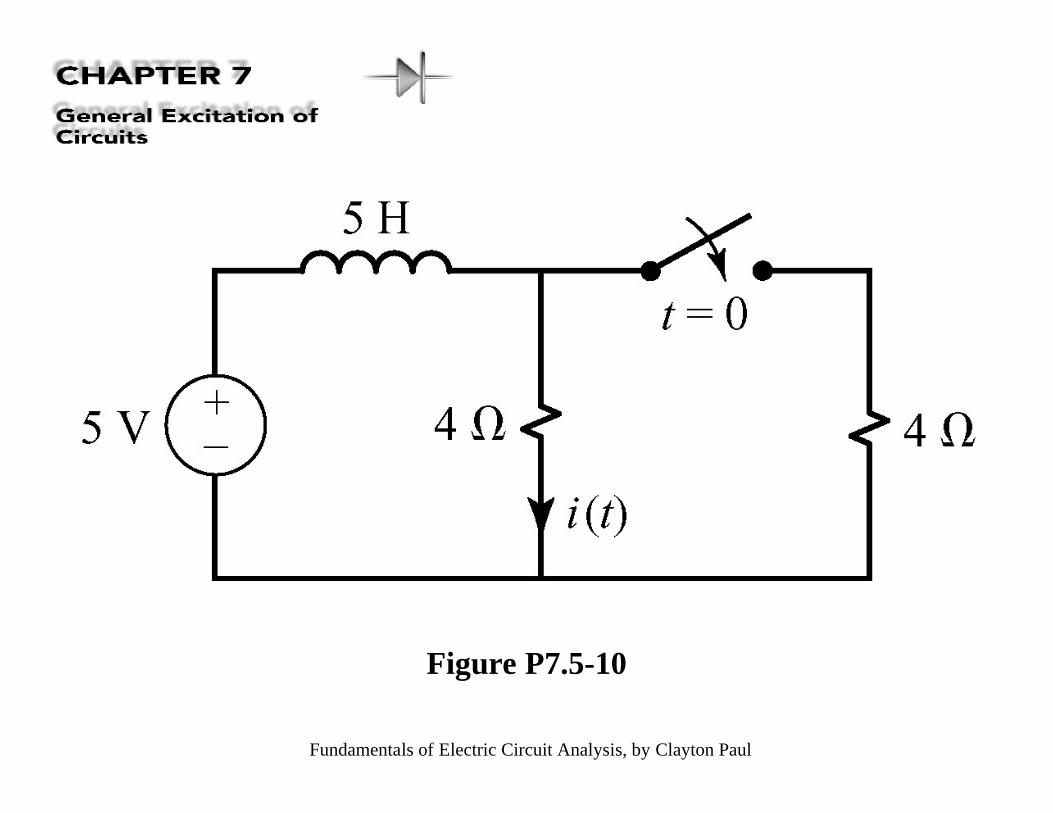
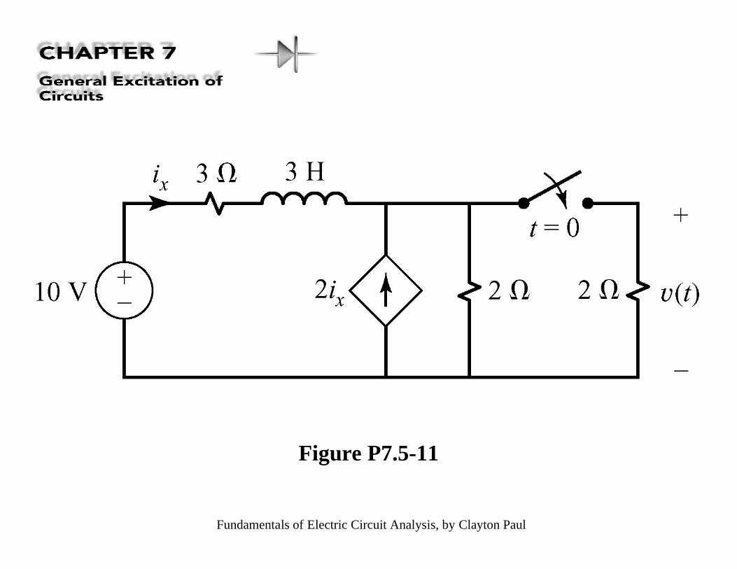
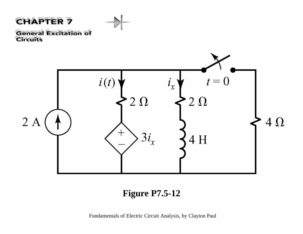
Fundamentals of Electric Circuit Analysis, by Clayton Paul
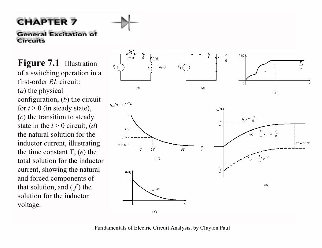
Figure 7.1 Illustrationof a switching operation in afirst-order RL circuit:(a) the physicalconfiguration, (b) the circuitfor t > 0 (in steady state),(c) the transition to steadystate in the t > 0 circuit, (d)the natural solution for theinductor current, illustratingthe time constant T, (e) thetotal solution for the inductorcurrent, showing the naturaland forced components ofthat solution, and ( f ) thesolution for the inductorvoltage.
Fundamentals of Electric Circuit Analysis, by Clayton Paul
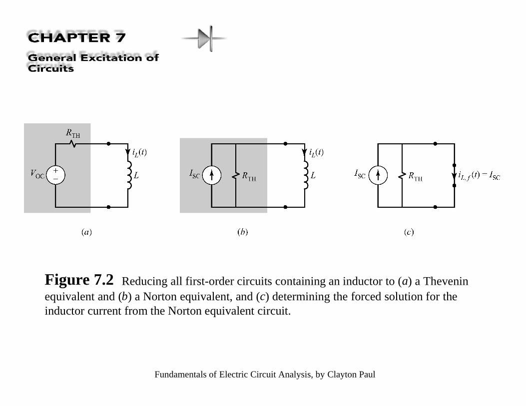
Figure 7.2 Reducing all first-order circuits containing an inductor to (a) a Theveninequivalent and (b) a Norton equivalent, and (c) determining the forced solution for theinductor current from the Norton equivalent circuit.
Fundamentals of Electric Circuit Analysis, by Clayton Paul
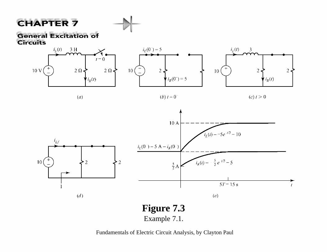
Figure 7.3Example 7.1.
Fundamentals of Electric Circuit Analysis, by Clayton Paul
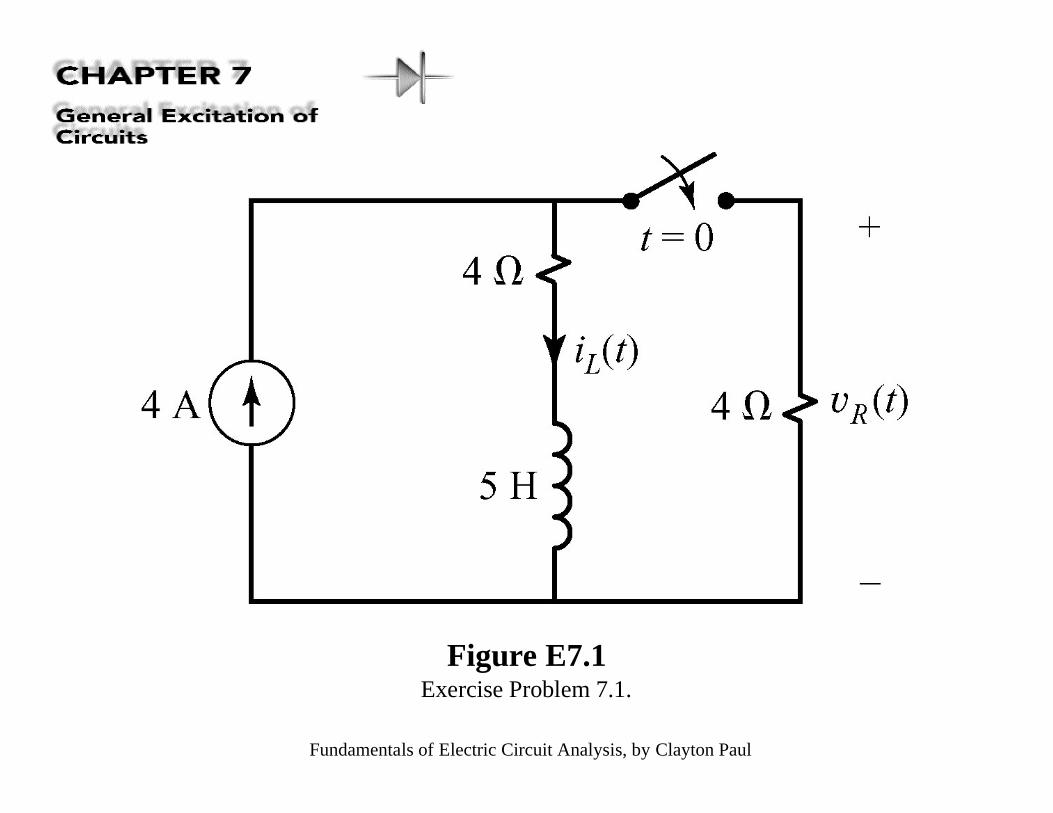
Figure E7.1Exercise Problem 7.1.
Fundamentals of Electric Circuit Analysis, by Clayton Paul
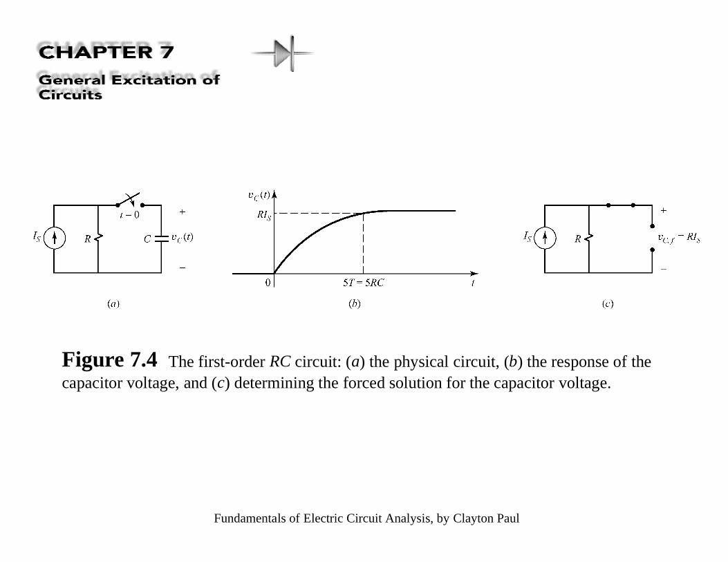
Figure 7.4 The first-order RC circuit: (a) the physical circuit, (b) the response of thecapacitor voltage, and (c) determining the forced solution for the capacitor voltage.
Fundamentals of Electric Circuit Analysis, by Clayton Paul
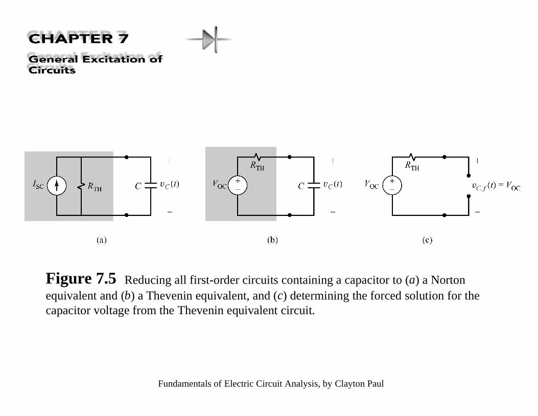
Figure 7.5 Reducing all first-order circuits containing a capacitor to (a) a Nortonequivalent and (b) a Thevenin equivalent, and (c) determining the forced solution for thecapacitor voltage from the Thevenin equivalent circuit.
Fundamentals of Electric Circuit Analysis, by Clayton Paul
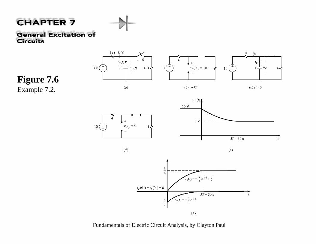
Figure 7.6Example 7.2.
Fundamentals of Electric Circuit Analysis, by Clayton Paul
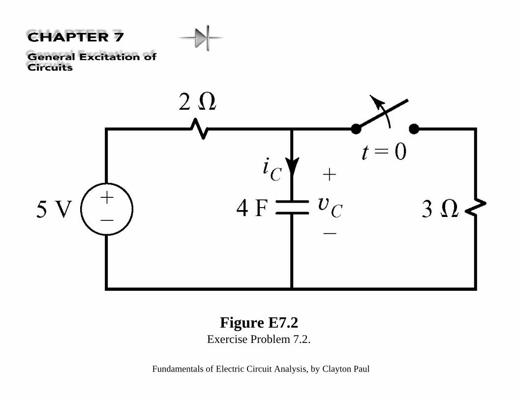
Figure E7.2Exercise Problem 7.2.
Fundamentals of Electric Circuit Analysis, by Clayton Paul
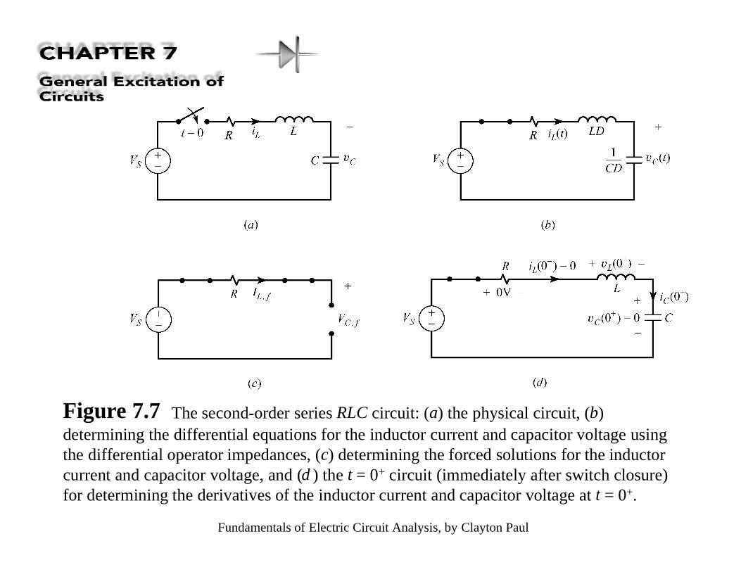
Figure 7.7 The second-order series RLC circuit: (a) the physical circuit, (b)determining the differential equations for the inductor current and capacitor voltage usingthe differential operator impedances, (c) determining the forced solutions for the inductorcurrent and capacitor voltage, and (d ) the t = 0+ circuit (immediately after switch closure)for determining the derivatives of the inductor current and capacitor voltage at t = 0+.
Fundamentals of Electric Circuit Analysis, by Clayton Paul
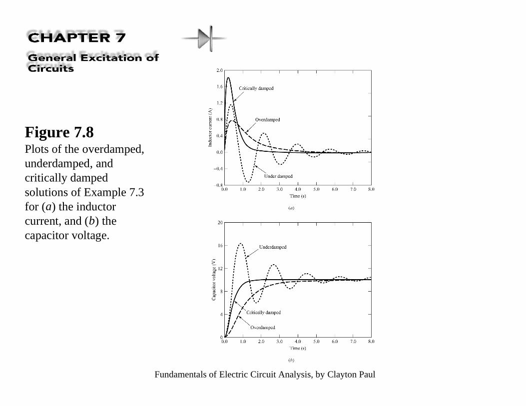
Figure 7.8Plots of the overdamped,underdamped, andcritically dampedsolutions of Example 7.3for (a) the inductorcurrent, and (b) thecapacitor voltage.
Fundamentals of Electric Circuit Analysis, by Clayton Paul
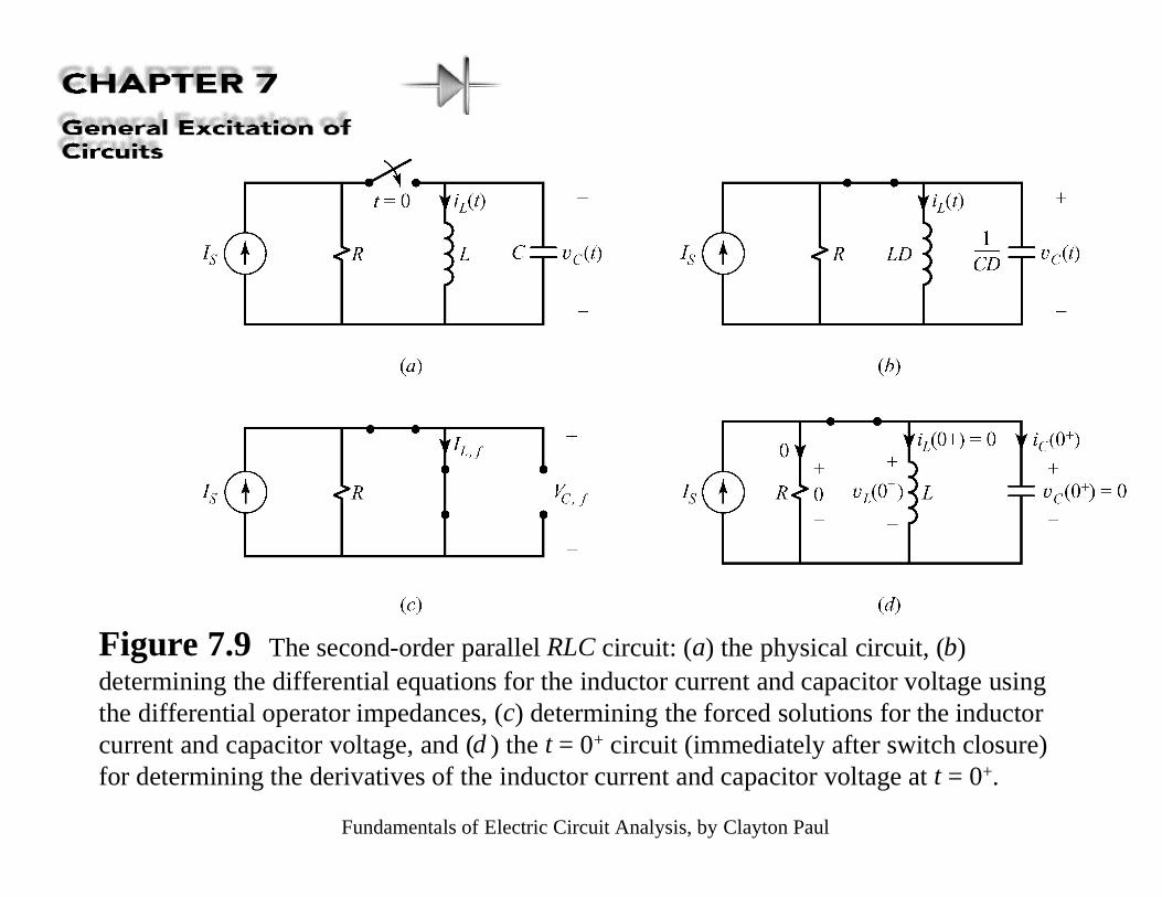
Figure 7.9 The second-order parallel RLC circuit: (a) the physical circuit, (b)determining the differential equations for the inductor current and capacitor voltage usingthe differential operator impedances, (c) determining the forced solutions for the inductorcurrent and capacitor voltage, and (d ) the t = 0+ circuit (immediately after switch closure)for determining the derivatives of the inductor current and capacitor voltage at t = 0+.
Fundamentals of Electric Circuit Analysis, by Clayton Paul
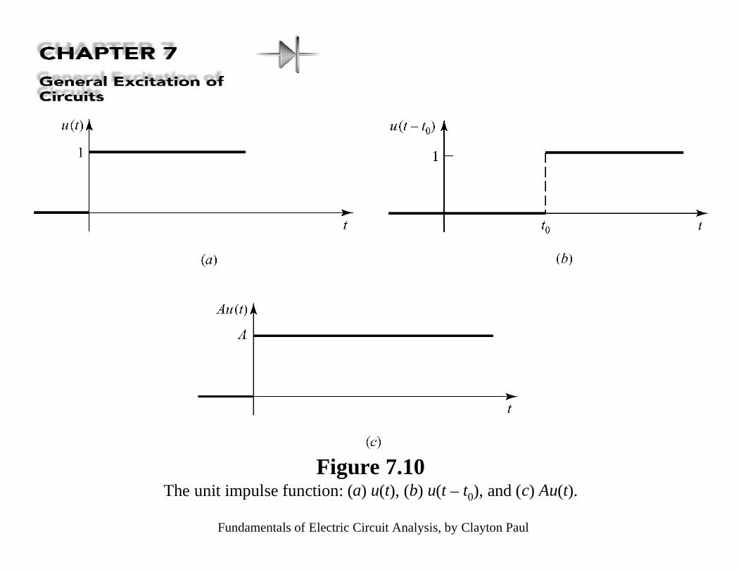
Figure 7.10The unit impulse function: (a) u(t), (b) u(t – t0), and (c) Au(t).
Fundamentals of Electric Circuit Analysis, by Clayton Paul
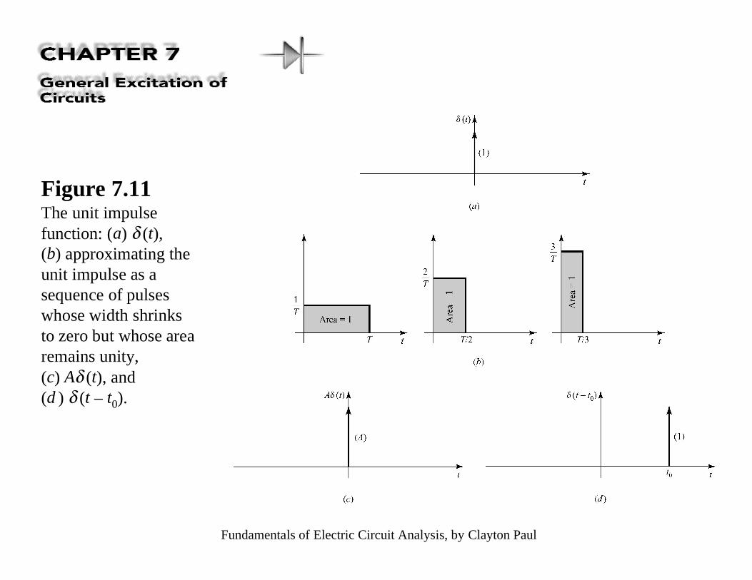
Figure 7.11The unit impulsefunction: (a) δ (t),(b) approximating theunit impulse as asequence of pulseswhose width shrinksto zero but whose arearemains unity,(c) Aδ (t), and(d ) δ (t – t0).
Fundamentals of Electric Circuit Analysis, by Clayton Paul
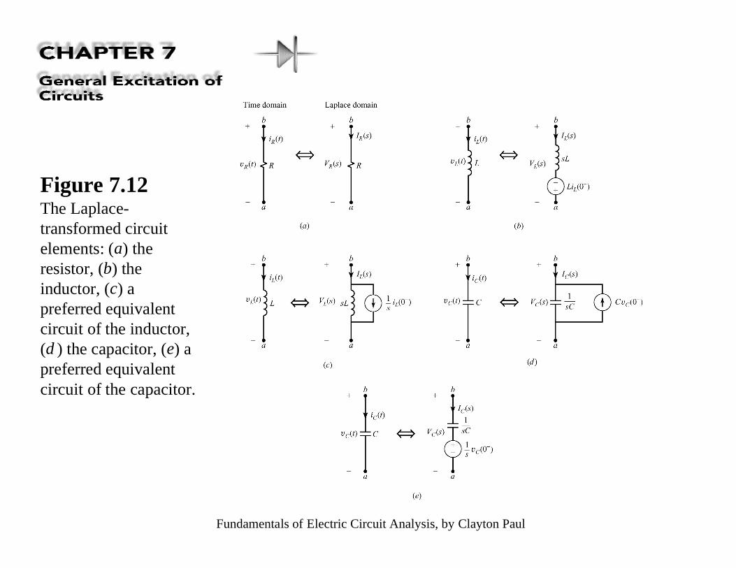
Figure 7.12The Laplace-transformed circuitelements: (a) theresistor, (b) theinductor, (c) apreferred equivalentcircuit of the inductor,(d ) the capacitor, (e) apreferred equivalentcircuit of the capacitor.
Fundamentals of Electric Circuit Analysis, by Clayton Paul
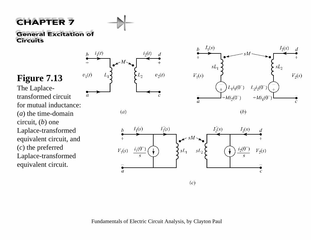
Figure 7.13The Laplace-transformed circuitfor mutual inductance:(a) the time-domaincircuit, (b) oneLaplace-transformedequivalent circuit, and(c) the preferredLaplace-transformedequivalent circuit.
Fundamentals of Electric Circuit Analysis, by Clayton Paul
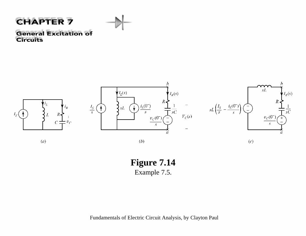
Figure 7.14Example 7.5.
Fundamentals of Electric Circuit Analysis, by Clayton Paul
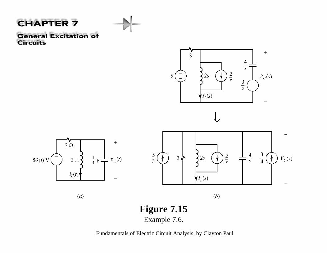
Figure 7.15Example 7.6.
Fundamentals of Electric Circuit Analysis, by Clayton Paul
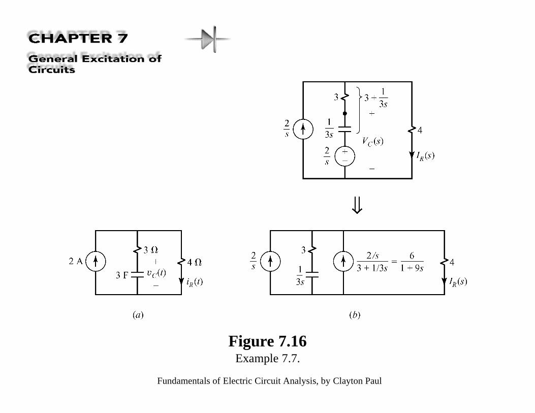
Figure 7.16Example 7.7.
Fundamentals of Electric Circuit Analysis, by Clayton Paul
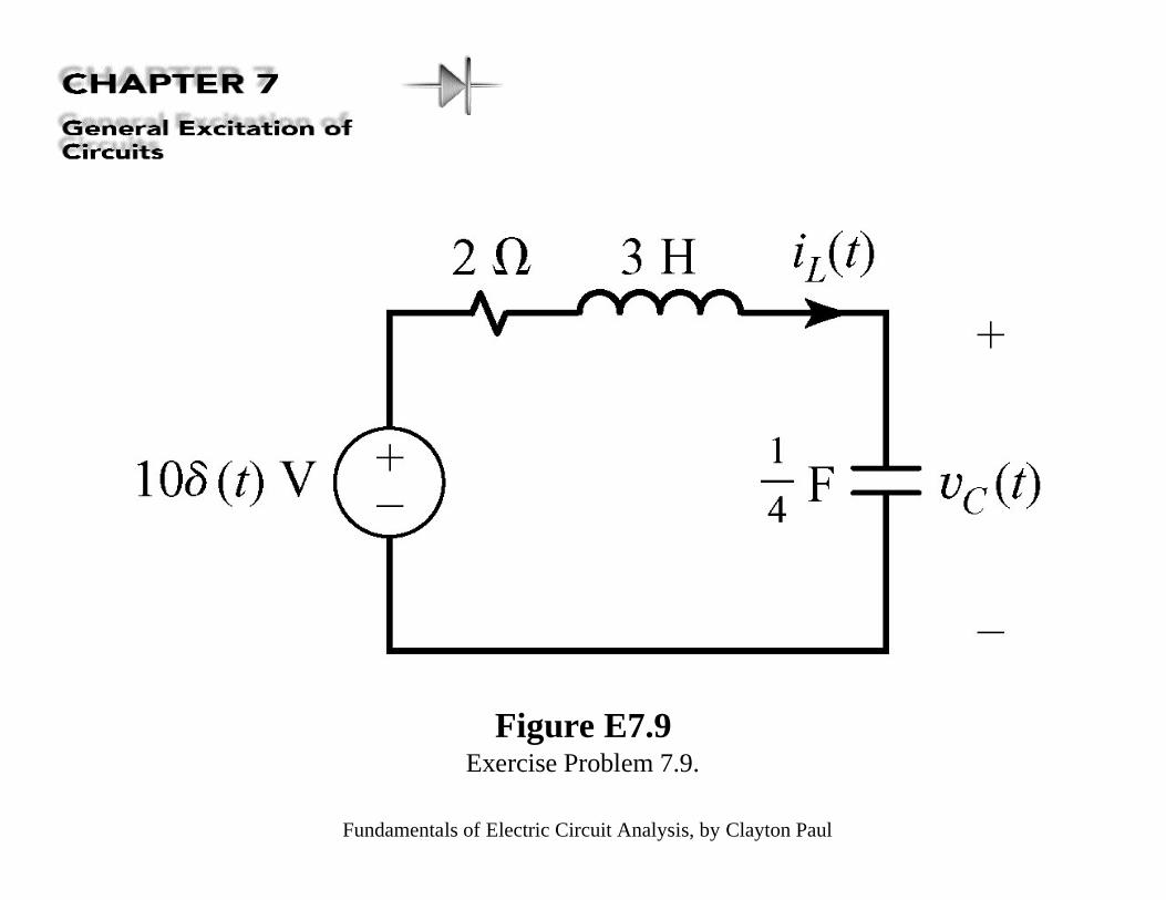
Figure E7.9Exercise Problem 7.9.
Fundamentals of Electric Circuit Analysis, by Clayton Paul
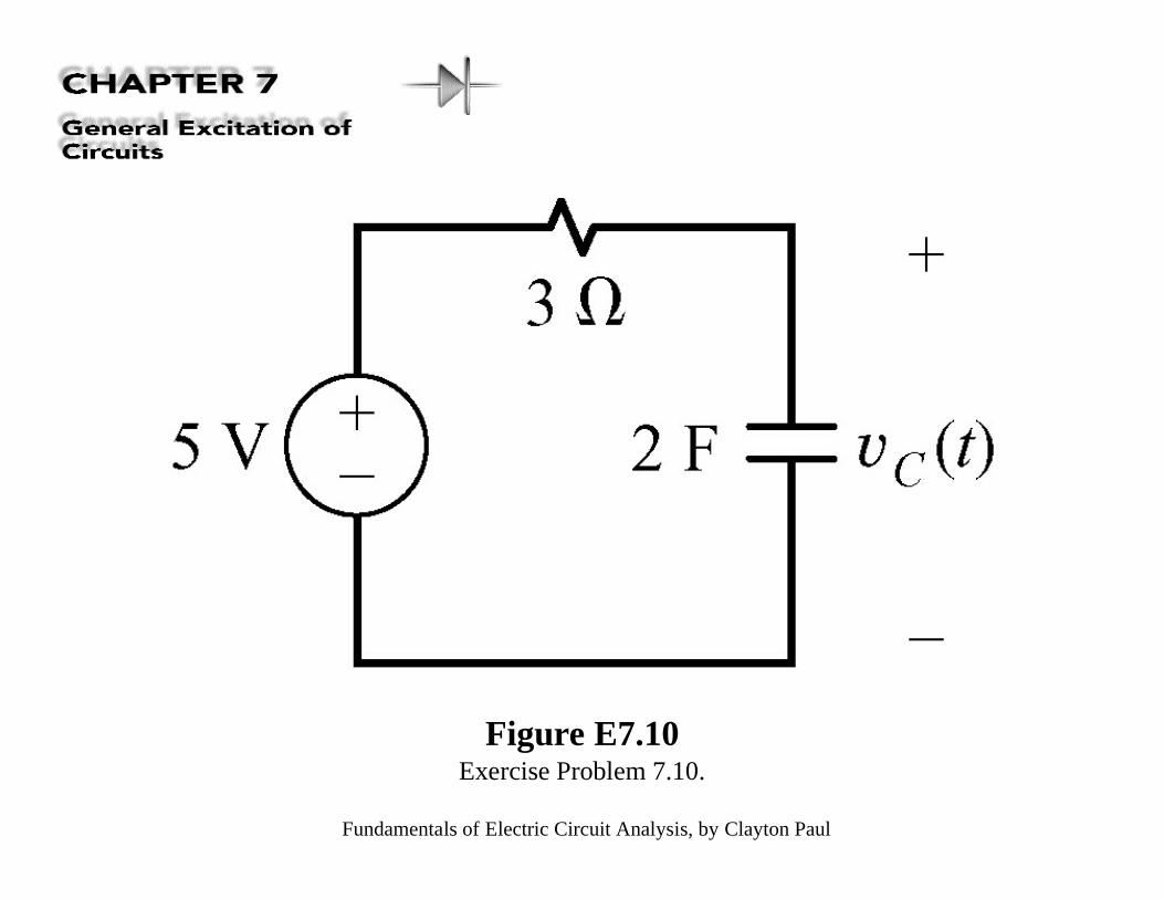
Figure E7.10Exercise Problem 7.10.
Fundamentals of Electric Circuit Analysis, by Clayton Paul
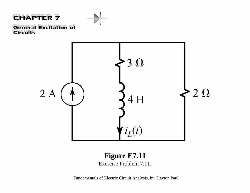
Figure E7.11Exercise Problem 7.11.
Fundamentals of Electric Circuit Analysis, by Clayton Paul
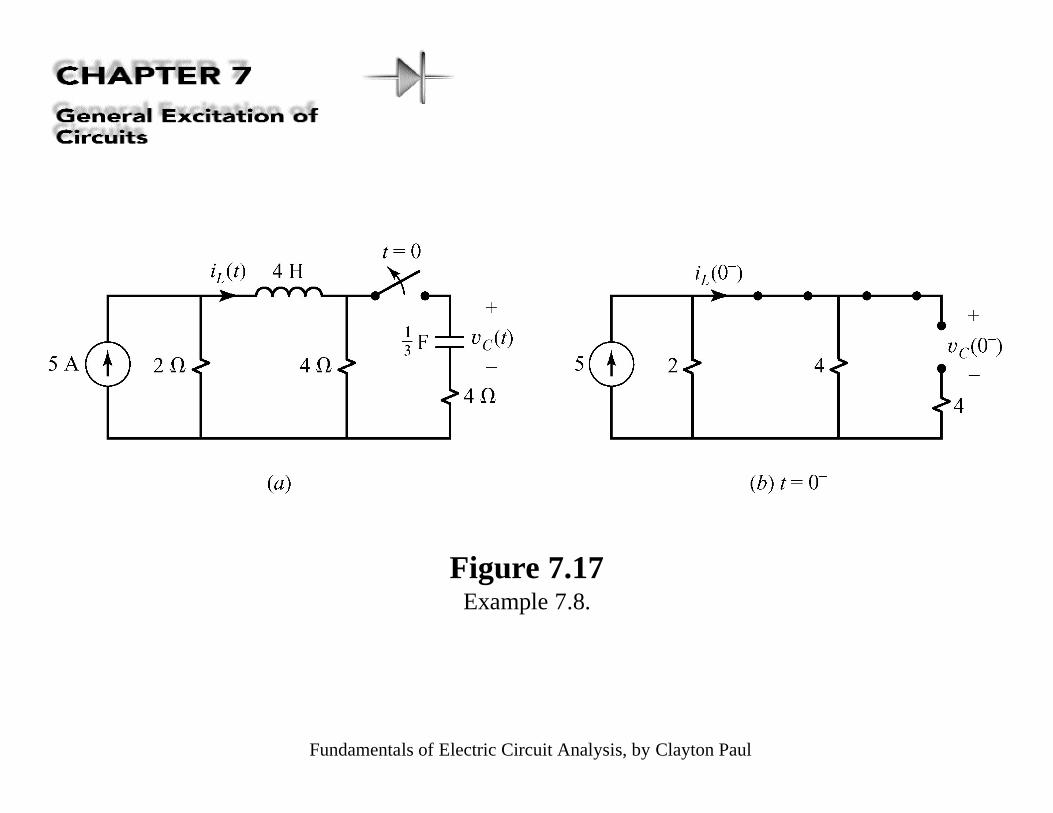
Figure 7.17Example 7.8.
Fundamentals of Electric Circuit Analysis, by Clayton Paul
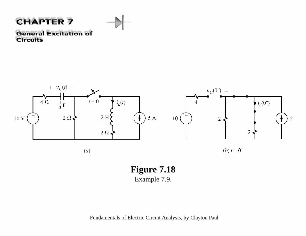
Figure 7.18Example 7.9.
Fundamentals of Electric Circuit Analysis, by Clayton Paul
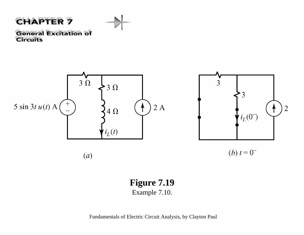
Figure 7.19Example 7.10.
Fundamentals of Electric Circuit Analysis, by Clayton Paul
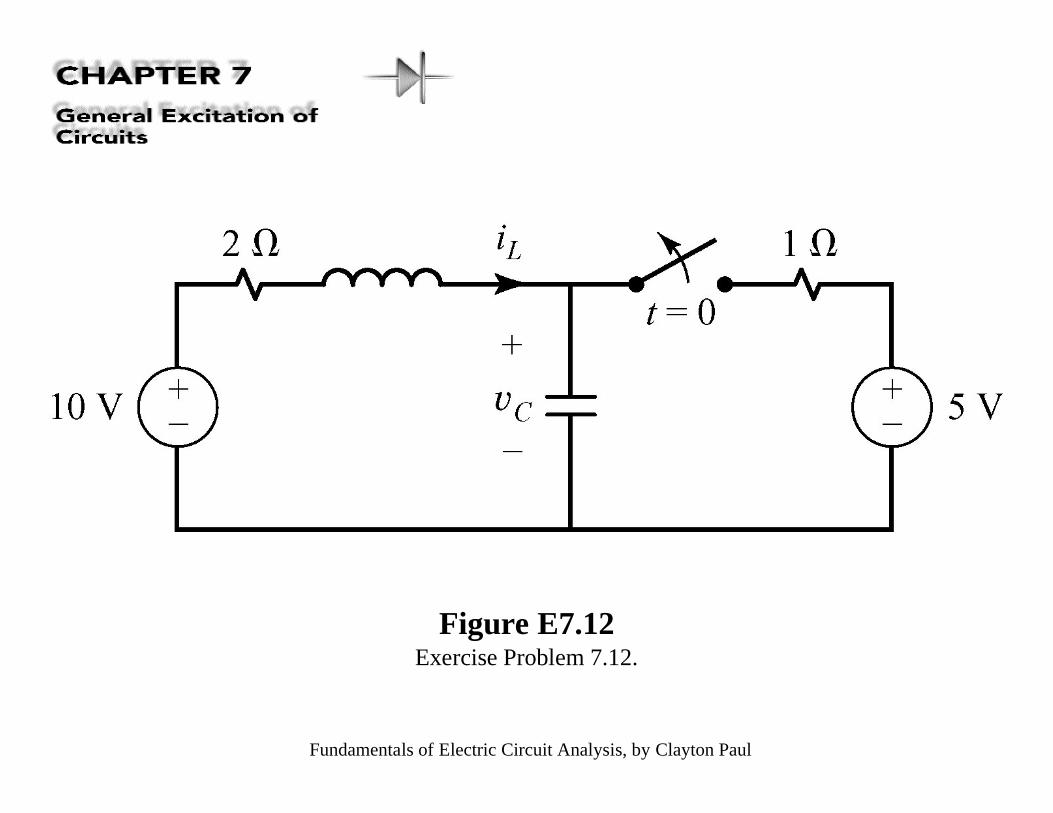
Figure E7.12Exercise Problem 7.12.
Fundamentals of Electric Circuit Analysis, by Clayton Paul
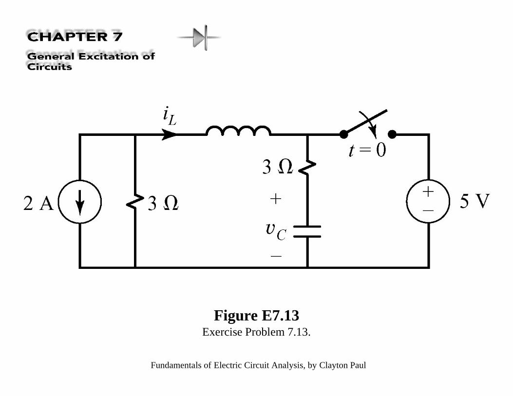
Figure E7.13Exercise Problem 7.13.
Fundamentals of Electric Circuit Analysis, by Clayton Paul
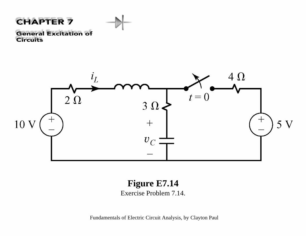
Figure E7.14Exercise Problem 7.14.
Fundamentals of Electric Circuit Analysis, by Clayton Paul
Figure 7.20Solution of the first-order RLcircuit with the Laplacetransform method: (a) thetime-domain circuit, (b) theLaplace transformed circuit,(c) using superposition todetermine the portion of theresponse due to the inductorinitial current and the portionof the response due to theopen-circuit voltage source(which represents the effect ofthe actual sources in thecircuit), (d ) plot of theinductor current response, and(e) plot of the inductor voltageresponse.
Fundamentals of Electric Circuit Analysis, by Clayton Paul
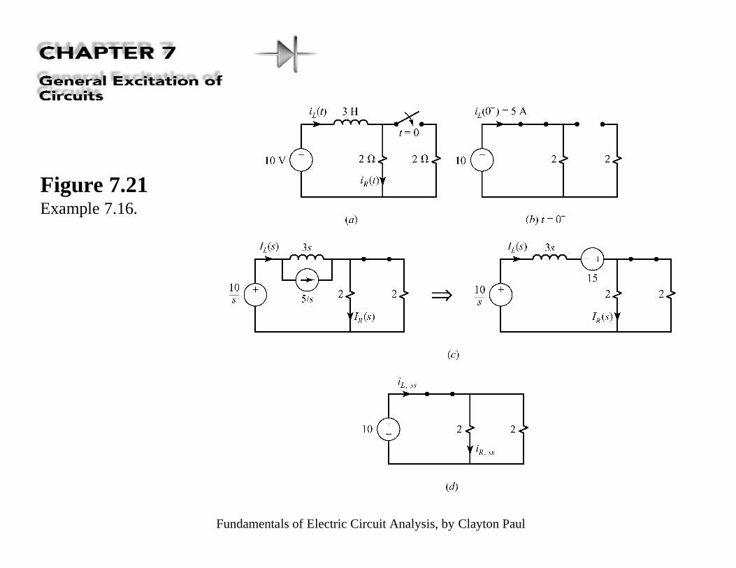
Figure 7.21Example 7.16.
Fundamentals of Electric Circuit Analysis, by Clayton Paul
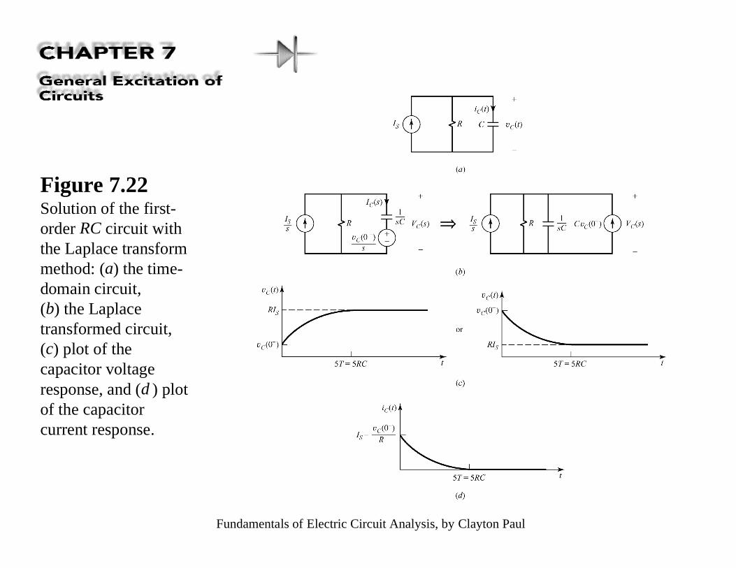
Figure 7.22Solution of the first-order RC circuit withthe Laplace transformmethod: (a) the time-domain circuit,(b) the Laplacetransformed circuit,(c) plot of thecapacitor voltageresponse, and (d ) plotof the capacitorcurrent response.
Fundamentals of Electric Circuit Analysis, by Clayton Paul
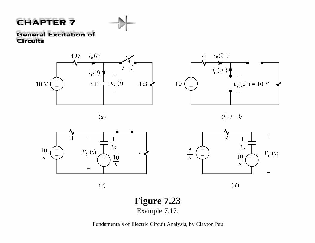
Figure 7.23Example 7.17.
Fundamentals of Electric Circuit Analysis, by Clayton Paul
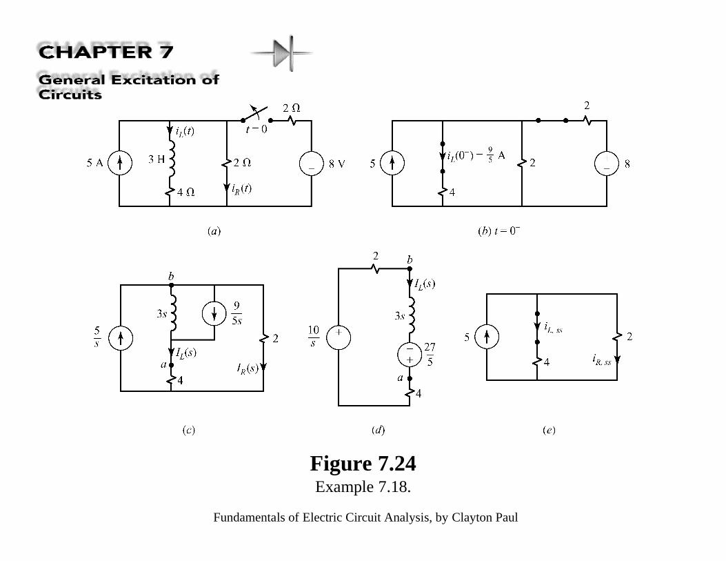
Figure 7.24Example 7.18.
Fundamentals of Electric Circuit Analysis, by Clayton Paul
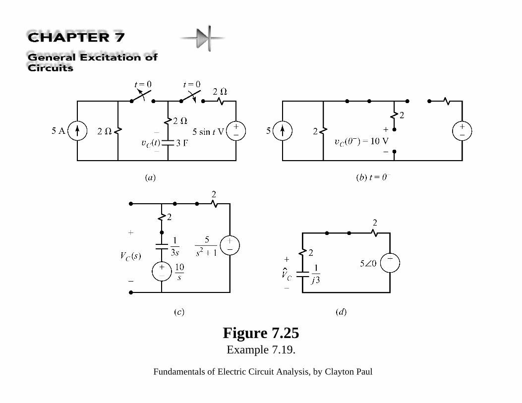
Figure 7.25Example 7.19.
Fundamentals of Electric Circuit Analysis, by Clayton Paul
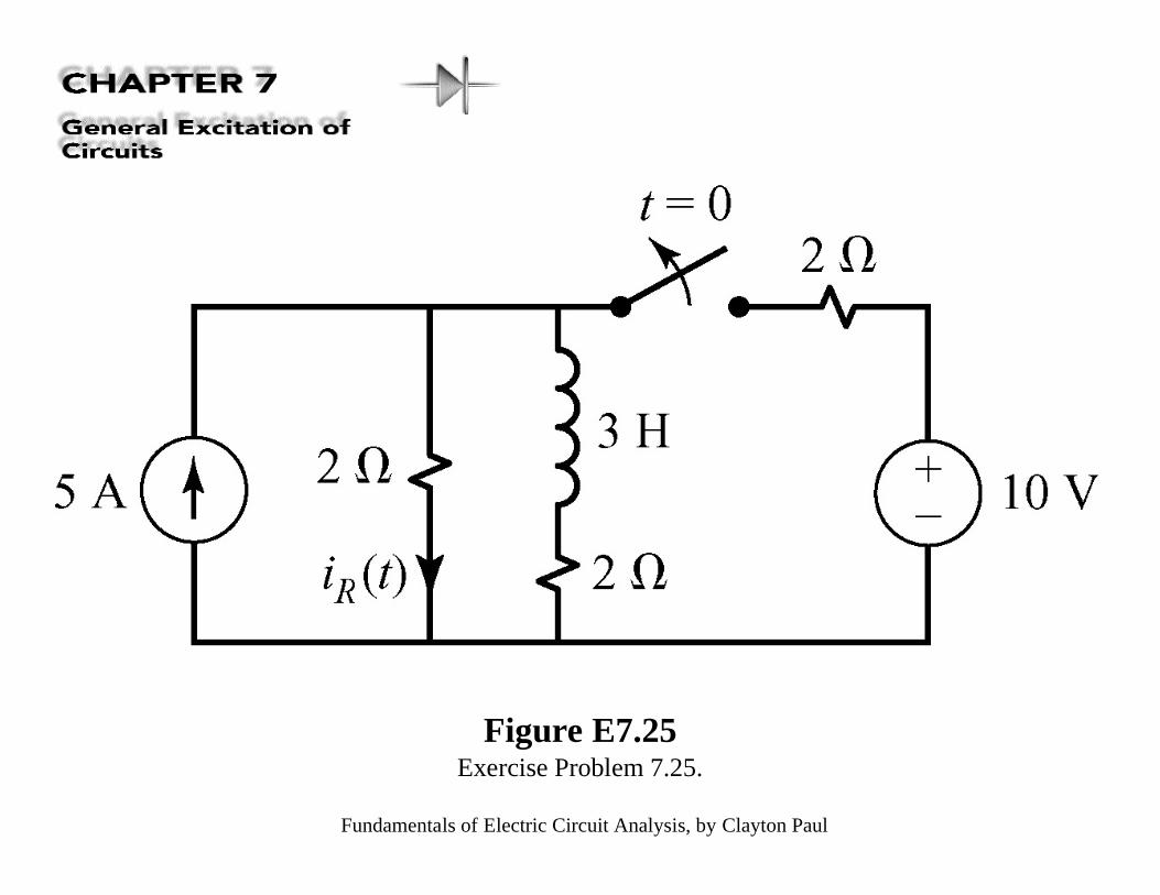
Figure E7.25Exercise Problem 7.25.
Fundamentals of Electric Circuit Analysis, by Clayton Paul
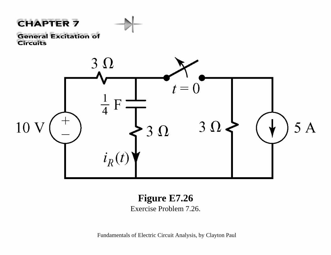
Figure E7.26Exercise Problem 7.26.
Fundamentals of Electric Circuit Analysis, by Clayton Paul
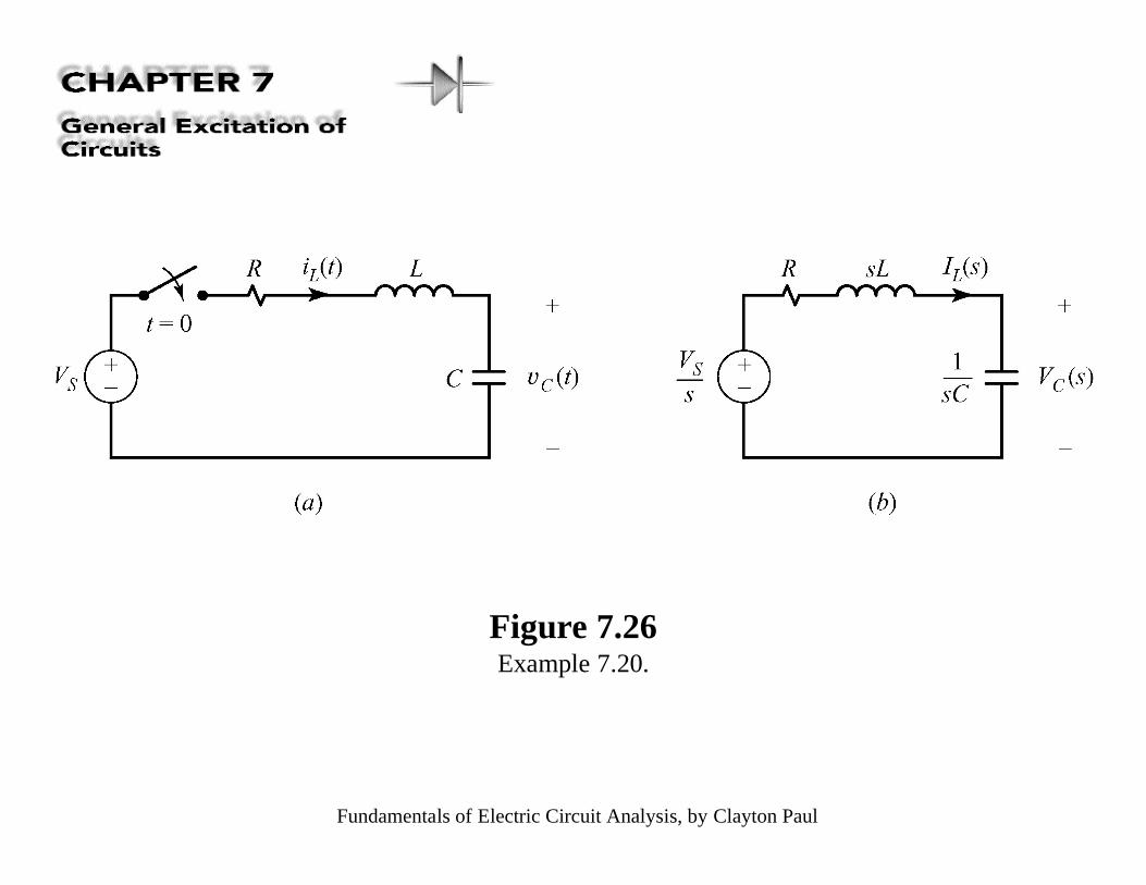
Figure 7.26Example 7.20.
Fundamentals of Electric Circuit Analysis, by Clayton Paul
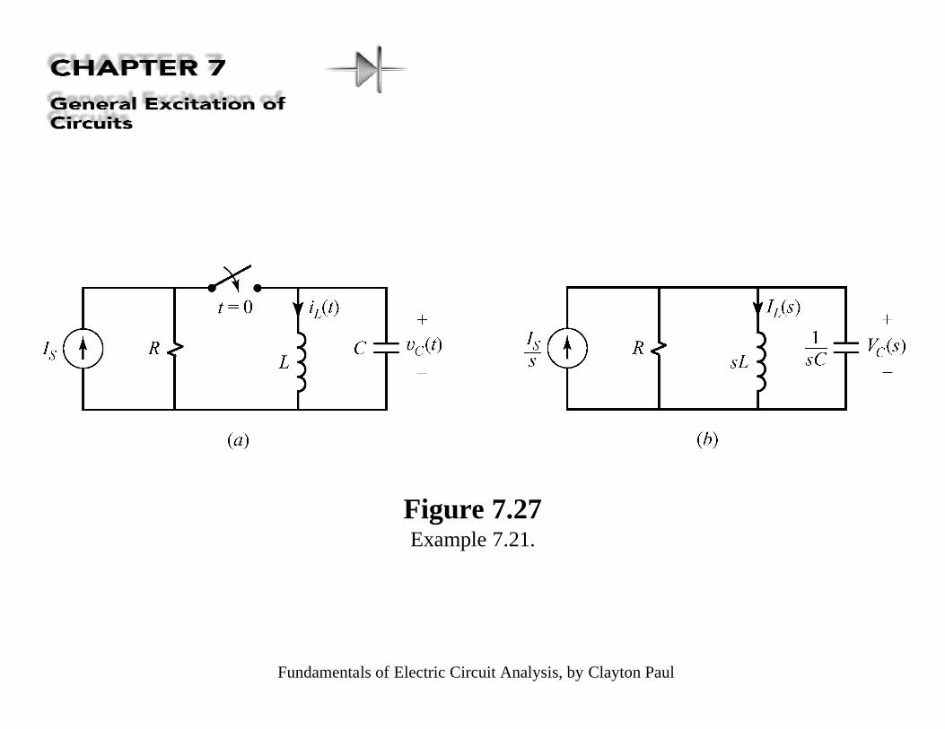
Figure 7.27Example 7.21.
Fundamentals of Electric Circuit Analysis, by Clayton Paul
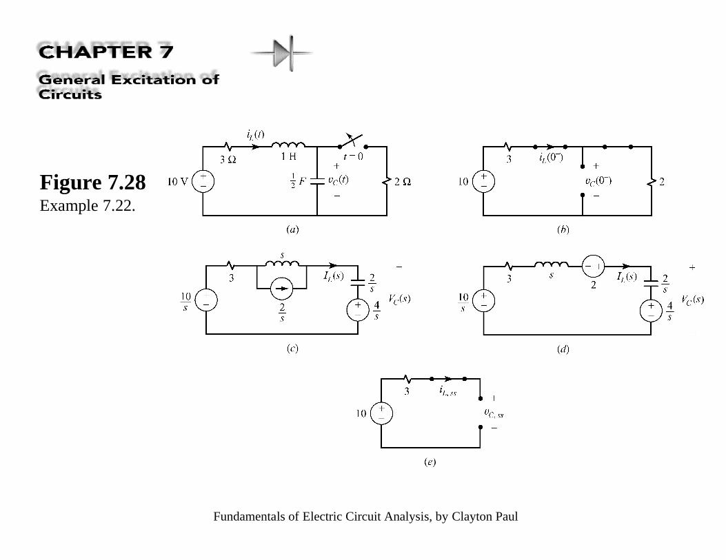
Figure 7.28Example 7.22.

Fundamentals of Electric Circuit Analysis, by Clayton Paul
Figure 7.29Example 7.23.
Fundamentals of Electric Circuit Analysis, by Clayton Paul
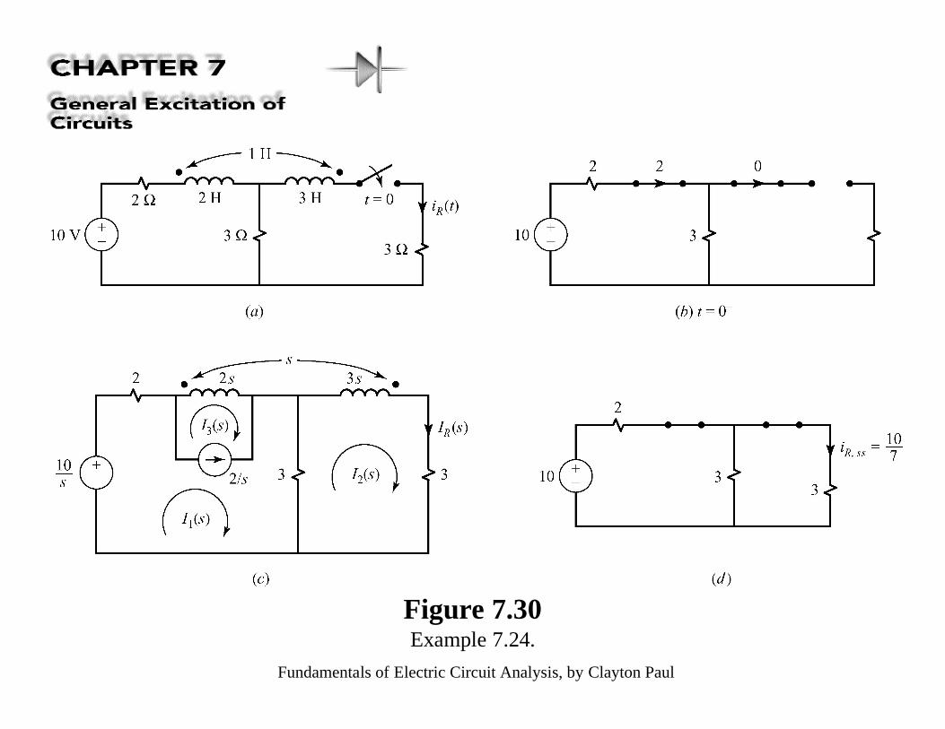
Figure 7.30Example 7.24.
Fundamentals of Electric Circuit Analysis, by Clayton Paul
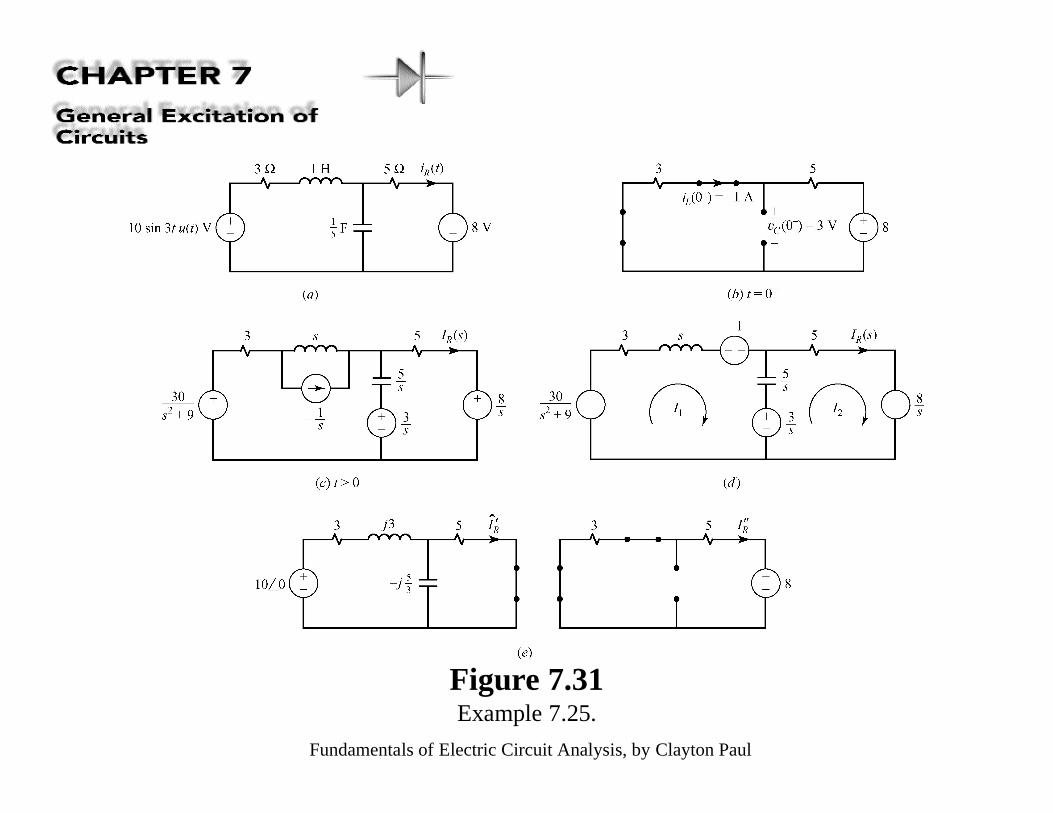
Figure 7.31Example 7.25.
Fundamentals of Electric Circuit Analysis, by Clayton Paul
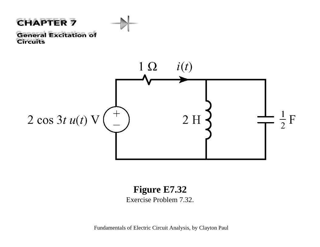
Figure E7.32Exercise Problem 7.32.
Fundamentals of Electric Circuit Analysis, by Clayton Paul
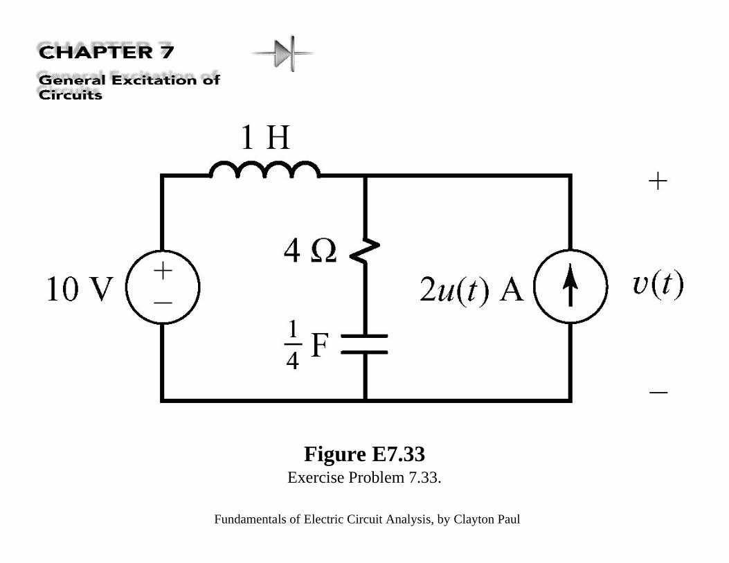
Figure E7.33Exercise Problem 7.33.
Fundamentals of Electric Circuit Analysis, by Clayton Paul
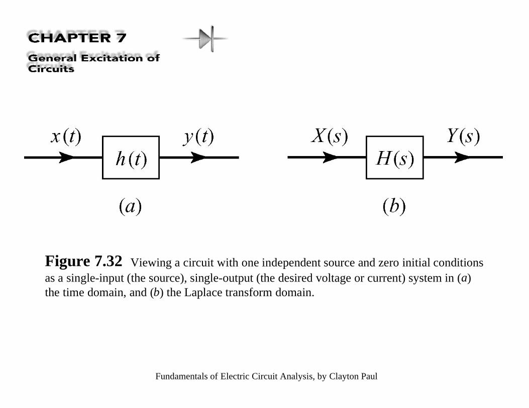
Figure 7.32 Viewing a circuit with one independent source and zero initial conditionsas a single-input (the source), single-output (the desired voltage or current) system in (a)the time domain, and (b) the Laplace transform domain.
Fundamentals of Electric Circuit Analysis, by Clayton Paul
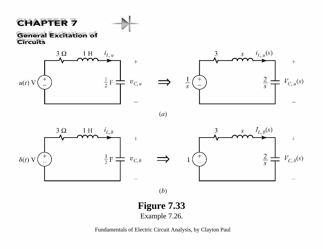
Figure 7.33Example 7.26.
Fundamentals of Electric Circuit Analysis, by Clayton Paul
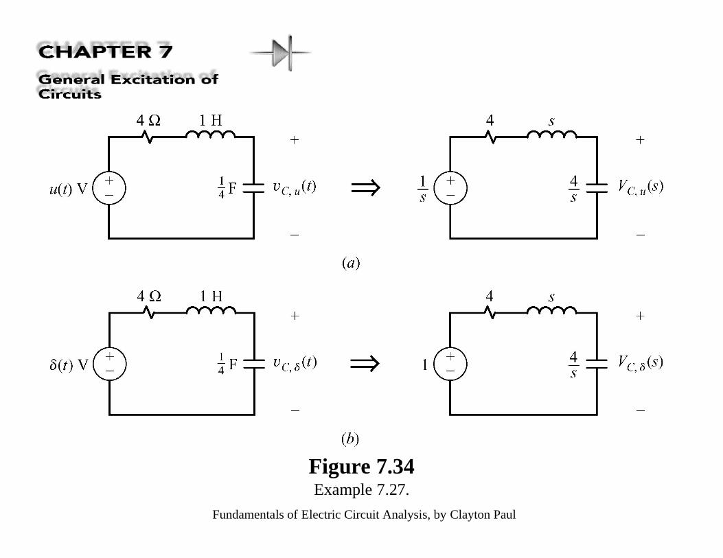
Figure 7.34Example 7.27.
Fundamentals of Electric Circuit Analysis, by Clayton Paul
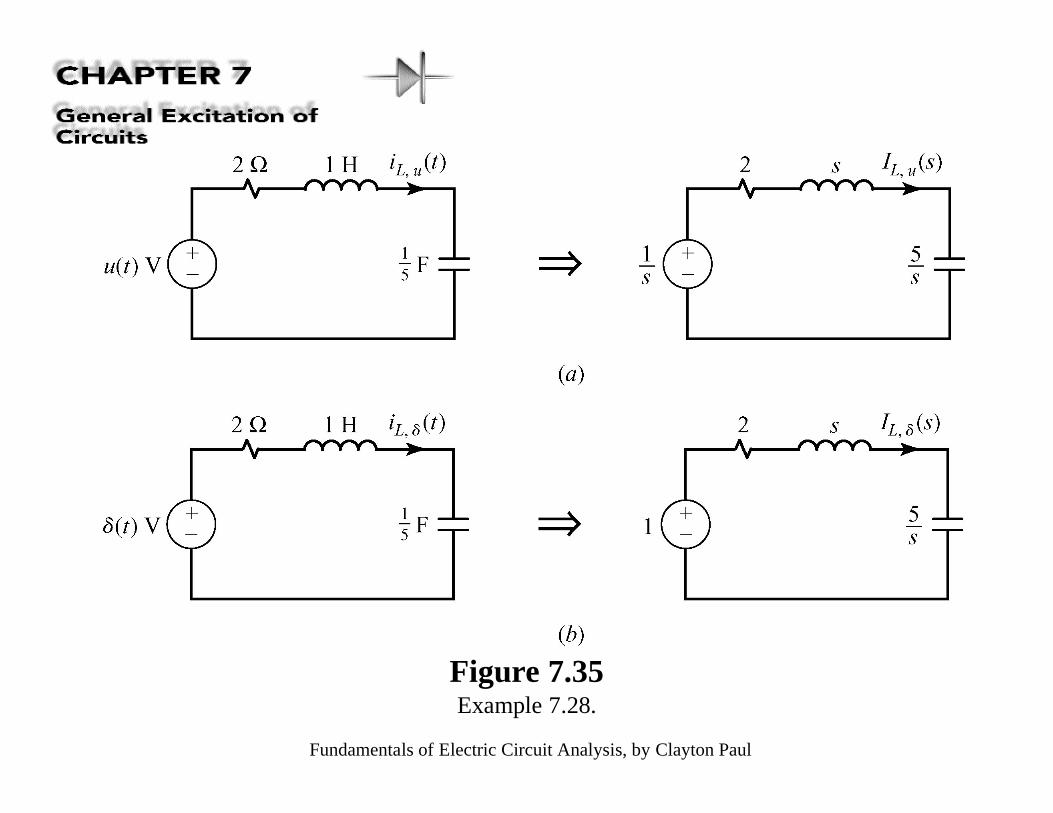
Figure 7.35Example 7.28.
Fundamentals of Electric Circuit Analysis, by Clayton Paul
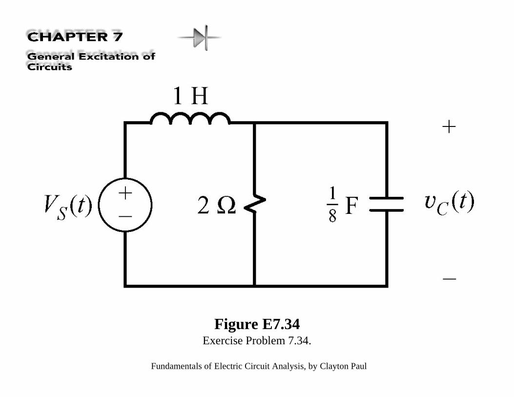
Figure E7.34Exercise Problem 7.34.
Fundamentals of Electric Circuit Analysis, by Clayton Paul
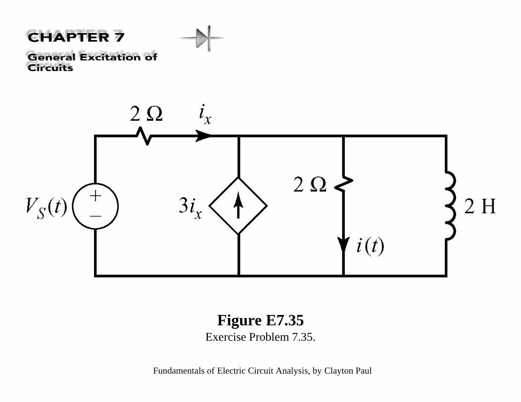
Figure E7.35Exercise Problem 7.35.

Fundamentals of Electric Circuit Analysis, by Clayton Paul
Figure 7.36Example 7.29.
Fundamentals of Electric Circuit Analysis, by Clayton Paul
Figure 7.37Example 7.30.
Fundamentals of Electric Circuit Analysis, by Clayton Paul
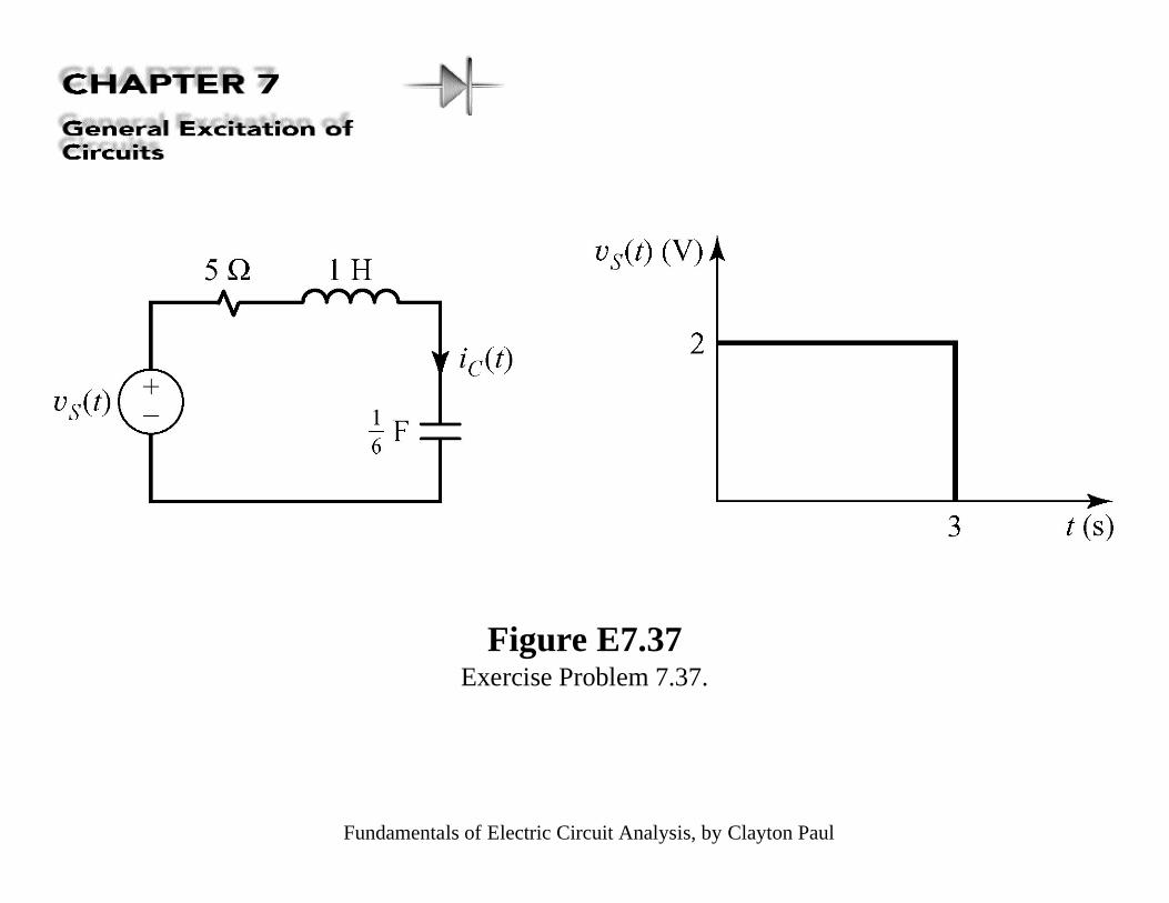
Figure E7.37Exercise Problem 7.37.
Fundamentals of Electric Circuit Analysis, by Clayton Paul
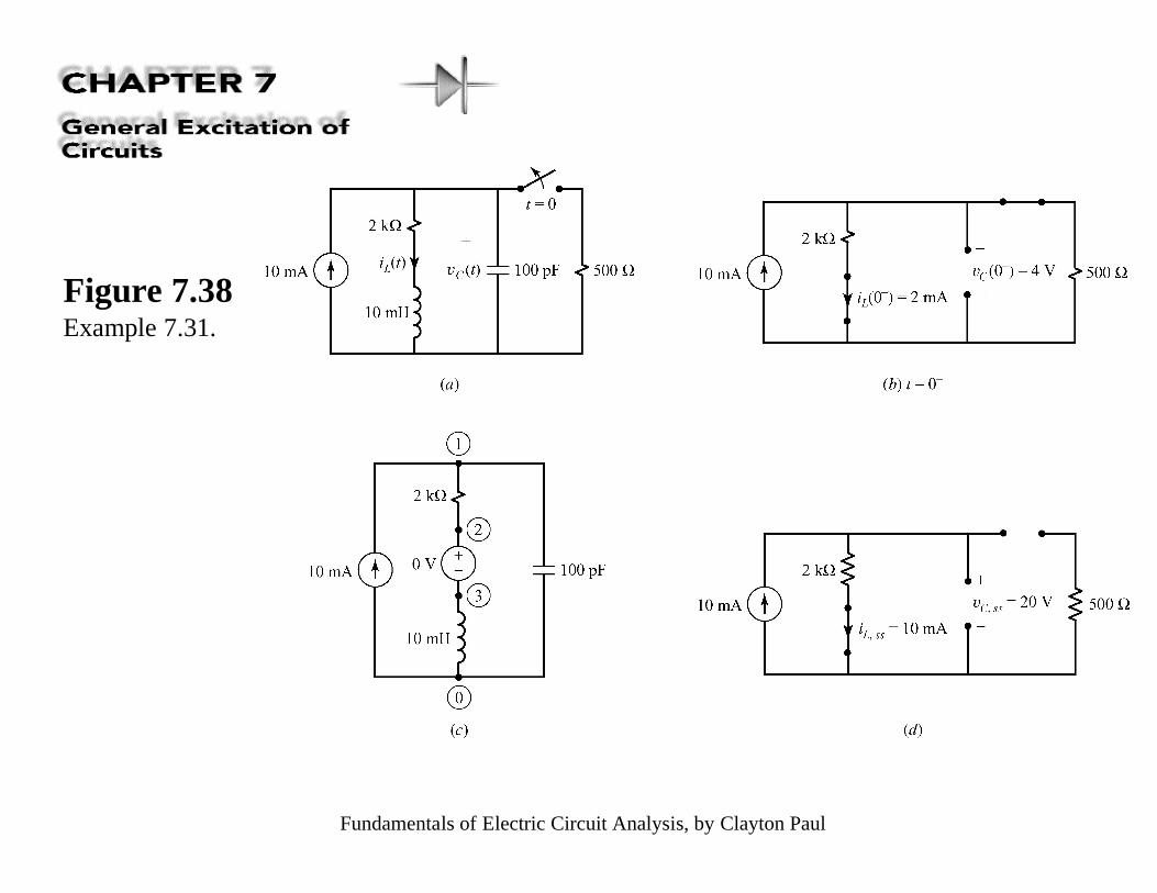
Figure 7.38Example 7.31.
Fundamentals of Electric Circuit Analysis, by Clayton Paul
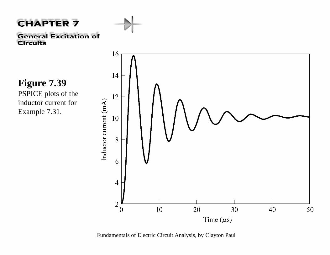
Figure 7.39PSPICE plots of theinductor current forExample 7.31.
Fundamentals of Electric Circuit Analysis, by Clayton Paul
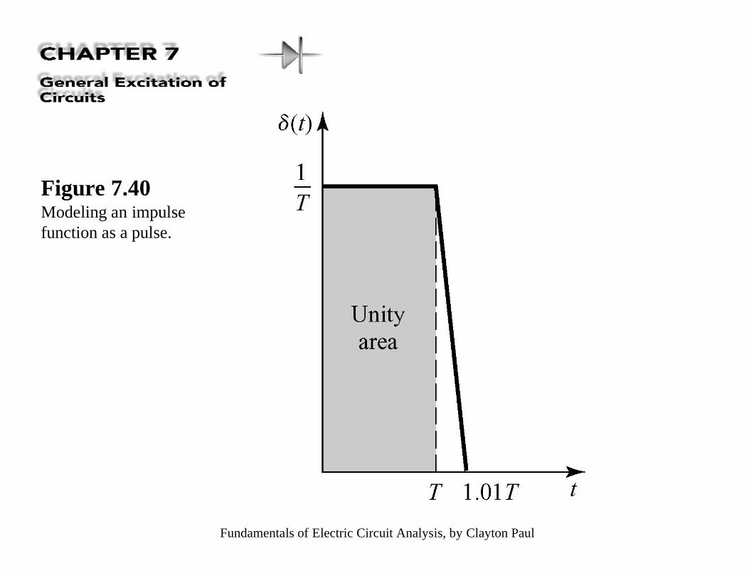
Figure 7.40Modeling an impulsefunction as a pulse.
Fundamentals of Electric Circuit Analysis, by Clayton Paul
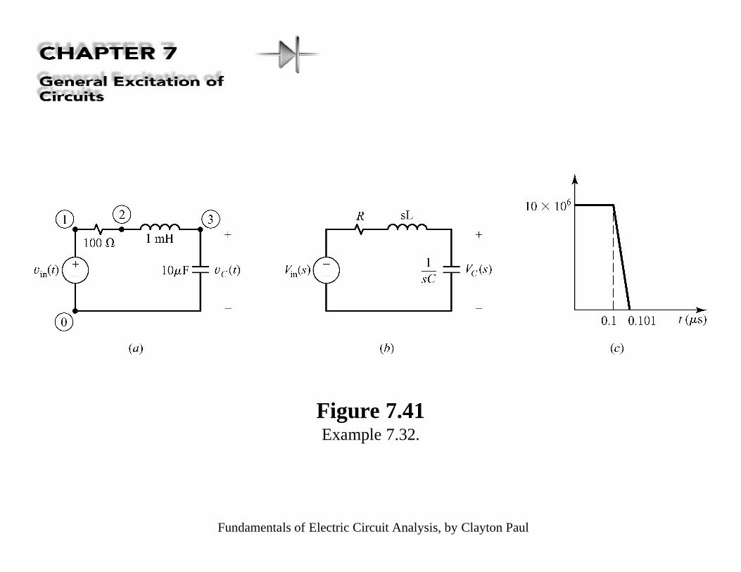
Figure 7.41Example 7.32.
Fundamentals of Electric Circuit Analysis, by Clayton Paul
Figure 7.42Results for the capacitorvoltage in Example 7.32:(a) unit step response,(b) unit impulse response,and (c) unit impulseresponse showing thebeginning time behavior.
Fundamentals of Electric Circuit Analysis, by Clayton Paul
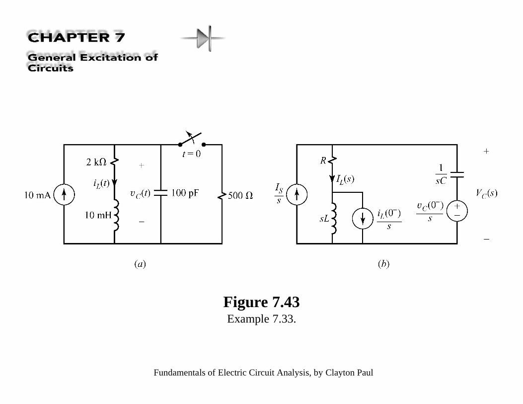
Figure 7.43Example 7.33.
Fundamentals of Electric Circuit Analysis, by Clayton Paul
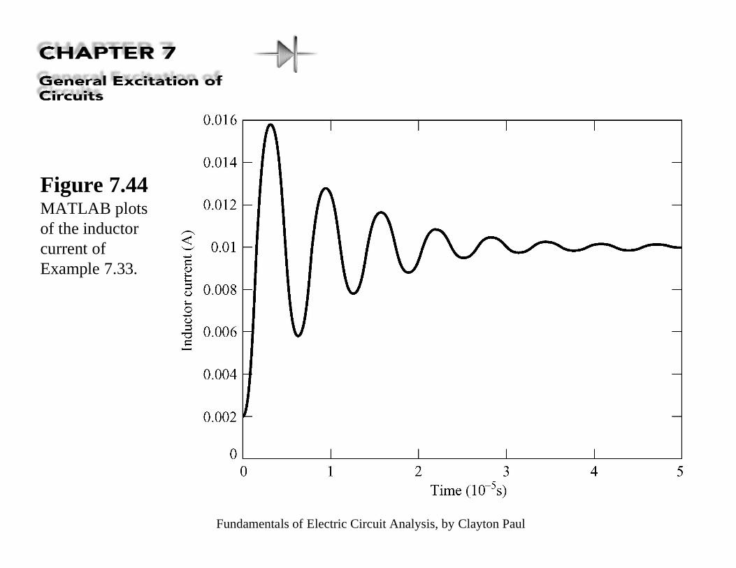
Figure 7.44MATLAB plotsof the inductorcurrent ofExample 7.33.
Fundamentals of Electric Circuit Analysis, by Clayton Paul
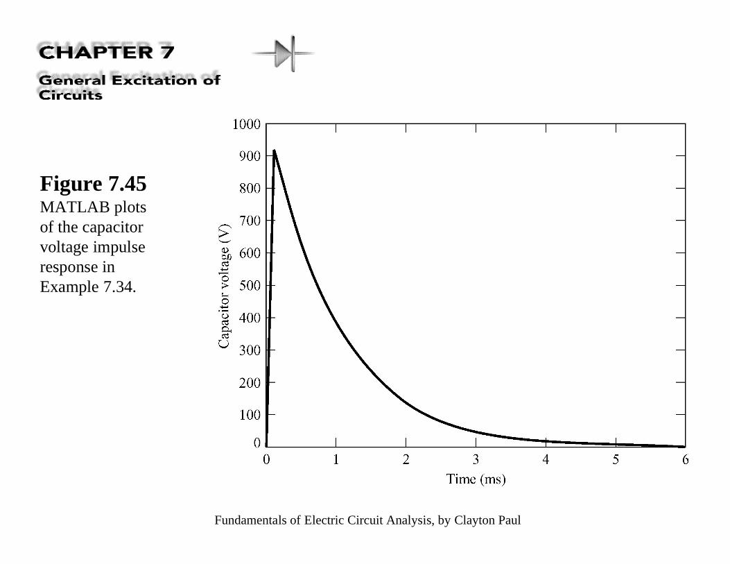
Figure 7.45MATLAB plotsof the capacitorvoltage impulseresponse inExample 7.34.
Fundamentals of Electric Circuit Analysis, by Clayton Paul
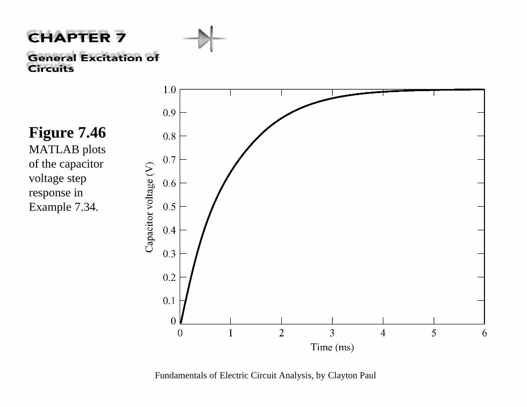
Figure 7.46MATLAB plotsof the capacitorvoltage stepresponse inExample 7.34.
Fundamentals of Electric Circuit Analysis, by Clayton Paul
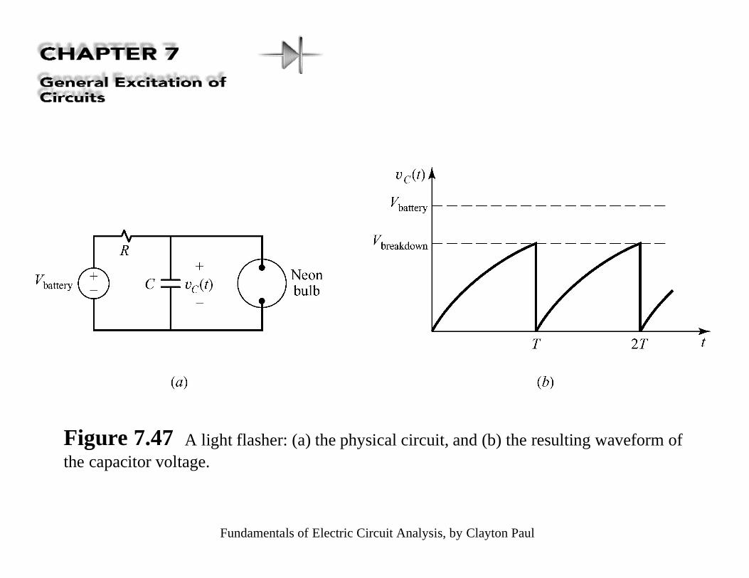
Figure 7.47 A light flasher: (a) the physical circuit, and (b) the resulting waveform ofthe capacitor voltage.
Fundamentals of Electric Circuit Analysis, by Clayton Paul
Figure 7.48Illustration of theeffect of aconnection cable’scapacitance andinductance on thetransmittedwaveforms: (a)the physicalcircuit, (b) anequivalent circuit,(c) the Laplacetransformedcircuit, and (d )the PSPICE nodelabeling.
Fundamentals of Electric Circuit Analysis, by Clayton Paul
Figure 7.49The PSPICEsimulation of the loadvoltage of the circuitin Fig. 7.48 Showing(a) the ringing forR=0Ω caused by thecable’s capacitanceand inductance, andthe load voltage for(b) R=100Ω, and (c)R=250Ω.
Fundamentals of Electric Circuit Analysis, by Clayton Paul
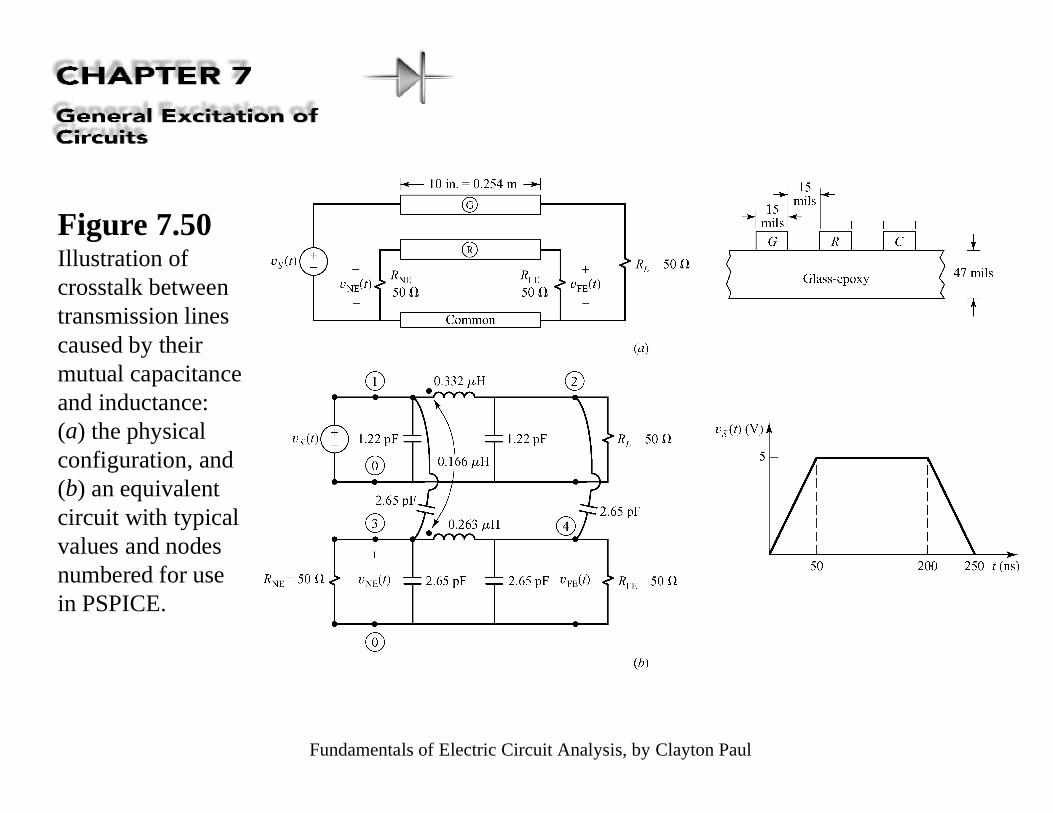
Figure 7.50Illustration ofcrosstalk betweentransmission linescaused by theirmutual capacitanceand inductance:(a) the physicalconfiguration, and(b) an equivalentcircuit with typicalvalues and nodesnumbered for usein PSPICE.
Fundamentals of Electric Circuit Analysis, by Clayton Paul
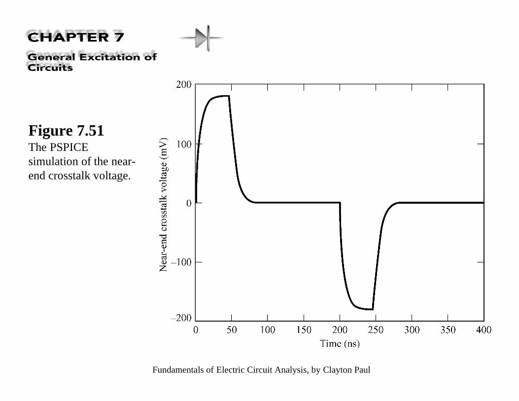
Figure 7.51The PSPICEsimulation of the near-end crosstalk voltage.
Fundamentals of Electric Circuit Analysis, by Clayton Paul
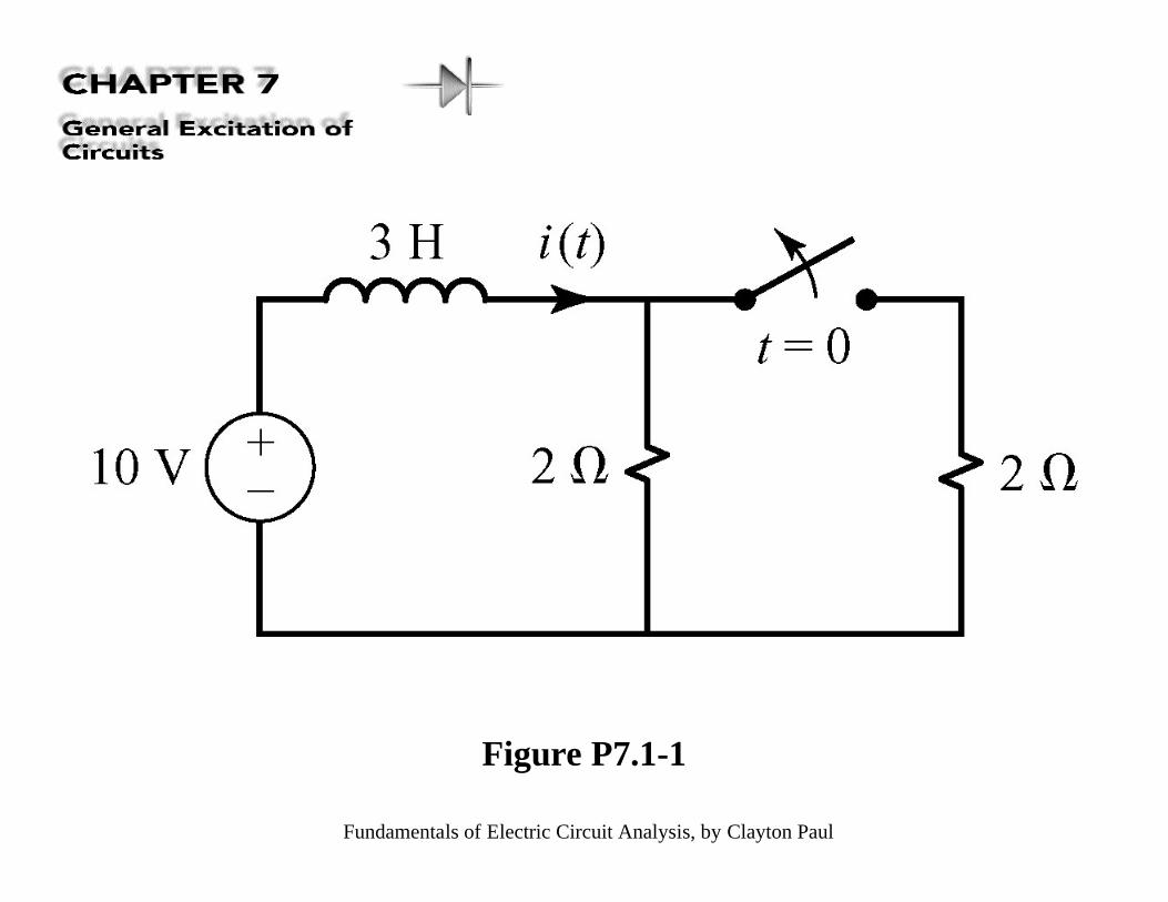
Figure P7.1-1
Fundamentals of Electric Circuit Analysis, by Clayton Paul
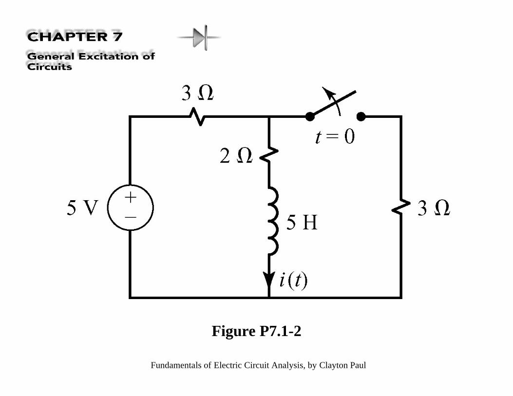
Figure P7.1-2
Fundamentals of Electric Circuit Analysis, by Clayton Paul
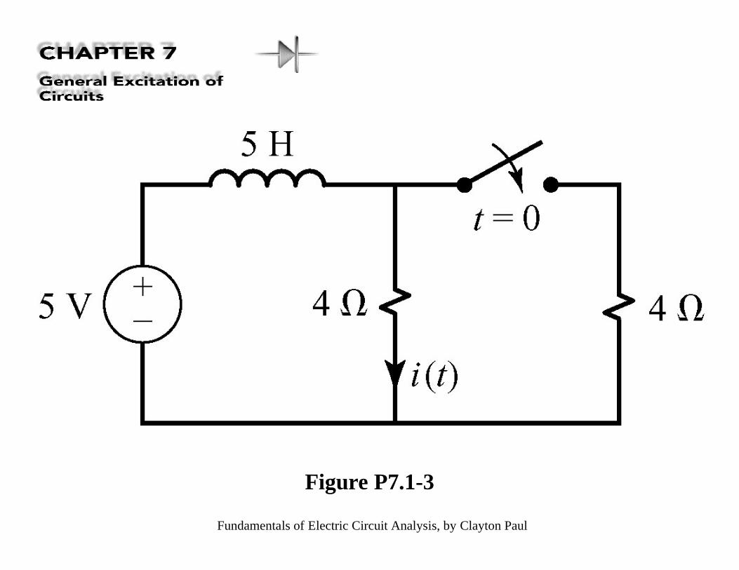
Figure P7.1-3
Fundamentals of Electric Circuit Analysis, by Clayton Paul
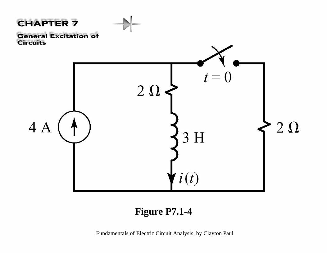
Figure P7.1-4
Fundamentals of Electric Circuit Analysis, by Clayton Paul
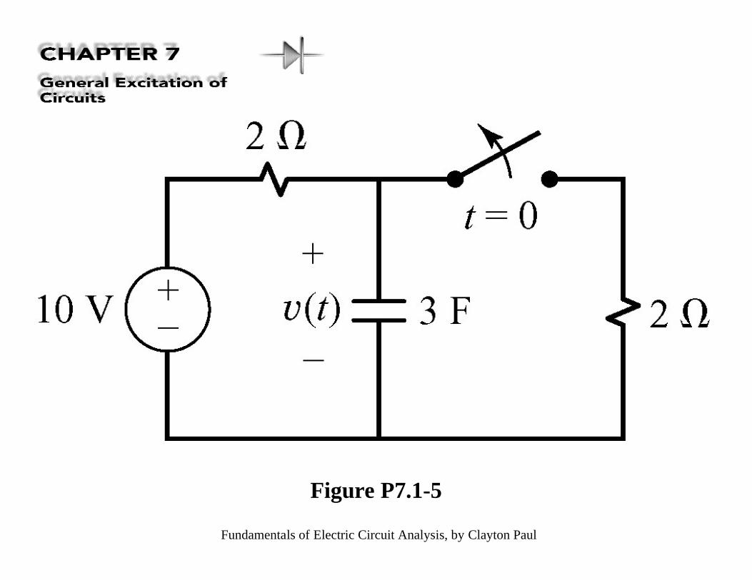
Figure P7.1-5
Fundamentals of Electric Circuit Analysis, by Clayton Paul
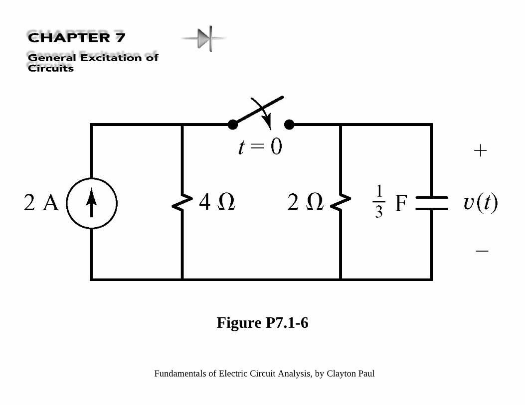
Figure P7.1-6
Fundamentals of Electric Circuit Analysis, by Clayton Paul
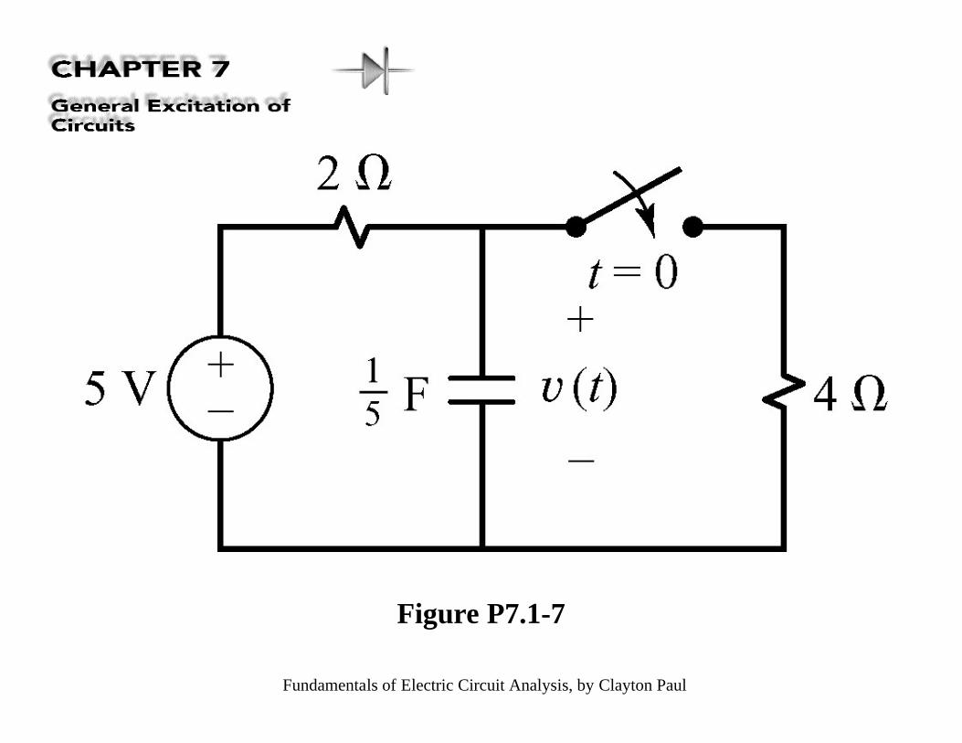
Figure P7.1-7
Fundamentals of Electric Circuit Analysis, by Clayton Paul
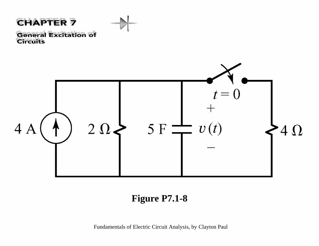
Figure P7.1-8
Fundamentals of Electric Circuit Analysis, by Clayton Paul
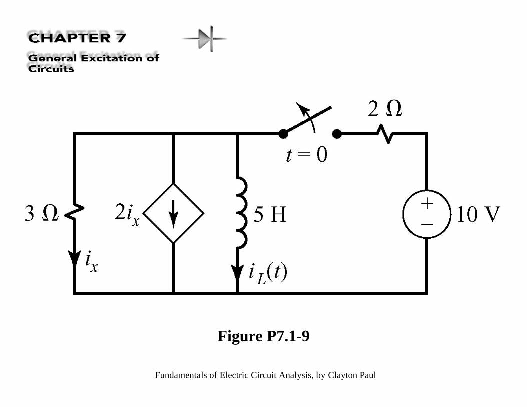
Figure P7.1-9
Fundamentals of Electric Circuit Analysis, by Clayton Paul
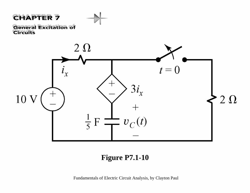
Figure P7.1-10
Fundamentals of Electric Circuit Analysis, by Clayton Paul
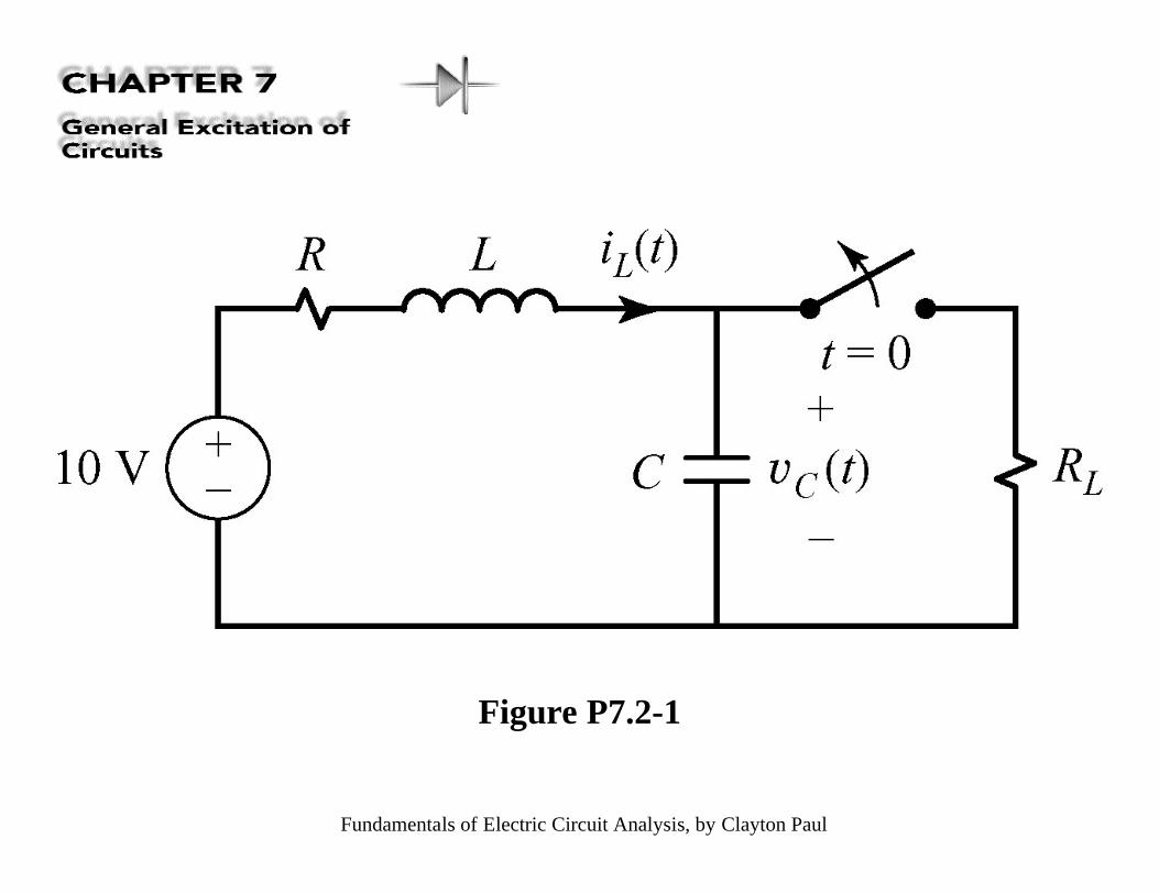
Figure P7.2-1
Fundamentals of Electric Circuit Analysis, by Clayton Paul
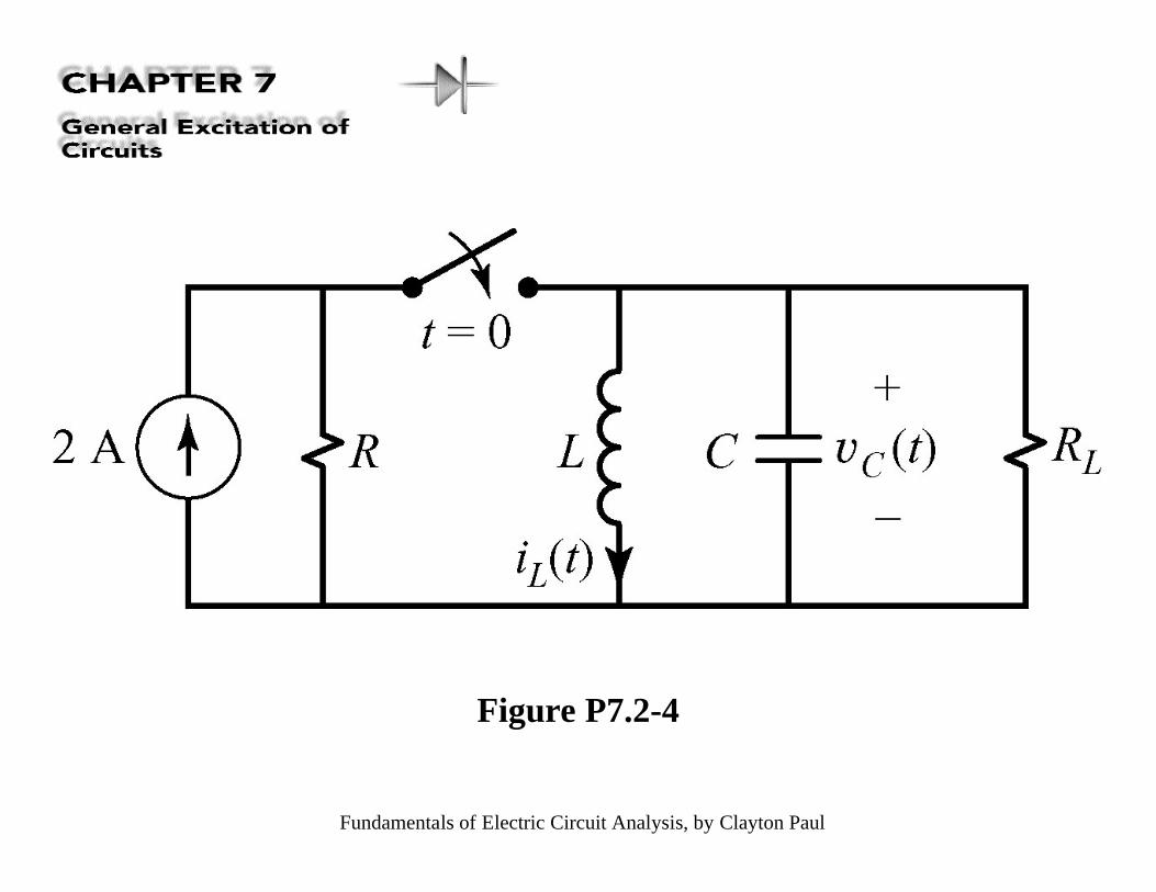
Figure P7.2-4
Fundamentals of Electric Circuit Analysis, by Clayton Paul
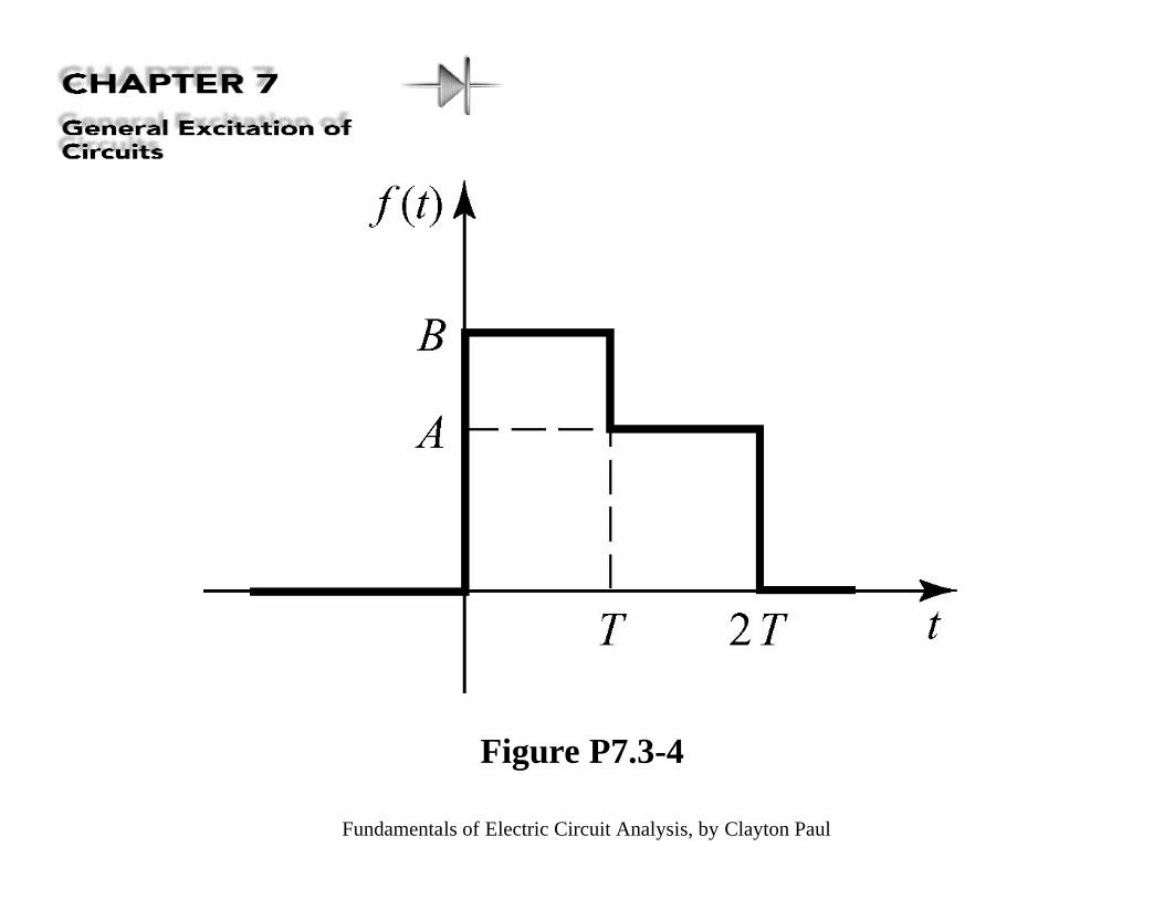
Figure P7.3-4
Fundamentals of Electric Circuit Analysis, by Clayton Paul
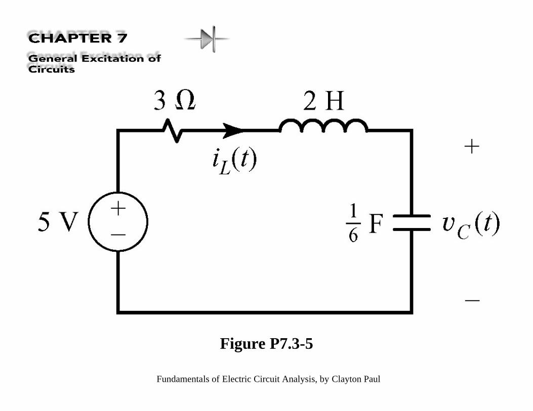
Figure P7.3-5
Fundamentals of Electric Circuit Analysis, by Clayton Paul
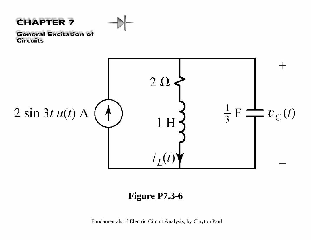
Figure P7.3-6
Fundamentals of Electric Circuit Analysis, by Clayton Paul
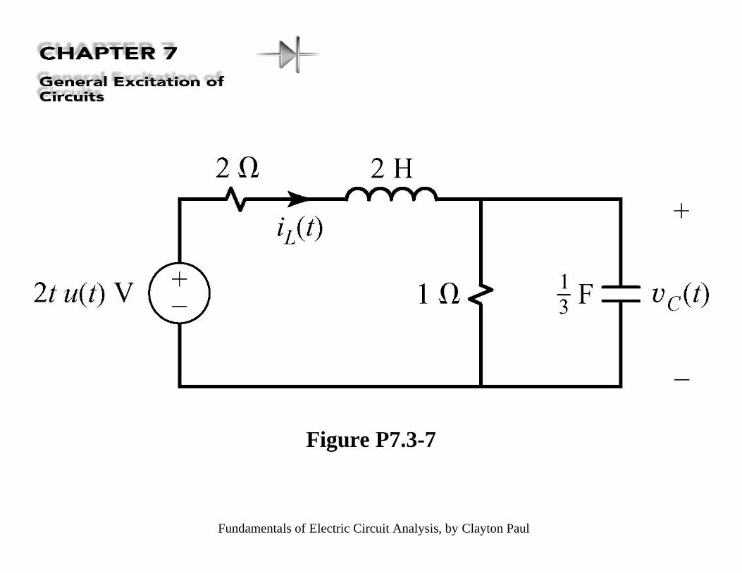
Figure P7.3-7
Fundamentals of Electric Circuit Analysis, by Clayton Paul
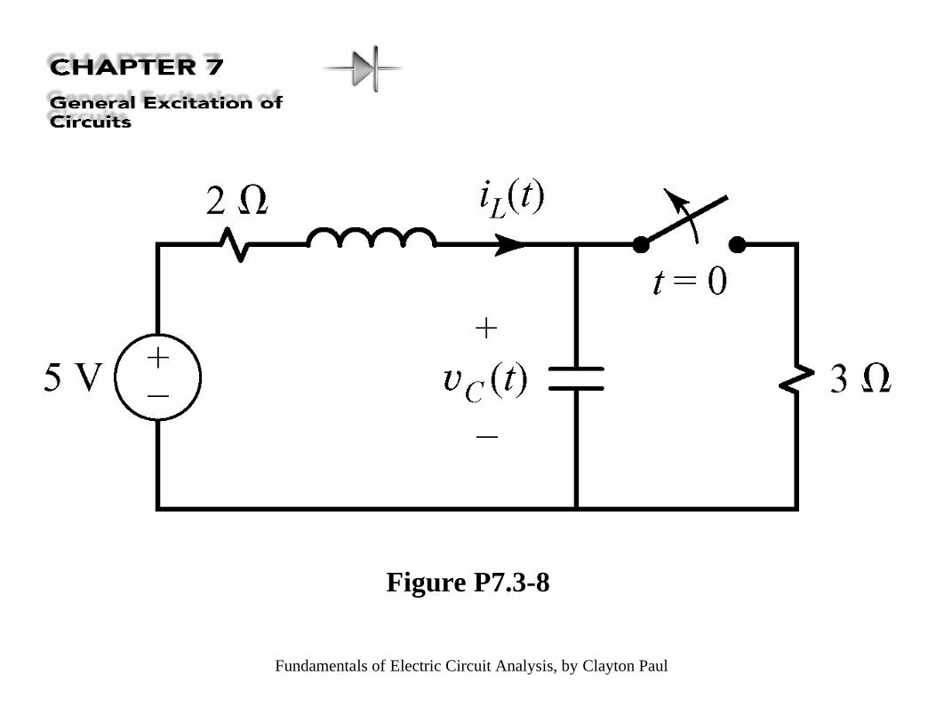
Figure P7.3-8
Fundamentals of Electric Circuit Analysis, by Clayton Paul
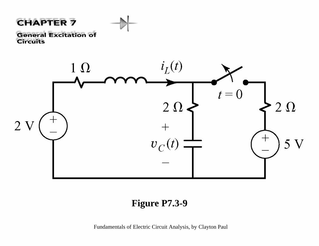
Figure P7.3-9
Fundamentals of Electric Circuit Analysis, by Clayton Paul
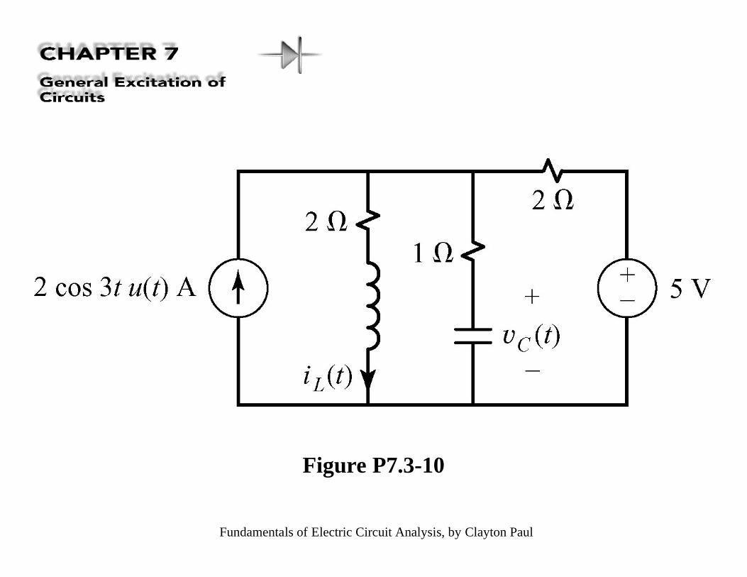
Figure P7.3-10
Fundamentals of Electric Circuit Analysis, by Clayton Paul
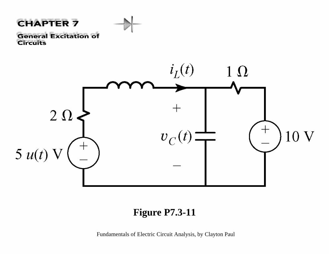
Figure P7.3-11
Fundamentals of Electric Circuit Analysis, by Clayton Paul
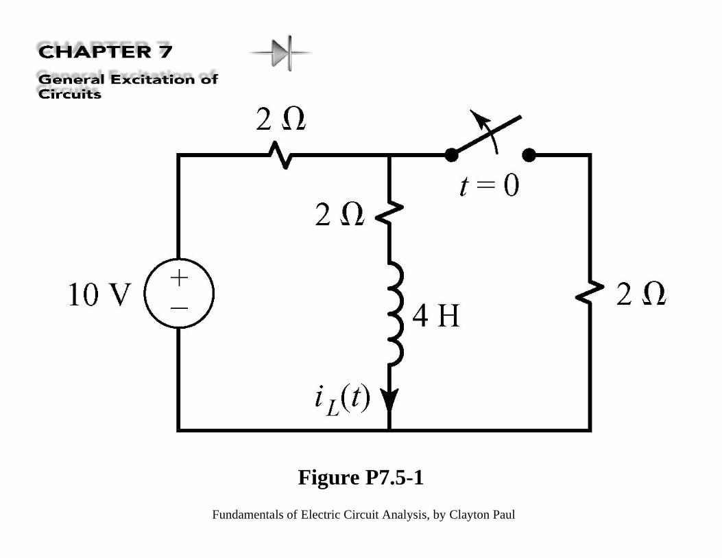
Figure P7.5-1
Fundamentals of Electric Circuit Analysis, by Clayton Paul
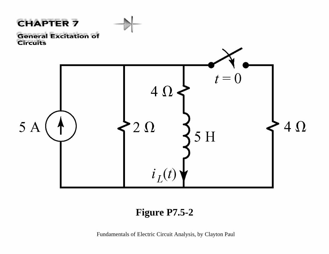
Figure P7.5-2
Fundamentals of Electric Circuit Analysis, by Clayton Paul
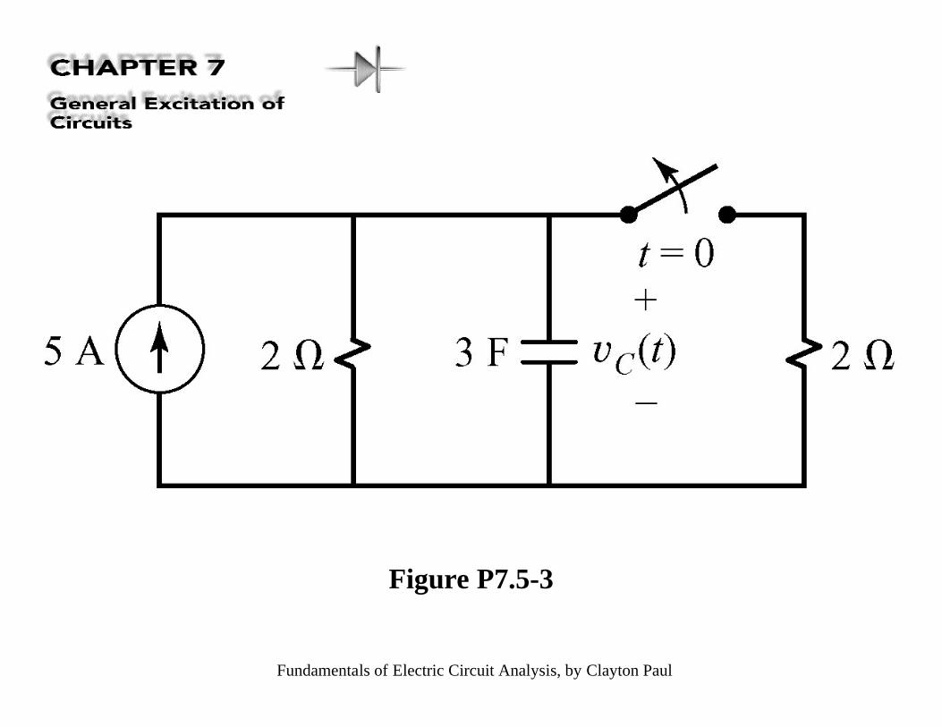
Figure P7.5-3
Fundamentals of Electric Circuit Analysis, by Clayton Paul
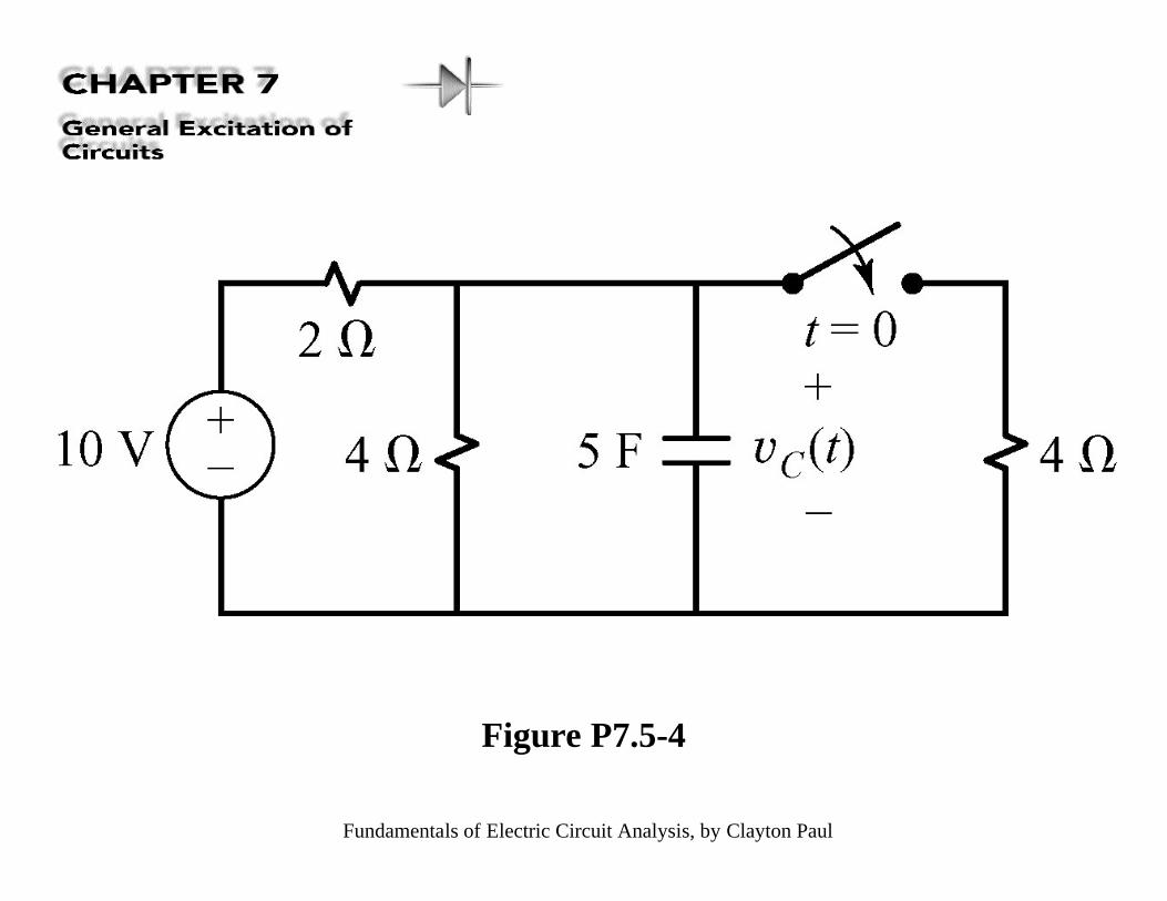
Figure P7.5-4
Fundamentals of Electric Circuit Analysis, by Clayton Paul
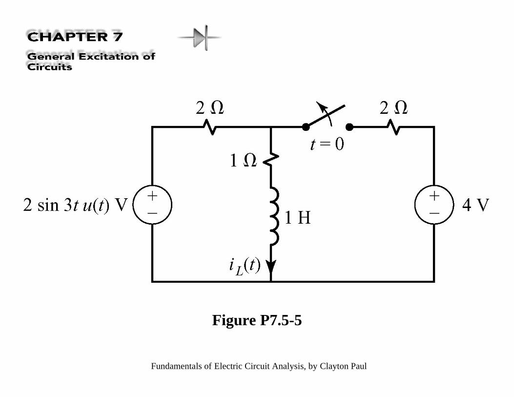
Figure P7.5-5
Fundamentals of Electric Circuit Analysis, by Clayton Paul
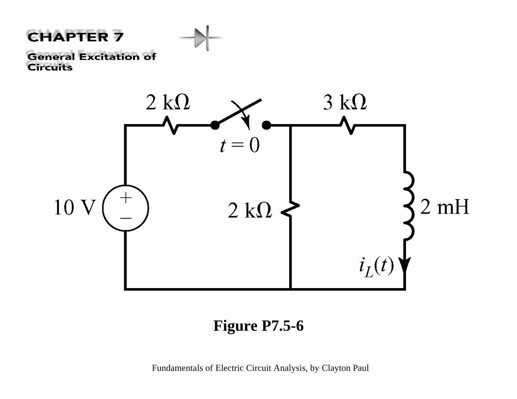
Figure P7.5-6
Fundamentals of Electric Circuit Analysis, by Clayton Paul
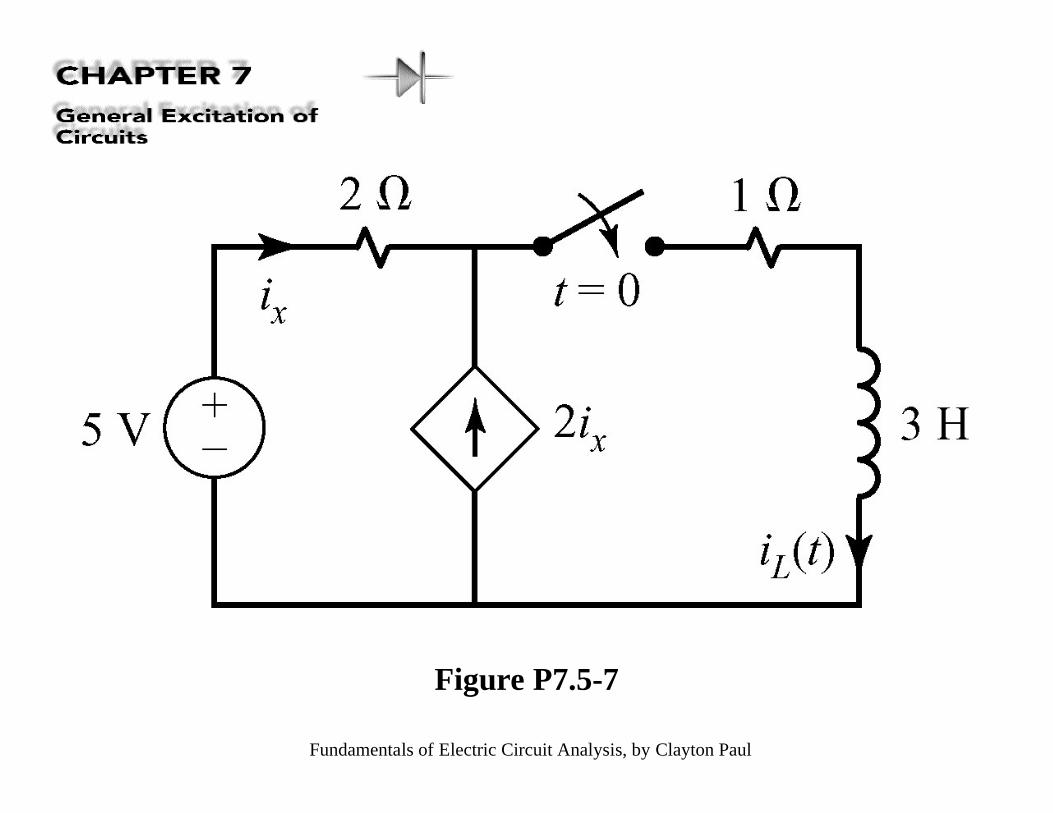
Figure P7.5-7
Fundamentals of Electric Circuit Analysis, by Clayton Paul
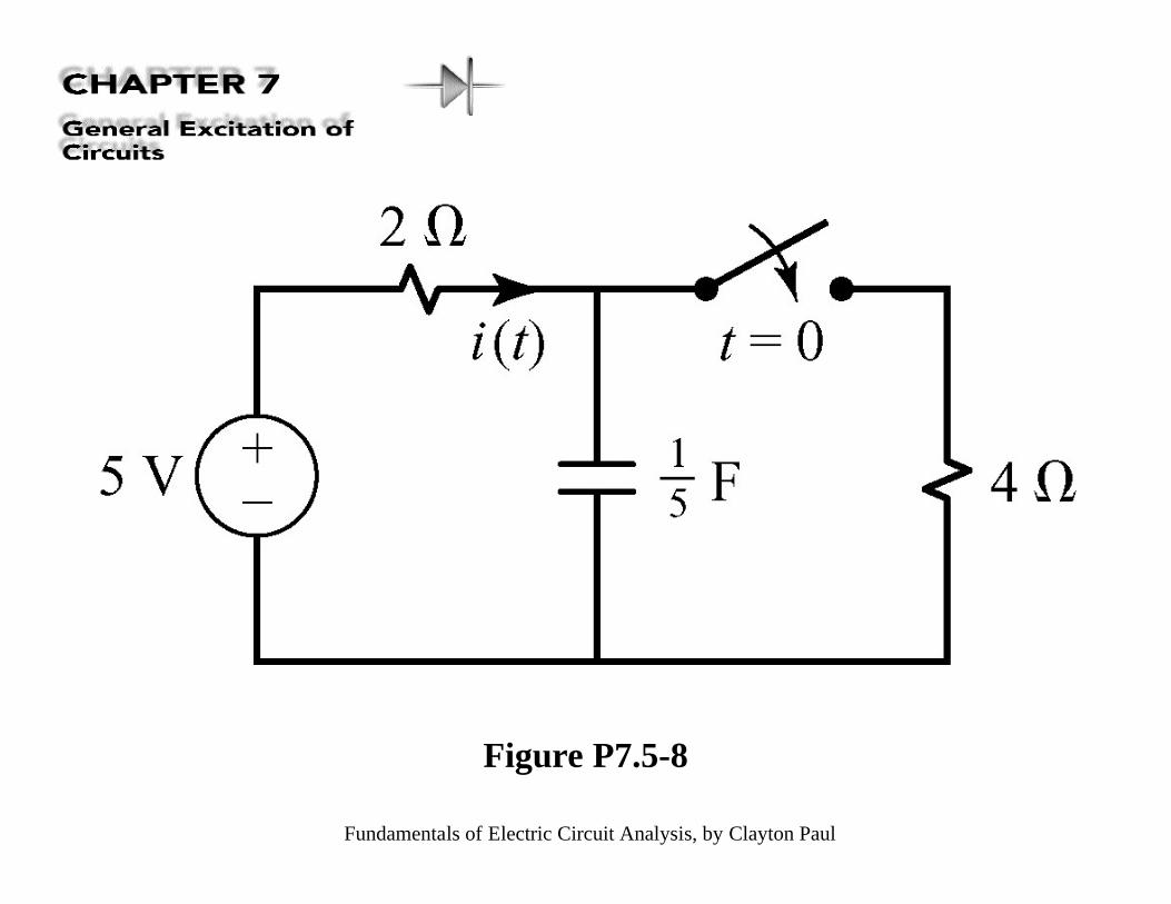
Figure P7.5-8
Fundamentals of Electric Circuit Analysis, by Clayton Paul
Figure P7.5-9
Fundamentals of Electric Circuit Analysis, by Clayton Paul
Figure P7.5-10
Fundamentals of Electric Circuit Analysis, by Clayton Paul
Figure P7.5-11
Fundamentals of Electric Circuit Analysis, by Clayton Paul
Figure P7.5-12
Fundamentals of Electric Circuit Analysis, by Clayton Paul
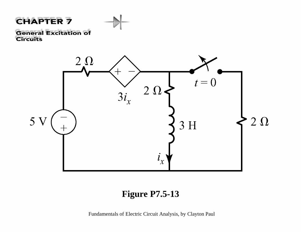
Figure P7.5-13
Fundamentals of Electric Circuit Analysis, by Clayton Paul
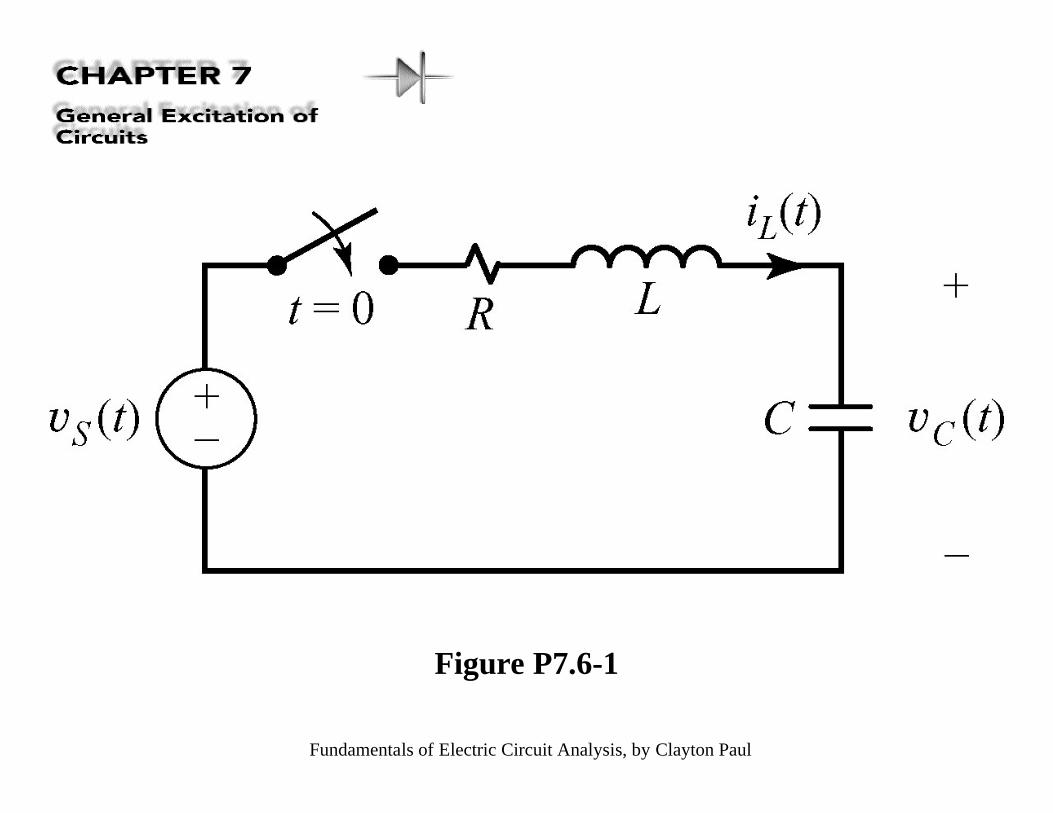
Figure P7.6-1
Fundamentals of Electric Circuit Analysis, by Clayton Paul
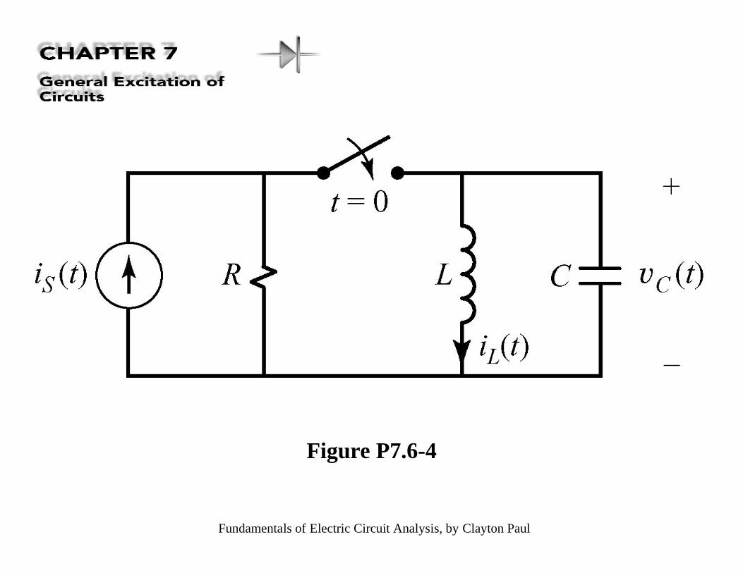
Figure P7.6-4
Fundamentals of Electric Circuit Analysis, by Clayton Paul
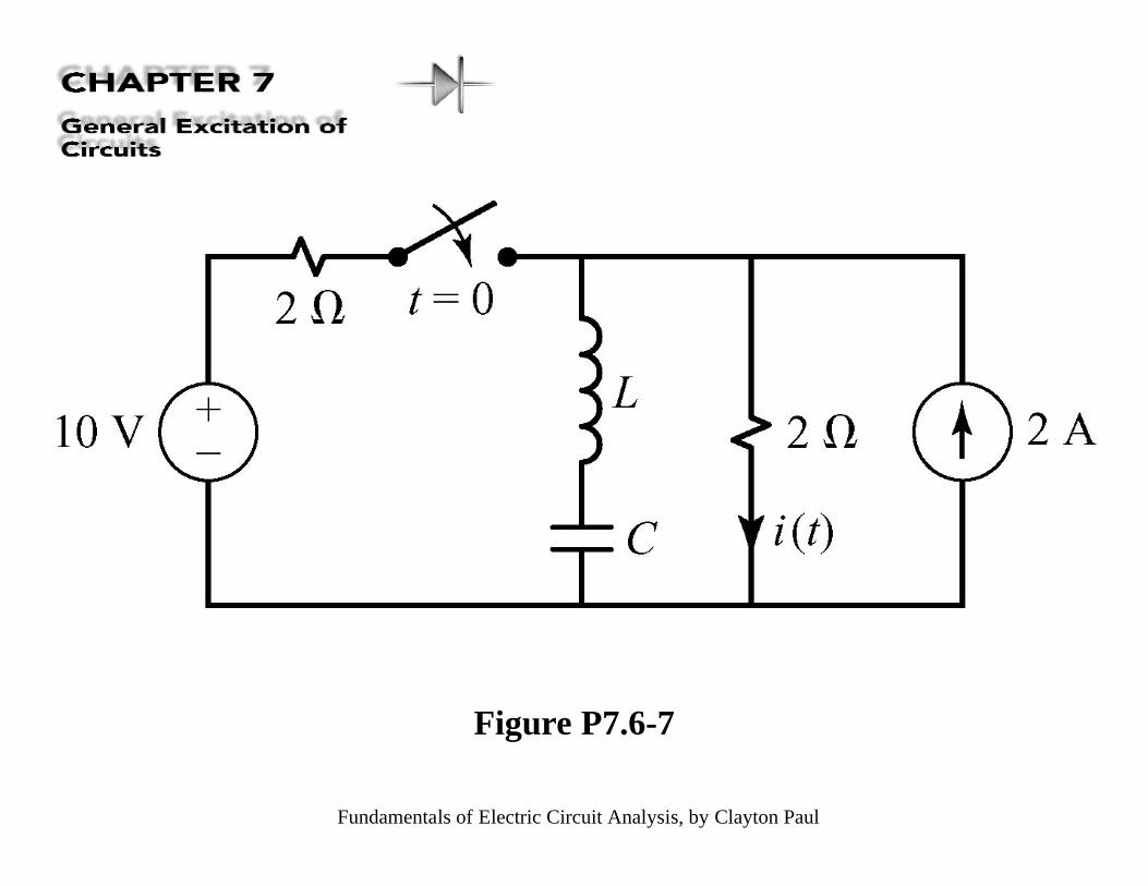
Figure P7.6-7
Fundamentals of Electric Circuit Analysis, by Clayton Paul
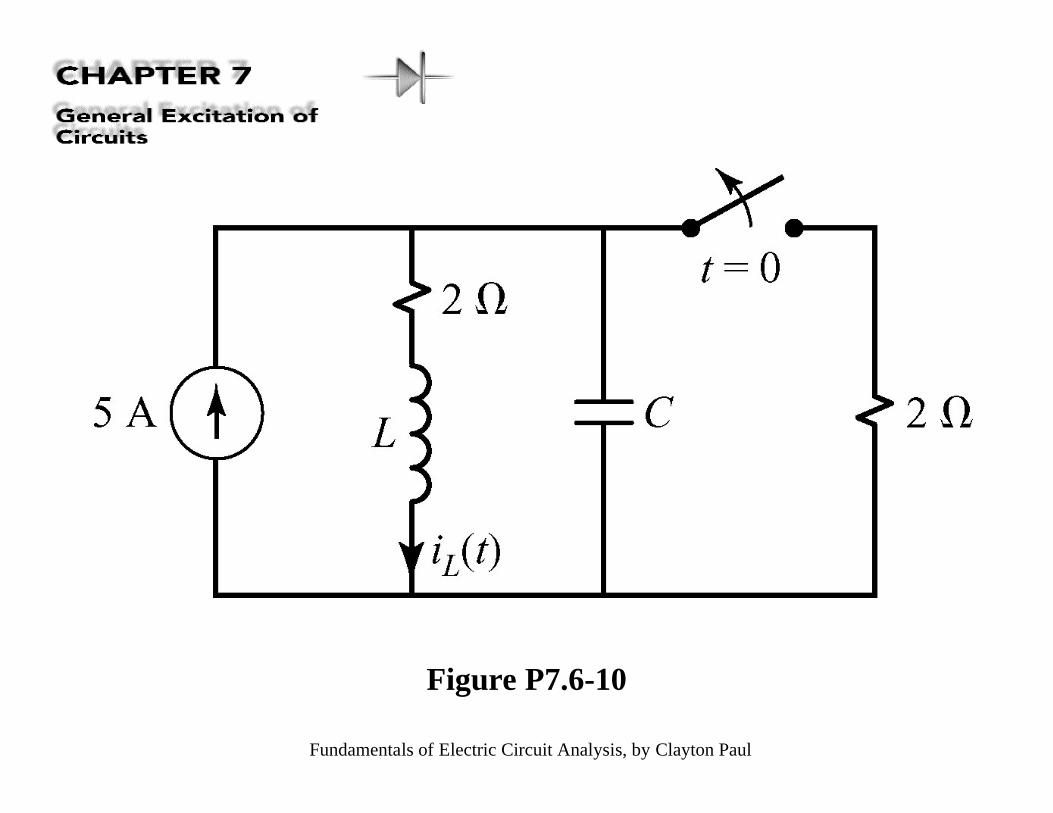
Figure P7.6-10
Fundamentals of Electric Circuit Analysis, by Clayton Paul
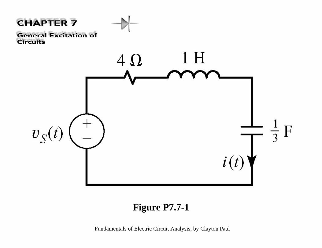
Figure P7.7-1
Fundamentals of Electric Circuit Analysis, by Clayton Paul
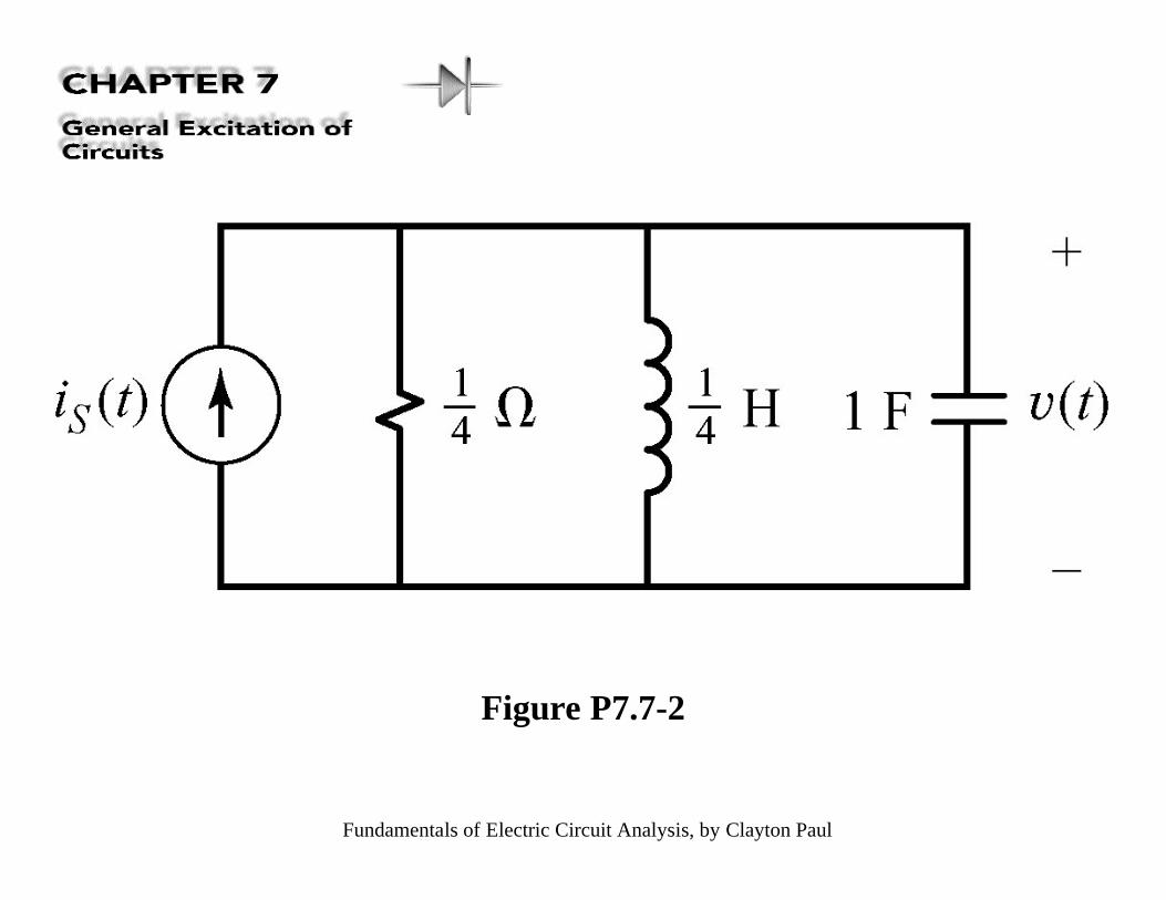
Figure P7.7-2
Fundamentals of Electric Circuit Analysis, by Clayton Paul
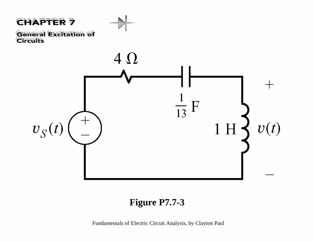
Figure P7.7-3
Fundamentals of Electric Circuit Analysis, by Clayton Paul
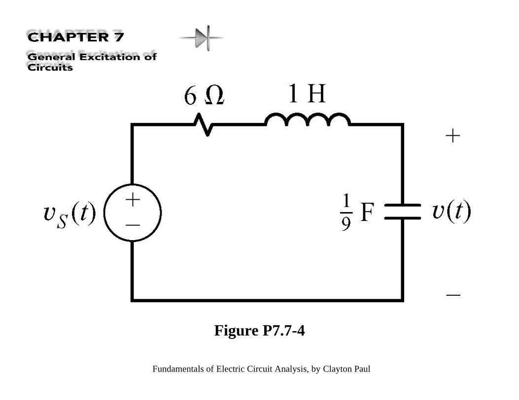
Figure P7.7-4
Fundamentals of Electric Circuit Analysis, by Clayton Paul
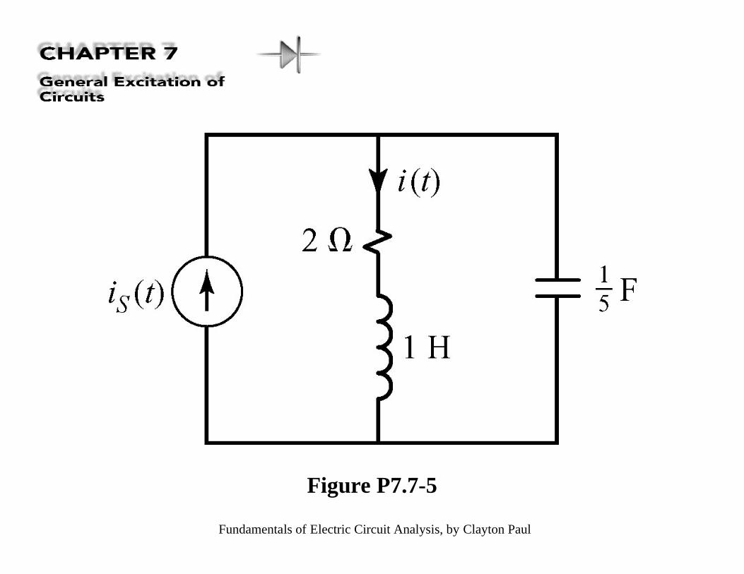
Figure P7.7-5
Fundamentals of Electric Circuit Analysis, by Clayton Paul
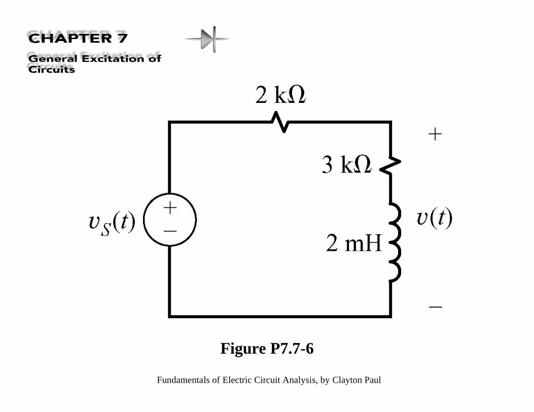
Figure P7.7-6
Fundamentals of Electric Circuit Analysis, by Clayton Paul
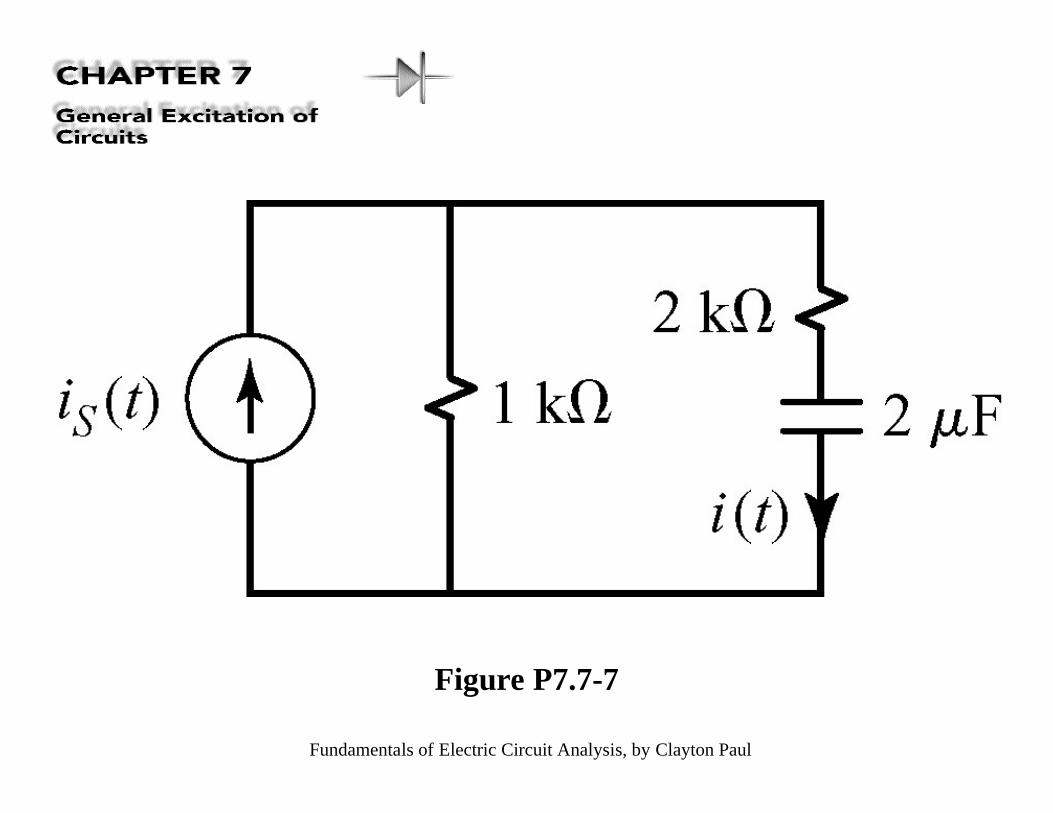
Figure P7.7-7
Fundamentals of Electric Circuit Analysis, by Clayton Paul
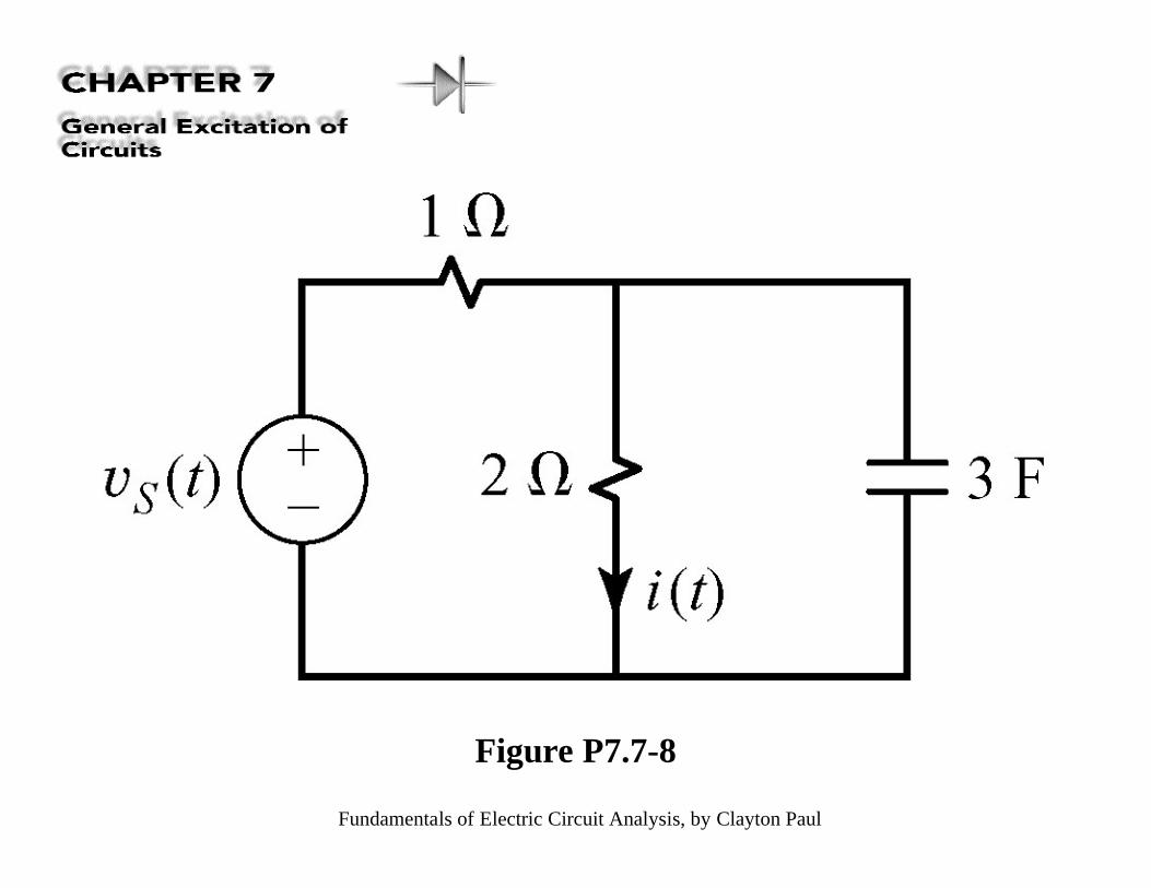
Figure P7.7-8

Fundamentals of Electric Circuit Analysis, by Clayton Paul
Figure P7.7-9
Fundamentals of Electric Circuit Analysis, by Clayton Paul
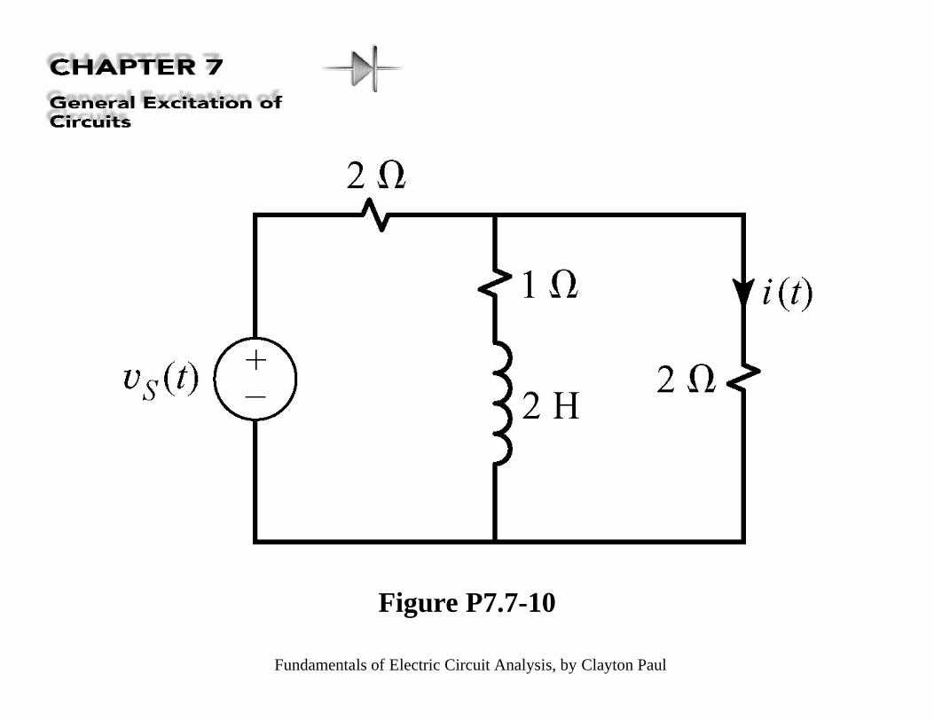
Figure P7.7-10
Fundamentals of Electric Circuit Analysis, by Clayton Paul
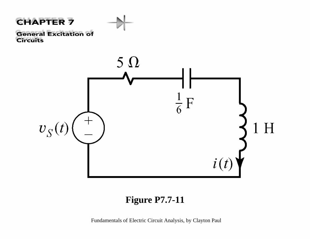
Figure P7.7-11
Fundamentals of Electric Circuit Analysis, by Clayton Paul
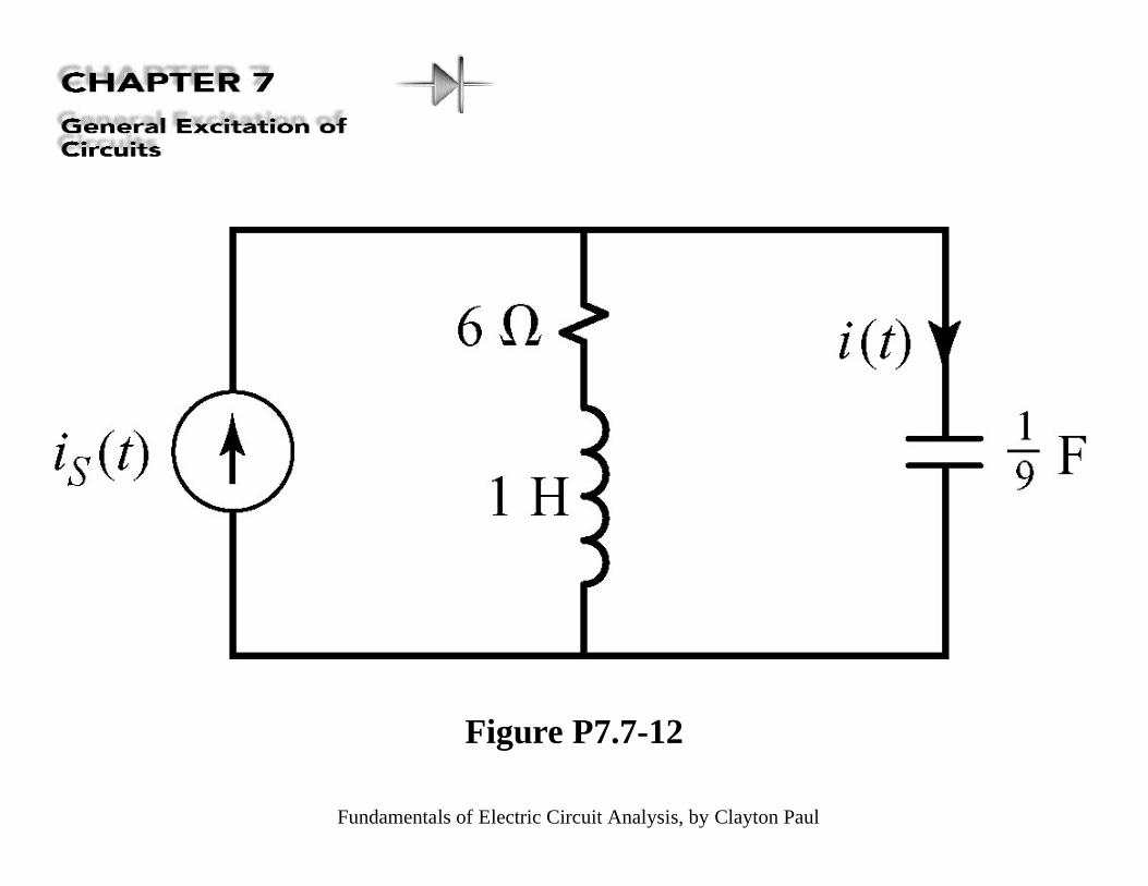
Figure P7.7-12
Fundamentals of Electric Circuit Analysis, by Clayton Paul
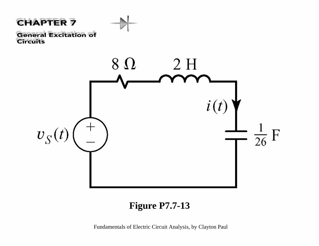
Figure P7.7-13
Fundamentals of Electric Circuit Analysis, by Clayton Paul
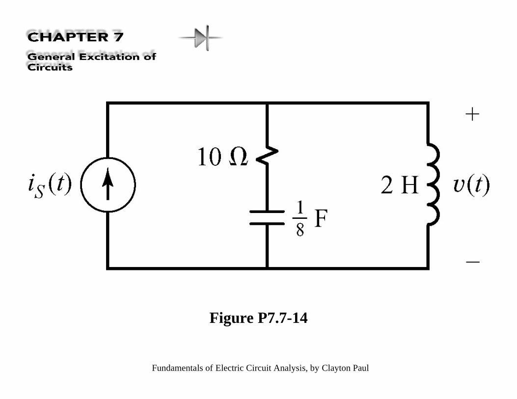
Figure P7.7-14
Fundamentals of Electric Circuit Analysis, by Clayton Paul
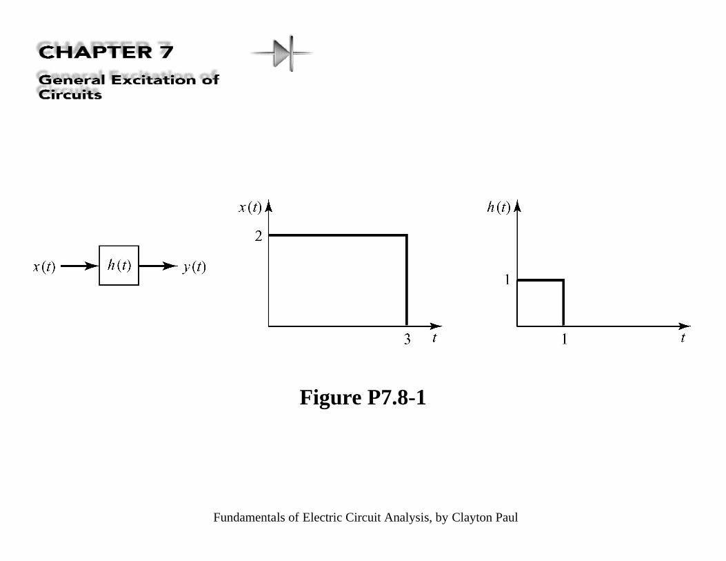
Figure P7.8-1
Fundamentals of Electric Circuit Analysis, by Clayton Paul
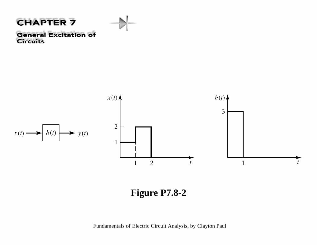
Figure P7.8-2
Fundamentals of Electric Circuit Analysis, by Clayton Paul
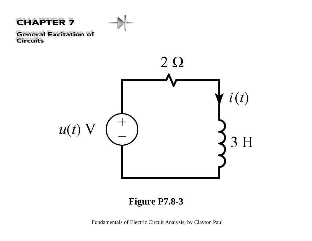
Figure P7.8-3
Fundamentals of Electric Circuit Analysis, by Clayton Paul
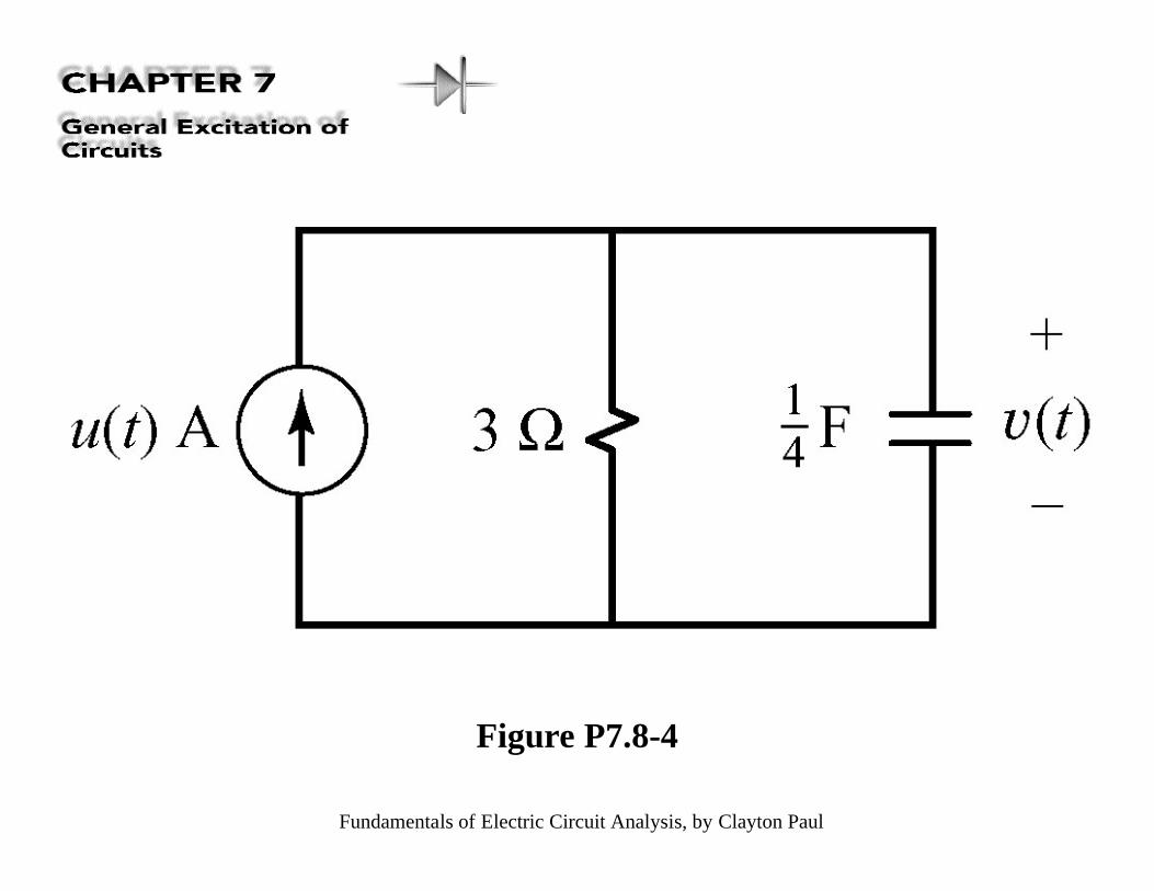
Figure P7.8-4
Fundamentals of Electric Circuit Analysis, by Clayton Paul
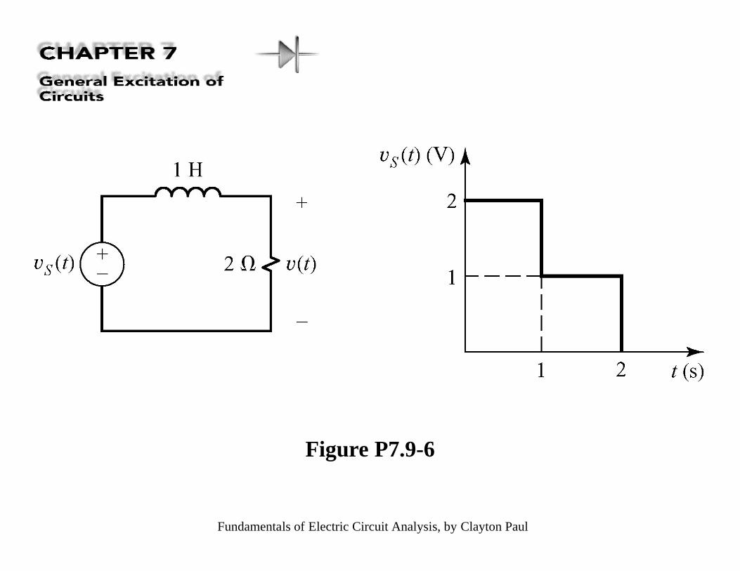
Figure P7.9-6
Fundamentals of Electric Circuit Analysis, by Clayton Paul
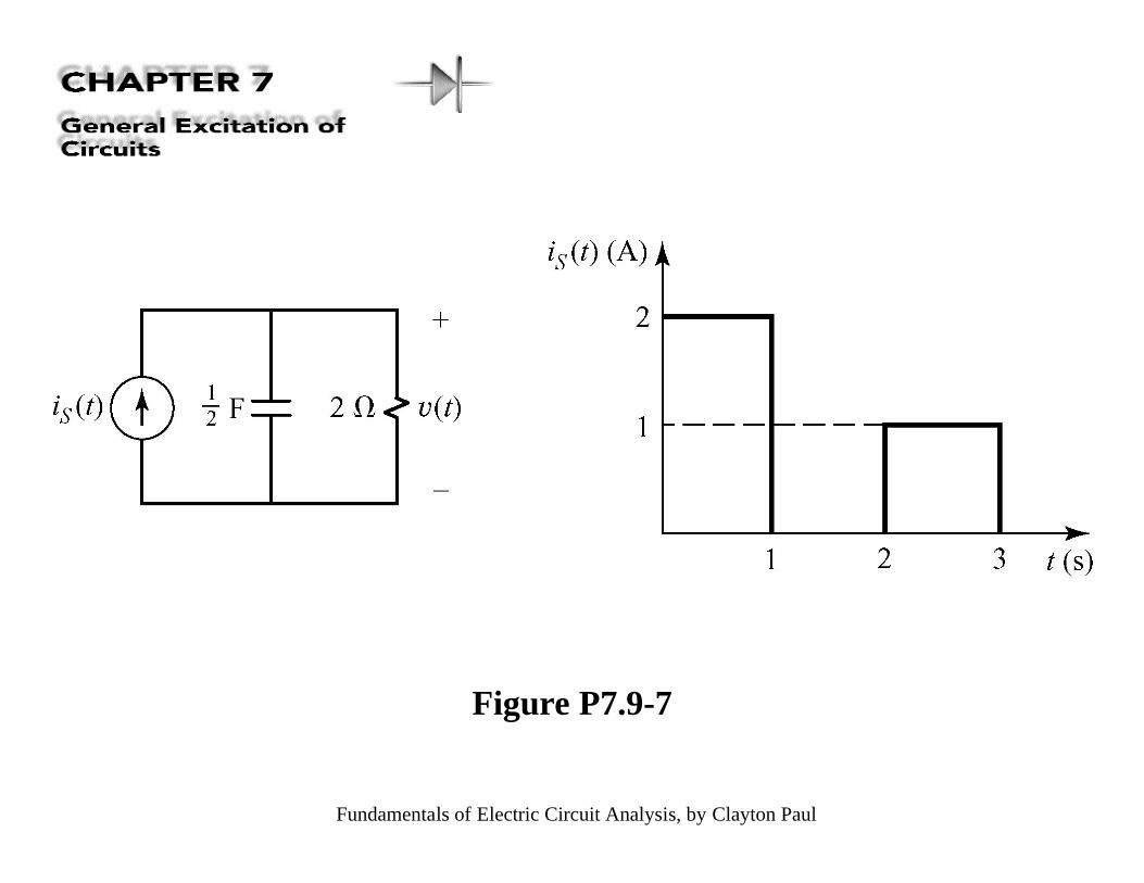
Figure P7.9-7