Embed Size (px)
Citation preview

32nd URSI GASS, Montreal, 19-26 August 2017
Field Distributions of the Hybrid Modes in Rectangular Waveguides Filled with Uniaxial Media
with Tilted Optic Axis Lying in Sidewall Planes
Kepei Sun(1) and Jay K. Lee(1) and Jennifer W. Graham(1)
(1) Syracuse University, Syracuse, NY, 13244, http://www.syracuse.edu
Abstract The field distributions of various modes in rectangular waveguides filled with uniaxial media are presented. The presented cases include aligned cases when the optic axis is parallel to one of the coordinate axes and the tilted cases when the optic axis is not parallel to any of the coordinate axes but still lies within one of the two side-wall planes. In the aligned uniaxial-z case the analytical solution is compared with the results of the dyadic green’s functions (DGF). In other aligned cases the field distributions of selected extra-ordinary wave modes are also plotted and to be compared with the isotropic case. In the tilted cases, the field distributions of the hybrid modes which are coupled ordinary-waves and extra-ordinary waves show asymmetry which is not seen in the aligned cases and isotropic case. The validity of the hybrid mode field plots are verified by comparing a limiting tilted case with analytical solutions of an aligned case. 1. Introduction Recently, the field and wave mode behaviors in a rectangular waveguide filled with uniaxial media have been studied comprehensively in [1]. Various orientations of the optic axis of the uniaxial medium were considered and summarized. In terms of the two characteristic wave modes in uniaxial media, the ordinary wave (o-wave) and extra-ordinary wave (e-wave) are decoupled in aligned cases, whereas they are coupled to support travelling hybrid modes in tilted cases. A new computational algorithm was proposed for calculating the wave numbers of the hybrid modes when the optic axis is tilted and lying in one of the two sidewall planes. Compared with conventional spectral domain analysis methods, this new algorithm avoids the complexity of the convergence problem. The method takes advantage of the commonality in computing similar problems with different parameters and thus saves computational time when solving a large number of problems with different configurations. For example, dominant hybrid mode behaviors affected by the level of uniaxial anisotropy, tilting angle and waveguide dimensions have been discussed in [2], where all the results discussed are computed using the proposed algorithm in [1]. One can acquire physical interpretation of how each factor would affect the hybrid mode by understanding the presented curves in [2]. This paper aims to provide more insight into the field solutions, in addition to the previously demonstrated wave
mode behaviors. Specifically, we shall use the same examples shown in [1] and [2]. 2. Aligned Cases The aligned cases include three sub-cases with the optic axis parallel to x, y or z axis. The dyadic Green’s functions for the uniaxial-z case were obtained in [3] and field distributions for TMz31 mode (a e-wave mode) were demonstrated. The same results can be also obtained using the analytical solutions from the methods presented in [4]. Figure 1 shows the field plotting results of the analytical solutions that yield the same results with the dyadic Green’s function.
Figure 1. Field magnitude distributions for TMz31 mode over the waveguide cross-section in uniaxial-z case.
Figure 2. Field magnitude distributions for TMx31 mode over the waveguide cross-section in uniaxial-x case.
0
0.02
0.04
0.06
0.08
0.1 0
0.01
0.02
0.03
0.04
0.05
0
5
10
Y (m) --
--→
Uniaxial-Z (εt=2, ε
z=4.5)
X (m) ----→
Am
plitu
de ⏐
E⏐2 (
V/m
)2
Ex amplitude =2.6589
Ey amplitude =1.7726
Ez amplitude =1.0000
0
0.02
0.04
0.06
0.08
0.1 0
0.01
0.02
0.03
0.04
0.05
0
1
2
Y (m) --
--→
Uniaxial-X (εt=2, ε
x=4.5)
X (m) ----→
Am
plitu
de ⏐
E⏐2 (
V/m
)2
Ex amplitude =1.1095
Ey amplitude =0.2894
Ez amplitude =1.0000
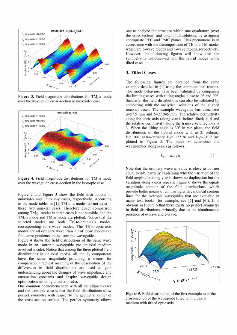
Figure 3. Field magnitude distributions for TMy31 mode over the waveguide cross-section in uniaxial-y case.
Figure 4. Field magnitude distributions for TMz31 mode over the waveguide cross-section in the isotropic case.
Figure 2 and Figure 3 show the field distributions in uniaxial-x and uniaxial-y cases, respectively. According to the mode tables in [1], TM-to-z modes do not exist in these two uniaxial cases. Therefore direct comparison among TMz31 modes in three cases is not possible, and the TMx31 mode and TMy31 mode are plotted. Notice that the selected modes are both TM-to-optic-axis modes, corresponding to e-wave modes. The TE-to-optic-axis modes are all ordinary wave, thus all of those modes can find correspondence in the isotropic waveguides. Figure 4 shows the field distributions of the same wave mode in an isotropic waveguide (no uniaxial medium involved inside). Notice that among the three plotted field distributions in uniaxial media, all the Ez components have the same magnitude providing a means for comparison. Practical meaning of the observation of the differences in field distributions are used to gain understanding about the changes of wave impedance and attenuation constants and inspire waveguide design optimization utilizing uniaxial media. One common phenomena seen with all the aligned cases and the isotropic case is that the field distributions show perfect symmetry with respect to the geometric center of the cross-section surface. The perfect symmetry allows
one to analyze the structure within one quadrature (over the cross-section) and obtain full solutions by assigning appropriate PEC and PMC planes. This phenomena is in accordance with the decomposition of TE and TM modes which are o-wave modes and e-wave modes, respectively. However, the following figures will show that the symmetry is not observed with the hybrid modes in the tilted cases. 3. Tilted Cases The following figures are obtained from the same example detailed in [1] using the computational routine. The mode behaviors have been validated by comparing the limiting cases with tilting angles close to 0° and 90°. Similarly, the field distributions can also be validated by comparing with the analytical solutions of the aligned uniaxial cases. The example waveguide has dimension a=57.5 mm and b=27.945 mm. The relative permittivity along the optic axis (along z-axis before tilted) is 4 and the relative permittivity along the transverse directions is 3. When the tilting angle is 30° in y-z plane, the field distributions of the hybrid mode with m=2, ordinary ky=±106, extra-ordinary kyp= 122.76 and kyn=-210.5 are plotted in Figure 5. The index m determines the wavenumber along x-axis as follows.
= / (1)
Note that the ordinary wave ky value is close to but not equal to π/b, partially explaining why the variation of the field amplitude along y-axis shows no duplication but the variation along x-axis repeats. Figure 6 shows the equal-magnitude contour of the field distributions, which provide better means of comparing with canonical contour lines for the isotropic waveguides that are available in many text books (for example, see [5] and [6]). It is obvious in Figure 6 that there exists no perfect symmetry in field distributions, primarily due to the simultaneous presence of o-wave and e-wave.
Figure 5. Field distribution of the first example over the cross-section of the waveguide filled with uniaxial medium with titlted optic axis.
0
0.02
0.04
0.06
0.08
0.1 0
0.01
0.02
0.03
0.04
0.05
0
2
4
Y (m) --
--→
Uniaxial-Y (εt=2, ε
y=4.5)
X (m) ----→
Am
plitu
de ⏐
E⏐2 (
V/m
)2
Ex amplitude =0.4082
Ey amplitude =1.9052
Ez amplitude =1.0000
0
0.02
0.04
0.06
0.08
0.1 0
0.01
0.02
0.03
0.04
0.05
0
1
2
Y (m) --
--→
Isotropic (εr=2)
X (m) ----→
Am
plitu
de ⏐
E⏐2 (
V/m
)2
Ex amplitude =1.0059
Ey amplitude =0.6706
Ez amplitude =1.0000
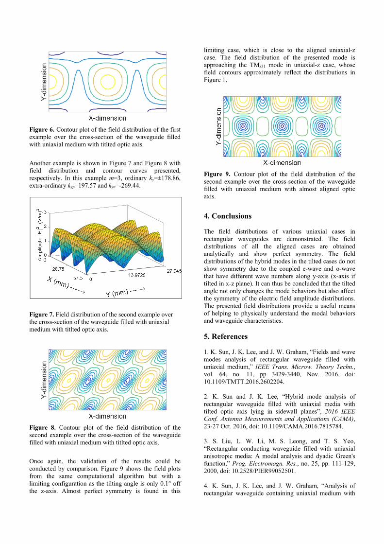
Figure 6. Contour plot of the field distribution of the first example over the cross-section of the waveguide filled with uniaxial medium with titlted optic axis.
Another example is shown in Figure 7 and Figure 8 with field distribution and contour curves presented, respectively. In this example m=3, ordinary ky=±178.86, extra-ordinary kyp=197.57 and kyn=-269.44.
Figure 7. Field distribution of the second example over the cross-section of the waveguide filled with uniaxial medium with titlted optic axis.
Figure 8. Contour plot of the field distribution of the second example over the cross-section of the waveguide filled with uniaxial medium with titlted optic axis.
Once again, the validation of the results could be conducted by comparison. Figure 9 shows the field plots from the same computational algorithm but with a limiting configuration as the tilting angle is only 0.1° off the z-axis. Almost perfect symmetry is found in this
limiting case, which is close to the aligned uniaxial-z case. The field distribution of the presented mode is approaching the TMz31 mode in uniaxial-z case, whose field contours approximately reflect the distributions in Figure 1.
Figure 9. Contour plot of the field distribution of the second example over the cross-section of the waveguide filled with uniaxial medium with almost aligned optic axis.
4. Conclusions The field distributions of various uniaxial cases in rectangular waveguides are demonstrated. The field distributions of all the aligned cases are obtained analytically and show perfect symmetry. The field distributions of the hybrid modes in the tilted cases do not show symmetry due to the coupled e-wave and o-wave that have different wave numbers along y-axis (x-axis if tilted in x-z plane). It can thus be concluded that the tilted angle not only changes the mode behaviors but also affect the symmetry of the electric field amplitude distributions. The presented field distributions provide a useful means of helping to physically understand the modal behaviors and waveguide characteristics. 5. References 1. K. Sun, J. K. Lee, and J. W. Graham, “Fields and wave modes analysis of rectangular waveguide filled with uniaxial medium,” IEEE Trans. Microw. Theory Techn., vol. 64, no. 11, pp 3429-3440, Nov. 2016, doi: 10.1109/TMTT.2016.2602204. 2. K. Sun and J. K. Lee, “Hybrid mode analysis of rectangular waveguide filled with uniaxial media with tilted optic axis lying in sidewall planes”, 2016 IEEE Conf. Antenna Measurements and Applications (CAMA), 23-27 Oct. 2016, doi: 10.1109/CAMA.2016.7815784. 3. S. Liu, L. W. Li, M. S. Leong, and T. S. Yeo, “Rectangular conducting waveguide filled with uniaxial anisotropic media: A modal analysis and dyadic Green's function,” Prog. Electromagn. Res., no. 25, pp. 111-129, 2000, doi: 10.2528/PIER99052501. 4. K. Sun, J. K. Lee, and J. W. Graham, “Analysis of rectangular waveguide containing uniaxial medium with
Y-d
imen
sion
Y-d
imen
sion

aligned optic axis,” IEEE Int. Symp. on Antennas and Propagat., Memphis, TN, pp.1564-1565, July 2014., doi: 10.1109/APS.2014.6905108. 5. R. F. Harrington, Time-Harmonic Electromagnetic Fields. New York: McGraw-Hill, 1961. 6. J. A. Kong, Electromagnetic Wave Theory. Cambridge, MA: EMW Publishing, 2008.