Embed Size (px)
Citation preview
8(2011) 351 – 372
The natural frequencies of composite Profiled Steel Sheet DryBoard with Concrete infill (PSSDBC) system
Abstract
This paper aims to measure natural frequencies of Profiled
Steel Sheet Dry Board (PSSDB) with Concrete infill (PSS-
DBC) system. For this purpose, experimental tests by es-
timation of Frequency Response Function (FRF) and a nu-
merical method by development of Finite Element Model
(FEM) are used. The connection stiffness between Peva45
as Profiled Steel Sheet (PSS) and different concrete grades
of 25 (C25), 30 (C30), and 35 (C35) are measured by push-
out tests to be used in the FEM. The effect of presence of
concrete in the PSSDB system on the natural frequencies
such as Fundamental Natural Frequency (FNF) of the sys-
tem is investigated. The variability in the FNF of the studied
system under different parameters such as concrete grades,
thicknesses of PSS and Dry Board (DB), and boundary con-
ditions is determined. In a wide numerical study, the FNF
of the PSSDBC system with practical dimensions is revealed
for different lengths, widths, and boundary conditions. The
results help designer predict serviceability and design criteria
of the studied panels.
Keywords
natural frequency, profiled steel sheet dry board, frequency
response function, modal analysis, push-out test, low and
high frequency floors, human comfort.
Farhad Abbas Gandomkar∗,Wan Hamidon Wan Badaruz-zaman and Siti Aminah Osman
Department of Civil & Structural Engineering,
Universiti Kebangsaan Malaysia, 43600 UKM
Bangi, Selangor Darul Ehsan – Malaysia
Received 03 Feb 2011;In revised form 06 Aug 2011
∗ Author email:[email protected]
1 INTRODUCTION
According to Wright and Evans [51], using profiled steel sheeting in composite slabs dominated
floor constructions during the eighties. They performed some tests on several types of sheeting
and carried out researches on the behavior of the sheeting under the wet concrete loading
during the construction phase and the slab performance under service loading after hardening
of the concrete. The results showed the possibility of using sheeting alone as a flooring system.
The wearing surface was provided by attachment of boarding to the sheeting which increased
the strength and stiffness of the system [51]. Then, a new composite component was presented
which is known as PSSDB system [52] with many advantages [48]. The PSSDB system is a
Latin American Journal of Solids and Structures 8(2011) 351 – 372
352 F.A. Gandomkar et al / The natural frequencies of composite PSSDBC system
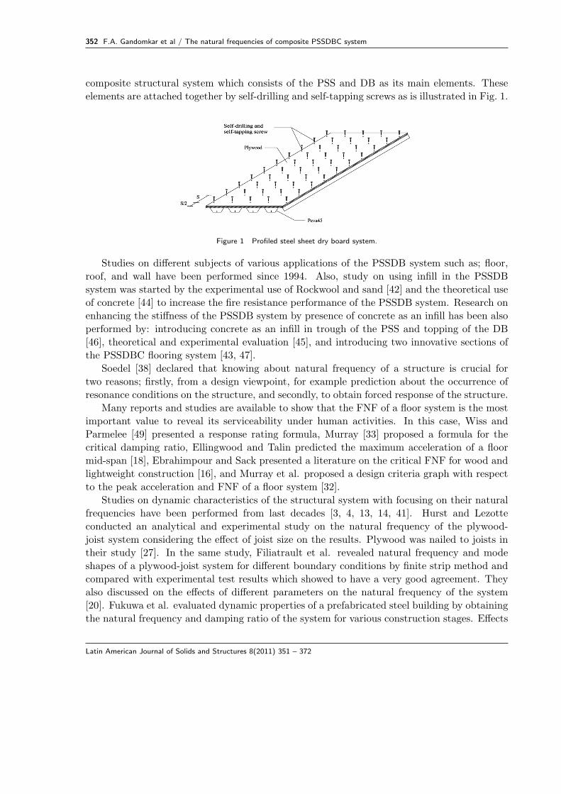
composite structural system which consists of the PSS and DB as its main elements. These
elements are attached together by self-drilling and self-tapping screws as is illustrated in Fig. 1.
Figure 1 Profiled steel sheet dry board system.
Studies on different subjects of various applications of the PSSDB system such as; floor,
roof, and wall have been performed since 1994. Also, study on using infill in the PSSDB
system was started by the experimental use of Rockwool and sand [42] and the theoretical use
of concrete [44] to increase the fire resistance performance of the PSSDB system. Research on
enhancing the stiffness of the PSSDB system by presence of concrete as an infill has been also
performed by: introducing concrete as an infill in trough of the PSS and topping of the DB
[46], theoretical and experimental evaluation [45], and introducing two innovative sections of
the PSSDBC flooring system [43, 47].
Soedel [38] declared that knowing about natural frequency of a structure is crucial for
two reasons; firstly, from a design viewpoint, for example prediction about the occurrence of
resonance conditions on the structure, and secondly, to obtain forced response of the structure.
Many reports and studies are available to show that the FNF of a floor system is the most
important value to reveal its serviceability under human activities. In this case, Wiss and
Parmelee [49] presented a response rating formula, Murray [33] proposed a formula for the
critical damping ratio, Ellingwood and Talin predicted the maximum acceleration of a floor
mid-span [18], Ebrahimpour and Sack presented a literature on the critical FNF for wood and
lightweight construction [16], and Murray et al. proposed a design criteria graph with respect
to the peak acceleration and FNF of a floor system [32].
Studies on dynamic characteristics of the structural system with focusing on their natural
frequencies have been performed from last decades [3, 4, 13, 14, 41]. Hurst and Lezotte
conducted an analytical and experimental study on the natural frequency of the plywood-
joist system considering the effect of joist size on the results. Plywood was nailed to joists in
their study [27]. In the same study, Filiatrault et al. revealed natural frequency and mode
shapes of a plywood-joist system for different boundary conditions by finite strip method and
compared with experimental test results which showed to have a very good agreement. They
also discussed on the effects of different parameters on the natural frequency of the system
[20]. Fukuwa et al. evaluated dynamic properties of a prefabricated steel building by obtaining
the natural frequency and damping ratio of the system for various construction stages. Effects
Latin American Journal of Solids and Structures 8(2011) 351 – 372
F.A. Gandomkar et al / The natural frequencies of composite PSSDBC system 353
of non-structural members on the results were investigated in their study [21]. El-Dardiry et
al. determined the natural frequency of a long-span flat concrete floor by using a suitable
FEM and an experimental heel-drop test. They considered several FEMs and refined them
by comparing their results with experimental test results, and then the most suitable FEM
was presented [17]. Ferreira and Fasshauer performed a free vibration study on a composite
plate by an innovative numerical method. Results of different thickness-to-length ratios were
determined and discussed in their study [19]. Xing and Liu derived successfully the natural
modes of a rectangular orthotropic plate by exact solution of mathematical statements for
three different boundary conditions [53]. Ju et al. developed a new composite floor system
and measured the natural frequencies and damping ratios of the system by experimental tests
for three different construction steps; steel erection stage, concrete casting stage, and finishing
stage. They compared the results with international codes to evaluate the serviceability of the
proposed floor system and obtained good vibration characteristics [28].
Study on the natural frequency of the PSSDB system is limited to an experimental study
done by Wright et al. [52] to identify the FNF of the system with considering PMF100 as the
PSS and chipboard as the DB. It was reported that since the PSSDB system is slender and
flexible in nature, the natural frequency of the system may be low and is perceivable by users.
In the case of serviceability of floor, it has been also stated that floor with the FNF lower than
approximately 7 Hz is considered to be uncomfortable to users [52]. Moreover, Gandomkar
et al. studied experimentally and numerically the natural frequencies of the PSSDB system
considering the effect of different parameters on the FNF of the studied system [23].
In accordance with Middleton and Brownjohn [31], there is little energy in the higher
harmonics after four harmonics of a walking force (approximately 10 Hz). A floor is High
Frequency Floor (HFF), if it has a FNF above 10 Hz. But, it is known as a Low Frequency
Floor (LFF) if it is dominated by resonance from the first four harmonics of a walking force.
Ljunggren et al. [29] stated that some researchers (Ohlsson, Wyatt & Dier, and Talja et al.)
suggested two different design criteria for floor; deflection criteria for HFF and an acceleration
limit for LFF. However, Murray et al. [32] recommended acceleration limit for LFF and HFF
and a minimum static stiffness of 1 kN/mm under concentrated load as an additional check
for HFF. Therefore, knowing about the FNF of a floor system can uncover: i) approach of
floor design and occurrence of resonance under human walking load by revealing the category
of the floor as LFF or HFF and ii) comfort level of a floor system.
Using non-structural systems such as partitions on a finished floor system and permanent
drywall partitions has an effect on the damping value of the floor system in comparison with
a bare floor [15]. Therefore, knowing about damping ratio of a bare floor system can help
designers select almost real damping ratio in the dynamic analysis of the system.
This paper by consideration of four goals attempts to present an investigation on the natural
frequencies of the PSSSBC system under different conditions. The first one is to identify the
natural frequencies and damping ratios of the PSSDBC system by experimental study; the
results will be also used to verify FEM. Secondly, is to develop FEM in order to obtain the
natural frequencies of the PSSDBC system. Thirdly, is to experimentally identify connection
Latin American Journal of Solids and Structures 8(2011) 351 – 372

354 F.A. Gandomkar et al / The natural frequencies of composite PSSDBC system
stiffness between Peva45 and different grades of concrete (25, 30, and 35) to show the effect
of concrete grade on the FNF of the PSSDBC system. Fourthly, is to determine the effect
of various selected parameters on the FNF through verified FEMs. The FNFs of panels with
practical dimensions are investigated for different boundary conditions through development
of fifteen FEMs. These developed panels when applied as a flooring system are also categorized
as LFF or HFF to reveal the occurrence of resonance under human walking load and design
criteria, and also whether they are comfortable or not for human occupant.
2 EXPERIMENTAL DETAILS
As stated, one of the objectives of this paper is to experimentally identify the natural fre-
quencies and damping ratios of the PSSDBC system. For this purpose, three specimens were
prepared as illustrated in Fig. 2. As mentioned before, Gandomkar et al. [23] studied the
natural frequencies of the PSSDB system without concrete infill selecting 0.8 mm Peva45 thick
as the PSS, 18 mm plywood thick as the DB, and DS-FH 432 self-drilling and self-tapping
screws with 200 mm screw spacing. In this study, the PSSDBC sample was also prepared
with similar materials as the PSSDB sample in Ref. [23] adding grade 30 concrete as an infill
material in trough of Peva45. The tests on the specimens were carried out 28 days after their
preparation in the laboratory. The length and width of all specimens have been considered as
2400 mm and 795 mm, respectively.
Figure 2 The PSSDBC system during the test.
Natural frequencies of the samples were measured by estimation of their FRFs. Excitation
and response signals of the studied systems were recorded and measured in order to obtain this
purpose. Bruel & Kjaer portable and multi-channel PULSE analyzer type 3560D, ENDEVCO
accelerometer type 751-100, and impact hammer type 2302-10 were used as the measuring
devices and also Bruel & Kjaer Pulse LabShop was the measurement software. Damping
ratios of the systems were also outcomes of the tests.
3 STRUCTURAL MODEL
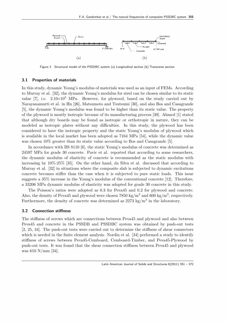
The structural model of the sample is shown in Fig. 3. The characteristics of the studied
system are presented in the following sections.
Latin American Journal of Solids and Structures 8(2011) 351 – 372
F.A. Gandomkar et al / The natural frequencies of composite PSSDBC system 355
(a) (b)
Figure 3 Structural model of the PSSDBC system (a) Longitudinal section (b) Transverse section.
3.1 Properties of materials
In this study, dynamic Young’s modulus of materials was used as an input of FEMs. According
to Murray et al. [32], the dynamic Young’s modulus for steel can be chosen similar to its static
value [7], i.e. 2.10×10⁵ MPa. However, for plywood, based on the study carried out by
Narayanamurti et al. in Hu [26], Matsumoto and Tsutsumi [30], and also Bos and Casagrande
[5], the dynamic Young’s modulus was found to be higher than its static value. The property
of the plywood is mostly isotropic because of its manufacturing process [39]. Ahmed [1] stated
that although dry boards may be found as isotropic or orthotropic in nature, they can be
modeled as isotropic plates without any difficulties. In this study, the plywood has been
considered to have the isotropic property and the static Young’s modulus of plywood which
is available in the local market has been adopted as 7164 MPa [54], while the dynamic value
was chosen 10% greater than its static value according to Bos and Casagrande [5].
In accordance with BS 8110 [6], the static Young’s modulus of concrete was determined as
24597 MPa for grade 30 concrete. Pavic et al. reported that according to some researchers,
the dynamic modulus of elasticity of concrete is recommended as the static modulus with
increasing by 10%-25% [35]. On the other hand, da Silva et al. discussed that according to
Murray et al. [32] in situations where the composite slab is subjected to dynamic excitations
concrete becomes stiffer than the case when it is subjected to pure static loads. This issue
suggests a 35% increase in the Young’s modulus of the conventional concrete [12]. Therefore,
a 33206 MPa dynamic modulus of elasticity was adopted for grade 30 concrete in this study.
The Poisson’s ratios were adopted as 0.3 for Peva45 and 0.2 for plywood and concrete.
Also, the density of Peva45 and plywood were chosen 7850 kg/m3 and 600 kg/m3, respectively.
Furthermore, the density of concrete was determined as 2273 kg/m3 in the laboratory.
3.2 Connection stiffness
The stiffness of screws which are connections between Peva45 and plywood and also between
Peva45 and concrete in the PSSDB and PSSDBC system was obtained by push-out tests
[2, 25, 34]. The push-out tests were carried out to determine the stiffness of shear connectors
which is needed in the finite element analysis. Nordin et al. [34] performed a study to identify
stiffness of screws between Peva45-Cemboard, Cemboard-Timber, and Peva45-Plywood by
push-out tests. It was found that the shear connection stiffness between Peva45 and plywood
was 610 N/mm [34].
Latin American Journal of Solids and Structures 8(2011) 351 – 372
356 F.A. Gandomkar et al / The natural frequencies of composite PSSDBC system
The connection between Peva45 and concrete as an infill in trough of Peva45 is also a
partial interaction problem. Harsoyo found the connection stiffness between Peva45 and C30
by push-out tests where Cemboard and wood were selected as covering [25].
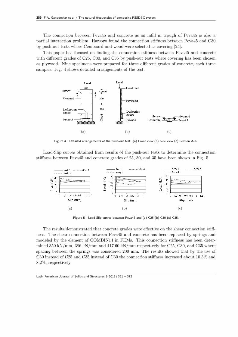
This paper has focused on finding the connection stiffness between Peva45 and concrete
with different grades of C25, C30, and C35 by push-out tests where covering has been chosen
as plywood. Nine specimens were prepared for three different grades of concrete, each three
samples. Fig. 4 shows detailed arrangements of the test.
(a) (b) (c)
Figure 4 Detailed arrangements of the push-out test: (a) Front view (b) Side view (c) Section A-A.
Load-Slip curves obtained from results of the push-out tests to determine the connection
stiffness between Peva45 and concrete grades of 25, 30, and 35 have been shown in Fig. 5.
(a) (b) (c)
Figure 5 Load-Slip curves between Peva45 and (a) C25 (b) C30 (c) C35.
The results demonstrated that concrete grades were effective on the shear connection stiff-
ness. The shear connection between Peva45 and concrete has been replaced by springs and
modeled by the element of COMBIN14 in FEMs. This connection stiffness has been deter-
mined 350 kN/mm, 386 kN/mm and 417.60 kN/mm respectively for C25, C30, and C35 where
spacing between the springs was considered 200 mm. The results showed that by the use of
C30 instead of C25 and C35 instead of C30 the connection stiffness increased about 10.3% and
8.2%, respectively.
Latin American Journal of Solids and Structures 8(2011) 351 – 372
F.A. Gandomkar et al / The natural frequencies of composite PSSDBC system 357
4 COMPUTATIONAL MODEL
In this study, the natural frequencies of the PSSDBC system were also determined through
development of a finite element model to meet the second goal by implementation of the
ANSYS program [40]. The developed finite element model was analyzed by “Modal analysis”.
Two methods were selected to evaluate natural frequencies of the system. The first method was
eigenvalue solver of “Block Lanczos” to obtain undamped natural frequencies of the studied
system which is available for eigenvalue problems in large symmetric models [40]. Shifted Block
Lanczos algorithm is the theoretical base of this eigensolver whilst more information about
this algorithm can be found in Ref. [24]. A variation of the classical Lanczos algorithm is the
Block Lanczos algorithm where the Lanczos recursion is conducted with a block of vectors.
Further theoretical points on the classical Lanczos algorithm are existed in Ref. [11] and in
the study performed by Rajakumar and Rogers (1991) [40]. By the use of a check method,
this procedure is applicable to find eigenfrequencies of a system without missing any modes.
This solver carries out rightly when the model consists of shell elements or a combination of
shell and solid elements. The second one was “QR damped” [40] method to evaluate damped
natural frequencies (eigenvalues) and corresponding mode shapes (eigenvectors) of the studied
system. This procedure utilizes QR algorithm to compute the eigenvalues of the system whilst
further information about the algorithm can be also found in Ref. [37]. Moreover, according to
ANSYS [40], the eigenvectors are extracted by using the inverse iteration method presented by
Wilkinson and Reinsch (1971). The “QR damped” method presents good results for structural
systems with light damping. Any types of damping such as; proportional or non-proportional
symmetric damping or non-symmetrical gyroscopic damping matrix (see manual of Ref. [40]
for more information) can be used in this method. The “QR damped” eigensolver performs
best in larger models. If there is nonsymmetrical stiffness in the model, this approach can also
support it.
In the PSSDBC computational model, the PSS and DB were made of SHELL281 element
as a suitable element for analyzing thin to moderately-thick shell structures [40]. In addition,
the self-drilling and self-tapping screws were represented by COMBIN14 element as connection
between Peva45 and plywood and also concrete and Peva45. In this study, structural method of
connection between concrete and Peva45 was used as a method which presented in Ref. [25].
Moreover, SOLID65 element was assumed for modeling the concrete in the computational
model.
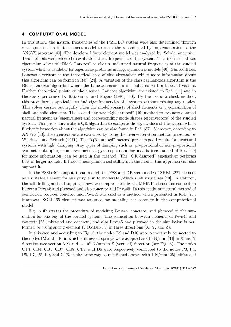
Fig. 6 illustrates the procedure of modeling Peva45, concrete, and plywood in the sim-
ulation for one bay of the studied system. The connection between elements of Peva45 and
concrete [25], plywood and concrete, and also Peva45 and plywood in the simulation is per-
formed by using spring element (COMBIN14) in three directions (X, Y, and Z).
In this case and according to Fig. 6, the nodes D2 and D10 were respectively connected to
the nodes P2 and P10 in which stiffness of springs were adopted as 610 N/mm [34] in X and Y
direction (see section 3.2) and as 105 N/mm in Z (vertical) direction (see Fig. 6). The nodes
CT3, CB4, CB5, CB7, CB8, CT9, and D6 were respectively connected to the nodes P3, P4,
P5, P7, P8, P9, and CT6, in the same way as mentioned above, with 1 N/mm [25] stiffness of
Latin American Journal of Solids and Structures 8(2011) 351 – 372
358 F.A. Gandomkar et al / The natural frequencies of composite PSSDBC system
(a)
(b)
Figure 6 (a) One bay PSSDBC structural system (b) Situation of nodes in elements of one bay PSSDBCsystem.
springs for all directions (X, Y, and Z). When C30 was used as concrete infill, the node CM6
was connected to the node P6 with 386000 N/mm stiffness of springs in X and Y direction
(see section 3.2) and 106 N/mm stiffness of springs in Z direction.
5 OBSERVATION OF RESULTS AND COMPARISON
Results of this section are presented in two parts; experimental tests and finite element simu-
lations. Then, the experimental and finite element results are compared to show the accuracy
of the FEM of the PSSDBC system.
This section has also concentrated on revealing the effect of concrete on the natural fre-
quencies of the PSSDB system by comparing the experimental results of the current study
with results of Ref. [23].
5.1 Experimental results
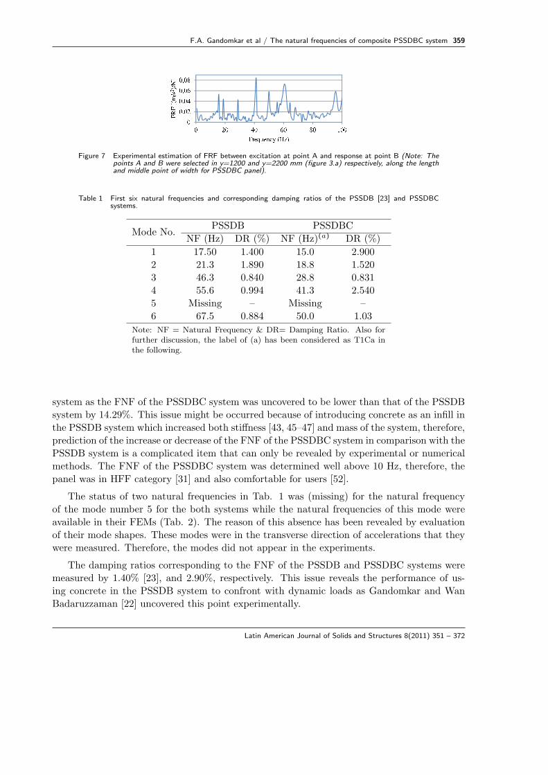
The FRF of the studied system is shown in Fig. 7. The first six natural frequencies of the
system and damping ratios corresponding to the natural frequencies are summarized in Tab. 1.
Also, the natural frequencies and their corresponding damping ratios of the PSSDB system
are presented in Tab. 1 [23].
All six natural frequencies of the PSSDBC system were measured less than the PSSDB
Latin American Journal of Solids and Structures 8(2011) 351 – 372
F.A. Gandomkar et al / The natural frequencies of composite PSSDBC system 359
Figure 7 Experimental estimation of FRF between excitation at point A and response at point B (Note: Thepoints A and B were selected in y=1200 and y=2200 mm (figure 3.a) respectively, along the lengthand middle point of width for PSSDBC panel).
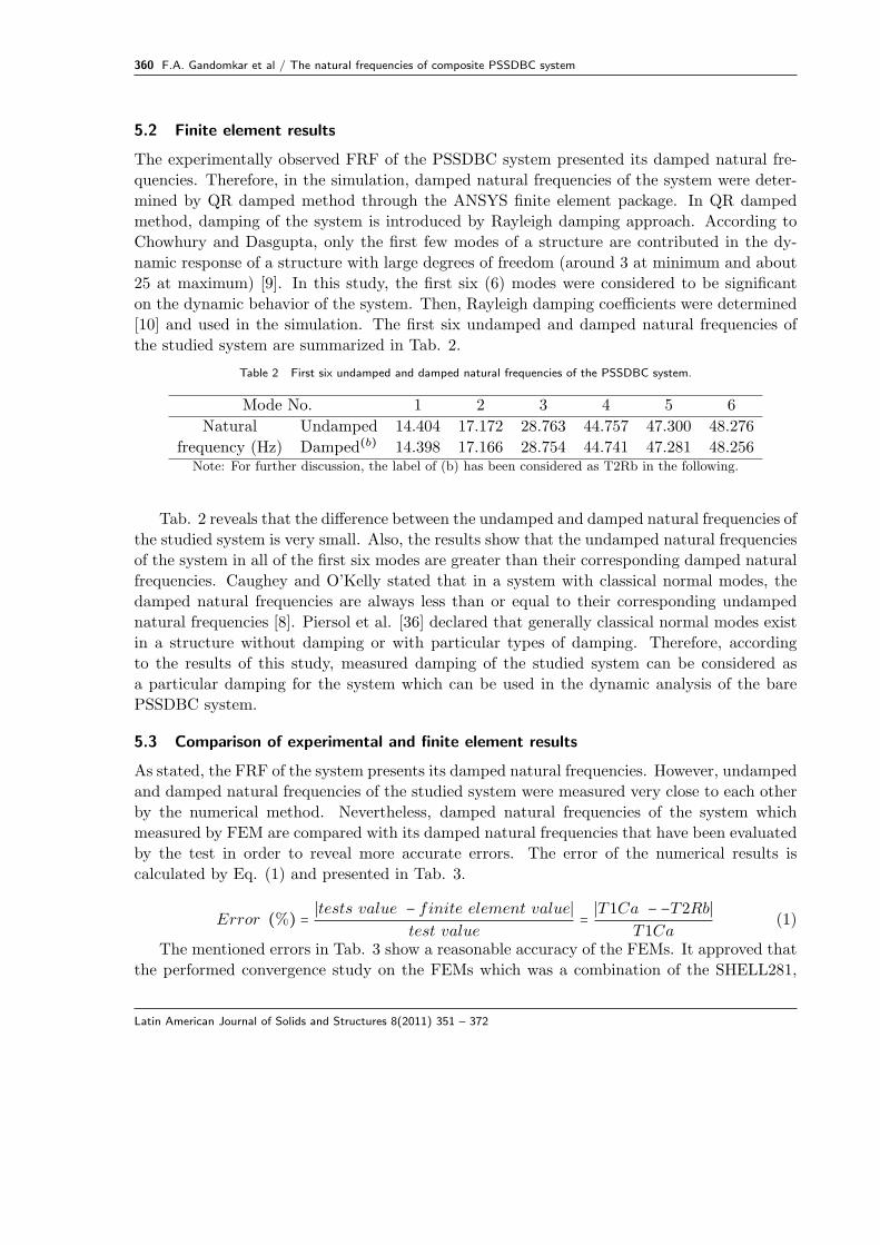
Table 1 First six natural frequencies and corresponding damping ratios of the PSSDB [23] and PSSDBCsystems.
Mode No.PSSDB PSSDBC
NF (Hz) DR (%) NF (Hz)(a) DR (%)
1 17.50 1.400 15.0 2.900
2 21.3 1.890 18.8 1.520
3 46.3 0.840 28.8 0.831
4 55.6 0.994 41.3 2.540
5 Missing – Missing –
6 67.5 0.884 50.0 1.03
Note: NF = Natural Frequency & DR= Damping Ratio. Also forfurther discussion, the label of (a) has been considered as T1Ca inthe following.
system as the FNF of the PSSDBC system was uncovered to be lower than that of the PSSDB
system by 14.29%. This issue might be occurred because of introducing concrete as an infill in
the PSSDB system which increased both stiffness [43, 45–47] and mass of the system, therefore,
prediction of the increase or decrease of the FNF of the PSSDBC system in comparison with the
PSSDB system is a complicated item that can only be revealed by experimental or numerical
methods. The FNF of the PSSDBC system was determined well above 10 Hz, therefore, the
panel was in HFF category [31] and also comfortable for users [52].
The status of two natural frequencies in Tab. 1 was (missing) for the natural frequency
of the mode number 5 for the both systems while the natural frequencies of this mode were
available in their FEMs (Tab. 2). The reason of this absence has been revealed by evaluation
of their mode shapes. These modes were in the transverse direction of accelerations that they
were measured. Therefore, the modes did not appear in the experiments.
The damping ratios corresponding to the FNF of the PSSDB and PSSDBC systems were
measured by 1.40% [23], and 2.90%, respectively. This issue reveals the performance of us-
ing concrete in the PSSDB system to confront with dynamic loads as Gandomkar and Wan
Badaruzzaman [22] uncovered this point experimentally.
Latin American Journal of Solids and Structures 8(2011) 351 – 372
360 F.A. Gandomkar et al / The natural frequencies of composite PSSDBC system
5.2 Finite element results
The experimentally observed FRF of the PSSDBC system presented its damped natural fre-
quencies. Therefore, in the simulation, damped natural frequencies of the system were deter-
mined by QR damped method through the ANSYS finite element package. In QR damped
method, damping of the system is introduced by Rayleigh damping approach. According to
Chowhury and Dasgupta, only the first few modes of a structure are contributed in the dy-
namic response of a structure with large degrees of freedom (around 3 at minimum and about
25 at maximum) [9]. In this study, the first six (6) modes were considered to be significant
on the dynamic behavior of the system. Then, Rayleigh damping coefficients were determined
[10] and used in the simulation. The first six undamped and damped natural frequencies of
the studied system are summarized in Tab. 2.
Table 2 First six undamped and damped natural frequencies of the PSSDBC system.
Mode No. 1 2 3 4 5 6
Natural Undamped 14.404 17.172 28.763 44.757 47.300 48.276
frequency (Hz) Damped(b) 14.398 17.166 28.754 44.741 47.281 48.256Note: For further discussion, the label of (b) has been considered as T2Rb in the following.
Tab. 2 reveals that the difference between the undamped and damped natural frequencies of
the studied system is very small. Also, the results show that the undamped natural frequencies
of the system in all of the first six modes are greater than their corresponding damped natural
frequencies. Caughey and O’Kelly stated that in a system with classical normal modes, the
damped natural frequencies are always less than or equal to their corresponding undamped
natural frequencies [8]. Piersol et al. [36] declared that generally classical normal modes exist
in a structure without damping or with particular types of damping. Therefore, according
to the results of this study, measured damping of the studied system can be considered as
a particular damping for the system which can be used in the dynamic analysis of the bare
PSSDBC system.
5.3 Comparison of experimental and finite element results
As stated, the FRF of the system presents its damped natural frequencies. However, undamped
and damped natural frequencies of the studied system were measured very close to each other
by the numerical method. Nevertheless, damped natural frequencies of the system which
measured by FEM are compared with its damped natural frequencies that have been evaluated
by the test in order to reveal more accurate errors. The error of the numerical results is
calculated by Eq. (1) and presented in Tab. 3.
Error (%) = ∣tests value − finite element value∣test value
= ∣T1Ca − −T2Rb∣T1Ca
(1)
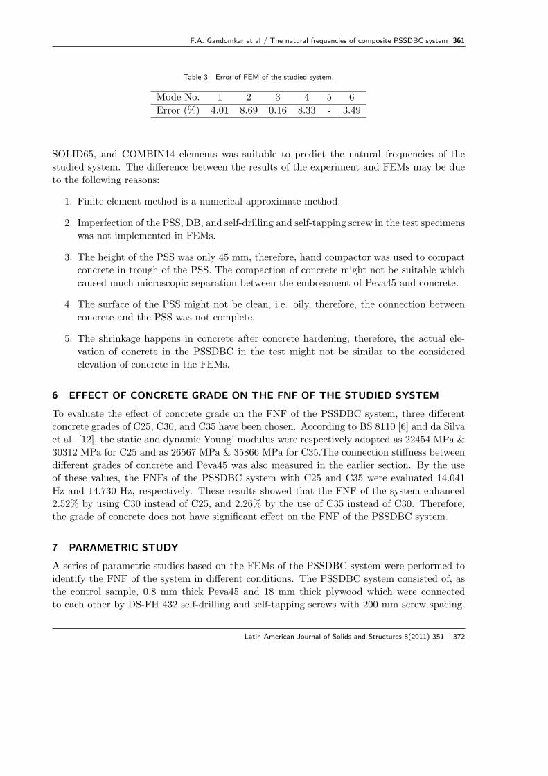
The mentioned errors in Tab. 3 show a reasonable accuracy of the FEMs. It approved that
the performed convergence study on the FEMs which was a combination of the SHELL281,
Latin American Journal of Solids and Structures 8(2011) 351 – 372
F.A. Gandomkar et al / The natural frequencies of composite PSSDBC system 361
Table 3 Error of FEM of the studied system.
Mode No. 1 2 3 4 5 6
Error (%) 4.01 8.69 0.16 8.33 - 3.49
SOLID65, and COMBIN14 elements was suitable to predict the natural frequencies of the
studied system. The difference between the results of the experiment and FEMs may be due
to the following reasons:
1. Finite element method is a numerical approximate method.
2. Imperfection of the PSS, DB, and self-drilling and self-tapping screw in the test specimens
was not implemented in FEMs.
3. The height of the PSS was only 45 mm, therefore, hand compactor was used to compact
concrete in trough of the PSS. The compaction of concrete might not be suitable which
caused much microscopic separation between the embossment of Peva45 and concrete.
4. The surface of the PSS might not be clean, i.e. oily, therefore, the connection between
concrete and the PSS was not complete.
5. The shrinkage happens in concrete after concrete hardening; therefore, the actual ele-
vation of concrete in the PSSDBC in the test might not be similar to the considered
elevation of concrete in the FEMs.
6 EFFECT OF CONCRETE GRADE ON THE FNF OF THE STUDIED SYSTEM
To evaluate the effect of concrete grade on the FNF of the PSSDBC system, three different
concrete grades of C25, C30, and C35 have been chosen. According to BS 8110 [6] and da Silva
et al. [12], the static and dynamic Young’ modulus were respectively adopted as 22454 MPa &
30312 MPa for C25 and as 26567 MPa & 35866 MPa for C35.The connection stiffness between
different grades of concrete and Peva45 was also measured in the earlier section. By the use
of these values, the FNFs of the PSSDBC system with C25 and C35 were evaluated 14.041
Hz and 14.730 Hz, respectively. These results showed that the FNF of the system enhanced
2.52% by using C30 instead of C25, and 2.26% by the use of C35 instead of C30. Therefore,
the grade of concrete does not have significant effect on the FNF of the PSSDBC system.
7 PARAMETRIC STUDY
A series of parametric studies based on the FEMs of the PSSDBC system were performed to
identify the FNF of the system in different conditions. The PSSDBC system consisted of, as
the control sample, 0.8 mm thick Peva45 and 18 mm thick plywood which were connected
to each other by DS-FH 432 self-drilling and self-tapping screws with 200 mm screw spacing.
Latin American Journal of Solids and Structures 8(2011) 351 – 372
362 F.A. Gandomkar et al / The natural frequencies of composite PSSDBC system
Also, concrete grade of C30 was selected as an infill material in trough of Peva45. The supports
of the samples have been chosen as pin supports at Y=0 and roller at Y=2400 mm (Fig. 3.a),
both in the bottom flange of the PSS. Dimensions of the studied panel were selected 2400 mm
as the length and 795 mm as the width. A series of studies were performed to uncover the FNF
of the PSSDBC panels with practical dimensions. Their categorization and comfortableness
were also revealed.
7.1 Effect of thickness of Peva45 and Plywood
The thickness of Peva45 was considered 0.8 mm and 1.0 mm and also the thickness of plywood
was adopted 9.252 mm, 12.7 mm, 18 mm, 23 mm, and 25 mm which are available in the local
market.
Effects of thickness of Peva45 and plywood on the FNF of the PSSDBC system are pre-
sented in Tab. 4. The results showed that increasing the thickness of Peva45 and plywood
respectively enhanced and decreased the FNF of the system. Therefore, this point revealed
that the effectiveness of the plywood mass is higher than its stiffness on the FNF of the sys-
tem. Also, the effectiveness of the Peva45 stiffness was shown to be higher than its mass. By
changing thickness of Peva45 from 0.8 mm to 1.0 mm and thickness of plywood from 9.252
mm to 25 mm it has been shown that the FNF of the system increased and decreased by an
average value of 3.11% and 3.94%, respectively. The maximum and minimum values of the
FNF of the PSSDBC system were identified as 15.199 Hz (for maximum thickness of Peva45
and minimum thickness of plywood) and 14.146 Hz (for maximum thickness of plywood and
minimum thickness of Peva45), respectively. Therefore, by changing the thickness of the main
elements, the FNF of the system increased only a maximum of 7.44%. The minimum value
of the FNF of the PSSDBC shows well above 10 Hz, therefore, the studied system was in the
category of HFF [31] and comfortable for occupants [52].
Table 4 Effect of thickness of Peva45 and plywood on the FNF of the system.
Peva45Plywood
t=9.252 mm t=12.7 mm t=18 mm t=23 mm t=25 mm
FNF (Hz)t=0.8 mm 14.727 14.549 14.404 14.182 14.146
t=1.0 mm 15.199 15.019 14.790 14.641 14.601
7.2 Effect of boundary conditions
Effect of different boundary conditions on the FNF of the PSSDBC system with changing
support conditions has been considered as three situations such as; effect of sliding and rotation
at the end supports perpendicular to the strong direction of the PSS (sliding parallel with Y
direction of the plan, Figure 8), effect of locating support under the top flange and web of the
PSS at two ends of the length, and effect of adding support parallel with the strong direction
of the PSS (parallel with Y direction of the plan, Figure 10).
Latin American Journal of Solids and Structures 8(2011) 351 – 372
F.A. Gandomkar et al / The natural frequencies of composite PSSDBC system 363
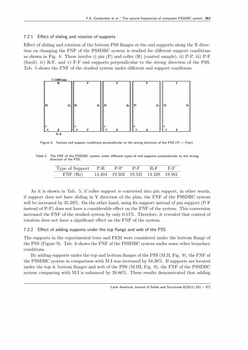
7.2.1 Effect of sliding and rotation of supports
Effect of sliding and rotation of the bottom PSS flanges at the end supports along the X direc-
tion on changing the FNF of the PSSDBC system is studied for different support conditions
as shown in Fig. 8. These involve i) pin (P) and roller (R) (control sample), ii) P-P, iii) P-F
(fixed), iv) R-F, and v) F-F end supports perpendicular to the strong direction of the PSS.
Tab. 5 shows the FNF of the studied system under different end support conditions.
Figure 8 Various end support conditions perpendicular to the strong direction of the PSS (Fr = Free).
Table 5 The FNF of the PSSDBC system under different types of end supports perpendicular to the strongdirection of the PSS.
Type of Support P-R P-P P-F R-F F-F
FNF (Hz) 14.404 19.502 19.531 14.428 19.561
As it is shown in Tab. 5, if roller support is converted into pin support, in other words,
if support does not have sliding in Y direction of the plan, the FNF of the PSSDBC system
will be increased by 35.39%. On the other hand, using fix support instead of pin support (P-F
instead of P-P) does not have a considerable effect on the FNF of the system. This conversion
increased the FNF of the studied system by only 0.15%. Therefore, it revealed that control of
rotation does not have a significant effect on the FNF of the system.
7.2.2 Effect of adding supports under the top flange and web of the PSS
The supports in the experimental tests and FEM were considered under the bottom flange of
the PSS (Figure 9). Tab. 6 shows the FNF of the PSSDBC system under some other boundary
conditions.
By adding supports under the top and bottom flanges of the PSS (M.II, Fig. 9), the FNF of
the PSSDBC system in comparison with M.I was increased by 34.38%. If supports are located
under the top & bottom flanges and web of the PSS (M.III, Fig. 9), the FNF of the PSSDBC
system comparing with M.I is enhanced by 39.86%. These results demonstrated that adding
Latin American Journal of Solids and Structures 8(2011) 351 – 372

364 F.A. Gandomkar et al / The natural frequencies of composite PSSDBC system
Table 6 Effect of adding supports under the top flange and web of the PSS on the FNF.
Model of
support
P-R support in
bottom flange (M.I)
P-R support under
bottom and top flanges
(M.II)
P-R support under
bottom and top flanges
and web of PSS (M.III)
FNF (Hz) 14.404 19.356 20.145
supports under the top flange of the PSS (M.II) had an apparent effect on the increase of the
FNF of the studied system. However, considering support under the web of the PSS (M.III) in
comparison with M.II improves the FNF of the PSSDBC system by only 5.48%. These results
help designers select shapes of supports under Peva45 to have greater values of FNF.
Figure 9 Illustration of supports under top & bottom flanges and web of the PSS.
7.2.3 Effect of adding support parallel to longitudinal side edges
The supports of the longitudinal side edges (support in X=0 and 795 mm, Fig. 3.b) for the
control sample were considered free (unconstrained). Different additional support conditions
which were investigated at the longitudinal side edges are illustrated in Fig. 10.
Figure 10 Different support conditions parallel to the strong direction of the PSS.
Tab. 7 summarizes the FNF of the PSSDBC system under various support conditions
which illustrated in Fig. 10.
Latin American Journal of Solids and Structures 8(2011) 351 – 372
F.A. Gandomkar et al / The natural frequencies of composite PSSDBC system 365
Table 7 Effect of adding supports parallel to the strong direction of the PSS on the FNF.
Model of support (i) (ii) (iii) (iv) (v) (vi)
FNF (Hz) 14.404 15.441 16.269 20.575 22.104 23.696
Tab. 7 reveals that considering roller and pin supports in Y direction in only one edge of
the panel increased the FNF of the system by 7.20% and 12.95%. It uncovered that if the
support is converted from roller into pin, in other words, if sliding of the support is controlled
in the wide side of the panel, the FNF of the system will be increased by 5.75% (12.95%-7.2%).
However, by restraining both longitudinal side edges as supports models of (iv), (v), and (vi),
the increase of FNF is much more pronounced, i.e. an increase of 42.84%, 53.46%, and 64.51%,
respectively. It is obvious from the above that if only three sides of the PSSDBC panel were
supported; restraining the sliding in the X direction at the longitudinal side edges would not
change much the FNF. When all four sides of the panels were supported instead of only three
it became much more significant.
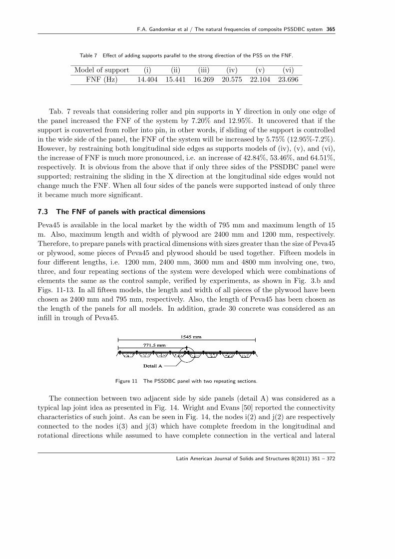
7.3 The FNF of panels with practical dimensions
Peva45 is available in the local market by the width of 795 mm and maximum length of 15
m. Also, maximum length and width of plywood are 2400 mm and 1200 mm, respectively.
Therefore, to prepare panels with practical dimensions with sizes greater than the size of Peva45
or plywood, some pieces of Peva45 and plywood should be used together. Fifteen models in
four different lengths, i.e. 1200 mm, 2400 mm, 3600 mm and 4800 mm involving one, two,
three, and four repeating sections of the system were developed which were combinations of
elements the same as the control sample, verified by experiments, as shown in Fig. 3.b and
Figs. 11-13. In all fifteen models, the length and width of all pieces of the plywood have been
chosen as 2400 mm and 795 mm, respectively. Also, the length of Peva45 has been chosen as
the length of the panels for all models. In addition, grade 30 concrete was considered as an
infill in trough of Peva45.
Figure 11 The PSSDBC panel with two repeating sections.
The connection between two adjacent side by side panels (detail A) was considered as a
typical lap joint idea as presented in Fig. 14. Wright and Evans [50] reported the connectivity
characteristics of such joint. As can be seen in Fig. 14, the nodes i(2) and j(2) are respectively
connected to the nodes i(3) and j(3) which have complete freedom in the longitudinal and
rotational directions while assumed to have complete connection in the vertical and lateral
Latin American Journal of Solids and Structures 8(2011) 351 – 372
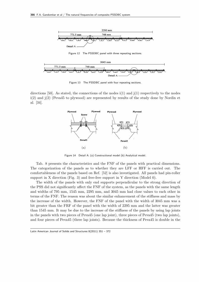
366 F.A. Gandomkar et al / The natural frequencies of composite PSSDBC system
Figure 12 The PSSDBC panel with three repeating sections.
Figure 13 The PSSDBC panel with four repeating sections.
directions [50]. As stated, the connections of the nodes i(1) and j(1) respectively to the nodes
i(2) and j(2) (Peva45 to plywood) are represented by results of the study done by Nordin et
al. [34].
(a) (b)
Figure 14 Detail A: (a) Constructional model (b) Analytical model.
Tab. 8 presents the characteristics and the FNF of the panels with practical dimensions.
The categorization of the panels as to whether they are LFF or HFF is carried out. The
comfortableness of the panels based on Ref. [52] is also investigated. All panels had pin-roller
support in X direction (Fig. 3) and free-free support in Y direction (Model 0).
The width of the panels with only end supports perpendicular to the strong direction of
the PSS did not significantly affect the FNF of the system, as the panels with the same length
and widths of 795 mm, 1545 mm, 2295 mm, and 3045 mm had close values to each other in
terms of the FNF. The reason was about the similar enhancement of the stiffness and mass by
the increase of the width. However, the FNF of the panel with the width of 3045 mm was a
bit greater than the FRF of the panel with the width of 2295 mm and the latter was greater
than 1545 mm. It may be due to the increase of the stiffness of the panels by using lap joints
in the panels with two pieces of Peva45 (one lap joint), three pieces of Peva45 (two lap joints),
and four pieces of Peva45 (three lap joints). Because the thickness of Peva45 is double in the
Latin American Journal of Solids and Structures 8(2011) 351 – 372
F.A. Gandomkar et al / The natural frequencies of composite PSSDBC system 367
Table 8 Characteristics, FNF, and evaluation of the developed PSSDBC models (Model 0).
Name of Length Width FNF Status of the studied system
panel (mm) (mm) (Hz) (b) (c)
1PP1LL 1200 795 47.672 HFF Ok
1PP2LL(a) 2400 795 14.404 HFF Ok
1PP3LL 3600 795 6.5513 LFF Failed
1PP4LL 4800 795 3.7009 LFF Failed
2PP1LL 1200 1545 50.995 HFF Ok
2PP2LL 2400 1545 14.359 HFF Ok
2PP3LL 3600 1545 6.4161 LFF Failed
2PP4LL 4800 1545 3.6072 LFF Failed
3PP1LL 1200 2295 52.202 HFF Ok
3PP2LL 2400 2295 14.373 HFF Ok
3PP3LL 3600 2295 6.4196 LFF Failed
3PP4LL 4800 2295 3.6466 LFF Failed
4PP1LL 1200 3045 52.520 HFF Ok
4PP2LL 2400 3045 14.462 HFF Ok
4PP3LL 3600 3045 6.4564 LFF Failed
4PP4LL 4800 3045 3.6478 LFF Failed
(a) Control sample(b) Categorization of system as LFF or HFF [31](c) Comfortableness of panels for occupants [52]
location of the lap joint, while, according to the lap joint idea the connection between two
pieces of Peva45 is not complete.
As it is obvious, the length of the system has a direct effect on its FNF. The results on the
studied panels showed that the FNF of the system with the length of greater than 3600 mm
was uncomfortable [52]; therefore, they will be in the category of LFF.
Comparing results of Ref. [23] and the current study, it was revealed that the presence of
concrete did not have a considerable effect on the decrease of the FNF of the PSSDB system
with the length of 1200 mm. However, this presence significantly affected the reduction of
the FNF of the PSSDB system with the lengths of 2400 mm, 3600 mm, and 4800mm, as in
practical panels i.e. 3PP3LL, 3PP4LL, 4PP3LL, and 4PP4LL the maximum decrease in the
FNF of the panels was 14.69%. However, this value was identified for grade 30 concrete and
it can be reduced a little by higher concrete grades.
Increase in the FNF of a floor system is required since the floor is needed to be away
from resonance under human walking load and to become comfortable for users. If panels are
supported at all sides, the FNF of the system will be increased. Depending on the control of
sliding in supports, roller or pin supports can be used in all sides. For this case, all panels with
the lengths of 3600 mm and 4800 mm were selected in order to increase their FNFs through
Latin American Journal of Solids and Structures 8(2011) 351 – 372
368 F.A. Gandomkar et al / The natural frequencies of composite PSSDBC system
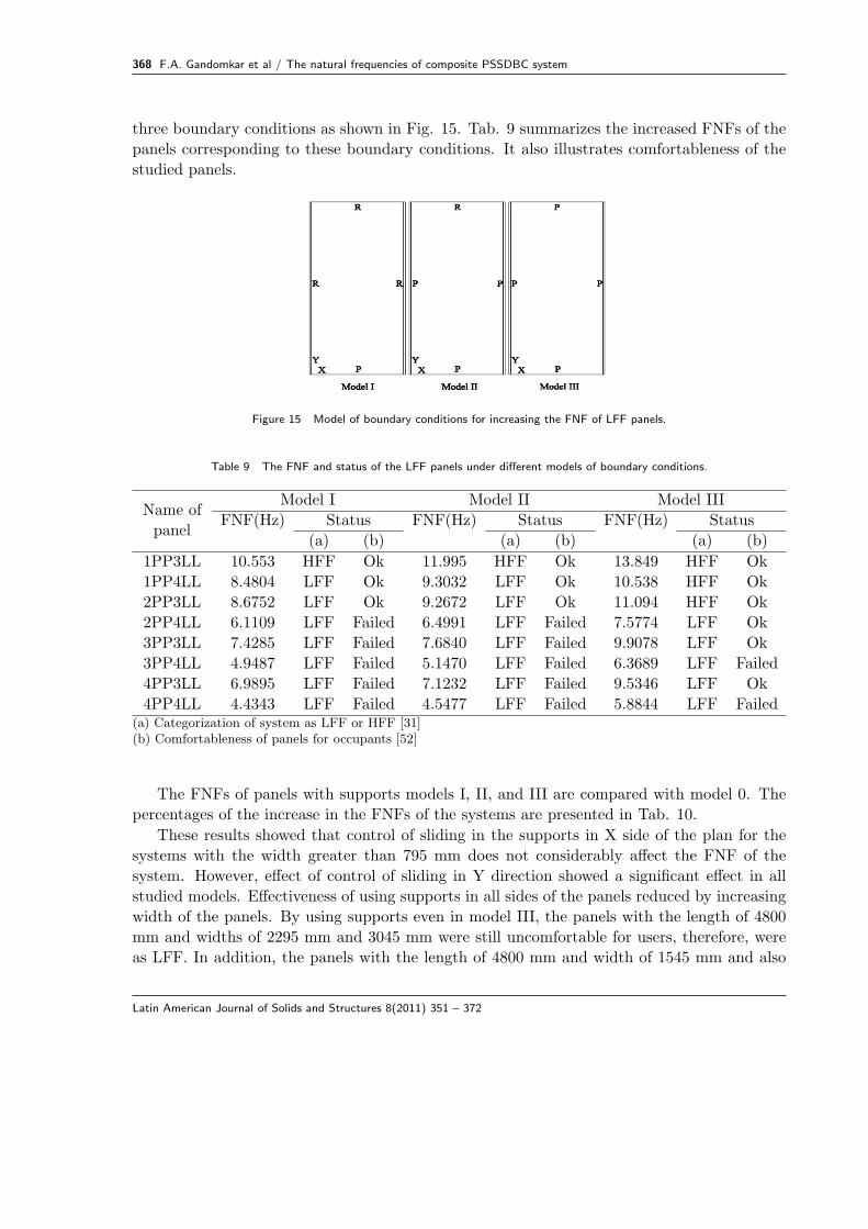
three boundary conditions as shown in Fig. 15. Tab. 9 summarizes the increased FNFs of the
panels corresponding to these boundary conditions. It also illustrates comfortableness of the
studied panels.
Figure 15 Model of boundary conditions for increasing the FNF of LFF panels.
Table 9 The FNF and status of the LFF panels under different models of boundary conditions.
Name of
panel
Model I Model II Model III
FNF(Hz) Status FNF(Hz) Status FNF(Hz) Status
(a) (b) (a) (b) (a) (b)
1PP3LL 10.553 HFF Ok 11.995 HFF Ok 13.849 HFF Ok
1PP4LL 8.4804 LFF Ok 9.3032 LFF Ok 10.538 HFF Ok
2PP3LL 8.6752 LFF Ok 9.2672 LFF Ok 11.094 HFF Ok
2PP4LL 6.1109 LFF Failed 6.4991 LFF Failed 7.5774 LFF Ok
3PP3LL 7.4285 LFF Failed 7.6840 LFF Failed 9.9078 LFF Ok
3PP4LL 4.9487 LFF Failed 5.1470 LFF Failed 6.3689 LFF Failed
4PP3LL 6.9895 LFF Failed 7.1232 LFF Failed 9.5346 LFF Ok
4PP4LL 4.4343 LFF Failed 4.5477 LFF Failed 5.8844 LFF Failed(a) Categorization of system as LFF or HFF [31](b) Comfortableness of panels for occupants [52]
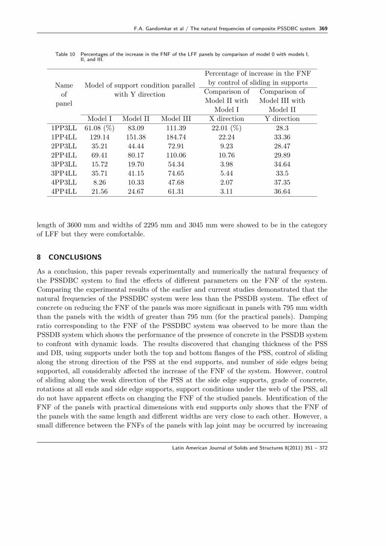
The FNFs of panels with supports models I, II, and III are compared with model 0. The
percentages of the increase in the FNFs of the systems are presented in Tab. 10.
These results showed that control of sliding in the supports in X side of the plan for the
systems with the width greater than 795 mm does not considerably affect the FNF of the
system. However, effect of control of sliding in Y direction showed a significant effect in all
studied models. Effectiveness of using supports in all sides of the panels reduced by increasing
width of the panels. By using supports even in model III, the panels with the length of 4800
mm and widths of 2295 mm and 3045 mm were still uncomfortable for users, therefore, were
as LFF. In addition, the panels with the length of 4800 mm and width of 1545 mm and also
Latin American Journal of Solids and Structures 8(2011) 351 – 372
F.A. Gandomkar et al / The natural frequencies of composite PSSDBC system 369
Table 10 Percentages of the increase in the FNF of the LFF panels by comparison of model 0 with models I,II, and III.
Name
of
panel
Model of support condition parallel
with Y direction
Percentage of increase in the FNF
by control of sliding in supports
Comparison of
Model II with
Model I
Comparison of
Model III with
Model II
Model I Model II Model III X direction Y direction
1PP3LL 61.08 (%) 83.09 111.39 22.01 (%) 28.3
1PP4LL 129.14 151.38 184.74 22.24 33.36
2PP3LL 35.21 44.44 72.91 9.23 28.47
2PP4LL 69.41 80.17 110.06 10.76 29.89
3PP3LL 15.72 19.70 54.34 3.98 34.64
3PP4LL 35.71 41.15 74.65 5.44 33.5
4PP3LL 8.26 10.33 47.68 2.07 37.35
4PP4LL 21.56 24.67 61.31 3.11 36.64
length of 3600 mm and widths of 2295 mm and 3045 mm were showed to be in the category
of LFF but they were comfortable.
8 CONCLUSIONS
As a conclusion, this paper reveals experimentally and numerically the natural frequency of
the PSSDBC system to find the effects of different parameters on the FNF of the system.
Comparing the experimental results of the earlier and current studies demonstrated that the
natural frequencies of the PSSDBC system were less than the PSSDB system. The effect of
concrete on reducing the FNF of the panels was more significant in panels with 795 mm width
than the panels with the width of greater than 795 mm (for the practical panels). Damping
ratio corresponding to the FNF of the PSSDBC system was observed to be more than the
PSSDB system which shows the performance of the presence of concrete in the PSSDB system
to confront with dynamic loads. The results discovered that changing thickness of the PSS
and DB, using supports under both the top and bottom flanges of the PSS, control of sliding
along the strong direction of the PSS at the end supports, and number of side edges being
supported, all considerably affected the increase of the FNF of the system. However, control
of sliding along the weak direction of the PSS at the side edge supports, grade of concrete,
rotations at all ends and side edge supports, support conditions under the web of the PSS, all
do not have apparent effects on changing the FNF of the studied panels. Identification of the
FNF of the panels with practical dimensions with end supports only shows that the FNF of
the panels with the same length and different widths are very close to each other. However, a
small difference between the FNFs of the panels with lap joint may be occurred by increasing
Latin American Journal of Solids and Structures 8(2011) 351 – 372
370 F.A. Gandomkar et al / The natural frequencies of composite PSSDBC system
the thickness of Peva45 in the location of the lap joint. It was revealed that the significant
increase in the FNF of the PSSDBC floor system with practical dimensions is possible via
boundary conditions.
Acknowledgment Authors greatly appreciate the Mechanical Engineering Department of Uni-
versiti Kebangsaan Malaysia for the permission to perform the experimental tests. Also, au-
thors have great thanks to Mr. Alireza Bahrami and Dr. Mohammad Hosseini Fouladi who
contributed in some parts of this study.
References[1] E. Ahmed. Behavior of profiled steel sheet dry board folded plate structures. PhD thesis, Department of Civil &
Structural Engineering, Universiti Kebangsaan Malaysia, Malaysia, 1999.
[2] A. M. Akhand. Nonlinear finite element modeling and partial plastic analysis of composite profiled steel sheeting dryboard continuous floor. PhD thesis, Department of Civil & Structural Engineering, Universiti Kebangsaan Malaysia,2001.
[3] M. Bayat and Gh. Abdollahzadeh. Analysis of the steel braced frames equipped with ADAS devices under the farfield records. Latin American Journal of Solids and Structures, 8(2):163–181, 2011.
[4] M. Bayat, I. Pakar, , and M. Bayat. Analytical study on the vibration frequencies of tapered beams. Latin AmericanJournal of Solids and Structures, 8(2):149–162, 2011.
[5] F. Bos and S. Bos Casagrande. On-line non-destructive evaluation and control of wood-based panels by vibrationanalysis. Journal of Sound and Vibration, 268:403–412, 2003.
[6] British Standard Institute. BS 8110: Part 1. Structural use of concrete, Code for practice for design and construction.UK, 1997.
[7] British Standards Institution. BS 5950: Part 4. Code of practice for design of composite slabs with profiled steelsheeting. Structural use of steelwork in building. UK, 1994.
[8] T. K. Caughey and M. E. J. O’Kelly. Effect of damping on the natural frequencies of linear dynamic systems. TheJournal of the Acoustical Society of America, 33(11):1458–1461, 1961.
[9] I. Chowdhury and S. P. Dasgupta. Computation of rayleigh damping coefficients for large systems. The ElectronicJournal of Geotechnical Engineering, 8(Bundle 8C), 2003.
[10] R. W. Clough and J. Penzien. Dynamic of structures. McGraw-Hill, Inc, New York, USA, 2nd edition, 1993.
[11] J. K. Cullum and R. A. Willoughby. Lanczos algorithms for large symmetric eigenvalue computationals, volume I:Theory. Birkhauser, Boston, 1985.
[12] J. G. S. da Silva, P. C. G. da S. Vellasco, S. A. L. de Andrade, F. J. da C. P. Soeiro, and R. N. Werneck. Anevaluation of the dynamical performance of composite slabs. Computers and Structures, 81:1905–1913, 2003.
[13] J. G. S. da Silva, P. C. G. da S. Vellasco, S. A. L. de Andrade, and L. R. O. de Lima. Dynamical response ofcomposite steel deck floors. Latin American Journal of Solids and Structures, 3(2):163–178, 2006.
[14] A. V. de A. Mello, J. G. S. da Silva, P. C. G. da S. Vellasco, S. A. L. de Andrade, and L. R. O. de Lima. Modalanalysis of orthotropic composite floors slabs with profiled steel decks. Latin American Journal of Solids andStructures, 5(1):47–73, 2008.
[15] S. S. De Silva and D. P. Thambiratnam. Dynamic characteristics of steel-deck composite floors under human-inducedloads. Computers and Structures, 87:1067–1076, 2009.
[16] A. Ebrahimpour and R. L. Sack. A review of vibration serviceability criteria for floor structures. Computers andStructures, 83:2488–2494, 2005.
[17] E. El-Dardiry, E. Wahyuni, T. Ji, and B. R. Ellis. Improving FE models of a long-span flat concrete floor usingnatural frequency measurements. Computers and Structures, 80:2145–2156, 2002.
Latin American Journal of Solids and Structures 8(2011) 351 – 372
F.A. Gandomkar et al / The natural frequencies of composite PSSDBC system 371
[18] B. Ellingwood and A. Tallin. Structural serviceability floor vibrations. Journal of Structural Engineering, 110:401–420, 1984.
[19] A. J. M. Ferreira and G. E. Fasshauer. Analysis of natural frequencies of composite plates by an RBF-pseudospectralmethod. Composite Structures, 79:202–210, 2007.
[20] A. Filiatrault, B. Folz, and R. O. Foschi. Finite-strip free-vibration analysis of wood floors. Journal of StructuralEngineering, 116(8):2127–2142, 1990.
[21] N. Fukuwa, R. Nishizaka, S. Yagi, K. Tanaka, and Y. Tamura. Field measurement of damping and natural frequencyof an actual steel-framed building over a wide range of amplitudes. Journal of Wind Engineering and IndustrialAerodynamics, 59:325–347, 1996.
[22] F. A. Gandomkar and W. H. Wan Badaruzzaman. An experimental investigation on the effect of concrete infillon the dynamic behavior of profiled steel sheet dry board (PSSDB) system. In Proceeding of CECAR 5 & ASECConference, Sydney, Australia, 2010. paper no.160.
[23] F. A. Gandomkar, W. H. Wan Badaruzzaman, and S. A. Osman. The natural frequencies of composite Profiled SteelSheet Dry Board (PSSDB) system, 2011. Unpublished.
[24] R. G. Grimes, J. G. Lewis, and H. D. Simon. A shifted block lanczos algorithm for solving sparse symmetricgeneralized eigenproblems. SIAM Journal Matrix Analysis Applications, 15(1):228–272, 1994.
[25] M. S. Harsoyo. Performance improvement of profiled steel sheeting dry board floor system by concrete infill. PhDthesis, Department of Civil & Structural Engineering, Universiti Kebangsaan Malaysia, 2004.
[26] Y. Hu. Nondestructive testing of mechanical parameters for wood-based materials. In 17th World Conference onNondestructive Testing, Shanghai, China, 2008.
[27] H. T. Hurst and H. R. Lezotte. A comparison of vibrational characteristics of wooden floor constructions. BuildScience, 5:105–109, 1970.
[28] Y. K. Ju, D. Y. Kim, S. D. Kim, S. W. Yoon, Y. K. Lee, and D. H. Kim. Dynamic characteristics of the newcomposite floor system. Steel Structures, 8:347–356, 2008.
[29] F. Ljunggren, J. Wang, and A. Agren. Human vibration perception from single-and dual-frequency components.Journal of Sound and Vibration, 300:13–24, 2007.
[30] T. Matsumoto and J. Tsutsumi. Elastic properties of plywood in dynamic test. I. Relation between static Young’sModulus and dynamic Young’s Modulus. Mokuzai Gakkaishi, 14:65–69, 1968.
[31] C. J. Middleton and J. W. W. Brownjohn. Response of high frequency floors: A literature review. EngineeringStructures, 32:337–352, 2010.
[32] M. M. Murray, D. E. Allen, , and E. E. Ungar. Floor vibration due to human activity. In 11th Steel Design GuideSeries: American Institute of Steel Construction, Chicago, USA, 1997.
[33] T. M. Murray. Acceptability criterion for occupant-induced floor vibrations. Engineering Journal: American Instituteof Steel Construction, 18(Q2):62–70, 1981.
[34] N. Nordin, W. H. Wan Badaruzzaman, and H. Awang. Connector stiffness of ‘Peva-Cemboard’ screwed connectionin profiled steel sheet dry board (PSSDB) panel. In Fifth International Conference on Construction in 21st Century(CITC-V) “Collaboration and Integration in Engineering Management and Technology”, pages 1476–1482, Istanbul,Turkey, 2009.
[35] A. Pavic, P. Reynolds, P. Waldron, and K. Bennett. Dynamic modeling of post-tensioned concrete floors using finiteelement analysis. Finite Elements in Analysis and Design, 37:305–323, 2001.
[36] A. G. Piersol, C. M. Harris, and T. L. Paez. Harri’s shock and vibration handbook. McGraw-Hill, Inc, New York,USA, sixth edition, 2010.
[37] W. H. Press, B. P. Flannery, S. A. Teukolsky, and W. T. Vetterling. Numerical recipes in C: The art of scientificcomputing. Cambridge University Press, 1988.
[38] W. Soedel. Vibrations of shells and plates. Marcel Dekker, NY 10016, USA, 2004.
[39] J. J. Stalnaker and E. C. Harris. Structural design in wood. Kluwer Academic Publishers, USA, second edition, 1999.
[40] Swanson Analysis System, Inc, Houston, PA. ANSYS - Version 11.0, 2007.
Latin American Journal of Solids and Structures 8(2011) 351 – 372
372 F.A. Gandomkar et al / The natural frequencies of composite PSSDBC system
[41] R. Velmurugan. Modal analysis of pre and post impacted nano composite laminates. Latin American Journal ofSolids and Structures, 8(1):9–26, 2011.
[42] W. H. Wan Badaruzzaman, A. M. Akhand, K. M. Yusof, N. A. Mohd Kasby, E. Ahmed, S. A. Osman, A. Ismail, andM. F. M. Zain. Fire resistance performance of Bondek II/ Cemboard Composite Flooring Panel (BCCFP) system.In Proceeding of the World Engineering Congress & Exhibition WEC ‘99,, pages 73–80, Shah Alam, Malaysia, 1999.
[43] W. H. Wan Badaruzzaman, N. A. Hamid, H. M. Shodiq, N. Hamzah, A. R. Khalim, , and A. Ibrahim. Indicativebending behaviour of ‘double profiled sheeting and double skin dry board’ PSSDB floor system. In Proceedings ofthe 3rd International Conference on Advances in Strategic Technologies (ICAST 2003), pages 1103–1108, KualaLumpur, Malaysia, 2003.
[44] W. H. Wan Badaruzzaman, H. M. Shodiq, A. M. Akhand, , and J. Eng. Prediction of fire resistance performanceof profiled steel sheet dry board floor system. In Proceeding of the 6th Asia-Pacific Structural Engineering &Construction Conference APSEC,, Kuala Lumpur, Malaysia, 2006.
[45] W. H. Wan Badaruzzaman, H. M. Shodiq, and J. Eng. Performance improvement of profiled steel sheet dry board floorsystem by concrete infill. In Proceedings of the Tenth East Asia-Pacific on Structural Engineering and Construction(EASEC-10), pages 381–386, Bangkok, Thailand, 2006.
[46] W. H. Wan Badaruzzaman, H. M. Shodiq, and A. R. Khalim. The effect of concrete infill and topping to the structuralbehaviour of Profiled Steel Sheeting Dry Board (PSSDB) flooring system. In Proceeding of the World EngineeringCongress & Exhibition WEC, pages 245–247, Kuching, Malaysia, 2002.
[47] W. H. Wan Badaruzzaman, H. M. Shodiqh, S. K. M. Noor, N. Hamzah, A. R. Khalim, K. A. Taib, and A. Ibrahim.Flexural behaviour of double profiled sheeting and single skin dry board floor system. In 2nd International Conferenceon Construction Technology (CONTEC), pages 200–208, Sabah, Malaysia, 2003.
[48] W. H. Wan Badaruzzaman and H. D. Wright. Lightweight thin walled Profiled Steel Sheeting/Dry Board (PSSDB)composite floor system. In Second International Conference on Thin-walled Structures: Research and Development,pages 355–365, Singapore, 1998.
[49] J. F. Wiss and R. A. Parmelee. Human perception of transient vibrations. Journal of Structural Division,100(ST4):773–787, 1974.
[50] H. D. Wright and H. R. Evans. A folded plate method of analysis for profiled steel sheeting in composite floorconstruction. Thin-Walled Structures, 5:21–37, 1987.
[51] H. D. Wright and H. R. Evans. Profiled steel sheet dry board construction. New Steel Construction, 2(20), 1994.
[52] H. D. Wright, H. R. Evans, and C. A. Burt. Profiled steel sheet/dry boarding composite floors. The StructuralEngineer, 67:114–121, 1989.
[53] Y. F. Xing and B. Liu. New exact solutions for free vibrations of thin orthotropic rectangular plates. CompositeStructures, 89:567–574, 2009.
[54] T. C. Yean. Load carrying capacity of dry floor panel system. Master’s thesis, Faculty of Civil Engineering, UniversitiTeknologi Malaysia, Malaysia, 2006.
Latin American Journal of Solids and Structures 8(2011) 351 – 372


![Discrepancies Between Free Vibration of FML and Composite ... › article_3773_60f53b5298b... · cally cylindrical shells [3- 12]. Zhang [13] obtained the natural frequencies of laminated](https://img.pdfslide.us/doc/110x75/5f0441ba7e708231d40d14d2/discrepancies-between-free-vibration-of-fml-and-composite-a-article377360f53b5298b.jpg)