Embed Size (px)
Citation preview
www.advancedco.com 680-513 REV 02
False Alarm Management
This document is intended only for fire system professionals who are already experienced in the selection and
positioning of fire detectors. Whenever you apply any False Alarm Management technique, always take the time to
think through the system design to ensure that genuine fires will still give the required response.
The MxPro 5 and Axis EN series of fire alarm control panels provide a number of different options to assist in the reduction of false alarms.
Although these features will assist, none of these methods will compensate for poorly designed installations, inappropriate siting of detectors and the user environment.
If a detector is influenced by smoke or other phenomena that it interprets as a fire alarm, the detector and the system will enter the fire alarm condition.
As a first step, ascertain the nature of the problem and discuss with the user of the building to identify any management or procedural changes that will address the issue.
The options available are:
Alarm Verification (Confirmation)
Investigation
Sensitivity
www.advancedco.com
1. Alarm Verification (Confirmation) Alarm Verification can be configured by selecting the “False Alarm Management” icon from the PC configuration software.
Pleasure ensure your panels are running 051-02, or higher, firmware before using this feature.
1.1. Background When Alarm Verification is selected the panel will carry out additional checks before determining that an alarm signal from a detector is a real fire.
What happens during the verification process can be tailored to the particular requirements of each building. There are two fundamental methods of fire verification which to a large extent are dictated by the ability of the occupant to take action to prevent the situation turning into a full unwanted fire alarm.
Verification Method – Type A Dependency (Not Displayed)
With this method the panel allows any qualifying detector to go briefly into alarm for up to 60s without it causing a fire. The panel display will show normal providing the detector clears within this period.
Verification Method – Type B Dependency (Displayed)
This method offers greater flexibility and can also allow individual detectors to go into alarm for longer periods before determining that a fire has occurred.
Throughout the verification, the panel and any associated repeater panels will provide information on the location of the alarm. It is also easy to program the panel to give audible and visual warnings that are targeted specifically at occupants in the vicinity of the potential alarm (e.g. in the room in which the toast is burning).
Options also allow confirmation of the fire by detector mode change, or by a second detector.
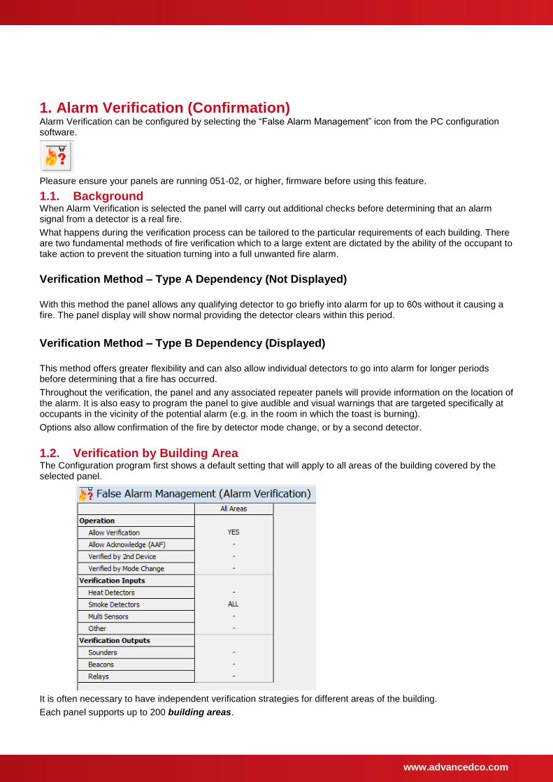
1.2. Verification by Building Area The Configuration program first shows a default setting that will apply to all areas of the building covered by the selected panel.
It is often necessary to have independent verification strategies for different areas of the building.
Each panel supports up to 200 building areas.
www.advancedco.com
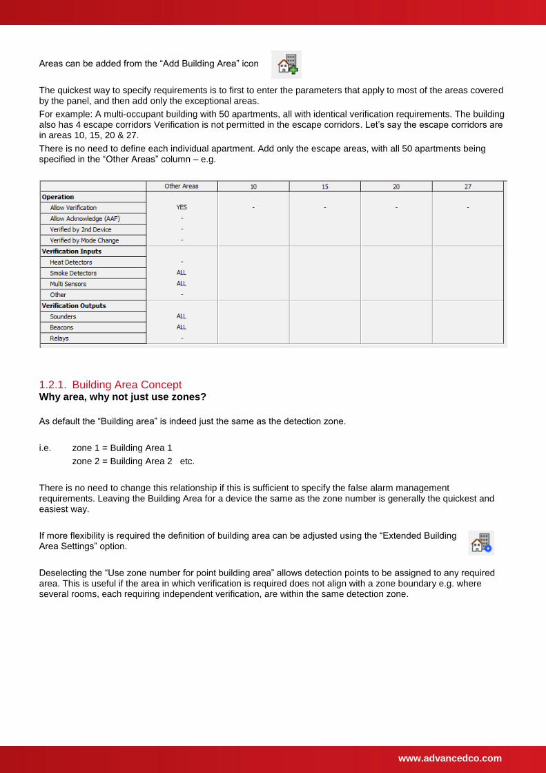
Areas can be added from the “Add Building Area” icon
The quickest way to specify requirements is to first to enter the parameters that apply to most of the areas covered by the panel, and then add only the exceptional areas.
For example: A multi-occupant building with 50 apartments, all with identical verification requirements. The building also has 4 escape corridors Verification is not permitted in the escape corridors. Let’s say the escape corridors are in areas 10, 15, 20 & 27.
There is no need to define each individual apartment. Add only the escape areas, with all 50 apartments being specified in the “Other Areas” column – e.g.
1.2.1. Building Area Concept Why area, why not just use zones?
As default the “Building area” is indeed just the same as the detection zone.
i.e. zone 1 = Building Area 1
zone 2 = Building Area 2 etc.
There is no need to change this relationship if this is sufficient to specify the false alarm management requirements. Leaving the Building Area for a device the same as the zone number is generally the quickest and easiest way.
If more flexibility is required the definition of building area can be adjusted using the “Extended Building Area Settings” option.
Deselecting the “Use zone number for point building area” allows detection points to be assigned to any required area. This is useful if the area in which verification is required does not align with a zone boundary e.g. where several rooms, each requiring independent verification, are within the same detection zone.
www.advancedco.com
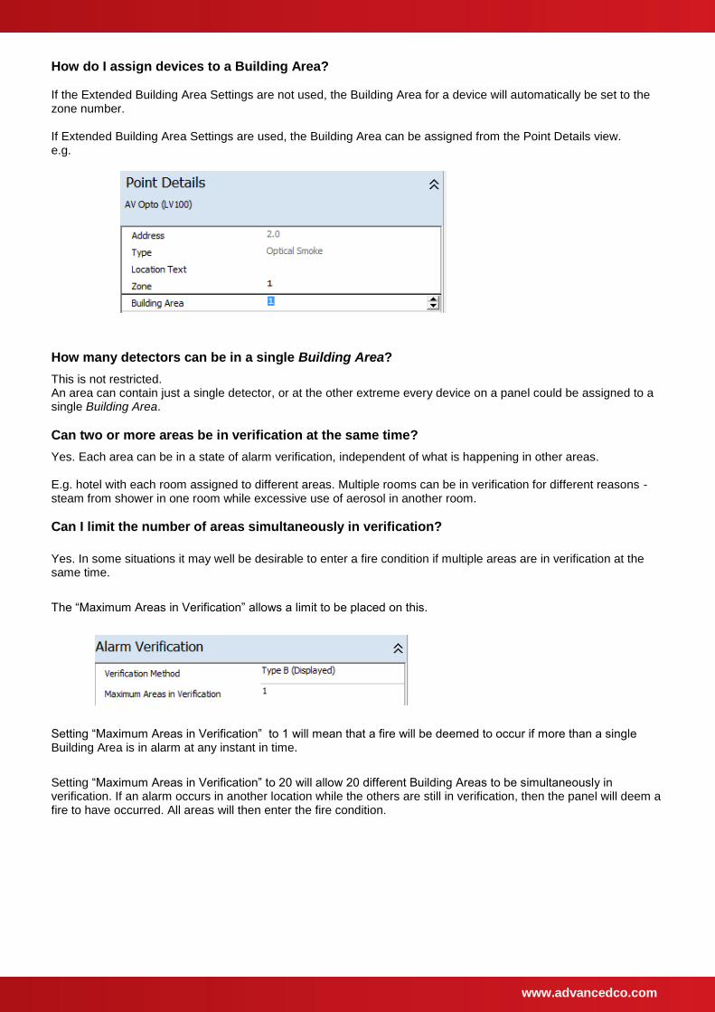
How do I assign devices to a Building Area? If the Extended Building Area Settings are not used, the Building Area for a device will automatically be set to the zone number. If Extended Building Area Settings are used, the Building Area can be assigned from the Point Details view. e.g.
How many detectors can be in a single Building Area?
This is not restricted. An area can contain just a single detector, or at the other extreme every device on a panel could be assigned to a single Building Area.
Can two or more areas be in verification at the same time?
Yes. Each area can be in a state of alarm verification, independent of what is happening in other areas. E.g. hotel with each room assigned to different areas. Multiple rooms can be in verification for different reasons - steam from shower in one room while excessive use of aerosol in another room.
Can I limit the number of areas simultaneously in verification?
Yes. In some situations it may well be desirable to enter a fire condition if multiple areas are in verification at the same time.
The “Maximum Areas in Verification” allows a limit to be placed on this.
Setting “Maximum Areas in Verification” to 1 will mean that a fire will be deemed to occur if more than a single Building Area is in alarm at any instant in time.
Setting “Maximum Areas in Verification” to 20 will allow 20 different Building Areas to be simultaneously in verification. If an alarm occurs in another location while the others are still in verification, then the panel will deem a fire to have occurred. All areas will then enter the fire condition.
www.advancedco.com
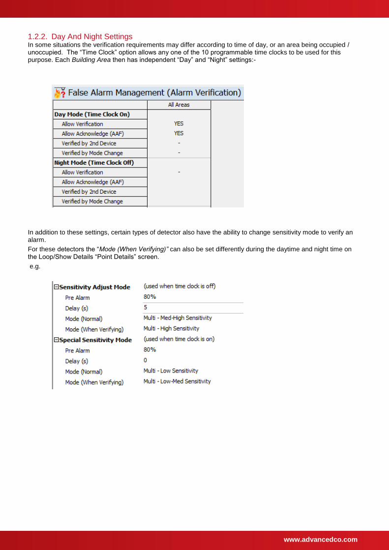
1.2.2. Day And Night Settings In some situations the verification requirements may differ according to time of day, or an area being occupied / unoccupied. The “Time Clock” option allows any one of the 10 programmable time clocks to be used for this purpose. Each Building Area then has independent “Day” and “Night” settings:-
In addition to these settings, certain types of detector also have the ability to change sensitivity mode to verify an alarm.
For these detectors the “Mode (When Verifying)” can also be set differently during the daytime and night time on the Loop/Show Details “Point Details” screen.
e.g.
www.advancedco.com
1.2.3. Adjustable Parameters for each Building Area
Operation Setting
Allow Verification Yes – The selected “Verification Inputs” will enter verification before a fire is confirmed
No – All detection devices in the area go immediately into fire alarm.
Allow Acknowledge
Yes – Alarms requiring extended time to clear or investigate can be acknowledged by occupants in the area, or from the control panel.
No – Alarm acknowledgment facility not used in this area.
Verified by 2nd Device
Yes – A fire alarm is confirmed immediately when a 2nd detector in the area signals an alarm.
No – More than one device can signal an alarm while the panel is still within the verification time.
Verified by Mode Change
Yes – Multimode detectors have the option to change their mode to the specified “Verification mode” during the verification process. If the alarm signal is also received from the detector once it has changed mode, a fire is immediately confirmed.
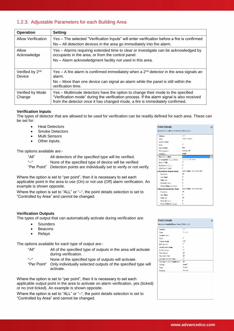
Verification Inputs The types of detector that are allowed to be used for verification can be readily defined for each area. These can be set for:
Heat Detectors
Smoke Detectors
Multi Sensors
Other inputs.
The options available are:-
“All” All detectors of the specified type will be verified.
“–“ None of the specified type of device will be verified
“Per Point” Detection points are individually set to verify or not verify.
Where the option is set to “per point”, then it is necessary to set each applicable point in the area to use (On) or not use (Off) alarm verification. An example is shown opposite.
Where the option is set to “ALL” or “–“, the point details selection is set to “Controlled by Area” and cannot be changed.
Verification Outputs The types of output that can automatically activate during verification are:
Sounders
Beacons
Relays
The options available for each type of output are:-
“All” All of the specified type of outputs in the area will activate during verification.
“–“ None of the specified type of outputs will activate.
“Per Point” Only individually selected outputs of the specified type will activate.
Where the option is set to “per point”, then it is necessary to set each applicable output point in the area to activate on alarm verification, yes (ticked) or no (not ticked). An example is shown opposite.
Where the option is set to “ALL” or “–“, the point details selection is set to “Controlled by Area” and cannot be changed.
www.advancedco.com
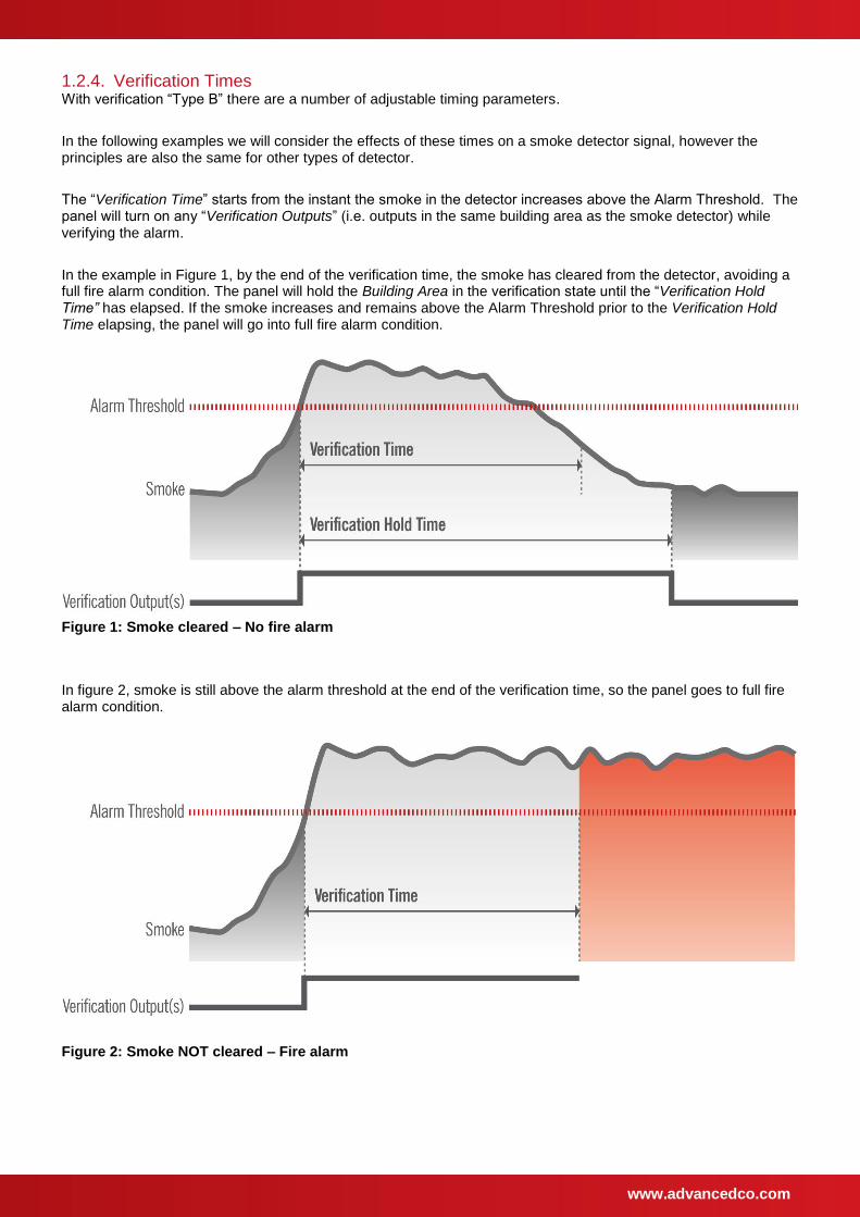
1.2.4. Verification Times With verification “Type B” there are a number of adjustable timing parameters.
In the following examples we will consider the effects of these times on a smoke detector signal, however the principles are also the same for other types of detector.
The “Verification Time” starts from the instant the smoke in the detector increases above the Alarm Threshold. The panel will turn on any “Verification Outputs” (i.e. outputs in the same building area as the smoke detector) while verifying the alarm.
In the example in Figure 1, by the end of the verification time, the smoke has cleared from the detector, avoiding a full fire alarm condition. The panel will hold the Building Area in the verification state until the “Verification Hold Time” has elapsed. If the smoke increases and remains above the Alarm Threshold prior to the Verification Hold Time elapsing, the panel will go into full fire alarm condition.
Figure 1: Smoke cleared – No fire alarm
In figure 2, smoke is still above the alarm threshold at the end of the verification time, so the panel goes to full fire alarm condition.
Figure 2: Smoke NOT cleared – Fire alarm
www.advancedco.com
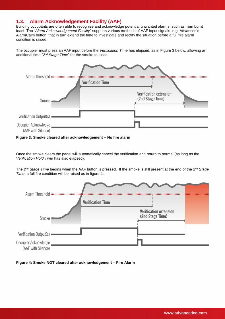
1.3. Alarm Acknowledgement Facility (AAF) Building occupants are often able to recognize and acknowledge potential unwanted alarms, such as from burnt toast. The “Alarm Acknowledgement Facility” supports various methods of AAF input signals, e.g. Advanced’s AlarmCalm button, that in turn extend the time to investigate and rectify the situation before a full fire alarm condition is raised.
The occupier must press an AAF input before the Verification Time has elapsed, as in Figure 3 below, allowing an additional time “2nd Stage Time” for the smoke to clear.
Figure 3: Smoke cleared after acknowledgement – No fire alarm
Once the smoke clears the panel will automatically cancel the verification and return to normal (as long as the Verification Hold Time has also elapsed).
The 2nd Stage Time begins when the AAF button is pressed. If the smoke is still present at the end of the 2nd Stage Time, a full fire condition will be raised as in figure 4.
Figure 4: Smoke NOT cleared after acknowledgement – Fire Alarm
www.advancedco.com
1.3.1. AlarmCalm – Alarm Acknowledgement from Loop Inputs AlarmCalm modules are loop powered devices and can be placed at any required address on the loop.
Placing an AlarmCalm pushbutton in each Building Area allows the occupants in that area to acknowledge a potential false alarm without effecting occupants in other areas.
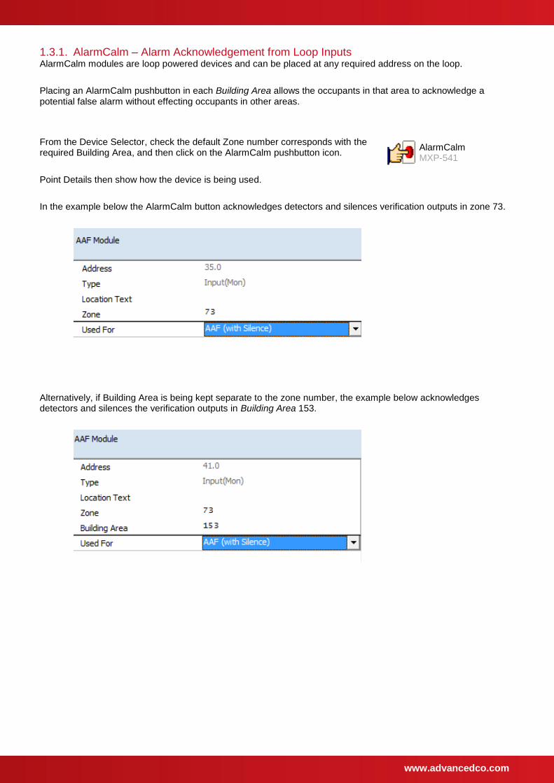
From the Device Selector, check the default Zone number corresponds with the required Building Area, and then click on the AlarmCalm pushbutton icon.
Point Details then show how the device is being used.
In the example below the AlarmCalm button acknowledges detectors and silences verification outputs in zone 73.
Alternatively, if Building Area is being kept separate to the zone number, the example below acknowledges detectors and silences the verification outputs in Building Area 153.
AlarmCalm MXP-541
www.advancedco.com
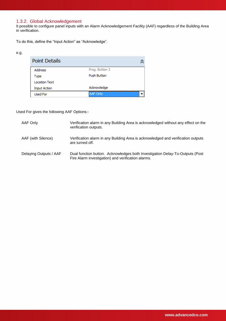
1.3.2. Global Acknowledgement It possible to configure panel inputs with an Alarm Acknowledgement Facility (AAF) regardless of the Building Area in verification.
To do this, define the “Input Action” as “Acknowledge”.
e.g.
Used For gives the following AAF Options:-
AAF Only Verification alarm in any Building Area is acknowledged without any effect on the verification outputs.
AAF (with Silence) Verification alarm in any Building Area is acknowledged and verification outputs are turned off.
Delaying Outputs / AAF Dual function button. Acknowledges both Investigation Delay-To-Outputs (Post Fire Alarm investigation) and verification alarms.
www.advancedco.com
1.4. Verification and Networks Each panel is configured with its own verification strategy.
This allows most verification settings to be changed without undue concern over how this may affect other panels on the network.
Verification information does pass over the network. As default, all nodes will be aware of verification alarms occurring at other nodes on the network. You may wish to control (limit) the effects of this in some situations.
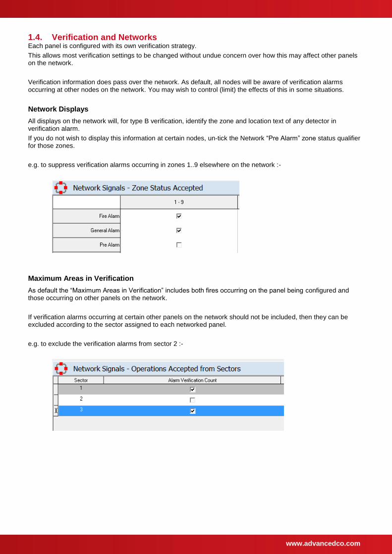
Network Displays
All displays on the network will, for type B verification, identify the zone and location text of any detector in verification alarm.
If you do not wish to display this information at certain nodes, un-tick the Network “Pre Alarm” zone status qualifier for those zones.
e.g. to suppress verification alarms occurring in zones 1..9 elsewhere on the network :-
Maximum Areas in Verification
As default the “Maximum Areas in Verification” includes both fires occurring on the panel being configured and those occurring on other panels on the network.
If verification alarms occurring at certain other panels on the network should not be included, then they can be excluded according to the sector assigned to each networked panel.
e.g. to exclude the verification alarms from sector 2 :-
www.advancedco.com
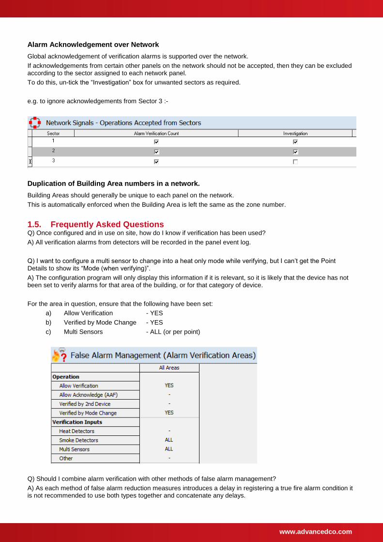
Alarm Acknowledgement over Network
Global acknowledgement of verification alarms is supported over the network.
If acknowledgements from certain other panels on the network should not be accepted, then they can be excluded according to the sector assigned to each network panel.
To do this, un-tick the “Investigation” box for unwanted sectors as required.
e.g. to ignore acknowledgements from Sector 3 :-
Duplication of Building Area numbers in a network.
Building Areas should generally be unique to each panel on the network.
This is automatically enforced when the Building Area is left the same as the zone number.
1.5. Frequently Asked Questions Q) Once configured and in use on site, how do I know if verification has been used?
A) All verification alarms from detectors will be recorded in the panel event log.
Q) I want to configure a multi sensor to change into a heat only mode while verifying, but I can’t get the Point Details to show its “Mode (when verifying)”.
A) The configuration program will only display this information if it is relevant, so it is likely that the device has not been set to verify alarms for that area of the building, or for that category of device.
For the area in question, ensure that the following have been set:
a) Allow Verification - YES
b) Verified by Mode Change - YES
c) Multi Sensors - ALL (or per point)
Q) Should I combine alarm verification with other methods of false alarm management?
A) As each method of false alarm reduction measures introduces a delay in registering a true fire alarm condition it is not recommended to use both types together and concatenate any delays.
www.advancedco.com
2. Investigation
Alarm Investigation can be configured by selecting the “False Alarm Management” icon from the PC configuration software.
Then select the “Delay to Outputs” button
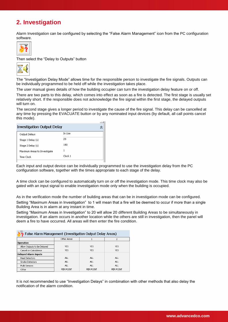
The “Investigation Delay Mode” allows time for the responsible person to investigate the fire signals. Outputs can be individually programmed to be held off while the investigation takes place.
The user manual gives details of how the building occupier can turn the investigation delay feature on or off.
There are two parts to this delay, which comes into effect as soon as a fire is detected. The first stage is usually set relatively short. If the responsible does not acknowledge the fire signal within the first stage, the delayed outputs will turn on.
The second stage gives a longer period to investigate the cause of the fire signal. This delay can be cancelled at any time by pressing the EVACUATE button or by any nominated input devices (by default, all call points cancel this mode).
Each input and output device can be individually programmed to use the investigation delay from the PC configuration software, together with the times appropriate to each stage of the delay.
A time clock can be configured to automatically turn on or off the investigation mode. This time clock may also be gated with an input signal to enable investigation mode only when the building is occupied.
As in the verification mode the number of building areas that can be in investigation mode can be configured.
Setting “Maximum Areas in Investigation” to 1 will mean that a fire will be deemed to occur if more than a single Building Area is in alarm at any instant in time.
Setting “Maximum Areas in Investigation” to 20 will allow 20 different Building Areas to be simultaneously in investigation. If an alarm occurs in another location while the others are still in investigation, then the panel will deem a fire to have occurred. All areas will then enter the fire condition.
It is not recommended to use “Investigation Delays” in combination with other methods that also delay the notification of the alarm condition.
www.advancedco.com
3. Detector Sensitivity
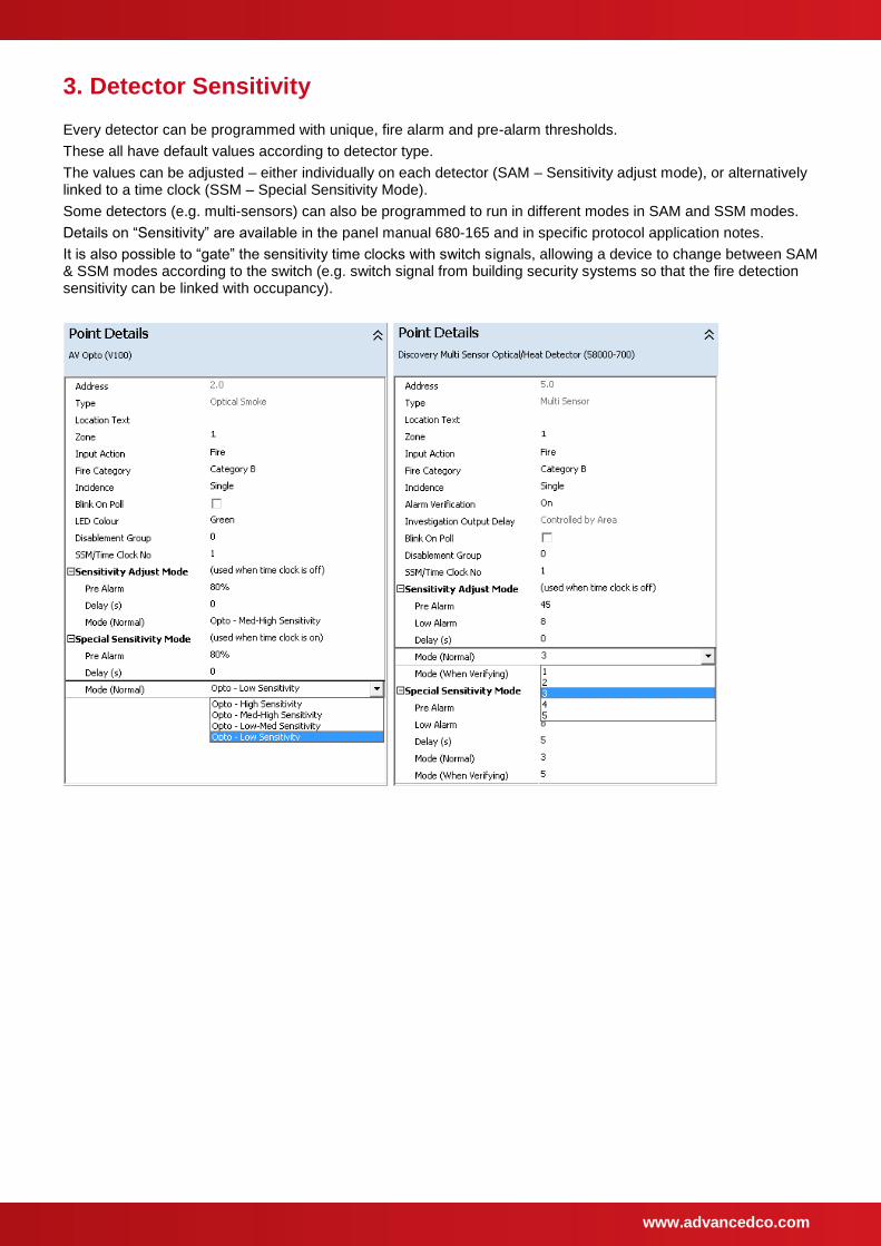
Every detector can be programmed with unique, fire alarm and pre-alarm thresholds.
These all have default values according to detector type.
The values can be adjusted – either individually on each detector (SAM – Sensitivity adjust mode), or alternatively linked to a time clock (SSM – Special Sensitivity Mode).
Some detectors (e.g. multi-sensors) can also be programmed to run in different modes in SAM and SSM modes.
Details on “Sensitivity” are available in the panel manual 680-165 and in specific protocol application notes.
It is also possible to “gate” the sensitivity time clocks with switch signals, allowing a device to change between SAM & SSM modes according to the switch (e.g. switch signal from building security systems so that the fire detection sensitivity can be linked with occupancy).
www.advancedco.com
4. Other Options
Q) I want to delay the activation of one or more outputs until a second fire alarm is recognized.
A) This can be configured using the Type C Dependency
This is commonly used to ensure that the outputs to fire routing or fire protection equipment are not activated until confirmed by the spread of fire or by the activation of a manual call point.
It can also be used in permanently staffed installations so that the activation of all sounders, except one located in the permanently staffed area, are delayed until either a second fire alarm occurs or the responsible person activates a call point or takes other appropriate measures to evacuate the building.
Examples:
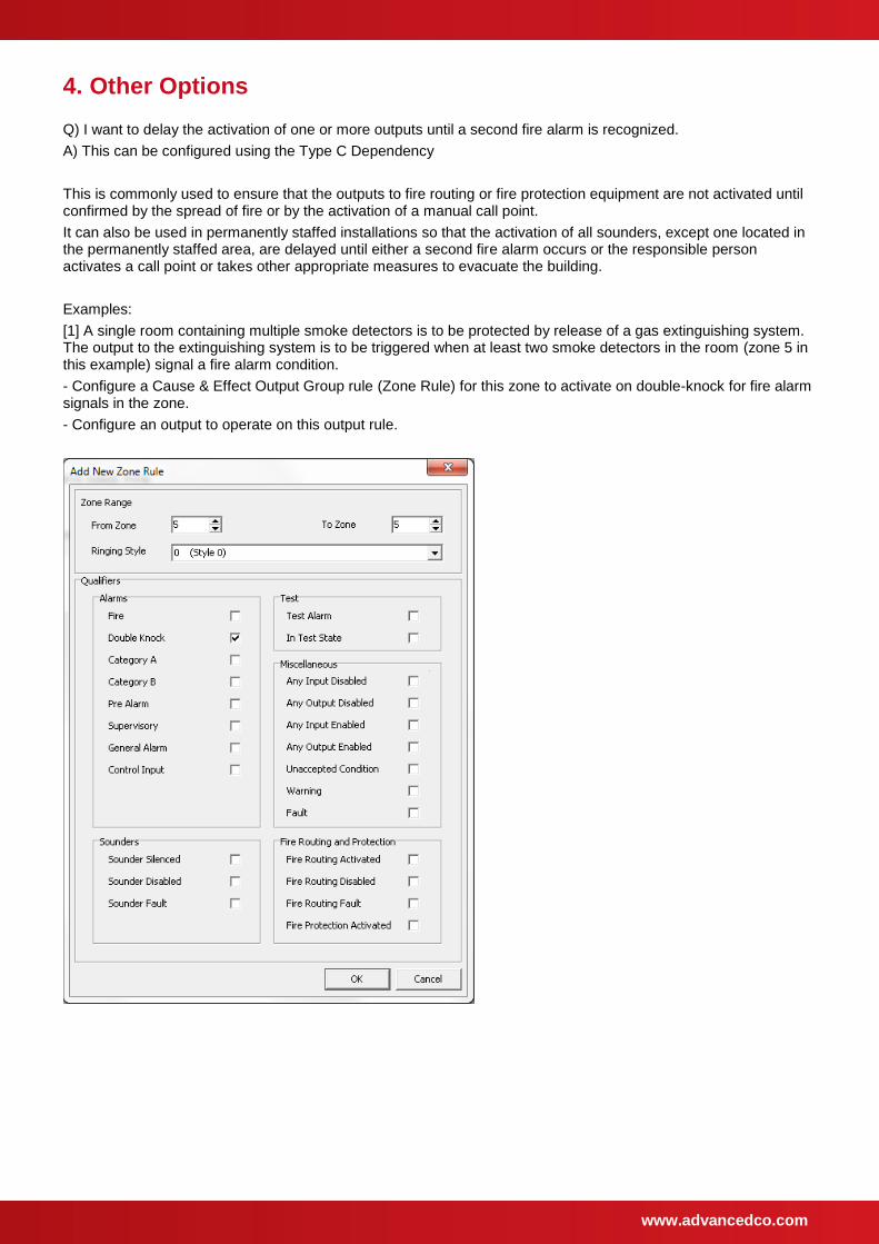
[1] A single room containing multiple smoke detectors is to be protected by release of a gas extinguishing system. The output to the extinguishing system is to be triggered when at least two smoke detectors in the room (zone 5 in this example) signal a fire alarm condition.
- Configure a Cause & Effect Output Group rule (Zone Rule) for this zone to activate on double-knock for fire alarm signals in the zone.
- Configure an output to operate on this output rule.
www.advancedco.com
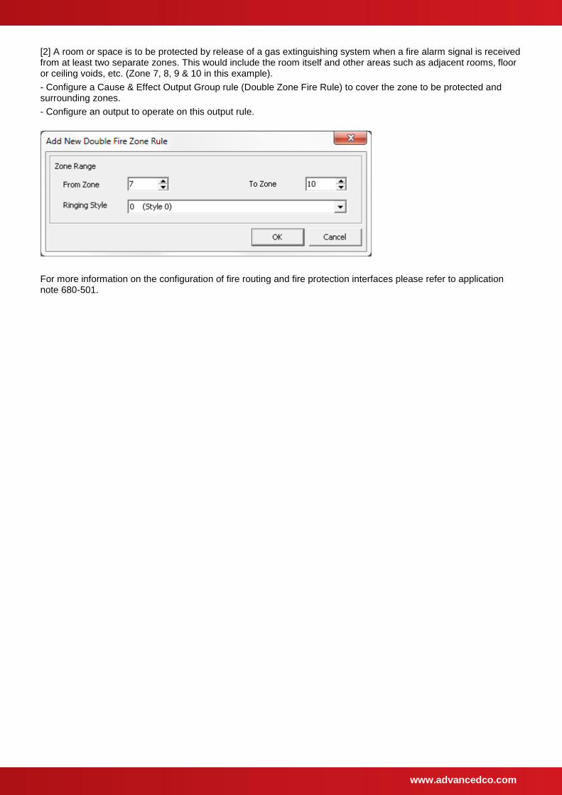
[2] A room or space is to be protected by release of a gas extinguishing system when a fire alarm signal is received from at least two separate zones. This would include the room itself and other areas such as adjacent rooms, floor or ceiling voids, etc. (Zone 7, 8, 9 & 10 in this example).
- Configure a Cause & Effect Output Group rule (Double Zone Fire Rule) to cover the zone to be protected and surrounding zones.
- Configure an output to operate on this output rule.
For more information on the configuration of fire routing and fire protection interfaces please refer to application note 680-501.