Embed Size (px)
Citation preview
Energies 2013, 6, 6077-6101; doi:10.3390/en6116077
energies ISSN 1996-1073
www.mdpi.com/journal/energies
Article
Experimental and Numerical Analysis of Thermal and Hygrometric Characteristics of Building Structures Employing Recycled Plastic Aggregates and Geopolymer Concrete
Francesco Colangelo, Giuseppina De Luca, Claudio Ferone and Alessandro Mauro *
Department of Engineering, University of Napoli “Parthenope”, Centro Direzionale,
Isola C4, 80143 Napoli, Italy; E-Mails: [email protected] (F.C.);
[email protected] (G.D.L.); [email protected] (C.F.)
* Author to whom correspondence should be addressed; E-Mail: [email protected];
Tel.: +39-081-547-6789; Fax: +39-081-547-6777.
Received: 18 July 2013; in revised form: 18 October 2013 / Accepted: 8 November 2013 /
Published: 21 November 2013
Abstract: The correct estimation of building energy consumptions is assuming an always
increasing importance, and a detailed reproduction of building structures, with all the
single components involved, is necessary to achieve this aim. In addition, the current
ecological development tries to limit the use of natural raw materials as building
components, in favor of alternative (waste) materials, which ensure significant advantages
from the economic, energetic and environmental point of views. In this work, dynamic heat
and vapor transport in a typical three-dimensional (3D) building structure, involving
different types of environmental-friendly concrete mixtures, have been simulated by using
finite elements. In particular, the authors propose to substitute part of the aggregates with
plastic waste and to use a fly ash based geopolymeric binder for the production of low
conductivity concrete, to be employed in eco-efficient buildings. Concrete produced with
natural limestone aggregates has been considered as the reference benchmark. The whole
characterization of the different types of concrete tested in the present work has been
obtained through laboratory experiments. The structure taken into account in the
simulations is a 3D thermal bridge, typical of building envelopes. The thermal and
hygrometric transient behavior of this structure, employing plastic waste in different
percentages and geopolymer concrete, has been analyzed by the authors.
OPEN ACCESS
Energies 2013, 6 6078
Keywords: geopolymer; lightweight concrete; thermal transmittance; thermal conductivity;
heat transfer; temperature contours; vapor permeability; numerical modeling; recycled
plastic waste aggregate
Nomenclature:
= specific heat capacity
= concrete mixture (numbers from 0 to 30 indicate the percentage of recycled plastic)
= geopolymeric concrete = convective heat transfer coefficient
= partial pressure of vapor (Pa)
= saturation pressure of water at temperature T (Pa) = heat flux (W/m2)
= thickness (m)
= temperature (K) = surface temperature (K)
= environment temperature (K)
Greek Symbols
= water vapor permeability
= thermal conductivity
= relative humidity
= density (kg/m3)
= time (s)
Subscripts
= initial
= bricks
= concrete
= exterior = equivalent
= interior
= steel
= vapor
= water
1. Introduction
The always increasing attention given to the concepts of sustainable development and energy
saving makes it necessary to adopt proper solutions to protect the environment and at the same time
c ( )( )J kg K⋅
0 30C −
G
ch ( )( )J kg K⋅
vp
( )satp T
qs
T
PT
T∞
δ ( )( )kg m s Pa⋅ ⋅
λ ( )( )W m K⋅
φρϑ
0bcoeeq
is
vw
Energies 2013, 6 6079
reduce the overall energy consumption needed for the human activities. The building process involves
high energy consumption and has significant effects on the environment. Therefore, the sustainable
development concept tries to limit the use of natural raw materials in building applications and to
increase the adoption of alternative materials, such as plastic wastes obtained from other industrial
production processes. In this way, recycled plastic waste can be used as aggregate for concrete,
offering significant advantages from the economic, energetic and environmental point of views.
These aspects assume a significant role, since plastic is used worldwide and an increase of plastic
consumption has been registered in all countries, with a consequent increase of plastic waste
production. For example, in 1996, about 12% in terms of weight of all municipal solid waste (MSW)
in the United States was composed of plastics [1]. The world’s annual consumption of plastic materials
increased from around 5 million tons in the 50s to nearly 100 million tons in 2001 [1]. Therefore, it is
evident that managing plastic waste is one of the most important problems of waste management, also
because this kind of waste is non-biodegradable and it is composed by many toxic chemicals
(especially cadmium and lead) that would produce significant pollution if not properly managed.
Moreover, the Italian Legislative Decree n. 152/2006 [2] encourages the recovery of solid waste as an
alternative to landfill disposal.
It is worth noting that a number of studies have dealt with the tuning of chemical-physics properties
of plastic materials in order to obtain eco-friendly materials and reduce energy requirements, for
example in the realization of OLED, PLED or FET [3–5].
Research is being conducted on the utilization of waste products in concrete. These waste products
include discarded tires, plastic, glass, steel, burnt foundry and sand [1]. Plastic could be used in various
applications, and efforts have been done to explore its use in concrete and asphalt. A review on waste
and recycled plastics, waste management options, and the effects of recycled plastic on the fresh and
hardened properties of concrete is available in [1,6].
A number of papers dealing with the experimental characterization of concrete mixtures employing
different kinds of recycled aggregates have been published in the last few years [7–20]. In fact, Behiry [13]
showed that by mixing recycled concrete aggregate (RCA) with traditional limestone aggregate (LSA),
the mechanical properties of the mixture can be improved, taking the unconfined compressive strength
as a quality indicator. Variables influencing the unconfined compressive strength such as cement
content, curing time and dry density play important roles to determine the performance of the mixture.
Specific treatments by using low concentration acid, aimed at producing high quality RCA for
structural concrete applications, are under investigation [14]. Waste polyethylene terephthalate (PET)
is deemed promising by the scientific community as an alternate binding material in place of the
commonly used ordinary Portland cement, and it is also studied together with composite
structures [15–19]. Furthermore, experimental data are often accompanied by numerical analysis in
order to investigate the mechanical behavior of RCA structures [17,20]. It is possible to further reduce the concrete carbon footprint by substituting the traditional cement
binder with a novel geopolymeric binder. The term “geopolymer” was introduced by Davidovits in the
late 1970s, and nowadays identifies a family of amorphous alkali or alkali-silicate activated
aluminosilicate binders of composition usually with and
(where M usually is Na or K) [21]. Setting and hardening mechanisms of geopolymeric
binders are quite different from those of cement based binders. In fact, the preparation of geopolymeric
2 2 3 2M O Al O SiOm n⋅ ⋅ 1m ≈2 6n≤ ≤
Energies 2013, 6 6080
binders is carried out by mixing reactive silico-aluminate materials with strongly alkaline solutions
such as alkali metal (Na, K) hydroxides or silicates. In this environment, the silico-aluminate reactive
materials are rapidly dissolved. A complex reaction mechanism follows, in which solubilized silica
and alumina condense with the ultimate formation of a three-dimensional network [21]. The synthesis
of geopolymers has been carried out starting from a wide variety of virgin raw materials, such as
metakaolin [22–24], natural clays [25] and other natural silico-aluminates [26], as well as industrial
process wastes such as coal fly ash [27–29] and metallurgical slag [30]. Geopolymer-based materials
are attractive because excellent mechanical properties, high early strength, high durability, freeze-thaw
resistance, low chloride diffusion rate, abrasion resistance, thermal stability and fire resistance, can be
achieved [31–33]. Due to their lower Ca content, they are also more resistant to acid attack than
Portland cement-based materials [34].
In addition, geopolymer-based materials are of great interest thanks to the reduced energy resources
needed for their manufacture, due to the reaction pathways involved, with consequent mitigation of
greenhouse gas (CO2) emissions. In fact, the production of kaolin-based or fly ash-based geopolymeric
cement generates an amount of CO2 up to six times or nine times less than Portland cement, respectively.
The result is a reduction of greenhouse gas emissions up to about 90% [35,36]. On the other hand,
a great deal of attention is given today to the issue of energy efficiency in buildings as demonstrated by
international and national directives [37–42], that require member states to ensure minimum energy
performance requirements for new and existing buildings. In particular, building envelopes must have good
insulation properties, attenuation and phase-shift capacity of the external loads. Therefore, maximum
values of the thermal transmittance and of the periodic thermal transmittance of building components must
be ensured [40,42]. In particular, vertical walls, horizontal walls and windows must respect the limiting
values of the thermal transmittance imposed by the National Legislative Decree n. 311/2006 [42],
depending on the climatic zones defined in the National Legislative Decree n. 192/2005 [41]. Instead, the
limiting value for the module of the periodic thermal transmittance of opaque walls assumes the fixed
value of [40]. In the case of upgrading the energy efficiency of existing buildings, the
interventions can cause an increase of the structures weight, with possible problems of the static
equilibrium. As a consequence, there is a need in the building sector to employ innovative and
eco-efficient materials, that allow at the same time to reduce thermal dispersions, temperature
oscillations and structures’ weights.
Therefore, the use of structural and non-structural alternative materials with lower thermal
conductivity and specific heat capacity than the traditional ones can contribute to reduce heat losses
and temperature oscillations of the building envelopes, with consequent reduction of energy
consumptions and related emissions. Moreover, the choice of recycled materials as alternative would
have a positive impact on both construction and recycling sectors, with consequent increase of
energetic efficiency on broad scale.
In the authors’ opinion, the development of new construction materials employing recycled plastics
assumes a crucial role in both the construction and the plastic recycling industries. These materials
could be used for building applications, as structural and non-structural parts of the envelope, ensuring
at the same time good thermal, hygrometric and mechanical properties, economic savings and
energetic advantages. Furthermore, the present eco-efficient concrete mixtures can contribute to reduce
( )20.20 W m K⋅
Energies 2013, 6 6081
the weight of building structures, given their reduced density, that is an important aspect to take into
account, especially with regards to seismic forces.
To the authors’ knowledge, numerical investigations of heat and mass transfer in three-dimensional
(3D) building structures employing concrete with recycled plastic aggregates or geopolymer as binder
are not available in the literature. Therefore, the authors have carried out laboratory experiments in
order to characterize different concrete mixtures in terms of mechanical, thermal and hygrometric
properties. In particular, the values of the following properties are reported in the present paper:
density, vapor permeability, thermal conductivity, specific heat capacity. These experimental data have
then been used in a numerical simulation code, based on finite elements, in order to reproduce the
transient behavior of a typical building structure, characterized by a 3D field of the quantities of
interest, defined as thermal bridge. This novel paper integrates the experiences of the authors
belonging to research groups, working in two research areas: materials sciences [7–10,23,25,29,33]
and thermal sciences [43–48].
The present paper is structured as follows: the next section describes the materials employed
in the experiments. Section 3 describes the experimental procedures used to measure the
thermo-hygrometric properties. In Section 4, the mathematical model employed is introduced. The
fifth section presents the main obtained results, while some conclusions are drawn in the last section.
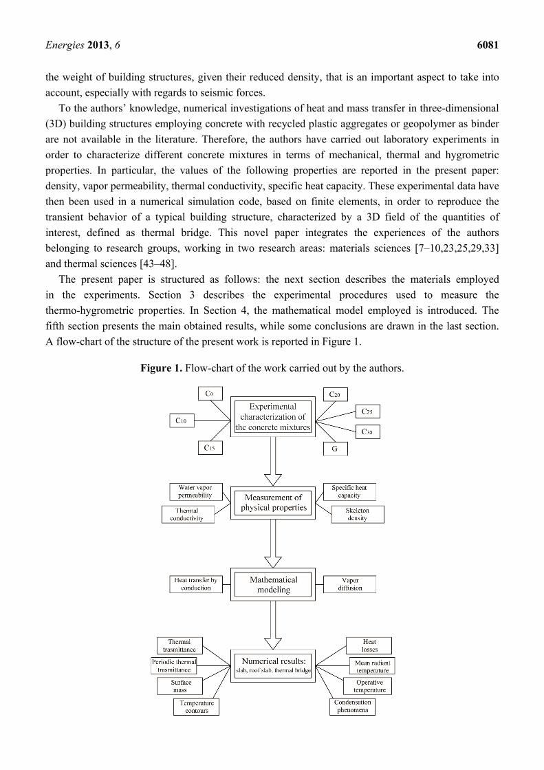
A flow-chart of the structure of the present work is reported in Figure 1.
Figure 1. Flow-chart of the work carried out by the authors.
Energies 2013, 6 6082
2. Materials Employed in the Experiments
This work proposes the use of plastic waste aggregate supplied by the company Ri.genera s.r.l.
(Marigliano (NA), Italy) for the production of low conductivity concrete for eco-efficient building
applications. A natural limestone aggregate has been used as reference benchmark. The cement
used was CEM II/A-L 42,5 R, according to European Standards EN-197-1 [49], produced by the
Italcementi factory (Matera, Italy).
The fine and coarse aggregates were crushed limestone, with density values of 2351 and 2372 kg/m3,
and water absorption capacity of 2.05% and 0.63%, respectively. They were separated into different size
fractions that were then recombined to a specific grading. The fly ash employed was supplied by
ENEL S.p.A. (Brindisi, Italy). The respective chemical compositions are reported in Table 1.
Table 1. Chemical composition of materials (wt%).
Oxides CEM Fly ash Marble sludge
CaO 60.84 4.32 53.76 SiO2 20.66 53.75 2.13 Al2O3 4.89 28.12 0.12 Fe2O3 3.24 6.99 0.69 MgO 1.94 1.59 0.15 SO3 2.95 - -
Na2O 0.12 0.87 - K2O 0.84 1.89 - Cl− 0.94 - -
LoI * 5.76 6.01 42.74
* Loss on ignition.
The superplasticizer used was an acrylic one with 40% solid content and a specific gravity of
1.2 kg/dm3. The water content of the superplasticizer was considered during the mix-design phase.
Six conventional concrete mixtures have been designed in addition to a geopolymeric concrete
characterized by S5 consistency class [50]. The workability was kept constant for all the mixtures.
Table 2 shows mixture proportions for all the concrete specimens.
Table 2. Mixture proportions of concrete samples.
Mixture G C0 C10 C15 C20 C25 C30
Cement (kg/m3) - 300 300 300 300 300 300 Natural aggregate (kg/m3) 854 1648 1351 1293 1227 1203 1101 Plastic aggregate (kg/m3) - 0 70 105 140 175 210
Fly ash (kg/m3) 208 90 90 90 90 90 90 Marble sludge (kg/m3) - 146 152 163 171 176 183
Activating solution (kg/m3) 138 - - - - - - Acrylic admixture (L/m3) - 6.86 7.26 8.05 8.91 8.75 9.95
Water/cement N.A. 0.5 0.5 0.5 0.5 0.5 0.5
The activating solution employed to prepare the geopolymer concrete has the following composition: and was prepared starting from a commercial sodium silicate 2 2 2Na O 0.90SiO 14.7H O⋅ ⋅
Energies 2013, 6 6083
solution supplied by Prochin Italia s.r.l. (Marcianise (CE), Italy) and a 10 M NaOH
solution prepared by using NaOH in pellets (analytical R grade, Baker, Milan, Italy). Geopolymer
specimens have been cured at room temperature, completely wrapped in a PVC film, in order to
prevent any early water evaporation.
The mix proportions of the concrete mixtures are reported in Table 2. In this table, the first part of
the mixture code gives information on the kind of concrete (C indicate conventional concrete,
G geopolymeric concrete), while the second part indicates the percentage of waste plastic employed as
aggregate (from 0% to 30 %). The mixtures used in the present work have similar mixture proportions
in terms of the aggregate to cement ratio. The water to cement ratio was kept constant at 0.5 for all the
cement based concrete mixtures.
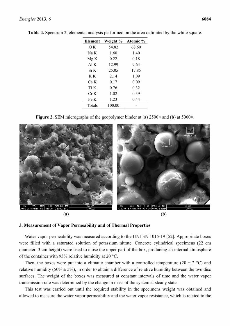
In order to assess the correct development of the geopolymerization process, 28 days cured
specimens were analyzed by Scanning Electron Microscopy (SEM) and Energy Dispersive
Spectroscopy (EDS) elemental analysis. SEM micrographs reported in Figure 2 refer to the binder
matrix and show a typical fly ash based geopolymer microstructure [51]. A cementitious matrix
constituted by the reaction products between the sodium silicate solution and the alumino-silicate
precursors can be observed from the figure, and its chemical composition, as derived from the
elemental analysis, is reported in Table 3. Several unreacted fly ash particles are observed to coexist
with reaction products and with a few particles attacked by the alkaline solution but which maintain
their spherical shape. The chemical composition of the spherical fly ash particles, as derived from the
elemental analysis, is reported in Table 4. It may be noticed the higher percentage of sodium in the
spectrum 1, arising from the polycondensation reaction involving fly ash and sodium silicate solution.
Table 3. Spectrum 1, elemental analysis performed on the area delimited by the white square.
Element Weight % Atomic %
C K 4.69 7.52 O K 51.83 62.46 Na K 9.64 8.08 Mg K 0.38 0.30 Al K 7.04 5.03 Si K 20.41 14.01 P K 0.15 0.09 S K 0.21 0.13 K K 1.25 0.62 Ca K 1.31 0.63 Ti K 0.40 0.16 Cr K 1.20 0.45 Fe K 1.49 0.51
Totals 100.00 -
( )2 2SiO / Na O=3.3
Energies 2013, 6 6084
Table 4. Spectrum 2, elemental analysis performed on the area delimited by the white square.
Element Weight % Atomic %
O K 54.82 68.60 Na K 1.60 1.40 Mg K 0.22 0.18 Al K 12.99 9.64 Si K 25.05 17.85 K K 2.14 1.09 Ca K 0.17 0.09 Ti K 0.76 0.32 Cr K 1.02 0.39 Fe K 1.23 0.44
Totals 100.00 -
Figure 2. SEM micrographs of the geopolymer binder at (a) 2500× and (b) at 5000×.
(a) (b)
3. Measurement of Vapor Permeability and of Thermal Properties
Water vapor permeability was measured according to the UNI EN 1015-19 [52]. Appropriate boxes
were filled with a saturated solution of potassium nitrate. Concrete cylindrical specimens (22 cm
diameter, 3 cm height) were used to close the upper part of the box, producing an internal atmosphere
of the container with 93% relative humidity at 20 °C.
Then, the boxes were put into a climatic chamber with a controlled temperature (20 ± 2 °C) and
relative humidity (50% ± 5%), in order to obtain a difference of relative humidity between the two disc
surfaces. The weight of the boxes was measured at constant intervals of time and the water vapor
transmission rate was determined by the change in mass of the system at steady state.
This test was carried out until the required stability in the specimens weight was obtained and
allowed to measure the water vapor permeability and the water vapor resistance, which is related to the
Energies 2013, 6 6085
material’s reluctance to let water vapor to pass through. High water vapor resistance values indicate
high resistance to water vapor transmission.
The thermal conductivity and the specific heat capacity of the six concrete mixtures and the
geopolymer were measured by using the TPS 1500 Thermal Conductivity System (ThermTest Inc.,
Fredericton, NB, Canada) This instrument has the following characteristics declared by the manufacturer: thermal conductivity measurement range 0.001 to 20 , specific heat capacity
measurement up to 5 , reproducibility typically better than 1%, accuracy better than 5%.
4. The Mathematical Model
The mathematical model employed in the present work for the simulation of heat and mass transfer
through a three-dimensional (3D) thermal bridge, characterized by the presence of the materials
described in the previous sections, consists in the unsteady equations for heat and vapor transport
through homogenous permeable media. The following governing equations are written for each
isotropic homogeneous material that is found in a typical building envelope:
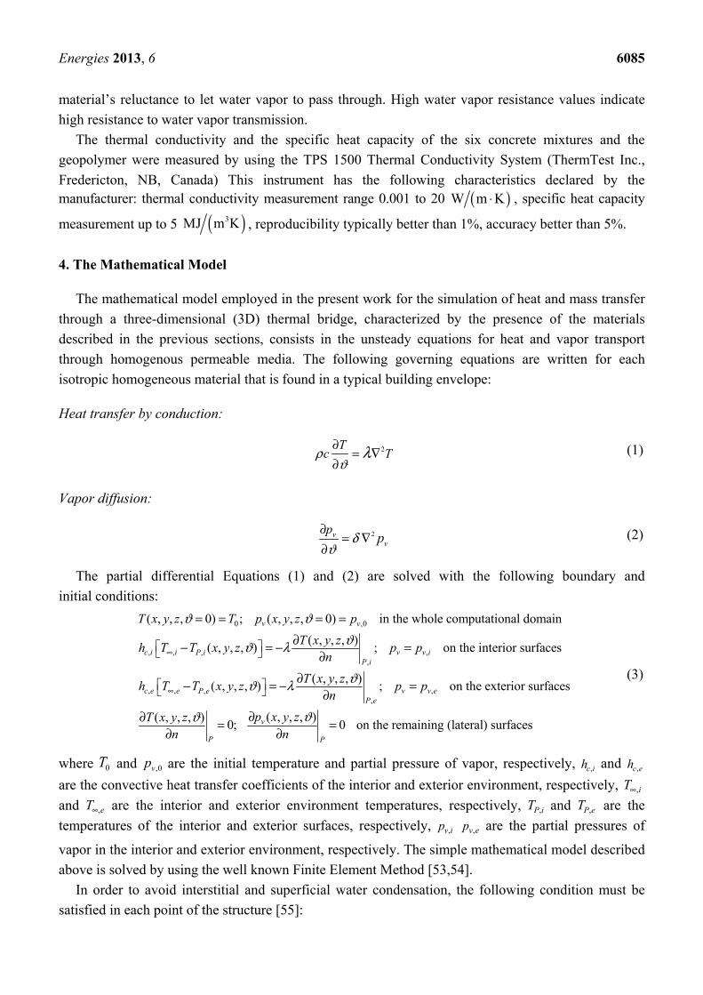
Heat transfer by conduction:
(1)
Vapor diffusion:
(2)
The partial differential Equations (1) and (2) are solved with the following boundary and
initial conditions:
(3)
where and are the initial temperature and partial pressure of vapor, respectively, and
are the convective heat transfer coefficients of the interior and exterior environment, respectively,
and are the interior and exterior environment temperatures, respectively, and are the
temperatures of the interior and exterior surfaces, respectively, are the partial pressures of
vapor in the interior and exterior environment, respectively. The simple mathematical model described
above is solved by using the well known Finite Element Method [53,54].
In order to avoid interstitial and superficial water condensation, the following condition must be
satisfied in each point of the structure [55]:
( )W m K⋅
( )3MJ m K
2∂= ∇
∂ρ
ϑλT
c T
2∂= ∇
∂δ
ϑv
v
pp
0 ,0
, , ,,,
, , ,,,
( , , , 0) ; ( , , , 0) in the whole computational domain
( , , , )( , , , ) ; on the interior surfaces
( , , , )( , , , ) ; on
v v
c i i v v iP iP i
c e e v v eP eP e
T x y z T p x y z p
T x y zh T T x y z p p
n
T x y zh T T x y z p p
n
ϑ ϑϑϑ λ
ϑϑ λ
∞
∞
= = = =
∂− = − =∂
∂− = − =∂
the exterior surfaces
( , , , )( , , , )0; 0 on the remaining (lateral) surfacesv
P P
p x y zT x y zn n
ϑϑ ∂∂ = =∂ ∂
0T ,0vp ,c ih ,c eh
,iT∞
,eT∞ ,P iT ,P eT
,v ip ,v ep
Energies 2013, 6 6086
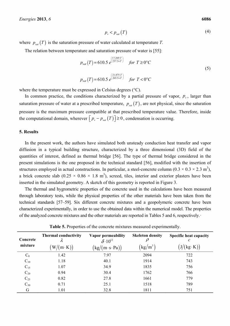
(4)
where is the saturation pressure of water calculated at temperature T.
The relation between temperature and saturation pressure of water is [55]:
(5)
where the temperature must be expressed in Celsius degrees (°C). In common practice, the conditions characterized by a partial pressure of vapor, , larger than
saturation pressure of water at a prescribed temperature, , are not physical, since the saturation
pressure is the maximum pressure compatible at that prescribed temperature value. Therefore, inside
the computational domain, wherever , condensation is occurring.
5. Results
In the present work, the authors have simulated both unsteady conduction heat transfer and vapor
diffusion in a typical building structure, characterized by a three dimensional (3D) field of the
quantities of interest, defined as thermal bridge [56]. The type of thermal bridge considered in the
present simulations is the one proposed in the technical standard [56], modified with the insertion of
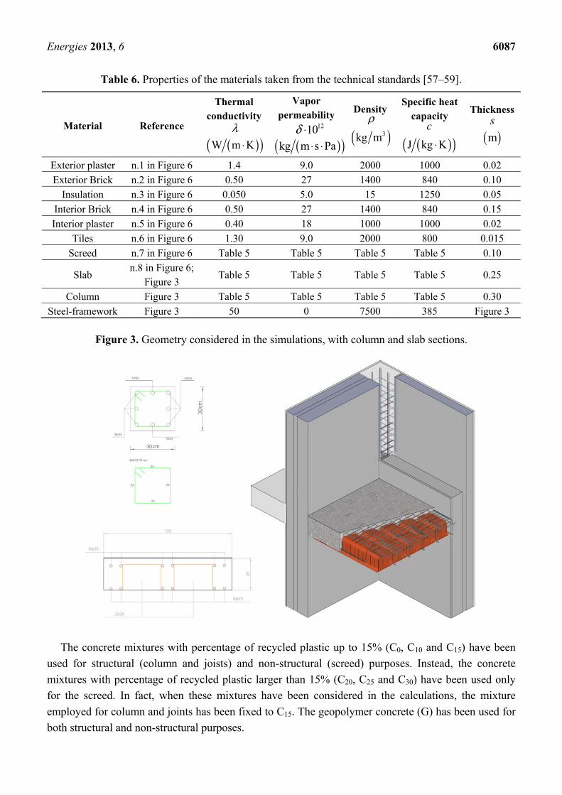
structures employed in actual constructions. In particular, a steel-concrete column (0.3 × 0.3 × 2.3 m3),
a brick concrete slab (0.25 × 0.86 × 1.8 m3), screed, tiles, interior and exterior plasters have been
inserted in the simulated geometry. A sketch of this geometry is reported in Figure 3.
The thermal and hygrometric properties of the concrete used in the calculations have been measured
through laboratory tests, while the physical properties of the other materials have been taken from the
technical standards [57–59]. Six different concrete mixtures and a geopolymeric concrete have been
characterized experimentally, in order to use the obtained data within the numerical model. The properties
of the analyzed concrete mixtures and the other materials are reported in Tables 5 and 6, respectively.·
Table 5. Properties of the concrete mixtures measured experimentally.
Concrete mixture
Thermal conductivity
Vapor permeability Skeleton density Specific heat capacity
C0 1.42 7.97 2094 722 C10 1.18 40.1 1914 743 C15 1.07 34.9 1835 756 C20 0.94 30.4 1762 766 C25 0.82 27.8 1661 779 C30 0.71 25.1 1518 789 G 1.01 32.8 1811 751
( )<v satp p T
( )satp T
( )
( )
17.269237.3
21.875265.5
610.5 0
610.5 0
TT
TT
sat
sat
p T e for T C
p T e for T C
⋅+
⋅+
= ≥ °
= < °
vp
( )satp T
( ) 0v satp p T− ≥
λ( )( )W m K⋅
1210δ ⋅( )( )kg m s Pa⋅ ⋅
ρ
( )3kg m
c
( )( )J kg K⋅
Energies 2013, 6 6087
Table 6. Properties of the materials taken from the technical standards [57–59].
Material Reference
Thermal conductivity
Vapor permeability
Density Specific heat
capacity
Thickness
Exterior plaster n.1 in Figure 6 1.4 9.0 2000 1000 0.02
Exterior Brick n.2 in Figure 6 0.50 27 1400 840 0.10
Insulation n.3 in Figure 6 0.050 5.0 15 1250 0.05
Interior Brick n.4 in Figure 6 0.50 27 1400 840 0.15
Interior plaster n.5 in Figure 6 0.40 18 1000 1000 0.02
Tiles n.6 in Figure 6 1.30 9.0 2000 800 0.015
Screed n.7 in Figure 6 Table 5 Table 5 Table 5 Table 5 0.10
Slab n.8 in Figure 6;
Figure 3 Table 5 Table 5 Table 5 Table 5 0.25
Column Figure 3 Table 5 Table 5 Table 5 Table 5 0.30
Steel-framework Figure 3 50 0 7500 385 Figure 3
Figure 3. Geometry considered in the simulations, with column and slab sections.
The concrete mixtures with percentage of recycled plastic up to 15% (C0, C10 and C15) have been
used for structural (column and joists) and non-structural (screed) purposes. Instead, the concrete
mixtures with percentage of recycled plastic larger than 15% (C20, C25 and C30) have been used only
for the screed. In fact, when these mixtures have been considered in the calculations, the mixture
employed for column and joints has been fixed to C15. The geopolymer concrete (G) has been used for
both structural and non-structural purposes.
λ( )( )W m K⋅
1210δ ⋅( )( )kg m s Pa⋅ ⋅
ρ
( )3kg mc
( )( )J kg K⋅
s
( )m
Energies 2013, 6 6088
Before presenting the results obtained by using the 3D numerical model, some considerations on
thermal transmittance, periodic thermal transmittance and weight reduction for slabs employing the
present innovative concrete mixtures have been reported in the following section.
5.1. Reduction of Thermal Transmittance, Periodic Thermal Transmittance and Weight
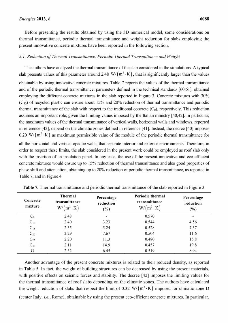
The authors have analyzed the thermal transmittance of the slab considered in the simulations. A typical
slab presents values of this parameter around 2.48 , that is significantly larger than the values
obtainable by using innovative concrete mixtures. Table 7 reports the values of the thermal transmittance
and of the periodic thermal transmittance, parameters defined in the technical standards [60,61], obtained
employing the different concrete mixtures in the slab reported in Figure 3. Concrete mixtures with 30%
(C30) of recycled plastic can ensure about 15% and 20% reduction of thermal transmittance and periodic
thermal transmittance of the slab with respect to the traditional concrete (C0), respectively. This reduction
assumes an important role, given the limiting values imposed by the Italian ministry [40,42]. In particular,
the maximum values of the thermal transmittance of vertical walls, horizontal walls and windows, reported
in reference [42], depend on the climatic zones defined in reference [41]. Instead, the decree [40] imposes
0.20 as maximum permissible value of the module of the periodic thermal transmittance for
all the horizontal and vertical opaque walls, that separate interior and exterior environments. Therefore, in
order to respect these limits, the slab considered in the present work could be employed as roof slab only
with the insertion of an insulation panel. In any case, the use of the present innovative and eco-efficient
concrete mixtures would ensure up to 15% reduction of thermal transmittance and also good properties of
phase shift and attenuation, obtaining up to 20% reduction of periodic thermal transmittance, as reported in
Table 7, and in Figure 4.
Table 7. Thermal transmittance and periodic thermal transmittance of the slab reported in Figure 3.
Concrete mixture
Thermal transmittance
Percentage reduction
(%)
Periodic thermal transmittance
Percentage reduction
(%)
C0 2.48 - 0.570 - C10 2.40 3.23 0.544 4.56 C15 2.35 5.24 0.528 7.37 C20 2.29 7.67 0.504 11.6 C25 2.20 11.3 0.480 15.8 C30 2.11 14.9 0.457 19.8 G 2.32 6.45 0.519 8.94
Another advantage of the present concrete mixtures is related to their reduced density, as reported
in Table 5. In fact, the weight of building structures can be decreased by using the present materials,
with positive effects on seismic forces and stability. The decree [42] imposes the limiting values for
the thermal transmittance of roof slabs depending on the climatic zones. The authors have calculated
the weight reduction of slabs that respect the limit of 0.32 imposed for climatic zone D
(center Italy, i.e., Rome), obtainable by using the present eco-efficient concrete mixtures. In particular,
( )2W/ m K⋅
( )2W/ m K⋅
( )2W/ m K⋅ ( )2W/ m K⋅
( )2W/ m K⋅
Energies 2013, 6 6089
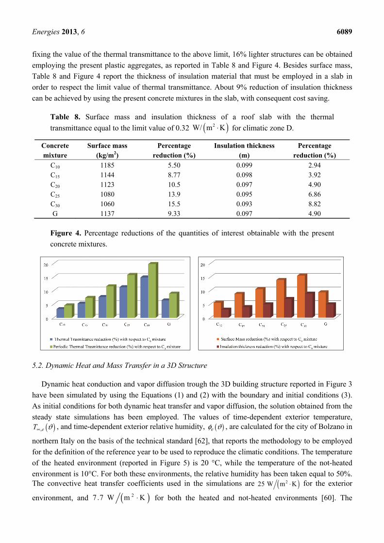
fixing the value of the thermal transmittance to the above limit, 16% lighter structures can be obtained
employing the present plastic aggregates, as reported in Table 8 and Figure 4. Besides surface mass,
Table 8 and Figure 4 report the thickness of insulation material that must be employed in a slab in
order to respect the limit value of thermal transmittance. About 9% reduction of insulation thickness
can be achieved by using the present concrete mixtures in the slab, with consequent cost saving.
Table 8. Surface mass and insulation thickness of a roof slab with the thermal
transmittance equal to the limit value of 0.32 for climatic zone D.
Concrete mixture
Surface mass (kg/m2)
Percentage reduction (%)
Insulation thickness (m)
Percentage reduction (%)
C10 1185 5.50 0.099 2.94 C15 1144 8.77 0.098 3.92 C20 1123 10.5 0.097 4.90 C25 1080 13.9 0.095 6.86 C30 1060 15.5 0.093 8.82 G 1137 9.33 0.097 4.90
Figure 4. Percentage reductions of the quantities of interest obtainable with the present
concrete mixtures.
5.2. Dynamic Heat and Mass Transfer in a 3D Structure
Dynamic heat conduction and vapor diffusion trough the 3D building structure reported in Figure 3
have been simulated by using the Equations (1) and (2) with the boundary and initial conditions (3).
As initial conditions for both dynamic heat transfer and vapor diffusion, the solution obtained from the
steady state simulations has been employed. The values of time-dependent exterior temperature, , and time-dependent exterior relative humidity, , are calculated for the city of Bolzano in
northern Italy on the basis of the technical standard [62], that reports the methodology to be employed
for the definition of the reference year to be used to reproduce the climatic conditions. The temperature
of the heated environment (reported in Figure 5) is 20 °C, while the temperature of the not-heated
environment is 10°C. For both these environments, the relative humidity has been taken equal to 50%. The convective heat transfer coefficients used in the simulations are for the exterior
environment, and for both the heated and not-heated environments [60]. The
( )2W/ m K⋅
( ),eT ϑ∞ ( )eφ ϑ
( )225 W m K⋅
( )27 .7 W m K⋅
Energies 2013, 6 6090
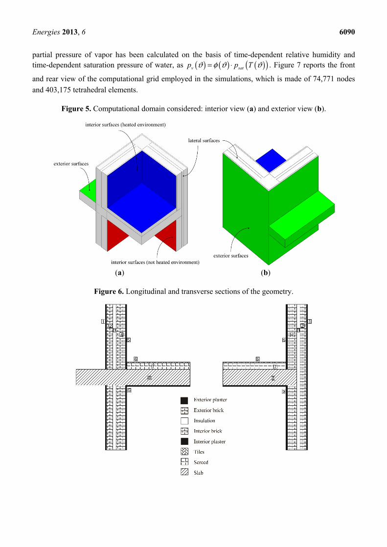
partial pressure of vapor has been calculated on the basis of time-dependent relative humidity and time-dependent saturation pressure of water, as . Figure 7 reports the front
and rear view of the computational grid employed in the simulations, which is made of 74,771 nodes
and 403,175 tetrahedral elements.
Figure 5. Computational domain considered: interior view (a) and exterior view (b).
(a) (b)
Figure 6. Longitudinal and transverse sections of the geometry.
( ) ( ) ( )( )v satp p Tϑ φ ϑ ϑ= ⋅
Energies 2013, 6 6091
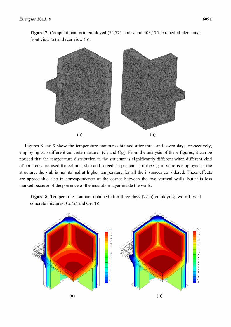
Figure 7. Computational grid employed (74,771 nodes and 403,175 tetrahedral elements):
front view (a) and rear view (b).
(a) (b)
Figures 8 and 9 show the temperature contours obtained after three and seven days, respectively,
employing two different concrete mixtures (C0 and C30). From the analysis of these figures, it can be
noticed that the temperature distribution in the structure is significantly different when different kind
of concretes are used for column, slab and screed. In particular, if the C30 mixture is employed in the
structure, the slab is maintained at higher temperature for all the instances considered. These effects
are appreciable also in correspondence of the corner between the two vertical walls, but it is less
marked because of the presence of the insulation layer inside the walls.
Figure 8. Temperature contours obtained after three days (72 h) employing two different
concrete mixtures: C0 (a) and C30 (b).
(a) (b)
Energies 2013, 6 6092
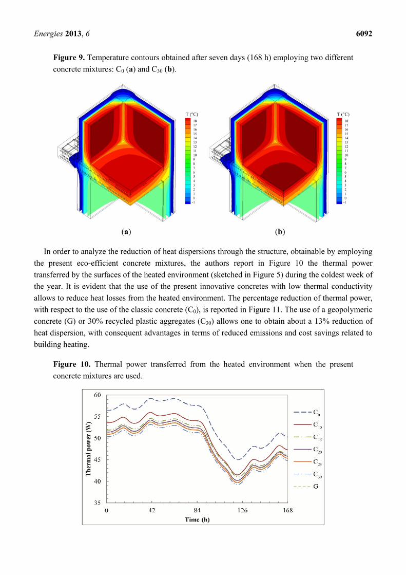
Figure 9. Temperature contours obtained after seven days (168 h) employing two different
concrete mixtures: C0 (a) and C30 (b).
(a) (b)
In order to analyze the reduction of heat dispersions through the structure, obtainable by employing
the present eco-efficient concrete mixtures, the authors report in Figure 10 the thermal power
transferred by the surfaces of the heated environment (sketched in Figure 5) during the coldest week of
the year. It is evident that the use of the present innovative concretes with low thermal conductivity
allows to reduce heat losses from the heated environment. The percentage reduction of thermal power,
with respect to the use of the classic concrete (C0), is reported in Figure 11. The use of a geopolymeric
concrete (G) or 30% recycled plastic aggregates (C30) allows one to obtain about a 13% reduction of
heat dispersion, with consequent advantages in terms of reduced emissions and cost savings related to
building heating.
Figure 10. Thermal power transferred from the heated environment when the present
concrete mixtures are used.
Energies 2013, 6 6093
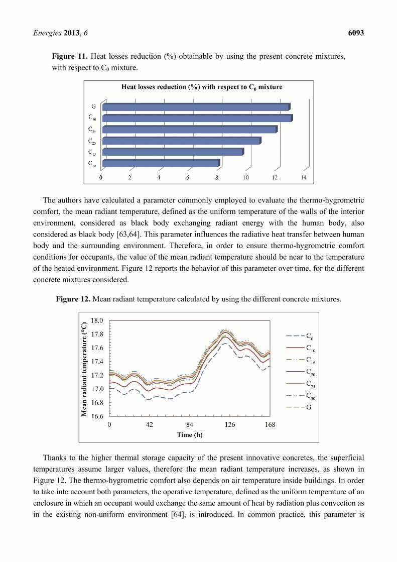
Figure 11. Heat losses reduction (%) obtainable by using the present concrete mixtures,
with respect to C0 mixture.
The authors have calculated a parameter commonly employed to evaluate the thermo-hygrometric
comfort, the mean radiant temperature, defined as the uniform temperature of the walls of the interior
environment, considered as black body exchanging radiant energy with the human body, also
considered as black body [63,64]. This parameter influences the radiative heat transfer between human
body and the surrounding environment. Therefore, in order to ensure thermo-hygrometric comfort
conditions for occupants, the value of the mean radiant temperature should be near to the temperature
of the heated environment. Figure 12 reports the behavior of this parameter over time, for the different
concrete mixtures considered.
Figure 12. Mean radiant temperature calculated by using the different concrete mixtures.
Thanks to the higher thermal storage capacity of the present innovative concretes, the superficial
temperatures assume larger values, therefore the mean radiant temperature increases, as shown in
Figure 12. The thermo-hygrometric comfort also depends on air temperature inside buildings. In order
to take into account both parameters, the operative temperature, defined as the uniform temperature of an
enclosure in which an occupant would exchange the same amount of heat by radiation plus convection as
in the existing non-uniform environment [64], is introduced. In common practice, this parameter is
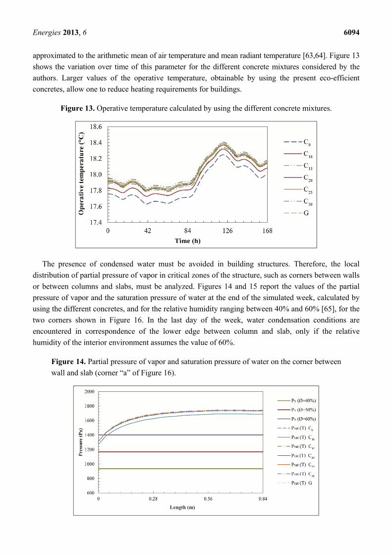
Energies 2013, 6 6094
approximated to the arithmetic mean of air temperature and mean radiant temperature [63,64]. Figure 13
shows the variation over time of this parameter for the different concrete mixtures considered by the
authors. Larger values of the operative temperature, obtainable by using the present eco-efficient
concretes, allow one to reduce heating requirements for buildings.
Figure 13. Operative temperature calculated by using the different concrete mixtures.
The presence of condensed water must be avoided in building structures. Therefore, the local
distribution of partial pressure of vapor in critical zones of the structure, such as corners between walls
or between columns and slabs, must be analyzed. Figures 14 and 15 report the values of the partial
pressure of vapor and the saturation pressure of water at the end of the simulated week, calculated by
using the different concretes, and for the relative humidity ranging between 40% and 60% [65], for the
two corners shown in Figure 16. In the last day of the week, water condensation conditions are
encountered in correspondence of the lower edge between column and slab, only if the relative
humidity of the interior environment assumes the value of 60%.
Figure 14. Partial pressure of vapor and saturation pressure of water on the corner between
wall and slab (corner “a” of Figure 16).
Length (m)
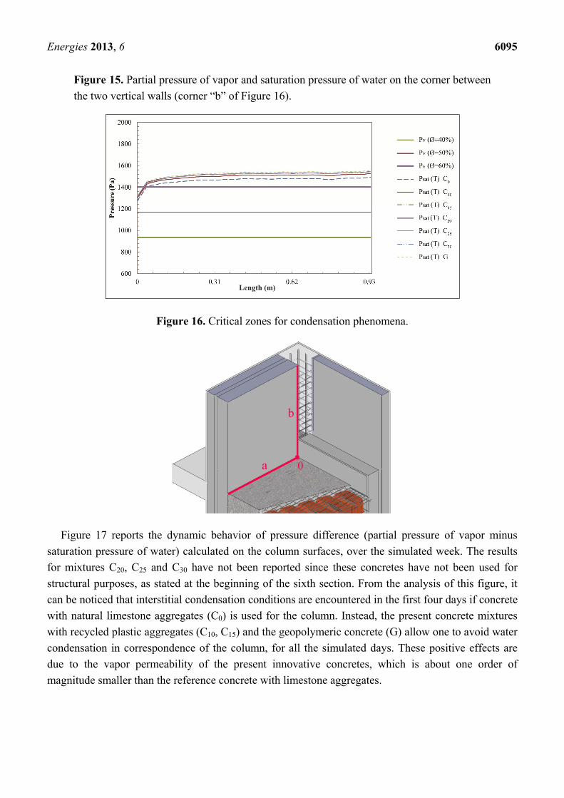
Energies 2013, 6 6095
Figure 15. Partial pressure of vapor and saturation pressure of water on the corner between
the two vertical walls (corner “b” of Figure 16).
Figure 16. Critical zones for condensation phenomena.
Figure 17 reports the dynamic behavior of pressure difference (partial pressure of vapor minus
saturation pressure of water) calculated on the column surfaces, over the simulated week. The results
for mixtures C20, C25 and C30 have not been reported since these concretes have not been used for
structural purposes, as stated at the beginning of the sixth section. From the analysis of this figure, it
can be noticed that interstitial condensation conditions are encountered in the first four days if concrete
with natural limestone aggregates (C0) is used for the column. Instead, the present concrete mixtures
with recycled plastic aggregates (C10, C15) and the geopolymeric concrete (G) allow one to avoid water
condensation in correspondence of the column, for all the simulated days. These positive effects are
due to the vapor permeability of the present innovative concretes, which is about one order of
magnitude smaller than the reference concrete with limestone aggregates.
Length (m)
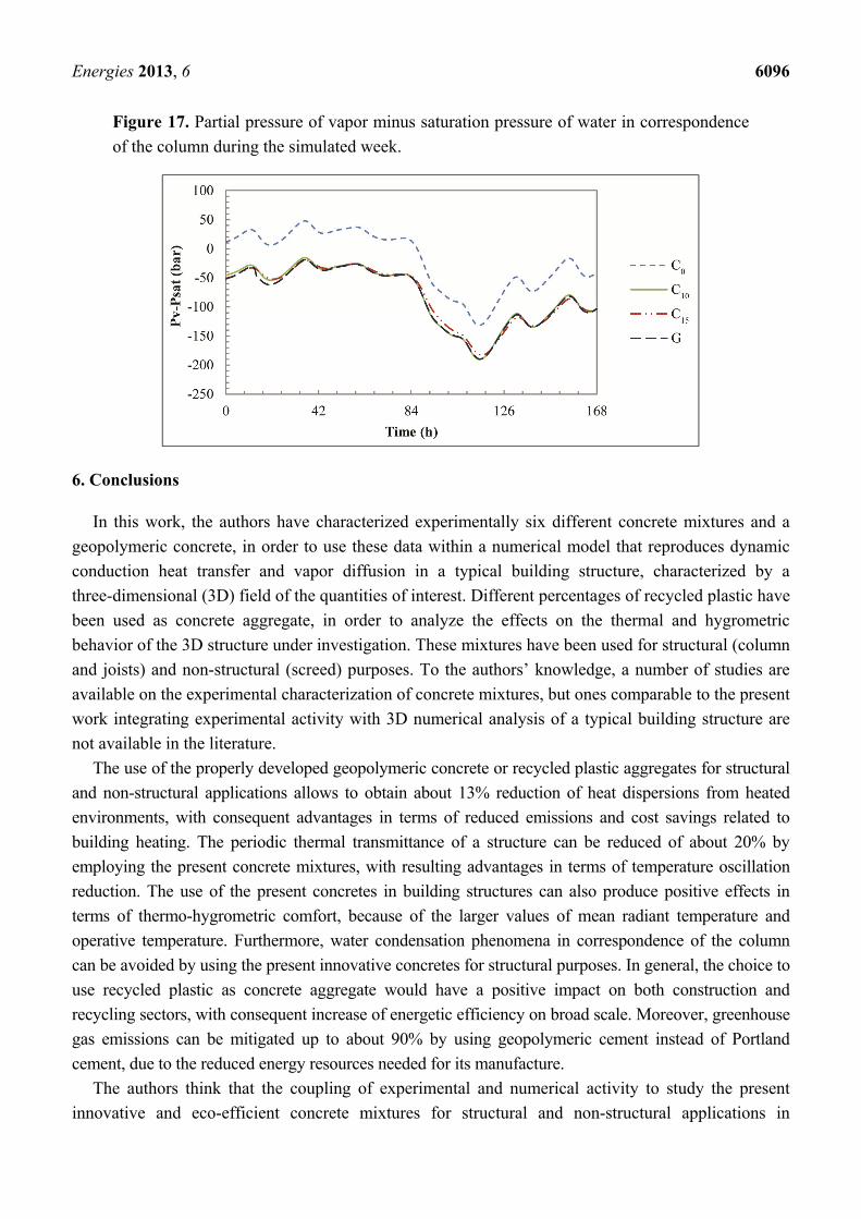
Energies 2013, 6 6096
Figure 17. Partial pressure of vapor minus saturation pressure of water in correspondence
of the column during the simulated week.
6. Conclusions
In this work, the authors have characterized experimentally six different concrete mixtures and a
geopolymeric concrete, in order to use these data within a numerical model that reproduces dynamic
conduction heat transfer and vapor diffusion in a typical building structure, characterized by a
three-dimensional (3D) field of the quantities of interest. Different percentages of recycled plastic have
been used as concrete aggregate, in order to analyze the effects on the thermal and hygrometric
behavior of the 3D structure under investigation. These mixtures have been used for structural (column
and joists) and non-structural (screed) purposes. To the authors’ knowledge, a number of studies are
available on the experimental characterization of concrete mixtures, but ones comparable to the present
work integrating experimental activity with 3D numerical analysis of a typical building structure are
not available in the literature.
The use of the properly developed geopolymeric concrete or recycled plastic aggregates for structural
and non-structural applications allows to obtain about 13% reduction of heat dispersions from heated
environments, with consequent advantages in terms of reduced emissions and cost savings related to
building heating. The periodic thermal transmittance of a structure can be reduced of about 20% by
employing the present concrete mixtures, with resulting advantages in terms of temperature oscillation
reduction. The use of the present concretes in building structures can also produce positive effects in
terms of thermo-hygrometric comfort, because of the larger values of mean radiant temperature and
operative temperature. Furthermore, water condensation phenomena in correspondence of the column
can be avoided by using the present innovative concretes for structural purposes. In general, the choice to
use recycled plastic as concrete aggregate would have a positive impact on both construction and
recycling sectors, with consequent increase of energetic efficiency on broad scale. Moreover, greenhouse
gas emissions can be mitigated up to about 90% by using geopolymeric cement instead of Portland
cement, due to the reduced energy resources needed for its manufacture.
The authors think that the coupling of experimental and numerical activity to study the present
innovative and eco-efficient concrete mixtures for structural and non-structural applications in
Energies 2013, 6 6097
buildings assumes an important role, in order to correctly characterize the transient behavior of 3D
structures involving these new materials. The present 3D simulations together with the availability of
experimental data, allowing one to obtain detailed local information in complex structures, could be
integrated with the results obtained by using lumped parameter models reproducing the behavior of
whole buildings.
Conflicts of Interest
The authors declare no conflict of interest.
References
1. Siddique, R.; Khatib, J.; Kaur, I. Use of recycled plastic in concrete: A review. Waste Manag.
2008, 28, 1835–1852.
2. Italian Government. Environmental Regulations; Legislative Decree n. 152 of 3 April 2006;
Italian Official Gazette: Rome, Italy, 2006.
3. Li, G.; Lamberti, M.; Roviello, G.; Pellecchia, C. New titanium and hafnium complexes bearing
[-NNN-] pyrrolylpyridylamido ligands as olefin polymerization catalysts. Organometallics 2012,
31, 6772–6778.
4. De Roma, A.; Yang, H.-J.; Milione, S.; Capacchione, C.; Roviello, G.; Grassi, A. Atom transfer
radical polymerization of methylmethacrylate mediated by a naphtyl-nickel(II) phosphane
complex. Inorg. Chem. Commun. 2011, 14, 542–544.
5. Roviello, A.; Buono, A.; Carella, A.; Roviello, G.; Cassinese, A.; Barra, M.; Biasucci, M.
Regioregular poly[3-(4-alkoxyphenyl)thiophene]s. J. Polym. Sci. Part A Polym. Chem. 2007, 45,
1758–1770.
6. Ferreira, L.; de Brito, J.; Saikia, N. Influence of curing conditions on the mechanical performance
of concrete containing recycled plastic aggregate. Constr. Build. Mater. 2012, 36, 196–204.
7. Colangelo, F.; Cioffi, R.; Montagnaro, F.; Santoro, L. Soluble salt removal from MSWI fly ash
and its stabilization for safer disposal and recovery as road basement material. Waste Manag.
2012, 32, 1179–1185.
8. Colangelo, F.; Cioffi, R.; Lavorgna, M.; Verdolotti, L.; De Stefano, L. Treatment and recycling of
asbestos-cement containing waste. J. Hazard. Mater. 2011, 195, 391–397.
9. Cioffi, R.; Colangelo, F.; Montagnaro, F.; Santoro, L. Manufacture of artificial aggregate using
MSWI bottom ash. Waste Manag. 2011, 31, 281–288.
10. Iucolano, F.; Liguori, B.; Caputo, D.; Colangelo, F.; Cioffi, R. Recycled plastic aggregate in mortars
composition: Effect on physical and mechanical properties. Mater. Design 2013, 52, 916–922.
11. Mun, K.J. Development and tests of lightweight aggregate using sewage sludge for nonstructural
concrete. Constr. Build. Mater. 2007, 21, 1583–1588.
12. Chang, F.-C.; Lee, M.-Y.; Lo, S.-L.; Lin, J.-D. Artificial aggregate made from waste stone sludge
and waste silt. J. Environ. Manag. 2010, 91, 2289–2294.
13. Behiry, A.E.A.E.-M. Utilization of cement treated recycled concrete aggregates as base or
subbase layer in Egypt. Ain Shams Eng. J. 2013, 4, 661–673.
Energies 2013, 6 6098
14. Ismail, S.; Ramli, M. Engineering properties of treated recycled concrete aggregate (RCA) for
structural applications. Constr. Build. Mater. 2013, 44, 464–476.
15. Mahdi, F.; Abbas, H.; Khan, A.A. Flexural, shear and bond strength of polymer concrete utilizing
recycled resin obtained from post consumer PET bottles. Constr. Build. Mater. 2013, 44, 798–811.
16. Jo, B.-W.; Park, S.-K.; Park, J.-C. Mechanical properties of polymer concrete made with recycled
PET and recycled concrete aggregates. Constr. Build. Mater. 2008, 22, 2281–2291.
17. Xiao, J.; Huang, Y.; Yang, J.; Zhang, C. Mechanical properties of confined recycled aggregate
concrete under axial compression. Constr. Build. Mater. 2012, 26, 591–603.
18. Fraternali, F.; Ciancia, V.; Chechile, R.; Rizzano, G.; Feo, L.; Incarnato, L. Experimental study of
the thermo-mechanical properties of recycled PET fiber-reinforced concrete. Compos. Struct.
2011, 93, 2368–2374.
19. Kim, S.B.; Yi, N.H.; Kim, H.Y.; Kim, J.-H.J.; Song, Y.-C. Material and structural performance
evaluation of recycled PET fiber reinforced concrete. Cem. Concr. Compos. 2010, 32, 232–240.
20. Xiao, J.; Huang, X.; Shen, L. Seismic behavior of semi-precast column with recycled aggregate
concrete. Constr. Build. Mater. 2012, 35, 988–1001.
21. Duxson, P.; Fernandez-Jimenez, A.; Provis, J.L.; Lukey, G.C.; Palomo, A.; van Deventer, J.S.J.
Geopolymer technology: The current state of art. J. Mater. Sci. 2007, 42, 2917–2933.
22. Cioffi, R.; Maffucci, L.; Santoro, L. Optimization of geopolymer synthesis by calcination and
polycondensation of a Kaolinitic residue. Resour. Conserv. Recycl. 2003, 40, 27–38.
23. Ferone, C.; Roviello, G.; Colangelo, F.; Cioffi, R.; Tarallo, O. Novel hybrid organic-geopolymer
materials. Appl. Clay Sci. 2013, 73, 42–50.
24. Colangelo, F.; Roviello, G.; Ricciotti, L.; Ferone, C.; Cioffi, R. Preparation and characterization
of new geopolymer-epoxy resin hybrid mortars. Materials 2013, 6, 2989–3006.
25. Ferone, C.; Colangelo, F.; Cioffi, R.; Montagnaro, F.; Santoro, L. Use of reservoir clay sediments
as raw materials for geopolymer binders. Adv. Appl. Ceram. 2013, 112, 184–189.
26. Xu, H.; van Deventer, J.S.J. The geopolymerisation of alumino-silicate minerals. Int. J. Miner.
Process. 2000, 59, 247–266.
27. Andini, S.; Cioffi, R.; Colangelo, F.; Grieco, T.; Montagnaro, F.; Santoro, L. Coal fly ash as raw
material for the manufacture of geopolymer-based products. Waste Manag. 2008, 28, 416–423.
28. Andini, S.; Cioffi, R.; Colangelo, F.; Ferone, C.; Montagnaro, F.; Santoro, L. Characterization of
geopolymer materials containing MSWI fly ash and coal fly ash. Adv. Sci. Technol. 2010, 69,
123–128.
29. Ferone, C.; Colangelo, F.; Cioffi, R.; Montagnaro, F.; Santoro, L. Mechanical performances of
weathered coal fly ash based geopolymer bricks. Procedia Eng. 2011, 21, 745–752.
30. Komnitsas, K.; Zaharaki, D.; Perdikatsis, V. Geopolymerisation of low calcium ferronickel slags.
J. Mater. Sci. 2007, 42, 3073–3082.
31. Duxson, P.; Lukey, G.C.; van Deventer, J.S.J. Physical evolution of Na-geopolymer derived from
metakaolin up to 1000 °C. J. Mater. Sci. 2007, 42, 3044–3054.
32. Menna, C.; Asprone, D.; Ferone, C.; Colangelo, F.; Balsamo, A.; Prota, A.; Cioffi, R.; Manfredi, G.
Use of geopolymers for composite external reinforcement of RC members. Compos. Part B 2013,
45, 1667–1676.
Energies 2013, 6 6099
33. Ferone, C.; Colangelo, F.; Roviello, G.; Cioffi, R.; Menna, C.; Asprone, D.; Balsamo, A.; Prota, A.;
Manfredi, G. Application-oriented chemical optimization of a metakaolin based geopolymer.
Materials 2013, 6, 1920–1939.
34. Palomo, A.; Blanco-Varela, M.T.; Granizo, M.L.; Puertas, F.; Vasquez, T.; Grutzeck, M.W.
Chemical stability of cementitious materials based on metakaolin. Cem. Concr. Res. 1999, 29,
997–1004.
35. Habert, G.; d’Espinose de Lacaillerie, J.B.; Roussel, N. An environmental evaluation of
geopolymer based concrete production: Reviewing current research trends. J. Cleaner Prod. 2011,
19, 1229–1238.
36. Davidovits, J. Geopolymer, Chemistry and Applications, 3rd ed.; Institute Geopolymer:
Saint-Quentin, France, 2011; pp. 10–11.
37. European Community. Directive 2002/91/EC of the European Parliament and of the Council of 16
December 2002 on the energy performance of buildings. Off. J. Eur. Commun. 2003, L1, 65–71.
38. European Union. Directive 2012/27/EU of the European Parliament and of the Council of 25
October 2012 on energy efficiency, amending Directives 2009/125/EC and 2010/30/EU and
repealing Directives 2004/8/EC and 2006/32/EC. Off. J. Eur. Union 2012, L315, 1–56.
39. European Union. Directive 2010/31/EU of the European Parliament and of the Council of 19 May
2010 on the energy performance of buildings (recast). Off. J. Eur. Union 2010, L153, 13–35.
40. Italian Government. Regulation for the Implementation of Article 4, Paragraph 1, Letters a) and
b) of Legislative Decree 19 August 2005, n. 192, Concerning the Implementation of Directive
2002/91/EC on the Energy Performance of Buildings; Presidential Decree n. 59 of 2 April 2009;
Italian Official Gazette: Rome, Italy, 2009.
41. Italian Government. Implementation of Directive 2002/91/EC on the Energy Performance of
Buildings; Legislative Decree n. 192 of 19 August 2005; Italian Official Gazette: Rome, Italy, 2005.
42. Italian Government. Corrective and Supplementary Provisions to the Legislative Decree 19 August
2005, n. 192, Implementing Directive 2002/91/EC on the Energy Performance of Buildings;
Legislative Decree n. 311 of 29 December 2006; Italian Official Gazette: Rome, Italy, 2007.
43. Arpino, F.; Massarotti, N.; Mauro, A.; Nithiarasu, P. Artificial compressibility based CBS
solutions for double diffusive natural convection in cavities. Int. J. Numer. Methods Heat Fluid
Flow 2013, 23, 205–225.
44. Arpino, F.; Carotenuto, A.; Massarotti, N.; Mauro, A. New solutions for axial flow convection in
porous and partly porous cylindrical domains. Int. J. Heat Mass Transf. 2013, 57, 155–170.
45. Carotenuto, A.; Massarotti, N.; Mauro, A. A new methodology for numerical simulation of
geothermal down-hole heat exchangers. Appl. Therm. Eng. 2012, 48, 225–236.
46. Arpino, F.; Massarotti, N.; Mauro, A. Efficient three-dimensional FEM based algorithm for the
solution of convection in partly porous domains. Int. J. Heat Mass Transf. 2011, 54, 4495–4506.
47. Mauro, A.; Arpino, F.; Massarotti, N. Three-dimensional simulation of heat and mass transport
phenomena in planar SOFCs. Int. J. Hydrog. Energy 2011, 36, 10288–10301.
48. Mauro, A.; Arpino, F.; Massarotti, N.; Nithiarasu, P. A novel single domain approach for numerical
modelling solid oxide fuel cells. Int. J. Numer. Methods Heat Fluid Flow 2010, 20, 587–612.
Energies 2013, 6 6100
49. European Committee for Standardization (CEN). Part 1: Composition, Specifications and
Conformity Criteria for Common Cements. In Cement; European Standard, EN 197-1:2011;
CEN: Brussels, Belgium, 2011.
50. European Committee for Standardization (CEN). Part 1: Specification, Performance, Production and
Conformity. In Concrete; European Standard, UNI EN 206-1:2006; CEN: Brussels, Belgium, 2006.
51. Fernandez-Jimenez, A.; Palomo, A. Nanostructure/Microstructure of Fly Ash Geopolymers. In
Geopolymers: Structure, Processing, Properties and Industrial Applications; Provis, J.L.,
van Deventer, J.S.J., Eds.; CRC Press/Taylor and Francis: Boca Raton, FL, USA, 2009; pp. 89–117.
52. European Committee for Standardization (CEN). Part 19: Determination of Water Vapour
Permeability of Hardened Rendering and Plastering Mortars. In Methods of Test for Mortar for
Masonry; European Standard, UNI EN 1015-19:2008; CEN: Brussels, Belgium, 2008.
53. Zienkiewicz, O.C.; Taylor, R.L.; Nithiarasu, P. The Finite Element Method for Fluid Dynamics,
6th ed.; Elsevier Butterworth-Heinemann: Oxford, UK, 2005.
54. Lewis, R.W.; Nithiarasu, P.; Seetharamu, K.N. Fundamentals of the Finite Element Method for
Heat and Fluid Flow; John Wiley & Sons: Chichester, England, UK, 2004.
55. International Organization for Standardization (ISO). Hygrothermal Performance of Building
Components and Building Elements—Internal Surface Temperature to Avoid Critical Surface
Humidity and Interstitial Condensation—Calculation Methods; International Standard, UNI EN
ISO 13788:2003; ISO: Geneva, Switzerland, 2003.
56. International Organization for Standardization (ISO). Thermal Bridges in Building
Construction—Heat Flows and Surface Temperatures—Detailed Calculation; International
Standard, UNI EN ISO 10211:2008; ISO: Geneva, Switzerland, 2008.
57. Ente Nazionale Italiano di Unificazione (UNI). Materiali da Costruzione—Conduttività Termica e
Permeabilità al Vapore (in Italian); Italian Standard, UNI 10351:1994; UNI: Milan, Italy, 1994.
58. European Committee for Standardization (CEN). Building Materials and Products—Hygrothermal
Properties—Tabulated Design Values; European Standard, UNI EN 12524:2001; CEN: Brussels,
Belgium, 2001.
59. International Organization for Standardization (ISO). Building Materials and
Products—Hygrothermal Properties—Tabulated Design Values and Procedures for Determining
Declared and Design Thermal Values; International Standard, UNI EN ISO 10456:2008;
ISO: Geneva, Switzerland, 2008.
60. International Organization for Standardization (ISO). Building Components and Building
Elements—Thermal Resistance and Thermal Transmittance—Calculation Method; International
Standard, UNI EN ISO 6946:2008; ISO: Geneva, Switzerland, 2008.
61. International Organization for Standardization (ISO). Thermal Performance of Building
Components—Dynamic Thermal Characteristics—Calculation Methods; International Standard,
UNI EN ISO 13786:2007; ISO: Geneva, Switzerland, 2007.
62. International Organization for Standardization (ISO). Part 4: Hourly Data for Assessing the Annual
Energy Use for Heating and Cooling. In Hygrothermal Performance of Buildings—Calculation and
Presentation of Climatic Data; International Standard, UNI EN ISO 15927-4:2005; ISO: Geneva,
Switzerland, 2005.
Energies 2013, 6 6101
63. International Organization for Standardization (ISO). Ergonomics of the Thermal
Environment—Analytical Determination and Interpretation of Thermal Comfort Using
Calculation of the PMV and PPD Indices and Local Thermal Comfort Criteria; International
Standard, ISO 7730:2005; ISO: Geneva, Switzerland, 2005.
64. International Organization for Standardization (ISO). Ergonomics of the Thermal
Environment—Instruments for Measuring Physical Quantities; International Standard, UNI EN
ISO 7726:2002; ISO: Geneva, Switzerland, 2002.
65. American Society of Heating, Refrigerating and Air-Conditioning Engineers, Inc. (ASHRAE).
Thermal Comfort. In ASHRAE Handbook—Fundamentals; ASHRAE: Atlanta, GA, USA,
2009; Chapter 9.
© 2013 by the authors; licensee MDPI, Basel, Switzerland. This article is an open access article
distributed under the terms and conditions of the Creative Commons Attribution license
(http://creativecommons.org/licenses/by/3.0/).