Embed Size (px)
Citation preview
1
Experiment 2 Introduction to TI C2000 Microcontroller, Code Composer
Studio (CCS) and Matlab Graphic User Interface (GUI)
2.1 Objectives
The objective of this experiment is to familiarize the students with the basics of TI C2000 microcontroller, Matlab Real Time Workshop, Code Composer Studio, and Matlab Graphic User Interface (GUI). Students learn how to develop a Simulink program to generate a PWM signal with adjustable duty cycle on one of the I/O pins of the microcontroller.
2.2 Matlab/Simulink Environment
The concepts of rapid prototyping and digital control techniques in power electronics in the developed laboratory are realized based on using the TI C2000 micro-controller in conjunction with the Matlab/Simulink software based on an integrated development environment. As depicted in the following flowachats, Matlab/Simulink environment is used for the design, optimization, and off-line simulations of the models and power electronic circuits. The Real Time Workshop converts the Simulink model to C programming code. Subsequently, the executable C code is automatically compiled to the assembly language for the TI C2000 micro-controller, assembled, link-edited, and downloaded. Finally, Matlab Graphical User Interface (GUI) is used to run, tune, and monitor the running process.
The ultimate goal of the program we develop in this laboratory is for digital control of a buck and/or boost converter using Matlab/Simulink based on a to-be-developed setup shown in the following diagram. In this lab session, we focus on the generation of a PWM signal with controllable duty cycle on one of the I/O ports of the microcontroller. The duty cycle of the PWM signal will be adjusted online in Matlab/Simulink environment. The PWM signal will be interfaced to the designed buck and/or boost converter in the upcoming lab sessions.
2
Requirements:
1) Software: Matlab/Simulink and Code Composer Studio 2) Hardware: C2000 Microcontroller(TMS320F28035) and Blackhawk USB2000 emulator
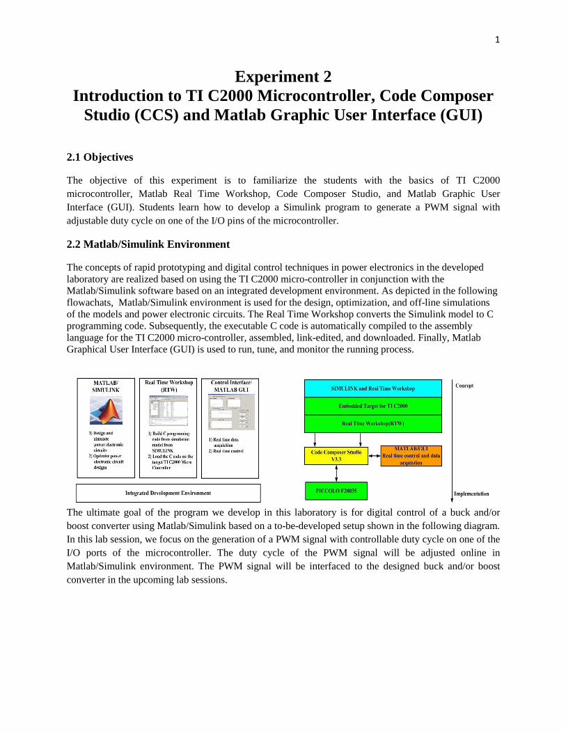
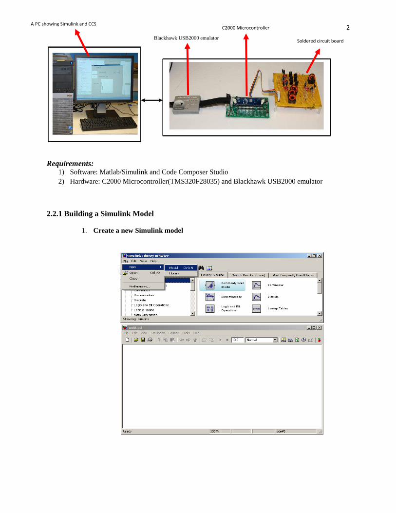
2.2.1 Building a Simulink Model 1. Create a new Simulink model
Blackhawk USB2000 emulator
C2000 Microcontroller A PC showing Simulink and CCS
Soldered circuit board
3
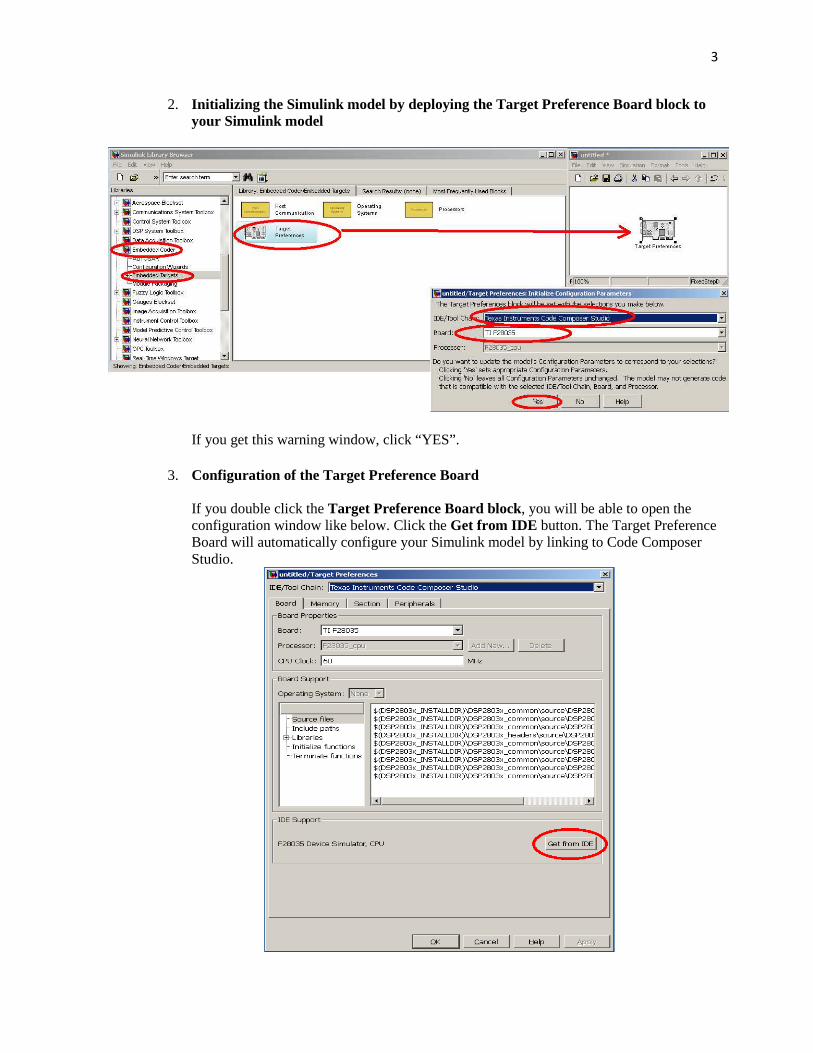
2. Initializing the Simulink model by deploying the Target Preference Board block to your Simulink model
If you get this warning window, click “YES”.
3. Configuration of the Target Preference Board If you double click the Target Preference Board block, you will be able to open the configuration window like below. Click the Get from IDE button. The Target Preference Board will automatically configure your Simulink model by linking to Code Composer Studio.
4
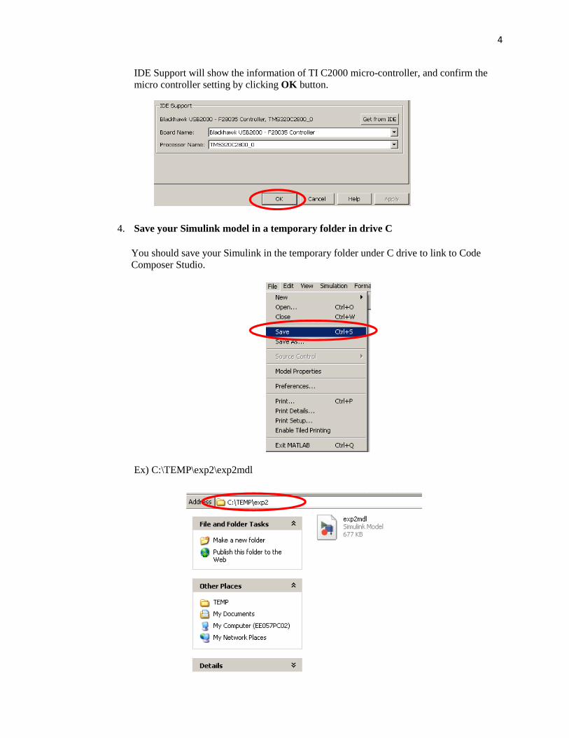
IDE Support will show the information of TI C2000 micro-controller, and confirm the micro controller setting by clicking OK button.
4. Save your Simulink model in a temporary folder in drive C You should save your Simulink in the temporary folder under C drive to link to Code Composer Studio.
Ex) C:\TEMP\exp2\exp2mdl

5
5. Designing a power electronics control module of PWM Add the “From RTDX” block and "ePWM” block in your Simulink model.
6
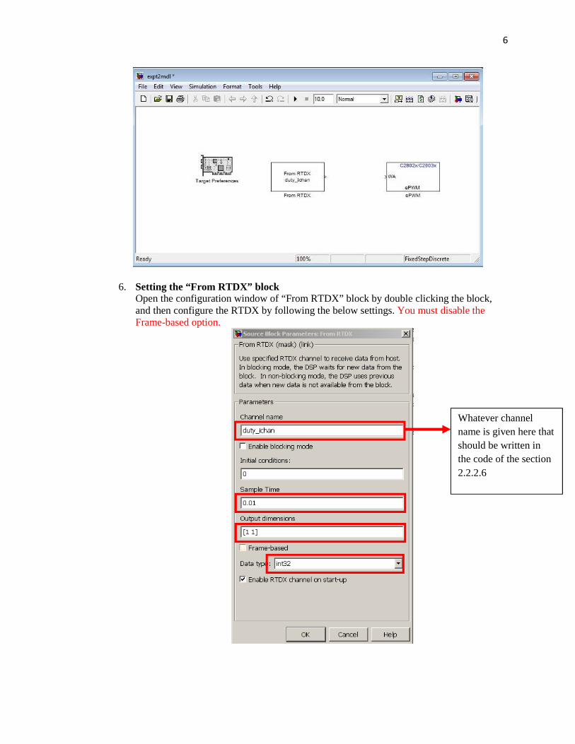
6. Setting the “From RTDX” block Open the configuration window of “From RTDX” block by double clicking the block, and then configure the RTDX by following the below settings. You must disable the Frame-based option.
Whatever channel name is given here that should be written in the code of the section 2.2.2.6
7
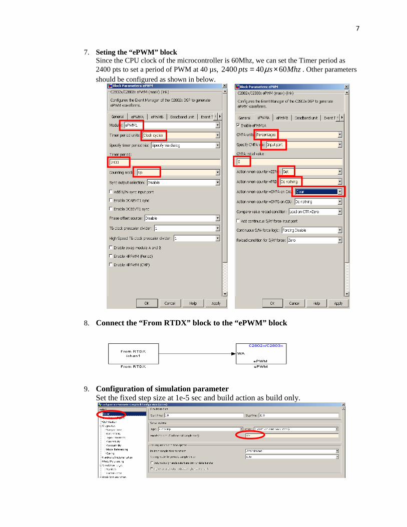
7. Seting the “ePWM” block Since the CPU clock of the microcontroller is 60Mhz, we can set the Timer period as 2400 pts to set a period of PWM at 40 µs, 2400 40 60pts s Mhzµ= × . Other parameters should be configured as shown in below.
8. Connect the “From RTDX” block to the “ePWM” block
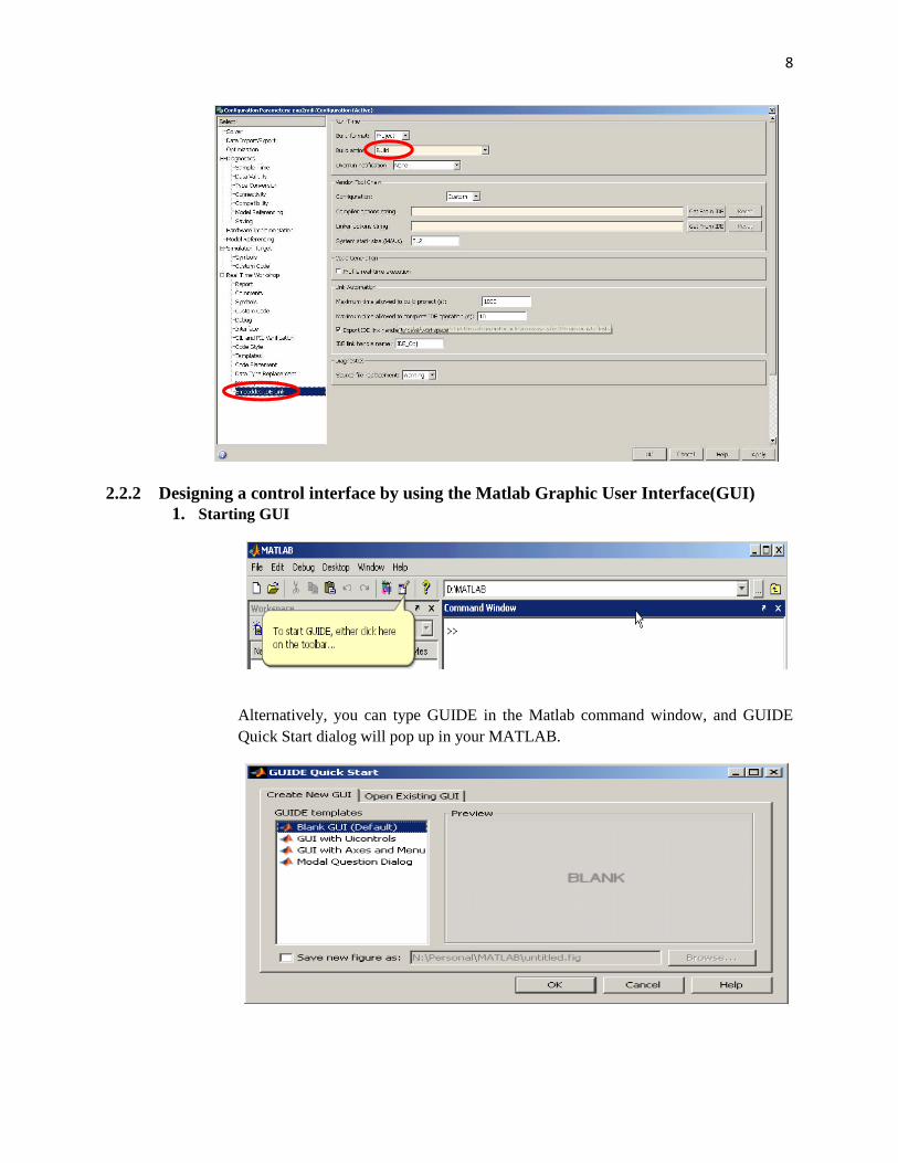
9. Configuration of simulation parameter
Set the fixed step size at 1e-5 sec and build action as build only.
8
2.2.2 Designing a control interface by using the Matlab Graphic User Interface(GUI) 1. Starting GUI
Alternatively, you can type GUIDE in the Matlab command window, and GUIDE Quick Start dialog will pop up in your MATLAB.
9
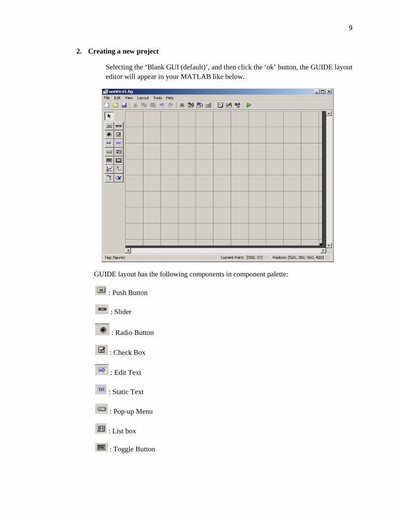
2. Creating a new project
Selecting the ‘Blank GUI (default)’, and then click the ‘ok’ button, the GUIDE layout editor will appear in your MATLAB like below.
GUIDE layout has the following components in component palette:
: Push Button
: Slider
: Radio Button
: Check Box
: Edit Text
: Static Text
: Pop-up Menu
: List box
: Toggle Button
10
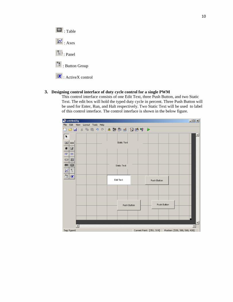
: Table
: Axes
: Panel
: Button Group
: ActiveX control
3. Designing control interface of duty cycle control for a single PWM
This control interface consists of one Edit Text, three Push Button, and two Static Text. The edit box will hold the typed duty cycle in percent. Three Push Button will be used for Enter, Run, and Halt respectively. Two Static Text will be used to label of this control interface. The control interface is shown in the below figure.
11
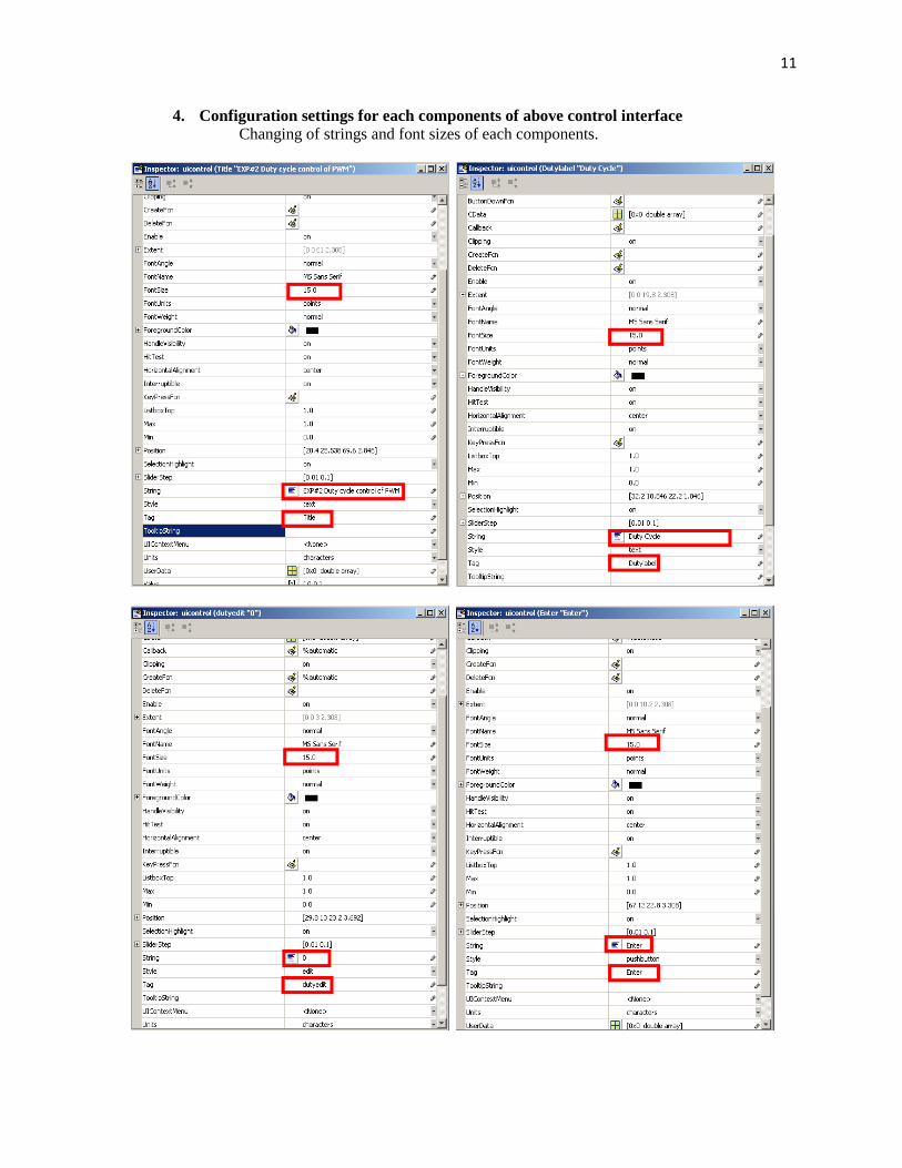
4. Configuration settings for each components of above control interface Changing of strings and font sizes of each components.

12
The configured control interface is depicted in the below figure.
13
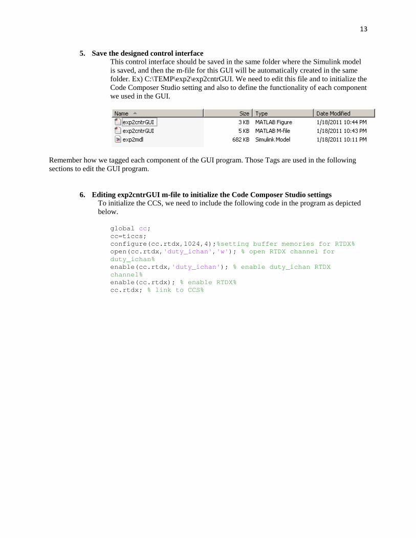
5. Save the designed control interface This control interface should be saved in the same folder where the Simulink model is saved, and then the m-file for this GUI will be automatically created in the same folder. Ex) C:\TEMP\exp2\exp2cntrGUI. We need to edit this file and to initialize the Code Composer Studio setting and also to define the functionality of each component we used in the GUI.
Remember how we tagged each component of the GUI program. Those Tags are used in the following sections to edit the GUI program.
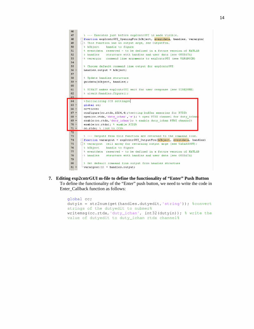
6. Editing exp2cntrGUI m-file to initialize the Code Composer Studio settings To initialize the CCS, we need to include the following code in the program as depicted below.
global cc ; cc=ticcs; configure(cc.rtdx,1024,4); %setting buffer memories for RTDX% open(cc.rtdx, 'duty_ichan' , 'w' ); % open RTDX channel for duty_ichan% enable(cc.rtdx, 'duty_ichan' ); % enable duty_ichan RTDX channel% enable(cc.rtdx); % enable RTDX% cc.rtdx; % link to CCS%
14
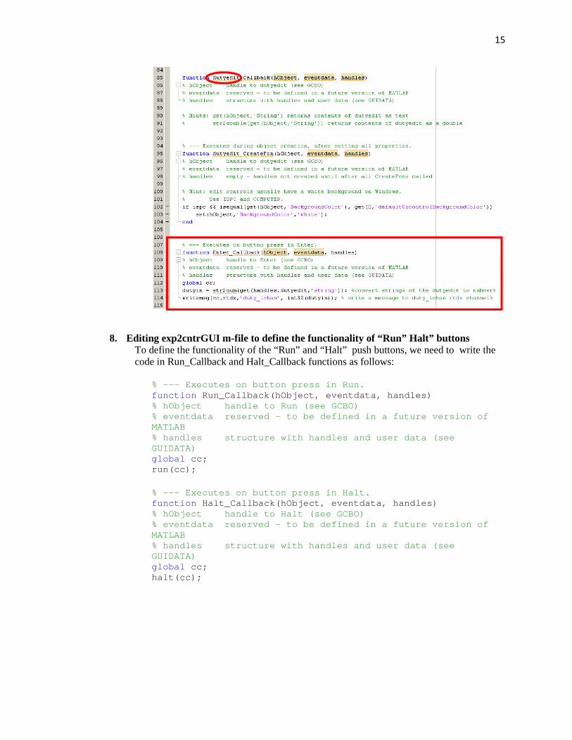
7. Editing exp2cntrGUI m-file to define the functionality of “Enter” Push Button To define the functionality of the “Enter” push button, we need to write the code in Enter_Callback function as follows:
global cc; dutyin = str2num(get(handles.dutyedit, 'string' )); %convert strings of the dutyedit to nubmer% writemsg(cc.rtdx, 'duty_ichan' , int32(dutyin)); % write the value of dutyedit to duty_ichan rtdx channel%
15
8. Editing exp2cntrGUI m-file to define the functionality of “Run” Halt” buttons To define the functionality of the “Run” and “Halt” push buttons, we need to write the code in Run_Callback and Halt_Callback functions as follows:
% --- Executes on button press in Run. function Run_Callback(hObject, eventdata, handles) % hObject handle to Run (see GCBO) % eventdata reserved - to be defined in a future v ersion of MATLAB % handles structure with handles and user data ( see GUIDATA) global cc; run(cc);
% --- Executes on button press in Halt. function Halt_Callback(hObject, eventdata, handles) % hObject handle to Halt (see GCBO) % eventdata reserved - to be defined in a future v ersion of MATLAB % handles structure with handles and user data ( see GUIDATA) global cc; halt(cc);

16
2.2.3 Implementation
1. Turn on the TI C2000 micro-controller
You must turn on the TI C2000 micro-controller by selecting the USB side of toggle switch.
2. Check the connection between the Matlab and TI C2000 micro-controller
Type “ticcs” in the Matlab command window to check the connection between the TI C2000 micro-controller and Matlab. If the connection is established, you will get the following message.
3. Build C code language from simulation model
Users can build the simulation model by clicking the build button in the simulation toolbar.
17
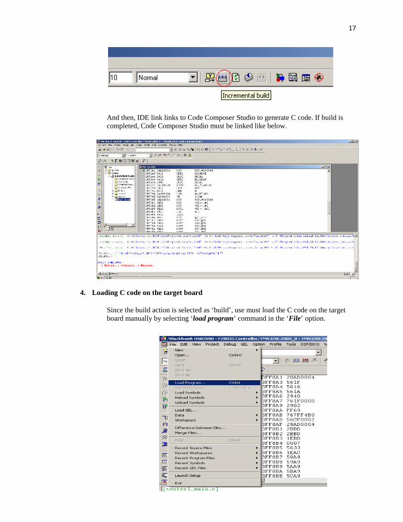
And then, IDE link links to Code Composer Studio to generate C code. If build is completed, Code Composer Studio must be linked like below.
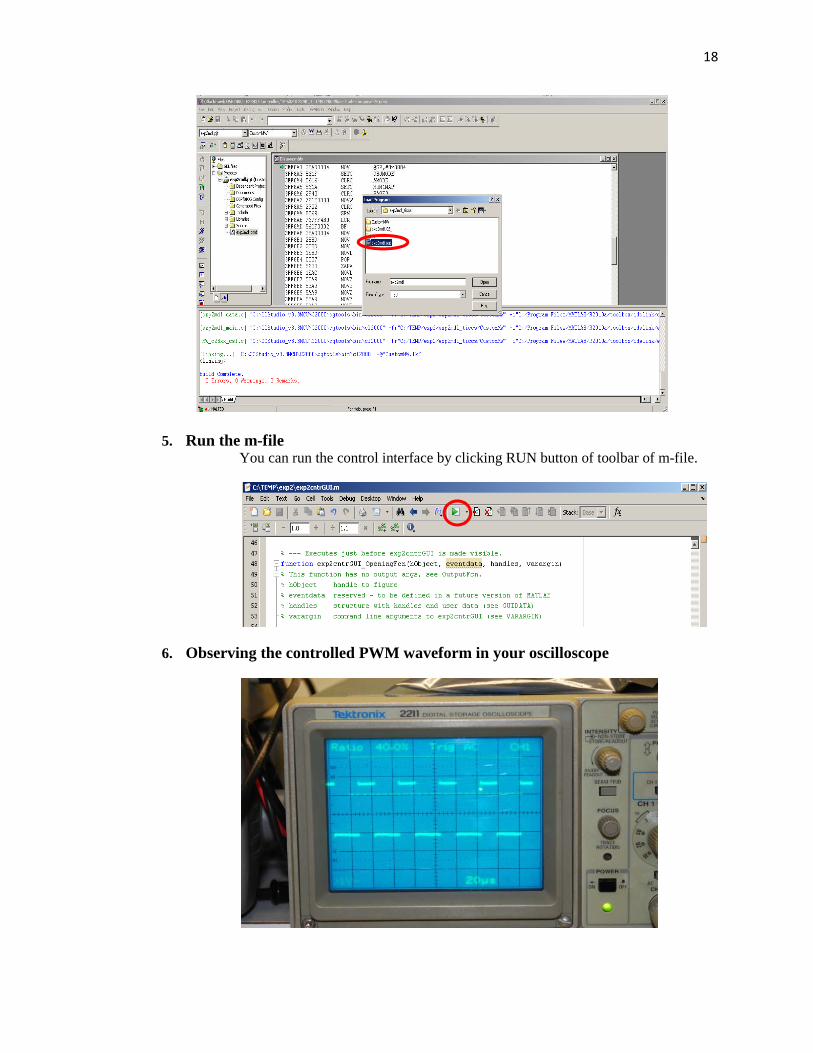
4. Loading C code on the target board
Since the build action is selected as ‘build’, use must load the C code on the target board manually by selecting ‘load program’ command in the ‘File’ option.
18
5. Run the m-file You can run the control interface by clicking RUN button of toolbar of m-file.
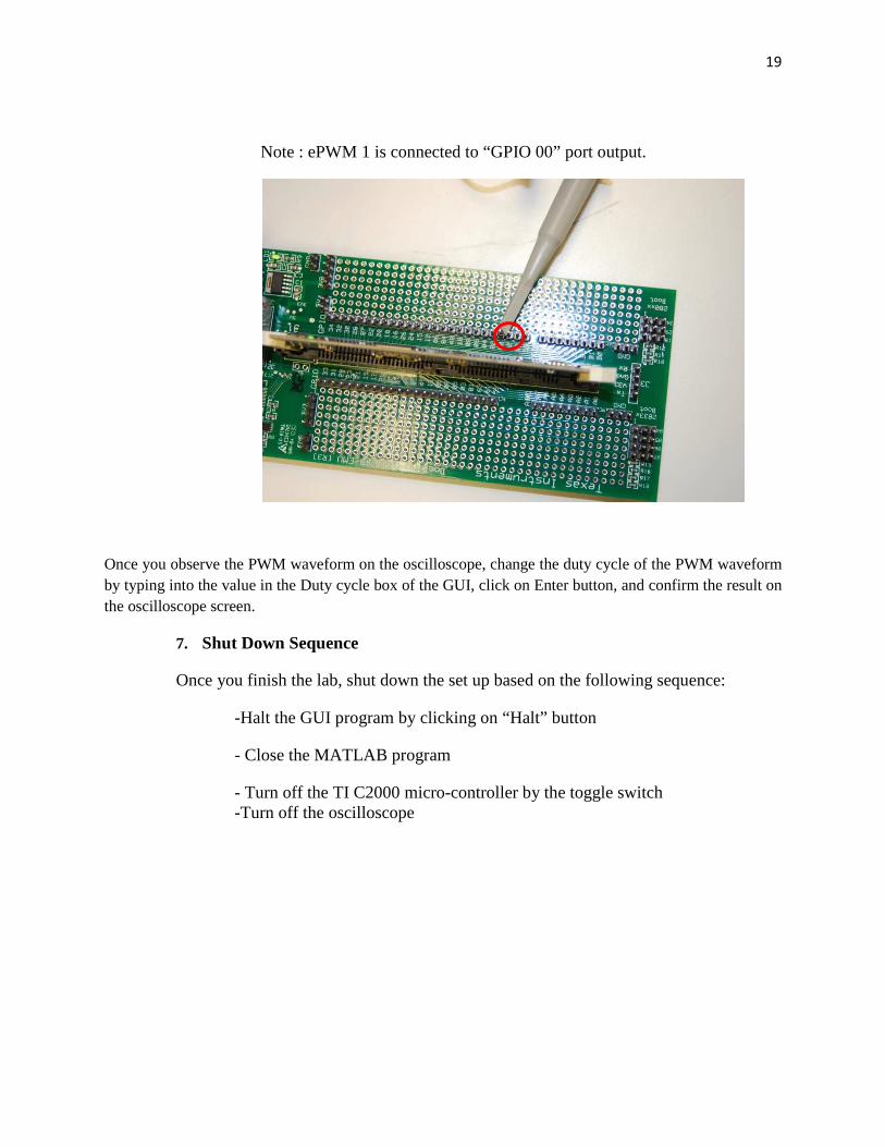
6. Observing the controlled PWM waveform in your oscilloscope
19
Note : ePWM 1 is connected to “GPIO 00” port output.
Once you observe the PWM waveform on the oscilloscope, change the duty cycle of the PWM waveform by typing into the value in the Duty cycle box of the GUI, click on Enter button, and confirm the result on the oscilloscope screen.
7. Shut Down Sequence
Once you finish the lab, shut down the set up based on the following sequence:
-Halt the GUI program by clicking on “Halt” button
- Close the MATLAB program
- Turn off the TI C2000 micro-controller by the toggle switch -Turn off the oscilloscope