Embed Size (px)
Citation preview
LDO
TM4C123xDRV8833
Stepper motor driver
GPIO
3.3 V
4.5 V
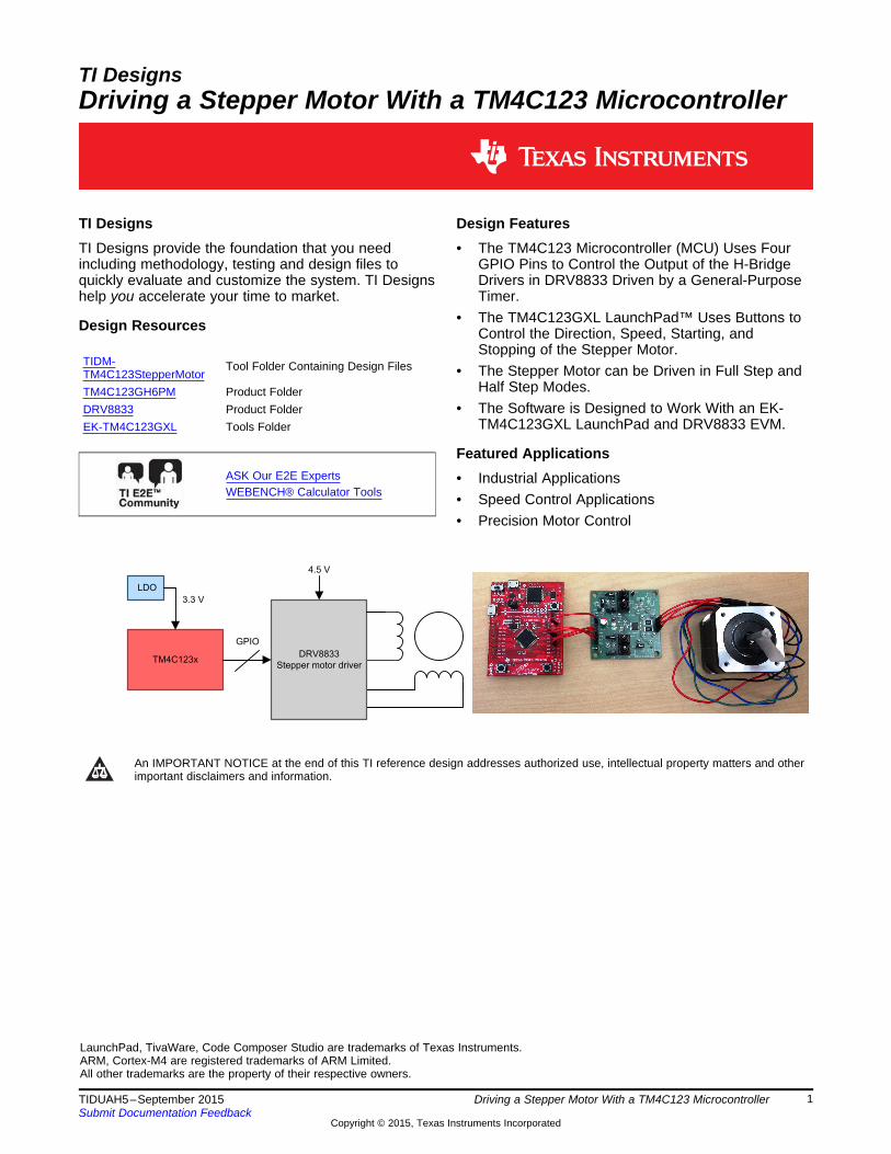
TI DesignsDriving a Stepper Motor With a TM4C123 Microcontroller
TI Designs Design FeaturesTI Designs provide the foundation that you need • The TM4C123 Microcontroller (MCU) Uses Fourincluding methodology, testing and design files to GPIO Pins to Control the Output of the H-Bridgequickly evaluate and customize the system. TI Designs Drivers in DRV8833 Driven by a General-Purposehelp you accelerate your time to market. Timer.
• The TM4C123GXL LaunchPad™ Uses Buttons toDesign Resources Control the Direction, Speed, Starting, andStopping of the Stepper Motor.
TIDM- Tool Folder Containing Design Files • The Stepper Motor can be Driven in Full Step andTM4C123StepperMotorHalf Step Modes.TM4C123GH6PM Product Folder
DRV8833 Product Folder • The Software is Designed to Work With an EK-TM4C123GXL LaunchPad and DRV8833 EVM.EK-TM4C123GXL Tools Folder
Featured ApplicationsASK Our E2E Experts • Industrial ApplicationsWEBENCH® Calculator Tools • Speed Control Applications
• Precision Motor Control
An IMPORTANT NOTICE at the end of this TI reference design addresses authorized use, intellectual property matters and otherimportant disclaimers and information.
LaunchPad, TivaWare, Code Composer Studio are trademarks of Texas Instruments.ARM, Cortex-M4 are registered trademarks of ARM Limited.All other trademarks are the property of their respective owners.
1TIDUAH5–September 2015 Driving a Stepper Motor With a TM4C123 MicrocontrollerSubmit Documentation Feedback
Copyright © 2015, Texas Instruments Incorporated
System Description www.ti.com
1 System DescriptionThis system example shows how to control a stepper motor with the TM4C123 high-performance MCUand DRV8833 motor driver. The direction, speed, starting, and stopping of stepper motor can becontrolled by buttons on the EK-TM4C123GXL LaunchPad. This example uses a general-purpose timer tocontrol 4 GPIO pins to generate the PWM signals for driving the motor.
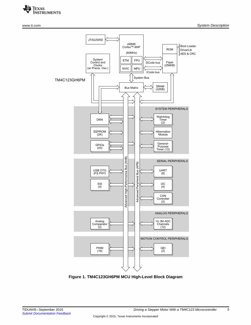
1.1 TM4C123GH6PM MCUThe TM4C123GH6PM microcontroller is targeted for industrial applications including the following: remotemonitoring, electronic point-of-sale machines, test equipment, measurement equipment, networkappliances, switches, factory automation, HVAC, building control, gaming equipment, motion control,transportation, and security.
The TM4C123GH6PM MCU has up to 43 GPIOs with programmable control for GPIO interrupts, padconfiguration, and pin muxing. The MCU is integrated with six 32-bit general-purpose timers (up to twelve16-bit), eight UARTs, four synchronous serial interface (SSI) modules, four inter-integrated circuit (I2C)modules, two 12-bit analog-to-digital converters (ADC) with 12 analog input channels and a sample rate ofone million samples per second, eight pulse width modulation (PWM) generator blocks, and twoquadrature encoder interface (QEI) modules. The universal serial bus (USB) controller supports the USBOTG/Host/Device modes. The ARM® PrimeCell 32-channel configurable μDMA controller is alsointegrated to provide a method to offload data transfer tasks from the Cortex-M4® processor and to moreefficiently use the processor and the bus bandwidth.
See Figure 1 for a high-level overview of the TM4C123GH6PM MCU.
2 Driving a Stepper Motor With a TM4C123 Microcontroller TIDUAH5–September 2015Submit Documentation Feedback
Copyright © 2015, Texas Instruments Incorporated
ARM®Cortex™-M4F
(80MHz)
NVIC MPU
FPUETMFlash
(256KB)
Boot Loader
DriverLib
AES & CRC
ROM
DCode bus
ICode bus
JTAG/SWD
SystemControl and
Clocks(w/ Precis. Osc.)
Bus Matrix
System Bus
SRAM(32KB)
SYSTEM PERIPHERALS
WatchdogTimer
(2)DMA
HibernationModule
EEPROM(2K)
General-Purpose
Timer (12)
GPIOs(43)
SERIAL PERIPHERALS
UART(8)
USB OTG(FS PHY)
I2C(4)
SSI(4)
CANController
(2)
ANALOG PERIPHERALS
12- Bit ADCChannels
(12)
AnalogComparator
(2)
MOTION CONTROL PERIPHERALS
QEI(2)
PWM(16)
Ad
va
nce
dP
erip
he
ralB
us
(AP
B)
Ad
va
nce
dH
igh
-Pe
rfo
rma
nce
Bu
s(A
HB
)
TM4C123GH6PM
www.ti.com System Description
Figure 1. TM4C123GH6PM MCU High-Level Block Diagram
3TIDUAH5–September 2015 Driving a Stepper Motor With a TM4C123 MicrocontrollerSubmit Documentation Feedback
Copyright © 2015, Texas Instruments Incorporated
DRV8833
Stepper or brushed DC motor driver
Controller
PWM
nSLEEP
nFAULT
M1.5 A
+
-
+ -
1.5 A
2.7 V to 10.8 V
System Description www.ti.com
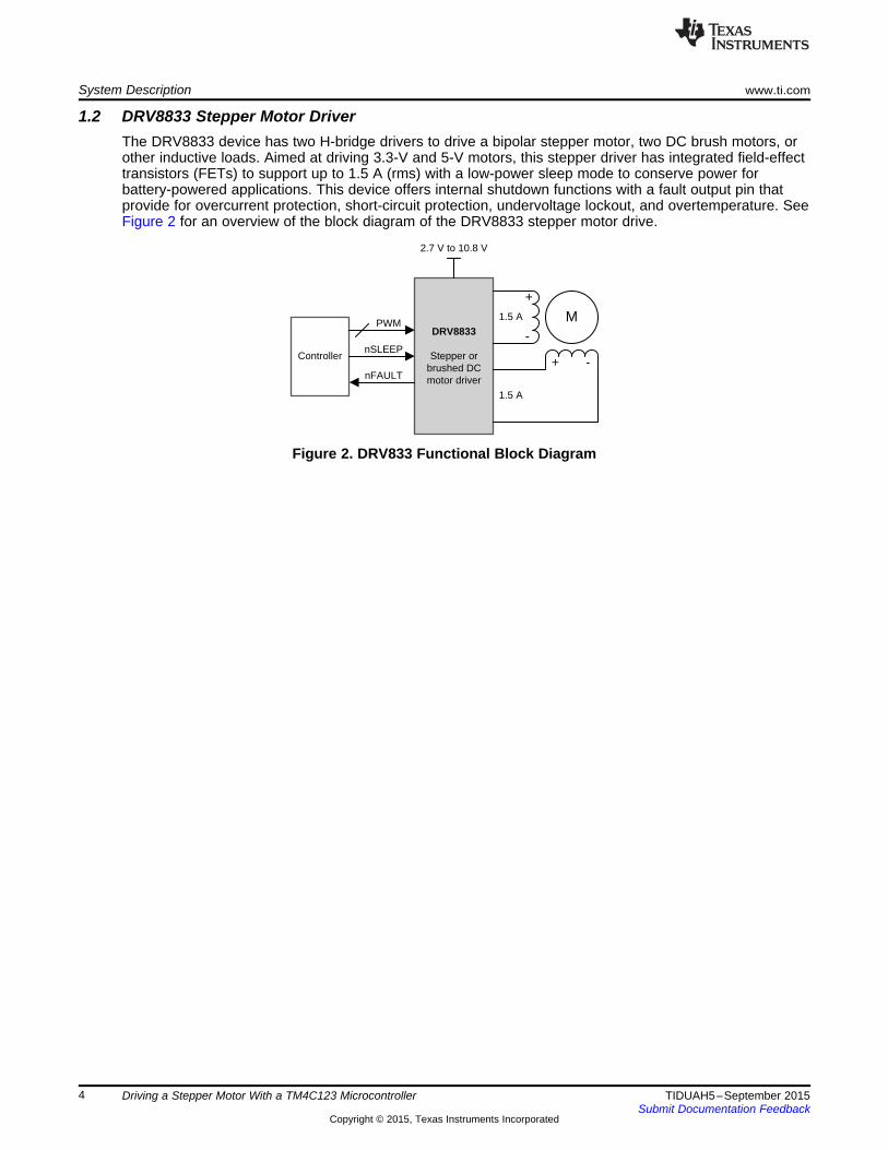
1.2 DRV8833 Stepper Motor DriverThe DRV8833 device has two H-bridge drivers to drive a bipolar stepper motor, two DC brush motors, orother inductive loads. Aimed at driving 3.3-V and 5-V motors, this stepper driver has integrated field-effecttransistors (FETs) to support up to 1.5 A (rms) with a low-power sleep mode to conserve power forbattery-powered applications. This device offers internal shutdown functions with a fault output pin thatprovide for overcurrent protection, short-circuit protection, undervoltage lockout, and overtemperature. SeeFigure 2 for an overview of the block diagram of the DRV8833 stepper motor drive.
Figure 2. DRV833 Functional Block Diagram
4 Driving a Stepper Motor With a TM4C123 Microcontroller TIDUAH5–September 2015Submit Documentation Feedback
Copyright © 2015, Texas Instruments Incorporated
www.ti.com Getting Started Hardware
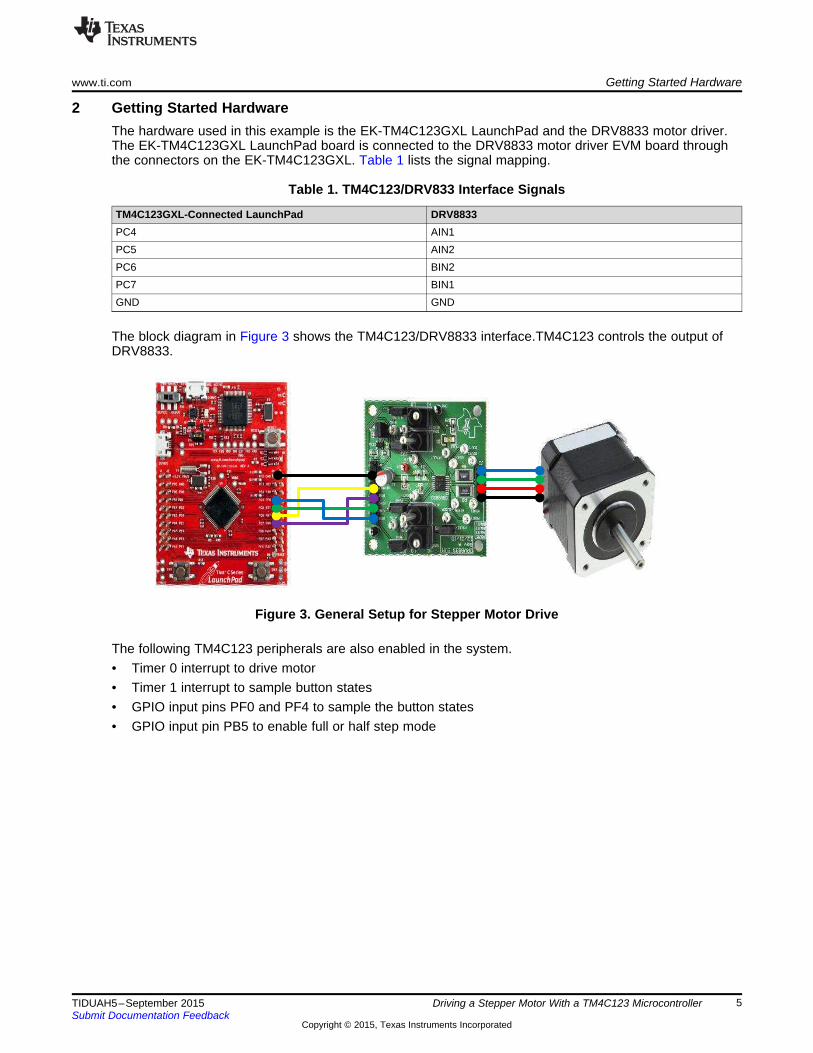
2 Getting Started HardwareThe hardware used in this example is the EK-TM4C123GXL LaunchPad and the DRV8833 motor driver.The EK-TM4C123GXL LaunchPad board is connected to the DRV8833 motor driver EVM board throughthe connectors on the EK-TM4C123GXL. Table 1 lists the signal mapping.
Table 1. TM4C123/DRV833 Interface Signals
TM4C123GXL-Connected LaunchPad DRV8833PC4 AIN1PC5 AIN2PC6 BIN2PC7 BIN1GND GND
The block diagram in Figure 3 shows the TM4C123/DRV8833 interface.TM4C123 controls the output ofDRV8833.
Figure 3. General Setup for Stepper Motor Drive
The following TM4C123 peripherals are also enabled in the system.• Timer 0 interrupt to drive motor• Timer 1 interrupt to sample button states• GPIO input pins PF0 and PF4 to sample the button states• GPIO input pin PB5 to enable full or half step mode
5TIDUAH5–September 2015 Driving a Stepper Motor With a TM4C123 MicrocontrollerSubmit Documentation Feedback
Copyright © 2015, Texas Instruments Incorporated
Timer 0
Processing
Timer 1
GPIOs
Full or
half steps
Buttons
Motor
Getting Started Software www.ti.com
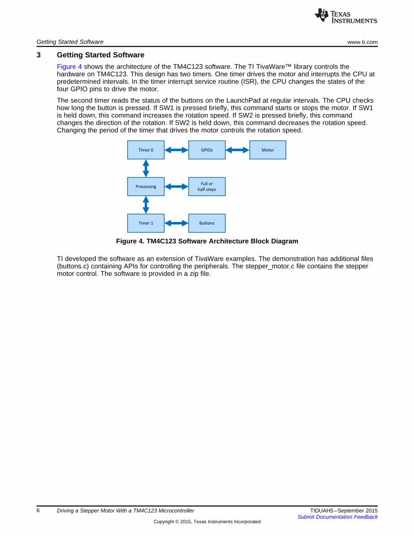
3 Getting Started SoftwareFigure 4 shows the architecture of the TM4C123 software. The TI TivaWare™ library controls thehardware on TM4C123. This design has two timers. One timer drives the motor and interrupts the CPU atpredetermined intervals. In the timer interrupt service routine (ISR), the CPU changes the states of thefour GPIO pins to drive the motor.
The second timer reads the status of the buttons on the LaunchPad at regular intervals. The CPU checkshow long the button is pressed. If SW1 is pressed briefly, this command starts or stops the motor. If SW1is held down, this command increases the rotation speed. If SW2 is pressed briefly, this commandchanges the direction of the rotation. If SW2 is held down, this command decreases the rotation speed.Changing the period of the timer that drives the motor controls the rotation speed.
Figure 4. TM4C123 Software Architecture Block Diagram
TI developed the software as an extension of TivaWare examples. The demonstration has additional files(buttons.c) containing APIs for controlling the peripherals. The stepper_motor.c file contains the steppermotor control. The software is provided in a zip file.
6 Driving a Stepper Motor With a TM4C123 Microcontroller TIDUAH5–September 2015Submit Documentation Feedback
Copyright © 2015, Texas Instruments Incorporated
www.ti.com Installing the Demo
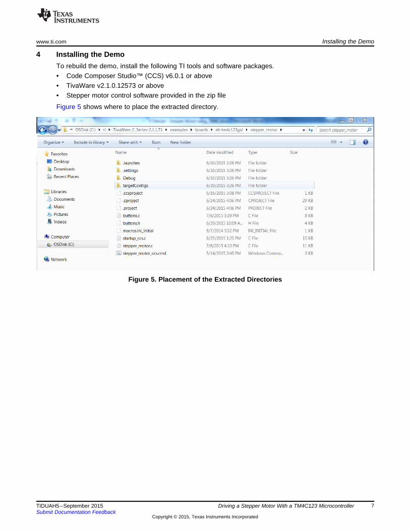
4 Installing the DemoTo rebuild the demo, install the following TI tools and software packages.• Code Composer Studio™ (CCS) v6.0.1 or above• TivaWare v2.1.0.12573 or above• Stepper motor control software provided in the zip file
Figure 5 shows where to place the extracted directory.
Figure 5. Placement of the Extracted Directories
7TIDUAH5–September 2015 Driving a Stepper Motor With a TM4C123 MicrocontrollerSubmit Documentation Feedback
Copyright © 2015, Texas Instruments Incorporated
Installing the Demo www.ti.com
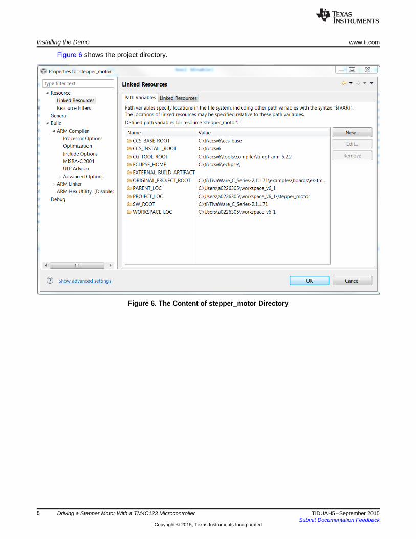
Figure 6 shows the project directory.
Figure 6. The Content of stepper_motor Directory
8 Driving a Stepper Motor With a TM4C123 Microcontroller TIDUAH5–September 2015Submit Documentation Feedback
Copyright © 2015, Texas Instruments Incorporated
www.ti.com Installing the Demo
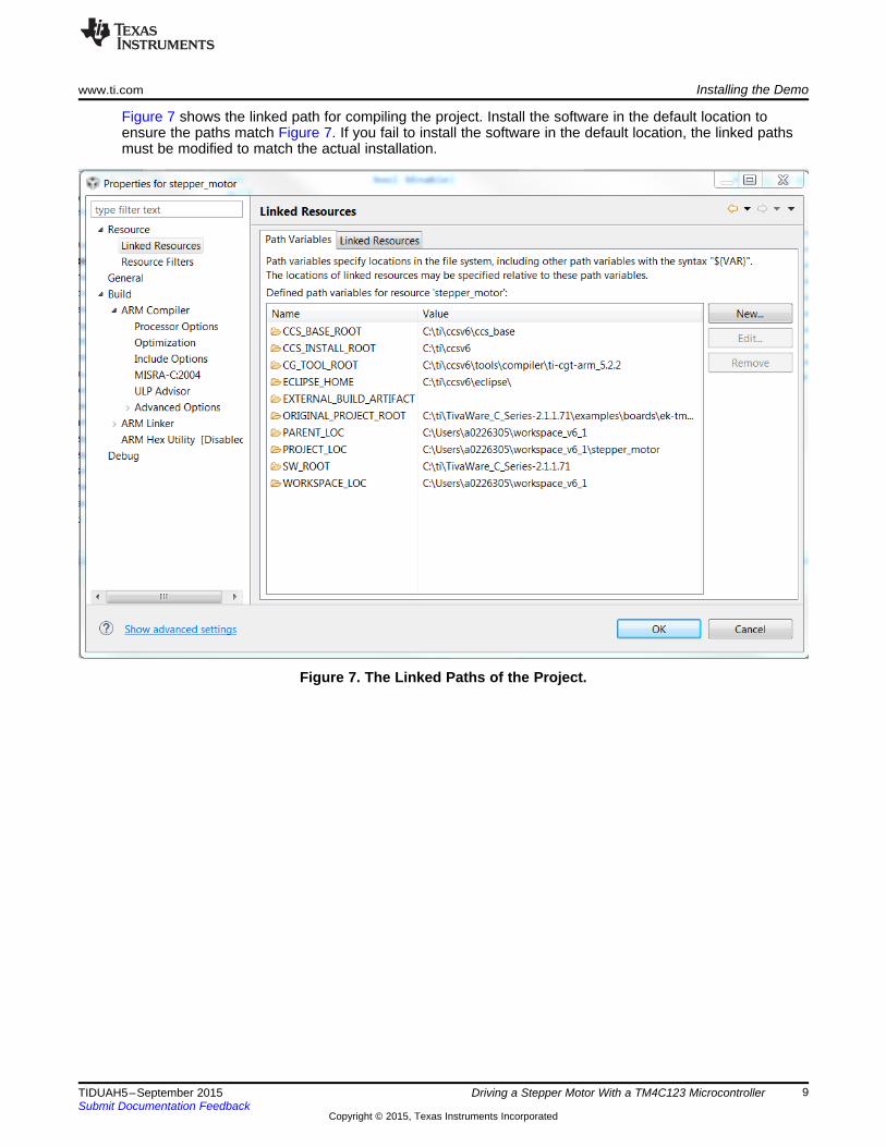
Figure 7 shows the linked path for compiling the project. Install the software in the default location toensure the paths match Figure 7. If you fail to install the software in the default location, the linked pathsmust be modified to match the actual installation.
Figure 7. The Linked Paths of the Project.
9TIDUAH5–September 2015 Driving a Stepper Motor With a TM4C123 MicrocontrollerSubmit Documentation Feedback
Copyright © 2015, Texas Instruments Incorporated
Executing the Demonstration www.ti.com
5 Executing the DemonstrationThe LaunchPad buttons control the state and speed of the motor. Pressing button SW1 once turns themotor on or off. Pressing and holding SW1 increases the speed of the motor until SW1 is released or untilthe motor reaches the maximum speed. Pressing button SW2 changes the direction of the motor.Pressing and holding SW2 decreases the speed of the motor until SW2 is released or until minimumspeed is reached.
The CPU loading increases with higher rotation speed because the timer interrupts are generated morefrequently at a higher rotation speed. This is a fraction of CPU capability. The real minimum and maximumrotation speed is determined by the characteristics of the motor. The developers chose the minimum andmaximum rotation speed limit to demonstrate the change in the rotation speed.
6 ResourcesTo download the software files and resource files for this reference design, visit the following website:http://www.ti.com/tool/TIDM-TM4C123StepperMotor.
7 References
1. TivaWare for C Series2. EK-TM4C1293GXL LaunchPad3. DRV8833C Stepper Motor Driver
10 Driving a Stepper Motor With a TM4C123 Microcontroller TIDUAH5–September 2015Submit Documentation Feedback
Copyright © 2015, Texas Instruments Incorporated
IMPORTANT NOTICE FOR TI REFERENCE DESIGNS
Texas Instruments Incorporated ("TI") reference designs are solely intended to assist designers (“Buyers”) who are developing systems thatincorporate TI semiconductor products (also referred to herein as “components”). Buyer understands and agrees that Buyer remainsresponsible for using its independent analysis, evaluation and judgment in designing Buyer’s systems and products.TI reference designs have been created using standard laboratory conditions and engineering practices. TI has not conducted anytesting other than that specifically described in the published documentation for a particular reference design. TI may makecorrections, enhancements, improvements and other changes to its reference designs.Buyers are authorized to use TI reference designs with the TI component(s) identified in each particular reference design and to modify thereference design in the development of their end products. HOWEVER, NO OTHER LICENSE, EXPRESS OR IMPLIED, BY ESTOPPELOR OTHERWISE TO ANY OTHER TI INTELLECTUAL PROPERTY RIGHT, AND NO LICENSE TO ANY THIRD PARTY TECHNOLOGYOR INTELLECTUAL PROPERTY RIGHT, IS GRANTED HEREIN, including but not limited to any patent right, copyright, mask work right,or other intellectual property right relating to any combination, machine, or process in which TI components or services are used.Information published by TI regarding third-party products or services does not constitute a license to use such products or services, or awarranty or endorsement thereof. Use of such information may require a license from a third party under the patents or other intellectualproperty of the third party, or a license from TI under the patents or other intellectual property of TI.TI REFERENCE DESIGNS ARE PROVIDED "AS IS". TI MAKES NO WARRANTIES OR REPRESENTATIONS WITH REGARD TO THEREFERENCE DESIGNS OR USE OF THE REFERENCE DESIGNS, EXPRESS, IMPLIED OR STATUTORY, INCLUDING ACCURACY ORCOMPLETENESS. TI DISCLAIMS ANY WARRANTY OF TITLE AND ANY IMPLIED WARRANTIES OF MERCHANTABILITY, FITNESSFOR A PARTICULAR PURPOSE, QUIET ENJOYMENT, QUIET POSSESSION, AND NON-INFRINGEMENT OF ANY THIRD PARTYINTELLECTUAL PROPERTY RIGHTS WITH REGARD TO TI REFERENCE DESIGNS OR USE THEREOF. TI SHALL NOT BE LIABLEFOR AND SHALL NOT DEFEND OR INDEMNIFY BUYERS AGAINST ANY THIRD PARTY INFRINGEMENT CLAIM THAT RELATES TOOR IS BASED ON A COMBINATION OF COMPONENTS PROVIDED IN A TI REFERENCE DESIGN. IN NO EVENT SHALL TI BELIABLE FOR ANY ACTUAL, SPECIAL, INCIDENTAL, CONSEQUENTIAL OR INDIRECT DAMAGES, HOWEVER CAUSED, ON ANYTHEORY OF LIABILITY AND WHETHER OR NOT TI HAS BEEN ADVISED OF THE POSSIBILITY OF SUCH DAMAGES, ARISING INANY WAY OUT OF TI REFERENCE DESIGNS OR BUYER’S USE OF TI REFERENCE DESIGNS.TI reserves the right to make corrections, enhancements, improvements and other changes to its semiconductor products and services perJESD46, latest issue, and to discontinue any product or service per JESD48, latest issue. Buyers should obtain the latest relevantinformation before placing orders and should verify that such information is current and complete. All semiconductor products are soldsubject to TI’s terms and conditions of sale supplied at the time of order acknowledgment.TI warrants performance of its components to the specifications applicable at the time of sale, in accordance with the warranty in TI’s termsand conditions of sale of semiconductor products. Testing and other quality control techniques for TI components are used to the extent TIdeems necessary to support this warranty. Except where mandated by applicable law, testing of all parameters of each component is notnecessarily performed.TI assumes no liability for applications assistance or the design of Buyers’ products. Buyers are responsible for their products andapplications using TI components. To minimize the risks associated with Buyers’ products and applications, Buyers should provideadequate design and operating safeguards.Reproduction of significant portions of TI information in TI data books, data sheets or reference designs is permissible only if reproduction iswithout alteration and is accompanied by all associated warranties, conditions, limitations, and notices. TI is not responsible or liable forsuch altered documentation. Information of third parties may be subject to additional restrictions.Buyer acknowledges and agrees that it is solely responsible for compliance with all legal, regulatory and safety-related requirementsconcerning its products, and any use of TI components in its applications, notwithstanding any applications-related information or supportthat may be provided by TI. Buyer represents and agrees that it has all the necessary expertise to create and implement safeguards thatanticipate dangerous failures, monitor failures and their consequences, lessen the likelihood of dangerous failures and take appropriateremedial actions. Buyer will fully indemnify TI and its representatives against any damages arising out of the use of any TI components inBuyer’s safety-critical applications.In some cases, TI components may be promoted specifically to facilitate safety-related applications. With such components, TI’s goal is tohelp enable customers to design and create their own end-product solutions that meet applicable functional safety standards andrequirements. Nonetheless, such components are subject to these terms.No TI components are authorized for use in FDA Class III (or similar life-critical medical equipment) unless authorized officers of the partieshave executed an agreement specifically governing such use.Only those TI components that TI has specifically designated as military grade or “enhanced plastic” are designed and intended for use inmilitary/aerospace applications or environments. Buyer acknowledges and agrees that any military or aerospace use of TI components thathave not been so designated is solely at Buyer's risk, and Buyer is solely responsible for compliance with all legal and regulatoryrequirements in connection with such use.TI has specifically designated certain components as meeting ISO/TS16949 requirements, mainly for automotive use. In any case of use ofnon-designated products, TI will not be responsible for any failure to meet ISO/TS16949.IMPORTANT NOTICE
Mailing Address: Texas Instruments, Post Office Box 655303, Dallas, Texas 75265Copyright © 2015, Texas Instruments Incorporated