Embed Size (px)
Citation preview

GIC System Model Procedure Manual ERCOT Public
GIC System Model Procedure Manual
Version 12
RO S A ppro ve d: J un e 9, 20 16
ERCOT June 9, 2016
1
GIC System Model Procedure Manual ERCOT Public
2ERCOT June 9, 2016
Document Revisions
Date Version Description Author(s)
06/09/2016 Version 1 First EditionDraft PGDTF
06/28/2016 Version 2 Revised Draft PGDTF
RO S A ppro ve d: J un e 9, 20 16
GIC System Model Procedure Manual ERCOT Public
3ERCOT June 9, 2016
Contents 1. Purpose.............................................................................................................................. 4 2. Definitions and Acronyms................................................................................................... 4 3. Data Requirements for GIC System Model ...................................................................... 5
3.1. General................................................................................................................. 5 3.1.1. Software ................................................................................................. 5 3.1.2. GIC System Model................................................................................ 5
3.2. Substation Data.................................................................................................... 6 3.3. Transformer Data Including Generator Step-Up (GSU)....................................... 7 3.4. Bus Fixed Shunt (Shunt Reactor) Data.............................................................. 11 3.5. Transmission Line Models............................................................. ....................12 3.6. User Earth Model Data....................................................................................... 12
4. Modeling Refinements.......................................................................................................14 4.1. Maintenance of GIC System Model (IMM, Workbook and EPPRE) .................. 14
Appendix A – Station Number Range.................................................................................. 15 Appendix B – Data Entry Templates.................................................................................... 17
RO S A ppro ve d: J un e 9, 20 16
DRAFT Planning Geomagnetic Disturbance Task Force (PGDTF) Procedure Manual ERCOT Public
1. Purpose
The purpose of the GIC System Model Procedure Manual is to facilitate and guide the development and maintenance of the Geomagnetically Induced Current (GIC) system System m odel M odel which will be used by ERCOT to calculate per phase GICs and Mvar losses for each modeled transformer.
On a periodic basis, the Planning Geomagnetic Disturbance Task Force (PGDTF) will review this manual for needed updates. Any member of the PGDTF can submit proposed changes. The PGDTF will strive to develop consensus on the proposed changes. If consensus cannot be achieved, alternative proposed changes will be developed with an explanation of the alternatives and will be provided to the Reliability and Operations Subcommittee (ROS) for its consideration. A red-lined version and a final version will be provided to the ROS for its review and approval.
2. Definitions and Acronyms
In the event of a conflict between any definitions or acronyms included in this manual and any definitions or acronyms established in the ERCOT Protocols, the definitions and acronyms established in the ERCOT Protocols take precedence.
2.1. Definitions
GMD Geomagnetic Disturbance (GMD) is a geomagnetic storm caused by Coronal Mass Ejection (CME), which are associated with enormous changes and disturbances in the coronal magnetic field of the Sun. If CMEs contact the Earth, they create a disruption in the Earth’s magnetic field. GMDs have the potential to impact the power grid. This is due to GMD-related changes in the Earth’s magnetic field inducing quasi-dc electric fields in the earth (with frequencies usually much below 1 Hz) with the electric field’s magnitude and direction GMD event dependent. These electric fields in-turn cause Geomagnetically Induced Currents (GICs) in the high voltage grid. These quasi-dc currents can then cause half cycle saturation in the power transformers, resulting in increased transformer reactive power losses.
IDEV A script file recognized by the PSS®E application used for transporting and applying network model changes in PSS®E.
GIC System Model Direct current resistance model of the transmission system used to calculate geomagnetically induced currents and reactive power losses.

2.2. Acronyms
RO S A ppro ve d: J un e 9, 20 16
ERCOT 4June 9, 2016

ERCOT June 9, 20165
dc Direct CurrentEPPRE ERCOT-prescribed process applicable to Resource Entities that
defines the method of data submittal for Resource Entities.IMM Information Model ManagerPAR Phase Angle RegulatorPGDTF Planning Geomagnetic Disturbance Task Force PGDT F Planning Geom agnetic Task Force USGS United States Geological Survey
3. Data Requirements for GIC System Model
3.1. General
3.1.1. Software
PSS®E will be used by ERCOT to build the GIC system System modelsModels (Model). Models will not be created in any other format by ERCOT. The PSS®E version used will follow the version used by the Steady State Working Group with the exception of using PSS®E 34 for initial model Model build.
3.1.2. GIC System Model – General
ERCOT shall provide a workbook to TSPs for the submission of data for the GIC system System m odelM odel. TSPs shall provide the GIC system System m odel M odel data to ERCOT using the provided workbook as shown in Appendix B by the schedule published by the PGDTF.
For the 200 kV system and above, actual data should be used for the GIC system System m odelM odel. Typical data based upon actual data o r d a t a c o n v e r t e d f r o m S S W G b a s e c a s e d a t a can be used if actual data is not available.
For the 69 kV and 138 kV systems, actual data should may be used for the GIC system System model Model to the extent possible. Typical data based upon actual data can be used if actual data is not available. Default data as specified by this Procedure Manual o r d a t a c o n v e r t e d f r o m S S W G b a s e c a s e d a t a can be used if actual or typical data is not reasonably available.
The PGDTF will select the latest update to the SSWG base cases, updated if required to reflect known and significant changes, to be used as the starting base cases for the GIC system System m odel M odel as listed below.
• The System Peak case will be represented by the SSWG three year out Summer Peak case.
• The Off-peak case will be represented by the three year out SSWG MIN case.
ERCOT June 9, 20166
RO S A ppro ve d: J un e 9, 20 16
ERCOT June 9, 20166
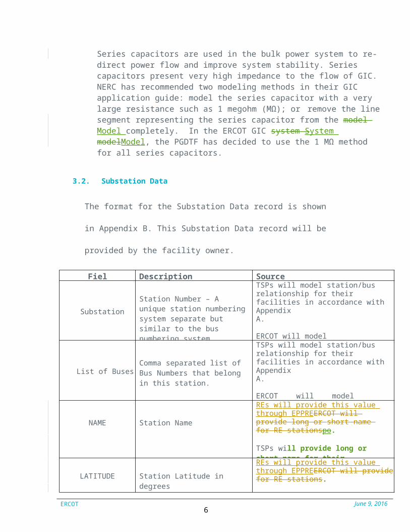
Series capacitors are used in the bulk power system to re-direct power flow and improve system stability. Series capacitors present very high impedance to the flow of GIC. NERC has recommended two modeling methods in their GIC application guide: model the series capacitor with a very large resistance such as 1 megohm (MΩ); or remove the line segment representing the series capacitor from the m odel M odel completely. In the ERCOT GIC system System modelModel, the PGDTF has decided to use the 1 MΩ method for all series capacitors.
3.2. Substation Data
The format for the Substation Data record is shown in Appendix B.
This Substation Data record will be provided by the facility owner.
Field Description Source
Substation
Station Number – A unique station numbering system separate but similar to the bus numbering system.
TSPs will model station/bus relationship for their facilities in accordance withAppendix A.
ERCOT will model station/bus relationship for Resource Entity (RE) facilities in
List of BusesComma separated list of Bus Numbers that belong in this station.
TSPs will model station/bus relationship for their facilities in accordance withAppendix A.
ERCOT will model station/bus relationship for RE facilities in accordance with Appendix A.
NAME Station Name
REs wil l provide this value through EPPREERCO T wil l provide long or short name f or RE st at ionspo.
TSPs will provide long or short name for their stations.
LATITUDE Station Latitude in degrees
REs wil l provide this value through EPPREERCO T wil l provide f or RE st at ions.
TSPs will provide this data for their
LONGITUDE Station Longitude in degrees
REs wil l provide this value through EPPREERCO T wil l provide f or RE st at ions.
TSPs will provide this data for their
ERCOT June 9, 20167
RG
Substation dc grounding resistance (ohms) for stationswith high side wye grounded transformers and shunt reactors. If RG<=0.0 or RG>=99.0, it is assumed that substation is ungrounded. RG = 0.1 ohm by default.
REs wil l provide this value through EPPREERCO T wil l provide f or RE st at ions.
TSPs will provide this data for their stations.
EARTH MODEL (v34)
Name of the Earth Model ERCOT will provide this data for RE stations, and TSPs will provide this data for their stations. EARTH MODEL is USGS standard earth conduct ivit y models avail able at USG S’s websit e:http : // g e o m a g .us g s. g o v /conduct i v i t y / .
RO S A ppro ve d: J un e 9, 20 16

ERCOT June 9, 20167
(v34) conduct ivit y models avail able at USG S’s websit ehttp : // g e o m a g .us g s. g o v /conduct i v i t y / .
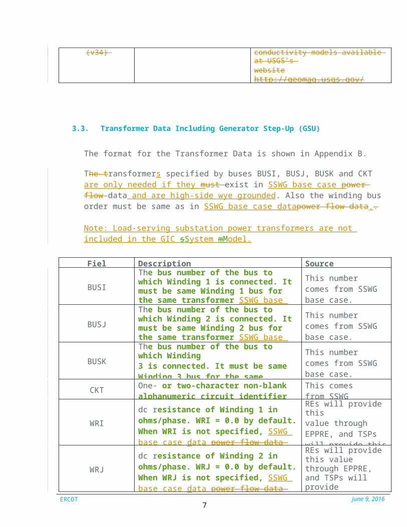
3.3. Transformer Data Including Generator Step-Up (GSU)
The format for the Transformer Data is shown in Appendix B.
The transformers specified by buses BUSI, BUSJ, BUSK and CKT are only needed if they must exist in SSWG base case powe r f low data and are high-side wye grounded. Also the winding bus order must be same as in SSWG base case datapower f low data..
Note: Load-serving substation power transformers are not included in the GIC sSystem mModel.
Field Description Source
BUSI
The bus number of the bus to which Winding 1 is connected. It must be same Winding 1 bus for the same transformer SSWG base case datapower f low
This number comes from SSWG base case.
BUSJ
The bus number of the bus to which Winding 2 is connected. It must be same Winding 2 bus for the same transformer SSWG base case datapower f low data. No
This number comes from SSWG base case.
BUSK
The bus number of the bus to which Winding3 is connected. It must be same Winding 3 bus for the same transformer SSWG base case data
This number comes from SSWG base case.
CKT One- or two-character non-blank alphanumeric circuit identifier
This comes from SSWG base case.
WRI
dc resistance of Winding 1 in ohms/phase. WRI = 0.0 by default. When WRI is not specified, SSWG base case data power f low data resistance is used to determine WRI.
REs will provide thisvalue through EPPRE, and TSPs will provide this value through the workbook.
WRJ
dc resistance of Winding 2 in ohms/phase. WRJ = 0.0 by default. When WRJ is not specified, SSWG base case data power f low data resistance is used to determine WRJ.
REs will provide this value through EPPRE, and TSPs will providethis value through theworkbook.
ERCOT June 9, 20168
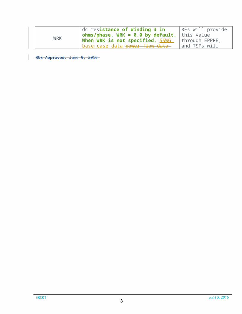
WRK
dc resistance of Winding 3 in ohms/phase. WRK = 0.0 by default. When WRK is not specified, SSWG base case data power f low data resistance is used to determine WRK.
REs will provide this value through EPPRE, and TSPs will provide this value through the
RO S A ppro ve d: J un e 9, 20 16
ERCOT June 9, 20168
workbook.
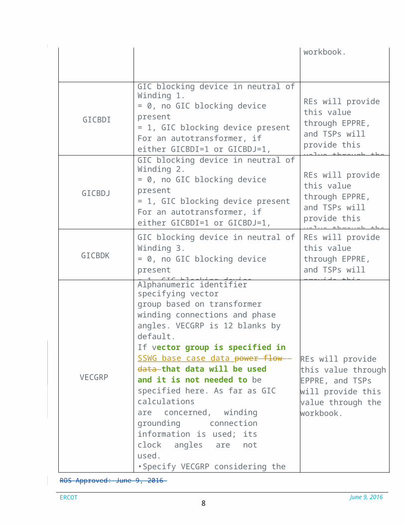
GICBDI
GIC blocking device in neutral of Winding 1.= 0, no GIC blocking device present= 1, GIC blocking device presentFor an autotransformer, if either GICBDI=1 or GICBDJ=1, thatautotransformer is treated as it has GIC blocking device present.GICBDI = 0 by default.
REs will provide this value through EPPRE, and TSPs will provide this value through the workbook.
GICBDJ
GIC blocking device in neutral of Winding 2.= 0, no GIC blocking device present= 1, GIC blocking device presentFor an autotransformer, if either GICBDI=1 or GICBDJ=1, thatautotransformer is treated as it has GIC blocking device present.GICBDJ = 0 by default.
REs will provide this value through EPPRE, and TSPs will provide this value through the workbook.
GICBDK
GIC blocking device in neutral of Winding 3.= 0, no GIC blocking device present= 1, GIC blocking device present GICBDK = 0 for two winding transformers GICBDK = 0 by default.
REs will provide this value through EPPRE, and TSPs will provide this value through the workbook.
VECGRP
Alphanumeric identifier specifying vectorgroup based on transformerwinding connections and phase angles. VECGRP is 12 blanks by default.If vector group is specified in SSWG base case data power f low data that data will be usedand it is not needed to be specified here. As far as GIC calculationsare concerned, winding grounding connection information is used; its clock angles are not used.• Specify VECGRP considering the winding order I, J, K defined on this record.• For autotransformers, bus with lower base bus voltage is treated ascommon winding bus.• For three winding autotransformers, windings on bus I and bus J form autotransformer.
REs will provide this value through EPPRE, and TSPs will provide this value through the workbook.
RO S A ppro ve d: J un e 9, 20 16
ERCOT June 9, 20169
• First Symbol: for High Voltage: Always capital letters. D=Delta, Y=Wye, Z=Interconnected star, N=Neutral
• Second Symbol: for Low voltage: Always Small letters. d=Delta, y=wye, z=Interconnected star, n=Neutral.
• Third Symbol: Phase displacement expressed as the clock hour number (1,6,11)
• 0 =0° that the LV phasor is in phase with the HV phasor
• 1 =30° lagging (LV lags HV with 30°) because rotation is anti-clockwise.
• 11 = 330° lagging or 30° leading (LV leads HV with 30°)
• 5 = 150° lagging (LV lags HV with 150°)
• 6 = 180° lagging (LV lags HV with 180°)
Steps for finding vector group in PSS®E:
1. Open PSS®E.2. Open a case.3. Select Branch tab and then select
“2- Winding” or “3-Winding tab”.4. Right Click on the transformer that
you would like to add vector group to.
5. Select “Network Data Record” from pop-up.
6. Click the “…” button next to the Vector Group blank.
7. Fill in transformer data in the pop-up screen and click “OK”.
8. PSS®E will fill in the vector group blank with correct notation.
CORE
Number of cores in transformer core design. This information is used to calculate transformer reactive power loss from GIC flowing its winding.= -1 for three phase shell form= 0 for unknown core design
REs will provide this value through EPPRE, and TSPs will provide this value through the workbook.
RO S A ppro ve d: J un e 9, 20 16

ERCOT June 9, 201610
= 1 for single core design= 3 for three phase 3-legged core form= 5 for three phase 5-legged core form CORE = 0 by default
KFACTOR
A factor to calculate transformer reactive
REs will provide this
power loss from GIC flowing in its winding(Mvar/Ampere). KFACTOR = 0.0 by default.
KFACTOR is obtained from themanufacturer of the transformer. If themanufacturer transformer KFACTOR is notavailable, the default KFACTOR = 0.0 isspecified.
If KFACTOR = 0.0, then the belowKFACTORS are used by the program:
For known transformer core designs thefollowing KFACTORs are used by theprogram: value through EPPRE,Three Phase Shell Form – 0.3300 and TSPs will provideSingle Phase (Separate Cores) – 1.1800 this value through theThree Phase 3-Legged – 0.2900 workbook.Three Phase 5-Legged – 0.6600Three Phase 7-Legged – 0.6600
For unknown core designs:Windings Highest VoltageKFACTORUnknown core, <= 200 kV0.6Unknown core, > 200 kV and <= 400 kV0.6Unknown core, > 400 kV1.1
GRDRIWinding 1 grounding dc resistance in ohms. GRDRI = 0.0 by default (no grounding resistance).
REs will provide thisvalue through EPPRE, and TSPs will provide this value through the workbook.
GRDRJ Winding 2 grounding dc resistance in ohms. REs will provide this
RO S A ppro ve d: J un e 9, 20 16

ERCOT June 9, 201611
GRDRJ = 0.0 by default (no grounding resistance).
value through EPPRE, and TSPs will provide this value through the workbook.
GRDRKWinding 3 grounding dc resistance in ohms. GRDRK = 0.0 by default (no grounding resistance).
REs will provide thisvalue through EPPRE, and TSPs will provide this value through the workbook.
TMODEL
Transformer Model in GIC dc Network= 0, two and three winding and autotransformer model as defined by its vector group= 1, Transformer as T model in dc network. TMODEL = 0 by default.
TMODEL = 1 only for Phase Angle Regulator (PAR) connections where series winding has split tap which is represented as T model in GIC calculation dc network.
REs will provide this value through EPPRE, and TSPs will provide this value through the workbook.
3.4. Bus Fixed Shunt (Shunt Reactor) Data
The format for the Bus Fixed Shunt Reactor Data is shown in Appendix B.
Only in-service bus fixed shunt reactors connected to transmission level substation buses are modeled in GIC dc network. Shunt reactors connected to an autotransformer tertiary winding are magnetically de-coupled from the GIC flow occurring in the transmission system, and should be excluded. All reactor bank data must be submitted in fixed shunt format.
Field Description Source
BUSBus number of the bus to which shunt reactor isconnected. It must be present in SSWG
This number comes from SSWG base case.
ID One- or two-character non-blank alphanumeric shunt reactor identifier
This value comes from SSWG base case.
RFXSHdc resistance in ohms/phase. It must be > 0. No default allowed. Bus shunt reactor records with R=0 will be ignored.
REs will provide this value through EPPRE, and TSPs will provide this value through the
RGRDFXSH Grounding dc resistance in ohms. RG = 0.0 by default (no grounding resistance)
REs will provide thisvalue through EPPRE, and TSPs
RO S A ppro ve d: J un e 9, 20 16

ERCOT June 9, 201612
will provide this value through the workbook.
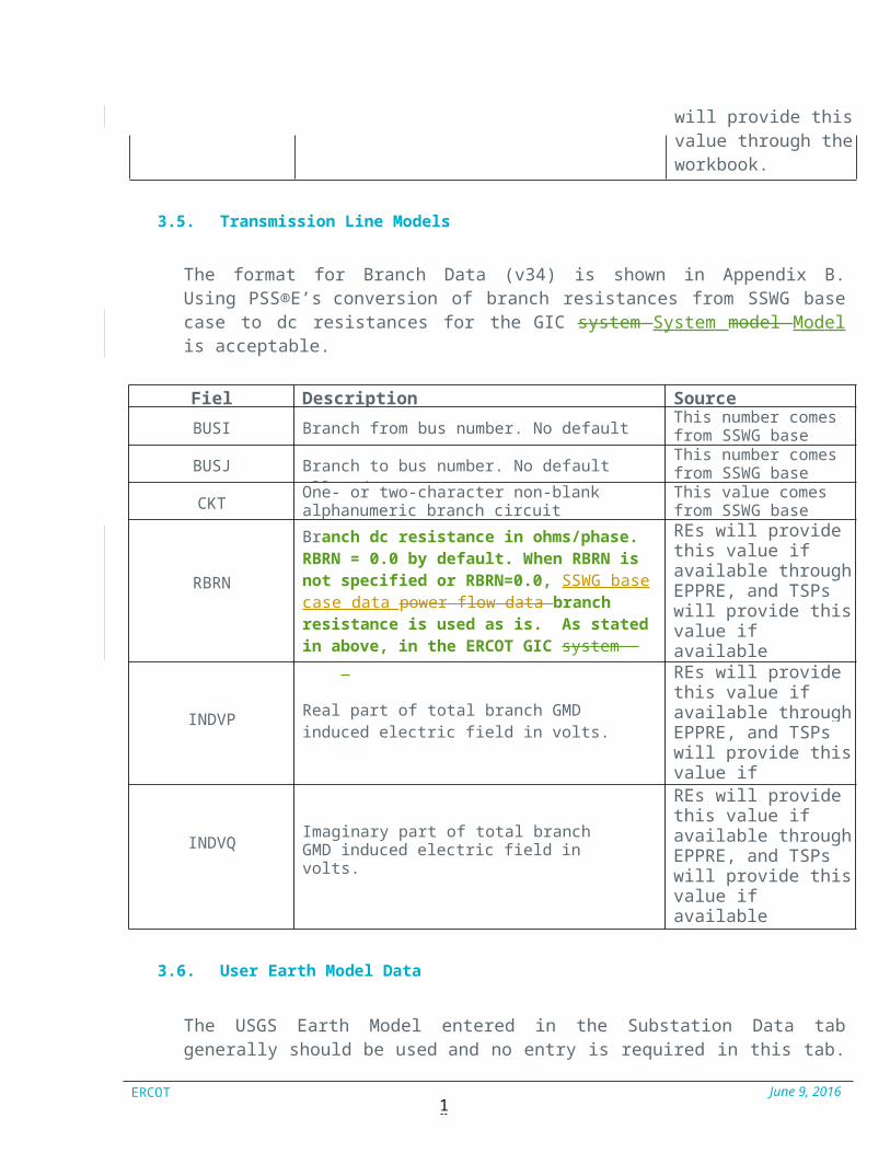
3.5. Transmission Line Models
The format for Branch Data (v34) is shown in Appendix B. Using PSS®E’s conversion of branch resistances from SSWG base case to dc resistances for the GIC system System m odel M odel is acceptable.
Field Description SourceBUSI Branch from bus number. No default allowed. This number comes
from SSWG base case.
BUSJ Branch to bus number. No default allowed. This number comes from SSWG base case.
CKT One- or two-character non-blank alphanumeric branch circuit identifier
This value comes from SSWG base case.
RBRN
Branch dc resistance in ohms/phase. RBRN = 0.0 by default. When RBRN is not specified or RBRN=0.0, SSWG base case data power f low dat a branch resistance is used as is. As stated in above, in the ERCOT GIC syst em Syst em modelModel, use the 1 megaohm method for all series capacitors (RBRN = 1,000,000).
REs will provide this value if available through EPPRE, and TSPs will provide this value if availablethrough the workbook.
INDVP Real part of total branch GMD induced electric field in volts.
REs will provide this value if available through EPPRE, and TSPs will provide this value if availablethrough the workbook.
INDVQ Imaginary part of total branch GMD induced electric field in volts.
REs will provide this value if available through EPPRE, and TSPs will provide this value if availablethrough the workbook.
3.6. User Earth Model Data
The USGS Earth Model entered in the Substation Data tab generally should be used and no entry is required in this tab. If the USGS Earth Model is not desired, then a new user Earth Model can be created using this tab and entered on the Substation Data tab.
A total of up to 50 user earth models are allowed. Also, each earth model may have up to 25 layers. Use as many records needed to specify the data. The thickness

ERCOT June 9, 201613
ofRO S A ppro ve d: J un e 9, 20 16
ERCOT June 9, 201613
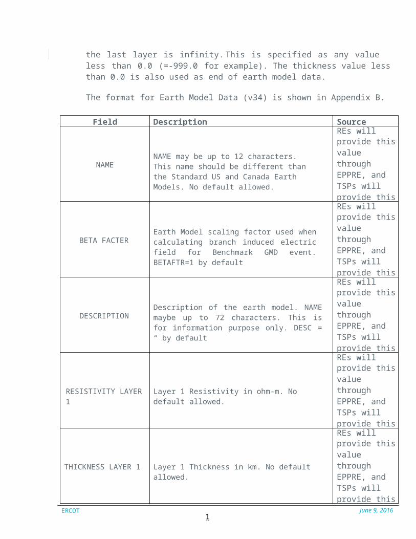
the last layer is infinity. This is specified as any value less than 0.0 (=-999.0 for example). The thickness value less than 0.0 is also used as end of earth model data.
The format for Earth Model Data (v34) is shown in Appendix B.
Field Description Source
NAMENAME may be up to 12 characters. This name should be different than the Standard US and Canada Earth Models. No default allowed.
REs willprovide this value through EPPRE, and TSPs will provide this value through the workbook.
BETA FACTEREarth Model scaling factor used when calculating branch induced electric field for Benchmark GMD event. BETAFTR=1 by default
REs willprovide this value through EPPRE, and TSPs will provide this value through the workbook.
DESCRIPTIONDescription of the earth model. NAME maybe up to 72 characters. This is for information purpose only. DESC = “ by default
REs willprovide this value through EPPRE, and TSPs will provide this value through the workbook.
RESISTIVITY LAYER 1 Layer 1 Resistivity in ohm-m. No default allowed.
REs willprovide this value through EPPRE, and TSPs will provide this value through the workbook.
THICKNESS LAYER 1 Layer 1 Thickness in km. No default allowed.
REs willprovide this value through EPPRE, and TSPs will provide this value through the workbook.
RO S A ppro ve d: J un e 9, 20 16
ERCOT June 9, 201614
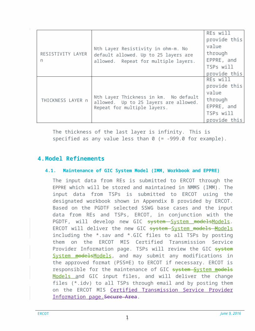
RESISTIVITY LAYER nNth Layer Resistivity in ohm-m. No default allowed. Up to 25 layers are allowed. Repeat for multiple layers.
REs willprovide this value through EPPRE, and TSPs will provide this value through the workbook.
THICKNESS LAYER n Nth Layer Thickness in km. No default allowed. Up to 25 layers are allowed. Repeat for multiple layers.
REs willprovide this value through EPPRE, and TSPs will provide this value through the workbook.
The thickness of the last layer is infinity. This is specified as any value less than 0 (= -999.0 for example).
4. Model Refinements
4.1. Maintenance of GIC System Model (IMM, Workbook and EPPRE)
The input data from REs is submitted to ERCOT through the EPPRE which will be stored and maintained in NMMS (IMM). The input data from TSPs is submitted to ERCOT using the designated workbook shown in Appendix B provided by ERCOT. Based on the PGDTF selected SSWG base cases and the input data from REs and TSPs, ERCOT, in conjunction with the PGDTF, will develop new GIC system System m odelsM odels. ERCOT will deliver the new GIC s ystem S ystem m odels M odels including the *.sav and *.GIC files to all TSPs by posting them on the ERCOT MIS Certified Transmission Service Provider Information page. TSPs will review the GIC system System m odelsM odels, and may submit any modifications in the approved format (PSS®E) to ERCOT if necessary. ERCOT is responsible for the maintenance of GIC system System m odels M odels and GIC input files, and will deliver the change files (*.idv) to all TSPs through email and by posting them on the ERCOT MIS Certif ied T ransm ission Service Provider Inf orm ation page.Secure Area.
ERCOT June 9, 201615
RO S A ppro ve d: J un e 9, 20 16

ERCOT June 9, 201615
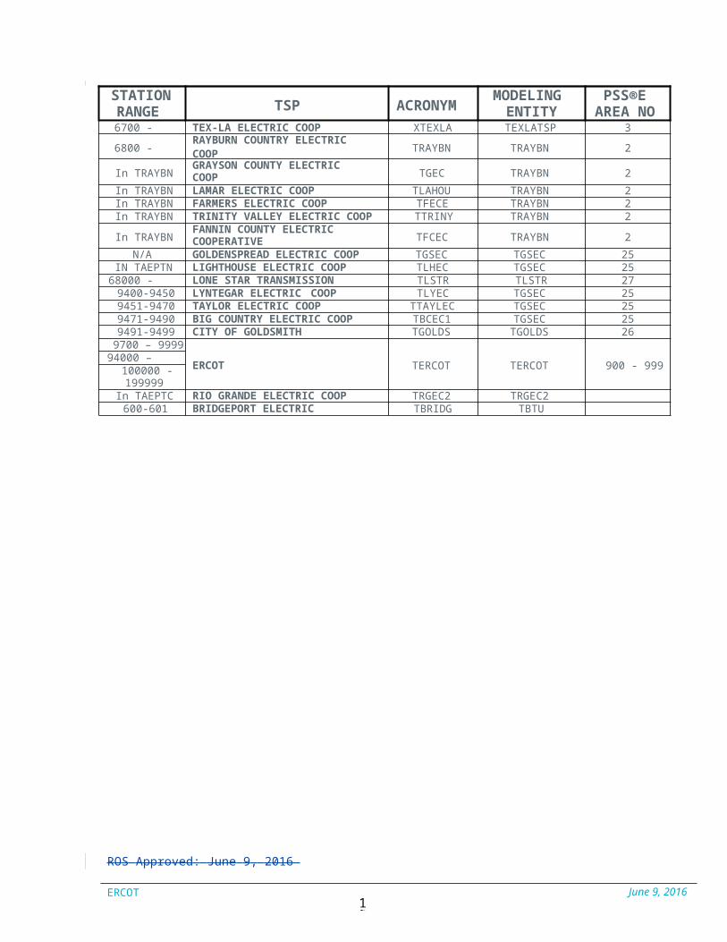
Appendix A - Station Number Range
STATIONRANGE TSP ACRONYM MODELING
ENTITYPSS®E
AREA NO1 - 799 BRAZOS ELECTRIC POWER COOP. TBREC TBREC 1133000 - 36999
32050 - 32999 BRYAN, CITY OF TBTU TBTU 22
900 - 934 DENTON MUNICIPAL UTILITIES,CITY OF TDME TDME 19
800 - 899 GARLAND, CITY OF TGAR TGAR 20
935 - 955 GREENVILLE ELECTRIC UTILITYSYSTEM TGEUS TGEUS 21
956 - 999 TEXAS MUNICIPAL POWER AGENCY TTMPA TTMPA 129500 - 96991000 - 4999 ONCOR TONCOR TONCOR 110000 - 31999
32000 - 32049 COLLEGE STATION, CITY OF TCOLGS TCOLGS 2337000 - 39999 TEXAS NEW MEXICO POWER CO. TTNMP TTNMP 1740000 - 49999 CENTERPOINT TCNPE TCNPE 4
5000 - 5499 CPS ENERGY TCPSE TCPSE 550000 - 54999
5500 - 5899 SOUTH TEXAS ELECTRIC COOP TSTEC TSTEC 1355000 - 589995910 - 5919 SOUTH TEXAS POWER PLANT TCNPE TCNPE 107000 – 7899
70000 - 78999LCRA TRANSMISSION SERVICESCORPORATION (TSC) TLCRA TLCRA 7
In TLCRA BANDERA ELECTRIC COOP TBDEC TLCRAIn TLCRA BLUEBONNET ELECTRIC COOP TBBEC TLCRAIn TLCRA CENTRAL TEXAS ELECTRIC COOP TCTEC TLCRA
In TLCRA GUADALUPE VALLEY ELECTRICCOOP TGVEC TLCRA
In TLCRA NEW BRAUNFELS UTILITIES TNBRUT TLCRAIn TLCRA PEDERNALES ELECTRIC COOP TPDEC0 TLCRAIn TLCRA SAN BERNARD ELECTRIC COOP TSBEC TLCRA
79000-79499 CROSS TEXAS TRANSMISSION TCROS TCROS 308000 – 8999
80000 - 89999 AMERICAN ELECTRIC POWER - TCC TAEPTC TAEPTC 8
79500-79699 SHARYLAND TSLND1 TSLND1 189000 – 9399
90000 - 93999 AUSTIN ENERGY TAEN TAEN 9
5920 - 5929 EAST HIGH VOLTAGE DC TIE TAEPTC 165930 - 5989 PUBLIC UTILITY BOARD
OF BROWNSVILLE TBPUB TBPUB 1559300 - 59899
59900 - 59999 WIND ENERGY TRANSMISSIONTEXAS WETT WETT 29
6000 - 6699AMERICAN ELECTRIC POWER- TNC TAEPTN TAEPTN 660000 - 67999
69000 - 69999
In TAEPTN COLEMAN COUNTY ELECTRICCOOP TCOLMN TGSEC 25
In TAEPTN CONCHO VALLEY ELECTRIC COOP TCVEC2 TGSEC 25In TAEPTN RIO GRANDE ELECTRIC COOP TRGEC1 AEPTN
In TAEPTN SOUTHWEST TEXAS ELECTRICCOOP TSWEC1 TGSEC 25
In TAEPTN TAYLOR ELECTRIC COOP. TECX TGSEC 256096 - 6096 NORTH HIGH VOLTAGE DC AEPTN 14
RO S A ppro ve d: J un e 9, 20 16
ERCOT June 9, 201616
STATION TSP ACRONYM MODELING
ENTITYPSS®E
AREA 6700 - 6749 TEX-LA ELECTRIC COOP XTEXLA TEXLATSP 3
6800 - 6949 RAYBURN COUNTRY ELECTRICCOOP TRAYBN TRAYBN 2
In TRAYBN GRAYSON COUNTY ELECTRICCOOP TGEC TRAYBN 2
In TRAYBN LAMAR ELECTRIC COOP TLAHOU TRAYBN 2In TRAYBN FARMERS ELECTRIC COOP TFECE TRAYBN 2In TRAYBN TRINITY VALLEY ELECTRIC COOP TTRINY TRAYBN 2
In TRAYBN FANNIN COUNTY ELECTRICCOOPERATIVE TFCEC TRAYBN 2
N/A GOLDENSPREAD ELECTRIC COOP TGSEC TGSEC 25IN TAEPTN LIGHTHOUSE ELECTRIC COOP TLHEC TGSEC 25
68000 - 68999 LONE STAR TRANSMISSION TLSTR TLSTR 279400-9450 LYNTEGAR ELECTRIC COOP TLYEC TGSEC 259451-9470 TAYLOR ELECTRIC COOP TTAYLEC TGSEC 259471-9490 BIG COUNTRY ELECTRIC COOP TBCEC1 TGSEC 259491-9499 CITY OF GOLDSMITH TGOLDS TGOLDS 26
9700 – 9999
ERCOT TERCOT TERCOT 900 - 99994000 – 99999100000 -199999
In TAEPTC RIO GRANDE ELECTRIC COOP TRGEC2 TRGEC2600-601 BRIDGEPORT ELECTRIC TBRIDG TBTU
RO S A ppro ve d: J un e 9, 20 16
ERCOT June 9, 201617
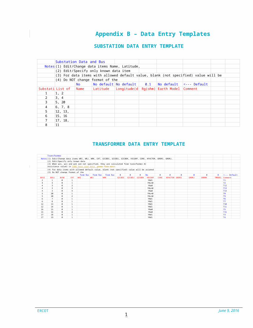
Appendix B – Data Entry Templates
SUBSTATION DATA ENTRY TEMPLATE
Substation Data and Bus GroupsNotes (1) Edit/Change data items Name, Latitude, Longitude, Rg and Comment.
(2) Edit/Specify only known data item values.(3) For data items with allowed default value, blank (not specified) value will be assigned as default value in PSSE GIC module.(4) Do NOT change format of the worksheet.
No default No default No default 0.1 No default <--- Default ValuesSubstation List of Buses Name Latitude (deg) Longitude(deg) Rg(ohm) Earth Model Comment
1 1, 22 3, 43 5, 204 6, 7, 85 12, 13, 146 15, 167 17, 18, 198 11
TRANSFORMER DATA ENTRY TEMPLATE
Transformer DataNotes (1) Edit/Change data items WRI, WRJ, WRK, CKT, GICBDI, GICBDJ, GICBDK, VECGRP, CORE, KFACTOR, GRDRI, GRDRJ, GRDRK, TMODEL and Comment.
(2) Edit/Specify only known data item values.(3) When wri, wrj and wrk are not specified, they are calculated from transformer AC resistance values in SSWG base case data. pow e r f l ow data.
(4) For data items with allowed default value, blank (not specified) value will be asigned as default value in PSSE GIC module.(5) Do NOT change format of the worksheet.
from Rac from Rac from Rac 0 0 0 No default 0 0 0 0 0 0 <--- Default ValuesBUSI BUSJ BUSK CKT WRI (ohm/ph) WRJ (ohm/ph) WRK (ohm/ph) GICBDI GICBDJ GICBDK VECGRP CORE KFACTOR GRDRI (ohm) GRDRJ (ohm) GRDRK (ohm) TMODEL Comment
2 1 0 1 YNd1 T14 3 0 1 YNyn0 T24 3 0 2 YNa0 T124 3 0 3 YNyn0 T134 3 0 4 YNa0 T145 20 0 1 YNyn0 T85 20 0 2 YNyn0 T96 7 0 1 YNd1 T66 8 0 1 YNd1 T7
12 13 0 1 YNd1 T1012 14 0 1 YNd1 T1116 15 0 1 YNa0 T515 16 0 2 YNa0 T1517 18 0 1 YNd1 T317 19 0 1 YNd1 T4
RO S A ppro ve d: J un e 9, 20 16

ERCOT June 9, 201618
FIXED SHUNT DATA ENTRY TEMPLATE
Bus Fixed Shunt DataNotes (1) Edit/Change data items BUS, ID, RFXSH, RGRDFXSH and Comment.
(2) Edit/Specify only known data item values.(3) No default fixed shunts considered. Specify needed in-service fixed shunts.(4) Do NOT change format of the worksheet.
No default 0 <--- Default ValuesBUS ID RFXSH (ohm/ph) RGRDFXSH (ohm) Comment
BRANCH DATA ENTRY TEMPLATE
Branch DataNotes (1) Edit/Change data items BUSI, BUSJ, CKT, RBRN, INDUCEDV and
Comment.(2) Edit/Specify only known data item values.(3) When RBRN is not specified, branch AC resistance from SSWG base case data p ow e r f l ow d ata is used.
(4) Branch GMD Induced Electric Field, INDUCEDV = INDVP + j INDVQ.(5) When INDUCEDV is not specified, GIC activity calculates it according to GMD event specified.(6) When INDUCEDV is specified, it is used as GMD induced electric field on that branch.(7) When INDVP=INDVQ=0.0, that branch is treated as underground cable, part of DC network but does not have GMD induced electric field.(8) INDUCEDV is specified in volts. This is a voltage with positive polarity at BUSJ (To Bus).(9) BUSI and BUSJ order should match that in P SS ESSWG base case data. p ow e r f l ow d ata.(10) Do NOT change format of the worksheet.
from Rac No default No default <--- Default ValuesBUSI BUSJ CKT RBRN (ohm/ph) INDVP (V) INDVQ (V) Comment
2 3 12 17 14 5 14 5 24 6 14 15 15 6 15 11 16 11 16 15 16 15 2
11 12 116 17 116 20 117 20 1
ERCOT June 9, 201619
RO S A ppro ve d: J un e 9, 20 16
ERCOT June 9, 201619
EARTH MODEL DATA ENTRY TEMPLATE
User Earth Model DataNotes (1) Provide each Earth Model Data co l u mn w i s eco l u mn w i se and from
(2) The thickness of the last layer is infinity. Specify this as any number less than (3) The numbers of layers allowed for each earth model are 25 or less.(4) Model name should be unique and up toup to 12 (5) Model name should be different than standard model names defined in PSSE GIC (6) Do NOT change format of the worksheet.
NAMEBETA FACTORDESCRIPTION
Resistivity (ohm-m) Layer 1Thickness (km) Layer 1
Resistivity (ohm-m) Layer 2Thickness (km) Layer 2
Resistivity (ohm-m) Layer 3Thickness (km) Layer 3
Resistivity (ohm-m) Layer 4Thickness (km) Layer 4
Resistivity (ohm-m) Layer 5Thickness (km) Layer 5
Resistivity (ohm-m) Layer 6Thickness (km) Layer 6
Resistivity (ohm-m) Layer 7Thickness (km) Layer 7
Resistivity (ohm-m) Layer 8Thickness (km) Layer 8
Resistivity (ohm-m) Layer 9Thickness (km) Layer 9
Resistivity (ohm-m) Layer 10Thickness (km) Layer 10
Resistivity (ohm-m) Layer 11Thickness (km) Layer 11
Resistivity (ohm-m) Layer 12Thickness (km) Layer 12
Resistivity (ohm-m) Layer 13Thickness (km) Layer 13
Resistivity (ohm-m) Layer 14Thickness (km) Layer 14
RO S A ppro ve d: J un e 9, 20 16