Embed Size (px)
DESCRIPTION
Equipment Design Done by: Sara Saad Al-Quhaim (Group leader). Equipment Design:. Distillation Column ( C-201) Distillation Column ( C-202) Cooler (E-103) Compressor ( K-100). Distillation Design:. Number of Stages (No. of stages) min = 25 (from HYSYS) Efficiency = 75%(Assumed) - PowerPoint PPT Presentation
Citation preview

Equipment DesignDone by:
Sara Saad Al-Quhaim (Group leader)

Distillation Column ( C-201)Distillation Column ( C-202)Cooler (E-103)Compressor ( K-100)
Equipment Design:

Distillation Design:
Number of Stages
(No. of stages) min = 25 (from HYSYS)
Efficiency = 75% (Assumed)
Actual stages = (No. of stages) min / Efficiency
=33

Calculation of actual number of stages
( Short-cut Method):
Water ( heavy) a= -7.831b= 1.7399c= -2.2505d= -1.9828
API method:
Pr vap= Pc*100*EXP((Tr^-1)*( at+bt^1.5+ct^2.6+dt^5)Y= 18.9621182α= 1 (relative volatility)

Methanol ( light )
a= -8.6413b= 1.0671c= -2.3184d= -1.678XF= 0.096XD= 0.996XB= 0.0000005
API method:
Pr vap= Pc*100*EXP((Tr^-1)*( at+bt^1.5+ct^2.6+dt^5)Y= 79.90817981α= 4.21409565

α F D B
water 1 87.4 0.009602458 87.391972 heavy
Methanol 4.21409565 12.6 12.57922028 0.0192049 light
Nm = Log [ XLK/ XHK]d [XLK/ XHK]b ( minimum number of stages)
Log LK
( Fenske equation)
q=0.98909 (liquid)
[ xf - ] = 1-q

xf α α * xf ө=2.8 ө=3.1
0.874015748 1 0.874 -0.485564304 -0.416198
0.125984252 4.21409565 0.531 0.375441144 0.4765387
= 3.013 by interpolation
[ xd - ] = Rm +1

xd α α xd (α xd/α-ө)
0.000762777 1 8E-04 -0.000378925
0.999237223 4.21409565 4.211 3.505866695
Rm= 2.50548777Rm/(Rm+1)= 0.714732994
R= 2.8R/(R+1)= 0.736842105

Nm/N= 0.33
N= 32.866
Note: The actual number of stages =33 stages

Where:Lw: liquid flow rate, kmol/hrρL: liquid density,kg/m3Vw: vapor flow rate, kmol/hrρv :vapor density, kg/m3FLv: Liquid-vapor factor
5.0)(*l
v
VW
LWFLV
Tray spacing= 0.55 ( from hysys)
Using figure to find K1

5.0)(1v
vlKUf
uf : flooding vapor velocity, m/s
XUFUV *uv: maximum velocity, m/s.
x: percentage of flooding at max flowrate.( assume 85”% )
Maximum volumetric flow rate
3600*
*
v
MV WtW

Uv
VAnet
max Anet: Net area required, m2
Taking downcomer area
as 12 percent of total12.01
AnAdCross sectional area of
downcomer=
4*c
c
AD Column Diameter

diameterEfficieny
spacingtraystagesActualH
.*.Column Height
l
MLMVL wtbottom
*3600
*
Maximum volumetric liquid rate
Liquid flow arrangement

Ac = π/4 Dc2 Total column cross sectional area
Net area available for vapor liquid
Active or bubbling area
Ah = 0.1 AaHole area

Ad/Ac*100
Find lw/Dc from Figure
Find Weir Length (lw)
3600*)( Wt
WW
MLLMax
Minimum liquid rate = 0.7* Max (Lw)

Maximum how =750(Lw/(ρL lw))(2/3)Minimum how =750(Lw/(ρL lw))(2/3) Weir crest
At minimum rate hw=50mm + how, from Figure 11.30 Find K2

uh (min) =(K2-0.90(25.4-dh))/ρv0.5 Minimum vapor velocity
Hole diameter =5mm
actual minimum vapor velocity = min vapor rate /Ah
Hole area
Note: actual minimum vapor velocity should be greater than Uh
Taking;Plate thickness/hole dia. = 1 Ah/Ap ( perforated area) = Ah/Aa from figure ( orifice cofficient) Co = 0.84

Dry plate drop= hd = 51(uh/Co)2(ρv/ρL)
Vapor velocity
Residual head (hr) = (12.5*103)/ρL
Total plate pressure drop (ht) = hd+hw+how+hr

Downcomer pressure drop (hap) = hw-10Area under apron (Aap) = lw *hap*0.001
hdc =
2)*
(*166LAP
wd
A
L
hdc= Head loss in downcomer
Back-up in downcomer (hb) = hw+how+ht+hdc
Weir crest
hb less than tray spacing , so tray spacing is acceptable.

Residence Time
Uv = Bottom V / An Percent flooding=
flowmassliquid
hAtr Lbd
tr: residence time, should be > 3 s
Downcomer area
Down comer backup
f
vu
u
From figure, find ψ below 0.1( fractional entrainment)

Calculate lw/Dc
From figure find
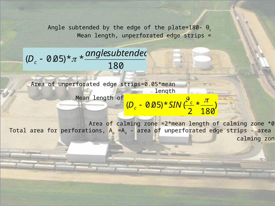
180
.**)05.0(
subtendedangleDc
Angle subtended by the edge of the plate=180- θc
Mean length, unperforated edge strips =
Area of unperforated edge strips=0.05*mean lengthMean length of calming zone =
Area of calming zone =2*mean length of calming zone *0.05Total area for perforations, Ap =Aa - area of unperforated edge strips - area of
calming zone
)180
*2
(*)05.0( c
c SIND

Ah/Ap from figure, find lp/dh
satisfactory within 2.5 to 4

Number of holes:
Area of one hole= 23)10*5(*4
Total number of holes = Ah / 1.963E-05
Holes on one plate = total Number of holes/Area of one
For condenser:
Material Carbon SteelArea of condenser = TU
Q
*

For reboiler:
Material Carbon SteelArea of reboiler= TU
Q
*
CcPSE
priThickness
*6.0*
* Where:
ri = Inside radius of the shell, inP =Maximum allowable internal
pressureS = Maximum allowable working
stressE = Efficiency of joints
Cc = Allowance for corrosion, in

Equipment Name Distillation column
Objective To separate methanol from Alcohols
Equipment Number C-201
Designer Sara Al-Quhaim
Type Tray column
Location Ethanol Production
Material of Construction Carbon steel
Insulation Minral wool and glass fiber
Cost ($) $454,118
Column Flow Rates
Feed (kgmole/hr) 6176Recycle
(kgmole/hr)-
Distillate (kgmole/hr) 1317Bottoms
(kgmole/hr)5474
Key Components
Light Methanol Heavy Water
Dimensions
Diameter (m) 4.6 Height (m) 41.3
Number of Trays 69 Reflux Ratio 90
Tray Spacing 0.5 Type of tray Sieve trays
Number of Holes 64266
Cost
Vessel $194,400 Trays $63,333
Condenser Unit $89,000 Reboiler $105,208
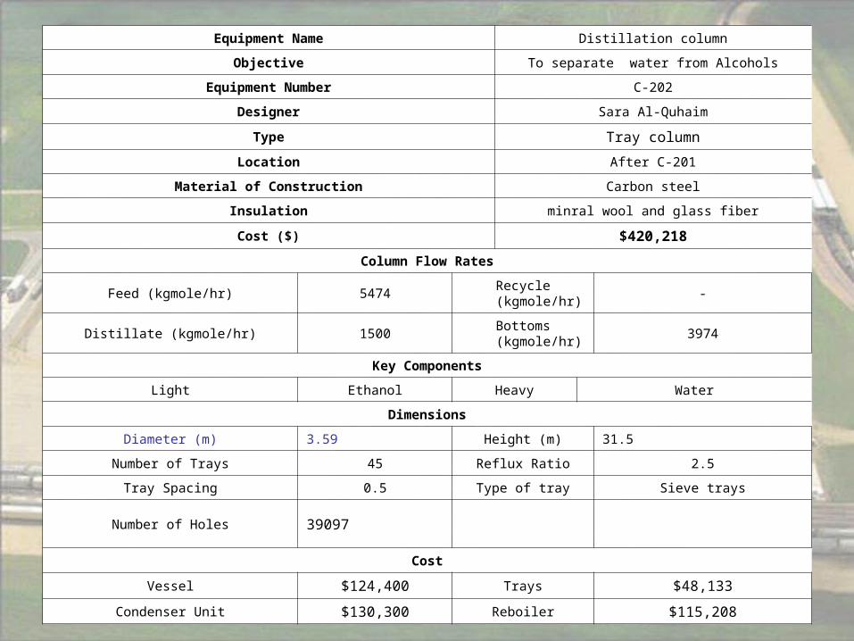
Equipment Name Distillation column
Objective To separate water from Alcohols
Equipment Number C-202
Designer Sara Al-Quhaim
Type Tray column
Location After C-201
Material of Construction Carbon steel
Insulation minral wool and glass fiber
Cost ($) $420,218
Column Flow Rates
Feed (kgmole/hr) 5474 Recycle (kgmole/hr) -
Distillate (kgmole/hr) 1500 Bottoms (kgmole/hr) 3974
Key Components
Light Ethanol Heavy Water
Dimensions
Diameter (m) 3.59 Height (m) 31.5
Number of Trays 45 Reflux Ratio 2.5
Tray Spacing 0.5 Type of tray Sieve trays
Number of Holes 39097
Cost
Vessel $124,400 Trays $48,133
Condenser Unit $130,300 Reboiler $115,208

Cooler design (heat exchanger)

TmCQ p
hQ
m
T
-
= Heat load transfer in the hot side, KW.
Mass flow rate in Kg/s.
Temperature difference of the inlet and outlet.

)(
)(ln
)()(
12
21
1221
tT
tTtTtT
Tlm
1T
2T
1t
2t
Inlet shell side fluid temperature (oC).
Outlet shell side fluid temperature (oC).
Inlet tube side temperature (oC).
Outlet tube temperature (oC).
)(
)(
12
21
tt
TTR
)(
)(
11
12
tT
ttS
Measure of temperature efficiency

lmtm TFT -
tFTemperature correction factor.
At R and S
Estimate U from table 12.1
mTU
QA
Provisional area

Take: Tube outside diameter(do) =20mm
Tube inner diameter(di) =16mm
Tube length(L) =4.88m
DLA Area of one tube
tN A/ A one tube Number of tubes
1
1
10 )( nt
b K
NdD Bundle diameter
K1, n1 depend on number of passes

ClearanceDD bs Shell diameter

2)(4 ic dA
Tube cross sectional area
4tN
Pass
Tubes Tube per passes
Pass
TubesAA ct Total flow area
tm A
mU Tube mass velocity

ref
mt
UU
Tube linear velocity
2.0
8.0 )*)02.035.1(*4200(
i
ti
d
Uth
Heat transfer coefficient inside the tube
itdU
Ref
p
k
C Pr

i
hfi d
jkh
33.0Re(Pr)
ih
hj
fk
Inside coefficient (W/m2 oC).
Tube side heat transfer factor.
Thermal conductivity of stream.
From l/Di and Re
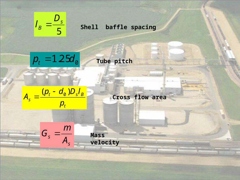
5s
B
Dl Shell baffle spacing
025.1 dpt Tube pitch
t
Bsts p
lDdpA
)( 0 Cross flow area
ss A
mG Mass velocity

)917.0(1.1 2
02
0
dpd
d te Equivalent diameter
esdG
Re Pr =Cp / kf At 25% baffle cut find jh

hs =
3
1
rehe
f PRjd
K
ii
o
idi
o
w
i
oo
odoo hd
d
hd
d
K
d
dLNd
hhU
11
2
111
Overall heat transfer coefficient
odh
idh
Outside coefficient (fouling factor).
Inside coefficient (fouling factor).

25.28
2t
m
wifpt
u
d
LjNP
Jf= friction factor
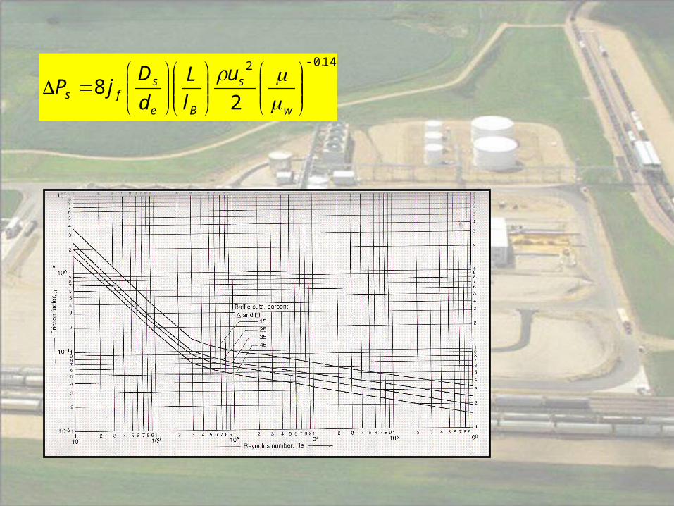
14.02
28
w
s
Be
sfs
u
l
L
d
DjP

CcPSEj
t i
6.0
PrShell Thickness
t
P
ir
jE
S
cC
-
Shell thickness (in).
Maximum allowable internal pressure (psig).
Internal radius of shell before allowance corrosion is added (in).
Efficiency of joints.
Working stress (psi).
Allowance for corrosion (in)

Equipment Name Cooler
ObjectiveTo cooled the feed stream entering the
reactor
Equipment Number E-101
Designer Sara Al-Quhaim
TypeShell and tube heat exchanger(Floting
head, large)
Location After the compressor K-102
Utility Chilled water
Material of Construction Carbon steel
Insulation Glass wool
Cost ($) $570,376 (for three)
Operating Condition
Shell Side
Inlet temperature (oC) 76.11Outlet temperature
(oC)52.738
Tube Side
Inlet temperature (oC) 25Outlet temperature
(oC)35
Number of Tube Rows 2 Number of Tubes 3022
Tube bundle Diameter (m) 0.9534365 Shell Diameter (m) 1.0234365
Q total (Kw) 5922.869045 LMTD (oC) 33.646828
U (W/m2 oC) 213..57628Heat Exchanger
Area (m2)926.47649

Compressor Design

11 1
2 2
n
nP T
P T
n = Compression factor
1 2( )
1
nR T TW
n
W = work done (Btu/Ibmol)
R = Cp/Cv
*Hp W M M= mol flow rate (Ibmol/hr)

1
1
nnEp
KK
K = (Mwt*CP)/(Mwt*CP-1.986)
Ep = Efficiency of compressor %

Equipment Name Compressor
Objective To increase the pressure of stream 25
Equipment Number K100
Designer Sara Saad Al-Quhaim
Type Air, centrifugal, 125 psi
Location After C-202
Material of Construction Carbon steel
Insulation Quartz wool
Cost $186176.25
Operating Condition
Inlet Temperature (oC) 67.132Outlet
Temperature (oC)
186.48
Inlet Pressure (psia) 8.7020Outlet
Pressure (psia)
60.0000
Efficiency (%) 133.3817 Power (Hp) 543.6356

Thank You


![Saad Report[1]](https://img.pdfslide.us/doc/110x75/577dab591a28ab223f8c4e93/saad-report1.jpg)