Embed Size (px)
Citation preview

ENGINEERING AND CONSTRUCTION BULLETIN
No. 2014-16 Issuing Office: CECW-CE Issued: 29 Jul 2014 Expires: 29 Jul 2016
Subject: Quality Assurance Representative’s Guide for Building Envelopes
Applicability: Directive and Guidance.
References:
a. Memorandum, DoD (AT&L), 10 Nov 2013, Subject: Department of Defense Sustainable Buildings Policy
b. Memorandum, ASA (IE&E), 16 Dec 2013, Subject: Sustainable Design and Development Update (Environmental and Energy Performance)
c. Unified Facilities Criteria 1-200-02, 1 Mar 2013, Subject: High Performance and Sustainable Building Requirements
d. Unified Facilities Criteria 3-101-01, 28 Nov 2011, Subject: Architecture
e. Engineering and Construction Bulletin (ECB) 2012-16, 1 May 2012, Subject: Building Air Tightness and Air Barrier Continuity Requirements
f. Unified Facilities Criteria 3-110-03, 1 May 2012, Subject: Roofing
g. Engineering Regulation 415-1-11, 1 Jan 2013, Subject: Biddability, Constructability, Operability, Environmental and Sustainability (BCOES) Reviews
h. Engineer Pamphlet 415-1-261, 1 Aug 1992, Subject: Quality Assurance Representative’s Guide Vol. 1-5
i. Whole Building Design Guide (WBDG) website (http://www.wbdg.org), National Institute of Building Sciences
1. Purpose. The purpose of this Engineering and Construction Bulletin (ECB) is to provide direction and guidance on the inspection and quality assurance process for high performance building envelopes. This ECB is effective when issued. Projects in process shall implement requirement to the extent practical for the current phase with the expectation to achieve full compliance in follow-on project phases. All projects planned for construction award in FY15 and beyond shall be in compliance with this policy.
2. Objective. This policy applies to all construction Quality Assurance (QA) programs executed by USACE regardless of client agency or project funding source. On Joint Installations, the supporting Component guides all construction policy and guidance and may supersede this policy or have an alternate format for reporting test results in lieu of the attached template. For overseas construction activities on permanent basing and in support of

ECB 2014-16 Subject: Quality Assurance Representative’s Guide for Building Envelopes
2
contingency operations, this policy will apply to the greatest extent practical considering mission objectives and Host Nation agreements. This guidance will become a part of permanent USACE doctrine by being integrated into the Quality Assurance Representative’s Guide (reference h) or similar Headquarters publication prior to the expiration of this ECB.
3. Introduction. The Department of the Army is committed to delivering high performance sustainable buildings in all new construction and major renovation efforts (reference a). This policy has been used to inform the performance requirements adopted by our facilities criteria, such as that in references b and c. Further, ECB 2012-16 (reference d) provides specific guidance for the design, application and testing of air barriers.
a. The performance of our buildings can be quantified by how well they protect the interior from the exterior environmental conditions. Specifically, how well they limit the intrusion of air, heat, and water (as both liquid and vapor). Both designers and constructors should be keenly aware of how the building assemblies control each of these elements, ensuring that the controlling layers are continuous to form a complete envelope wrapping all six sides of the interior space. Careful consideration must be given as to how each of these layers of the envelope is sequentially constructed to ensure performance continuity through all corners and material transitions.
b. In reviews of many high performance buildings, we have found strategies that can be employed during the project construction phase to ensure building envelopes have been appropriately detailed, constructed, and tested to assure high performance. The attached guide serves as a reference manual for construction activities to ensure the quality and functional requirements of High Performance Building Envelopes are met.
4. Policy. Certain components of the building envelope are critical to overall building performance. At a minimum, Quality Assurance (QA) plans and programs are to include the following topical areas. Components within these categories applicable to the project are to be specifically addressed. A Quality Assurance Representative’s Guide for Building Envelopes is attached to this ECB to assist with the QA plan development and for use in the field for construction QA processes.
General Overview and Three Phase Control Process Exterior Cladding Roof Coverings Fenestration Thermal Bridges Thermal Envelope and Insulation Air, Vapor and Water Control Layers Water Drainage Wall Types Air Leakage Test Protocol Air Leakage Specification Reporting of Test Results
5. Further Guidance. To provide assistance with identifying critical components and appropriate language for inclusion in QA plans for specific projects, the following resources are available to be used in concert with the aforementioned attachment:
ECB 2014-16 Subject: Quality Assurance Representative’s Guide for Building Envelopes
3
Air Barrier Association of America (ABAA): http://www.airbarrier.org/
UFC 1-200-02 High Performance and Sustainable Building Requirements: http://www.wbdg.org/ccb/DOD/UFC/ufc_1_200_02.pdf
UFC 3-101-01 Architecture: http://www.wbdg.org/ccb/DOD/UFC/ufc_3_101_01.pdf
UFGS 07 27 10.00 10 Building Air Barrier System: UFGS 07 05 23 Pressure Testing an Air Barrier System for Air Tightness:
http://www.wbdg.org/ccb/DOD/UFGS/UFGS%2007%2005%2023.pdf
6. Exemption. A request for an exemption through HQ USACE, Engineering and Construction Division, POC Eric Mucklow: [email protected] and may be made for any specific requirement included herein or by reference that the PDT determines would adversely affect mission performance, security requirements, health, safety, or welfare. The exemption shall only apply to the specific requirements in conflict. Any approved exemptions to this policy shall be documented with reference to the specific requirement in conflict and included in the project documentation.
7. Point of Contact. Eric Mucklow is the Headquarters USACE point of contact for this policy and is available via email at [email protected].
Encl. JAMES C. DALTON, P.E., SES Chief, Engineering, and Construction U.S. Army Corps of Engineers STACEY K. HIRATA, P.E., SES RICHARD A. HANCOCK, P.E., SES Chief, Installation Support Division Chief, Programs Integration Division Directorate of Military Programs Directorate of Military Programs
Quality Assurance
Representative’s Guide
Volume 6:
Building Envelopes
EP 415-1-261 Volume 6
31 July 2014
Approved for Public Release. Distribution is Unlimited

EP 415-1-216 Vol.6 31 JUL 2014
Published by: Headquarters, US Army Corps of Engineers
Engineering & Construction Division 441 G Street NW
Washington, DC 20314
Point of Contact: Eric Mucklow
eric.mucklow @ usace.army.mil
Approved for Public Release
Distribution: Unlimited
EP 415-1-216 Vol.6 31 JUL 2014
i
CONTENTS
CHAPTER 1 - General Overview and the Three Phase Control Process ....................................... 1
1-1. General Overview. ........................................................................................................... 1
1-2. Three Phase Control Process. ........................................................................................... 1
CHAPTER 2 - Exterior Cladding ................................................................................................... 5
2-1. Definitions. ....................................................................................................................... 5
2-2. Materials. .......................................................................................................................... 5
2-3. Applications. .................................................................................................................... 6
2-4. QA activities. .................................................................................................................... 6
CHAPTER 3 - Roof Coverings..................................................................................................... 13
3-1. Definitions. ..................................................................................................................... 13
3-2. Materials. ........................................................................................................................ 13
3-3. Applications. .................................................................................................................. 14
3-4. QA activities. .................................................................................................................. 14
CHAPTER 4 - Fenestrations ......................................................................................................... 23
4-1. Definitions. ..................................................................................................................... 23
4-2. Materials. ........................................................................................................................ 24
4-3. Applications. .................................................................................................................. 24
4-4. QA activities. .................................................................................................................. 25
CHAPTER 5 - Thermal Bridges ................................................................................................... 35
5-1. Definitions. ..................................................................................................................... 35
5-2. Materials. ........................................................................................................................ 36
5-3. Applications. .................................................................................................................. 36
5-4. QA activities. .................................................................................................................. 37
CHAPTER 6 - Thermal Envelope and Insulation ........................................................................ 41
EP 415-1-216 Vol.6 31 JUL 2014
ii
6-1. Definitions. ..................................................................................................................... 41
6-2. Materials. ........................................................................................................................ 41
6-3. Applications: .................................................................................................................. 42
6-4. QA activities. .................................................................................................................. 42
CHAPTER 7 - Air, Vapor and Water Control Layers .................................................................. 49
7-1. Definitions: ..................................................................................................................... 49
7-2. Materials: ........................................................................................................................ 49
7-3. Applications: .................................................................................................................. 51
7-4. QA Activities.................................................................................................................. 52
CHAPTER 8 - Water Drainage .................................................................................................... 61
8-1. Definitions. ..................................................................................................................... 61
8-2. Materials. ........................................................................................................................ 61
8-3. Applications. .................................................................................................................. 61
8-4. QA activities. .................................................................................................................. 62
CHAPTER 9 - Wall Types .......................................................................................................... 67
9-1. Overview. ....................................................................................................................... 67
9-2. Insulated Concrete Forms (ICF). .................................................................................... 67
9-3. Cold Formed Steel (CFS) Framing. ............................................................................... 69
9-4. Concrete Masonry Units (CMU). ................................................................................... 70
9-5. Autoclaved Aerated Concrete (AAC). ........................................................................... 72
9-6. Tilt-up and Pre-Cast Concrete Panels. ........................................................................... 74
CHAPTER 10 - Air Leakage Test Protocol ................................................................................. 77
10-1. Building Air Tightness Requirement. ......................................................................... 77
10-2. Performance Requirement and Substantiation. .......................................................... 77
10-3. Specifier and Witness Guidance. Application and Scope. ......................................... 78

EP 415-1-216 Vol.6 31 JUL 2014
iii
10-4. Defining the Test Boundary. ...................................................................................... 78
10-5. Whole Building Testing.............................................................................................. 78
10-6. Individual Room or Dwelling Testing. ....................................................................... 79
10-7. Test Spaces Contained within Larger Zones. ............................................................. 79
10-8. Larger Buildings. ........................................................................................................ 79
CHAPTER 11 - Air Leakage Specification .................................................................................. 81
11-1. General........................................................................................................................ 81
CHAPTER 12 - Testing Agency Guide ....................................................................................... 85
12-1. U.S. Army Corps of Engineers (USACE) Standard for Air Leakage. ....................... 85
12-2. Application and Scope. ............................................................................................... 85
12-3. Test Equipment Air flow Capacity. ............................................................................ 85
12-4. Building Envelope Pressure Measurement. ................................................................ 87
12-5. Interior Pressure Uniformity. ...................................................................................... 87
12-6. Pre-Test Inspection and Equipment Check. ............................................................... 87
12-7. Before Starting the Test .............................................................................................. 88
12-8. Performing the Test. ................................................................................................... 89
12-9. Reporting of Results. .................................................................................................. 90
12-10. Locating Leakage Sites with Pressurization and Depressurization. ........................... 92
12-11. Thermography Requirements. .................................................................................... 92
12-12. Infrared Imaging System Calibration. ........................................................................ 93
12-13. Infrared Imaging System Specifications. .................................................................... 93
Glossary and Acronyms ................................................................................................................ 94
Sample Test Report Template ..................................................................................................... 101

EP 415-1-216 Vol.6 31 JUL 2014
iv
THIS PAGE INTENTIONALLY LEFT BLANK

EP 415-1-216 Vol.6 31 JUL 2014
1
CHAPTER 1
General Overview and the Three Phase Control Process
1-1. General Overview.
Due to the complexity and variability of the building envelopes in construction, coupled with the variation in functions of Military and Civil Works vertical construction projects and the requirements associated with them, this Guide will attempt to canvas the most pertinent Quality Assurance related aspects of a High Performance Building Envelope in Military and Civil works construction and give the Quality Assurance Representative a foundation from which to ensure that the building envelope will meet the specified performance expectations required of it. The aspects covered in this guide are applicable to new vertical construction as well as renovation and retrofit construction projects.
1-2. Three Phase Control Process.
a. Prepatory Phase
(1) Drawings and Specifications
(a) During the prepatory phase meeting the QAR should ensure that the contractor and sub contractors have the most current sets of the contract drawings and specifications.
(b) Drawings and specifications should be thoroughly reviewed and discussed with all the applicable trades or craftsmen involved in the vertical construction of the building envelope.
(2) Submittals
(a) Material Submittals
Submittals should be reviewed for contract compliance as well as compliance to the Buy America Act. All submittals for either DOR approval or government approval should be approved before this phase of the three phase process. All applicable submittals should be present for the prepatory meeting for review and discussion.
Each material or assembly as stated above will have specific manufacture’s installation instructions and performance criteria. The QAR should be looking to these documents to ensure that the contractor or sub contractor is installing or applying these materials properly and within the application or installation parameters. Many of these materials come from a manufacturer as systems of components. For best results, it is recommended that the materials be consistent from a manufacturer if possible.
(3) Shop Drawings
(a) The QAR ensures that all shop drawings for assemblies such as curtain wall, windows, doors, store front assemblies, roof systems or other envelope specific components

EP 415-1-216 Vol.6 31 JUL 2014
2
interface with the air barrier and/or other control layers and that continuity is maintained between fenestration and systems.
(b) The QAR must ensure that specific assemblies identified for thermal bridge reduction in the contract drawing set not be changed by the shops drawings to the detriment of the design for this assembly. Due to the specifically designed nature of thermal bridges, deviations from a detail of this nature could result in the failure to reduce the thermal bridge. Any changes to the design must be validated by the DOR before construction begins. The QAR should always involve the Contracting Officer or Contracting Officers Representative before changes are made to the design of the assembly.
(4) Schedule/Sequence
(a) The schedule and sequence of construction of the various features of the building envelope may occur at different times throughout the life of the project. Proper sequence and coordination entail ensuring that the substrates are complete, ready to accept or have installed the control layer, insulation fenestration or roof assembly and are free of any material that would damage or alter the material or assembly and its dedicated function once in place. Coordination with the trades should be discussed and those specific aspects of the other features of work that will interface with the various building envelope components are complete or in their final location prior to the follow on feature being constructed.
(b) The QAR should ensure that the contractor is at a point in the construction that will facilitate the proper construction of the building envelope feature, component or assembly. The QAR should be aware of the assemblies and the details of the construction feature to ensure that proper sequence is maintained. This should be discussed with all contractors, sub-contractors and trades prior to work beginning.
(c) Out of sequence work with regard to control layers, fenestrations, thermal insulation or roof assemblies can adversely affect the installation and performance of the various envelope components or features and the performance of the envelope as a whole. Out of sequence work can also lead to inadvertent changes in the construction of the assembly that may be detrimental to the function of the building envelope.
(5) Mock Ups
(a) The QAR should be familiar with the requirements for a mock of the prescribed assemblies in the specifications and ensure that the contractor is aware of these requirements also.
(b) An individual three phase process with all of the associated craft related to the construction of the mock up may be needed to ensure that the mock up is properly constructed and all features are represented as specified.
(6) Testing

EP 415-1-216 Vol.6 31 JUL 2014
3
(a) The QAR should ensure that any material or system related testing is discussed and identified as well as the time frame in which the testing is to occur. Testing entities or individuals competent to perform testing should be present for coordination and expectation purposes.
(b) The QAR should ensure that the contractor or sub contractors are aware of any and all testing requirements for the materials and systems. Qualifications for testing if applicable should be identified at this time.
(7) Discrepancies or Changes
b. The QAR should be made aware of any discrepancies or changes associated to the work prior to the work being started or completed. The QAR should document these all discrepancies or changes as well as the contractor. Depending on contract type the changes should flow through the RFI channels to the DOR to ensure that changes will not adversely affect the quality, performance and scope of the work in question. The Contracting Officer, Administrative Contracting Officer or Contracting Officers Representative should be involved with any changes that are made to ensure contract compliance.
c. Materials Inspection
(1) All materials or assemblies must be inspected for compliance to the submittals prior to their incorporation into the initial representative sample of work. Contract requirements such as compliance to the Buy America Act should be addressed before the work has started to prevent or identify any non compliant or non-specified materials.
d. Initial Phase
(1) Upon determination of the time and date for the initial inspection as well as establishing that a representative sample of work has been completed, the QAR, QCM and all associated trades and craftsmen should be present to inspect the work. Any manufacturer representatives or third party entities indentified by the specifications or deemed necessary should also be present during this phase.
(2) Primary inspection points as listed in this guide, plus any site specific conditions that may exist should be inspected for contract compliance. Means and methods should be assessed to ensure that subsequent work will remain compliant, which should include any manufacturer recommendations or parameters specific to the building envelope feature or component being inspected.
(3) Should the QAR or QCM during the initial inspection process identify deficiencies, these issues should be documented and with the installation or application craft present, the issue should be addressed in the appropriate manner.
(4) If an impasse is reached and a deficiency or issue cannot be addressed simply through the means and methods of the contractor for a component of the feature of work, the referenced standards, manufacture product data or involvement of the manufacturer and /or DOR may need to be sought to correct the issue.

EP 415-1-216 Vol.6 31 JUL 2014
4
(5) Follow on work for the feature or component of the building envelope shall not continue until all deficiencies are corrected.
e. Follow up Phase
(1) In the follow up phase the QAR should be verifying that the work is proceeding in a consistent manner as determined in the initial phase.
(2) Follow-up inspections should be performed throughout the duration of the installation or application of the building envelope feature or component. At any point during the installation or application should an issue arise the prime contractor QCM should be contacted and a follow up inspection held. If a deficiency is identified the issue should be documented by both the QAR and the QCM and the corrections made before any further work continues.

EP 415-1-216 Vol.6 31 JUL 2014
5
CHAPTER 2
Exterior Cladding
2-1. Definitions.
a. Exterior claddings are the non-load bearing outer skins of a building, forming the exterior finish surface. The exterior claddings defined in this section fall into the following moisture control types, giving the cladding different functions within the building envelope:
b. Drain screen - back-ventilated exterior cladding that allows moisture to infiltrate and escape, with a pressure moderated vertical airspace that is drained to the exterior using the environmental control layer. The air space can be vented or unvented. This system relies on deflection, drainage, and drying.
c. Rain Screen - exterior cladding system that sits away from the environmental control layer, incorporating a pressure-equalized drained compartmentalized cavity behind the skin to control the amount of water that comes into contact with the environmental control layer. The components reduce the pressure across the rainscreen by equalizing the cavity pressures with the exterior wind pressures.
d. Face Seal - relies on tightly sealed joints to resist air and water leakage. QA is very important since workmanship becomes critical. Insulated metal panel systems also fall into this category of cladding systems.
2-2. Materials.
a. Numerous exterior cladding materials are available for commercial type construction. The different materials can be classified by moisture control types:
(1) Drain screen: Drain screen systems come in a variety of forms and materials each having unique properties, but all allowing the escape of moisture.
(2) Brick, stone or CMU veneer cavity walls
(3) Cement board, vinyl or wood siding
(4) Exterior Insulation and Finish Systems (EIFS)
(5) Stucco
b. Rain Screen: Pressure equalized rain screens are typically an engineered metal assembly.
(1) Metal panel sheets
(2) Curtain walls

EP 415-1-216 Vol.6 31 JUL 2014
6
c. Face Seal: Face seal systems can vary in forms and materials, but all are intended for the skin and joints to resist water and air leakage.
(1) Insulated metal panels
(2) Field-applied coatings (epoxy)
2-3. Applications.
a. In the installation of the exterior cladding onto a building, it is important for the QAR to understand the moisture control types of the exterior cladding, so appropriate quality control can be given to the correct layer to maintain water-tightness and perform the intended function.
b. Continuity: the water resistant layer must be continuous, regardless of where in the assembly the layer sits. The importance of the QAR identifying the water resistant layer and confirming the integrity of its installation is paramount.
c. It is critical that the contractor fully understands the interfacing at transition points between roof assembly and wall assembly as well as around penetrations and fenestrations.
2-4. QA activities.
a. Level of QA and activities depends heavily on the moisture control typology of the cladding type.
(1) Preparatory Phase
(a) Contract Document Review
Drawings and Specifications
Design of wall assembly: The QAR should understand the moisture control typology of the exterior cladding and locate where the water resistant layer sits within the assembly, which will vary by wall type. Note whether the water resistant layer has other functions, such as air barrier or vapor barrier, and what the requirements are for those intended functions.
Detail Drawings: The QAR should conduct a thorough review of construction details, especially where numerous trades are involved. The QAR should locate transition points where different wall types abut and be familiar with the transition details.
Material Specifications: There should be continuity between that materials identified in the drawing sheets and specifications. The QAR should review moisture control requirements and determine where the critical moisture control points are. The QAR should verify contract document requirements for mock ups.
(2) Submittals
(a) Qualifications: The QAR should check that the qualifications of the installer meets the requirements in the Installer’s Qualifications paragraph of the contract

EP 415-1-216 Vol.6 31 JUL 2014
7
(b) Shop Drawings: The QAR should cross reference the shop drawings for the exterior cladding with shop drawings for other systems and components that interface with the exterior cladding, such as the other components within the wall assembly, door/window frames, or sunshades.
(c) Product Literature
The QAR should verify the Solar Reflectance Index (SRI) of the cladding meets the contract requirements. SRI is carefully considered in the design of the envelope, and substitutions should not just be reviewed for color match but also the salient characteristics.
(d) Manufacturer’s Recommended Installation Instructions
The QAR should review contract and manufacturer’s installation instructions to see if special processes are required during particular weather conditions. Weather conditions may affect thermal expansion/ contraction of the system, or drying/curing of the material.
The QAR should ensure substrates are properly prepared in accordance with manufacturer’s instructions.
(3) Schedule and Sequence
(a) Prior to exterior cladding construction beginning, all preceding work on the exterior envelope, such as control layers and flashings, that will be covered must be inspected and complete.
(b) Sequence of installation is critical to ensure that incomplete work is not covered by the exterior cladding and becomes in accessible.
(c) All tests or inspections that may be specified to be performed should be complete prior to cladding construction.
(d) Environmental conditions should be suitable for the installation or construction of the cladding, specifically masonry claddings.
(4) Mock-up
(a) Water Intrusion Testing: The QAR should ensure that the water spray test is done in accordance with contract requirements.
(b) Material compatibility- The QAR should check the compatibility of fasteners and anchors to main material and substrate, separation of incompatible components should be made if necessary such as dissimilar metals.
(c) The QAR should review sequencing of trades for all systems and components interfacing with the exterior cladding.
(5) Testing

EP 415-1-216 Vol.6 31 JUL 2014
8
(a) The QAR should be aware of all testing that may be specified for a given cladding type. These tests and the responsible party should fully review and discuss the process and procedure to ensure testing is complete and accurate.
(b) For masonry claddings, testing for mortar or gouts must be performed by a testing laboratory qualified to perform the tests.
(6) Discrepancies or Changes
(a) Should the QAR discover or be made aware of a change or discrepancy with a cladding assembly, component or the general installation of the cladding, this change should be carefully evaluated before work proceeds. Any changes that alter the design of the cladding assembly must be evaluated with the COR, ACO or CO and the DOR to ensure contract compliance.
b. Initial Phase
(1) Materials Inspection
(a) All materials should be inspected prior to the incorporation in to the permanent work.
(b) It is critical that the QAR during the materials inspection, assure that colors and types of materials that will be used in the exterior cladding are compliant with the contract and submittals.
(2) Inspection of Work
(a) The QAR should note primary inspection points and any site specific conditions.
(b) Level of Workmanship: Must meet contract requirements as well as manufacturer’s requirements.
(c) Fasteners and Thermal Bridges: See section on thermal bridges. The QAR should ensure that there are no unintentional or unnecessary thermal bridges caused by fasteners or other connections. The QAR should pay special attention to fastener requirements, especially requirements for gaskets or seals that interface to control layers.
(d) Sealant locations: The QAR should confirm that sealant is continuous where specified, paying critical attention where the sealant is used on the water resistant layer.
(e) Terminations and transitions: The QAR should inspect the material transitions of the exterior cladding to ensure no disruption of the water resistivity.
(3) Special Considerations by Moisture Control Type
(a) Drain Screen: The QAR should ensure continuity and integrity of the environmental control layer located behind the air space. This is the layer responsible for keeping moisture outside of the wall assembly. Moisture is expected to infiltrate the exterior cladding finish material.

EP 415-1-216 Vol.6 31 JUL 2014
9
(b) Rain Screen: The QAR should ensure engineered cladding system is installed per manufacturer’s recommendations and instructions. This system is critical to drain water away from the wall assembly
(c) Face Seal: If the system relies on a tightly sealed joints and transitions to form the face seal, The QAR should pay special critical attention to the continuity of the sealant in the assembly.
c. Follow-up Phase
(1) The QAR should verify that work is proceeding in a consistent manner, paying close attention to site-specific critical inspection points:
(a) Thermal bridge locations
(b) Wall to floor slab/ foundation transition
(c) Drainage plane
(d) Fenestrations and penetrations
(e) Material transitions
(f) Joints: material joints, control joints
(g) Fasteners (gaskets and seals)
(h) Wall to roof transition
(i) Thru-wall flashing
(2) The QAR should monitor installation temperatures and weather conditions if required, ensuring that the installation is within the manufacturer’s recommended conditions.
d. Construction Installation Means/Methods
(1) Means and methods for installation and construction of the exterior cladding should be appropriate given the dimensions of the building.
(2) Often scaffolding of various types is used as the means of access to the work area. All scaffolding safety measures as required by the EM 385 1-1 must be addressed before work can proceed and continually monitored for compliance once work is underway.
(3) Depending on local climate, means should be provided to protect the work in adverse weather conditions to prevent detriment to the cladding. Product manufacturers will identify the parameters required for performance of their products and these parameters should be followed.
(4) For masonry, brick or block claddings special techniques may need to be employed by the masons placing mortar to prevent significant spillage of mortar droppings into the air
EP 415-1-216 Vol.6 31 JUL 2014
10
space of a cavity wall. This could be the use of a drag board or the modification of the mortar placement technique to prevent spillage.
e. Inspection Points
(1) Local climate and environmental conditions play a significant role in the favorable installation of various claddings. The QAR should assure that the contractor is providing adequate means of environmental control to allow for the proper construction and use of materials in the cladding if adverse weather conditions are present.
(2) Materials should be stored away from potential damage from equipment of other construction activities. Materials should be kept in a location that will protect them from any environmental deterioration or damage prior to construction.
(3) In masonry construction, block or brick joints should be fully bedded. Air space in a cavity wall should be free of mortar droppings.
(4) Block or bricks that appear to be disintegrating are brittle and break easily or are significantly cracked should not be used and should be removed from the site.
(5) Mortar or grout joints should be free of holes, gaps or improperly filled sections.
(6) In EFIS systems, substrates must be free from dust dirt and debris. Reinforcing substrate or application of the exterior finish material must be fully adhered to the substrate. Gaps, bubbles or space in these locations must be avoided.
(7) The QAR should evaluate masonry materials for color and type before work is initiated to assure proper materials are on site.
(8) Control or expansion joints should be free of mortar or other debris and the correct width as shown in the drawings or as specified.
(9) Brick ties, clips or fasteners should be the correct type the cladding type. These components should properly interface with any control layers present and should be gasketed or sealed to prevent air, water and vapor intrusion.
(10) Thru wall flashings should be sealed and in place prior to the cladding installation or construction and should be properly interfaced with the control layer.
(11) All penetrations and fenestrations will need to be sealed. The QAR should assure that adequate dimension is present for the placement of seals and sealant materials in the building envelope. These seals may aor may not interface directly with the cladding depending on design and materials involved.
(12) Dimension should be verified by the QAR to assure that claddings, once installed will not impede the placement of fenestrations into the wall assembly.

EP 415-1-216 Vol.6 31 JUL 2014
11
(13) The QAR should assure that the contractor has identified all penetrations prior to the construction or installation of the cladding to ensure that proper sealing, control layer interface and location are correct.
(14) In metal claddings, materials should be free of scratches, dents or other damage.
(15) All joints in metals claddings should be fully sealed and the sealant color in accordance with that specified in the contract documents.
(16) The QAR should be inspecting for any cracking that develops in masonry claddings. This could indicate a failure or unexpected movement and this should be fully documented and relayed to the DOR for evaluation.
(17) Cracking in EFIS systems should be inspected for by the QAR as this may indicate improper application mixing, batching or unexpected movement in the wall assembly
(18) The QAR should ensure careful protection of finished surfaces and repair of damaged surfaces. This is extremely critical in assemblies where the exterior cladding functions also as the water drainage or water resistant layer.
f. Special Inspections and Testing
(1) The QAR should ensure that all field tests are done as required in the contract and by the manufacturer and are conducted by a qualified representative. Note if any field tests are required from independent testing agencies.
(2) Testing such as sealant adhesion testing, mortar, grout or stucco mixing and batching and mortar or grout strength testing should all be performed by a qualified entity as specified.
(3) Water penetration testing or other building envelope commissioning tests (BECx) should be performed in the presence of the QAR to assure that the assembly meets the desired performance requirements.
g. Documentation
(1) The QAR should document any field inspection activities performed to include testing, daily inspection, or the three phase inspection process performed for this feature in the daily report for the project.
(2) The QAR should collect any manufacturer site visits or inspection notes during the construction process from the QCM and document these in the contract file.
(3) The QAR should take photos of the work periodically and photographically document any deficiencies found during the inspection process.
(4) The QAR should collect or have submitted all exterior cladding related test reports from the QCM and document them in the contract file.

EP 415-1-216 Vol.6 31 JUL 2014
12
THIS PAGE INTENTIONALLY LEFT BLANK

EP 415-1-216 Vol.6 31 JUL 2014
13
CHAPTER 3
Roof Coverings
3-1. Definitions.
a. Roof covering refers to the outermost layer of the roof assembly. The roof coverings defined in this section fall under the following installations:
(1) Steep slope- a roof in which the uppermost part is installed at a slope of 2:12 or more.
(2) Low slope- a roof in which the uppermost part is installed at a slope of less than 2:12.
3-2. Materials.
a. Steep slope: Steep slope roofs shed water towards the eaves and typically utilize the lapping of the roof covering to keep moisture out of the assembly.
(1) Standing Seam Metal Roof panels
(2) Asphalt Shingles
(3) Tile, clay or concrete
b. Low slope: Low slope roofs are weatherproof membranes, requiring different materials than steep slope roofs, and tend to pool water instead of shedding water quickly.
Figure 1. – Left is an example of a fully adhered TPO membrane roof system. On the right, a standing seam metal roofing system.

EP 415-1-216 Vol.6 31 JUL 2014
14
(1) Asphalt Built-up roof membranes
(2) Modified bituminous membranes
(3) EPDM (fully-adhered or ballasted)
(4) Thermoplastic Polyolefin (TPO)
3-3. Applications.
It is important for the QAR to understand the intended design and behavior of the roof materials, to ensure proper installation.
a. Continuity of Watertight Surface: The QAR should check for continuity especially at inspection points listed below for the various roof system types.
b. Thermal Movement: Roof material needs to be installed appropriately for the designed thermal expansion and contraction of the system. The QAR should be familiar with the requirements of the designed system, since some systems need to be installed at a mid-temperature range.
3-4. QA activities.
QA level and activities depend on the roof covering type and slope.
a. Preparatory Phase
(1) Contract Document Review
(a) Drawings and Specifications
Detail drawings: The QAR should conduct a thorough review of construction details, especially where numerous trades are involved. The QAR should be familiar with all roof plane transition details and give special attention to the critical potential water intrusion points such as penetrations, roof curbs and hatches and at the wall to roof interface locations..
Specifications: There should be continuity between the materials identified in the drawing sheets and specifications. The QAR should review moisture control requirements and determine where the critical moisture control points are such as flashings, fenestrations, roof drains and scuppers.
(2) Submittals
(a) Material Submittals
Product literature
The QAR should verify the Solar Reflectance Index (SRI), Solar Reflectance, and Thermal Emissivity of the roof covering meets the contract requirements. SRI is carefully

EP 415-1-216 Vol.6 31 JUL 2014
15
considered in the design of the envelope, and substitutions should not just be reviewed for color match but also the salient characteristics.
Manufacturer’s Recommended Installation Instructions
The QAR should review contract and manufacturer’s installation instructions to see if there is a required installation temperature range or special requirements for excessive temperature or weather installations.
The QAR should not permit the contractor to make any substitutions to a warrantable roof system without the DOR, manufacturer and CO, ACO or COR approval or evaluation. Such substitutions may invalidate the warranty of the assembly.
(b) Shop drawings:
The QAR should cross reference the shop drawings for the roof assembly with shop drawings for other systems and components that interface with the roof covering, such as skylights and roof equipment.
The QAR should verify that the proposed material lengths meet contract requirements. If applicable, contract language will often require the longest possible continuous lengths of roof covering material, in order to minimize joints and reduce water intrusion. If this is a contract requirement, the QAR should verify these unbroken continuous lengths are reflected in contractor submittals.
The QAR should verify that all structural calculations have been submitted and approved for the roof structure.
(3) Schedule and Sequence
(a) It is critical that the QAR ensure that all preceding structural work is complete and has been fully inspected prior to the construction of the roofing system.
(b) Environmental conditions must be accounted for during roof system construction to prevent failure of the materials or system due to improper installation parameters or damage to materials.
(c) It is critical that the QAR assure that all manufacturers required inspections of the roofing system be thoroughly reviewed discussed and understood prior to work beginning.,
(d) Preceding and successive work for other features of the building that may penetrate the roofing system must be accounted for prior to the installation of the roofing system.
(e) Wall system control layers must be in a condition to or complete in order to make the proper interface with the roofing system.
(4) Mock-ups

EP 415-1-216 Vol.6 31 JUL 2014
16
(a) If specified, all roofing system mock up should be complete and inspected and evaluated prior to the construction of the permanent work.
(b) Mock up assemblies should be inspected for proper transition of the water tight layer of the roof to the wall control layers.
(c) If necessary the roofing system manufactures representative should be in site during the quality assurance/ quality control evaluations of the mock –up to ensure that no deviations from the warrantable assembly are made.
(5) Testing
(a) All testing requirements should be carefully reviewed for proper time in which testing is to be performed and who the testing will be performed by.
(b) Testing of mock-up if required by contract should be performed before the permanent work is in place. These requirements should be fully reviewed and performed in accordance with the prescribed requirements.
(c) The QAR should be aware of any manufacturer specific testing that must be performed and any coordination that may be needed for roofing system manufacturer’s representatives or installation personnel to be present for such testing.
(6) Discrepancies or Changes
(a) Should the QAR discover or be made aware of a change or discrepancy with a roofing system, assembly, component or the general installation of the roofing feature, this change should be carefully evaluated before work proceeds. Any changes that alter the design of the cladding assembly must be evaluated with the COR, ACO or CO and the DOR to ensure contract compliance.
(b) The QAR must ensure that the installer and the roofing system manufacturer are included in the resolution of any issues discovered as many changes, if not approved by the manufacture of the assembly will not warrant the changes.
(7) The QAR should review sequencing of trades for all systems and components interfacing with the roof covering. Temporary protection measures must be in place to eliminate moisture intrusion into the roof assembly prior to installation of all materials.
b. Initial Phase
(1) Materials Inspection
(a) All materials must be inspected for compliance to the specification, submittals and the overall compliance to the manufactures warrantable system.
(b) All Non-complaint materials should be removed from the site to prevent any accidental incorporation in the permanent work.

EP 415-1-216 Vol.6 31 JUL 2014
17
(2) Inspection of Work
(a) The QAR should note primary inspection points and any site specific conditions
(b) Level of Workmanship
(c) Fasteners and Thermal Bridges: See section on thermal bridges. The QAR should ensure that there are no unintentional or unnecessary thermal bridges caused by fasteners or other connections. The QAR should pay special attention to fastener requirements, especially requirements for gaskets or seals.
(d) Lapped joints
The QAR should pay special attention to the contract compliance of lapped joints, since these are critical to shed water.
(e) Sealant locations
The QAR should be aware of any locations where the sealant is critical to keep moisture out of the building, and ensure that the sealant is continuous.
(f) Terminations and transitions
All terminations and transitions should be carefully inspected for any issues prior to work continuing.
(g) Storage
The QAR should ensure that materials are stored per manufacturer’s instructions and contract requirements to reduce warping, thermal expansion and contraction, moisture exposure, and condensation build-up between sheets.
(3) Special Considerations by installation
(a) Steep Slope: Roof coverings are most susceptible to moisture intrusion at joints. The QAR should inspect for minimum lengths of endlaps and continuous sealant or tape as per the details.
(b) Low Slope: Roof coverings are most susceptible to moisture intrusion from ponding water. The QAR should pay special attention to roof drainage slopes and crickets to prevent pockets where water can pond. The QAR should inspect for continuity at all seams. Since the covering is the water resistant layer, the QAR should ensure that the substrate is free of chemicals or sharp edges that could damage the covering.
c. Follow-up phase
(1) The QAR should verify that work is proceeding in a consistent manner, paying close attention to critical inspection points:

EP 415-1-216 Vol.6 31 JUL 2014
18
(a) Skylights, penetrations, and roof curbs
The QAR should be familiar with installation and flashing details.
Where possible, the QAR should ensure coordination of roof penetrations to not penetrate through roof covering seams and joints. This will reduce possible water intrusion points.
(b) Terminations and transitions
(c) Lap and Joint conditions
(d) Fasteners and thermal bridges
(e) Sealant locations
(f) Drip Edges
(g) Flashing
(2) The QAR should monitor installation temperatures: recommended installation temperature range, special requirements for excessive temperature installation, and actual temperature during installation. Deviations in temperature can result in improper joints due to thermal movement.
(3) The QAR should document the installation process:
(a) Inspection Reports: Daily QA reports, and manufacturer’s required field inspections. The QAR should be aware of the contract requirements for intermediate manufacturer’s field inspections during the work.
(b) Daily photos of installation
(4) The QAR should control access onto completed parts of the roof to protect during construction.
(5) If required by contract, finished applications of roofing are subject to inspection and leakage test. The QAR should ensure that this is conducted properly after completion of roof covering installation.
(6) The QAR should take the proper measures to execute and document Damage repair and Leak Repair
d. Constructions Installation Means/Methods
(1) Means and methods vary depending on the roofing system type and building type. Common means and methods for roofing system construction include providing safe access, fall protection, material handling and placement on the roof and environmental conditions.
EP 415-1-216 Vol.6 31 JUL 2014
19
(2) All required safety provisions prescribed by the EM 385 1-1 as applicable to the roofing work should be outlined in the AHA, Roofing plan and discussed in the prepatory meeting.
(3) All structural work must be complete and fully inspected prior to roofing activities commencing.
(4) In the installation of built up asphalt or wet mop asphalt roofing applications, all required safety measure must be taken for heating and placing hot asphalt materials.
(5) The QAR should ensure that the contractor is taking all needed measures to ensure that environmental conditions and material specific application conditions are met during the construction of the roofing system.
e. Inspection Points
(1) Material compatibility- The QAR should check the compatibility of fasteners and anchors to main material and substrate, and ensure separation of incompatible components. This applies to flashing, trim, closure strips, accessories, gutters, roof curbs, etc.
(2) All material must be stored to prevent environmental damage to the material including low temperature damage to adhesives, solvents and bituminous roofing material.
(3) Insulation materials can be susceptible to moisture and should be kept in a dry location.
(4) During installation roofing materials staged or stored on the roof must be secured to prevent wind from blowing materials off of the roof.
(5) Steep Slope-
(a) If self adhered membrane or bituminous felt paper material is used as the water proofing layer(s) in the roofing system, all joints should be staggered and lapped to shed water down and out of the system.
(b) Seams on a standing seam metal roof system should be neatly bent into their final configuration. Poor bending, damage from bending or incomplete bends constitute a deficiency in the work.
(c) Standing seams and joints in metal sheet materials must be sealed to ensure water tightness.
(d) Shingles of the various types should be free from damage and installed according to the manufacturers written instructions.
(e) All penetrations should be sealed both at the control layer and on the surface layer to prevent water intrusion.

EP 415-1-216 Vol.6 31 JUL 2014
20
(f) Flashings must be interface with the control layer and should be lapped to positively shed water.
(6) Low Slope
(a) Membrane roofing materials must be stored in such a fashion to prevent permanent distortion or damage to the material.
(b) Adjacent or over head work such a welding, brazing or cutting can damage roofing membranes. The QAR should inspect carefully for any holes made by these activities.
(c) Lose fasteners on the membrane when stepped on or dropped can puncture the membrane. The QAR must assure that housekeeping is being performed during roofing installation.
(d) Adhesives and waterproofing layer materials must be applied and properly allowed to set up in accordance to the manufactures written instructions.
(e) Membrane roofing system seams must be carefully inspected and fully bonded.
(f) Bubbles or wrinkles in the membrane must be rolled out or if the case of a wrinkle cut and patched back.
f. Special Inspections and Testing
(1) The QAR should ensure that the manufacturer’s field representative is present during the initial work as required by the contract.
(2) The QAR should ensure that all field tests and reports are done as required in the contract and by the manufacturer, and are conducted by a qualified representative. Note if any field tests are required from independent testing agencies.
(3) Roof systems often require as a condition of the warranty that the manufacturer of roofing systems, specifically for low slope membrane roofing systems, that a complete inspection and documentation of the roof system be performed. The QAR should be present for this inspection to document and assure corrective action is taken a properly completed. Release of the warranty for many roofing systems is contingent upon satisfaction by the manufacture of the system.
(4) Flood testing of the roof system is often specified to demonstrate the water tightness and proper drainage of the roof system. The QAR should be present for such tests and should fully document the results including any deficiencies found. This testing may or may not be specified to be performed by an independent entity and may be performed by the contractor or installer. The installer should always be present for such tests.
g. Documentation
(1) The QAR must collect or have submitted all manufacturer inspection and warranty inspection reports performed on roofing systems.
EP 415-1-216 Vol.6 31 JUL 2014
21
(a) Material Test Reports: The QAR should check that they have been submitted and approved
(b) Performance testing: The QAR should check for air infiltration tests, water leakage tests, load tests, uplift tests.
(c) Warranty: The QAR should ensure that all work is done satisfactory to warranty the work and that all warranty related information is submitted to the Government.
(2) The QAR should document any field inspection activities performed to include testing, daily inspection, or the three phase inspection process performed for this feature in the daily report for the project.
(3) The QAR should collect any manufacturer site visits or inspection notes during the construction process from the QCM and document these in the contract file.
(4) The QAR should take photos of the work periodically and photographically document any deficiencies found during the inspection process.
(5) The QAR should collect or have submitted all roofing system related inspection or test reports from the QCM and document them in the contract file.
EP 415-1-216 Vol.6 31 JUL 2014
22
THIS PAGE INTENTIONALLY LEFT BLANK
EP 415-1-216 Vol.6 31 JUL 2014
23
CHAPTER 4
Fenestrations
4-1. Definitions.
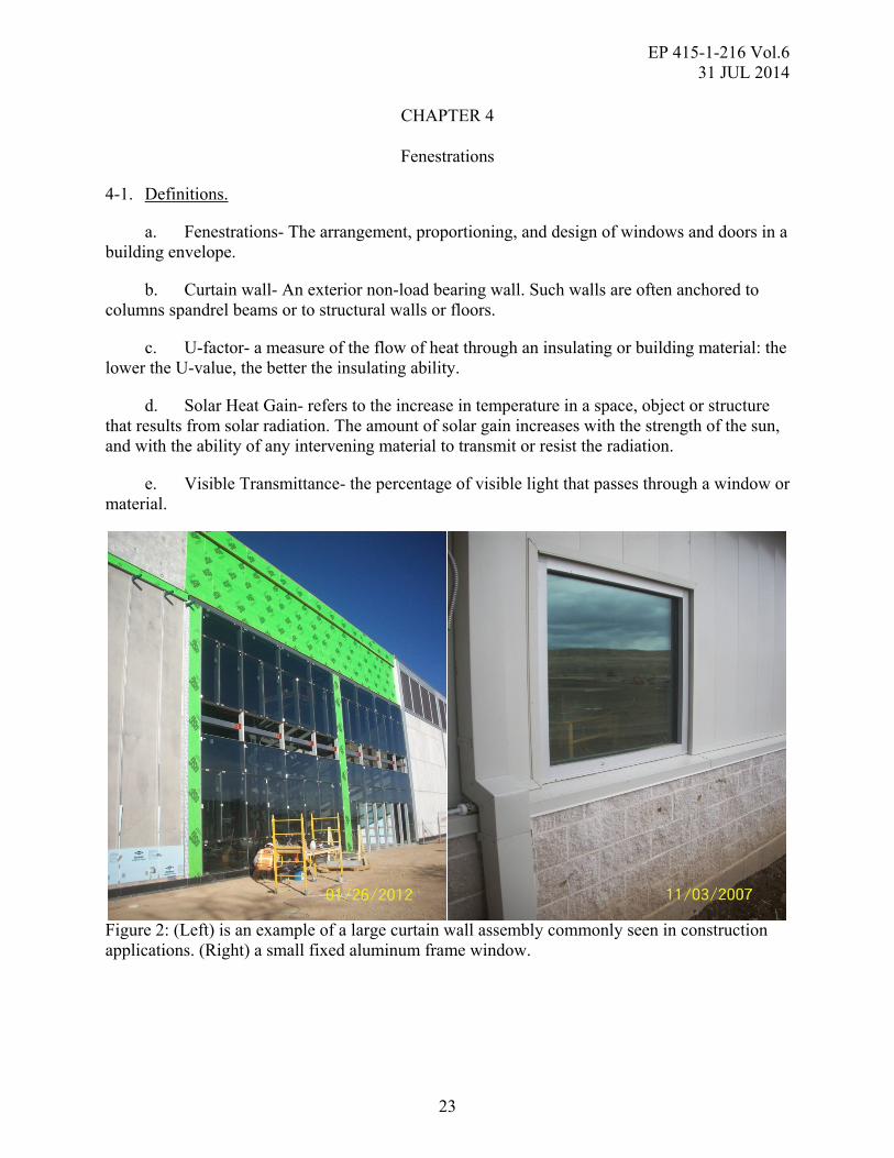
a. Fenestrations- The arrangement, proportioning, and design of windows and doors in a building envelope.
b. Curtain wall- An exterior non-load bearing wall. Such walls are often anchored to columns spandrel beams or to structural walls or floors.
c. U-factor- a measure of the flow of heat through an insulating or building material: the lower the U-value, the better the insulating ability.
d. Solar Heat Gain- refers to the increase in temperature in a space, object or structure that results from solar radiation. The amount of solar gain increases with the strength of the sun, and with the ability of any intervening material to transmit or resist the radiation.
e. Visible Transmittance- the percentage of visible light that passes through a window or material.
Figure 2: (Left) is an example of a large curtain wall assembly commonly seen in construction applications. (Right) a small fixed aluminum frame window.

EP 415-1-216 Vol.6 31 JUL 2014
24
4-2. Materials.
a. The QAR may encounter a variety of fenestration assemblies of different configuration, components and materials. Several of the common materials that may constitute fenestration assemblies and components are:
(1) Aluminum
(2) Steel
(3) PVC
(4) Wood
(5) Fiberglass
(6) Glass
(7) Sealants
(8) Rubber, Nylon, EPDM, Butyl
4-3. Applications.
a. All buildings constructed in the built environment contain fenestrations. It is important for the QAR to understand impacts and interfaces fenestrations have in a high performance building envelope. Because fenestrations have a significant impact on the energy consumption of buildings, application of high performance fenestration assemblies are often designed and modeled with specific properties and expected performance intention. This is particularly important with regard to reduction of thermal bridging. Deviation from the design during construction phase will have a significant impact on the performance of the assembly and the QAR should ensure that the contractor is installing or constructing fenestrations properly in accordance to the contract documents.
b. High performance fenestrations will interface with the other components of the building envelope assembly depending on the wall type. The two critical interface points in the assembly are with the thermal layer and the air/vapor /water control layer. The QAR must ensure that during construction the continuity of both the thermal plane and the air/vapor/water control layer(s) plane with the fenestration assemblies is maintained.
c. The QAR should be aware that weather stripping, gasketing, seals and thresholds are components of fenestrations that directly impact the air leakage and water penetration through these assemblies. These assemblies are considered part of the air barrier plane and need to be sealed. Due to the nature of doors; seals, gaskets and thresholds should be present but leakage will still occur in door assemblies including single, double, sliding, bi-fold, large bay doors of folding, overhead or coiling type.
d. The QAR should be familiar with the common types of fenestrations such as:

EP 415-1-216 Vol.6 31 JUL 2014
25
(1) Curtain wall
(2) Store Front Assemblies
(3) Sky lights
(4) Fiberglass Panels
(5) Fixed or Operable Windows
(6) Doors (coiling, bi-fold, overhead, folding, single, double or sliding)
4-4. QA activities.
a. Contract Document Review
(1) Thermal Layer Continuity
(a) It is important for the QAR to be aware that the placement of the window in the wall effects the thermal value of the assembly. The QAR should be looking to ensure that for windows, the glazing unit of a fixed window assembly is in the same plane as the exterior insulation. Windows that are part of a concrete wall system that has an insulation layer between the two layers of concrete should be placed in that insulation plane.
(2) Interface with the air, vapor and water control layer(s)
(a) The QAR should be aware that the control layer(s) will need to interface with the fenestration assembly and maintain the continuity of the control layer. This interface primarily occurs in the rough opening of a fenestration but could interface directly with a fenestration assembly, such as a window frame for example, designed to accept the control layer directly into the frame of the assembly itself.
(3) Drawings and Specifications
(a) Details
Wall/Roof section call outs
The QAR when reviewing the drawing should be looking for section or detail cuts for the fenestration assemblies to include the head, jamb and sill.
Fenestrations such as roof hatches, skylights or solar tube should be shown in section to identify the assemblies and the interface with control layers.
Detail sheets
The QAR should be looking at the details and ensure that they correspond to the correct fenestration and call out referenced.

EP 415-1-216 Vol.6 31 JUL 2014
26
Details should show the location of the fenestration in the wall assembly with the control layer(s) interface shown. Substrates in the rough opening for thermal bridge reduction purposes or fastening should be shown.
Exterior wall insulation should be shown and should be in the same plane as the glazing of a fenestration. Insulation should be shown to be in contact or nearly in contact with the frame and free from large gaps.
(b) Window, door and fenestration schedules
All window, door or fenestration schedules should be included in the drawing set. The QAR should compare the schedules to the fenestration call outs number in the architectural section of the drawings to ensure that the proper placement of fenestrations corresponds to the schedule.
Fenestration schedules in the drawing set should also be checked by the QAR to the specifications to ensure that the assemblies called out match those specified.
(c) Fenestration callouts by schedule type in the drawings
The QAR should check the drawing set to ensure that the fenestrations are called out in the drawing set and correspond to the schedules as noted.
(d) Specifications
The QAR should be looking for the U-factor, Solar Heat gain coefficient, Visible Transmittance and Air Leakage of fenestrations, specifically windows, curtain walls, storefronts, translucent panel systems and door assemblies. Not all fenestration assemblies will have a U-value, and this should be noted appropriately in the specifications.
The QAR will encounter a variety of glazing types during building construction. The QAR should be looking to ensure that the glazing types have been identified in the specifications and or drawing set and that the performance parameters and criteria are included.
The QAR should also be looking to ensure that the frame types for high performance fenestrations are included in the specifications and their specific performance criteria are included.
b. Three Phase Process
(1) Prepatory
(a) Drawings and Specifications
The QAR should ensure that all of the correct drawings and specifications are present for discussion and review during the prepatory meeting. This includes any specialty drawings or installation instructions for fenestrations such as skylights or solar tubes that may be only generally represented in the contract drawing set.

EP 415-1-216 Vol.6 31 JUL 2014
27
Specifications should be reviewed during the prepatory to identify and project specific requirements and/or installation methods that must be employed during the construction processes.
A careful review of both the drawings and specifications is critical for fenestrations that have been selected and designed to reduce thermal bridges. The QAR and QCM need to ensure that during the prepatory meeting these aspects are discussed and the craftsmen are both familiar and able to construct the assemblies as shown and specified.
(b) Submittals
Material Submittals
High performance fenestration assemblies have been carefully selected for incorporation into the building envelope. The QAR must verify that the materials submitted for construction meet the requirements as outlined in the specifications or drawings. This is particularly important when thermal bridge reduction measures have been specified for fenestration frames and high performance glazing units. Specific aspects of the submittals that must be carefully reviewed and verified against the specifications are; U-factor, Solar Heat gain coefficient, Visible Transmittance and Air Leakage of the particular assembly.
These submittals must be present during the prepatory meeting and reviewed to ensure that any assembly specific information is understood by the craft or trade responsible for fenestration installation. Often common knowledge of fenestration installation is different than that of high performance fenestrations and can alter the overall performance of the assembly once installed.
Shop Drawings
Most fenestration designs are supplemented with manufacturer shop drawings for the field installation. The QAR must review these drawings to ensure that shops are meeting the expectations set forth in both the drawings and specifications as well as match the submittals presented for construction. This includes the interfaces with the control layer(s) and the insulation plane of the wall assembly and any major transitions to other assemblies specific to the project.
(c) Schedule and Sequence
The QAR during the prepatory phase should fully understand the schedule and sequence of installation the contractor intendeds to pursue to construct or install the fenestrations in the building envelope. Verifying that the proper sequence of installation occurs in relationship to other aspects of the building envelope is imperative to ensure that each feature is installed correctly and will meet its specified performance requirements.
The QAR during the prepatory meeting must be aware that the preceding features of work are complete and ready to accept the fenestration assemblies. Work on the fenestration installation should not begin until preceding work is complete.
EP 415-1-216 Vol.6 31 JUL 2014
28
(d) Mock ups
If a mock up is specified in the contact documents, The QAR should ensure that construction of the mock up is performed before the construction of the permanent work begins. The QAR and QCM should both inspect and assess the installation means and methods employed on the mock up are consistent with those expected from the manufacturer of the fenestration and the design in the contract documents.
(e) Testing
All testing of fenestrations should be clearly identified in the contract specifications. During the prepatory meeting the responsibility and time at which the testing is to be performed should be discussed. It should also be discussed weather testing is to be performed on a mock up if specified, or both the mock up and the permanent assembly. Testing of the permanent assembly should be performed as this will be what is expected to perform for the life of the building.
Other tests such as the building envelope pressure test, may not be specifically identified in the specification sections for the fenestrations but are still to be performed on the air control layer/plane which include fenestrations. The QAR should ensure that the contractor and the craftsmen installing the fenestrations are aware of this expectation.
(f) Discrepancies or Changes
Should the QAR discover or be made aware of a change or discrepancy with a fenestration assembly component or the general installation of the fenestration this change should be carefully evaluated before work proceeds. Any changes that alter the design of the fenestration assembly must be evaluated with the COR, ACO or CO and the DOR to ensure contract compliance.
If the assembly is one that is identified and designed for thermal bridge reduction, the change or discrepancy should be evaluated with the DOR and the COR, ACO or CO before work proceeds. This is critical, as small changes in the assembly of a thermal bridge reduction detail can drastically affect the performance of the assembly.
All discrepancies that arise through the construction of the fenestrations should be evaluated by the QAR and the QCM to identify the issue and establish the proper corrective action needed.
(2) Initial
(a) Materials Inspection
All fenestration materials need to be carefully inspected by the QAR to validate compliance to the submittals and the contract documents.
EP 415-1-216 Vol.6 31 JUL 2014
29
Non-compliant or materials that deviate from those submitted should be rejected and removed from the site to avoid accidental incorporation of the materials into the initial sample of the permanent work.
(b) Inspection of Work
The QAR should ensure that all of the craftsmen and the QCM are present for the initial inspection of a fenestration inspection. The inspection should verify that means and methods discussed in the prepatory phase are being employed and that the materials and installation are in accordance to the plans, specifications and submittals.
Inspection points should be reviewed and should any discrepancies, deficiencies or changes be identified they then should be documented and addressed as appropriate.
(3) Follow up
(a) Follow up inspections should be held as necessary to ensure that a consistent and complaint installation of the fenestration assemblies is being performed and that any subsequent issues that may arise in various locations of the building envelope do not cause issue to the installation or expected performance of the assembly.
c. Construction/Installation and Means and Methods
(1) Material Handling-
(a) The QAR should be aware of the manner in which fenestration materials and assemblies are handled during the construction process. Improper handling can result in permanent damage to the material or assembly. Examples of this are improper rigging during hoisting, dragging or sliding material or assemblies, excessive or improper stacking and storage that results in damage.
(b) Materials should not be left in an area that will expose them to environmental damage such as wind, dirt, dust, mud, ice or excessive water exposure. They should be kept in a clean covered area to prevent any environmental related issues.
(c) Safety procedures for material or assembly handling should be addressed in the AHA for the specific application and the QAR should ensure these measures are being implemented.
(2) The QAR may encounter pre-assembled fenestration assemblies on a construction project. These assemblies are generally easy to install and often can be lifted into place and quickly fastened into the rough opening. Often these assemblies may already have all of the needed water resistance and water shedding flashings in place as well. The QAR should however inspect to ensure that the thermal and air/water/vapor control layer(s) are properly interfaced with the assembly and that all water drainage components are installed.
(3) The QAR will often encounter site assembled fenestration assemblies in which all of the component of the assembly are built and installed on site. The QAR should be aware that the site assembled fenestration assemblies are more prone to quality deficiencies than pre assembled

EP 415-1-216 Vol.6 31 JUL 2014
30
ones. Also the increased number of steps involved in installing these fenestrations may involve lifts, cranes, scaffolding or ladders to complete the work and more coordination with other activities will most likely be required.
d. Inspection Points
(1) Ratings and Certifications
(a) The QAR during the materials inspection before initial inspection needs to be looking for all manufacturer labeling or stamps for the appropriate ratings or certifications required of either the frame or glazing.
(b) Frame and Glazing performance ratings for a fenestration are a specific inspection point for the QAR before the work has begun on installation. When inspecting these labels the QAR should be looking for the following: U-factor, Solar Heat gain coefficient, Visible Transmittance and Air Leakage. This is commonly a large white adhesive label adhered to a glazing unit or could be included in a submittal from the NFRC (National Fenestration Rating Council). These performance criteria should be back-checked with the specifications to ensure that the proper fenestration assembly is present on site. http://www.nfrc.org/WindowRatings/The-NFRC-Label.html
(2) Rough opening-
(a) The QAR should inspect the rough opening of the fenestration on the wall prior to the installation and after installation of the fenestration to ensure that the control layers are present and complete and that the substrate is ready to accept the fenestration. Should any incomplete or damaged material be present in the rough opening it should be completed or repair prior to fenestration installation.
(3) Frame attachment to the rough opening
(a) In high performance fenestration applications the correct installation of the fenestration frame is critical. The QAR should be looking to ensure that the frames are fastened in the correct locations and that the substrate material can accept the fastener. Control layer material should be such that the installation of fasteners dose not deter from the control layer performance. Fasteners should be fully set and any loose fasteners tightened. If noted in the drawings or the shop drawings any sealant beds should be placed before the frame is installed.
(4) Thermal Layer Continuity
(a) The QAR should be ensuring that the fenestrations are being placed in the insulation plane of the wall roof assembly. It is a common deviation found during window installation that the drawings show the correct configuration but the installation is incorrect. It is critical that the placement be correct due to the fenestration having a thermal effect on the performance of the building envelope as a whole. This is particularly critical on fenestrations that have been designed to reduce thermal bridging.
(5) Frames

EP 415-1-216 Vol.6 31 JUL 2014
31
(a) The QAR should be looking first, upon material inspection, that the correct frames have been received as specified and shown in the drawings.
(b) The QAR should inspect fenestration frames before incorporation into the final work to ensure they are free from any damage that may have occurred from transport or material handling. Common damage includes: dents, bends, broken frame rails, scratches, distortion or issues with the square of the frame and color of the frames. Size and dimension should also be checked to ensure that windows will fit in the rough opening.
(6) Glazing units
(a) The QAR should closely inspect glazing units when they arrive on the site and during the installation process. Glazing units are subject to damage easily during handling and transport. Common damage seen in glazing units include: chips, cracks, damaged seals, bent spacers, scratches and paint or markings which cannot be removed.
(b) Orientation of the glazing unit is a critical point that the QAR must ensure is done properly. Often the exterior pane of glass in a glazing unit has different properties than the inner and ensuring that that exterior pane is on the exterior is critical to the performance of the assembly. Glazing manufactures will often identify which side is interior and which side is exterior. If there is confusion, contacting the manufacturer will help prevent any improperly oriented glazing and the rework associated with this deficiency.
(c) Glazing seals and sealant materials need to be inspected prior to installation. Many glazing units are filled with gasses to increase the U-value of the glazing. If the seal is damaged the gas will escape and the window will eventually condensate between the panes of glass. Common deficiencies with glazing unit seals are; separation of the sealant from the glass, cuts tears or holes in the sealant bed or incomplete sealant application.
(7) Weather Sealing
(a) Weather sealing of the fenestration assemblies is also important for the QAR to inspect thoroughly. Weather sealing and the materials that perform this function in various locations within the assembly. Due to the wide variation in fenestration types the general locations for weather sealing include exterior and interior frame to glass, frame to wall and internal seals around glazing. It is important that these seals be continuous and that the QAR inspect these seals periodically throughout installation. Once seals are in place they should be inspected for any separation, holes or discontinuities, cuts or gaps or any areas that failed to set up correctly. Butyl tapes or similar materials should be checked for fish mouths, gaps or areas that failed to adhere.
(b) Weather sealing should not be placed in window frames that have intentional weeps of water drains. The QAR should be looking to ensure that the craft do not accidentally seal in these areas.
(8) Flashings
EP 415-1-216 Vol.6 31 JUL 2014
32
(a) Flashings are a critical feature of the window that will shed water and prevent intrusion into the wall cavity or interior space. The QAR should inspect all flashing materials around the fenestration particularly at the head and sill. Flashing materials should slope slightly to the exterior to drain water that comes in contact. Joints in flashing materials should be sealed and all flashings should be well fastened or adhered to the substrate.
(9) Square and Installation
(a) The square and installation of fenestrations is an aspect that the QAR should inspect carefully. Out of square fenestrations may improperly take load during expansion or contraction and cause the glazing unit to crack or fail as well as the frame to fail. The QAR should inspect the square of the fenestrations with a short level to verify the square of the assembly.
(b) The QAR should inspect the rough opening to ensure that the opening is sized properly to accept the fenestration. Rough openings that are not sized with some clearance, roughly a 1/4-1/2 inch, for the fenestration may cause the fenestration itself to be difficult to install or over time with movement fail. The rough opening should not be excessively larger that the fenestration assembly as this may cause the fenestration to become difficult to fasten into the opening and cause large gaps around the fenestration. This can often affect the aesthetics of the exterior and the functionality of the fenestration when interfaced to the control layer(s) to resist air, vapor and water.
(10) Interface with control layers.
(a) Fenestrations are a major part of the whole building envelope and are expected to perform as air, vapor and water barrier assemblies. Fenestrations will interface with the air/vapor and water control layers in various ways depending wall type and control layer type. The QAR should be looking for the several common elements of the control layer fenestration interface.
For most wall types the common application for control layer interface into the rough opening is with a flexible self adhered membrane. This application applies to all types of control layer materials. The window sealant from the frame to the membrane will be the control layer interface. Depending on fenestration type this interface should be located inboard of any drain or weep system a fenestration assembly might have.
For spray polyurethane foam applications, this flexible self adhered membrane will need to transition from the rough opening and make contact with the foam around the opening. The fenestration will then interface with the sealant in the same manner as above.
With some fenestration assemblies, the frame or mullion may have a special interface location with the control layer. The QAR should be aware that if the fenestrations specified have this feature that the craft installing the fenestration are also aware and do not improperly install the assembly.
e. Special Inspections and Testing
(1) The QAR should be familiar with any Building Envelope Commissioning (BECx) related testing that may be specified for fenestration assemblies. Water leakage testing and

EP 415-1-216 Vol.6 31 JUL 2014
33
assembly specific air leakage testing are two common BECx tests. These tests are most often ASTM E 783- Standard Test Method for Field Measurement of Air Leakage Through Installed Exterior Windows and Doors and ASTM E 1105- Standard Test Method for Field Determination of Water Penetration of Installed Exterior Windows, Skylights, Doors, and Curtain Walls by uniform or Cyclic Static Air Pressure Difference.
(2) It is important for the QAR to be aware that the test performed under ASTM E 783 is not the same as the building envelope pressurization test as defined by ASTM E 779 and does not abrogate the building envelope pressurization testing requirement.
f. Documentation
(1) The QAR should document any field inspection activities performed to include testing, daily inspection, or the three phase inspection process performed for this feature in the daily report for the project.
(2) The QAR should collect any manufacturer site visits or inspection notes during the construction process from the QCM and document these in the contract file.
(3) The QAR should take photos of the work periodically and photographically document any deficiencies found during the inspection process.
(4) The QAR should collect or have submitted all fenestration related inspection or test reports from the QCM and document them in the contract file.

EP 415-1-216 Vol.6 31 JUL 2014
34
THIS PAGE INTENTIONALLY LEFT BLANK
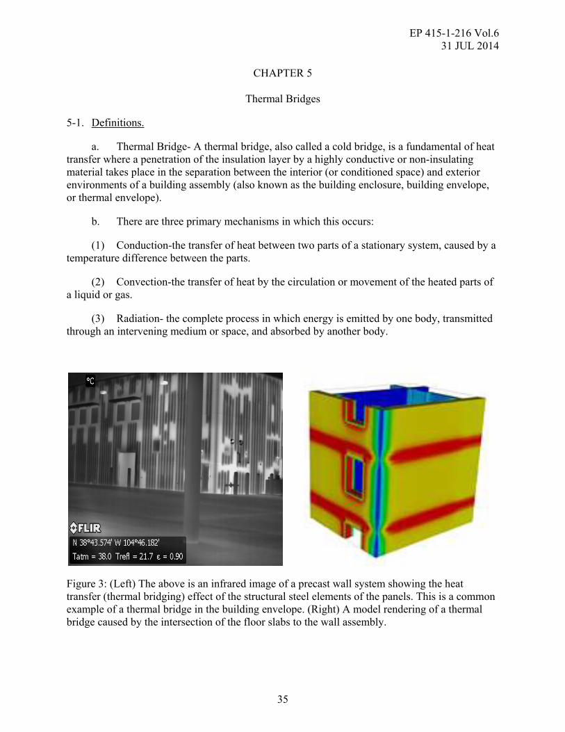
EP 415-1-216 Vol.6 31 JUL 2014
35
CHAPTER 5
Thermal Bridges
5-1. Definitions.
a. Thermal Bridge- A thermal bridge, also called a cold bridge, is a fundamental of heat transfer where a penetration of the insulation layer by a highly conductive or non-insulating material takes place in the separation between the interior (or conditioned space) and exterior environments of a building assembly (also known as the building enclosure, building envelope, or thermal envelope).
b. There are three primary mechanisms in which this occurs:
(1) Conduction-the transfer of heat between two parts of a stationary system, caused by a temperature difference between the parts.
(2) Convection-the transfer of heat by the circulation or movement of the heated parts of a liquid or gas.
(3) Radiation- the complete process in which energy is emitted by one body, transmitted through an intervening medium or space, and absorbed by another body.
Figure 3: (Left) The above is an infrared image of a precast wall system showing the heat transfer (thermal bridging) effect of the structural steel elements of the panels. This is a common example of a thermal bridge in the building envelope. (Right) A model rendering of a thermal bridge caused by the intersection of the floor slabs to the wall assembly.
EP 415-1-216 Vol.6 31 JUL 2014
36
5-2. Materials.
a. Common materials used in the construction of buildings all conduct heat. The ability for these materials to transmit this heat through the building envelope is what’s most important for a QAR.
(1) Metals such a steel, aluminum, copper, ductile iron, concrete, masonry, glass and air transmit heat at a much faster rate compared to woods, plastics, fiberglass, foam board, SPF that do not transmit heat as rapidly.
5-3. Applications.
a. Configuration(s) of the various building elements through, outside of, or that bypass the building envelope thermal layer are common locations for thermal bridges. The goal is to slow or eliminate the heat flow through these building elements. Designers and researchers are working continuously to develop these new configurations. The QAR must be aware that ongoing research and development on the means and methods to reduce thermal bridges is going to require new variations of common building assemblies.
b. Designers that have chosen to incorporate thermal bridge reduction measures have gone through an extensive modeling and design process to ensure that the assemblies and components of the building envelope are maximally reducing the amount of energy lost from a thermal bridge. It is critical for the QAR to ensure that the construction of these particular areas is strictly compliant with the designed details.
c. Thermal bridges depending on their location and the materials have a major effect on the energy consumption of a building. The greater the conductivity of the material coupled with the configuration of the assembly can lead to a location or series of locations in a building envelope that cause energy loss to the conditioned space.
d. Common building elements that may create thermal bridges:
(1) Building Structure
(a) Structural Steel
(b) Concrete
(c) Masonry
(2) Fenestrations
(a) Curtain wall
(b) Store front Assemblies
(c) Sky lights/Solar tubes
(d) Translucent Wall Panel Systems
EP 415-1-216 Vol.6 31 JUL 2014
37
(e) Windows
(f) Doors
(3) Building Features
(a) Slabs ( elevated or on grade)
(b) Decks
(c) Awnings
(d) Penetrations (HVAC, mechanical, utilities, fire service, roof drainage)
(e) Soil
(f) Concrete
(g) CMU/Block/Brick
5-4. QA activities.
a. Contract Document Review
(1) Drawings and Specifications
(a) The QAR during the contract document review process needs to be aware that the project is going to employ the measures to reduce thermal bridging. From this basis this QAR should be looking into the drawings and details to ensure that locations and details for these specific areas are noted or identified as thermal bridge reduction/elimination locations.
(b) These locations may span multiple sections of the drawing set but should still be clearly identified.
(2) Details
(a) Details should be drawn for the identified locations and the QAR should be looking for these within each specific section of the drawings to assure that they match to the section they relate to and are simply present in the set for construction.
(b) Interface with the air water and vapor control layers and the thermal insulation layer are also aspects that the QAR should be looking for, particularly around penetrations of all types and fenestrations.
b. Three Phase Process
(1) Prepatory

EP 415-1-216 Vol.6 31 JUL 2014
38
(a) Thermal bridges can occur in many different assemblies or components of the building. This may lead to the need to identify and subsequently discuss any feature specific locations that will be built specific to the feature beginning construction. The QAR, QCM and craft constructing the feature will need to carefully review the drawings for these locations during the prepatory and discuss how they will be properly constructed.
(b) The QAR must enforce the fact that deviations from the proposed design as well as poor quality construction can negatively impact the performance of thermal bridge reduction components. All deviations or field construction means and methods that could affect the performance must be verified by the DOR prior to completion of the work. The Contracting Officer should be made aware of any proposed changes prior to or before the work is completed.
(c) Discrepancies or changes
Should the QAR discover or be made aware of a change or discrepancy with thermal bridge reduction location or the general installation or application of the measures to reduce the thermal bridge, this change should be carefully evaluated before work proceeds. Any changes that alter the design of the fenestration assembly must be evaluated with the COR, ACO or CO and the DOR to ensure contract compliance.
(2) Initial
(a) Materials Inspection
The QAR must inspect the materials on hand that will be used in the assembly or in the component of the building that is designed to reduce thermal bridging. This is more important due to the fact that variations in materials alter the designed performance of the assembly or component.
(b) Inspection of Work
At the initial inspection the QAR needs to assure that the assembly or component has been assembled as designed. Any unaccounted for variables that may have arisen during the construction need to be addressed and if at this point, the construction of these assemblies or components is not possible in the current design, then the DOR must be approached for an alternative solution.
(3) Follow up
(a) The QAR must assure that the QCM and the Craft are replicating the established quality in follow on work. This is of particular importance given that thermal bridges are often repetitive in the assembly or component and that the successful installation of these assemblies or components improves the overall reduction in energy consumption.
c. Construction/Installation and Means and Methods
EP 415-1-216 Vol.6 31 JUL 2014
39
The QAR should assure that the means and methods are appropriate for the given location and construction of the feature. Due to the variability of these particular assemblies, means and methods should ultimately produce the designed assembly or components.
d. Inspection Points
(1) Damage or alteration
(a) Any damage that occurs to a material, assembly or component should be inspected and the damaged material removed and replaced before and subsequent work is completed.
(b) Materials that have been altered by the installing craft or by craft installing or constructing follow on work need to be inspected and evaluated. These alterations must be identified and relayed to the DOR for evaluation before completion of the work.
(2) Interface and continuity with the air, water and vapor control layers as well as the thermal envelope as they relate to a particular thermal bridge detail. This may vary given the location of a particular thermal bridge.
(3) Material Storage
(a) All materials that are to be used in the thermal bridge reduction components or assemblies should be stored out of any adverse weather conditions and to prevent any accidental damage.
e. Special Inspections and Testing
(1) There is currently no accepted means of testing a thermal bridge for performance in the field.
f. Documentation
(1) The QAR should document any field inspection activities performed to include testing, thermal inspection, daily inspection, or the three phase inspection process performed for this feature in the daily report for the project.
(2) The QAR should collect any manufacturer site visits or inspection notes during the construction process from the QCM and document these in the contract file.
(3) The QAR should take photos of the work periodically and photographically document any deficiencies found during the inspection process.
(4) The QAR should collect or have submitted all thermal bridge related test reports from the QCM and document them in the contract file.

EP 415-1-216 Vol.6 31 JUL 2014
40
THIS PAGE INTENTIONALLY LEFT BLANK

EP 415-1-216 Vol.6 31 JUL 2014
41
CHAPTER 6
Thermal Envelope and Insulation
6-1. Definitions.
a. Insulate - to cover, line, or separate with a material that prevents or reduces the passage, transfer, or leakage of heat.
b. Thermal Envelope - The insulating layer on the exterior of the building envelope that resists heat flow between the interior conditioned space and exterior climate.
c. R-value - a measure of resistance to the flow of heat through a given thickness of a material (as insulation) with higher numbers indicating better insulating properties.
d. U-value - a measure of the heat transmission through a building part (as a wall or window) or a given thickness of a material (as insulation) with lower numbers indicating better insulating properties.
6-2. Materials.
a. Boardstock Materials
(1) Polyisocyanurate
(2) Expanded polyurethane
(3) Extruded Polyurethane
b. Spray Applied Polyurethane Foams
(1) Closed Cell (High, Medium and Low Density)
(2) Open Cell (High, Medium and Low Density)
c. Fiberglass Insulation Products
(1) Roll stock
(2) Loose Fill
d. Recycled Cellulose blocks or Loose Fill
e. Mineral Fiber Insulation blocks or boards

EP 415-1-216 Vol.6 31 JUL 2014
42
Figure 4: (Left) This installation of the exterior insulation board in this figure is of high quality. Note the boards and joints between them are tight with no large gaps present. Brick ties shown in this installation to are not interfering with the continuity of the insulation and are actually designed to double as fasteners for the insulation boards to the substrate. (Right) An example of a closed cell spray foam insulation material.
6-3. Applications:
a. The primary application of insulation materials installed to the six sided building envelope is to prevent heat (energy) loss between the conditioned space to the exterior climate. Nearly all modern buildings employ an insulation layer to the building envelope, the value of which is determined by climate.
b. Location of the insulation layer and the thickness of the layer are contingent on the location and local climate of the building as well as the wall type. Most common in high performance building envelopes the insulation with be on the exterior of the building and /or the interior cavity of the wall. Material applications will vary between wall types however most commonly boardstock materials will be located on the exterior of the wall assembly. In some applications the use of spray applied foams can be used on the exterior of the building concealed behind and exterior cladding or rain screen. Spray applied foams will most often be located on the interior side of the wall assembly with the occasional exception for application to the exterior side. Nearly all of the applications for fiberglass or mineral fiber insulation products in a non-residential application will be located on the interior side of the wall assembly. Fiber and cellulose type products are highly hydroscopic and do not perform in a location that has exposure to moisture such as the exterior side of a wall assembly.
6-4. QA activities.
a. Contract Document Review

EP 415-1-216 Vol.6 31 JUL 2014
43
(1) The QAR during the document review process should be looking to identify the insulation plane and overall thermal envelope of the building. The QAR should also identify that the thermal envelope is continuous over the six sides of the building envelop.
(2) The QAR should, when reviewing the drawing set, looking to ensure that all of the materials are properly identified in the wall and roof sections of the drawing set. Thicknesses and locations should be noted for proper installation during construction.
(3) When reviewing the specifications the QAR should be looking to ensure that the materials called out the wall or roof sections of the drawing set correspond to those specified in the specifications.
b. Prepatory Requirements
(1) Drawings and Specifications
(a) During review of the drawings and specifications for installation or application of the thermal insulation, the QAR should ensure that proper craftsmen or sub-contractors are present and are familiar with the materials to be used for the thermal layer.
(b) Locations and proper application of the materials shown should be discussed to ensure a quality application or installation is achieved. Details should be reviewed to ensure the interface with the various other aspects of the envelope, such as the control layers and flashings are properly constructed.
(c) Specifications must be reviewed and parameters of the materials to be used identified and clearly discussed to prevent failure of a material or the mis-application or installation of the material.
(2) Submittals
(a) Material Submittals
The QAR should review and be familiar with the submittals associated with the insulation products specified. Ancillary submittals such as brick ties, clips and fasteners should also be reviewed for compatibility with the exterior insulation to ensure that a continuous plane of insulation is achieved.
Type(s) and thicknesses of insulation materials should be verified by the QAR on the submittals to ensure that the proper materials have been submitted for use on the project.
(b) Shop Drawings
There are generally no shop drawings associated with the installation or application of insulation materials.
(3) Schedule and Sequence

EP 415-1-216 Vol.6 31 JUL 2014
44
(a) The QAR should verify that the substrates and preceding work, such as control layers and flashings are complete and the assemblies are in a condition to receive the insulation materials.
(b) For interior applications of insulation, all wall close in inspections should be complete prior to insulation be applied or installed in the interior cavity to verify that all preceding work is complete and properly installed.
(4) Mock ups
(a) Installation or application of insulation materials should be performed on the mock-up as specified, prior to the permanent work beginning
(b) The QAR should with the QCM and craftsmen inspect and evaluate the installation or application of the insulation materials for compliance to the manufactures instructions and the project specifications. Installation of fasteners, clips and brick ties should be in place as well to verify the installation of these components with the insulation materials primarily for an exterior application or installation.
(5) Testing
(a) The QAR should be familiar with testing requirements for the thermal envelope as specified in the contract documents.
(6) Discrepancies or Changes
(a) Should the QAR discover or be made aware of a change or discrepancy with the insulation material or the general installation or application of the insulation layer, this change should be carefully evaluated before work proceeds. Any changes that alter the design of the fenestration assembly must be evaluated with the COR, ACO or CO and the DOR to ensure contract compliance.
c. Initial
(1) Material Inspections
(a) All materials for the installation or application of the insulation should be inspected prior to its installation or application into the permanent work. Materials should be verified against the submittals and specifications and any noncompliant materials should be separated and removed from the site to prevent accidental incorporation in the feature of work.
(2) Inspection of Work
(a) All work should be inspected with the QCM and craftsmen present to assure that work is proceeding correctly and in conformance to the contract documents.
(b) If a mock up is specified, application or installation means and methods gleaned or validated on the mock-up should be continued on the permanent work.

EP 415-1-216 Vol.6 31 JUL 2014
45
d. Follow up
(1) Follow up inspections should be performed periodically throughout the installation or application process to assure that work is proceeding as expected and the address and discrepancies, changes or deficiencies that may arise during the construction process.
e. Construction/Installation and Means and Methods
(1) Installation means and methods for boardstock materials are fairly simple as most boardstock materials are pre-sized boards that are supplied to the site in large bundles. Most often full boards are mechanically fastened to the substrate or held in place by brick ties that are uniquely designed to support insulation boards. In some instances the boards can be adhered to the substrate contingent upon the substrates ability to accept an application of adhesive without detriment to the performance of the substrate material. Some cutting of the boards may be needed to fit to the dimension of the building. Depending on wall height and type insulation board installation work may require the use of lifts and the appropriate safety measures need to be addressed in the feature of work AHA.
(2) Installation of spray applied foam products either to the interior or exterior of the wall assembly will require more coordination between the various trades and craft working on other features of the building. Due to the nature of spray applied products, environmental conditions required by the manufacturer for application must be met in order for the material to perform as desired. This may include heating or cooling a space, ventilating a space from off gassing of the foam application, protecting substrates from environmental exposure such as moisture or debris, providing designated work areas free from other trades or craft during the application and providing protection form detrimental exposure to sunlight in exterior applications. Proper PPE must be worn including respiratory protection, skin protection and face shield during the application spray applied foams due to the off gassing and particulate material. Access to areas may require lifts and all appropriate safety measures for the use of lifts should be outlined in the feature of work AHA.
(3) The installation of fiber or cellulose rolls or loose fill materials should generally be performed when all of the other work has been completed in the interior wall cavity. Common fiber glass roll insulation materials come to the site in large sealed rolls that can easily be cut to fit to a desired length. The rolls should be secured either by mechanical fastening, adhesive tapes or as specified by the manufacturers product literature. Loose fill materials, both fiberglass and cellulose are most commonly blown into a cavity or space via a hose and specialized machine. The QAR should ensure that the proper PPE is being utilized for handling fiber product and the fiberglass and mineral fiber products specifically as they can cause skin irritation. These procedures should be outlined in the feature of work AHA.
f. Inspection Points
(1) Fastening- all fasteners used to mechanically fasten sheet materials to the substrate and brick-ties, clips or other types of fasteners should be gasketed or sealed if they penetrate the air, water vapor control layer and specifically for air leakage prevention.

EP 415-1-216 Vol.6 31 JUL 2014
46
(2) Holes made by incorrect placement of fasteners that are removed should be resealed in accordance with the methods appropriate to the material being used.
(3) Gaps, Cracks and Joints-The QAR when inspecting the installation of a boardstock insulation material application should be inspecting for any gaps between the material and the substrate. Large gaps or space in this location can reduce the performance of the insulation layer by allowing air to bypass the insulation. This is also to be avoided in joints between the boards and around brick ties, fenestrations and penetrations. In spray foam applications the QAR should be looking for any cracking that has developed in the foam. This primarily occurs in rigid closed cell foams used for both insulation and the air barrier. These cracks tend to develop in locations that are subject to movement either expected or unexpected and if found should be evaluated. If in an unexpected location the DOR should be contacted to evaluate the issue. If in an expected location then the installation or application should be evaluated and modified with the appropriate flexible transitions to prevent the cracking.
(4) Continuity- The QAR should be inspecting the insulation layer for continuity and conformance to the plans and specifications. Continuity in the insulation plane impacts the overall energy performance of the thermal envelope and is critical around fenestrations, penetrations and in thermal bridge reduction locations.
(5) In the application of roll stock fiber materials in the interior cavity space the QAR should be inspecting for sagging or folding of length of the material as well and full depth installation of the materials. Sagging, folding or material that is not the correct depth for the cavity it is being installed in will reduce the thermal performance of the insulation. Material that is not properly fastened may exhibit these issues and the QAR should identify any of these areas before the wall is closed in.
(6) Complete filling of the space in which a loose fill fiber material is being installed is a point that the QAR should be inspecting during the installation of the material. Voids in the filled material or the incorrect depth of fill in a horizontal application affect the performance of the thermal layer and should be identified and corrected before completion of the work.
(7) Storage of insulation materials is a critical point of inspection for the QAR to perform. Fibrous or cellulose insulation products are sensitive to moisture and will take on moisture if exposed to it. All insulation materials should be stored in a dry location free from exposure to dirt dust and debris.
(8) Damage to insulation materials should be avoided and if damaged materials are found during inspection by the QAR they should be removed and replaced. Common damage to insulation products includes: Sticking tools into the material, damage from lifts or other construction equipment, burning or melting from welding, brazing or cutting operations, foot traffic, poor cutting or material manipulation and material handling.
(9) Application parameters specifically for spray applied foams should be closely monitored by the QAR. Application temperatures, substrate temperatures, proper mixing and mixing temperatures of components and thickness should all be evaluated when inspecting and observing the application of the material. Common application issues with spray applied foams can be; failure of the material to set up leaving a soft wet material in the applied area, failure to
EP 415-1-216 Vol.6 31 JUL 2014
47
expand due to improper application or mixing temperatures, failure to adhere to the substrate due to dust, debris or a substrate that cannot accept the foam, improper thickness of material and poorly maintained application equipment. The QAR should be aware that in a spray foam application the application may not be perfectly uniform on the surface. This is acceptable as long as there is no more or less than ½ inch in the variation.
(10) Environmental protection of insulation materials is critical for the QAR to ensure the contractor performs. Protection of exterior applications of spray applied foams from sunlight exposure is critical as the material will degrade quickly when exposed to sunlight for even short amounts of time. Protection of fibrous insulation materials from exposure to moisture is critical. Fibrous insulation material should not be installed if is wet or has been or could potentially become wet. These materials will hold significant amounts of water and if installed may not dry sufficiently to prevent mold mildew or other moisture related problems from occurring in the assembly. This also applies to open cell spray foam applications as this material has no resistance to moisture like the closed cell materials do.
(11) It is important for the QAR during the inspection process to ensure that if foam applications in window and door frames are used that these foams are open cell and low to medium density. Closed cell foams used in this application can cause distortion or damage to the frame during the curing of the material. Should the QA encounter this condition in the field, the work should be removed and replaced with a new assembly.
g. Special Inspections and Testing
(1) Thermal Imaging- If specified in the contract documents, thermal imaging and inspection of the thermal envelop may be required. This requirement may be required to validate the continuity of the thermal envelope. The QAR should be present when this testing is performed to document the location in which deficiencies are found.
(2) Periodic testing of the thickness of a spray foam application should be performed by the QAR during the application of the material to verify the application thicness is correct.
h. Documentation
(1) The QAR should document any field inspection activities performed to include testing, thermal inspection, daily inspection, or the three phase inspection process performed for this feature in the daily report for the project.
(2) The QAR should collect any manufacturer site visits or inspection notes during the construction process from the QCM and document these in the contract file.
(3) The QAR should take photos of the work periodically and photographically document any deficiencies found during the inspection process.
(4) The QAR should collect or have submitted all insulation related test reports from the QCM and document them in the contract file.

EP 415-1-216 Vol.6 31 JUL 2014
48
THIS PAGE INTENTIONALLY LEFT BLANK

EP 415-1-216 Vol.6 31 JUL 2014
49
CHAPTER 7
Air, Vapor and Water Control Layers
7-1. Definitions:
a. Control layer(s) - The layers or planes of continuous material in the building envelope that separate the exterior climate, specifically air, water, water vapor and heat from the interior conditioned space. (Note: The thermal envelope falls under this definition but is covered exclusively from this section in a separate section.)
b. Air Barrier: Air barriers are systems of materials designed and constructed to control airflow between the conditioned space and unconditioned space.
(1) An air barrier material is specifically defined as a material that has an air permeance less than or equal to .004 cfm/ft2 at 1.57 lb/ft2 or .02 (L/s)/m2 at 75 Pa per ASTM E 2178.
c. Vapor Retarder: A material or system of materials which adequately retard the transmission of water vapor under specified conditions.
(1) Vapor barrier/retarder is specifically defined into three general categories.
(a) Class I = 0.1 perm or less
(b) Class II = 0.1 < perm ≤ 1.0 perm
(c) Class III = 1.0 < perm ≤ 10 perm
d. Water Resistive Barrier: A material behind a exterior wall covering that is intended to resist liquid water that has penetrated behind the exterior wall covering from further intruding into the exterior wall assembly.
7-2. Materials:
a. Air Barrier: Air barrier products come in a variety of forms and materials each having its unique properties and requirements. These materials generally fall into the following categories:
(1) Mechanically Fastened Sheet Films (Building Wraps)
(2) Spray Polyurethane Foams (closed cell)
(3) Self Adhered Sheet Membranes (Ice and Water Shield)
(4) Fluid Applied Membranes
(5) Accessories- Flashings, Tapes, Sealants, Specialty Fasteners, bridging materials.

EP 415-1-216 Vol.6 31 JUL 2014
50
(6) Boardstock Materials ( Foam boards, Exterior Sheathing Materials and gypsum board in select interior cases)
(7) Concrete
(8) A fully sealed primary waterproofing layer of a roof system (such as flexible self adhered ice and water shield type product or a fully adhered membrane of a membrane roof system).
b. Vapor Retarder
(1) Class I: Sheet polyethylene or non-perforated aluminum foil.
(2) Class II: Kraft Faced fiberglass batts.
(3) Class III: Latex or enamel paint.
c. Water Resistive Barrier
(1) Bituminous liquid applied coatings
(2) Bitumen impregnated felt or building papers.
(3) Mechanically Fastened Sheet Films (Building Wraps)
(4) Fluid Applied Membranes
(5) Self Adhered Sheet Membranes (Ice and Water Shield)
(6) Spray Polyurethane Foams (closed cell)

EP 415-1-216 Vol.6 31 JUL 2014
51
Figure 5: These are examples of the four most common air water and vapor control layer materials. (Top) A fluid applied membrane material and a self adhered membrane functioning as the thru-wall flashing at the mud-sill. (Bottom left) A common mechanically fastened sheet film building wrap product. (Bottom Right) A cut out section of a closed cell spray applied foam applied to the interior cavity of the exterior wall assembly.
7-3. Applications:
a. In the applications or incorporation of these materials into a construction project it is important to understand that these classifications of materials can be installed or incorporated into the construction project individually to perform the intended function but are most often in the wall assembly as one material that functions in all three roles on the exterior side of the wall

EP 415-1-216 Vol.6 31 JUL 2014
52
or roof assembly. This primarily depends on the wall type, the materials that are being incorporated into wall or roof assembly and climate in which the project is being constructed. In concrete wall systems such as precast, tilt up and insulated concrete forms the concrete itself will be acting as the air, vapor and water resistive barrier.
b. The importance of establishing a single air/vapor and water plane in a high performance building envelope and avoiding double barrier conditions is paramount.
c. It is critical that the contractor fully understand that the project scope includes the installation and performance testing of the air barrier system and that this system is continuous within all 6 sides of the building envelope.
d. It may occur that the air barrier system may be compartmentalizing a segregated space within the greater building envelope or joined into the main exterior envelope from the interior. The contractor must be aware of this configuration and not place work that could be detrimental or impede the installation or continuity of the air barrier system.
e. Vapor barriers are materials that intentionally placed in a wall assembly to prevent the migration of water vapor in to the wall assembly. These are only selectively incorporated in to wall assemblies at the Class I or Class II perm rating in certain circumstances on the interior side on the wall assembly
f. Water resistive layers in wall types other that tilt-up and precast concrete will be located on the exterior side of the wall and roof assembly to resist and drain away water introduced by the exterior environment.
7-4. QA Activities.
a. Contract Document Review
(1) Layer Placement and Continuity
(a) During the contract drawing review process the QAR should be looking for key barrier placement in the exterior wall assembly. This placement is highly important to the long term health and performance of the building envelope and will vary with wall type. Material application and hygro-thermal behavior of the wall system drives the placement of the barrier. Mechanically fastened sheet films, fluid applied membranes and self adhered membranes should applied in the exterior wall assembly to the exterior sheathing and under the exterior insulation layer in a common stud cavity wall. At this location the material will be acting as an air barrier, vapor barrier and water resistive layer. This holds true for wall types that have an uncoupled exterior façade such as brick, metal panel or other similar system as well as exterior insulation and finish systems (EFIS).
(b) Closed-cell spray applied foams are most often applied to the interior cavity space of the wall and underside of a roof assembly and will act as both insulation, air barrier and vapor retarder. A water resistive layer will still need to be applied to the exterior sheathing and the roof assembly to prevent water intrusion. In the application of SPF to the exterior of the assembly it is

EP 415-1-216 Vol.6 31 JUL 2014
53
important that this material be a closed-cell foam and be a product with the properties required for exterior application.
(c) The QAR should also be looking for continuity of the system at the common locations in the drawing set. These include foundation to wall, wall to roof, within the roof, and interface with all fenestrations, penetrations, parapets and around soffits and eaves. Details of these common locations should be included in the drawing set.
(d) The QAR should be looking for any double barrier conditions that may be shown in the drawings. Double barriers can cause detrimental moisture conditions in a high performance wall assembly. In most building applications with the air/water/vapor barrier is located on the exterior of the substrate and under the exterior insulation. There should not be anything more than a Class III vapor barrier inboard of this plane in the wall system, except in certain circumstances.
(e) In many instances rooms or portions of a building may be compartmentalized specifically as part of the air barrier system to segregate spaces within the greater envelope. These areas should be shown and the components of these assemblies identified within the drawing set with wall sections and details.
(2) Drawings, Specifications and Details
(a) Drawings
The drawing set should clearly indicate the control layer(s) as either separate notes identifying those components or as the combined function layer as applicable.
Specific to the air barrier layer, the drawings should contain a sheet or sheets, as applicable, identifying the extents and location of the air barrier system. On the sheets included in the set defining the air barrier system, the air barrier system should be able to be continuously traced in the envelope. This should both be in plan and in section because often there are compartmentalized areas or multiple floors that may need to be specifically identified.
Also specific to the air barrier system, the drawings should contain the envelope testing surface area values for use during the performance testing of the air barrier system.
(b) Material Specifications
Each project may incorporate one or several types of these materials into a project based on the size, function and complexity of the project. During specification review the QAR should be looking to ensure that materials specified meet the set performance requirements for that product or function and are compatible with substrates and performance expectations.
There should be continuity with the materials identified in the drawing sheets and the materials specified in the project specifications.
If installer certifications are required it should be identified as a submittal item to validate these credentials.
EP 415-1-216 Vol.6 31 JUL 2014
54
The QAR should be diligent to verify if any type of mock up requirements have been specified by the designers. Mock ups are often very useful in identifying envelope assembly issues before they have been constructed in the permanent work. Inclusion of mock up requirements is encouraged and depending on the project may be required.
(3) Prepatory
(a) Drawings and Specifications
The QAR should assure that the correct drawings and specifications are being used during the meeting and that all applicable sheets needed for the scope are available.
The QAR should ensure that all details and drawings are discussed and reviewed by the Craft and the QCM to ensure that there is no confusion about the scope of the work or the locations in which the control layer(s) will be placed.
Any required tests for project specific specification requirements need to be discussed to ensure clarity on the overall expectations of the installation or applications for the control layer(s).
Qualification validation by the QAR should be performed to ensure qualified individuals are on site for the feature of work.
(b) Submittals
Material Submittals
The QAR craft and QCM must review the parameters for installation of the various materials to be applied or installed as a control layer.
Submittals must be present during the meeting.
Shop Drawings
If shop drawings are generated for the control layer installation they must be present for the meeting. It may be required that other craft such as the glaziers or craft installing fenestrations to be present during the control layer meeting to ensure that proper coordination has taken place with their shop drawings.
The QAR should assure that all shop drawings for other features such as exterior claddings or fenestrations have been cross referenced before work begins.
(c) Schedule and Sequence
The QAR must ensure that the sequence of construction will not cause discontinuity or inadvertent changes to the installation or application of a control layer. Nor will it cause unnecessary exposure of the control layers to the environmental elements.

EP 415-1-216 Vol.6 31 JUL 2014
55
The QAR should ensure that follow on work will not damage or negatively affect the performance of the control layer once it has been applied or installed in the final work product.
(d) Mock ups
The scope of mock up construction should be reviewed and discussed prior to the actual mock up construction. A separate prepatory meeting should be held for mock up construction if one is required.
The QAR and QCM should ensure that mock up work is performed before the actual permanent work is underway.
(e) Testing
All testing requirements such as the building pressurization test, or other specified testing should be discussed that thoroughly reviewed during the prepatory meeting for control layers. The expectations of the control layer must be known by the craft installing the control layer to ensure that the required quality is met.
(f) Discrepancies or Changes
Should the QAR discover or be made aware of a change or discrepancy with the control layer material or the general installation or application of the control layer, this change should be carefully evaluated before work proceeds. Any changes that alter the design of the fenestration assembly must be evaluated with the COR, ACO or CO and the DOR to ensure contract compliance.
(4) Initial
(a) Materials Inspection
Materials for the control layer need to be inspected prior to the incorporation in to the initial sample of work. The QAR, QCM and the craft responsible for the control layer feature need to validate that the materials are in new condition, compliant with specifications and submittals.
Non compliant materials need to be removed from the site to ensure that they are no accidentally applied or installed.
(b) Inspection of Work
The QAR should assure that means and methods for installation or application are in conformance to those discussed in the prepatory phase.
(5) Follow up
EP 415-1-216 Vol.6 31 JUL 2014
56
(a) On-going follow up is critical for the QAR to perform on the control layer(s). As materials and other building envelope assemblies interface the importance of on-going QA helps identify issues or correct issues before major rework may be needed.
b. Construction/Installation and Means and Methods
(1) Means and methods related to the installation or application of control layers will be highly variable given factors such as building type, climate, location, wall type, project type and material type. Given this, it is critical that the manufacturers recommended installation or application instructions be followed. The QAR should be aware that manufacturers may have several configurations, installation or application methods and systems for their products and some methods or configurations can even be used interchangeably within the same control layer system. The manufacturer’s product literature will often contain this information.
(2) Applications of liquid applied products and spray applied foams have more stringent application requirements and methods that the other types of control layer materials. The QAR should be aware that substrate temperatures, application air temperatures and product mixing temperatures are important factors in obtaining a quality product. For these products these factors will often dictate the means and methods of installation.
(3) Safety of both the applicators/installers of the products and the other trade craft in the work area must be considered and applied to the feature AHA. For the QAR, the safety considerations that must be considered are access to the work area, specialty PPE, adjacent or concurrent work in the area, ventilation requirements, fire protection and elevated work.
c. Inspection Points
(1) Joints
(a) Sheet film products- Joints in sheet film products constitute a large area of the assembly that needs to be sealed in order for the system to function as an air/vapor barrier and water resistive layer. Joints in sheet film products must also over lap properly as specified by the manufacturer. Tapes or self adhered membrane type tapes are commonly the products used to seal joints in sheet film product applications. It is important for the QAR during inspection of the application that the substrates be free of dust or dirt that would impede adhesion of the tape to the material. Fish mouths should be avoided and application in cold weather should also be avoided as this may impede adhesion to the substrate. Products used should be compatible with the sheet film application being installed.
(b) Joints in the exterior sheathing material of a wall assembly may only need to be treated if a fluid applied material is going to be used as the control layer in the assembly. This is due to the movement of the substrate and without a joint treatment the fluid applied material will crack at the joints and fail. The manufacturer’s product literature and application instructions should be reviewed carefully to insure proper joint treatment requirements and locations for treatment are met.

EP 415-1-216 Vol.6 31 JUL 2014
57
(c) In a gypsum board air barrier situation, often fire rated assemblies are used to separate the spaces. The joints in this assembly must be treated, but can be done so with the typical interior finish products of a gypsum assembly.
(d) In precast or tilt up construction joints between panels are a concern for leakage of air/vapor and water. These joints must be sealed continuously to maintain continuity of the control plane at this point.
(2) Material Transitions. The QAR should inspect all material transitions of the control layer. Materials should remain intact and continuous. If failures are observed these should be documented and corrected in an appropriate manner. In some situations the transition may require additional securing such as mechanical fastening, additional adhesives, reapplication of materials, tapes or termination bars to correct the issue and ensure to longevity of the control layer transition.
(3) Fasteners. Fasteners that will penetrate a control layer will need to be gasketed or sealed to prevent leakage. Often self adhered membrane material is used as gasket material due to the ability of the membrane to seal itself around the fastener when penetrated.
(4) Substrates
(a) Prior to the installation or application of a control layer material the substrate should be inspected by the QAR to ensure that it is ready to accept the control layer. The substrate should be free of any loose dirt, significant dust or trash, residue from manufacture of the material, oil, grease, construction related damage, water or chemicals that may affect the quality of the material when applied.
(b) The QAR should ensure that materials for the control layer can be applied to the proposed substrate. It is important that the QAR understand that the control layer systems will need to last for the duration of the project. Manufactures of the wide variety of products available will identify what substrates their product can be applied to and many have primers that will bond aid in bonding to a substrate.
(c) A point of inspection specifically to self adhered membrane materials such as flashings and tapes is that they do not adhere well to concrete or CMU substrates. In these situations termination bars or mechanical fastening is needed. Some manufactures make specific primers for their products to ensure adhesion.
(5) Expansion and Control Joints. The QAR should be inspecting expansion and control joints for continuity of the air, water and vapor control layer. Expansion or control joints depending on materials used could be bridged or interface with the control layer via the expansion or control material itself. The QAR should carefully inspect the assembly on all sides to ensure the continuity and interfaces have been achieved.
(6) Penetrations
(a) All of the penetrations made in the envelope control layers and roof need to be properly sealed for air, vapor and water. This includes structural penetrations, electrical, HVAC,

EP 415-1-216 Vol.6 31 JUL 2014
58
plumbing, mechanical, roof hatches, utilities and other services. Penetrations are also holes made from fasteners and brick ties. These areas need to be sealed and the QAR should be on the lookout for any unwanted holes in the control layer and have them sealed as soon as they are found to prevent them feom be covered by follow on work.
(7) Fenestration interface. The QAR should be inspecting the installation of the control layers into the rough opening of fenestrations, primarily windows, doors, store fronts and skylights. These are not all of the fenestrations that may occur in a building envelope but it is very important that these materials will interface with the frame or structure of the fenestration to make a quality air, vapor and water seal.
(8) Environmental Conditions
(a) Because many of the materials used in air, vapor and water control layers such as spray applied foams or liquid applied materials are sensitive to temperature it is critical that the QAR ensure that the material is being applied within the manufacturer’s specified parameters. Deviations from these parameters will result in a decrease in quality, longevity or outright failure of the material.
(b) Other conditions such as wind, rain, snow, ice, sunlight exposure and extreme high or low temperatures may also adversely affect the proper installation or long term performance of the control layer material. These conditions should be avoided to prevent unnecessary damage, improper installation or degradation to the material. The QAR should consult the manufacturer’s instructions for these parameters.
(9) Construction Damage. Damage resulting from other construction related activities can occur and the QAR through daily QA inspections or the three phase inspection process should be looking for these deficiencies during the inspection process. Common damage to control layers can include but is not limited to burning or melting from welding or brazing, heavy equipment or man-lift damage, out of sequence work, rework of another feature, chemical or paint spills, ladders or scaffolding, cuts and tears, foot traffic and dropped tools or materials. The QAR must document these deficiencies and notify the QCM of the deficiencies as well to ensure that the proper corrective measures are taken and prevention of future damage is addressed.
(10) Material Specific Inspection Points
(a) Spray Polyurethane Foams
Foams that are used as control layer materials as well as insulating materials are contingent on the thickness of the material for it to be effective. The QAR should be familiar with the product specific thickness requirements for performance and should throughout the application process verify the thickness of the material to the proper thickness.
Foams are most often two part mixes that are mixed at the spray nozzle output end. If the QAR upon inspection notices that the material is not hardening within several hours and is gooey and soft then improper mixing has occurred and the area will need to be removed and replaced.

EP 415-1-216 Vol.6 31 JUL 2014
59
Cracking in closed cell rigid foam applications can occur when the foam is applied to a location that experiences movement whether expected or unexpected. If the QAR finds cracking the location should be evaluated to identify if the location is experiencing expected or unexpected movement. If unexpected movement is found the DOR should be contacted to evaluate the issue. If the location is expected to experience movement then the application may need to be evaluated and a flexible transition material installed with the application of the foam to prevent a failure in the material.
(b) Self Adhered Membranes, Tapes and Flashings
The QAR when inspecting the application of self adhered membranes, tapes of self adhered flashing materials need to ensure that the backing of these materials is intact before it is peeled off and the installer applies it. This is important because if the adhesive side has any dirt or dust the adhesive will not stick properly. The substrate or material that the product is being applied to also needs to be free of dust or dirt as this will prevent adhesion.
(c) Fluid Applied Materials
Fluid applied materials also require a certain thickness of the material in order for it to meet the performance requirements. The QAR should periodically measure the thickness of the material as well as verify that the applicator of the material is measuring thickness as well
Improper mixing of the material or application temperature is also a concern the QAR should be inspecting for. Runny material is a concern if the QAR observes “sheeting” or large areas of the material after application appear to be sliding off the wall. If this occurs the material could be being applied to thickly at a given time or there is an issue with the mixing of the material. Small runs or drips are generally not a major concern. Application temperature is a very important in the application of a fluid applied product. The QAR should be checking both the substrate temps and the air temps to ensure that they are within the manufacturers recommended range.
(d) Sheet Film Materials
Sheet film products are rather forgiving and when damaged can be repaired easily. However the QAR should verify that materials are not unnecessarily damaged. Wind damage is common on sheet film products when loose ends are left unfastened or taped. Damaged areas should be removed and replaced with new material if this occurs.
Excessive “patchwork” with sheet film materials due to ripping of the material or out of sequence work should also be avoided as this can increase the chances of a leak in this location. Areas with this condition should be removed and new larger area placed to eliminate the “patchwork” area.
d. Special Inspections and Testing
(1) Building Envelope Pressurization Testing (blower door) testing is the performance test that demonstrates the building air barrier systems meet the required .25 CFM/SQFT at 75 Pa. This test is a test that the QAR should be present for to ensure that testing procedures and

EP 415-1-216 Vol.6 31 JUL 2014
60
documentation are properly completed. For further information on the building envelope testing see the USACE Building Envelope Testing Protocol at http://www.wbdg.org/pdfs/usace_airleakagetestprotocol.pdf
(2) It is important for the QAR to understand that the Building Envelope Test for the air barrier system can be performed when all the components of the air barrier system are fully complete. Interior finishes may not yet be complete in some cases.
(3) Special inspection of the air barrier system specifically may be performed prior to the building envelope testing to establish if the system is complete and to identify any area that may need attention prior to the test. This may be performed by the QCM or by the QCM and a manufacturer’s rep and/or the third party entity performing the testing. The QAR should attend these inspections to identify and document any specific concerns found during the inspection
(4) It may also occur that the QCM or prime contractor performs a preliminary pressurization test as the air barrier system is completed to find and rectify any issues prior to the completion of the interior for ease of accessibility to the areas needing attention. The QAR should be aware that all tests should be performed as in accordance with all the requirements of the protocol or project specifications in order to prevent any data validation errors from multiple tests.
e. Documentation
(1) The QAR should document any field inspection activities performed to include testing, daily inspection, or the three phase inspection process performed for this feature in the daily report for the project.
(2) The QAR should collect any manufacturer site visits or inspection notes during the construction process from the QCM and document these in the contract file.
(3) The QAR should take photos of the work periodically and photographically document any deficiencies found during the inspection process.
(4) The QAR should collect or have submitted all control layer related test reports from the QCM and document them in the contract file.
EP 415-1-216 Vol.6 31 JUL 2014
61
CHAPTER 8
Water Drainage
8-1. Definitions.
a. Flashings - A thin impervious sheet material(s) placed in a mortar joint, across air spaces and around fenestrations to collect and direct water that may penetrate the wall covering and direct it to the exterior.
b. Weep Hole - Openings placed in mortar joints of facing materials at the level of a flashing to divert to the exterior any moisture collected on the flashing.
c. Drainage Cavity - The space created in a wall system with an uncoupled exterior masonry cladding to drain and ventilate water that has penetrated the cladding.
d. Water Resistive Layer - A material behind a exterior wall covering that is intended to resist liquid water that has penetrated behind the exterior wall covering from further intruding into the exterior wall assembly.
8-2. Materials.
a. Common materials used for flashings in the construction of buildings are:
(1) Steel, Aluminum, Copper
(2) Self adhered membranes, tapes
(3) Polyethylene or HDPE plastics
(4) Fiberglass
(5) Vinyl
8-3. Applications.
a. All buildings built in various climates are designed to resist and shed water off of and away from the structure. The means by which this is achieved varies with the wall and roof type as well as local climate in which the building is located.
b. The application of water drainage in roof systems, weather low slope or steep slope, will have provisions specific to the system to shed water. Low slope roofing systems can have either internal or external drainage systems were steep slope systems primarily have external drainage. The means of conveyance for internal drainage is primarily a pipe system that penetrates the building envelope in the roof plane and then again in the wall assembly to the exterior to drain the water. External systems primarily convey water through gutters and down spouts attached to the exterior cladding of the building to direct water from the roof away from the building.

EP 415-1-216 Vol.6 31 JUL 2014
62
c. The various wall types and configurations of exterior claddings serve various functions in shedding and effectively draining water off of and away from the building. (See Exterior Cladding section for further details.)
d. The applications of flashings and weeps occur in various locations throughout the envelope and serve to move and shed water towards the exterior of the building from the water resistive layer of a cavity wall with a masonry exterior cladding primarily. Flashings also serve to move and shed water from around fenestrations, commonly at the head and sills, and often work in conjunction with seals to prevent water intrusion in the wall assembly.
e. The application of effective water drainage includes moving the water away from the building via surface discharge or a conduit to a pond or storm sewer system. Preventing standing water from accumulating around the building will prevent high concentrations of water vapor from forming around the building envelope and possible penetration of water from around the foundation to the interior of the building.
8-4. QA activities.
a. Contract Document Review
(1) Drawings and Details
(a) The QAR during the drawing review should be looking to the wall sections and details in the drawing set for the locations and configurations of the flashings for a given wall type.
(b) Flashing materials must be associated and interface with the water resistive control layer in the wall assembly. Deviations from this configuration will not properly remove water from the assembly.
(c) The QAR should also be looking to the grading and civil sheets to ensure that water is effectively being drained away from the building and not being retained or stored immediately adjacent to the building.
(2) Specifications
(a) The QAR should ensure that the flashing materials are clearly specified and correspond with the materials shown in the drawing details.
b. Three Phase Process
(1) Prepatory
(a) Drawings and Specifications
The QAR should be aware that water drainage encompasses several features of work of a building and various sections of drawing and specification sets.

EP 415-1-216 Vol.6 31 JUL 2014
63
These drawings and specifications should be reviewed in the prepatory meeting respective to the feature of work.
(b) Submittals
Materials Submittals
Material submittals should be reviewed to ensure proper materials have been procured as specified.
The QAR should assure that material type thickness and shape are in compliance with the contract specifications and will not potentially cause a conflict with the adjacent assembly components or fenestrations.
Shop Drawings
Shop drawings may represent different configurations of flashings in particular with regard to fenestrations. These shops may encompass manufacturer specific assemblies related to their fenestration product. These complete systems should be maintained for maximal performance of the assembly.
(c) Schedule and Sequence
The QAR must ensure that the contractor and craftsmen are installing the flashing materials with the control layer and seals in the proper sequence during the envelope constructions.
Improper sequencing can lead to configurations of the materials that will not properly shed water or will retain water in the assembly. All flashing and water drainage materials should be installed prior to the exterior cladding, typically in masonry, or concurrently if the cladding system requires such installation.
(d) Mock-ups
The QAR should assure that during the installation of the flashing materials in a mock up that no installation has begun on the permanent feature of work.
Installation of the various water drainage features of the assembly should be represented and called out in the mock up specifications.
If specified, mock up testing should be done in the presence of the QAR to validate that the means and methods for installation or construction of water drainage features are represented and functional.
(e) Testing

EP 415-1-216 Vol.6 31 JUL 2014
64
If specified the QAR should be aware of and water drainage related testing that may be required and this should be thoroughly discussed with all applicable persons responsible for testing.
(f) Discrepancies and Changes
Should the QAR discover or be made aware of a change or discrepancy with the water drainage feature or the general installation or application of the water drainage features, this change should be carefully evaluated before work proceeds. Any changes that alter the design of the fenestration assembly must be evaluated with the COR, ACO or CO and the DOR to ensure contract compliance.
(2) Initial
(a) Materials Inspection
All materials should be inspected prior to the installation in the permanent work for compliance to the plans and specifications.
(b) Inspection of Work
Inspection points and project specific installation means and methods as discussed in the prepatory phase should be evaluated by the QAR for compliance.
(3) Follow-up
(a) The QAR during the follow-up phase should be ensuring that all work is proceeding in the proper manner and that the discussed and/or required means and methods for installation are being implemented.
c. Construction/Installation and Means and Methods
(1) Installation or application of the flashings weeps and other drainage means should be in accordance to the manufactures written instructions if applicable.
(2) Means and methods should be concurrent with the proper sequence of construction and properly interface with the other aspects of the building envelope.
(3) Often the installation of the means of drainage requires elevated work and the use of lifts, ladders or other work platforms may be required. All proper safety measure must be employed as applicable form the EM 385 1-1.
(4) Work should be performed when weather conditions are favorable and will not cause detriment to the installation or application. Work should be protected from damage by other equipment or adjacent work.
d. Inspection Points

EP 415-1-216 Vol.6 31 JUL 2014
65
(1) The QAR should be looking for any gaps in long sections of metal, plastic, fiberglass or vinyl flashings to be sealed with a durable sealant material. The joint should be fully sealed to prevent leakage.
(2) Fasteners should be sealed to prevent any water from penetrating the flashing and migrating into the wall assembly.
(3) Flexible self adhered flashing materials should be free of fish-mouths and the substrate should be clean and free of dirt and debris prior to the application of the material.
(4) Flashings should have positive slope away to the exterior of the building to prevent water retention or potential icing during cold weather.
(5) Flashing materials around fenestrations or openings should extend slightly beyond the opening itself to prevent and properly direct water away from the opening.
(6) Flashing materials should be protected against damage as flashings may provide an exterior finish quality to the building as well as to prevent water penetration of the material.
(7) The QAR should be looking at the internal roof drainage systems to ensure that these conduits for drainage are water tight, sealed and insulated properly.
(8) Sealing at the roof waterproofing layer is critical to prevent water leaks and intrusion into the roof assembly and potentially the wall assemblies.
(9) Exterior gutters and scuppers at the roof line should be sealed to prevent leakage into the roof and wall assemblies.
(10) Exterior down spouts, depending on if the down spout is open or closed on the face, should be sealed at the joints on the backside to prevent spillage onto the cladding. Fully closed down spouts should be sealed at all joints.
(11) The QAR should inspect the grading immediately around the building to verify there is positive drainage away from the building, specifically if the water drainage from the building is to be surface discharged.
(12) Weeps in exterior wall cladding systems should be free of mortar droppings or other debris that would prevent water from draining out of the cavity space.
(13) The QAR should carefully inspect the air space in a cavity wall for mortar droppings trash or other construction debris. Mortar droppings if allowed to accumulate will retain water in the air space and could potentially penetrate the wall assembly.
e. Special Inspections and Testing
(1) If specified water penetration testing of fenestrations for Building Envelope Commissioning (BECx) performance tests such as ASTM E 1105 Standard Test Method for Filed Determination of Water Penetration of Installed Windows, Skylights, Doors and Curtain

EP 415-1-216 Vol.6 31 JUL 2014
66
Walls by Uniform or Cyclical Static Air Pressure Difference should be observed and documented by the QAR.
(2) If flood testing of roof systems is specified the QAR should observe this testing and verify that all water drainage conveyance means are leak free and functioning as designed.
f. Documentation
(1) The QAR should document any field inspection activities performed to include testing, thermal inspection, daily inspection, or the three phase inspection process performed for this feature in the daily report for the project.
(2) The QAR should collect any manufacturer site visits or inspection notes during the construction process from the QCM and document these in the contract file.
(3) The QAR should take photos of the work periodically and photographically document any deficiencies found during the inspection process.
(4) The QAR should collect or have submitted all water drainage feature related test reports from the QCM and document them in the contract file.
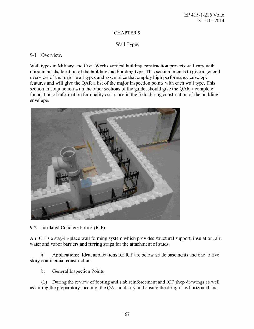
EP 415-1-216 Vol.6 31 JUL 2014
67
CHAPTER 9
Wall Types
9-1. Overview.
Wall types in Military and Civil Works vertical building construction projects will vary with mission needs, location of the building and building type. This section intends to give a general overview of the major wall types and assemblies that employ high performance envelope features and will give the QAR a list of the major inspection points with each wall type. This section in conjunction with the other sections of the guide, should give the QAR a complete foundation of information for quality assurance in the field during construction of the building envelope.
9-2. Insulated Concrete Forms (ICF).
An ICF is a stay-in-place wall forming system which provides structural support, insulation, air, water and vapor barriers and furring strips for the attachment of studs.
a. Applications: Ideal applications for ICF are below grade basements and one to five story commercial construction.
b. General Inspection Points
(1) During the review of footing and slab reinforcement and ICF shop drawings as well as during the preparatory meeting, the QA should try and ensure the design has horizontal and

EP 415-1-216 Vol.6 31 JUL 2014
68
vertical rebar at 8" increments (16 inches on center each way for example), as that is where rebar supports are located.
(2) On large projects if the product will be exposed for more than one month, the QA should check that ICF blocks are stored out of direct sunlight to prevent UV damage to blocks and ensure that work in place is covered to prevent any deterioration of the material.
(3) The QA should ensure that ICF's should only be put on footings +/- 1/4" from level
(4) Install first 2 or 3 courses of ICF block and then the QA should make sure contractor has checked for plumb and level (scribe or shim to get level as needed).
(5) The QA should verify, after ICF blocks are placed, that walls are plumb and tops of walls are straight
(6) The QA should check that strongback bracing is supported on a solid surface (like the footing) be anchored, and be every 6 or 7 feet down wall and on each side of every window or door opening.
(7) The QA should ensure adjustable turnbuckles are used with bracing to allow for adjustments.
(8) The QA should verify slump of concrete is approximately 6 inches and non angular aggregate and plasticizers are used (rather than excess water) and concrete is consolidated by vibrator. Recommended lift height for concrete placement is 3 to 4 feet and a typical wall height is 8 to 12 feet. Lifts on a continuous placement should be vibrated at the interface to avoid a cold joint.
(9) The QA should confirm proper consolidation of concrete around rebar, especially in congested spaces like lintels and door and window openings.
(10) The QA should check for straightness and plumbness of the wall again after consolidation of concrete.

EP 415-1-216 Vol.6 31 JUL 2014
69
9-3. Cold Formed Steel (CFS) Framing.
CFS framed assemblies typically consist of a cold-formed steel frame with C-shaped studs, tracks, joists, or rafters spaced at 16 or 24 inches apart.
a. Applications: Cold Formed Steel framing is an inexpensive method of framing walls. There are multiple similarities between wood stud and metal stud framing, making the ability to install them readily available. Many building codes require non-flammable construction for most buildings. Metal studs provide a simple, non-flammable framing solution.
b. General Inspection Points
(1) When insulation is specified to fit between members (e.g., in a wall cavity, attic or crawlspace floor), it is important for the QA to check that the Contractors used full width batts or a spray-applied product to fit tightly against the adjacent studs, completely filling the open end of the C-shape.
(2) If continuous exterior insulation is specified on walls, the QA needs to pay attention to address attachments to make sure the system is capable of securing the cladding (including corners), windows, doors, and any exterior accessories (lights, hose bibs, etc) through the foam insulation board into the CFS frame.
(3) The structural frame will need to be inspected by the QA for conformity with the contract drawings and specifications before covered by any interior finish.
(4) With more and more designs expected to specify continuous insulation, any required inspections of exterior structural bracing or sheathing will need to be conducted by the QA before the continuous insulation is installed (this applies to any framing system including CFS).
(5) The QA should make spot inspections of the condition of the CFS framing to ensure that the individual studs are not bent or buckled or other negative conditions that may occur during construction.
(6) The wall formed by the studs must be as close to plumb and straight as possible. The QA can accomplish this with a long straight edge by placing the straight edge horizontally against multiple vertical studs. Studs that are not up against the straight edge may need to be re-installed for the wall to be correct.
(7) Openings in CFS framed walls are similar in stud arrangement to wood stud walls. The QA needs to confirm that jack studs are located at the jamb as required. Double or triple vertical studs at head conditions of varying sizes is recommended based upon the span length and weight on the framed wall, and need to be verified against the contract documents by the QA.
(8) The QA needs to pay attention to areas where utilities pass through the stud cavity. Where wires pass through cut-outs a plastic or rubber grommet is required to keep the wiring insulation from being damaged or compromised. Copper piping needs to be isolated from direct contact with CFS to prevent metal deterioration due to dissimilar metals.
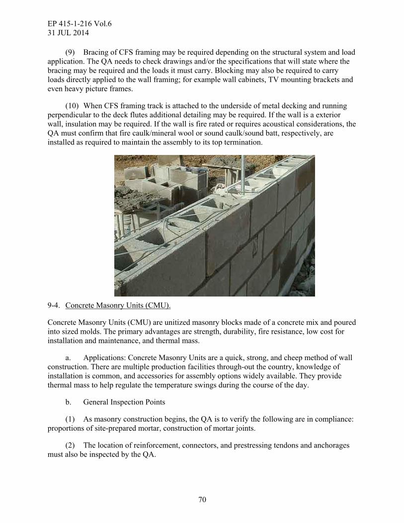
EP 415-1-216 Vol.6 31 JUL 2014
70
(9) Bracing of CFS framing may be required depending on the structural system and load application. The QA needs to check drawings and/or the specifications that will state where the bracing may be required and the loads it must carry. Blocking may also be required to carry loads directly applied to the wall framing; for example wall cabinets, TV mounting brackets and even heavy picture frames.
(10) When CFS framing track is attached to the underside of metal decking and running perpendicular to the deck flutes additional detailing may be required. If the wall is a exterior wall, insulation may be required. If the wall is fire rated or requires acoustical considerations, the QA must confirm that fire caulk/mineral wool or sound caulk/sound batt, respectively, are installed as required to maintain the assembly to its top termination.
9-4. Concrete Masonry Units (CMU).
Concrete Masonry Units (CMU) are unitized masonry blocks made of a concrete mix and poured into sized molds. The primary advantages are strength, durability, fire resistance, low cost for installation and maintenance, and thermal mass.
a. Applications: Concrete Masonry Units are a quick, strong, and cheep method of wall construction. There are multiple production facilities through-out the country, knowledge of installation is common, and accessories for assembly options widely available. They provide thermal mass to help regulate the temperature swings during the course of the day.
b. General Inspection Points
(1) As masonry construction begins, the QA is to verify the following are in compliance: proportions of site-prepared mortar, construction of mortar joints.
(2) The location of reinforcement, connectors, and prestressing tendons and anchorages must also be inspected by the QA.

EP 415-1-216 Vol.6 31 JUL 2014
71
(3) Grade and size of reinforcement, prestressing tendons and anchorages, placement of reinforcement, connectors and prestressing tendons, and anchorages must be inspected to ensure that they are in compliance with the required standards by the contract documents.
(4) The QA is to ensure that the masons do not lay masonry units having a temperature below 20ºF (-6.7ºC). Remove visible snow and ice on masonry units before the unit is laid in the masonry. Remove snow and ice from foundation. Heat existing foundation and masonry surfaces to receive new masonry above freezing. Heat mixing water or sand to produce mortar temperatures between 40 and 120ºF (4.4 and 48.9ºC). Grout materials to be 32ºF (0ºC) minimum. Do not heat water or aggregates above 140ºF (60ºC).
(5) At temperatures above 100ºF (37.8ºC) or above 90ºF (32.2ºC) with a wind speed greater than 8 mph (12.9 km/hr), the QA is to ensure that the Contractor maintains sand piles in a damp, loose condition. Maintain temperature of mortar and grout below 120ºF (48.9ºC). Flush mixer, mortar transport container, and mortar boards with cool water before they come into contact with mortar ingredients or mortar. Maintain mortar consistency by retempering with cool water. Use mortar within 2 hours of initial mixing.
(6) Where openings occur within concrete block walls, typically solid grouted reinforcement will be required on the sides of the opening. The QA is to verify that the head, jamb and sill condition is constructed as designed by the Structural Engineer. At the head condition, the lintel may vary by design. Grouted reinforced concrete masonry blocks, special bond beam blocks, cast concrete header, or even steel can be used. While each require different construction methods, all must utilize the required bearing size on the material below, and all must be tied into the remainder of the wall using steel reinforcing bars or studs.
(7) When rain is likely, the QA should ensure that all construction materials should be covered. Newly constructed masonry should be protected from rain by draping a weather-resistant covering over the assemblage. The cover should extend over all mortar that is susceptible to washout.
(8) Prior to grouting, the QA is to verify the following are in compliance: grout space, proportions of site-prepared grout and pre-stressing grout for bonded tendons, and construction of mortar joints.
(9) If an exterior masonry material (i.e. brick, split face block, cast stone, etc.) is to be the finish material, the QA is to verify that masonry ties are the proper type and laid out at the recommended spacing.
(10) The QA should ensure all embeds or structural attachments on the face of the block wall or on the top of the wall are properly grouted in place to ensure that they will not pull out when loaded.

EP 415-1-216 Vol.6 31 JUL 2014
72
9-5. Autoclaved Aerated Concrete (AAC).
Blocks or planks, whether with reinforcing steel or not inside, made up of a lightweight concrete approximately one fifth the weight of normal concrete. AAC has a large amount of air bubbles entrained into its structure, is easy to cut or rout to install electrical boxes, conduits, and other utilities. AAC can provide structural support, insulation, air barrier, vapor barrier, fire resistance and sound control in one width.
a. Applications: For complete AAC system, including walls and load bearing floor/roof planks - One to five story commercial construction with spans of rooms less than 15 feet, such as barracks and hotels. For walls only, any location needing load bearing block and/or panel masonry walls and non-load bearing partition and infill walls. Also, ACC is ideal for stair towers and elevator shafts and can provide good acoustic and fire protection in party walls.
b. General Inspection Points
(1) QA should verify that cores in the AAC block with reinforcing are present at all corners and openings.
(2) Spec Type M or S mortar for leveling bed mortar on slab or stemwall, and thinbed mortar for all head and bed joints above that. (contractor can mix little thinbed into Type M or S for extra stick if they like).
(3) QA should be aware that levelness of 1st course is important since thinbed mortar joints are 1/16 to 1/8” – not enough to make up for much leveling in each joint.
(4) Have AAC wall dowels specified to be drilled/epoxied into slab/stemwall to allow accurate location of them in field to match core locations in block. Contractor can lay out block
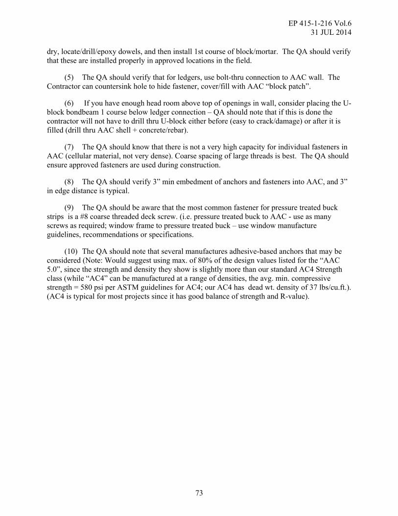
EP 415-1-216 Vol.6 31 JUL 2014
73
dry, locate/drill/epoxy dowels, and then install 1st course of block/mortar. The QA should verify that these are installed properly in approved locations in the field.
(5) The QA should verify that for ledgers, use bolt-thru connection to AAC wall. The Contractor can countersink hole to hide fastener, cover/fill with AAC “block patch”.
(6) If you have enough head room above top of openings in wall, consider placing the U-block bondbeam 1 course below ledger connection – QA should note that if this is done the contractor will not have to drill thru U-block either before (easy to crack/damage) or after it is filled (drill thru AAC shell + concrete/rebar).
(7) The QA should know that there is not a very high capacity for individual fasteners in AAC (cellular material, not very dense). Coarse spacing of large threads is best. The QA should ensure approved fasteners are used during construction.
(8) The QA should verify 3” min embedment of anchors and fasteners into AAC, and 3” in edge distance is typical.
(9) The QA should be aware that the most common fastener for pressure treated buck strips is a #8 coarse threaded deck screw. (i.e. pressure treated buck to AAC - use as many screws as required; window frame to pressure treated buck – use window manufacture guidelines, recommendations or specifications.
(10) The QA should note that several manufactures adhesive-based anchors that may be considered (Note: Would suggest using max. of 80% of the design values listed for the “AAC 5.0”, since the strength and density they show is slightly more than our standard AC4 Strength class (while “AC4” can be manufactured at a range of densities, the avg. min. compressive strength = 580 psi per ASTM guidelines for AC4; our AC4 has dead wt. density of 37 lbs/cu.ft.). (AC4 is typical for most projects since it has good balance of strength and R-value).

EP 415-1-216 Vol.6 31 JUL 2014
74
9-6. Tilt-up and Pre-Cast Concrete Panels.
Tilt-up construction is a method of delivering a reinforced concrete building envelope consisting of individual panels formed on or adjacent to the project site, often using the building slab. Pre-cast panels are similar to tilt-up panels with the exception being that the panels are produced at an off-site plant and trucked to the site for erection. These panels can satisfy the requirements for continuous insulation and air barrier as well as perimeter structure all in one monolithic element. Finish techniques include embedded items like thin brick, exposed aggregate, pigmented or stained concrete and many other finish options, patterns and graphics.
a. Applications: Tilt-up and Pre-cast panel applications include nearly every building type and are most common in structures 6 stories and less. Panels are as tall as 100-ft and as wide as 85-ft at times.
b. General Inspection Points
(1) The QA should verify accuracy of all panel shop drawings and rebar shop drawings to the approved contract drawings.
(2) QA should check that forms are installed and secured, and dimensions and tolerances verified per approved plans and/or shop drawings.

EP 415-1-216 Vol.6 31 JUL 2014
75
(3) QA should ensure that reinforcement and all embeds and inserts, as well as door frames and other cast-in items are installed and secured as required by approved plans and/or shop drawings.
(4) QA should verify that the approved concrete mix design, slump, and water cement ratio are being used prior to placement.
(5) QA should ensure that panels are erected to specific location and tolerance per the approved plans/shop drawings and that the panels are securely braced per TCA Wind Bracing Guidelines.
(6) QA should check that panel base grout installed (ready mix or non-shrink) as soon as possible.
(7) QA should confirm that permanent connections to building diaphragms are inspected and approved prior to any brace removal.
(8) QA should verify that all non-grout panel joints are completed with required treatment (e.g. backer rod(s), caulk, fire stop if required, etc.) per approved plans/shop drawings.
(9) QA should ensure that panel surfaces are completed to project documents and/or TCA Guideline Specifications for appropriate grade level finish.
(10) QA should check that all building envelope components adjacent to tilt-up panels are secured and tested for appropriate continuity and structural integrity, if applicable.

EP 415-1-216 Vol.6 31 JUL 2014
76
THIS PAGE INTENTIONALLY LEFT BLANK

EP 415-1-216 Vol.6 31 JUL 2014
77
CHAPTER 10
Air Leakage Test Protocol
10-1. Building Air Tightness Requirement.
The basic air tightness requirements and processes for USACE projects is the following:
a. Design and construct the building envelopes of office buildings, office portions of mixed office and open space (e.g., company operations facilities), dining, barracks and instructional/training facilities) with a continuous air barrier to control air leakage into (or out of) the conditioned space. Clearly identify the boundary limits of the building air barriers and of the portion or portions of the building to be tested for building air tightness on the construction documents. Clearly identify all air barrier components of each envelope assembly on construction documents and detail the joints, interconnections and penetrations of the air barrier components.
b. Join and seal the air barrier materials of each assembly to the air barrier materials of adjacent assemblies, allowing for the relative movement of these assemblies and components. Clearly identify air barrier system continuity on the plan and section construction drawings.
c. Provide details to seal all penetrations of the air barrier assembly, including but not limited to electrical, plumbing and HVAC components; windows and doors; compatibility of materials with one another.
d. Support the air barrier so that it shall withstand the maximum positive and negative air pressures that will be placed on the building without displacement, or damage, and transfer the load to the structure. The air barrier assembly must be durable to last the anticipated service life of the envelope.
e. Provide a motorized damper in the closed position and connect it to the fire alarm system to open on call and fail in the open position for any fixed open louvers such as at elevator shafts. Dampers and controls shall close all ventilation or make-up air intakes and exhausts, atrium smoke exhausts and intakes, etc where leakage can occur during inactive periods. Garages under buildings shall be compartmentalized by providing air-tight vestibules at building access points. Provide air-tight vestibules at building entrances with high traffic.
f. Compartmentalize spaces under negative pressure such as boiler rooms and provide make-up air for combustion.
10-2. Performance Requirement and Substantiation.
a. Demonstrate performance of the continuous air barrier assembly for the building envelope by the following steps:
b. Submit the qualifications and experience of the testing entity for approval.
c. Verify that the building envelope has been sufficiently completed for testing.

EP 415-1-216 Vol.6 31 JUL 2014
78
d. Notify the USACE at least three working days prior to tests being conducted to provide them the opportunity to witness the testing procedures.
e. Test the completed building and demonstrate that the air leakage rate of the building envelope does not exceed the requirements in accordance with this document.
f. Determine air leakage pathways using ASTM E1186-03(2009) ‘Standard Practices for Air Leakage Site Detection in Building Envelopes and Air Barrier Systems’. Retest after corrective work is completed as necessary to achieve the whole building air leakage rate requirements.
g. Provide the USACE with written test results of all testing and inspection procedures.
10-3. Specifier and Witness Guidance. Application and Scope.
The witness and specifier should be familiar with all sections of this document. Use the Application and Scope (section 4.3) to gain a general understanding of the air leakage testing, how it should be specified and how to monitor whether the air leakage test has been properly performed. See the included Glossary and Acronyms (section 5).
10-4. Defining the Test Boundary.
The design professional is responsible for defining the test boundary and for calculating the associated surface area to be used in the normalized air leakage calculation. The location and surface area of the test boundary shall be clearly defined in the project documents. When possible, the whole building will be tested as a single space (single zone). When this is not practical, one of the following alternate methods can be used:
a. All individual spaces within the building will be tested as individual zones and subject to the building envelope air leakage requirements in Table 11-1. In this case the results are normalized to the surface area of all six sides of the enclosed test space.
b. A guarded test can be conducted. In a guarded test, the air pressure difference between the test zone and surrounding conditioned zones is maintained at zero during each test point. In this way, the air leakage through the exterior test zone enclosure is measured. In this case, the test result is normalized to the surface area of the test zone enclosure. A test plan shall be proposed by contractor and accepted by the USACE prior to a guarded test being performed.
10-5. Whole Building Testing.
Whenever a single zone building test is performed, there will be a single test boundary for the entire building. This boundary may not always be comprised exclusively of exterior walls. For example, heating, ventilating, and air-conditioning (HVAC) rooms with large louvers, electrical rooms, laundry facilities with mechanical ventilation to the outside with dampers and loading docks which all open to outdoors may be designed to be outside of the air barrier assembly. As such, the test boundary will not encompass these spaces and it will align with the interior walls of these spaces. In such building envelope designs, these examples of interior walls are part of the air barrier of the building, and must be air sealed to the same level of detail as other parts of

EP 415-1-216 Vol.6 31 JUL 2014
79
the air barrier that face the outdoor elements. When performing a single zone test in a building that is not completely open inside, the interior zones in the building need not be interconnected by large openings if they can be tested to demonstrate compliance with the test pressure uniformity requirements in section 4.
10-6. Individual Room or Dwelling Testing.
When it is not possible to test a whole building as a single zone, the multiple zone tests must include all the surfaces which make up the entire building envelope. For example, in a building where doorways of the apartments/offices/rooms do not lead to common spaces such as hallways, it would be impractical to simultaneously test all spaces together as a single zone, and each apartment/office/room must be tested individually. In this case of individual room testing, walls between adjacent rooms are to be treated as part of the envelope in spite of the fact that some leakage would be to another conditioned space and could therefore be ignored. Common walls will be treated as part of the test boundary for the zone and each zone must pass the normalized leakage test criteria, with the following exception.
a. When testing an individual room or dwelling, all adjacent spaces must be open to the outdoors.
b. When conducting individual room testing in multi-unit apartments, at least 20% of the apartments must be tested, including all corner rooms, and including at least one of each style of apartment.
10-7. Test Spaces Contained within Larger Zones.
Buildings may include spaces that require testing which are partially or wholly located within unconditioned zones that do not require testing. For example, office and break room facilities located within an unconditioned equipment maintenance facility require air barrier testing, but the maintenance facility envelope does not. In such cases the air barrier test boundary surrounds the envelope of each conditioned space that requires testing. The spaces requiring testing may be adjoined or detached, have some exterior walls or may be entirely within the unconditioned enclosure. These spaces are also often small relative to the entire building, and smaller capacity fans meeting equipment requirements may be used. Testing should be conducted with the unconditioned zone open to the outdoors. Each of the detached and contiguous spaces may be tested separately; adjoined, unconnected spaces will require separate test fans or temporary, intentional openings between the adjacent zones in order to maintain uniform building pressures during testing. Multiple spaces may be tested simultaneously provided that the pressures meet the pressure uniformity requirement in Section 4.6.
10-8. Larger Buildings.
Buildings requiring flow in excess of 200,000 cfm at 75 Pa have been successfully tested using standard techniques. Some larger buildings may require special test techniques not covered in this document primarily because of limitations in test fans. One option is to separate the building into multiple temporary test zones using boundary pressure neutralization techniques. A second option is to erect temporary walls to create multiple test zones. A third option may be to use the building HVAC system to establish test pressures. These three special techniques will require a

EP 415-1-216 Vol.6 31 JUL 2014
80
higher level of experience and engineering to establish useful results. It is up to the specifier to establish conformance criteria and test procedures for these unique buildings with the help of the testing agency. The Canadian General Standards Board (CGSB) standard CAN/CGSB-149.15, ‘Determination of the Overall Envelope Air tightness of Buildings by Fan Pressurization Method Using the Building’s Air Handling Systems’ could be referenced by the specifier and used by the testing agency for option three. In summary, the importance of air tightness testing must not be lost on buildings with envelopes requiring test air flows in excess of 200,000 CFM75, and tests of these buildings should be performed, even if some limitations of the standard test procedure are necessary.

EP 415-1-216 Vol.6 31 JUL 2014
81
CHAPTER 11
Air Leakage Specification
11-1. General.
A common air leakage test specification can be summarized as follows:
a. The air leakage test must be performed in accordance with this document.
b. The test consists of measuring the flow rates required to establish a minimum of ten (+10) positive and ten (-10) negative approximately equally spaced induced envelope pressures. Induced envelope pressure test points shall be averaged over at least 10seconds and shall be no lower than 40 Pa for a two-sided (positive and negative) test and 50 Pa for a single sided test. The highest point must be at least 75 Pa, and there must be at least 25 Pa difference between the lowest and highest point. Pressures in the extremities of the envelope must not differ from one another by more than 10% of the average induced envelope pressure. Twelve pre and twelve post-baseline pressure points must be taken across the envelope with respect to the outdoors where each point is an average taken over at least 10 seconds. The maximum absolute baseline pressure point value must not exceed 30% of the minimum induced envelope pressure test point used in the analysis. There are no further restrictions on wind speed or temperature during the test.
c. Building envelopes shall be tested under pressurization and de-pressurization conditions unless an air flow in excess of 200,000 CFM75 is required to perform the test and the only air flow testing method can pressurize or depressurize but not both.
The mean value (of pressurization and depressurization if both are performed) of the air leakage flow calculated from measured data at 0.3 in wc (75 Pa) must not exceed the building envelope air leakage requirements in Table 11-1 and the confidence intervals requirements of Table 12-9.
Building Type Maximum Air Leakage Requirement
All buildings 0.25 (CFM75/sq ft)
Table 11-1 – Building Envelope Air leakage Requirement
d. Additional information for the specifier. The Testing Agency Guide (section 4) provides detailed information as to how the test must be performed. A completed test must consist of all items from the Air Leakage Test Form included in appendix A with required attachments including the page titled Air Leakage Test Results (from appendix A), upon which the testing agency must make a pass or fail declaration. A computer-generated test report containing all of the information in the air leakage test form in appendix A is permitted as long as the calculations used in the program are in accordance with equations in this document. Note the following:

EP 415-1-216 Vol.6 31 JUL 2014
82
(1) The following requirements pertain to masking HVAC openings other than flues:
(a) The test is conducted with ventilation fans and exhaust fans turned off and the outdoor air inlets and exhaust outlets sealed (by dampers and/or masking),
(b) Motorized dampers must be closed and may be tested masked or unmasked,
(c) Undampered HVAC openings must be masked during testing, and
(d) Gravity dampers shall be prevented from moving or can be masked.
(2) In some cases, recirculating air handlers may also need to be turned off. The building contractor must provide a responsible HVAC technician with the authority to place the HVAC system in the correct mode for the pressure test. The testing agency must have unhindered access to mechanical rooms, air handlers, exhaust fans, and outdoor air and exhaust dampers.
(3) Portable fans manufactured for the purpose of pressure testing buildings often require significant electrical power (e.g., 20 amps) and can trip circuit breakers. The building contractor must have someone on site with access to and the authority to reset circuit breakers or must have access and authority granted to them.
(4) Air flow and envelope pressure differences are drastically affected when exterior doors or windows are opened. At the time of the test, the building contractor must ensure that all windows in the test envelope are kept closed and latched and there shall be no entry and exit through doors in the test envelope during the test. Pressures and flows that are affected by these door openings and closings must not be included in the calculations.
(5) Test fans are generally placed in doors of the test envelope. Other openings in the test envelope may be used. The testing agency must have access to these locations, be able to open them, and be allowed to remove closure hardware, cladded alarm wiring and other objects that interfere with test equipment set-up.
(6) The contractor shall ensure that no sub-contractors are working in the area of the test fans during their operation. ASTM E779-10, 7.0 shall be reviewed and followed to ensure any occupational hazards associated with operating test fans are eliminated to create a safe work environment.
(7) The air leakage test to determine final compliance with the air tightness requirement shall be conducted when all components of the air barrier assembly have been installed and inspected, and have passed any intermediate testing procedures as detailed in the construction drawings and specifications. The test may be conducted before finishes that are not part of the air barrier assembly have been installed. For example, if suspended ceiling tiles, interior gypsum boards, or cladding systems are not part of the air barrier assembly, the test may be conducted before they are installed.
(8) The testing agency is required to perform a diagnostic evaluation in accordance with ASTM E1186-03 (2009), whether the building achieves the air tightness requirement or not. The

EP 415-1-216 Vol.6 31 JUL 2014
83
diagnostic evaluation will assist the building contractor and other responsible parties in identifying and eliminating air leakage.
(9) The testing results will be expressed in terms of the equivalent leakage area @ 75 Pa (EqLA75). EqLA75 is the equivalent area, in square feet of a flat plate that leaks the same amount as the building envelope @ 75 Pa. This information helps those responsible for further sealing the envelope to know the approximate size of total leakage area they should be seeking. Air leaks can consist of many small cracks, or a few very large openings or a combination of both. It is not unusual for large buildings to have an EqLA75 of up to 100 sq ft. It is also common for air sealing efforts to be focused on the small cracks while large holes that are a major contributor to failing the test, go unnoticed. Even if the building achieves the required air tightness requirement, a thorough diagnostic evaluation should be conducted to help the construction team identify additional areas of leakage that could be sealed on the current building or similar future buildings. At a minimum, a visual inspection, a feel test, a fog test, and a thermography test shall be performed to identify leakage areas.
(10) Any building that does not meet the leakage rates specified in Table 11-1 shall be repaired and retested until it conforms to the leakage rates specified.

EP 415-1-216 Vol.6 31 JUL 2014
84
THIS PAGE INTENTIONALLY LEFT BLANK

EP 415-1-216 Vol.6 31 JUL 2014
85
CHAPTER 12
Testing Agency Guide
12-1. U.S. Army Corps of Engineers (USACE) Standard for Air Leakage.
The USACE requires all new buildings and major renovation projects to pass an air leakage test where the results must not exceed the building envelope air leakage requirements in Table 11-1 of differential pressure at standard conditions specified in ASTM E779-10.USACE Procedure. The following sections along with the Air Leakage Test Form in appendix A define this test protocol.
12-2. Application and Scope.
See the Application and Scope for specifiers and witnesses. Pay special attention to the discussion of whole building testing versus individual room or dwelling testing.
12-3. Test Equipment Air flow Capacity.
The minimum induced pressure for a valid test is 75 Pa. In planning for a test, the test agency must determine how much test air flow capacity they will need on site and supply that amount for the test. For whole building testing in single-zone buildings, and in the absence of any other information, the test agency should plan to bring a quantity of pressurization equipment to site that would be sufficient to provide0.30 CFM/sq ft of flow against a pressure of 75 Pa. Since the true leakage rate goal is 0.25 CFM/sq ft of flow at 75 Pa, the potential additional flow allows a comfortable margin to account for baseline pressures, reduced on-site voltages or other effects which could prevent the theoretical induced pressure from being attained. For example, if the building had 100,000 sq ft of envelope area, then it would theoretically require 100,000 x 0.25 = 25,000 CFM75 to induce a pressure of 75 Pa. If the test agency brings equipment capable of 30,000 CFM75, they should very easily be able to reach 75 Pa if the building meets the specification. If 25,000 CFM is brought into the building and 75 Pa cannot be achieved, the building fails the air leakage test. There are other very important considerations, some of which are listed below.
a. Bottlenecks or Zones without Interior
Access. If a building is not well connected internally (relative to its leakage rate) fans may need to be separated from one another, amongst two or more locations in order to achieve pressure uniformity. This may increase the number of fans required for the test as opposed to increasing the total fan capacity.
b. Test Logistics.
In some cases, multiple buildings are scheduled for testing on the same day or days. Depending on the test equipment used, it may be more efficient to set up multiple buildings for testing in advance of the witnesses arriving and then be prepared to run the tests back to back without the delays associated with moving the equipment. In this case more test fans and other associated equipment may be required.

EP 415-1-216 Vol.6 31 JUL 2014
86
c. Power Considerations.
For certain test equipment, due to power quality considerations such as long extension cords, the test fans might not deliver their full rated capacity when used on site. Consult the fan manufacturer for information of this nature.
d. Use of Building
HVAC System for Testing. HVAC systems may be used to conduct the building airtightness tests if all of the following conditions are met:
(1) In buildings that require 200,000 CFM or less to induce an envelope pressure of 75 Pa, the test must be conducted in both pressurization and depressurization mode. In buildings that require 200,000 CFM or more to induce an envelope pressure of 75 Pa, the building HVAC systems may be used to conduct the building air tightness test in either pressurization or depressurization mode.
(2) A proposed test plan must be submitted and pre-approved by the USACE.
(3) The building HVAC system must be specifically designed and installed to conduct the building air tightness test or be modified with flow measuring stations or other devices to allow accurate air flow measurements for testing.
(4) Air flow measurement devices must be documented to measure air flows within 5% of actual flows. E.g. in situ calibration of flow stations over the range of expected flow measurements.
(5) Pressure gauges must be digital with a resolution of 0.1 Pa and accurate to within ±1% of reading or ±0.25 Pa, whichever is greater, and must have a means of adjustable time averaging to compensate for wind.
For single zone tests on very large buildings, (typically requiring a test air flow in excess of 200,000 CFM75) the techniques above may be the practical option. There may not be an American standard that adequately addresses this issue. Canada uses the CAN/CGSB-149.15 standard for very large buildings. In the hands of experienced personnel, reasonable results may be achieved, but note that accuracies have been reported to be no better than ± 20% when 75 Pa was achieved.
e. Floor-by-Floor Test Method. In buildings in excess of four stories, if the testing agency’s equipment is not capable of achieving a uniform pressure within the building due to the geometry of the interior partitions and limited shaft and stairwell interconnections, it may be possible to isolate and test individual floors. However, the floor-by-floor method requires exceptional preparation and knowledge of air flow characteristics within chases, shafts, and wall cavities in addition to the difficulty of maintaining an identical or balanced pressure between the floors above and below. Refer to the ASHRAE study, ‘Protocol for Field Testing of Tall Buildings to Determine Envelope Air Leakage Rate 935-RP (Bahnfleth 1998)’ for additional information on the floor-by-floor method of testing. It is recommended that the whole building achieve a uniform pressure to avoid the uncertainty inherent in the floor-by-floor method, but

EP 415-1-216 Vol.6 31 JUL 2014
87
this protocol does not prohibit the application of the floor-by-floor method as an option for buildings greater than four stories in height.
f. Pressure Gauge and Test Fan Accuracy Requirements- Pressure gauges must be digital with a resolution of 0.1 Pa and accurate to within ±1% of reading or ±0.25 Pa, whichever is greater, and must have a means of adjustable time averaging to compensate for wind. Pressure gauges shall have their calibration checked and accuracy verified minimum every two (2) years (or sooner, based on the gauge manufacturer’s recommendations) against a National Institute of Standards and Technology (NIST) traceable standard over at least 16 pressures from at least +250 to -250 Pa or to the greatest pressure used during a test. Test fan measurement equipment shall have their calibration verified at least every four (4) years in compliance with ASTM E1258-88(2008). Calibration certificates must show the deviations from the calibration equations that must not exceed ± 5% of the flow reading for a range of air flows and backpressures (the pressure across the fan). For each test fan flow range configuration used in a test, the calibrations shall include the minimum and maximum air flows allowed by the manufacturer for that range plus at least one intermediate flow. For each flow rate, calibrations shall include data at backpressures within +/- 10% of 25, 50, and 75 Pa. Digital pressure gauges and test fans may be calibrated separately and used interchangeably as long as they meet the requirements of this section.
12-4. Building Envelope Pressure Measurement.
A minimum of one building envelope pressure measurement channel is required. It has been shown that the use of multiple building envelope pressure measurement locations, averaged together can be helpful in reducing wind-induced pressure deviations. Electronic or pneumatic means of averaging may be used. If electronic averaging is used it is recommended to have available a means of observing the individual points for comparison. This can be helpful in assessing wind impacts as well as identifying problems.
12-5. Interior Pressure Uniformity.
Pressure differences within the test zone shall be monitored to confirm that it is uniform within 10% of the average induced envelope pressure. Test fans must be installed to satisfy this requirement. This may require test fans to be widely separated from one another. Care shall be taken to install interior pressure difference measurement equipment to ensure that it is unaffected by velocity pressure created by the test equipment air flow. As an example of the uniformity criterion, for an induced envelope pressure of 75 Pa, the maximum difference between any two locations within the test zone must be 7.5 Pa or less. The number of indoor pressure difference measurements required to prove uniformity will depend on the presence of air flow bottle necks that could create significant pressure drops (e.g., doorways and stairwells).
12-6. Pre-Test Inspection and Equipment Check.
Ensure that the test equipment is in operable condition prior to arriving at the test site. A pre-test visual inspection must be performed to determine whether there are any factors that would prevent the test from being completed. The operation of the equipment is the simplest part of the test, whereas preparing the building is the most complex, takes the most time, and is the most likely factor to prevent the testing agency from completing the test on time.

EP 415-1-216 Vol.6 31 JUL 2014
88
12-7. Before Starting the Test
a. Record Set-up Conditions. Accurately record the exact building and equipment set up conditions. Pictures should be taken of representative setup conditions and should be attached to the final report. The intent of this protocol is to ensure buildings are set up and prepared in a specified manner so that the tests are reproducible. The testing agency is responsible to ensure that the building is properly prepared and that the preparations are maintained throughout the test documentation showing the type and location of test fans, pressure gauges and the associated pneumatic tubing routes should also be provided in the final report.
b. Preparation of the Building. The contractor typically performs the actual building preparations described below.
(1) Seal o r otherwise effectively isolate all “intentional” holes in the test boundary. This includes air intake or exhaust louvers, make-up air intakes, pressure relief dampers or louvers, dryer and exhaust vent dampers and any other intentional hole that is not included in the air barrier design or construction. The following requirements pertain to masking HVAC openings other than flues:
(a) The test is conducted with ventilation fans and exhaust fans turned off and the outdoor air inlets and exhaust outlets sealed (by dampers and/or masking),
(b) Motorized dampers must be closed and may be tested masked or unmasked,
(c) Undampered HVAC openings must be masked during testing, and
(d) Gravity dampers shall be prevented from moving or can be masked.
(2) Fenestrations are included in the air barrier test boundary. Exterior windows and doors shall be in the closed and locked position only; no additional films or additional means of isolation at fenestrations is allowed.
(3) Ensure that all plumbing traps are filled with water.
(4) The HVAC system must be shut down or disabled for the duration of the test. If the HVAC system activates during the test, additional air movement is introduced within the test zone, resulting in inaccurate test data.
(5) All interior doors connecting to rooms within the test zone must be held open during the test to create a single uniform zone. If the door services only an interior room such as a storage closet, it is allowed to remain closed only if a dropped ceiling plenum is present above and none of the room’s surface is part of the air barrier assembly. If doorways cannot be opened and the volume on the other side of the door is considered to be within the tested volume, then the pressure across that doorway must be measured with the test fan(s) running to ensure that the space on the other side of the door meets the pressure uniformity requirement.
(6) Buildings with a dropped ceiling plenum must have four (4) sq ft of tiles removed for every 500 sq ft of ceiling area. Additional tiles may be removed at the discretion of the testing

EP 415-1-216 Vol.6 31 JUL 2014
89
agency so a uniform pressure distribution in the plenum space is achieved. As an alternative the dropped ceiling plenum pressure can be tested to see if the building meets the pressure uniformity requirements of section 4.6 with the tiles in place.
(7) All vented, non-sealed combustion equipment must be disabled or be in the “pilot” position. Confer with responsible party to ensure safe conditions during pressure test, ie. mechanical contractor, facility manager, building operator or controls contractor. If the test zone is within a larger building envelope such as a Tactical Equipment Maintenance Facility or Company Operations Facility, the areas outside of the test zone must be at ambient (outdoor) pressure conditions. This can be achieved by opening windows, exterior personnel doors or overhead coiling (rollup) doors that open to outdoors.
12-8. Performing the Test.
a. Complete the test sequence as outlined in the USACE Air Leakage Test Form (template attached).
b. There are additional details to be observed which are specific to the test equipment used and beyond the scope of this document. The test agency is required to abide by the test equipment manufacturer’s instructions to ensure proper application of test equipment.
c. Because this test is performed by pressurizing and depressurizing the building envelope, baseline pressure effects are minimized, yielding more accurate results. This is the preferred test method since it is not only more tolerant of test conditions, but also gives a more accurate representation of the building envelope leakage under ambient conditions, where pressures can be either positive or negative in direction. Baseline pressures may be up to 30% of the lowest induced envelope pressure, allowing this method to be used in a wider range of weather conditions.
d. The testing agency must achieve at least 75 Pa at or below the passing leakage air flow to prove the building is sufficiently airtight to pass the building envelope air leakage requirements in Table 11-1. The agency is encouraged to achieve the highest building pressure possible, but should not exceed 85 Pa.
e. Note that some buildings may have air barrier assemblies that have not been properly designed and/or installed, and this may limit the maximum safe building envelope pressure to less than 75 Pa. In such cases the building does not meet the building envelope air leakage requirement of Table 11-1. The testing agency shall perform a multi-point test in general accordance with this protocol so an approximate air leakage value can be provided to the building contractor. This will allow an estimate of the magnitude of the repairs necessary to meet the air leakage requirement.

EP 415-1-216 Vol.6 31 JUL 2014
90
12-9. Reporting of Results.
The data collected during the multi-point tests will be corrected for standard conditions and used to determine the air leakage coefficient, C, and the pressure exponent, n, in accordance with this document:
nPCCFM *
a. The values C and n in the above equation are calculated using a linear regression of the natural log of the flow (in CFM) versus the natural log of the baseline-adjusted building envelope pressures (in Pa). The testing agency must take data at a minimum of ten (10) building envelope pressures for each test, but is not limited to the maximum number of building envelope pressures measured during the test. It is recommended to record data at additional building envelope pressures so in the analysis the “outliers” will not materially affect the calculation procedure. Outliers are pressure and flow data points that do not fit the linear regression well, and they can be caused by wind gusts, changes in wind direction, door openings, etc. Data gathered while exterior doors are open shall not be included in the analysis.
b. Flow rates in CFM75/sq ft @75 Pa (CFM75/sq ft) must be calculated for the linear regressions for both the pressurization and the depressurization data sets. The average of those two flow rates will be divided by the building envelope area in square feet given in the project drawings to determine the final CFM75/sq ft. This average value will be used as the basis for determination if the building meets or does not meet the requirement for maximum building envelope air leakage requirements in Table 11-1. The value is to be rounded to the nearest hundredth. For example, a value of 0.255 would be rounded to 0.26.
c. In addition to reporting the normalized air leakage in units of CFM75/sq ft, the testing agency is also required to report the squared correlation coefficient (r2) and the 95% confidence intervals (95% CI) of both the pressurization and depressurization test to demonstrate the accuracy of the data collected and the quality of the relationship between flow and pressure that was established during the test. The 95% CI and r2 must be calculated in strict accordance with the methodology contained in this document, and the data used in these calculations must correspond to the data used for the linear regressions.
d. In general, a narrower 95% CI to the mean value and higher r2 value indicates a clear relationship for the building’s air leakage characteristics was established. Use Table 12-9 to make a pass/fail determination.

EP 415-1-216 Vol.6 31 JUL 2014
91
Result (CFM75/sq ft) ± value for 95% CI Determination of Test Results
Less than or equal to 0.25
≤ 0.02 (CFM75/sq ft) Pass
> 0.02 (CFM75/sq ft) Pass if upper limit ≤ 0.25
Fail if upper limit > 0.25
Greater than 0.25 ≤ 0.02 (CFM75/sq ft) Fail
> 0.02 (CFM75/sq ft) Fail
Table 12-9 – Pass/Fail Determination Chart
e. Regardless of the magnitude of the final result, the r2 value must be above 0.98.
f. The pressure exponent, n, will also provide some insight as to the validity of the test and relative tightness of the building envelope. Exponent values less than 0.50 or greater than 1.0 in theory indicate a bad test, but in practice, tests outside the range of 0.45 to 0.80 would generally indicate an inaccurate test or calculation methodology. This range is dictated by basic fluid dynamics and the characteristics of developing air flow through leaks, which is too lengthy to discuss within this protocol. Except for very rare circumstances, n values should not take on values less than 0.45 and not greater than 0.80. If the n value is outside of these boundaries, the test must be repeated.
g. The testing agency is required to produce the data used in the analysis and results in tabular and graphical form, including the curve fitted coefficients and correlation coefficient.
(1) Several common conditions that will cause test results to be much lower than they should be, are:
(a) Interior pressure monitoring stations are placed too close to direct air flow that is typically produced by the test fans.
(b) Usually tests are conducted with the fan inlet fully open, allowing maximum air flow. For testing tighter building envelopes that require smaller test flows, the fan manufacturer provides a flow restriction device such as a plug or plastic ring that can be installed on the fan. When limiting the fan air flow, some systems require that the digital gauge’s configuration be adjusted. If the gauge is incorrectly set on a lower range than the fan, then the measured flow will be much lower than the actual flow.
(c) Interior doors have been left closed.
(2) Several common conditions which will cause results to be much higher than they should be, are:

EP 415-1-216 Vol.6 31 JUL 2014
92
(a) Intentional openings have not been properly sealed or have opened during the test (i.e., pressure relief dampers, plumbing traps).
(b) Windows or exterior doors are left open.
(c) HVAC equipment is not properly disabled.
(d) If the gauge is set on a higher range than the fan, then the measured flows will be much higher than the actual flow.
12-10. Locating Leakage Sites with Pressurization and Depressurization.
a. The testing agency is required to perform a diagnostic evaluation (including infrared thermography) in general accordance with ASTM E1186-03(2009). The testing agency can use additional methods to discover leaks. It is important to determine the source of the leakage. It is also beneficial for the design-build team to understand the locations and details that are susceptible to leakage, even if the building as a whole passes the test.
b. Neutral buoyancy smoke, theatrical smoke and infrared thermography are effective means to find leakage sites. When testing equipment pressurizes the building envelope, air leaks can be seen from outdoors (provided exterior walls have not been heated by radiation from the sun) using infrared thermography or large scale smoke generation. When testing equipment depressurizes the building envelope, air leaks can be observed from the inside using infrared thermography or smoke generation. When the building interior temperature is close to the outdoor temperature, then cooling or heating of the building by the HVAC system may be required to perform an effective infrared thermography scan because it requires a temperature differential of at least 10°F.
c. In general, when locating leaks, the air flow equipment should be adjusted to establish a minimum pressurization of +25 Pa pressure differential to use smoke or infrared while viewing the building from outdoors. A depressurization differential of -25 Pa should be used when using infrared or smoke from the interior. Additional guidance for the diagnostic evaluation should be in accordance with ASTM E1186-03(2009).
12-11. Thermography Requirements.
Accreditation of Thermographers. The testing agency must employ thermographers with experience in building enclosures and building physics to achieve accurate diagnoses and to make effective recommendations to the design-build contractor in the event of failure and repair. An Infrared thermographer is required by this protocol to perform the infrared diagnostic evaluation. To be qualified to conduct work under this protocol, the infrared thermographer must have successfully completed, at a minimum, a course of study that fully complies with the Level I educational requirements of the American Society for Nondestructive Testing (ASNT) as described in SNT-TC-1A-2006 and ANSI/ASNT CP-105, Training Outlines for Qualification of Nondestructive Personnel (2006). In addition, the infrared thermographer must also have a minimum of two (2) years experience in building science applications with infrared thermography or have achieved minimum Level II based on ANSI/ASNT requirements listed above.

EP 415-1-216 Vol.6 31 JUL 2014
93
12-12. Infrared Imaging System Calibration.
The infrared imaging system shall be calibrated by the manufacturer. Field verification of the calibration shall be made by the operator on a periodic basis to ensure the system is within calibration. Written records of verification shall be provided upon request.
12-13. Infrared Imaging System Specifications.
The native detector array shall be at least 240 by 180 pixels. The thermal sensitivity or Noise Equivalent Temperature Difference (NETD) shall be 100mK or less (or >0.1ºC).

EP 415-1-216 Vol.6 31 JUL 2014
94
Glossary and Acronyms
ACH Air Changes per Hour
ACH50 Air Changes per Hour at 50 pascals of pressure; a unit of measure commonly used in envelope testing for Passive House compliance.
air barrier assembly A combination of air barrier materials and building components that are designated and designed within the building envelope to act as a continuous barrier to the movement of air.
air barrier material A building product designed and constructed to provide the primary resistance to air flow through the building envelope. An air barrier material(s) shall have an air permeance not to exceed 0.004 CFM/sq ft at 0.3 in wc [0.02 L/(s·m2) @ 75 Pa] when tested in accordance with American Society for Testing and Materials (ASTM) E2178-03.
air leakage The movement/flow of air through the building envelope, which is driven by either or both positive (infiltration) or negative (exfiltration) pressure differences or test pressures across the building envelope. See also airtightness .
air leakage rate The volume of air movement/unit time across the building envelope.
air tightness or airtightness Property of a building envelope which will inhibit air leakage, airtightness is determined by measuring the air flow rate required to maintain a specific induced test pressure. In this protocol airtightness is measured and reported in units of CFM/sq ft of air leakage at a uniform test pressure of 75 Pa.
AOR Architect of record
ASHRAE American Society of Heating, Refrigerating, and Air-Conditioning Engineers
ASTM American Society for Testing and Materials

EP 415-1-216 Vol.6 31 JUL 2014
95
baseline pressure The building envelope pressure with test fans off and sealed, recorded while the building is in the test condition. The terms bias, static pressure readings and zero-flow pressure difference are used interchangably with the term baseline pressure in other documents/standards used in the industry.
building envelope The architectural elements of a building that form a barrier between its conditioned interior space and the exterior environment; the building shell or enclosure. It includes the top, bottom, and all sides (roof, walls, floor/foundation) both above and below grade.
CD Compact Disk
CERL Construction Engineering Research Laboratory
CFM/sq ft @ 75 Pa or CFM75/sq ft
CFM75/sq ft is the flow rate, in CFM, required to pressurize or depressurize the building by 75 Pa.
CFM75 cubic feet per minute at an induced building envelope pressure of 75 pascals
CGSB Canadian General Standards Board
CI Confidence Interval
conditioned space Any mechanically heated and/or cooled space.
conduction The transmission of heat through, along or from one material to another material in contact with it.
convection The transfer of heat by circulation of air due to temperature differences; hotter air rises as cooler air falls
DOD Department of Defense
DOE Department of Energy

EP 415-1-216 Vol.6 31 JUL 2014
96
effective leakage area A common term used to describe air flow at a pressure by equating it to an equivalent size hole in an elliptical nozzle that would pass the same air flow at the same test pressure. It is usually taken at 4 Pa and incorporates a 1.0 discharge coefficient. It is typically about half the size of an equivalent leakage area that describes the same air flow rate. See ASTM E779-10, eq. (5).
emissivity Emissivity is a measure of the flow of heat radiated from the surface of a material.
envelope pressure Differential pressure between the interior of the building being tested and the outdoors, measured with the outdoors as the reference. See sections 4.5 and 4.6.
envelope, building The architectural elements of a building that encloses conditioned space; the building shell. It includes the top, bottom, and all sides (roof, walls, floor/foundation)
EPS expanded polystyrene; a lightweight, rigid, plastic foam insulation material produced from solid beads of polystyrene
EqLA Equivalent leakage area; usually referenced to 10 Pa, commonly called ELA but EqLA is used to avoid confusion.
EqLA75 Equivalent leakage area @ 75 Pa assuming a discharge coefficient of 0.611. This is a special case of EqLA.
equivalent leakage area A common term used to describe air flow at a pressure by equating it to an equivalent size hole in a flat plate that would pass the same air flow at the same test pressure. It is usually taken at 10 Pa and incorporates a 0.611 discharge coefficient. For the purposes of this document, it is taken at a reference pressure of 75 Pa and is referred to as EqLA75. It is typically about twice the size of an effective leakage area that describes the same air flow rate. See ASTM E779-10, eq. (5).
ERDC Engineer Research and Development Center
ERDC-CERL Engineer Research and Development Center, Construction Engineering Research Laboratory

EP 415-1-216 Vol.6 31 JUL 2014
97
exfiltration Movement/flow of air through the building envelope from inside to outside due to pressure differences.
fan pressurization method Method defined in ASTM E779-10. Even though this term contains the word “pressurization” this does not indicate that exclusively positive pressures are to be used.
guarded test The test is conducted by zeroing the pressure difference between the test zone and surrounding conditioned zone and consequently only the air leakage through the exterior portions of the test zone enclosure is measured.
HVAC Heating, ventilating, and air-conditioning
induced envelope pressure The change in envelope pressure caused by operation of the test fans. Calculated as the difference between the envelope pressure with the test fan(s) on and the average baseline pressure. Induced envelope pressures are positive during pressurization tests and negative during depressurization tests.
induced envelope pressure test point
Each point consists of the average induced envelope pressure and the average test fan flow reading required to induce that pressure.
infiltration Movement/flow of air through the building envelope from outside to inside due to pressure differences.
IR infrared
ISO International Organization for Standardization
ITC Infrared Training Center
NETD Noise Equivalent Temperature Difference, a measure of the thermal accuracy of IR cameras (in miliKelvins or °C)
NIST National Institute of Standards and Technology
normalized air leakage Total leakage air flow divided by test boundary surface area, with temperature and elevation corrections.
EP 415-1-216 Vol.6 31 JUL 2014
98
outdoors Outside the building in the area around the building.
Passive House Passive House or PassivHaus (German) refers to a voluntary standard for energy use in buildings which enphaises high performing building envelopes as a primary strategy for compliance.
permeability The rate that water or vapor will pass through a membrane. The results are expressed in “perms” with the lower the number meaning the less moisture vapor will pass through the membrane. (1 perm = the passage of 1 grain of vapor through 1ft2 of material in 1 hour under a vapor pressure of 1 inch of mercury.)
permeance Water vapor permeance is a measurement of vapor transmission as a performance evaluation. It is typically reported in perm-inches (1 perm-inch = the passage of 1 grain of vapor through 1ft2 of 1 inch thick material in 1 hour under a pressure difference of 1 inch of mercury.)
single zone For this protocol, a space in which the pressure difference between any two places differs by no more than 10% of the inside to outside pressure difference. Not to be confused with the ASTM E779-10 definition in which the pressure differences may be no more than 5% by the same measure.
sq ft Abbreviation for “square feet”
STP Standard temperature and pressure conditions of 14.696 psi (101.325 KPa) and 68F (20°C).
test boundary Boundary of the portion of the building which is actually tested. The area of this boundary is used in the results calculation.
test fan For this document, this term is used to represent a calibrated variable speed fan that is typically temporarily mounted in an opening in the envelope for the purpose of providing a test pressure and for measuring the flow rate required to establish that test pressure. Other commonly used terms are "blower door" and "door fan".

EP 415-1-216 Vol.6 31 JUL 2014
99
Thermal Bridge A Thermal Bridge is a penetration of the insulating layer of a building envelope by a highly conductive or noninsulating material between the interior conditioned space and exterior a building resulting in energy loss.
time averaging Refers to the digital gauge display or other means of averaging pressures over a time interval. Time averaging can be block averages that will update for the length of the average or non-overlapping rolling (moving) averages that will update continuously by displaying the average over the past time period.
US United States
US DOD U.S. Department of Defense
US DOE U.S. Department of Energy
USACE U.S. Army Corps of Engineers
zero flow pressure ASTM E779-10 terminology for baseline pressure.

EP 415-1-216 Vol.6 31 JUL 2014
100
THIS PAGE INTENTIONALLY LEFT BLANK

EP 415-1-216 Vol.6 31 JUL 2014
101
Attachment
Sample Test Report Template

Building Envelope Testing Template USACE Air Leakage Test Protocol for Building Envelopes
This form conforms to USACE procedures and requirements
Building name: ________________________________________________________________________
Building address: ______________________________________________________________________
Project Number: ____________________________ Installation: _____________________________
Prime contractor: ______________________________________________________________________
Contact: _____________________________________________________________________________
Testing agency: _______________________________________________________________________
Address: _____________________________________________________________________________
Testing agency contact: _________________________________________________________________
Phone: _______________________________ Email: ______________________________________
Lead on‐site personnel: ____________________________ Phone: ___________________________
Test date: ____________________________________________________________________________
Additional information: _________________________________________________________________
_____________________________________________________________________________________
_____________________________________________________________________________________
Witness Name: Organization: Telephone/Email:
___________________________ ___________________________ ___________________________
___________________________ ___________________________ ___________________________
___________________________ ___________________________ ___________________________
___________________________ ___________________________ ___________________________
___________________________ ___________________________ ___________________________

INSERT PHOTOGRAPHS OF SUBJECT BUILDING AND TESTING APERATUS:
The testing agency provides digital photographs of subject building, setup, test procedures, and diagnostic evaluation.

1. Test Boundary Dimensions
1.1. ___ Record the total test boundary surface area in square feet including walls, floor and ceiling from design plans as supplied by the architect of record (AOR).
1.2. ___ Verify the building envelope square footage used by the AOR is reasonable. 1.3. ___ Attach a description of the building characteristics, including intended use,
wall, roof, and floor construction, fenestrations, HVAC system, air barrier system, and any additional information that may be relevant to the air leakage test.
1.4. ___ Record elevation of building above sea level in feet.
1.5. ___ Record the height of the building above grade.
________sq ft
__________ ft
__________ ft
2. Set Up Checklist
2.1. ___ Confirm HVAC shutdown/disabling. 2.2. ___ Confirm all dampers in the envelope perimeter are closed and/or isolated. 2.3. ___ Confirm exhaust fans & dryers are off and isolated at the air barrier. 2.4. ___ Confirm combustion appliances are on pilot or are disabled. 2.5. ___ Confirm all air inlets at the envelope perimeter are sealed or isolated. 2.6. ___ Confirm all interior doors are propped open. 2.7. ___ Confirm all air outlets at the envelope perimeter are prepared per section 4.8.2. 2.8. ___ Note rain or snow conditions that may be affecting leakage of walls.
_____________________________________________________________________________________
_____________________________________________________________________________________
2.9. ___ Confirm exterior doors and windows are closed and latched. 2.10. ___ Confirm all areas outside of air barrier envelope being tested are at ambient conditions. 2.11. ___ Confirm all plumbing traps are filled with water. 2.12. ___ Confirm dropped ceiling tiles are removed at specified rate. 2.13. ___ Confirm uniform interior pressure distribution by inducing an envelope pressure of at least
30 Pa. Measure interior pressure differences to ensure no two locations differ in pressure by more than 10% of the induced envelope pressure. Document uniform interior pressure distribution by recording the locations and values of interior pressure differences in tabular or graphic form. Data may be collected by hand or acquisition equipment.
Primary pressure _____________Pa
Interior Pressure differences and where they were measured
________________________ Pa _____________________________Pa
________________________ Pa _____________________________Pa

2.14. ___ Document the approximate locations of the envelope pressure measurements in tabular or graphic format including the interior and exterior locations for each envelope pressure channel.
_____________________________________________________________________________________
_____________________________________________________________________________________
2.15. Exterior pressures are:
_______ manifolded together, _______ electronically averaged or, ________manually averaged 2.16. Record additional set up notes.
_____________________________________________________________________________________
_____________________________________________________________________________________
_____________________________________________________________________________________
3. Testing Equipment Used
3.1. ___ List gauge(s):
model serial # accuracy calibration date
____________________ ____________________ ____________________ ____________________
____________________ ____________________ ____________________ ____________________
____________________ ____________________ ____________________ ____________________
____________________ ____________________ ____________________ ____________________
____________________ ____________________ ____________________ ____________________
____________________ ____________________ ____________________ ____________________
3.2. ___ Confirm the gauge has an accuracy of ± 1 % or 0.25 Pa, whichever is greater and has had its
calibration checked against a National Institute of Standards and Technology (formerly National Bureau of Standards, or NIST) traceable standard within two (2) years.
3.3. ___ List test‐fan(s):
model # serial # accuracy calibration date
____________________ ____________________ ____________________ ____________________
____________________ ____________________ ____________________ ____________________
____________________ ____________________ ____________________ ____________________
____________________ ____________________ ____________________ ____________________
____________________ ____________________ ____________________ ____________________

3.4. ___ Confirm the test fan has an air flow measurement accuracy of ± 5 percent of the measured flow and has had its calibration checked against an NIST traceable standard within four
(4) years. 3.5. ___ List infrared camera(s):
model serial # accuracy calibration date
____________________ ____________________ ____________________ ____________________
____________________ ____________________ ____________________ ____________________
____________________ ____________________ ____________________ ____________________
3.6. ___ Field verification of infrared camera calibration conducted within the preceeding two months of test date.
3.7. ___ Attach calibration certificates for all equipment listed above to the air leakage test form. If additional fans or gauges are used during the test, attach calibration certificates.
4. Induce Envelope Pressures with Test Fans
4.1. ___ Both pressurization and depressurization tests performed. 4.1.1. ___ The building target tightness rate is more the 200,000
cfm @75 Pa and may therefore be tested in one direction which will be:
________pressurizationOR
______depressurization
4.2. ___ Operator will be located inside or outside the tested building. 4.3. ___ Record indoor and outdoor temperatures before the test.
4.4. ___ Record initial baseline envelope pressure in Pa in accordance with
section 3.2. Show positive and negative signs. Data may be collected by hand or acquisition equipment and be reported in tabular or graphic form.
4.5. ___ Baseline pressure from 4.4.
4.6. ___ Record the time duration of the baseline envelope pressure (minimum 120 seconds).
4.7. ___ Collect a series of at least 10 approximately equally spaced induced
envelope pressure test points where each point consists of the average induced envelope pressure and the average test fan flow reading required to induce that pressure. Induced envelope pressure test points shall be averaged over at least 20 seconds and shall be no lower than 25 Pa. The highest point must be at least 75 Pa, no greater than 85 Pa, and there must be at least 25 Pa difference between the lowest and highest.
______ insideOR
_____outside
_____°F inside
___ °F outside
_________Pa. _________sec

___________ ___________ ___________ ___________
___________ ___________ ___________ ___________
___________ ___________ ___________ ___________
4.8. ___ Record pressure differentials to demonstrate compliance with the internal pressure uniformity requirement of no two locations differing from one another by more than 10% of the induced envelope pressure. Document compliance at each induced envelope pressure test point.
NOTE: See step 2.13. ‐ Document uniform interior pressure distribution by
recording the locations and values of interior pressure differences in tabular or graphic form. Data may be collected by hand or acquisition equipment.
4.9. Record final baseline envelope pressure in Pa in accordance with section
3.2. Show positive and negative signs. Data may be collected by hand or acquisition equipment and be reported in tabular or graphic form.
4.10. ___ Subtract the average baseline envelope pressure (obtained from 4.5
and 4.9) from all pressures in 4.7 to determine the induced envelope pressures for use in section 5.
4.11. ___ Record the indoor and outdoor temperature after the test.
4.12. ___ Calculate the total corrected flow for all test‐fans using the range and
flow data from 4.10. Use temperatures and altitude to correct to STP using equations from ASTM E779‐10.
4.13. Repeat in the opposite test direction unless 4.1.1 applies.
_________Pa.
_________Pa.Average baseline
____°F indoor
___°F outdoor
5. Calculate and Report Results Curve fit all corrected pressures and flows from the tables and calculate the following values in strict accordance with ASTM E779‐10. Attach all data in a tabular and graphical form.
Pressurization
5.1. ___ The temperature and altitude air leakage coefficient CP for
pressurization. 5.2. ___ The exponent np for pressurization. NOTE: if np is less than 0.45 or
CP
________np

greater than 0.8, test data are invalid and test must be repeated. 5.3. CFM referenced to standard temperature and pressure (STP) at +75 Pa.
5.4. ___ CFM75/sq ft of envelope at +75 Pa.
5.5. ___ The correlation coefficient, r2, of the curve fitted data. NOTE: If r2 is less than 0.98, test data are invalid and test must be repeated. 5.6. If both pressurization and depressurization tests have been completed, go
to 5.8. ___If only a pressurization test is completed, calculate the 95% confidence interval at +75 Pa for test in pressurization using methods from ASTM E779‐10.
Depressurization 5.7. ___ The temperature and altitude air leakage coefficient Cd for
depressurization. 5.8. ___ The exponent nd for depressurization. NOTE: If np is less than 0.45 or greater than 0.8, test data is invalid and test must
be repeated. 5.9. ___ CFM referenced to standard temperature and pressure (STP) at
‐75 Pa 5.10. ___ CFM75/sq ft of envelope at ‐75 Pa
5.11. ___ The correlation coefficient, r2 of the curve fitted data. NOTE: If r2 is less than 0.98, test data are invalid and test must be repeated.
5.12. If both pressurization and depressurization tests have been completed,
go to 5.15. ___ If only a depressurization test is completed, calculate the 95% confidence interval at ‐75 Pa for test in depressurization using methods found in this document.
_________CFM75
____________ CFM75/sq ft
____________
____________
____________
____________
____________
____________
5.13. ___ Calculate the average CFM75/sq ft from 5.4 and 5.10.
5.14. ___ Calculate the 95% confidence interval at 75 Pa for combined pressurization and depressurization using methods found in this document.
____________CFM75/sq ft

5.15. ___ Consult Table 4.10.1 to determine pass/fail status based on the average of pressurization and depressurization.
5.16. ___ For the purpose of visualizing the magnitude of the air leakage of the
enclosure calculate the equivalent leakage area in square feet at 75 Pa.
____________Upper limitCFM75/sq ft
Pass/Fail
EqLA75 =
_________sq ft
6. Infrared Leakage Evaluation
Perform a diagnostic evaluation in accordance with ASTM E1186‐03(2009) ’Standard Practices for Air Leakage Site Detection in Building Envelopes and Air Barrier Systems’. Attach results of diagnostic evaluation to this test form.
7. Confirm these building components have been returned to pre‐test conditions 7.1. ___ HVAC 7.2. ___ All dampers in the envelope perimeter 7.3. ___ Exhaust fans & dryers 7.4. ___ Combustion appliances 7.5. ___ All air inlets at the envelope perimeter 7.6. ___ All interior doors 7.7. ___ All air outlets at the envelope perimeter 7.8. ___ Exterior doors and windows 7.9. ___ Dropped ceiling tiles
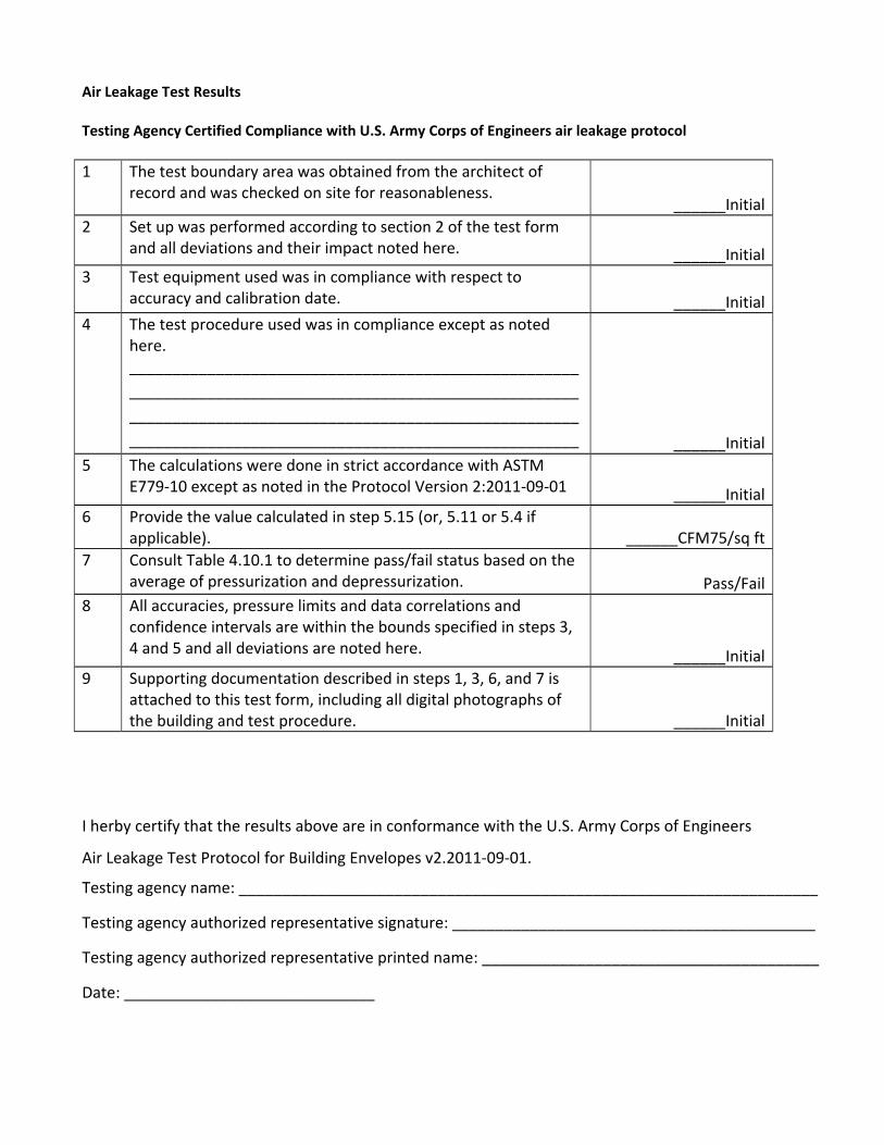
Air Leakage Test Results Testing Agency Certified Compliance with U.S. Army Corps of Engineers air leakage protocol
1 The test boundary area was obtained from the architect of record and was checked on site for reasonableness.
______Initial
2 Set up was performed according to section 2 of the test form and all deviations and their impact noted here. ______Initial
3 Test equipment used was in compliance with respect to accuracy and calibration date. ______Initial
4 The test procedure used was in compliance except as noted here. ____________________________________________________
____________________________________________________
____________________________________________________
____________________________________________________ ______Initial
5 The calculations were done in strict accordance with ASTM E779‐10 except as noted in the Protocol Version 2:2011‐09‐01 ______Initial
6 Provide the value calculated in step 5.15 (or, 5.11 or 5.4 if applicable). ______CFM75/sq ft
7 Consult Table 4.10.1 to determine pass/fail status based on the average of pressurization and depressurization. Pass/Fail
8 All accuracies, pressure limits and data correlations and confidence intervals are within the bounds specified in steps 3, 4 and 5 and all deviations are noted here. ______Initial
9 Supporting documentation described in steps 1, 3, 6, and 7 is attached to this test form, including all digital photographs of the building and test procedure. ______Initial
I herby certify that the results above are in conformance with the U.S. Army Corps of Engineers
Air Leakage Test Protocol for Building Envelopes v2.2011‐09‐01.
Testing agency name: ___________________________________________________________________
Testing agency authorized representative signature: __________________________________________
Testing agency authorized representative printed name: _______________________________________
Date: _____________________________

Air Tightness Standards Reference
For comparison purposes this appendix lists the airtightness targets for several programs:
The U.S. Army Corps of Engineers (USACE)
Government Services Agency (GSA)
British best practices and normal existing buildings
Passivehaus US
The USACE and GSA targets are written in the same units – CFM 75/sq ft enclosure. The British targets are also normalized to the enclosure area but are in m3/hr/m2 enclosure and referenced at 50 Pa. The Passivehaus US target is expressed in air changes per hour at 50 Pa. The targets are not directly comparable because:
Targets at different reference induced pressure differences depend on the value of the flow
exponent measured for each building. An assumption of flow exponent must be made to
compare them.
Targets normalized to building volume rather than surface area varies differently than those
normalized to surface area. They vary in proportion to the surface to volume ratio. A specific
volume must be assumed to compare them.
The target airtightness values are compared in Table A1 for a two story, 100 foot by 240 foot by 25 foot building with a flow exponent equal to 0.60. For larger or smaller buildings or for different flow exponents the results will vary.

British best practice
m3/hr50/m2
enclosure
British normal
m3/hr50/m2
enclosure ACH50 CFM75/sq ft enclosure British ATTMA
Office ‐Natural Ventilation 3 7 1.1/2.5* 0.21/0.49*
Office ‐ mixed ventilation 2.5 5 0.89/1.8* 0.18/0.35*
Office ‐AC/low energy 2 5 0.71/1.8* 0.14/0.35* Factories/ warehouses 2 6 0.71/2.1* 0.14/0.42* superstores 1 5 0.36/1.8* 0.07/0.35* schools 3 9 1.1/3.2* 0.21/0.68* hospitals 5 9 1.8/3.2* 0.35/0.68* museums/ archives 1 1.5 0.36/0.53* 0.07/0.11* cold stores 0.2 0.35 0.07/0.13* 0.014/0.025* dwellings ‐NV 3 9 1.1/3.2* 0.21/0.68* dwellings ‐MV 3 5 1.1/1.8* 0.21/0.35*
ASHRAE Std 189, GSA 5.7* ‐‐ 2* 0.40
Army Corps of Engineers 3.6* ‐‐ 1.3* 0.25 Passivhaus 1.7* ‐‐ 0.6 0.12*
NOTE: Numbers in italics are the units used in the standards
* assuming a two story, 48,000 square foot floor area, 100 foot by 240 foot x 25 foot building with flow exponent = 0.60.