Embed Size (px)
Citation preview
Energy Harvesting and Mission Effectiveness
for Small Unmanned Aircraft
Mark J. Cutler∗ Timothy W. McLain†
Randal W. Beard‡
Brigham Young University, Provo, Utah, 84602 USA
Brian Capozzi§
Mosaic ATM, Leesburg, Virginia, 20175 USA
This paper explores the feasibility of improving unmanned air vehicle (UAV) missioneffectiveness by extracting energy from the atmosphere. Specifically, we consider an aerialsurveillance mission in the vicinity of a geographic ridge. Cross winds flowing over theridge produce regions of lift on the windward side that can be exploited to increase missionduration. Mission effectiveness is quantified using the seeability metric. Simulation resultsare presented for several observation target placements. Results indicate that seeabilityand imaging persistence can be improved by exploiting ridge lift. Simulations demonstratedthat targets at ranges less than four times the ridge height were able to be observed overan indefinite period by a UAV with a glide ratio of 11:1.
I. Introduction
For small unmanned air vehicles (UAVs) atmospheric effects, such as vertical wind components, thermals,gusts, and wind gradients, represent significant sources of energy that an aircraft can potentially tap toincrease endurance and range. These effects are typically transient and geographically dependent, thus theability to exploit them as an energy resource requires the ability to detect them and characterize their sizeand location. For intelligence, surveillance, and reconnaissance (ISR) missions, the objective is often toprovide persistent observation of a target of interest. The goal of this paper is to explore the effectiveness ofenergy harvesting and its potential to enhance ISR mission effectiveness. The primary challenge associatedwith harvesting atmospheric energy and performing ISR simultaneously is that they are competing objectiveslikely requiring the UAV to perform in characteristically different ways to be successful. Furthermore, thetime and location of atmospheric energy sources may not coincide with the time and location of the targetof interest.
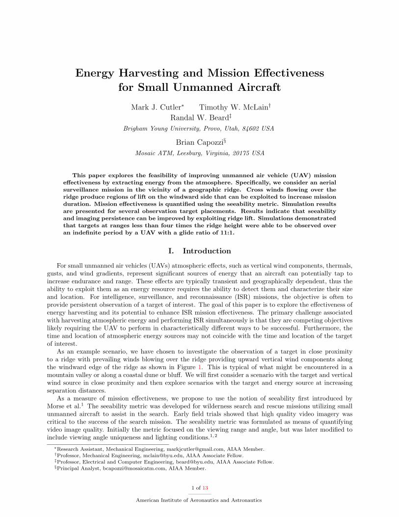
As an example scenario, we have chosen to investigate the observation of a target in close proximityto a ridge with prevailing winds blowing over the ridge providing upward vertical wind components alongthe windward edge of the ridge as shown in Figure 1. This is typical of what might be encountered in amountain valley or along a coastal dune or bluff. We will first consider a scenario with the target and verticalwind source in close proximity and then explore scenarios with the target and energy source at increasingseparation distances.
As a measure of mission effectiveness, we propose to use the notion of seeability first introduced byMorse et al.1 The seeability metric was developed for wilderness search and rescue missions utilizing smallunmanned aircraft to assist in the search. Early field trials showed that high quality video imagery wascritical to the success of the search mission. The seeability metric was formulated as means of quantifyingvideo image quality. Initially the metric focused on the viewing range and angle, but was later modified toinclude viewing angle uniqueness and lighting conditions.1,2
∗Research Assistant, Mechanical Engineering, [email protected], AIAA Member.†Professor, Mechanical Engineering, [email protected], AIAA Associate Fellow.‡Professor, Electrical and Computer Engineering, [email protected], AIAA Associate Fellow.§Principal Analyst, [email protected], AIAA Member.
1 of 13
American Institute of Aeronautics and Astronautics
Figure 1. Energy harvesting ISR scenario.
Atmospheric energy harvesting for increased range and endurance is not a new concept. Birds have beenobserved flying hundreds of kilometers without flapping their wings by taking advantage of thermal andridge lift. Manned sailplane and hang glider pilots also routinely use energy available in the air for long-distance, long-duration cross-country flight. Autonomous atmospheric energy harvesting for small UAVs hasbecome an active area of research in recent years. Wharington3 first suggested autonomous soaring, or theuse of thermals, in 1998 to increase small UAV endurance. Allen4,5 and Edwards6 recently demonstratedflight results of autonomous thermal soaring algorithms. Langelaan7 explored optimal flight trajectories forminimum flight time and maximum energy gain while traversing a ridge. Exploiting ridge lift for stationarytarget observation has not yet been explored. The goal of this work is to investigate the potential for energyharvesting to enhance the effectiveness of an ISR mission.
II. Technical Approach
This section describes the technical approach taken in investigating ISR mission effectiveness while har-vesting energy from vertical wind components near a ridge line. Section A describes the seeability metricused as a measure of mission effectiveness, while Section B describes the wind model used for flow over aridge and the algorithm utilized to harvest energy from the vertical components of the wind near the ridge.
A. Seeability Metric
The concept of seeability was first developed in response to needs observed during wilderness search andrescue (WiSAR) field training exercises. In these experiments, small UAVs were used to perform aerialsearches for lost individuals. A key observation from early experiments was that search victims were oftendifficult to detect, even when the UAV sensor footprint passed over them repeatedly. The need to quantifythe quality of video imagery was clearly evident. The seeability metric was developed to fill this need.
Morse, et al.1 defined the seeability metric for a point i in camera frame j as
Sij =
ni·vij
1+dij/αif point i is visible in frame j,
0 otherwise,(1)
where ni is the terrain surface normal, vij is the pointing direction of the camera, dij is the distance fromthe camera to point i, and α is a scaling factor. This represents the instantaneous seeability, which is ameasure of how well a particular point on the ground can be seen at a particular instant of time. The notionof cumulative seeability was also defined, which captures the cumulative benefit of multiple unique views of
2 of 13
American Institute of Aeronautics and Astronautics
the point of interest. The seeability concept has been extended by Niedfeldt et al.2 to include target size,target/background contrast, and lighting/shading.
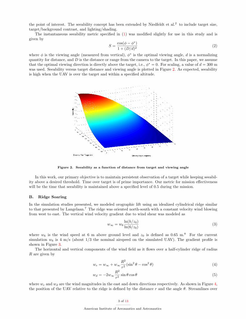
The instantaneous seeability metric specified in (1) was modified slightly for use in this study and isgiven by
S =cos(φ− φ∗)1 + (D/d)2
(2)
where φ is the viewing angle (measured from vertical), φ∗ is the optimal viewing angle, d is a normalizingquantity for distance, and D is the distance or range from the camera to the target. In this paper, we assumethat the optimal viewing direction is directly above the target, i.e., φ∗ = 0. For scaling, a value of d = 300 mwas used. Seeability versus target distance and viewing angle is plotted in Figure 2. As expected, seeabilityis high when the UAV is over the target and within a specified altitude.
Figure 2. Seeability as a function of distance from target and viewing angle
In this work, our primary objective is to maintain persistent observation of a target while keeping seeabil-ity above a desired threshold. Time over target is of prime importance. Our metric for mission effectivenesswill be the time that seeability is maintained above a specified level of 0.5 during the mission.
B. Ridge Soaring
In the simulation studies presented, we modeled orographic lift using an idealized cylindrical ridge similarto that presented by Langelaan.7 The ridge was oriented north-south with a constant velocity wind blowingfrom west to east. The vertical wind velocity gradient due to wind shear was modeled as
w∞ = w6ln(h/z0)ln(6/z0)
(3)
where w6 is the wind speed at 6 m above ground level and z0 is defined as 0.65 m.8 For the currentsimulation w6 is 4 m/s (about 1/3 the nominal airspeed on the simulated UAV). The gradient profile isshown in Figure 3.
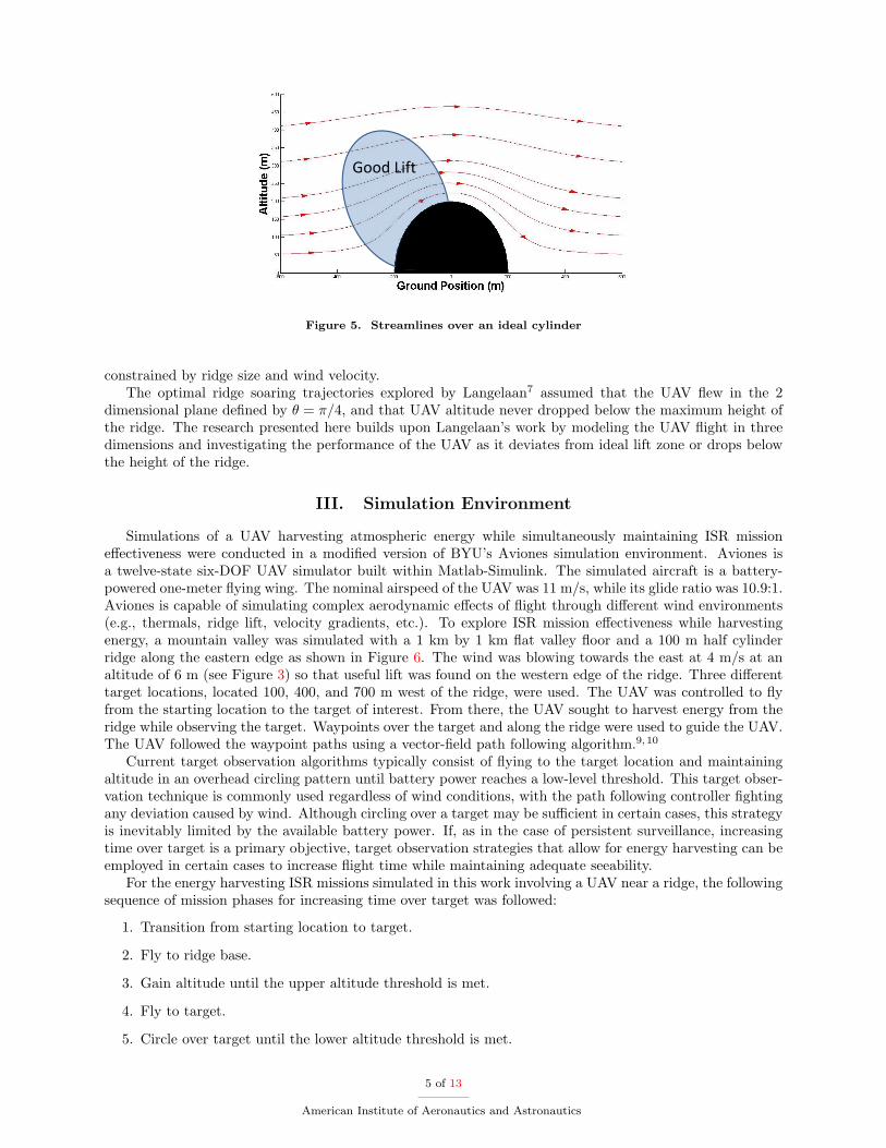
The horizontal and vertical components of the wind field as it flows over a half-cylinder ridge of radiusR are given by
we = w∞ + w∞R2
r2(sin2 θ − cos2 θ) (4)
wd = −2w∞R2
r2sin θ cos θ (5)
where we and wd are the wind magnitudes in the east and down directions respectively. As shown in Figure 4,the position of the UAV relative to the ridge is defined by the distance r and the angle θ. Streamlines over
3 of 13
American Institute of Aeronautics and Astronautics
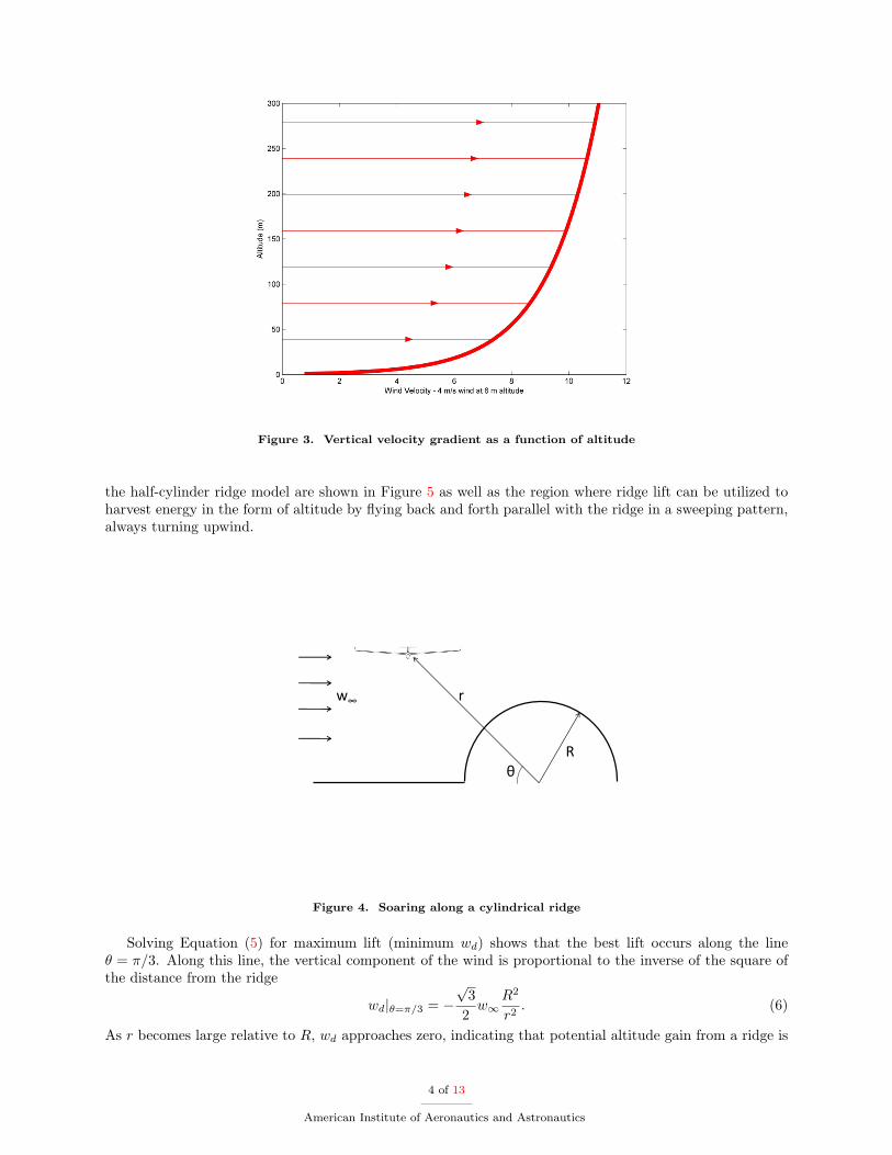
Figure 3. Vertical velocity gradient as a function of altitude
the half-cylinder ridge model are shown in Figure 5 as well as the region where ridge lift can be utilized toharvest energy in the form of altitude by flying back and forth parallel with the ridge in a sweeping pattern,always turning upwind.
r
Rθ
w∞
Figure 4. Soaring along a cylindrical ridge
Solving Equation (5) for maximum lift (minimum wd) shows that the best lift occurs along the lineθ = π/3. Along this line, the vertical component of the wind is proportional to the inverse of the square ofthe distance from the ridge
wd|θ=π/3 = −√
32w∞
R2
r2. (6)
As r becomes large relative to R, wd approaches zero, indicating that potential altitude gain from a ridge is
4 of 13
American Institute of Aeronautics and Astronautics
Good Lift
Figure 5. Streamlines over an ideal cylinder
constrained by ridge size and wind velocity.The optimal ridge soaring trajectories explored by Langelaan7 assumed that the UAV flew in the 2
dimensional plane defined by θ = π/4, and that UAV altitude never dropped below the maximum height ofthe ridge. The research presented here builds upon Langelaan’s work by modeling the UAV flight in threedimensions and investigating the performance of the UAV as it deviates from ideal lift zone or drops belowthe height of the ridge.
III. Simulation Environment
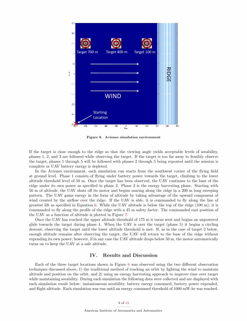
Simulations of a UAV harvesting atmospheric energy while simultaneously maintaining ISR missioneffectiveness were conducted in a modified version of BYU’s Aviones simulation environment. Aviones isa twelve-state six-DOF UAV simulator built within Matlab-Simulink. The simulated aircraft is a battery-powered one-meter flying wing. The nominal airspeed of the UAV was 11 m/s, while its glide ratio was 10.9:1.Aviones is capable of simulating complex aerodynamic effects of flight through different wind environments(e.g., thermals, ridge lift, velocity gradients, etc.). To explore ISR mission effectiveness while harvestingenergy, a mountain valley was simulated with a 1 km by 1 km flat valley floor and a 100 m half cylinderridge along the eastern edge as shown in Figure 6. The wind was blowing towards the east at 4 m/s at analtitude of 6 m (see Figure 3) so that useful lift was found on the western edge of the ridge. Three differenttarget locations, located 100, 400, and 700 m west of the ridge, were used. The UAV was controlled to flyfrom the starting location to the target of interest. From there, the UAV sought to harvest energy from theridge while observing the target. Waypoints over the target and along the ridge were used to guide the UAV.The UAV followed the waypoint paths using a vector-field path following algorithm.9,10
Current target observation algorithms typically consist of flying to the target location and maintainingaltitude in an overhead circling pattern until battery power reaches a low-level threshold. This target obser-vation technique is commonly used regardless of wind conditions, with the path following controller fightingany deviation caused by wind. Although circling over a target may be sufficient in certain cases, this strategyis inevitably limited by the available battery power. If, as in the case of persistent surveillance, increasingtime over target is a primary objective, target observation strategies that allow for energy harvesting can beemployed in certain cases to increase flight time while maintaining adequate seeability.
For the energy harvesting ISR missions simulated in this work involving a UAV near a ridge, the followingsequence of mission phases for increasing time over target was followed:
1. Transition from starting location to target.
2. Fly to ridge base.
3. Gain altitude until the upper altitude threshold is met.
4. Fly to target.
5. Circle over target until the lower altitude threshold is met.
5 of 13
American Institute of Aeronautics and Astronautics
RID
GE
WIND
Target 700 m Target 400 m Target 100 m
Starting Location
Figure 6. Aviones simulation environment
If the target is close enough to the ridge so that the viewing angle yields acceptable levels of seeability,phases 1, 2, and 3 are followed while observing the target. If the target is too far away to feasibly observethe target, phases 1 through 5 will be followed with phases 2 through 5 being repeated until the mission iscomplete or UAV battery energy is depleted.
In the Aviones environment, each simulation run starts from the southwest corner of the flying fieldat ground level. Phase 1 consists of flying under battery power towards the target, climbing to the loweraltitude threshold level of 50 m. Once the target has been observed, the UAV continues to the base of theridge under its own power as specified in phase 2. Phase 3 is the energy harvesting phase. Starting with50 m of altitude, the UAV shuts off its motor and begins soaring along the ridge in a 200 m long sweepingpattern. The UAV gains energy in the form of altitude by taking advantage of the upward component ofwind created by the airflow over the ridge. If the UAV is able, it is commanded to fly along the line ofgreatest lift as specified in Equation 6. While the UAV altitude is below the top of the ridge (100 m), it iscommanded to fly along the profile of the ridge with a 45 m safety factor. The commanded east position ofthe UAV as a function of altitude is plotted in Figure 7.
Once the UAV has reached the upper altitude threshold of 175 m it turns west and begins an unpoweredglide towards the target during phase 4. When the UAV is over the target (phase 5) it begins a circlingdescent, observing the target until the lower altitude threshold is met. If, as in the case of target 2 below,enough altitude remains after observing the target, the UAV will return to the base of the ridge withoutexpending its own power; however, if in any case the UAV altitude drops below 50 m, the motor automaticallyturns on to keep the UAV at a safe altitude.
IV. Results and Discussion
Each of the three target locations shown in Figure 6 was observed using the two different observationtechniques discussed above, 1) the traditional method of tracking an orbit by fighting the wind to maintainaltitude and position on the orbit, and 2) using an energy harvesting approach to improve time over targetwhile maintaining seeability. During each simulation the following data were collected and are displayed witheach simulation result below: instantaneous seeability, battery energy consumed, battery power expended,and flight altitude. Each simulation was run until an energy consumed threshold of 1000 mW-hr was reached.
6 of 13
American Institute of Aeronautics and Astronautics
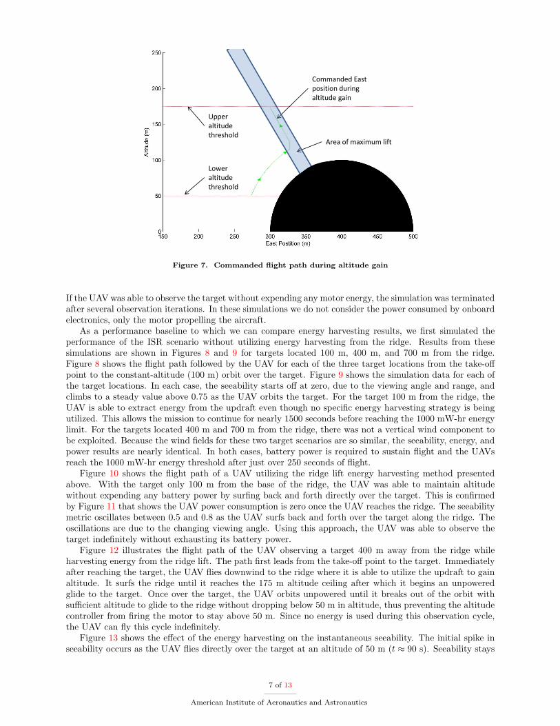
Upper altitude threshold
Lower altitude threshold
Commanded East position during altitude gain
Area of maximum lift
Figure 7. Commanded flight path during altitude gain
If the UAV was able to observe the target without expending any motor energy, the simulation was terminatedafter several observation iterations. In these simulations we do not consider the power consumed by onboardelectronics, only the motor propelling the aircraft.
As a performance baseline to which we can compare energy harvesting results, we first simulated theperformance of the ISR scenario without utilizing energy harvesting from the ridge. Results from thesesimulations are shown in Figures 8 and 9 for targets located 100 m, 400 m, and 700 m from the ridge.Figure 8 shows the flight path followed by the UAV for each of the three target locations from the take-offpoint to the constant-altitude (100 m) orbit over the target. Figure 9 shows the simulation data for each ofthe target locations. In each case, the seeability starts off at zero, due to the viewing angle and range, andclimbs to a steady value above 0.75 as the UAV orbits the target. For the target 100 m from the ridge, theUAV is able to extract energy from the updraft even though no specific energy harvesting strategy is beingutilized. This allows the mission to continue for nearly 1500 seconds before reaching the 1000 mW-hr energylimit. For the targets located 400 m and 700 m from the ridge, there was not a vertical wind component tobe exploited. Because the wind fields for these two target scenarios are so similar, the seeability, energy, andpower results are nearly identical. In both cases, battery power is required to sustain flight and the UAVsreach the 1000 mW-hr energy threshold after just over 250 seconds of flight.
Figure 10 shows the flight path of a UAV utilizing the ridge lift energy harvesting method presentedabove. With the target only 100 m from the base of the ridge, the UAV was able to maintain altitudewithout expending any battery power by surfing back and forth directly over the target. This is confirmedby Figure 11 that shows the UAV power consumption is zero once the UAV reaches the ridge. The seeabilitymetric oscillates between 0.5 and 0.8 as the UAV surfs back and forth over the target along the ridge. Theoscillations are due to the changing viewing angle. Using this approach, the UAV was able to observe thetarget indefinitely without exhausting its battery power.
Figure 12 illustrates the flight path of the UAV observing a target 400 m away from the ridge whileharvesting energy from the ridge lift. The path first leads from the take-off point to the target. Immediatelyafter reaching the target, the UAV flies downwind to the ridge where it is able to utilize the updraft to gainaltitude. It surfs the ridge until it reaches the 175 m altitude ceiling after which it begins an unpoweredglide to the target. Once over the target, the UAV orbits unpowered until it breaks out of the orbit withsufficient altitude to glide to the ridge without dropping below 50 m in altitude, thus preventing the altitudecontroller from firing the motor to stay above 50 m. Since no energy is used during this observation cycle,the UAV can fly this cycle indefinitely.
Figure 13 shows the effect of the energy harvesting on the instantaneous seeability. The initial spike inseeability occurs as the UAV flies directly over the target at an altitude of 50 m (t ≈ 90 s). Seeability stays
7 of 13
American Institute of Aeronautics and Astronautics
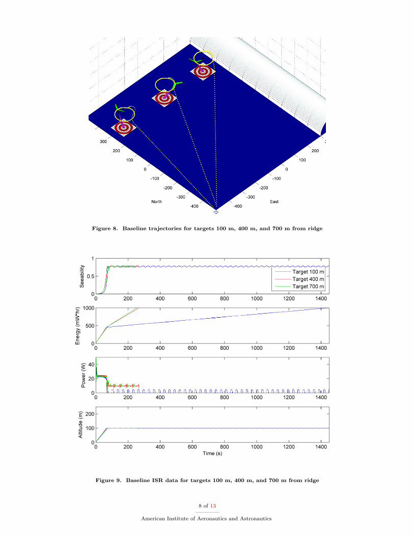
Figure 8. Baseline trajectories for targets 100 m, 400 m, and 700 m from ridge
Figure 9. Baseline ISR data for targets 100 m, 400 m, and 700 m from ridge
8 of 13
American Institute of Aeronautics and Astronautics
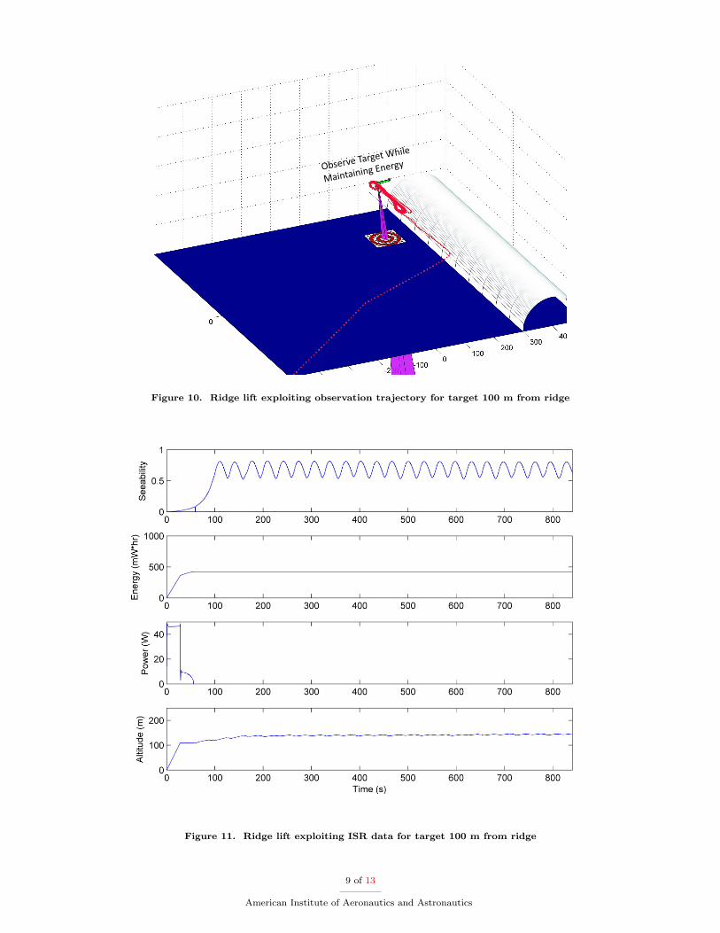
Figure 10. Ridge lift exploiting observation trajectory for target 100 m from ridge
Figure 11. Ridge lift exploiting ISR data for target 100 m from ridge
9 of 13
American Institute of Aeronautics and Astronautics
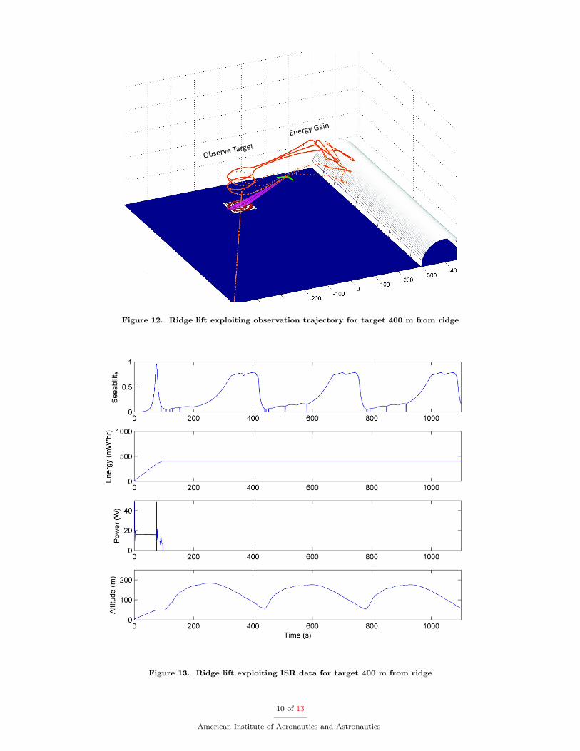
Figure 12. Ridge lift exploiting observation trajectory for target 400 m from ridge
Figure 13. Ridge lift exploiting ISR data for target 400 m from ridge
10 of 13
American Institute of Aeronautics and Astronautics
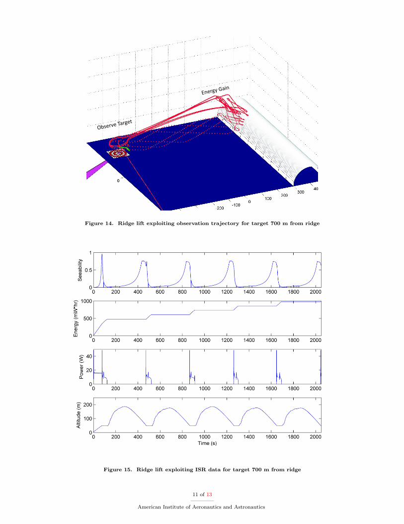
Figure 14. Ridge lift exploiting observation trajectory for target 700 m from ridge
Figure 15. Ridge lift exploiting ISR data for target 700 m from ridge
11 of 13
American Institute of Aeronautics and Astronautics

near a value of 0.1 as the UAV flies toward the ridge and then along the ridge gaining altitude (t ≈ 100 to220 s). Seeability increases to about 0.75 as the UAV glides unpowered to the target (t ≈ 220 to 320 s) andthen holds fairly constant while the UAV glides in a descending orbit over the target (t ≈ 320 to 420 s). Atthis point, the UAV glides unpowered back to the ridge at the 50 m lower altitude threshold (t ≈ 420 to440 s) where the seeability drops off as expected. Notice that once the UAV reaches the ridge initially, nopower is expended to sustain flight from this point forward. More energy (in the form of altitude gained) isharvested from the ridge than is expended flying from the target to the ridge and back. This excess energycan then be used to orbit over the target. Although there are gaps where the seeability falls below desiredlevels, the extended duration over which observations can occur is of significant value.
The third scenario considered has the target at 700 m from the ridge line or seven times the ridge radius.In this scenario, shown in Figure 14, the UAV flies directly to the target and then flies to the ridge to extractenergy as in the previous scenario. The UAV climbs unpowered with the help of ridge lift to the 175 maltitude ceiling and then glides toward the target. By the time it reaches the target and completes half anorbit, the UAV hits the low-altitude threshold of 50 m and powers its motor to fly back to the ridge.
Figure 15 shows the time histories for seeability, energy consumption, power, and altitude for the UAVwith the target located 700 m from the ridge. In this scenario, the energy harvested from the ridge is lessthan the energy expended in transit between the ridge and the target. The altitude lost in transit is morethan the altitude gained over the ridge. Because of this, battery energy must be used to power the flightfrom the target to the ridge. These intermittent pulses of power can be seen during the portions of the flightwhere the UAV is flying at 50 m altitude. These power pulses cause the energy consumption to step upuntil the 1000 mW-hr limit is reached at just over 2000 seconds. This energy consumed in transit leaves lessenergy to be consumed in observing the target. With the target positioned as far as it is from the ridge, abetter ISR strategy is to fly directly to the target and then use the battery energy to orbit over the target, asin Figures 8 and 9, which show seeability above 0.5 for approximately 190 continuous seconds. The seeabilitydata for the harvesting approach shown in Figure 15 shows that the seeability is intermittently above 0.5 forabout 350 seconds. While the harvesting approach nets a higher level of cumulative seeability, the intervalsof high seeability may not occur at times critical to the success of the mission.
V. Conclusions
This paper demonstrates the feasibility of utilizing energy harvesting strategies to enhance ISR missioneffectiveness. ISR targets near a ridge producing lift were considered. Simulation results showed that fortargets of interest at a distance from the ridge less than four times the ridge height, the target could beimaged in intervals that repeat indefinitely provided the wind conditions persist.
VI. Acknowledgments
This research was supported by the Office of Naval Research under STTR contract NOOOI4-09-M-0308to Mosaic ATM, Inc. and Brigham Young University.
References
1Morse, B., Engh, C., and Goodrich, M., “Aerial Video Coverage Quality Maps and Prioritized Indexing,” InternationalConference on Human-Robot Interaction, 2010, Accepted.
2Niefeldt, P., Beard, R., Morse, B., and Pledgie, S., “Integrated Sensor Guidance Using Probability of Target Identifica-tion,” Proceedings of the American Control Conference, 2010, Accepted.
3Wharington, J. M., “Heuristic Control of Dynamic Soaring,” 5th Asian Control Conference, 2004.4Allen, M. J., “Autonomous Soaring for Improved Endurance of a Small Uninhabited Air Vehicle,” AIAA Aerospace
Sciences Meeting and Exibit , 2005, AIAA-2005-1025.5Allen, M. J. and Lin, V., “Guidance and Control of an Autonomous Soaring Vehicle with Flight Test Results,” AIAA
Aerospace Sciences Meeting and Exhibit , 2007, AIAA 2007-867.6Edwards, D. J., “Implementation Details and Flight Test Results of an Autonomous Soaring Controller,” AIAA Guidance,
Navigation, and Control Conference, 2008, AIAA 2008-7244.7Langelaan, J. W., “Long Distance/Duration Trajectory Optimization for Small UAVs,” AIAA Guidance, Navigation and
Control Conference, August 2007, AIAA 2007-6737.8“U.S. Military Specification MIL-F-8785C,” November 1980.9Griffiths, S. R., “Vector Field Approach for Curved Path Following for Miniature Aerial Vehicles,” AIAA Guidance,
12 of 13
American Institute of Aeronautics and Astronautics

Navigation, and Control Conference and Exhibit , August 2006, AIAA 2006-6467.10Nelson, D. R., Barber, D. B., McLain, T. W., and Beard, R. W., “Vector Field Path Following for Miniature Air Vehicles,”
IEEE Transactions on Robotics, Vol. 37, No. 3, June 2007, pp. 519–529.
13 of 13
American Institute of Aeronautics and Astronautics